1
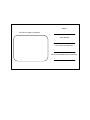
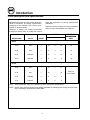
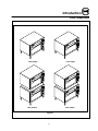
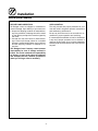
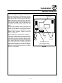
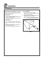
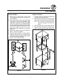
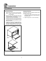
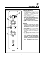
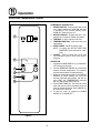
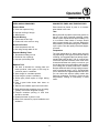
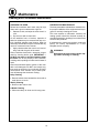
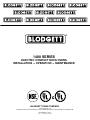
1400 SERIES
ELECTRIC COMPACT DECK OVENS
INSTALLATION - OPERATION - MAINTENANCE
BLODGETT OVEN COMPANY
www.blodgettcorp.com
50 Lakeside Avenue, Box 586, Burlington, Vermont 05402 USA Telephone: (802) 658Ć6600 Fax: (802)864Ć0183
PN 23326 Rev C (6/01)
E 2001 - G.S. Blodgett Corporation
IMPORTANT
WARNING: IMPROPER INSTALLATION, ADJUSTMENT,
ALTERATION, SERVICE OR MAINTENANCE CAN CAUSE
PROPERTY DAMAGE, INJURY OR DEATH. READ THE INĆ
STALLATION, OPERATING AND MAINTENANCE INĆ
STRUCTIONS THOROUGHLY BEFORE INSTALLING OR
SERVICING THIS EQUIPMENT
FOR YOUR SAFETY
Do not store or use gasoline or other flammable vapors or
liquids in the vicinity of this or any other appliance.
The information contained in this manual is important for the proper
installation, use, and maintenance of this oven. Adherence to these
procedures and instructions will result in satisfactory baking results
and long, trouble free service. Please read this manual carefully and
retain it for future reference.
Errors: Descriptive, typographic or pictorial errors are subject to correcĆ
tion. Specifications are subject to change without notice.
BLODGETT Ć THE REPUTATION YOU CAN COUNT ON
For a century and a half, The Blodgett Oven Company has
been building ovens and nothing but ovens. We've set the inĆ
dustry's quality standard for all kinds of ovens for every foodĆ
service operation regardless of size, application or budget. In
fact, no one in the foodservice industry has more oven engiĆ
neering experience than Blodgett, and no one offers more
models, sizes, and oven applications than Blodgett; gas and
electric, fullĆsize, halfĆsize, countertop and deck, convection,
Cook'n Hold, CombiĆOvens and the industry's highest quality
Pizza Oven line. For more information on the full line of
Blodgett ovens contact your Blodgett representative.
Model:
Your Service Agency's Address:
Serial Number:
Your oven was installed by:
Your oven's installation was checked by:
Table of Contents
Introduction
Oven Description and Specifications . . . . . . . . . . . . . . . . . . . . . . . . . . . . . . . .
Oven Components . . . . . . . . . . . . . . . . . . . . . . . . . . . . . . . . . . . . . . . . . . . . . . .
2
3
Installation
Delivery and Location . . . . . . . . . . . . . . . . . . . . . . . . . . . . . . . . . . . . . . . . . . . . .
Electrical Connection . . . . . . . . . . . . . . . . . . . . . . . . . . . . . . . . . . . . . . . . . . . . .
Oven Assembly . . . . . . . . . . . . . . . . . . . . . . . . . . . . . . . . . . . . . . . . . . . . . . . . . .
leg ATtachment . . . . . . . . . . . . . . . . . . . . . . . . . . . . . . . . . . . . . . . . . . . . . . .
Stand assembly . . . . . . . . . . . . . . . . . . . . . . . . . . . . . . . . . . . . . . . . . . . . . . .
Double Stacking . . . . . . . . . . . . . . . . . . . . . . . . . . . . . . . . . . . . . . . . . . . . . .
Deck Installation . . . . . . . . . . . . . . . . . . . . . . . . . . . . . . . . . . . . . . . . . . . . . .
Leveling the Oven . . . . . . . . . . . . . . . . . . . . . . . . . . . . . . . . . . . . . . . . . . . . .
4
5
6
6
7
7
8
8
Operation
Electro/Mechanical Thermostat and Timer . . . . . . . . . . . . . . . . . . . . . . . . . . .
Solid State Temperature Control . . . . . . . . . . . . . . . . . . . . . . . . . . . . . . . . . . .
General Baking Tips . . . . . . . . . . . . . . . . . . . . . . . . . . . . . . . . . . . . . . . . . . . . . .
9
10
11
Maintenance
Cleaning and Preventative Maintenance . . . . . . . . . . . . . . . . . . . . . . . . . . . . .
Troubleshooting Guide . . . . . . . . . . . . . . . . . . . . . . . . . . . . . . . . . . . . . . . . . . . .
12
13
Introduction
Oven Description and Specifications
Blodgett Deck ovens have set industry wide stanĆ
dards of excellence for baking characteristics,
performance and reliability. They remain unsurĆ
passed for product quality.
when the equipment is properly installed and
maintained.
Features include a full angle iron frame, all welded
radius corners and stainless steel exteriors.
Simplicity of design and quality construction
throughout assure years of trouble free service
VOLTS
PHASE
L1
L2
L3
ELECTRICAL
CONNECTION
AWG*
3.75
208
1
18
0
18
10
3.75
208
3
11
11
11
12
3.75
220Ć240
1
16
0
16
12
3.75
220Ć240
3
9
9
9
12
3.75
220
1
17
-
17
3.75
240
1
16
-
16
3.75
220/380
3
6
6
6
3.75
240/415
3
6
6
6
AMPERES
KW/SECTION
60 HZ
50 HZ
Size per
local codes
NOTE: Refer to page NO TAG in this manual for Electric Connection specifications.
NOTE: Double units can have phase loads partially equalized by matching lines during hookĆup. OtherĆ
wise, load ratings are double the above data.
2
Introduction
Oven Components
1405 Single
1415 single
1405 double
1415 double
Figure 1
3
Installation
Delivery and Location
DELIVERY AND INSPECTION
OVEN LOCATION
All Blodgett ovens are shipped in containers to
prevent damage. Upon delivery of your new oven:
The well planned and proper placement of your
oven will result in long term operator convenience
and satisfactory performance.
D
D
Inspect the shipping container for external damĆ
age. Any evidence of damage should be noted
on the delivery receipt which must be signed by
the driver.
Uncrate the oven and check for internal damĆ
age. Carriers will accept claims for concealed
damage if notified within fifteen days of delivery
and the shipping container is retained for inĆ
spection.
Be sure to place the oven in an area which is acĆ
cessible for proper operation and servicing.
It is essential that ventilation air not be obstructed
in any way if proper operation is to be assured. A
minimum of two inches (5 cm) must be maintained
between both the sides and the rear of the unit and
any wall.
The Blodgett Oven Company cannot assume
responsibility for loss or damage suffered in
transit. The carrier assumed full responsibility
for delivery in good order when the shipment
was accepted. We are, however, prepared to
assist you if filing a claim is necessary.
4
Installation
Electrical Connection
Ovens are supplied for operation on 208 volt or
220Ć240 volt installation. The thermostat, indicator
light and related switches are interconnected
through one power source supplied to the oven.
Wiring Label
Before making any connection to this oven, check
the rating plate attached to the bodyback to asĆ
sure that the voltage, phase and KW rating are
compatible with the electrical supply. See diaĆ
gram.
All ovens, when installed, must be connected and
electrically grounded in accordance with local
codes, or in the absence of local codes, with the
National Electrical Code, ANSI/NFPA 70-Latest
Edition and/or Canadian Electric Code CSA
C22.1 as applicable.
Wiring diagrams are located on the bodyback.
The supply conduit enters through the rear of the
oven and electrical connection is made to the terĆ
minal block secured to the panel at the back of the
control compartment. Electrical connection sizes
for a double 1400 oven are shown in Electrical
Connection AWG" column of the Electrical SpecifiĆ
cations found on page 2 of this manual. Wiring is
sized for 75_C copper wire at 125% of rated input.
Reference is from the National Electric Code ANSI/
NFPA 70Ć Latest Edition.
Rating
Plate
Wiring
Schematic
Installation Instructions
Do not install closer than
2 inches to any side or rear wall"
Figure 2
5
Installation
Oven Assembly
Before assembly and installation of the oven,
check that all components have been received. In
addition to the oven, legs, decks and/or other acĆ
cessories may be required.
LEG ATTACHMENT
1. Tip bottom oven section backward.
2. Attach each of the four legs into the nuts seĆ
cured in the oven bottom.
3. Tighten each leg and adjust the leg feet to
approximately the same height.
NOTE: Final leg fet adjustment will be reĆ
quired during the leveling operation.
Single Sections
D
D
4" (10 cm) legs are shipped inside the oven,
packed in a separate carton.
The decks are individually packaged and seĆ
cured to the oven back.
Double Sections
D
D
D
D
4" (10 cm) legs are packed in lower sections.
Spacer is shipped attached to the upper secĆ
tion.
Securing plate to attach units together is loĆ
cated in the upper section.
The decks are packaged with each section.
Figure 3
6
Installation
Oven Assembly
STAND ASSEMBLY
1. Attach legs to stand frame. Secure with
5/16Ć18 nuts and lockwashers (4 per leg). DO
NOT TIGHTEN.
2. Place shelf on legs. Holes in legs should align
with holes in shelf corner brackets. Legs
should be loose enough to assist in this alignĆ
ment. Place 1/4Ć20 x 2Ć1/4" bolts through legs
and into shelf brackets. Bolts should fit radius
of legs. Install 1/4Ć20 nuts after all four corners
are in place. Tighten four nuts. Do not over
tighten these nuts, deformity of leg surface
can occur.
3. Tighten the sixteen 5/16Ć18 nuts installed in
Step 1. DO NOT over tighten.
4. Optional Caster Assembly - Secure caster by
tightening with a wrench. Prior to placing oven
section on stand, check that locking casters
are on front of stand assembly.
5. Center oven on stand assembly.
DOUBLE STACKING
1. Connect the spacer assembly to the bottom of
th upper unit using 4 hex bolts.
2. Align and secure the spacer connecting plate
to the lower unit using 4 sheet metal screws.
NOTE: First remove the 4 sheet metal screws
along the top edge of the lower unit
panel.
3. Stack the upper unit on top of the lower unit.
4. Align and secure the spacer connecting to the
spacer assembly using 4 sheet metal screws.
Figure 5
Figure 4
7
Installation
Oven Assembly
LEVELING THE OVEN
DECK INSTALLATION
1. Remove the decks from the carton package.
NOTE: Handle cordierite shelves carefully to
avoid damage.
2. Open the oven door and remove the center
element assembly. The assembly is removed
by puling forward and unplugging.
3. Install one of the decks in the bottom position.
The deck should rest on the angles above the
element and should be positioned in contact
with the linerback.
4. Install the other deck in the center element asĆ
sembly on a flat surface. Reinstall the center
deck and element assembly in the oven. The
assembly is supported on four angle supports.
1400 Series ovens are equipped with NSF listed
adjustable sanitary legs.
1. Level the oven side to side and front to back
by placing a spirit level on the base frame of
the lower section.
2. Adjust the leg feet in or out as necessary.
Bottom
Deck
Top Deck
Center
Element
Figure 6
8
Operation
Electro/Mechanical Thermostat and Timer
COMPONENT DESCRIPTION
1. POWER SWITCH - Controls the power to the
oven. When switched to OVEN ON, the oven
is operating in the normal heating mode.
OVEN OFF, turns the oven off.
2. OVEN THERMOSTAT - Controls the oven
temperature at desired settings.
3. LIGHT OFF OVEN INDICATOR LIGHT When lighted indicates heaters are in operaĆ
tion. When the light goes out, the oven has
reached set operating temperature.
4. TIMER - Activates an electric buzzer which,
upon expiration of time, will sound to remind
the operator to remove the product.
1
2
OPERATION
LIGHT OFF
OVEN AT
TEMPERATURE
3
1. Depress the right hand side of the POWER
SWITCH (1) to turn the oven ON. The elements
will come on, this is indicated by the INDICAĆ
TOR LIGHT (3).
2. Set the THERMOSTAT (2) to the desired bakĆ
ing temperature.
3. The INDICATOR LIGHT (3) will go out when
the oven has reached the set operating temĆ
perature.
4. The TIMER (4) is set to measure a cooking
cycle by turning the knob clockwise to the deĆ
sired time. When selecting a cook time less
than ten minutes, turn the knob past the ten
minute interval and reverse direction to the deĆ
sired setting. At the end of the elapsed time
the buzzer will sound. The buzzer is turned off
by rotating the TIMER (4) to the OFF position.
NOTE: The TIMER will not control any temperĆ
ature functions.
OVEN
TEMPERATURE
C
F
4
TIMER
Figure 7
9
Operation
Solid State Temperature Control
COMPONENT DESCRIPTION
1. POWER SWITCH Ć Controls the power to the
oven. When switched to OVEN ON, the oven
is operating in the normal heating mode.
OVEN OFF, turns the oven off.
2. DIGITAL DISPLAY Ć Displays the time, temĆ
perature and controller related information.
3. TIME DIALĆ A dial to set the cook time.
4. TEMPERATURE DIALĆ A dial to set the cook
temperature.
5. START TIMER Ć Starts the timing cycle.
NOTE: To display the ACTUAL OVEN TEMĆ
PERATURE, press and hold for 3 secĆ
onds.
6. CANCEL Ć Press to cancel the end of time
cycle warning. Press to abort time cycle in
progress.
1
2
OPERATION
1. Toggle the POWER SWITCH (1) to OVEN ON.
The cooling fan will start.
2. Turn the TEMPERATURE DIAL (3) to select the
desired preĆheat temperature. The selected
preĆheat temperature will begin flashing.
3. When the temperature shown in the DIGITAL
DISPLAY (2) stops flashing, the oven has
reached operating temperature. Set the deĆ
sired TIME and TEMPERATURE manually
with the appropriate dials (3 and 4).
4. Press START TIMER (5). The timer will count
down the set time. Upon completion of the set
time, the buzzer will sound. Press CANCEL (6)
and remove the product.
5. To shut the oven off, toggle the POWER
SWITCH (1) to OVEN OFF.
3
4
5
6
Figure 8
10
Operation
General Baking Tips
PIZZA BAKING PROBLEMS
SUGGESTED TIMES AND TEMPERATURES
Uneven Bakes
Pizza should be placed in pans or on screens
when baked in the oven.
D
D
D
Oven door open too long
Improper scaling of dough
Warped pans
Time
Baking time will vary with the amount of garnish on
the top of the pizza. Generally speaking, pizzas
baked in pans should bake in approximately 7Ć1/2
to 12 minutes. Pizza baked on screens should
bake in approximately 5 to 7 minutes. Raising the
temperature to accelerate baking time is effective
up to a point. Then the quality of the bake begins
to lessen.
Product Burning
D
D
Thermostat set too high
Product left in the oven too long
Dried Out Product
D
D
Oven temperature too low
Not using enough water in mix
Temperature
Extended Baking Times
D
D
D
Temperature setting too low
Excessive door openings
Improper preĆheating time
BAKING TIPS
D
D
D
D
D
D
D
D
D
D
The deck is intended for cooking pizza and
bread products, other types of food may be
cooked in pans or containers.
Scale dough for consistent product.
Proof dough to proper consistency.
Sicilian type pizzas require a longer baking
time.
Pizza in pans bake slower than those on
screens.
Alternate use between upper and lower shelf.
Break bubbles that sometimes occur in baking.
(Usually occurs with refrigerator dough.)
Frequent needless opening of oven door
should be avoided.
Rotate placement of pizza in oven.
Refer to this manual for proper installation and
ventilation.
11
The ideal temperature for baking pizza pies will
vary depending on the type of pie and the method
of baking. It is suggested that you attempt experiĆ
mental initial bakes at 450_F 232_C), making note
of the time required to achieve a firm crust. If the
cheese breaks down too quickly or scorches, you
should then lower your temperature and lengthen
your baking time. If faster production is desired,
attempt additional bakes raising baking temperaĆ
tures in increments of 25_F (15_C). This will enable
you to determine the highest temperature at which
you can bake and achieve quality results with
maximum production. Pull time is critical at high
temperatures. Shifting is unnecessary in most
cases.
Maintenance
Cleaning and Preventative Maintenance
CLEANING THE OVEN
PREVENTATIVE MAINTENANCE
Painted and stainless steel ovens may be kept
clean and in good condition with a light oil.
The best preventative maintenance measures are,
the proper installation of the equipment and a proĆ
gram for routinely cleaning the ovens.
1. Saturate a cloth, and wipe the oven when it is
cold.
2. Dry the oven with a clean cloth.
On the stainless front or interiors, deposits of
baked on splatter may be removed with any nonĆ
toxic industrial stainless steel cleaner. Heat tint
and heavy discoloration may be removed with any
nonĆtoxic commercial oven cleaner.
1. Apply cleaners when the oven is cold, and alĆ
ways rub with the grain of the metal.
Clean Cordierite decks with a triangular scraper
used for cleaning broiler grids. IMPORTANT DO NOT use water or any other liquids to clean
the deck! Due to the porosity of the Cordierite,
cracking and/or spalling will often result if water is
used.
Clean the aluminized interior portion of the oven
with a mild detergent. DO NOT use caustic soluĆ
tions such as ammonia, lye or soda ash. DO NOT
use domestic oven cleaners. Any of these prodĆ
ucts will damage the aluminum coating.
Daily Cleaning
D
Remove residue from beneath the doors with a
small broom or brush.
Weekly Cleaning
D
Brush out the control area.
6 Month Cleaning
D
Clean secondary air ducts and air entry ports.
12
This oven requires no lubrication, however, the
venting system should be checked annually for
possible deterioration resulting from moisture and
corrosive flue products.
If maintenance or repairs are required, contact the
factory, the factory representative or a local
Blodgett service company.
WARNING!!
Disconnect the oven from the power supĆ
ply before servicing or cleaning.
Maintenance
Troubleshooting Guide
POSSIBLE CAUSE(S)
SUGGESTED REMEDY
SYMPTOM: Strong bottoms on the bakes
S Too much bottom heat
S Product left in the oven too long
S Reduce cook temperature and increase time
S Shorten cook time
SYMPTOM: Uneven bakes
S
S
S
S
S
S
S
S
Oven doors left open too long
Improper scaling of dough
Warped pans
Uneven product loading
Do not open door unnecessarily
Scale dough consistently
Change pans
Be sure to load the product evenly in pans
SYMPTOM: Product burning
S Thermostat set too high
S Product left in the oven too long
S Thermostat out of calibration
S Reduce cook temperature
S Shorten cook time
S *
SYMPTOM: Product dried out
S Oven temperature too low
S Not using enough water in the mix
S Thermostat out of calibration
S Increase cook temperature
S Increase water in product mix
S *
SYMPTOM: Extended baking times
S Temperature setting too low
S Excessive door openings
S Increase cook time
S Do not open door unnecessarily
*Denotes remedy is a difficult operation and should be performed by qualified personnel only. It is recommended, however, that
All repairs and/or adjustments be done by your local Blodgett service agency and not by the owner/operator. Blodgett cannot asĆ
sume responsibility for damage as a result of servicing done by unqualified personnel.
13
CUSTOMER
INSERT
WIRING DIAGRAM
HERE