1
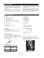
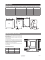
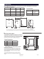
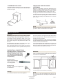
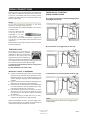
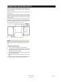
XXL DISHWASHER
INSTALLATION
INSTRUCTIONS
NT!
before
IMPORll TofAthese instructrio. ns
Read a he dishwashe
gt
installin
AUTOMATIC HIGH LOOP
The drain hose is fastened to the back of
the machine at the best height. To eliminate potential drain problems, leave this hose
in place.
CONTENTS
Introduction
What You Need
Dimensions
Preparing The Location
Dimensions
Custom Door Panel Dimensions
Water Supply
Drain Connections
Electrical Connections
Preparing The Dishwasher For Installation
Moving The Machine Into Place
Adjusting The Leveling Legs
Fastening The Dishwasher To The Cabinet
Installing The Toe Kick
Installation Checklist
Index
SAVE THESE INSTRUCTIONS FOR FUTURE REFERENCE
2
2
3
3
4
5
7
8
9
9
10
12
12
12
13
14
Introduction
Read these instructions carefully and completely before
you install the machine. The installation should be
carried out by a qualified person who is familiar with all
local codes and ordinances for electrical and plumbing
connections.
If a dishwasher is being installed in this area for the first
time, most of the cabinet work, plumbing, and electrical
has to be done before you move the machine into
place.
If you are replacing an old dishwasher, you must check
the plumbing connection and wiring before you move the
new dishwasher into place.
NOTE: Cosmetic damage must be reported to
the ASKO dealer within five days from the date of
purchase. As soon as you unpack the dishwasher,
thoroughly check it for cosmetic damage.
what you need
TOOLS
1)
Phillips No. 2 screwdriver
2)
Flat blade screwdriver
3)
Torx screwdriver size T 20
4)
Adjustable wrenches (if you use copper fittings)
5)
Open-ended wrench (1/2” [12 mm] or 5/8” [16 mm])
6)
Tape measure
7)
Spirit level
8)
Electric drill with 1- 5/8” drill bit
9)
Keyhole saw
MATERIALS
♦ Minimum 3/8" OD copper tubing of sufficient length
for your installation
♦ Shut-off valve and fittings for water supply line
Tip Guards (optional)
When it is not possible to attach the dishwasher to the
cabinet or the underside of the cabinet top, you should
install tip guards to prevent the machine from tipping
when you open the door.
Refer to page 7 for installation instructions.
The dishwasher is shipped with the high loop drain
hose, inlet hose and electrical cord attached and ready
to be connected. Please do not remove the high loop
connection for the drain line.
Tip Guards
(P/N 8070851)
Technical Data
Electricity
120V, 60Hz, 15 amp
Heating element:
1200 watt
Water pressure:
Max loading
4.2-140 psi,
0.03-1.0 MPa,
0.3-10 Bar
1300 watt
Customer Care Center
1-800-898-1879
www.askousa.com
Page DIMENSIONS
DD3232XLFI,D3251XLFI,D3531XLF
D5112XXL, D5122XXL,
D5152XXL, D5132XXL, D5223XXL, D5233XXL, D5253XXL, D5833XXL
U.S.
Metric
Height (Adjustable)
34-3/8”to 36-1/2”
874 to 927mm
Depth (Includes high loop)
24”
610mm
Width (Including fill strips)
24”
Depth W/Handle (HD)
Depth W/Door Open
Weight:
610mm
25-5/8”
651mm
49-3/4”
1266 mm
104 Ib
(HD models)
24"
610 mm
49-3/4"
1266 mm
25-5/8"
651 mm
5-1/4"-7-1/4"
135 - 185 mm
34-3/8" to 36-1/2"
874 to 927 mm
24"
610 mm
47 kg
Door
2"
50 mm
3-1/4"
85 mm
9"
230 mm
2-3/4"
70 mm
PreparING the location
The best place for your dishwasher is in the kitchen near
the sink. This makes it easier to connect the water and
drain supply lines.
A built-in dishwasher must be enclosed on the top, both
sides and the back.
Note: Maintain a 1/8” (3 mm) minimum clearance between
unit and cabinet.
Cutout Dimensions
Height
34-1/2” to 36-1/2”
876 to 927 mm
Width
24”
610 mm
2
60 3-5
0 /8"
m
m
Metric
23-5/8”
2"
50 mm
5-1/4" to 7-1/4"
135 to 185 mm
U.S.
Depth
34-1/2" to 36-1/2" minimum
876 to 927 mm
The electrical and water supplies should enter through the
area indicated by the shading on the illustration at right.
Preferably, they should come through the right side of the
machine. The access hole must be round and smooth and
no bigger than 2” (50 mm) in diameter.
4"
24"
610 mm
600 mm
Customer Care Center
1-800-898-1879
www.askousa.com
Page Dimensions
Unit Dimensions D5232XXLFI, D5233XXLFI, D5251XXFI, D5253XXLFI, D5531XXLFI,
D5731XXLFI, D5833XXLFI
U.S.
Metric
33-3/4” to
35-3/4”
857 to 908
mm
Width
23-5/8”
600 mm
Depth (Includes high
loop)
22-7/8”**
581 mm
49-3/4”
1266 mm
Height (Adjustable)
Depth W/Door Open
Weight:
108 Ib
Technical Data
Electricity
120V, 60Hz, 15 amp
Heating element:
1200 watt
Water pressure:
Max loading
49 kg
4.2-140 psi,
0.03-1.0 MPa,
0.3-10 Bar
1300 watt
49-3/4"
1266 mm
23-5/8"
600 mm
33-3 /4" to 35-3/4"
mm
5-1/4" - 7-1/4" 857 to 908
135 - 185 mm
22-7/8"
581 mm
Door
2"
50 mm
3-1/4"
85 mm
9"
230 mm
2-3/4"
70 mm
*If an accessory fill strip is used for FI models, 3/8” (9.5mm) must be added to the dishwasher height and cutout height
**Does not include the depth of a custom or optional door. If an ASKO optional door is used, add 2-1/2” (63.5 mm) to the depth
Custom Front Panels
33-3/4" to 35-3/4" minimum
857 to 908 mm
The D5232XXLFI, D5233XXLFI, D5251XXFI, D5253XXLFI,
D5531XXLFI, D5731XXLFI and D5833XXLFI can only be
installed with a fully-integrated custom door panel that extends
from the toe kick to the counter top. A one-piece custom door
panel with a curved handle is available (see page 6).
Cutout Dimensions
Height*
33-3/4” to 35 3/4”
857 to 908mm
Depth
23-5/8”
600 mm
Width
23-3/4” to 24”
2"
50 mm
603 to 610mm
5-1/4" to 7-1/4"
135 to 185 mm
NOTE: Maintain a 1/8” (3mm) minimum clearance
between unit and cabinet.
The electrical and water supplies should enter through
the area indicated by the shaded area. Preferably, they
should come through the right side of the machine. The
access hole must be round and smooth and no bigger
than 2” in diameter.
mm "
Metric
2
60 3-5
0 /8
U.S.
4"
23-3/4" to 24"
603 to 610 mm
*If an accessory fill strip is used for FI models, 3/8” (9.5
mm) must be added to the dishwasher height and cutout
height.
Customer Care Center
1-800-898-1879
www.askousa.com
Page custom door panel dimensions
Fitting the D5232XXLFI, D5233XXLFI, D5251XXFI, D5253XXLFI, D5531XXLFI,
D5731XXLFI, D5833XXLFI ASKO-Made or custom door panel - 4 inch toe kick.
The D5232XXLFI, D5233XXLFI, D5251XXFI, D5253XXLFI,
D5531XXLFI, D5731XXLFI and D5833XXLFI can be
installed with a fully integrated, buyer supplied custom
door panel or ASKO accessory panel that extends from the
toe kick to the counter top. The unit comes with everything
needed to make installing the door panel easy. The door
is predrilled for the panel’s mounting screws.
The custom panel should be a minimum of 3/4” (19mm)
thick.
Custom Panel Dimensions
Width
23-1/2” (597mm)*
Weight:
Up to 15 lbs.Up
to 20 lbs. with accessory spring.
Height
29-7/8” (760
mm)
Thickness:
Measured from the
top of the panel to
lower edge of the
kitchen cabinet.
3/4” (19mm)
Items provided with the unit
Two 3/8” screws (B) for temporarily hanging the
panel.
Six 1-3/4” screws (D) for mounting the custom
wooden panel to the dishwasher.
INSTALLING THE CUSTOM PANEL OR
ASKO ACCESSORY PANEL - 4 INCH TOE
KICK
A custom door panel should be installed before the unit
is mounted to the cabinet.
1. Fit the handle (A) onto the panel according
to the manufacturer’s instructions. (NOTE: A
handle should be used rather than a knob,
because a knob does not provide enough
grip.)
10266 7/8"
mm
15-7/16"
392 mm
D
29-7/8"
760 mm
Refer to the illustration at the right for
instruction references.
D
10266 7/8"
mm
D
IMPORTANT! The custom panel must not obstruct the
fan exhaust vent; otherwise, moisture from the vent
could eventually damage the cabinet and create drying
problems.
2. The two short screws (B) go into the back of the panel
15-7/16” (392 mm) from the upper edge of the panel and
10-7/8” (266 mm) from the center of the panel. Insert the
short screws into the panel, leaving 1/8” (3 mm) of space
between the screw head and the panel.
3. Hook the panel screws (B) into the keyholes (C) on the
dishwasher door.
4. Slide the panel to the left until it is centered in the
opening and secure the screws.
5. Open the door and use the six screws (D) supplied to
secure the panel to the door.
NOTE:
If the door panel weighs more than 15 pounds, you
may need to order the heavy-duty door springs.
*
ADJUSTING THE DOOR SPRINGS
Before you push the dishwasher into the cabinet opening,
test the door to make sure it stays in place at any angle. If
it tends to fall down, pull out the machine and adjust the
tension of the door springs on the sides of the machine
by moving them one hole farther back or by twisting the
spring to make it shorter.
*Max panel width cannot exceed cutout dimensions less
1/8” (2.5mm) reveal on each side.
Customer Care Center
1-800-898-1879
www.askousa.com
Shorten
Page D5233xXLFI, D5253xXLFI, D5833xXLFI DOOR PANEL INSTALLATION
OPTIONS
4-iNCH TOE KICK INSTALLATIONS
Panel extends from toe kick to cabinet top.
Custom panels that extend to the cabinet top
30-1/8"
765 mm
The preferred installation option for a 4” toe kick is to
extend the custom panel to the cabinet top (as illustrated).
A one-piece ASKO accessory panel with a curved handle
is available for 4-inch toe kick installations.
23-1/2"*
597 mm
4-inch toe kick
XLFI TRIM KIT INSTALLATION OPTIONS
ASKO XLFI dishwashers can be installed either with or without accessory fill strips depending on the type of installation.
If the dishwasher cutout has been cut to European widths of 23-5/8”, the unit won’t require fill strips. If the dishwasher
cutout is a standard 24” wide, we have fill strips that make the unit 24” wide.
Asko accessory panel
installation
Custom wood panel installation
The ASKO accessory fill kit 8077317-95 which includes
the counter saver fill strip and both side fill strips should
be installed in the back mounting holes on the fill kit.
The ASKO accessory fill kit 8078982-95 which includes
the counter saver fill strip and both side fill strips should
be installed in the front mounting holes on the fill kit.
Make the custom wood panel the width of the dishwasher
cutout minus 1/8” reveal on each side.
*Max panel width cannot exceed cutout dimensions less
1/8” (2.5mm) reveal on each side.
Customer Care Center
1-800-898-1879
www.askousa.com
Page CORNER INSTALLATION
If the dishwasher is installed in a corner, there must be a
minimum clearance of 2” (50 mm) from the side wall so
the door can open.
Installing the Tip Guards
(optional)
When it is not possible to fasten the dishwasher to the
cabinet, you should install a tip guard to prevent the
machine from tipping when the door is opened. The tip
guards can be attached either to the floor or the wall.
The tip guard should be mounted behind the machine,
18-1/2” (470 mm) from the front of the machine centered in
the width of the cutout opening. (Note: This measurement
could vary, depending on the thickness of the custom
panel, if any.)
Rear
2” clearance
Tip Guards
(P/N 8070851)
NOTE:
We recommend that you install tip guards when it isn’t
possible to fasten the dishwasher to the cabinet.
WATER SUPPLY
WARNING!!
Plumbing connections must comply with applicable
sanitary, safety and plumbing codes in your area.
The machine can be connected to either a hot or cold
water supply. If a cold water supply is used, the washing
times will be longer but the performance will not be
affected.
The dishwasher comes with a 6-foot PEX water supply
line that has a 3/8” NPT female connection.
After determining where the water supply line will enter
under the sink, drill a 1 5/8” to 2” (41mm to 50mm) access
EASYINSTALL CONNECTIONS
PEX tubing with 3/8” compression fitting
PEX tubing has a 95-year spec life. Fits
American dishwasher water supply
valves. Be sure to install the O-Ring
which is attached to the PEX tubing
in a plastic bag
hole and run the line to the approximate inlet valve location
shown in the figure below. The water line inlet valve is on
the right rear of the machine.
For service convenience, a shut-off valve (not supplied)
should be installed in the supply line in an easily accessible
location, such as, beneath the sink.
It is important that the water supply line and the shut-off
valve have a sufficient flow volume. At last 3 gallons (12
liters) per minute must be able to pass through the line.
The water pressure should be 4.2-140 psi.
WARNING!
In order to prevent heat damage to the inlet valve, all
solder connections must be made before the water line
is connected to the dishwasher.
Drain hose boot
Ready to be cut to desired
drain connection. Only
one clamp required.
Electrical cord
120 volts, 15 amp cord is supplied with
the dishwasher.
1. Water supply
2. Water supply valve to dishwasher (not supplied)
Warning!
Do not use an extension cord for this appliance.
NOTE:
Be sure to run the PEX tubing through the hole to
sink compartment before moving the dishwasher into
position.
Customer Care Center
1-800-898-1879
www.askousa.com
Page DRAIN CONNECTIONS
ASKO provides a 7/8” (22 mm) diameter corrugated drain
hose which is connected to the back of the unit to form
a high loop. If additional drain hose is needed, please
purchase an ASKO drain hose extension kit with a 7/8”
(22mm) copper tube.
THREE WAYS TO INSTALL
DRAIN CONNECTIONS
A)Typical connection to sink plumbing before
trap (high loop drain)
NOTE:
Do not use any fittings anywhere in the drain
line that are less than 7/8” (22 mm) ID.
The access hole for the drain line should be 1-5/8” (41 mm)2” (50mm) max.
The end of the drain line
is 1/2” (12 mm), but it is
adjustable to 7/8”, 3/4”,
5/8” (22mm, 19 mm,
and 16 mm). If the drain connection is larger than
1/2” (12 mm), you can easily cut the drain line to fit the
connection.
The illustrations to the right show three ways to connect
the drain supply line.
508
B)Connection to air gap then to the trap
THE HIGH LOOP
The high loop is necessary for
proper draining. Therefore, all ASKO
dishwashers have the drain hoses
attached to the drain pump and
fastened to the top back of the unit, as
illustrated. This gives the drain hose an automatic high
loop, which is necessary for proper draining. The drain
hose is fastened at the best high loop height.
508
To eliminate potential drain problems, simply leave
this hose in place.
DO NOT REMOVE THE HIGH LOOP!
IMPORTANT THINGS TO REMEMBER:
♦ Failure to provide the proper drain connection height
(minimum of 20" (508 mm) above the bottom of the
dishwasher base) or a 20” (508 mm) high loop will
result in improper drainage, which will damage the
machine.
♦ No part of the drain hose should be higher than 35"
(889 mm) from the bottom of the dishwasher.
♦ The drain hose can be extended to a maximum length
of 10 feet (3048 mm). Joints and jointed tubes, if any,
must have a minimum 5/8" (16 mm) ID.
♦ If the drain line is going to be connected to a waste
disposer, be sure to remove the knockout or plug
from the fitting on the disposer before connecting
the drain line.
♦ Do not use fittings smaller than 5/8” (16 mm);
otherwise the water may not drain properly.
When the installation is ready, open the supply valve
and let the pressure act for a while. Then check that all
connections are tight and there are no leaks.
C)Connection to waste disposer with air gap
508
NOTE:
Don’t forget to remove the knockout or plug from the
disposer fitting.
Customer Care Center
1-800-898-1879
www.askousa.com
Page ELECTRICAL connections
WARNING!
Before working on wiring for any electrical appliance,
be sure the electrical power has been turned off at the
breaker/fuse box.
Warning!
Do not use an extension cord for this appliance.
WARNING!
Disconnect electrical power supply and place a tag at
the disconnect switch indicating that you are working on
the circuit.
WARNING!
Electrical and grounding connections must comply with
the applicable portions of the national electrical code
and/or other local electrical codes.
The dishwasher comes with an electrical
cord for 120 volts, 15 amp supplied. This
cord should be plugged into the 120 volt
outlet under the sink.
If the cord is not long enough, or if a hard-wire installation
is needed, follow instructions on page 10.
7
185
NOTE:
Access holes should be 1-5/8” to 2” (41 mm to 50 mm)
in diameter with no sharp edges.
Grounding instructions
This unit must be grounded to operate properly. It must be
connected to a grounded metal, permanent wiring system,
or an equipment-grounding conductor must be run with
the circuit conductors and connected to the equipmentgrounding terminal or lead of the appliance.
Damage to the dishwasher could occur if it is not properly
grounded.
WARNING!
Make sure the water supply line, drain line and branch
circuit wiring do not touch any exposed terminals of
dishwasher wiring.
PREPARING THE DISHWASHER FOR INSTALLATION
At this point the styrofoam, plastic wrap, and the wood
pallet (base) should be removed from the dishwasher.
Now is an excellent time to inspect for any shipping
damage. Should you find any damage, you should report
it to your dealer or builder immediately.
Be sure to remove the toe kick and toe kick insulation (only
on certain models) from the top of the dishwasher.
SLIDES FOR LEGS
The unit comes with white plastic slides for the legs to
protect the kitchen floor from being
damaged when you slide the unit into
place. The slides simply snap onto the
bottom of the legs.
Protective slides for legs simply
snap onto the bottom of the legs.
Trim Strip Installation
Install the optional Fill kit seen on page 6 if desired (FI
models only). Use the screws that come with the fill kit to
attach the side and top trim pieces to the unit.
Adjusting the door springs
Before you install the unit into the cabinet, open the door
to make sure it stays open at
any angle. If it tends to fall
down or snap shut, pull out the
machine and tension the door
springs on the sides of the
machine by moving them one
hole farther back or by twisting
the spring to make it shorter.
Shorten
The accessory door panel or
custom wood panel must be
installed on FI dishwashers to properly adjust tension on
the door springs. If that doesn’t resolve the problem, you
may need to purchase the heavy-duty door springs (part
number 8076163-77).
NOTE:
If the door panel weighs more than 15 pounds, you may
need to order the heavy-duty door springs. (See page
5.)
Customer Care Center
1-800-898-1879
www.askousa.com
Page Moving the machine into place
WARNING!
Make sure you put the protective slides on the legs to
prevent damaging the floor when you slide the unit into
place (see page 9).
1. Position the machine in front of the cabinet opening.
2. Make the height adjustment while the dishwasher is
in front of the opening.
3. Pull out the drain hose to ensure there are no sharp
bends.
4. Start to feed water and drain lines and electric cord (if
necessary) into the access hole in the cabinet.
5. Gently slide the unit into the dishwasher opening. As
you do this, feed the drain line and inlet hose into the
access hole in the side of the cabinet.
As you slide the unit into place, feed the drain line and
inlet hose into the access hole in the side of the cabinet.
Warning!
Be careful of sharp edges.
CONNECTING THE ELECTRIC CABLE
If the cord is not long enough, or if a hard-wire installation
is needed, follow the steps below to complete the
electrical connection.
4. Connect ground wire to ground connection screw on
the bottom.
WARNING!
Before starting this procedure, be sure the power is turned
off at the breaker/fuse box.
1. Connect supply cable with
a UL-listed strain relief
bushing (if nonmetallic
cable is to be used).
2. Connect branch circuit white
lead to N lead on filter.
3. Connect branch circuit black
lead to L lead on filter.
NOTE:
When doing a hard-wire installation, you must remove the
supplied power cord.
Customer Care Center
1-800-898-1879
www.askousa.com
Page 10
CONNECTING THE WATER SUPPLY
In order to prevent heat damage to the inlet valve, all
solder connections must be made before the water supply
line is connected.
Flush the water supply line prior to connecting it to the
water fill tube.
The unit has a float switch in the base pan to protect
against flooding. If the inlet valve connection is not seated
properly, water may leak into the base pan and activate
the float switch.
It is important that the water supply line and the shut-off
valve have a sufficient flow volume. At last 3 gallons (12
liters) per minute must be able to pass through the line.
The water pressure should be 4.2-140 psi.
(1)
(2)
Water supply
Water supply valve (not supplied)
NOTE:
Be sure to run the PEX tubing through the hole to sink
compartment before moving the dishwasher into position.
TESTING for leaks
1. Turn on the water supply and check for leaks.
2. Turn the power on at breaker/fuse box and test the
dishwasher operation by running a Rinse cycle. (This
should take about four minutes.)
3. Turn off the electrical power and check for leaks under
the dishwasher and sink.
4. Make sure that no kinks have developed in the drain
lines.
If there are no leaks and the dishwasher seems to be
working properly, continue with the installation.
Customer Care Center
1-800-898-1879
www.askousa.com
Page 11
Adjusting the LEVELING LEGS
Now that all the connections are made and the machine
is in place under the cabinet, you should make the final
height adjustment.
1. You should set the rear
foot first. To do this, use a
screwdriver to rotate the
adjusting screw on the
bottom front of the machine.
Turn the screw clockwise to
raise the foot and counter clockwise to lower it.
2. Using a 5/8” (16 mm) wrench, adjust the locking nuts
until the machine is level. (The machine may have an
inclination of 3/16” (5mm) maximum without affecting
its performance.)
3. When the feet are properly adjusted, tighten the
locking nuts to the base pan.
FastenING the dishwasher to the cabinet
NOTE:
If you want to mount a wooden door or a custom panel.
Do this before fastening the dishwasher to the cabinet!
See chapter “Fitting custom door panel”
It’s necessary to fasten the dishwasher to the cabinet so
it won’t tilt when the door is opened or if something heavy
is placed on the door. Use only the stainless steel screws
provided with the machine.
1. Use option A for U.S. or European
standard installations. Use option
B only for European standard
installations, or U.S. installations
where there is a hard counter-top
such as tile or marble.
NOTE
When it is not possible to attach the dishwasher to the
cabinet, you should install tip guards. (See “Tip Guards”
on page 2.):
2. Cover the screw heads with the plastic plugs provided
with the machine.
3. When the machine is properly attached, check
that the feet are tight against the floor and that the
machine is level.
NOTE:
Be sure to use white spacers to keep from over-tightening
the mounting screws.
INSTALLING THE TOE KICK
SETTING THE TOE KICK DEPTH
1. Press the grey catches towards each other to release
the toe kick brackets.
2. Pull out the toe kick brackets as far as the installation
requires to provide the proper toe kick depth.
3. Once the toe kick brackets are at the appropriate depth,
press the grey catches away from each other to lock
the toe kick brackets in place.
4. The back side of the toe kick has hooks that will hang
the toe kick on the toe kick brackets. Lift the toe kick
up and let the hooks slide onto the brackets as you
lower the toe kick to the floor.
Customer Care Center
1-800-898-1879
www.askousa.com
Page 12
INSTALLATION CHECKLIST
Asko - Dishwasher
Appliance Installation Checklist
• Remove packaging and check for cosmetic damages.
• Remove the information packets from inside the dishwasher.
• Attach any accessories as required by the installation. Fill strips,
wooden door panels, accessory door panels...
• Attach the drain line using the largest section of the disposer boot
allowable. Leave the high loop in place.
• Attach the PEX fill hose. Don’t forget to use the O-ring.
• Plug the dishwasher into the wall.
• Turn on the water and check the fill line connections for leaks.
• Slide the unit into the cabinet and level the machine front to rear,
and left to right.
• Mount the unit to the cabinet.
• Turn the power to the unit on and start a cycle. Make sure there are
no drain leaks.
• Show the customer their warranty card, and help them locate the
model and serial number on the unit.
• Leave all user books for consumer.
Customer Care Center
1-800-898-1879
www.askousa.com
Page 13
index
C
Cabinet, fastening unit to 12
Connecting to water supply 11
Cosmetic damage 2
D
Door springs, adjusting 9
Drain connections 8
E
Electrical cable connection 10
Electrical connections 9
F
Fastening unit to cabinet 12
G
Grounding instructions 9
H
High loop 8
Hot water supply 7
L
Leaks, testing for 11
Leveling legs, adjusting 12
M
Materials 2
S
Slides for rear legs 9
T
Technical data 2
Tip guards 2
installing 7
Toe kick, installing 12
Tools 2
V
Water connection 11
Water flow volume 7
Customer Care Center
1-800-898-1879
www.askousa.com
Page 14
Notes
Customer Care Center
1-800-898-1879
www.askousa.com
Page 15
Customer Care Center
1-800-898-1879
www.askousa.com
Art. No 80 820 16 Rev. 01
Page 16


![i36l I33l EIrIIIllIrrllIl tlrxlrllIr I lrlllr]lll It DA2](http://vs1.manualzilla.com/store/data/006759536_1-e1b2d27f25e11b765edbcc7af9879218-150x150.png)