1
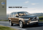
XC90
Owner's Manual
L:7:9>I>DC
I
nf
or
mat
i
onPr
ovi
dedby:
I
nf
or
mat
i
onPr
ovi
dedby:
Welcome to the world-wide family of Volvo owners. We trust that you
will enjoy many years of safe driving in your Volvo, an automobile
designed with your safety and comfort in mind. We encourage you
to familiarize yourself with the equipment descriptions and operating
instructions in this manual.
We also urge you and your passengers to wear seat belts at all times
in this (or any other) vehicle. And, of course, please do not operate a
vehicle if you may be affected by alcohol, medication or any impairment that could hinder your ability to drive.
Your Volvo is designed to meet all applicable federal safety and
emission standards. If you have any questions regarding your vehicle,
please contact your Volvo retailer or see the section "Contacting
Volvo" in this manual's "Introduction" chapter for information on getting in touch with Volvo in the United States and Canada.
I
nf
or
mat
i
onPr
ovi
dedby:
Contents
00 01 02
00 Introduction
01 Safety
Important information................................. 8
Environment.............................................. 13
Important warnings................................... 14
Occupant safety........................................
Seat belts..................................................
Supplemental Restraint System...............
Front airbags.............................................
Occupant Weight Sensor..........................
Side impact protection airbags.................
Inflatable Curtain.......................................
Whiplash Protection System.....................
Child safety...............................................
Child restraint systems.............................
Infant seats...............................................
Convertible seats......................................
Booster cushions......................................
ISOFIX/LATCH lower anchors..................
Top tether anchors....................................
Integrated booster cushion.......................
02 Instruments and controls
18
20
23
24
28
31
33
35
37
40
42
44
47
48
50
51
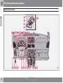
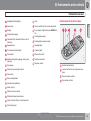
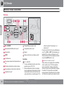
Instrument overview..................................
Instrument panel.......................................
Information display...................................
Center console buttons............................
Steering wheel adjustment.......................
Lighting panel...........................................
Manually unlocking the fuel filler door......
Left-side steering wheel lever...................
Right-side steering wheel lever.................
Hazard warning flashers...........................
Trip computer...........................................
Cruise control............................................
12-volt sockets.........................................
Hood/tailgate............................................
Power windows.........................................
Mirrors.......................................................
Power moonroof.......................................
56
58
62
64
66
67
70
71
72
75
76
78
80
81
82
84
87
HomeLink® Wireless Control System*...... 89
I
nf
or
mat
i
onPr
ovi
dedby:
2
* Option/accessory, for more information, see Introduction.
Contents
03 04 05
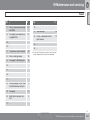
03 Climate
04 Interior
Climate control system – general information............................................................ 94
Air distribution........................................... 96
Electronic climate control (ECC)............... 98
Front seats..............................................
Rear seats...............................................
Interior lighting........................................
Storage compartments...........................
Securing cargo........................................
05 Locks and alarm
104
108
111
114
119
Remote keys and key blades..................
Locking and unlocking............................
Child safety locks....................................
Alarm.......................................................
126
130
132
133
I
nf
or
mat
i
onPr
ovi
dedby:
3
Contents
06 07 08
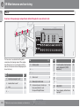
06 Starting and driving
General information................................
Fuel requirements...................................
Refueling.................................................
Starting the vehicle.................................
Ignition switch and steering wheel lock. .
Economical driving..................................
Difficult driving conditions......................
Automatic transmission..........................
Jump starting..........................................
All Wheel Drive*.......................................
Brake system..........................................
Parking brake..........................................
Stability system.......................................
Front/rear park assist*.............................
Towing....................................................
Towing a trailer.......................................
Detachable trailer hitch...........................
Load carriers (accessory)........................
Cold weather precautions.......................
Before a long distance trip......................
Blind Spot Information System*..............
07 Wheels and tires
138
139
141
143
145
146
147
148
151
152
153
156
157
159
161
163
166
167
168
169
170
General information................................
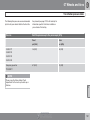
Tire inflation ............................................
Tire inflation pressure table.....................
Tire designations.....................................
Glossary of tire terminology....................
Vehicle loading........................................
Uniform Tire Quality Grading..................
Snow chains, snow tires, studded tires. .
Temporary spare.....................................
Tire Sealing System ...............................
Changing wheels....................................
Tire Pressure Monitoring System (TPMS)
I
nf
or
mat
i
onPr
ovi
dedby:
4
* Option/accessory, for more information, see Introduction.
08 Car care
176
179
181
182
184
185
186
187
188
189
195
200
Washing and cleaning the vehicle.......... 206
Paint touch up......................................... 210
Contents
09 10 11
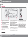
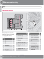
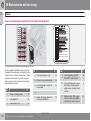
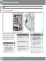
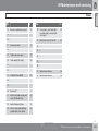
09 Maintenance and servicing
Volvo service...........................................
Maintaining your vehicle.........................
Working on your vehicle.........................
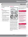
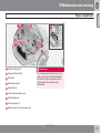
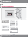
Engine compartment...............................
Engine oil................................................
Fluids......................................................
Wiper blades...........................................
Battery.....................................................
Replacing bulbs......................................
Fuses......................................................
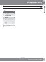
10 Audio
214
215
217
219
220
222
224
225
228
236
11 Specifications
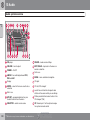
Audio system overview...........................
Audio system controls............................
Radio functions.......................................
SiriusXM satellite radio........................
Auxiliary equipment................................
CD player/changer..................................
Menu structure........................................
250
251
256
261
265
268
271
Bluetooth® hands-free connection......... 272
Rear Seat Entertainment – Dual Screen
(RSE)*...................................................... 278
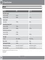
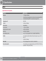
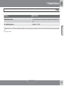
Label information.................................... 284
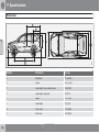
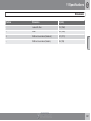
Dimensions ............................................ 286
Weights .................................................. 288
Fluids...................................................... 290
Suspension............................................. 292
Engine oil................................................ 293
Engine specifications.............................. 294
Electrical system..................................... 295
Three-way catalytic converter................. 296
Overview of information and warning symbols ........................................................ 297
Volvo programs....................................... 299
I
nf
or
mat
i
onPr
ovi
dedby:
* Option/accessory, for more information, see Introduction.
5
Contents
12
12 Index
Index....................................................... 300
I
nf
or
mat
i
onPr
ovi
dedby:
6
Contents
I
nf
or
mat
i
onPr
ovi
dedby:
7
Introduction
Important information
Contacting Volvo
About this manual
In the USA:
• Before you operate your vehicle for the first
Volvo Cars of North America, LLC
Customer Care Center
1 Volvo Drive,
P.O. Box 914
Rockleigh, New Jersey 07647
1-800-458-1552
www.volvocars.us
In Canada:
Volvo Cars of Canada Corp
National Customer Service
time, please familiarize yourself with the
information found in the chapters "Instruments and controls" and "Starting and
driving."
• Information contained in the balance of the
used for reference. For this reason, it
should be kept in the vehicle for ready
access.
Footnotes
www.volvocars.ca
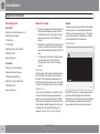
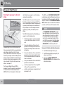
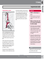
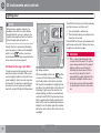
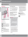
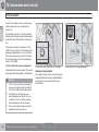
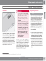
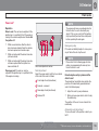
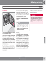
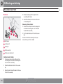
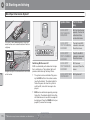
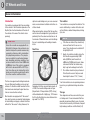
Display texts
G031590
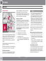
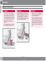
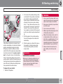
There are several displays in the driver’s field
of vision that show messages generated by
various systems and functions in the vehicle.
These texts are indicated in the Owner’s Manual by being in slightly larger type than the surrounding text and are printed in gray, (for
example: Change doors unlock setting).
I
nf
or
mat
i
onPr
ovi
dedby:
8
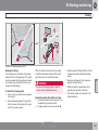
Risk of injury
• The manual is structured so that it can be
1-800-663-8255
North York, Ontario M2H 2N7
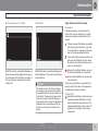
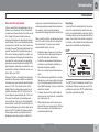
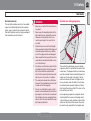
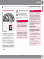
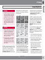
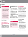
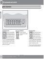
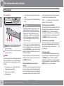
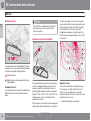
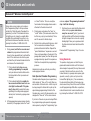
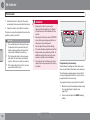
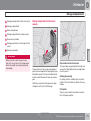
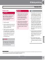
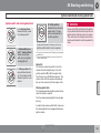
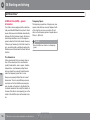
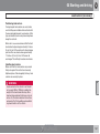
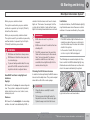
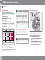
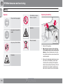
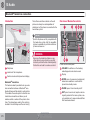
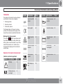
There are various types of decals in the vehicle
whose purpose is to provide important information in a clear and concise way. The importance of these decals is explained as follows,
in descending order of importance.
manual is extremely useful and should be
read after operating the vehicle for the first
time.
Certain pages of this manual contain information in the form of footnotes at the bottom of
the page. This information supplements the
text that the footnote number refers to (a letter
is used if the footnote refers to text in a table).
175 Gordon Baker Road
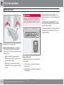
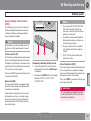
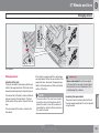
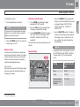
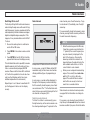
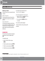
Decals
Black ISO symbols on a yellow warning background, white text/image on a black background. Decals of this type are used to indicate
potential danger. Ignoring a warning of this
type could result in serious injury or death.
Introduction
Important information
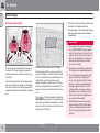
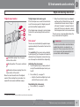
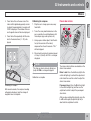
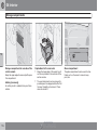
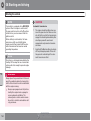
Risk of damage to the vehicle
Information
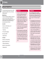
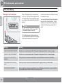
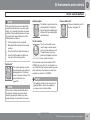
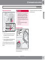
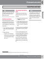
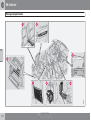
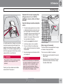
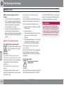
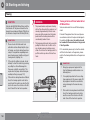
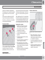
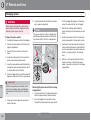
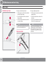
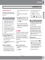
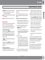
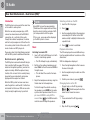
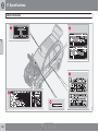
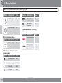
Types of lists used in the manual
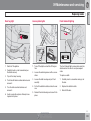
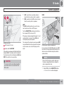
Procedures
Procedures (step-by-step instructions), or
actions that must be carried out in a certain
order, are arranged in numbered lists in this
manual.
White ISO symbols and white text/image on a
black or blue warning background and space
for a message. If the information on decals of
this type is ignored, damage to the vehicle
could result.
G031593
G031592
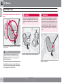
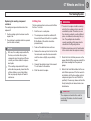
If there is a series of illustrations associated
with step-by-step instructions, each step
in the procedure is numbered in the same
way as the corresponding illustration.
White ISO symbols and white text/image on a
black background. These decals provide general information.
NOTE
The decals shown in the Owner’s Manual
are examples only and are not intended to
be reproductions of the decals actually used
in the vehicle. The purpose is to give an indication of how they look and their approximate location in the vehicle. The applicable
information for your particular vehicle can
be found on the respective decals in the
vehicle.
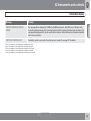
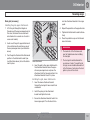
Lists in which letters are used can be found
with series of illustrations in cases where
the order in which the instructions are carried out is not important.
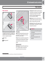
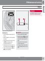
Arrows with or without numbers are used
to indicate the direction of a movement.
Arrows containing letters are used to indicate movement.
If there are no illustrations associated with a
step-by-step list, the steps in the procedure
are indicated by ordinary numbers.
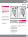
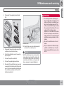
Position lists
Red circles containing a number are used
in general overview illustrations in which
certain components are pointed out. The
corresponding number is also used in the
position list's description of the various
components.
I
nf
or
mat
i
onPr
ovi
dedby:
9
Introduction
Important information
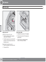
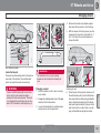
Bullet lists
Bullets are used to differentiate a number of
components/functions/points of information
that can be listed in random order.
NOTE
•
For example:
• Coolant
• Engine oil
Continued
` `This symbol can be found at the lower right
corner of an odd-numbered (right-hand) page
to indicate that the current topic is continued
on the following page.
Options and accessories
Optional or accessory equipment described in
this manual is indicated by an asterisk.
Optional or accessory equipment may not be
available in all countries or markets. Please
note that some vehicles may be equipped differently, depending on special legal requirements.
Contact your Volvo retailer for additional information.
WARNING
All information, illustrations and specifications contained in this manual are
based on the latest product information
available at the time of publication.
•
Volvo reserves the right to make model
changes at any time, or to change specifications or design without notice and
without incurring obligation.
•
Do not export your Volvo to another
country before investigating that country's applicable safety and emission
control requirements. In some cases it
may be difficult or impossible to comply
with these requirements. Modifications
to the emission control system(s) may
render your Volvo not certifiable for
legal operation in the U.S., Canada and
other countries.
WARNING
If your vehicle is involved in an accident,
unseen damage may affect its drivability
and safety.
I
nf
or
mat
i
onPr
ovi
dedby:
10
CALIFORNIA proposition 65
Engine exhaust, some of its constituents,
and certain vehicle components contain or
emit chemicals known to the state of California to cause cancer, and birth defects or
other reproductive harm. In addition, certain
fluids contained in vehicles and certain
products of component wear contain or
emit chemicals known to the State of California to cause cancer, and birth defects or
other reproductive harm.
WARNING
Certain components of this vehicle such as
air bag modules, seat belt pretensioners,
adaptive steering columns, and button cell
batteries may contain Perchlorate material.
Special handling may apply for service or
vehicle end of life disposal.
See www.dtsc.ca.gov/hazardouswaste/
perchlorate.
Introduction
Important information
Shiftlock
Points to keep in mind
Volvo Structural Parts Statement
When your vehicle is parked, the gear selector
is locked in the P (Park) position. To release the
selector from this position, turn the ignition key
to position II (or start the engine), depress the
brake pedal, press the button on the front side
of the gear selector and move the selector from
P (Park).
• Do not export your Volvo to another coun-
Volvo has always been and continues to be a
leader in automotive safety. Volvo engineers
and manufactures vehicles designed to help
protect vehicle occupants in the event of a collision.
Keylock
When you switch off the ignition, the gear
selector must be in the P (Park) position before
the key can be removed from the ignition
switch.
Anti-lock Brake System (ABS)
The ABS system in your vehicle performs a
self-diagnostic test when the vehicle first reaches the speed of approximately 12 mph
(20 km/h). The brake pedal will pulsate several
times and a sound may be audible from the
ABS control module. This is normal.
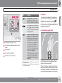
Fuel filler door
try before investigating that country's
applicable safety and exhaust emission
requirements. In some cases it may be difficult or impossible to comply with these
requirements. Modifications to the emission control system(s) may render your
Volvo not certifiable for legal operation in
the U.S., Canada and other countries.
• All information, illustrations and specifications contained in this manual are based on
the latest product information available at
the time of publication. Please note that
some vehicles may be equipped differently, depending on special legal requirements. Optional equipment described in
this manual may not be available in all markets.
• Volvo reserves the right to make model
changes at any time, or to change specifications or design without notice and without incurring obligation.
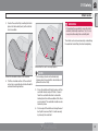
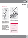
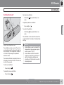
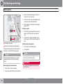
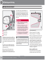
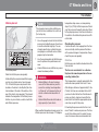
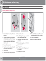
Press the button on the light switch panel (see
the illustration on page 67) when the vehicle
is at a standstill to unlock the fuel filler door.
Please note that the fuel filler door will remain
unlocked until the vehicle begins to move forward. An audible click will be heard when the
fuel filler door relocks.
Volvos are designed to absorb the impact of a
collision. This energy absorption system
including, but not limited to, structural components such as bumper reinforcement bars,
bumper energy absorbers, frames, rails, fender
aprons, A-pillars, B-pillars and body panels
must work together to maintain cabin integrity
and protect the vehicle occupants.
The supplemental restraint system including
but not limited to air bags, side curtain air bags,
and deployment sensors work together with
the above components to provide proper timing for air bag deployment.
Due to the above, Volvo Cars of North America
does not support the use of aftermarket, alternative or anything other than original Volvo
parts for collision repair.
In addition Volvo does not support the use or
re-use of structural components from an existing vehicle that has been previously damaged.
Although these parts may appear equivalent, it
is difficult to tell if the parts have been previously replaced with non-OE parts or if the part
has been damaged as a result of a prior colli-
I
nf
or
mat
i
onPr
ovi
dedby:
11
Introduction
Important information
sion. The quality of these used parts may also
have been affected due to environmental
exposure.
Information on the Internet
Additional information about your vehicle is
available at www.volvocars.com.
In order to read a QR code, a QR reader is necessary, which is available as an app for a number of different cell phone and can be downloaded from the App Store or Android Market.
QR code
I
nf
or
mat
i
onPr
ovi
dedby:
12
Introduction
Environment
Volvo and the environment
Volvo is committed to the well being of its customers. As a natural part of this commitment,
we care about the environment in which we all
live. Caring for the environment means an
everyday involvement in reducing our environmental impact. Volvo's environmental activities
are based on a holistic view, which means we
consider the overall environmental impact of a
product throughout its complete life cycle. In
this context, design, production, product use,
and recycling are all important considerations.
In production, Volvo has partly or completely
phased out several chemicals including CFCs,
lead chromates, asbestos, and cadmium; and
reduced the number of chemicals used in our
plants 50% since 1991.
Volvo was the first in the world to introduce into
production a three-way catalytic converter with
a Lambda sond, now called the heated oxygen
sensor, in 1976. The current version of this
highly efficient system reduces emissions of
harmful substances (CO, HC, NOx) from the
exhaust pipe by approximately 95 – 99% and
the search to eliminate the remaining emissions continues. Volvo is the only automobile
manufacturer to offer CFC-free retrofit kits for
the air conditioning system of all models as far
back as the 1975 model 240. Advanced electronic engine controls and cleaner fuels are
bringing us closer to our goal. In addition to
continuous environmental refinement of conventional gasoline-powered internal combustion engines, Volvo is actively looking at
advanced technology alternative-fuel vehicles.
When you drive a Volvo, you become our partner in the work to lessen the car's impact on
the environment. To reduce your vehicle's
environmental impact, you can:
• Maintain proper air pressure in your tires.
Recycling
As part of Volvo’s commitment to the environment, it is essential for the vehicle to be recycled in an environmentally sound way. Almost
the entire vehicle can be recycled and for that
reason, the vehicle’s final owner is requested
to contact a Volvo retailer for information about
approved and certified recycling facilities.
FSC
Tests have shown decreased fuel economy with improperly inflated tires.
• Follow the recommended maintenance
schedule in your Warranty and Service
Records Information booklet.
• Drive at a constant speed whenever possible.
• See a trained and qualified Volvo service
technician as soon as possible for inspection if the check engine (malfunction indicator) light illuminates, or stays on after the
vehicle has started.
• Properly dispose of any vehicle-related
The FSC (Forest Stewardship Council) symbol indicates that the wood pulp used in this
publication comes from FSC certified forests
and other responsible sources.
waste such as used motor oil, used batteries, brake pads, etc.
• When cleaning your vehicle, please use
genuine Volvo car care products. All Volvo
car care products are formulated to be
environmentally friendly.
I
nf
or
mat
i
onPr
ovi
dedby:
13
Introduction
Important warnings
Driver distraction
A driver has a responsibility to do everything
possible to ensure his or her own safety and
the safety of passengers in the vehicle and others sharing the roadway. Avoiding distractions
is part of that responsibility.
Driver distraction results from driver activities
that are not directly related to controlling the
vehicle in the driving environment. Your new
Volvo is, or can be, equipped with many feature-rich entertainment and communication
systems. These include hands-free cellular telephones, navigation systems, and multipurpose audio systems. You may also own other
portable electronic devices for your own convenience. When used properly and safely, they
enrich the driving experience. Improperly used,
any of these could cause a distraction.
For all of these systems, we want to provide the
following warning that reflects the strong Volvo
concern for your safety. Never use these devices or any feature of your vehicle in a way that
distracts you from the task of driving safely.
Distraction can lead to a serious accident. In
addition to this general warning, we offer the
following guidance regarding specific newer
features that may be found in your vehicle:
• Never use a hand-held cellular telephone
while driving. Some jurisdictions prohibit
cellular telephone use by a driver while the
vehicle is moving.
• If your vehicle is equipped with a navigation system, set and make changes to your
travel itinerary only with the vehicle parked.
• Never program your audio system while
the vehicle is moving. Program radio presets with the vehicle parked, and use your
programmed presets to make radio use
quicker and simpler.
• Never use portable computers or personal
digital assistants while the vehicle is moving.
Accessory installation
• We strongly recommend that Volvo owners
install only genuine, Volvo-approved
accessories, and that accessory installations be performed only by a trained and
qualified Volvo service technician.
• Genuine Volvo accessories are tested to
ensure compatibility with the performance,
safety, and emission systems in your vehicle. Additionally, a trained and qualified
Volvo service technician knows where
accessories may and may not be safely
installed in your Volvo. In all cases, please
consult a trained and qualified Volvo service technician before installing any accessory in or on your vehicle.
I
nf
or
mat
i
onPr
ovi
dedby:
14
• Accessories that have not been approved
by Volvo may or may not be specifically
tested for compatibility with your vehicle.
Additionally, an inexperienced installer
may not be familiar with some of your car's
systems.
• Any of your car's performance and safety
systems could be adversely affected if you
install accessories that Volvo has not tested, or if you allow accessories to be installed by someone unfamiliar with your vehicle.
• Damage caused by unapproved or
improperly installed accessories may not
be covered by your new vehicle warranty.
See your Warranty and Service Records
Information booklet for more warranty
information. Volvo assumes no responsibility for death, injury, or expenses that
may result from the installation of non-genuine accessories.
Introduction
I
nf
or
mat
i
onPr
ovi
dedby:
15
Occupant safety......................................................................................
Seat belts................................................................................................
Supplemental Restraint System..............................................................
Front airbags...........................................................................................
Occupant Weight Sensor........................................................................
Side impact protection airbags...............................................................
Inflatable Curtain.....................................................................................
Whiplash Protection System...................................................................
Child safety.............................................................................................
Child restraint systems...........................................................................
Infant seats..............................................................................................
Convertible seats....................................................................................
Booster cushions....................................................................................
ISOFIX/LATCH lower anchors.................................................................
Top tether anchors..................................................................................
Integrated booster cushion.....................................................................
I
nf
or
mat
i
onPr
ovi
dedby:
16
18
20
23
24
28
31
33
35
37
40
42
44
47
48
50
51
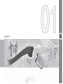
SAFETY
I
nf
or
mat
i
onPr
ovi
dedby:
01 Safety
01
Occupant safety
Volvo's concern for safety
Safety is the Volvo cornerstone. Our concern
dates back to 1927 when the first Volvo rolled
off the production line. Three-point seat belts
(a Volvo invention), safety cages, and energyabsorbing impact zones were designed into
Volvo vehicles long before it was fashionable
or required by government regulation. We will
not compromise our commitment to safety. We
continue to seek out new safety features and
to refine those already in our vehicles. You can
help. We would appreciate hearing your suggestions about improving automobile safety.
We also want to know if you ever have a safety
concern with your vehicle. Call us in the U.S.
at: 800-458-1552 or in Canada at:
800-663-8255.
Occupant safety reminders
How safely you drive doesn't depend on how
old you are but rather on:
• How well you see.
• Your ability to concentrate.
• How quickly you make decisions under
stress to avoid an accident.
The tips listed below are suggestions to help
you cope with the ever changing traffic environment.
• Never drink and drive.
• If you are taking any medication, consult
your physician about its potential effects
on your driving abilities.
• Take a driver-retraining course.
• Have your eyes checked regularly.
• Keep your windshield and headlights
clean.
• Replace wiper blades when they start to
leave streaks.
• Take into account the traffic, road, and
weather conditions, particularly with
regard to stopping distance.
• Never send text messages while driving.
• Refrain from using or minimize the use of a
cell phone while driving.
Reporting safety defects in the U.S.
If you believe that your vehicle has a
defect which could cause a crash or
could cause injury or death, you
should immediately inform the
National Highway Traffic Safety
Administration (NHTSA) in addition to
notifying Volvo Cars of North America, LLC. If NHTSA receives similar
complaints, it may open an investigaI
nf
or
mat
i
onPr
ovi
dedby:
18
tion, and if it finds that a safety defect
exists in a group of vehicles, it may
order a recall and remedy campaign.
However, NHTSA cannot become
involved in individual problems
between you, your retailer, or Volvo
Cars of North America, LLC. To contact NHTSA, you may either call the
Auto Safety Hotline toll-free at
1-888-327-4236
(TTY: 1-800-424-9153) or write to:
NHTSA, U.S. Department of Transportation, Washington D.C. 20590.
You can also obtain other information
about motor vehicle safety from:
http://www.safercar.gov
Volvo strongly recommends that if
your vehicle is covered under a service campaign, safety or emission
recall or similar action, it should be
completed as soon as possible.
Please check with your local retailer
or Volvo Cars of North America, LLC
if your vehicle is covered under these
conditions.
01 Safety
Occupant safety
01
NHTSA can be reached at:
Internet:
http://www.nhtsa.gov
Telephone:
1-888-DASH-2-DOT
(1-888-327-4236).
Reporting safety defects in Canada
If you believe your vehicle has a defect that
could cause a crash or could cause injury or
death, you should immediately inform Transport Canada in addition to notifying Volvo Cars
of Canada Corp.
Transport Canada can be contacted at:
1-800-333-0510
Teletypewriter (TTY): 613 990-4500
Fax: 1-819-994-3372
Mailing Address: Transport Canada - Road
Safety, 80 rue Noël, Gatineau, (Quebec) J8Z
0A1
I
nf
or
mat
i
onPr
ovi
dedby:
19
01 Safety
01
Seat belts
Using seat belts
sioners are triggered in situations where the
airbags deploy. The front seat belts also
include a tension reducing device which, in the
event of a collision, limits the peak forces exerted by the seat belt on the occupant.
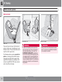
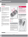
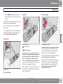
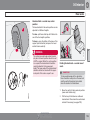
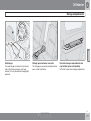
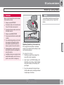
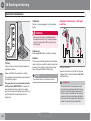
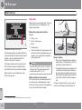
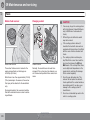
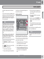
Buckling a seat belt
G020104
Pull the belt out far enough to insert the latch
plate into the receptacle until a distinct click is
heard. The seat belt retractor is normally
"unlocked" and you can move freely, provided
that the shoulder belt is not pulled out too far.
Adjusting the seat belt
Volvo, the inventor of the three-point seat belt,
urges you and all occupants of your vehicle to
wear seat belts and ensure that children are
properly restrained, using an infant, car, or
booster seat determined by age, weight and
height.
The seat belt retractor will lock up in the following situations:
•
•
•
•
•
if the belt is pulled out rapidly
See also page 38 for information about using
a seat belt's ALR/ELR function to anchor a
child seat.
during braking and acceleration
When wearing the seat belt remember:
if the vehicle is leaning excessively
when driving in turns
• The belt should not be twisted or turned.
• The lap section of the belt must be posi-
if the Automatic Locking Retractor/Emergency Locking Retractor (ALR/ELR) is activated
• Make sure that the shoulder belt is rolled
Volvo also believes no child should sit in the
front seat of a vehicle.
tioned low on the hips (not pressing against
the abdomen).
up into its retractor and that the shoulder
and lap belts are taut.
Unbuckling the seat belt
To remove the seat belt, press the red section
on the seat belt receptacle. Before exiting the
vehicle, check that the seat belt retracts fully
after being unbuckled. If necessary, guide the
belt back into the retractor slot.
Most states and provinces make it mandatory
for occupants of a vehicle to use seat belts.
Seat belt pretensioners
The seat belts are equipped with pretensioners
that reduce slack in the belts. These pretenI
nf
or
mat
i
onPr
ovi
dedby:
20
NOTE
Each seat belt (except for the driver's belt)
is equipped with the ALR/ELR function,
which is designed to help keep the seat belt
taut. ALR/ELR activates if the seat belt is
pulled out as far as possible. If this is done,
a sound from the seat belt retractor will be
audible, which is normal, and the seat belt
will be pulled taut and locked in place. This
function is automatically disabled when the
seat belt is unbuckled and fully retracted.
01 Safety
Seat belts
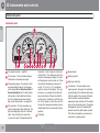
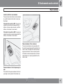
The seat belt reminder consists of an audible
signal, an indicator light above the rearview
mirror, and a symbol in the instrument panel
that alert the driver and front seat passenger if
their seat belts are not fastened.
WARNING
•
Never use a seat belt for more than one
occupant.
•
Never wear the shoulder portion of the
belt under the arm, behind the back or
otherwise out of position. Such use
could cause injury in the event of an
accident.
•
Seat belts lose much of their strength
when exposed to violent stretching and
should be replaced after any collision,
even if they appear to be undamaged.
•
Never repair the belt yourself; have this
work done by an authorized Volvo service technician only.
•
Any device used to induce slack into the
shoulder belt portion of the three-point
belt system will have a detrimental
effect on the amount of protection available to you in the event of a collision.
•
The seat back should not be tilted too
far back. The shoulder belt must be taut
in order to function properly.
•
Do not use child safety seats or child
booster cushions/backrests in the front
passenger's seat. We also recommend
that children who have outgrown these
devices sit in the rear seat with the seat
belt properly fastened.
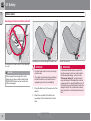
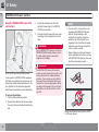
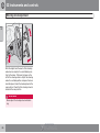
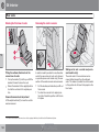
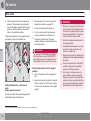
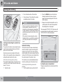
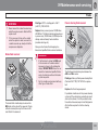
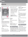
Seat belt use during pregnancy
G020105
Seat belt reminder
01
The seat belt should always be worn during
pregnancy. But it is crucial that it be worn in the
correct way. The diagonal section should wrap
over the shoulder then be routed between the
breasts and to the side of the belly. The lap
section should lay flat over the thighs and as
low as possible under the belly. It must never
be allowed to ride upward. Remove all slack
from the belt and insure that it fits close to the
body without any twists.
As a pregnancy progresses, pregnant drivers
should adjust their seats and steering wheel
such that they can easily maintain control of the
vehicle as they drive (which means they must
be able to easily operate the foot pedals and
I
nf
or
mat
i
onPr
ovi
dedby:
21
01 Safety
01
Seat belts
steering wheel). Within this context, they
should strive to position the seat with as large
a distance as possible between their belly and
the steering wheel.
Child seats
Please see page 38 for information on securing child seats with the seat belts.
Seat belt maintenance
Check periodically that the seat belts are in
good condition. Use water and a mild detergent for cleaning. Check seat belt mechanism
function as follows: attach the seat belt and pull
rapidly on the strap.
I
nf
or
mat
i
onPr
ovi
dedby:
22
01 Safety
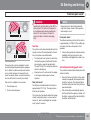
Supplemental Restraint System
Supplemental Restraint System (SRS)
Where applicable, a text message
will also be displayed when the
SRS warning light illuminates. If
this warning symbol is not functioning properly, the general warning symbol illuminates and a text message will
be displayed.
WARNING
G027284
•
SRS warning light
As an enhancement to the three-point seat
belts, your Volvo is equipped with a Supplemental Restraint System (SRS). Volvo's SRS
consists of seat belt pretensioners, front airbags, side impact airbags, the occupant
weight sensor, and inflatable curtains. All of
these systems are monitored by the SRS control module. An SRS warning light in the instrument panel (see the illustration) illuminates
when the ignition key is turned to position I, II,
or III, and will normally go out after approximately 7 seconds if no faults are detected in
the system.
•
If the SRS warning light stays on after
the engine has started or if it illuminates
while you are driving, have the vehicle
inspected by a trained and qualified
Volvo service technician as soon as
possible.
Never try to repair any component or
part of the SRS yourself. Any interference in the system could cause malfunction and serious injury. All work on
these systems should be performed by
an authorized Volvo service technician.
01
WARNING
If your vehicle has been subjected to flood
conditions (e.g. soaked carpeting/standing
water on the floor of the vehicle) or if your
vehicle has become flood-damaged in any
way, do not attempt to start the vehicle or
put the key in the ignition before disconnecting the battery (see below). This may
cause airbag deployment which could result
in personal injury. Have the vehicle towed to
a trained and qualified Volvo service technician for repairs.
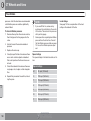
Automatic transmission:
Before attempting to tow the vehicle, use
the following procedure to override the
shiftlock system to move the gear selector
to the neutral position:
1. Switch off the ignition for at least
10 minutes and disconnect the battery.
2. Wait at least one minute.
3. Insert the key in the ignition and turn it
to position II
4. Press firmly on the brake pedal.
5. Move the gear selector from P (Park) to
the N (Neutral) position.
I
nf
or
mat
i
onPr
ovi
dedby:
23
01 Safety
01
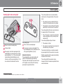
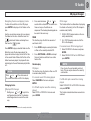
Front airbags
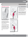
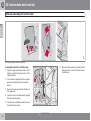
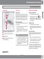
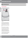
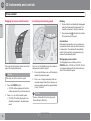
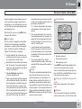
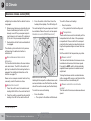
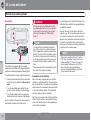
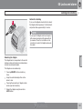
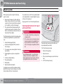
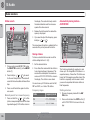
• The driver's side front airbag is folded and
The front airbag system
located in the steering wheel hub.
• The passenger's side front airbag is folded
behind a panel located above the glove
compartment.
The front airbags supplement the three-point
seat belts. For these airbags to provide the
protection intended, seat belts must be worn
at all times.
The front airbag system includes gas generators surrounded by the airbags, and deceleration sensors that activate the gas generators,
causing the airbags to be inflated with nitrogen
gas.
Location of the passenger's side front airbag
As the movement of the seats' occupants compresses the airbags, some of the gas is expelled at a controlled rate to provide better cushioning. Both seat belt pretensioners also
deploy, minimizing seat belt slack. The entire
process, including inflation and deflation of the
airbags, takes approximately one fifth of a second.
The location of the front airbags is indicated by
SRS AIRBAG embossed on the steering wheel
pad and above the glove compartment, and by
decals on both sun visors and on the front and
far right side of the dash.
I
nf
or
mat
i
onPr
ovi
dedby:
24
•
The airbags in the vehicle are designed
to be a SUPPLEMENT to–not a replacement for–the three-point seat belts. For
maximum protection, wear seat belts at
all times. Be aware that no system can
prevent all possible injuries that may
occur in an accident.
•
Never drive a vehicle with your hands on
the steering wheel pad/airbag housing.
•
The front airbags are designed to help
prevent serious injury. Deployment
occurs very quickly and with considerable force. During normal deployment
and depending on variables such as
seating position, one may experience
abrasions, bruises, swellings, or other
injuries as a result from deployment of
one or both of the airbags.
•
When installing any accessory equipment, make sure that the front airbag
system is not damaged. Any interference in the system could cause malfunction.
G031006
G020111
WARNING
01 Safety
Front airbags
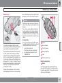
Front airbag deployment
• The front airbags are designed to deploy
during certain frontal or front-angular collisions, impacts, or decelerations, depending on the crash severity, angle, speed and
object impacted. The airbags may also
deploy in certain non-frontal collisions
where rapid deceleration occurs.
•
• The SRS sensors, which trigger the front
airbags, are designed to react to both the
impact of the collision and the inertial
forces generated by it, and to determine if
the intensity of the collision is sufficient for
the seat belt pretensioners and/or airbags
to be deployed.
However, not all frontal collisions activate the
front airbags.
• If the collision involves a nonrigid object
(e.g., a snow drift or bush), or a rigid, fixed
object at a low speed, the front airbags will
not necessarily deploy.
• Front airbags do not normally deploy in a
side impact collision, in a collision from the
rear or in a rollover situation.
• The amount of damage to the bodywork
does not reliably indicate if the airbags
should have deployed or not.
•
•
NOTE
Customer Care Center
Deployment of front airbags occurs only
one time during an accident. In a collision where deployment occurs, the airbags and seat belt pretensioners activate. Some noise occurs and a small
amount of powder is released. The
release of the powder may appear as
smoke-like matter. This is a normal
characteristic and does not indicate fire.
1 Volvo Drive
Volvo's front airbags use special sensors that are integrated with the front
seat buckles. The point at which the airbag deploys is determined by whether
or not the seat belt is being used, as well
as the severity of the collision.
Collisions can occur where only one of
the airbags deploys. If the impact is less
severe, but severe enough to present a
clear injury risk, the airbags are triggered at partial capacity. If the impact is
more severe, the airbags are triggered
at full capacity.
01
P.O. Box 914
Rockleigh, New Jersey 07647
1-800-458-1552
www.volvocars.us
In Canada
Volvo Cars of Canada Corp.
National Customer Service
175 Gordon Baker Road
North York, Ontario M2H 2N7
1-800-663-8255
www.volvocars.ca
Should you have questions about any component in the SRS system, please contact a
trained and qualified Volvo service technician
or Volvo customer support:
In the USA
Volvo Cars of North America, LLC
I
nf
or
mat
i
onPr
ovi
dedby:
25
01 Safety
01
Front airbags
WARNING
•
Never drive with the airbags deployed.
The fact that they hang out can impair
the steering of your vehicle. Other
safety systems can also be damaged.
•
The smoke and dust formed when the
airbags are deployed can cause skin
and eye irritation in the event of prolonged exposure.
G032934
•
WARNING
Do not use child safety seats or child
booster cushions/backrests in the front
passenger's seat. We also recommend
that occupants under 4 feet 7 inches
(140 cm) in height who have outgrown
these devices sit in the rear seat with the
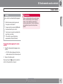
seat belt fastened.
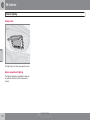
Airbag decal on the outside of both sun visors
Passenger's side airbag decal
I
nf
or
mat
i
onPr
ovi
dedby:
26
•
Children must never be allowed in the
front passenger's seat.
•
Occupants in the front passenger's seat
must never sit on the edge of the seat,
sit leaning toward the instrument panel
or otherwise sit out of position.
•
The occupant's back must be as upright
as comfort allows and be against the
seat back with the seat belt properly
fastened.
•
Feet must be on the floor, e.g., not on
the dash, seat or out of the window.
01 Safety
Front airbags
01
WARNING
•
No objects or accessory equipment,
e.g. dashboard covers, may be placed
on, attached to, or installed near the air
bag hatch (the area above the glove
compartment) or the area affected by
airbag deployment.
•
There should be no loose articles, e.g.
coffee cups, on the floor, seat, or dashboard area.
•
Never try to open the airbag cover on
the steering wheel or the passenger's
side dashboard. This should only be
done by a trained and qualified Volvo
service technician.
Failure to follow these instructions can
result in injury to the vehicle occupants.
I
nf
or
mat
i
onPr
ovi
dedby:
27
01 Safety
01
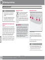
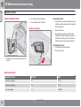
Occupant Weight Sensor
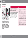
Disabling the passenger's side front
airbag
not inflate) the passenger's side front airbag
under certain conditions.
The OWS works with sensors that are part of
the front passenger's seat and seat belt. The
sensors are designed to detect the presence of
a properly seated occupant and determine if
the passenger's side front airbag should be
enabled (may inflate) or disabled (will not
inflate).
The OWS will disable (will not inflate) the passenger's side front airbag when:
G027050
• the front passenger's seat is unoccupied,
Occupant Weight Sensor (OWS) indicator light
Volvo recommends that ALL occupants (adults
and children) shorter than 4 feet 7 inches
(140 cm) be seated in the rear seat of any vehicle with a passenger's side front airbag, and be
properly restrained. Children should always be
seated in child restraints appropriate for their
size and weight. For child safety recommendations, see page 37.
The Occupant Weight Sensor (OWS) is
designed to meet the regulatory requirements
of Federal Motor Vehicle Safety Standard
(FMVSS) 208 and is designed to disable (will
or has small/medium objects in the front
seat,
• the system determines that an infant is
present in a rear-facing infant seat that is
installed according to the manufacturer's
instructions,
• the system determines that a small child is
present in a forward-facing child restraint
that is installed according to the manufacturer's instructions,
• the system determines that a small child is
present in a booster seat,
• a front passenger takes his/her weight off
of the seat for a period of time,
• a child or a small person occupies the front
passenger's seat.
I
nf
or
mat
i
onPr
ovi
dedby:
28
The OWS uses a PASSENGER AIRBAG OFF
indicator lamp which will illuminate and stay on
to remind you that the passenger's side front
airbag is disabled. The PASSENGER AIRBAG
OFF indicator lamp is located in the overhead
console, near the base of the rearview mirror.
NOTE
The PASSENGER AIRBAG OFF indicator
lamp will illuminate for a short period of time
when the ignition is turned on to confirm it
is functional. When the front passenger's
seat is not occupied (empty seat) or in the
event that the passenger's side front airbag
is enabled (may inflate), the PASSENGER
AIRBAG OFF indicator lamp will be off.
However, if a fault is detected in the system:
• The OWS indicator light will stay on
• The SRS warning light (see page 23) will
come on and stay on
• The message PASS. AIRBAG OFF
SERVICE URGENT will be displayed in the
information display.
01 Safety
Occupant Weight Sensor
WARNING
•
If a fault in the system is detected and
indicated as explained, be aware that
the passenger's side front airbag will
not deploy in the event of a collision.
•
In this case, the safety systems and
Occupant Weight Sensor should be
inspected by a trained and qualified
Volvo service technician as soon as
possible.
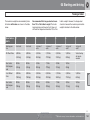
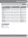
illuminate and stay on to remind you that the
passenger's side front airbag is disabled (see
the following table).
Passenger's seat
occupancy status
OWS indicator light
status
Passenger's side
front airbag status
Seat unoccupied
OWS indicator light
is not
lit
Passenger's
side front
airbag disabled
Seat occupied by low
weight
occupant/
objectA
OWS indicator light
lights
up
Passenger's
side front
airbag disabled
Seat occupied by
heavy occupant/object
OWS indicator light
is not
lit
Passenger's
side front
airbag enabled
WARNING
•
•
Never try to open, remove, or repair any
components in the OWS system. This
could result in system malfunction.
Maintenance or repairs should only be
carried out by a trained and qualified
Volvo service technician.
The front passenger's seat should not
be modified in any way. This could
reduce pressure on the seat cushion,
which might interfere with the OWS system's function.
A
The OWS is designed to disable (will not inflate)
the passenger's side front airbag when a rear
facing infant seat, a forward-facing child
restraint, or a booster seat is detected. The
PASSENGER AIRBAG OFF indicator lamp will
Volvo recommends that children always be properly
restrained in appropriate child restraints in the rear seats.In
rare situations when the seat belt is not properly fastened,
some child restraints may not be detected by the OWS
because there is very little weight on the vehicle seat cushion. In these cases the passenger's side front airbag may be
disabled, but the PASSENGER AIRBAG OFF indicator lamp
will not be lit. Do not assume that the passenger's side front
airbag is disabled unless the PASSENGER AIRBAG OFF
01
indicator lamp is lit. Make sure the child restraint is properly
installed (turn the vehicle off, remove the child restraint from
the vehicle and reinstall the restraint following the child
restraint manufacturer's instructions) and that the
PASSENGER AIRBAG OFF indicator lamp is on, or move
the child restraint to the rear seat.
The OWS is designed to enable (may inflate)
the passenger's side front airbag in the event
of a collision anytime the system senses that a
person of adult size is sitting properly in the
front passenger's seat. The PASSENGER
AIRBAG OFF indicator lamp will be off and
remain off.
If a person of adult size is sitting in the front
passenger's seat, but the PASSENGER
AIRBAG OFF indicator lamp is on, it is possible
that the person isn't sitting properly in the seat.
If this happens:
1. Turn the vehicle off and ask the person to
place the seat back in an upright position.
2. Have the person sit upright in the seat,
centered on the seat cushion, with the person's legs comfortably extended.
3. Restart the vehicle and have the person
remain in this position for about two
minutes. This will allow the system to
detect that person and enable the passenger's frontal airbag.
4. If the PASSENGER AIRBAG OFF indicator
lamp remains on even after this, the person
should be advised to ride in the rear seat.
I
nf
or
mat
i
onPr
ovi
dedby:
29
01 Safety
01
Occupant Weight Sensor
This condition reflects limitations of the OWS
classification capability. It does not indicate
OWS malfunction.
WARNING
•
Modifications
If you are considering modifying your vehicle in
any way to accommodate a disability, for
example by altering or adapting the driver's or
front passenger's seat(s) and/or airbag systems, please contact Volvo at:
In the USA
•
The seat belt should never be wrapped
around an object on the front passenger's seat. This could interfere with the
OWS system's function.
•
The front passenger's seat belt should
never be used in a way that exerts more
pressure on the passenger than normal.
This could increase the pressure exerted on the weight sensor by a child, and
could result in the airbag being enabled,
which might cause it to deploy in the
event of a collision, thereby injuring the
child.
Volvo Cars of North America, LLC
Customer Care Center
1 Volvo Drive
P.O. Box 914 Rockleigh,
New Jersey 07647
1-800-458-1552
In Canada
Volvo Cars of Canada Corp.
National Customer Service
No objects that add to the total weight
on the seat should be placed on the
front passenger's seat. If a child is
seated in the front passenger's seat
with any additional weight, this extra
weight could cause the OWS system to
enable the airbag, which might cause it
to deploy in the event of a collision,
thereby injuring the child.
WARNING
Keep the following points in mind with
respect to the OWS system. Failure to follow
these instructions could adversely affect the
system's function and result in serious injury
to the occupant of the front passenger's
seat:
•
The full weight of the front seat passenger should always be on the seat cushion. The passenger should never lift
him/herself off the seat cushion using
the armrest in the door or the center
console, by pressing the feet on the
floor, by sitting on the edge of the seat
cushion, or by pressing against the
backrest in a way that reduces pressure
on the seat cushion. This could cause
OWS to disable the front passenger's
side airbag.
•
Do not place any type of object on the
front passenger's seat in such a way
that jamming, pressing, or squeezing
occurs between the object and the front
seat, other than as a direct result of the
correct use of the Automatic Locking
Retractor/Emergency Locking Retractor (ALR/ELR) seat belt (see page 38).
•
No objects should be placed under the
front passenger's seat. This could interfere with the OWS system's function.
175 Gordon Baker Road
North York, Ontario M2H 2N7
1-800-663-8255
I
nf
or
mat
i
onPr
ovi
dedby:
30
01 Safety
Side impact protection airbags
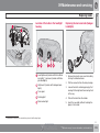
Side impact airbags – front seats only
01
NOTE
SIPS airbag deployment (one airbag) occurs
only on the side of the vehicle affected by
the impact. The airbags are not designed to
deploy in all side impact situations.
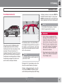
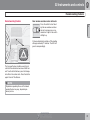
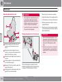
Components in the SIPS airbag system
G025315
G020118
This SIPS airbag system consists of gas generators and side airbag modules built into the
outboard sides of both front seat backrests.
Driver's side SIPS airbag
Location of the side impact (SIPS) airbag
As an enhancement to the structural side
impact protection built into your vehicle, the
vehicle is also equipped with Side Impact Protection System (SIPS) airbags.
G025316
The SIPS airbag system is designed to help
increase occupant protection in the event of
certain side impact collisions. The SIPS airbags are designed to deploy only during certain side-impact collisions, depending on the
crash severity, angle, speed and point of
impact.
Passenger's side SIPS airbag
I
nf
or
mat
i
onPr
ovi
dedby:
31
01 Safety
01
Side impact protection airbags
WARNING
•
The SIPS airbag system is a supplement to the structural Side Impact Protection System and the three-point seat
belt system. It is not designed to deploy
during collisions from the front or rear of
the vehicle or in rollover situations.
•
The use of seat covers on the front seats
may impede SIPS airbag deployment.
•
No objects, accessory equipment or
stickers may be placed on, attached to
or installed near the SIPS airbag system
or in the area affected by SIPS airbag
deployment.
•
Never try to open or repair any components of the SIPS airbag system. This
should be done only by a trained and
qualified Volvo service technician.
•
In order for the SIPS airbag to provide
its best protection, both front seat
occupants should sit in an upright position with the seat belt properly fastened.
•
Failure to follow these instructions can
result in injury to the occupants of the
vehicle in the event of an accident.
I
nf
or
mat
i
onPr
ovi
dedby:
32
01 Safety
Inflatable Curtain
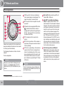
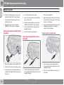
The Inflatable Curtain (IC)
01
will deploy, whereas, in some cases, ONLY the
Inflatable Curtain will deploy. In cases where
BOTH the Inflatable Curtain and the SIPS-bag
deploy, deployment will occur simultaneously.
NOTE
If the Inflatable Curtain deploys, it remains
inflated for approximately 5 seconds.
G027047
G027048
WARNING
This system consists of inflatable curtains
located along the sides of the roof liners,
stretching from the front side windows to the
rear edge of the rear side windows. It is
designed to help protect the heads of the occupants of the front seats and the occupants of
the outboard rear seating positions, including
the outboard passenger in the third row of
seats in certain side impact collisions.
The inflatable curtains in the Volvo XC90 are
also designed to help protect the occupants of
the vehicle in a roll-over situation, and to help
prevent them from being thrown from the vehicle if a roll-over occurs.
NOTE
•
The IC system is a supplement to the
Side Impact Protection System. It is not
designed to deploy during collisions
from the front or the rear of the vehicle.
•
Never try to open or repair any components of the IC system. This should be
done only by a trained and qualified
Volvo service technician.
•
Never hang heavy items from the ceiling
handles. This could impede deployment
of the Inflatable curtain.
The Inflatable Curtains extend to protect all
three rows of seats.
By design, the IC system deploys only on the
side of the vehicle affected by the impact.
However, in certain side impacts, or in a rollover situation, BOTH the Inflatable Curtains
and the Side Impact Airbag System (SIPS-bag)
I
nf
or
mat
i
onPr
ovi
dedby:
33
01 Safety
01
Inflatable Curtain
WARNING
In order for the IC to provide its best protection, both front seat occupants and both
outboard rear seat occupants should sit in
an upright position with the seat belt properly fastened; adults using the seat belt and
children using the proper child restraint system. Only adults should sit in the front seats.
Children must never be allowed in the front
passenger seat. See page 38 for guidelines. Failure to follow these instructions can
result in injury to the vehicle occupants in an
accident.
I
nf
or
mat
i
onPr
ovi
dedby:
34
01 Safety
Whiplash Protection System
01
G020347
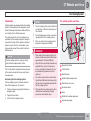
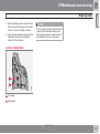
Whiplash Protection System (WHIPS) – front seats only
The Whiplash Protection System (WHIPS) consists of specially designed hinges and brackets
on the front seat backrests designed to help
absorb some of the energy generated in a collision from the rear (when the vehicle is "rearended").
In the event of a collision of this type, the hinges
and brackets of the front seat backrests are
designed to change position slightly to allow
the backrest/head restraint to help support the
occupant's head before moving slightly rearward. This movement helps absorb some of
the forces that could result in whiplash.
WARNING
•
The WHIPS system is designed to supplement the other safety systems in
your vehicle. For this system to function
properly, the three-point seat belt must
be worn. Please be aware that no system can prevent all possible injuries that
may occur in an accident.
•
The WHIPS system is designed to function in certain collisions from the rear,
depending on the crash severity, angle
and speed.
WARNING
Occupants in the front seats must never sit
out of position. The occupant's back must
be as upright as comfort allows and be
against the seat back with the seat belt
properly fastened.
I
nf
or
mat
i
onPr
ovi
dedby:
35
01 Safety
01
Whiplash Protection System
WARNING
•
WARNING
Any contact between the front seat backrests and the folded rear seat could impede
the function of the WHIPS system. If the rear
seat is folded down, the occupied front
seats must be adjusted forward so that they
do not touch the folded rear seat.
Do not attempt to service any component in the WHIPS system yourself.
G020125
G020126
•
WARNING
If your vehicle has been involved in a
rear-end collision, the front seat backrests must be inspected by a trained
and qualified Volvo service technician,
even if the seats appear to be undamaged. Certain components in the
WHIPS system may need to be
replaced.
I
nf
or
mat
i
onPr
ovi
dedby:
36
•
Boxes, suitcases, etc. wedged behind
the front seats could impede the function of the WHIPS system.
•
If the rear seat backrests are folded
down, cargo must be secured to prevent it from sliding forward against the
front seat backrests in the event of a
collision from the rear. This could interfere with the action of the WHIPS system.
01 Safety
Child safety
Children should be seated safely
Volvo recommends the proper use of restraint
systems for all occupants including children.
Remember that, regardless of age and size, a
child should always be properly restrained in a
vehicle.
Your vehicle is also equipped with ISOFIX/
LATCH attachments, which make it more convenient to install child seats.
Some restraint systems for children are
designed to be secured in the vehicle by lap
belts or the lap portion of a lap-shoulder belt.
Such child restraint systems can help protect
children in vehicles in the event of an accident
only if they are used properly. However, children could be endangered in a crash if the child
restraints are not properly secured in the vehicle. Failure to follow the installation instructions
for your child restraint can result in your child
striking the vehicle's interior in a sudden stop.
Holding a child in your arms is NOT a suitable
substitute for a child restraint system. In an
accident, a child held in a person's arms can
be crushed between the vehicle's interior and
an unrestrained person. The child could also be
injured by striking the interior, or by being ejected from the vehicle during a sudden maneuver
or impact. The same can also happen if the
infant or child rides unrestrained on the seat.
Other occupants should also be properly
restrained to help reduce the chance of injuring
or increasing the injury of a child.
All states and provinces have legislation governing how and where children should be carried in a vehicle. Find out the regulations existing in your state or province. Recent accident
statistics have shown that children are safer in
rear seating positions than front seating positions when properly restrained. A child restraint
system can help protect a child in a vehicle.
Here's what to look for when selecting a child
restraint system:
• It should have a label certifying that it
meets applicable Federal Motor Vehicle
Safety Standards (FMVSS 213) – or in Canada, CMVSS 213.
• Make sure the child restraint system is
approved for the child's height, weight and
development – the label required by the
standard or regulation, or instructions for
infant restraints, typically provide this information.
01
When a child has outgrown the child safety
seat, you should use the rear seat with the
standard seat belt fastened. The best way to
help protect the child here is to place the child
on a cushion so that the seat belt is properly
located on the hips, see page 47. Legislation
in your state or province may mandate the use
of a child seat or cushion in combination with
the seat belt, depending on the child's age and/
or size. Please check local regulations.
A specially designed and tested booster cushion and backrest can be obtained from your
Volvo retailer.
USA: for children weighing 33 – 80 lbs.
(15 – 36 kg) and 38 – 54 inches (97 – 137 cm)
in height
Canada: for children weighing 40 – 80 lbs.
(18 – 36 kg) and 40 – 54 inches (102 – 137 cm)
in height
• In using any child restraint system, we urge
you to carefully look over the instructions
that are provided with the restraint. Be sure
you understand them and can use the
device properly and safely in this vehicle. A
misused child restraint system can result in
increased injuries for both the infant or
child and other occupants in the vehicle.
I
nf
or
mat
i
onPr
ovi
dedby:
``
37
01 Safety
01
Child safety
WARNING
•
•
Do not use child safety seats or child
booster cushions/backrests in the front
passenger's seat. We also recommend
that children under 4 feet 7 inches
(140 cm) in height who have outgrown
these devices sit in the rear seat with the
seat belt fastened.
On hot days, the temperature in the
vehicle interior can rise very quickly.
Exposure to these high temperatures
for even a short period of time can
cause heat-related injury or death.
Small children are particularly at risk.
Child seat should always be registered. See
page 39 for more information.
When attaching the seat belt to a child
seat:
1. Attach the seat belt to the child seat
according to the child seat manufacturer's
instructions.
2. Pull the seat belt out as far as possible.
3. Insert the seat belt latch plate into the
buckle (lock) in the usual way.
4. Release the seat belt and pull it taut around
the child seat.
A sound from the seat belt retractor will be
audible at this time and is normal. The belt will
now be locked in place. This function is automatically disabled when the seat belt is
unlocked and the belt is fully retracted.
WARNING
Automatic Locking Retractor/
Emergency Locking Retractor (ALR/
ELR)
To make child seat installation easier, each
seat belt (except for the driver's belt) is equipped with a locking mechanism to help keep the
seat belt taut.
Do not use child safety seats or child
booster cushions/backrests in the front
passenger's seat. We also recommend that
children who have outgrown these devices
sit in the rear seat with the seat belt properly
fastened.
Volvo's recommendations
Why does Volvo believe that no child should sit
in the front seat of a car? It's quite simple really.
A front airbag is a very powerful device
designed, by law, to help protect an adult.
Because of the size of the airbag and its speed
of inflation, a child should never be placed in
the front seat, even if he or she is properly belted or strapped into a child safety seat. Volvo
has been an innovator in safety for over seventy-five years, and we'll continue to do our
part. But we need your help. Please remember
to put your children in the back seat, and
buckle them up.
Volvo has some very specific
recommendations:
• Always wear your seat belt.
• Airbags are a SUPPLEMENTAL safety
device which, when used with a threepoint seat belt can help reduce serious
injuries during certain types of accidents.
Volvo recommends that you do not disconnect the airbag system in your vehicle.
• Volvo strongly recommends that everyone
in the vehicle be properly restrained.
• Volvo recommends that ALL occupants
(adults and children) shorter than 4 feet
7 inches (140 cm) be seated in the back
I
nf
or
mat
i
onPr
ovi
dedby:
38
01 Safety
Child safety
01
seat of any vehicle with a front passenger
side airbag.
• Drive safely!
Child restraint registration and recalls
Registering a child restraint
Child restraints could be recalled for safety
reasons. You must register your child restraint
to be reached in a recall. To stay informed
about child safety seat recalls, be sure to fill out
and return the registration card that comes
with new child restraints.
Child restraint recall information is readily available in both the U.S. and Canada. For recall
information in the U.S., call the U.S. Government's Auto Safety Hotline at 1-800-424-9393.
In Canada, visit Transport Canada's Child
Safety website at http://www.tc.gc.ca/
roadsafety/childsafety/menu.htm.
I
nf
or
mat
i
onPr
ovi
dedby:
39
01 Safety
01
Child restraint systems
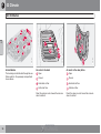
Convertible seat
G026489
G026503
G026491
Child restraints
Booster cushion
Infant seat
There are three main types of child restraint
systems: infant seats, convertible seats, and
booster cushions. They are classified according to the child's age and size.
The following section provides general information on securing a child restraint using a
three-point seat belt. Refer to page 48 and
page 50 for information on securing a child
restraint using ISOFIX/LATCH lower anchors
and/or top tether anchorages.
WARNING
A child seat should never be used in the
front passenger seat of any vehicle with a
front passenger airbag – not even if the
PASSENGER AIRBAG OFF symbol near
the rear-view mirror is illuminated (on vehicles equipped with Occupant Weight Sensor). If the severity of an accident were to
cause the airbag to inflate, this could lead to
serious injury or death to a child seated in
this position.
I
nf
or
mat
i
onPr
ovi
dedby:
40
WARNING
Always refer to the child restraint manufacturer's instructions for detailed information
on securing the restraint.
01 Safety
Child restraint systems
01
WARNING
•
When not in use, keep the child restraint
system secured or remove it from the
passenger compartment to help prevent it from injuring passengers in the
event of a sudden stop or collision.
•
A small child's head represents a considerable part of its total weight and its
neck is still very weak. Volvo recommends that children up to age 4 travel,
properly restrained, facing rearward. In
addition, Volvo recommends that children should ride rearward facing, properly restrained, as long as possible.
I
nf
or
mat
i
onPr
ovi
dedby:
41
01 Safety
01
Infant seats
Positioning the seat belt through the infant seat
Do not place the infant seat in the front passenger's seat
NOTE
Refer to page 48 and page 50 for information on securing a child restraint using
ISOFIX/LATCH lower anchors and/or top
tether anchorages.
WARNING
•
An infant seat must be in the rear-facing
position only.
•
The infant seat should not be positioned
behind the driver's seat unless there is
adequate space for safe installation.
1. Place the infant seat in the rear seat of the
vehicle.
2. Attach the seat belt to the infant seat
according to the manufacturer's instructions.
I
nf
or
mat
i
onPr
ovi
dedby:
42
G026492
G026493
G026417
Securing an infant seat with a seat belt
Fasten the seat belt
WARNING
A child seat should never be used in the
front passenger seat of any vehicle with a
front passenger airbag – not even if the
"Passenger airbag off" symbol near the
rear-view mirror is illuminated (on vehicles
equipped with Occupant Weight Sensor). If
the severity of an accident were to cause the
airbag to inflate, this could lead to serious
injury or death to a child seated in this position.
01 Safety
Infant seats
3. Fasten the seat belt by inserting the latch
plate into the buckle (lock) until a distinct
click is audible.
01
WARNING
It should not be possible to move the child
restraint (child seat) more than 1 in. (2.5 cm)
in any direction along the seat belt path.
G026494
The infant seat can be removed by unbuckling
the seat belt and letting it retract completely.
Pull out the shoulder section of the seat belt
4. Pull the shoulder section of the seat belt
out as far as possible to activate the belt's
automatic locking function.
Ensure that the seat is securely in place
NOTE
The locking retractor will automatically
release when the seat belt is unbuckled and
allowed to retract fully.
5. Press the infant seat firmly in place, let the
seat belt retract and pull it taut. A sound
from the seat belt retractor's automatic
locking function will be audible at this time
and is normal. The seat belt should now be
locked in place.
6. Push and pull the infant seat along the seat
belt path to ensure that it is held securely
in place by the seat belt.
I
nf
or
mat
i
onPr
ovi
dedby:
43
01 Safety
01
Convertible seats
WARNING
WARNING
Always use a convertible seat that is suitable for the child's age and size. See the convertible seat manufacturer's recommendations.
A small child's head represents a considerable part of its total weight and its neck is
still very weak. Volvo recommends that children up to age 4 travel, properly restrained,
facing rearward. In addition, Volvo recommends that children should ride rearward
facing, properly restrained, as long as possible.
G026420
Securing a convertible seat with a seat
belt
G026503
Do not place the convertible seat in the front passenger's seat
NOTE
Route the seat belt through the convertible seat
G026500
Refer to page 48 and page 50 for information on securing a child restraint using
ISOFIX/LATCH lower anchors and/or top
tether anchorages.
Fasten the seat belt
Convertible seats can be used in either a forward or rearward-facing position, depending
on the age and size of the child.
I
nf
or
mat
i
onPr
ovi
dedby:
44
01 Safety
Convertible seats
01
WARNING
•
Convertible child seats should be installed in the rear seat only.
•
A rear-facing convertible seat should not
be positioned behind the driver's seat
unless there is adequate space for safe
installation.
G026501
1. Place the convertible seat in the rear seat
of the vehicle.
2. Attach the seat belt to the convertible seat
according to the manufacturer's instructions.
3. Fasten the seat belt by inserting the latch
plate into the buckle (lock) until a distinct
click is audible.
4. Pull the shoulder section of the seat belt
out as far as possible to activate the belt's
automatic locking function.
Pull out the shoulder section of the seat belt
NOTE
Ensure that the seat is securely in place
WARNING
The locking retractor will automatically
release when the seat belt is unbuckled and
allowed to retract fully.
5. Press the convertible seat firmly in place,
let the seat belt retract and pull it taut. A
sound from the seat belt retractor's automatic locking function will be audible at
this time and is normal. The seat belt
should now be locked in place.
It should not be possible to move the child
restraint (child seat) more than 1 in. (2.5 cm)
in any direction along the seat belt path.
The convertible seat can be removed by
unbuckling the seat belt and letting it retract
completely.
6. Push and pull the convertible seat along
the seat belt path to ensure that it is held
securely in place by the seat belt.
I
nf
or
mat
i
onPr
ovi
dedby:
45
01 Safety
01
Convertible seats
WARNING
A child seat should never be used in the
front passenger seat of any vehicle with a
front passenger airbag – not even if the
PASSENGER AIRBAG OFF symbol near
the rear-view mirror is illuminated (on vehicles equipped with Occupant Weight Sensor). If the severity of an accident were to
cause the airbag to inflate, this could lead to
serious injury or death to a child seated in
this position.
I
nf
or
mat
i
onPr
ovi
dedby:
46
01 Safety
Booster cushions
01
Position the child correctly on the booster cushion
Booster cushions are recommended for children who have outgrown convertible seats.
1. Place the booster cushion in the rear seat
of the vehicle.
2. With the child properly seated on the
booster cushion, attach the seat belt to or
around the cushion according to the manufacturer's instructions.
3. Fasten the seat belt by inserting the latch
plate into the buckle (lock) until a distinct
click is audible.
G026517
G026513
Securing a booster cushion
Positioning the seat belt
4. Ensure that the seat belt is pulled taut and
fits snugly around the child.
WARNING
•
The hip section of the three-point seat
belt must fit snugly across the child's
hips, not across the stomach.
•
The shoulder section of the three-point
seat belt should be positioned across
the chest and shoulder.
•
The shoulder belt must never be placed
behind the child's back or under the
arm.
I
nf
or
mat
i
onPr
ovi
dedby:
47
01 Safety
01
ISOFIX/LATCH lower anchors
Using the ISOFIX/LATCH lower child
seat anchors
3. Fasten the attachment on the child
restraint's lower straps to the ISOFIX/
LATCH lower anchors.
NOTE
•
The rear seat's center position is not
equipped with ISOFIX/LATCH lower
anchors. When installing a child
restraint in this position, attach the
restraint's top tether strap (if it is so
equipped) to the top tether anchorage
point and secure the restraint with the
vehicle's center seat belt.
•
Always follow your child seat manufacturer's installation instructions, and use
both ISOFIX/LATCH lower anchors and
top tethers whenever possible.
4. Firmly tension the lower child seat straps
according to the manufacturer's instructions.
WARNING
G015268
Volvo's ISOFIX/LATCH anchors conform to
FMVSS/CMVSS standards. Always refer to
the child restraint system's manual for
weight and size ratings.
ISOFIX/LATCH lower child restraint anchors
Lower anchors for ISOFIX/LATCH-equipped
child seats are located in the second row, outboard seats, hidden below the backrest cushions. Symbols on the seat back upholstery
mark the anchor positions (see the illustration).
WARNING
The ISOFIX/LATCH lower child restraint
anchors are only intended for use with child
seats positioned in the outboard seating
positions. These anchors are not certified
for use with any child restraint that is positioned in the center seating position. When
securing a child restraint in the center seating position, use only the vehicle's center
seat belt.
To access the anchors:
1. Put the child restraint in position.
G031682
2. Kneel on the child restraint to press down
the seat cushion and locate the anchors by
feel.
Fasten the attachment correctly to the ISOFIX/
LATCH lower anchors
I
nf
or
mat
i
onPr
ovi
dedby:
48
01 Safety
ISOFIX/LATCH lower anchors
01
WARNING
Be sure to fasten the attachment correctly
to the anchor (see the illustration). If the
attachment is not correctly fastened, the
child restraint may not be properly secured
in the event of a collision.
I
nf
or
mat
i
onPr
ovi
dedby:
49
01 Safety
01
Top tether anchors
Top tether anchors
WARNING
Be sure to fasten the child tether attachment
correctly to the anchor. If it is not correctly
fastened, the child seat may not be properly
restrained in the event of a collision.
• Firmly tension the top tether strap accord-
WARNING
•
Never route a top tether strap over the
top or around the head restraint. It
should always be routed under the head
restraint.
•
Child restraint anchorages are designed
to withstand only those loads imposed
by correctly fitted child restraints. Under
no circumstances are they to be used
for adult seat belts or harnesses. The
anchorages are not able to withstand
excessive forces on them in the event of
collision if full harness seat belts or adult
seat belts are installed to them. An adult
who uses a belt anchored in a child
restraint anchorage runs a great risk of
suffering severe injuries should a collision occur.
•
Do not install rear speakers that require
the removal of the top tether anchors or
interfere with the proper use of the top
tether strap.
G027032
ing to the child restraint manufacturer's
instructions. Tension the top tether strap
only after the lower anchor straps or the
seat belt have been firmly tensioned.
For securing the child restraint to ISOFIX/
LATCH lower anchors,see page 48.
Top tether anchorage points
Your vehicle is equipped with child restraint top
tether anchorages in all second row seat positions (second-row seats only in 7-seat models).
Using the top tether anchorages
• Place the child restraint on the rear seat.
• Route the top tether strap under the head
restraint and fasten its attachment to the
anchorage.
I
nf
or
mat
i
onPr
ovi
dedby:
50
01 Safety
Integrated booster cushion
Integrated booster cushion*
over the child's collarbone, not over the child's
neck. If using a booster cushion does not result
in proper positioning of the shoulder strap,
then the child should be placed in a properly
secured child restraint (see page 37 for information). The shoulder belt must never be
placed behind the child's back or under the
arm.
01
WARNING
• Death or serious injury can
occur.
• Follow all instructions on the booster
cushion and in the vehicle's owner's
manual.
• Make sure the booster cushion is securely locked before
the child is seated.
• Use this booster cushion only with chil-
G031071
dren who weigh between 33 and 80 lbs
(15 and 36 kg) and whose height is
between 38 and 54 in (97 and 137 cm).
In Canada, Transport Canada's weight
recommendation is 40 – 80 lbs
(18 - 36 kg).
Volvo's own integrated booster cushion has
been specially designed to help safeguard a
child seated in the rear seat. When using an
integrated booster cushion, the child must be
secured with the vehicle's three-point seat
belt.
•
Use this booster cushion only with children
who weigh between 33 and 80 lbs (15 and
36 kg) and whose height is between 38 and
54 in (97 and 137 cm). In Canada, Transport
Canada's weight recommendation is
40 – 80 lbs (18 – 36 kg).
In the event of a collision while the integrated booster cushion was occupied,
the entire booster cushion and seat belt
must be replaced. The booster cushion
should also be replaced if it is badly
worn or damaged in any way. This work
should be performed by an authorized
Volvo retailer only.
NOTE
The booster cushion is designed to raise the
child higher, so that the shoulder strap crosses
Canada only: This cushion may be referred
to as a built-in booster cushion.
I
nf
or
mat
i
onPr
ovi
dedby:
* Option/accessory, for more information, see Introduction.
51
01 Safety
01
Integrated booster cushion
G030708
The booster cushion must be pressed down
before the backrest can be folded down.
Raising
1. Pull the handle at the front of the cushion
forward.
2. Move the seat belt latch aside before raising the cushion.
3. With both hands push the cushion rearward.
4. Push the cushion until it locks in place.
Lowering
1. Pull the handle at the front of the cushion
forward.
2. Pull the seat forward and press it down
until it locks in place.
I
nf
or
mat
i
onPr
ovi
dedby:
52
01 Safety
01
I
nf
or
mat
i
onPr
ovi
dedby:
53
Instrument overview................................................................................
Instrument panel.....................................................................................
Information display..................................................................................
Center console buttons...........................................................................
Steering wheel adjustment.....................................................................
Lighting panel..........................................................................................
Manually unlocking the fuel filler door....................................................
Left-side steering wheel lever.................................................................
Right-side steering wheel lever...............................................................
Hazard warning flashers.........................................................................
Trip computer..........................................................................................
Cruise control..........................................................................................
12-volt sockets.......................................................................................
Hood/tailgate..........................................................................................
Power windows.......................................................................................
Mirrors.....................................................................................................
Power moonroof.....................................................................................
56
58
62
64
66
67
70
71
72
75
76
78
80
81
82
84
87
HomeLink® Wireless Control System*.................................................... 89
I
nf
or
mat
i
onPr
ovi
dedby:
54
* Option/accessory, for more information, see Introduction.
INSTRUMENTS AND CONTROLS
I
nf
or
mat
i
onPr
ovi
dedby:
02 Instruments and controls
Instrument overview
02
I
nf
or
mat
i
onPr
ovi
dedby:
56
02 Instruments and controls
Instrument overview
Control panel in the driver's door
Headlights/Parking lights
Horn
Panel vents
Cruise control buttons in steering wheel
Display
Turn signals, High/low beams, READ-button
Parking brake pedal
Odometer/Trip odometer/Cruise control
indicator
Parking brake release handle
Speedometer
Reading lights
Turn signal indicator lights
Courtesy light
Tachometer
Moonroof control*
Ambient temperature gauge, clock, gear
indicator
Seat belt reminder
Fuel gauge
G029570
Temperature gauge
02
Rearview mirror
Central locking button
Indicator and warning symbols
Lockout switch for rear seat power windows
Panel vents
Power window controls
Glove compartment
Door mirror controls
Hazard warning flashers
Audio system
Climate system controls
Windshield wiper/washer lever
Audio control buttons in steering wheel
Instrument panel
I
nf
or
mat
i
onPr
ovi
dedby:
* Option/accessory, for more information, see Introduction.
57
02 Instruments and controls
Instrument panel
Instrument panel
G027133
02
Turn signal indicators – right/left
Text window – The text window displays
information and warning messages.
Temperature gauge – The pointer should
be approximately midway on the gauge
when driving. Do not drive the vehicle if
the warning light is on. The text window
will provide you with additional information. If the engine temperature remains
high, check coolant level – see page 222.
Trip odometer – The trip odometers are
used for measuring shorter distances. The
right-hand digit gives tenth of a mile/kilometer. Press the button for more than
2 seconds to reset. Change between trip
odometers 1 and 2 using one short press
on the button. – The display presents information and warning messages, the ambient temperature, and the clock, etc. When
the ambient temperature is between 23°
and 36 °F (–5° and +2 °C), a snowflake
symbol is shown in the display. This symbol serves as a warning for possible slippery road surfaces. Please note that this
symbol does not indicate a fault with your
car. At low speeds, or when the car is not
moving, the temperature readings may be
slightly higher than the actual ambient temperature.
Odometer
I
nf
or
mat
i
onPr
ovi
dedby:
58
Speedometer
Warning symbol
High beam indicator
Tachometer – The tachometer shows
engine speed in thousands of revolutions
per minute (rpm). Do not drive continuously
with the needle in the red area of the dial,
which indicates maximum allowable
engine rpm range. Instead, shift to a higher
gear or slow the vehicle down. The engine
management system will automatically
prevent excessively high engines speeds.
This will be noticeable as a pronounced
unevenness in engine speed.
02 Instruments and controls
Instrument panel
Gear and driving mode indicator – The currently selected driving mode is displayed
here. If you use the Geartronic function on
the automatic transmission, the currently
selected gear will be displayed.
Clock/set button – Turn the button to set
the clock.
Fuel gauge – see page 290 for fuel tank
volume. When the warning light in the
gauge comes on, the vehicle should be
refueled as soon as possible. The trip computer section (see page 76) provides
more information on fuel level and consumption.
This symbol shines as a red or yellow light depending on the nature
of the information displayed.
G027134
Ambient temperature gauge – This display
indicates the air temperature outside your
vehicle. A "snowflake" symbol in the text
window is displayed when the temperature
is in the range of 23 – 36 °F (–5 – +2 °C).
Please note that this symbol does not indicate a fault with your vehicle. At low
speeds or when the vehicle is not moving,
the temperature readings may be slightly
higher than the actual ambient temperature.
Warning/information symbol in center of
the instrument panel
This shows that the symbols are functioning.
When the engine starts, all symbols go out. If
the engine is not started within 5 seconds, all
symbols except CHECK ENGINE and
go out. Certain symbols may not have their
functions illustrated, depending on the vehicle's equipment. The symbol for the parking
brake goes out when the parking brake is
released.
02
Red symbol – Stop the vehicle as soon as
possible in a suitable location and read the
message shown in the text window. The symbol and accompanying text will remain on until
the fault has been corrected.
Yellow symbol – Follow the instructions
shown in the text window. The text can be
erased by pressing the READ button (see
page 62), or will disappear automatically after
two minutes.
NOTE
When the message TIME FOR REGULAR
SERVICE is displayed, the text can be
erased and the yellow symbol light can be
turned off by pressing the READ button.
The text will disappear and the symbol light
will go out automatically after two minutes.
Indicator and warning symbols – The indicator and warning symbols1light up when
you turn the ignition key to the driving position (position II) before starting.
1
On certain engines, the symbol for low oil pressure is not used. Instead, a text warning is provided in the information display, see page 220.
I
nf
or
mat
i
onPr
ovi
dedby:
59
02 Instruments and controls
Instrument panel
Seat belt reminder
This symbol lights up to indicate
that the driver has not fastened his/
her seat belt.
02
If the BRAKE and ABS warning lights come
on at the same time, this could indicate a
fault in the brake system.
• Stop the vehicle in a suitable place and
switch off the engine.
Supplemental Restraint System (SRS)
If this light comes on while the
vehicle is being driven, or remains
on for longer than approximately
10 seconds after the vehicle has
been started, the SRS system's
diagnostic functions have detected a fault in a
seat belt lock or pretensioner, a front airbag,
side impact airbag, and/or an inflatable curtain.
Have the system(s) inspected by a trained and
qualified Volvo service technician as soon as
possible.
BRAKE – Brake failure warning light
If the light comes on while driving or braking,
stop immediately, open the hood and check
the brake fluid level in the reservoir. see
page 223.
Canadian models are equipped
with this warning light.
2
This light will be on when the parking brake
(hand brake) is applied. The parking brake
pedal is located on the left side of the driver's
footwell, see page 80 for more information.
Canadian models are equipped
with this symbol.
• Restart the engine.
• If both warning lights go off, no further
action is required.
• If both lights are still on after the engine has
been restarted, switch off the engine again
and check the brake fluid level (see
page 223 for the location of the brake fluid
reservoir).
If the brake fluid level is above the MIN mark,
drive carefully to a trained and qualified Volvo
service technician and have the brake system
inspected.
WARNING
If the fluid level is below the MIN mark in the
reservoir or if a Brake failure – Service
urgent message is displayed in the text
window: DO NOT DRIVE. Have the vehicle
towed to a trained and qualified Volvo service technician and have the brake system
inspected.
Oil pressure warning light2
If the light comes on while driving, stop the vehicle and then
stop the engine immediately and
check the engine oil level, see
page 62. If the light stays on after
restart, have the vehicle towed to the nearest
trained and qualified Volvo service technician.
After hard driving, the light may come on occasionally when the engine is idling. This is normal, provided it goes off when the engine
speed is increased.
Generator warning light
On certain engines, the symbol for low oil pressure is not used. Instead, a text warning is provided in the information display, see page 62.
I
nf
or
mat
i
onPr
ovi
dedby:
60
PARK BRAKE Parking brake applied
If the light comes on while the
engine is running, have the charging system checked.
02 Instruments and controls
Instrument panel
Rear fog light
This light indicates that the fog
light is on.
CHECK ENGINE Malfunction indicator
light
On-Board Diagnostics II (OBDII): As you drive,
a computer called "OBDII" monitors your vehicle's engine, transmission, electrical and emission systems. The CHECK ENGINE light will
light up if the computer senses a condition that
potentially may need correcting. When this
happens, please have your vehicle checked by
a trained and qualified Volvo service technician
as soon as possible.
A CHECK ENGINE light may have many causes. Sometimes, you may not notice a change
in your vehicle's behavior. Even so, an uncorrected condition could hurt fuel economy,
emission cleanliness, and driveability.
Extended driving without correcting the cause
could even damage other components in your
vehicle.
Canadian models are equipped
with this symbol for the Malfunction Indicator Light.
ABS (Anti-lock brake system)
If the warning light comes on, there
is a malfunction of the ABS system
(the standard braking system will
still function). The vehicle should
be driven to a trained and qualified
Volvo service technician for inspection. See
page 153 for additional information.
02
DSTC system
The Dynamic Stability and Traction
Control system (DSTC) is
explained in greater detail on page
157.
Tire pressure monitoring light
See page 200 for more information on this function.
Turn signal indicator – trailer (certain
models)
If you are towing a trailer, this light
will flash simultaneously with the
turn signals on the trailer. If the
light does not flash when signaling,
neither the trailer's turn signals nor
the vehicle's turn signals are functioning.
I
nf
or
mat
i
onPr
ovi
dedby:
61
02 Instruments and controls
Information display
Message in the text windows
When a warning light in the instrument panel
comes on, a message is also displayed in the
text window. After you have read the message,
you can erase it by pressing button A (see illustration).
02
NOTE
function of your choice. Press button A to erase
the warning message.
You can scroll through the stored messages by
pressing button A (see illustration). The text
window can be cleared (the message will be
returned to memory) by pressing button A
again.
G026979
Certain messages cannot be erased until
the condition has been corrected.
If a warning message is displayed when e.g.
you are using the trip computer, this message
must be erased before you can access the
Message
Meaning
BRAKE FAILURE STOP SAFELYA
Stop the car in a safe place and switch off the engine to help prevent the risk of serious damage.
COOLANT LOW STOP ENGINE B
Stop the car in a safe place and switch off the engine to help prevent the risk of serious damage.
BRAKE FLUID LOW SERVICE
URGENT C
Take your vehicle to a trained and qualified Volvo service technician for inspection immediately.
HIGH ENGINE TEMP SEE MANUAL D
Refer to your owner's manual. For additional information, please contact your Volvo retailer.
ABS SERVICE REQUIREDE
Take your vehicle to a trained and qualified Volvo service technician for inspection at your convenience
(but preferably before the next scheduled maintenance service).
I
nf
or
mat
i
onPr
ovi
dedby:
62
02 Instruments and controls
Information display
A
B
C
D
E
Message
Meaning
TIME FOR REGULAR MAINTENANCE
This message will be displayed at 10,000 mile (16,000 km) intervals, after 500 hours of driving or after
12 months, whichever occurs first, to remind the driver that the service interval has been exceeded. The
message will be displayed for 2 minutes each time the vehicle is started until reset by a trained and qualified
Volvo service technician.
DSTC SPIN CONTROL OFF
The stability system's spin control function has been turned off, see page 157 for details.
02
This is one example of several similar texts containing "stop safely"
This is one example of several similar texts containing "stop engine"
This is one example of several similar texts containing "service urgent"
This is one example of several similar texts containing "see manual"
This is one example of several similar texts containing "service required"
I
nf
or
mat
i
onPr
ovi
dedby:
63
02 Instruments and controls
Center console buttons
G026944
02
Active Bending Lights*
Rear seat air conditioning*
The beams of these headlights
adjust laterally to help light up a
curve according to movements
of the steering wheel when the
vehicle is turning. This function
is activated automatically when
the engine is started and can be deactivated/
reactivated by pressing the button. The indicator light in the button is on when the function is
activated, also see page 67.
This button controls the
optional rear seat air conditioning system.
* Option/accessory, for more information, see Introduction.
Press the button and release it
to fold the door mirrors in or
out. On certain models, when
the button is pressed, there
may be a long pause before the
mirrors move. Pressing the button again during this pause may erase your first
button press. If this happens, wait ten seconds
and press the button one more time.
The mirrors cannot be adjusted during the first
ten seconds after they have been folded out.
I
nf
or
mat
i
onPr
ovi
dedby:
64
Folding door mirrors*
02 Instruments and controls
Center console buttons
Auxiliary lights
NOTE
If the door mirrors have been inadvertently
pushed out of position (in a car wash, parking lot, etc.) manually return them to normal
position. If mirror adjustment does not seem
to operate after manual folding, reset the
folding mirrors as follows:
•
•
•
•
Turn the ignition key to position II.
Press the button to fold both mirrors in.
NOTE
02
The 12-volt sockets can be
used to plug in certain accessories such as cell phones, etc.
The ignition key must be in
position I (or higher) for the auxiliary socket to function.
Press the button again to fold the mirrors out to their normal position.
This system provides an audible warning when the vehicle is
being parked or if it is driven
close to a person or object. For
more information see
page 159.
For more information on this
function, see page 132.
12-volt sockets
Manually fold the mirror(s) to the normal
position.
Park Assist*
Power child locks*
This button is used to switch on
auxiliary lights (if installed). A
light in the button will light up to
indicate that the auxiliary lights
are illuminated.
The maximum current consumption is 10A
(120W) if only one of the 12-volt sockets is in
use. If both the front and rear sockets are used
at the same time, the maximum current consumption per socket is 7.5A (90W).
NOTE
The auxiliary sockets can also be used for
cigarette lighters, which are available as
accessories at your Volvo retailer.
The system activates automatically when
the engine is started, and can be deactivated by pressing this button (e.g. when
towing a trailer) or reactivated if necessary.
I
nf
or
mat
i
onPr
ovi
dedby:
* Option/accessory, for more information, see Introduction.
65
02 Instruments and controls
Steering wheel adjustment
G026999
02
Both the height and the reach of the steering
wheel can be adjusted to a comfortable position for the driver. Pull down the lever on the
left of the steering column. Adjust the steering
wheel to a suitable position and press the lever
back into place to lock the steering wheel in the
new position. Check that the steering wheel is
locked in the new position.
WARNING
Never adjust the steering wheel while driving.
I
nf
or
mat
i
onPr
ovi
dedby:
66
02 Instruments and controls
Lighting panel
Pos.
Headlights
Lighting
Headlights offA. Pull the leftside steering wheel lever to
flash the high beam headlights.
Parking lights (the LED daytime
running lights in the front spoiler
do not function with the switch
in this positionB)
To illuminate the headlights, the ignition key
must be turned to at least position II and the
headlight switch must be in position
.
02
For information on switching between high and
low beams, see page 71.
Active Bending Lights (ABL)*
Low beam headlights and parking lights on. Pull the left-side
steering wheel lever to toggle
between high and low beams.
Headlight/parking light switch
LED daytime running lights (DRL) in front
spoiler
Rear fog light
Instrument panel lighting
The switch must also be in this
position for the LED daytime
running lights to function (see
page 68).
Fuel filler door unlock button
A
B
On Canadian models, the LED daytime running lights in the
front spoiler will be on.
On Canadian models, the LED daytime running lights in the
front spoiler will remain on.
G020789
If the vehicle is equipped with
the optional Active Bending
Lights (ABL), this feature will
also be activated with the light
switch in this position.
Headlight pattern with the Active Bending Light
function deactivated (left headlight beam) and
activated (right headlight beam)
When this function is activated, the headlight
beams adjust laterally to help light up a curve
according to movements of the steering wheel
(see the right-pointing beam in the illustration).
``
I
nf
or
mat
i
onPr
ovi
dedby:
* Option/accessory, for more information, see Introduction.
67
02 Instruments and controls
Lighting panel
The LED DRLs will also switch off automatically
(and the low beams will switch on) if:
NOTE
02
When driving in daylight conditions, the
headlights will switch off and the daytime
running lights will come on. In darkness, the
daytime running lights will switch off and the
Active Bending Lights will switch on.
• The rear fog light is switched on
• The windshield wipers are switched on for
more than 10 seconds
If the LED DRL function was activated when the
ignition was switched off, it will be active when
the ignition is switched on again.
The ABL function is activated automatically
when the engine is started and the headlight
switch is in the
position and can be
deactivated/reactivated by pressing the button
in the center console (see page 64.
LED Daytime Running Lights (DRL)
To help conserve fuel by reducing the use of
electrical current in the vehicle, DRL can be
used in daylight conditions instead of the low
beam headlights, which consume more electrical current. The daytime running lights are
mounted in the front spoiler and use bright,
electricity-saving LEDs (light emitting diodes).
WARNING
DRL is a driving aid designed to help
conserve electrical current. This system
cannot always determine if the ambient
lighting conditions are sufficient for
switching from low beams to DRL (or
vice versa). It is always the driver's
responsibility to visually determine if the
low beam headlights should be used.
•
As the driver, you have full responsibility
for operating the vehicle in a safe manner.
Press button A to activate automatic DRL in daylight driving conditions
With the headlight switch in the
position
as shown in the illustration, press the button
with the A symbol to activate the automatic
LED daytime running lights in daylight driving
conditions (the indicator light in the button will
illuminate). A light sensor then monitors the
ambient lighting conditions and automatically
switches from LED DRL to the low beam headlights in weaker ambient light (and will switch
back to DRL when the ambient light becomes
brighter). Press the button again (the indicator
light in the switch will turn off) to switch on the
headlights.
I
nf
or
mat
i
onPr
ovi
dedby:
68
•
02 Instruments and controls
Lighting panel
Parking lights
Instrument panel lighting
The front and rear parking lights can be turned
on even when the ignition is switched off.
The instrument panel lighting illuminates when
the ignition key is in position II and the light
switch (1) is in either position
or
.
–
Turn switch (1) to position
.
The license plate lights also illuminate when the
parking lights are switched on.
Rear fog light
The single rear fog light is located in the driver's
side of the vehicle.
The rear fog light will only function in combination with the high/low beam headlights.
1. Turn the ignition key to position II.
2. Press button (3) to turn on the rear fog light.
An indicator light in the button illuminates when
the rear fog light is on.
NOTE
The rear fog light is considerably brighter
than the normal tail lights and should be
used only when conditions such as fog, rain,
snow, smoke or dust reduce visibility for
other vehicles to less than 500 ft.
(150 meters).
–
02
Move the thumb wheel (4) up to increase
brightness or down to decrease brightness.
Unlocking the fuel filler door
Press button (5) when the vehicle is at a standstill to unlock the fuel filler door. Please note
that the fuel filler door will remain unlocked until
the vehicle begins to move forward. An audible
click will be heard when the fuel filler door
relocks.
NOTE
If the fuel filler door does not unlock after the
button has been pressed, drive the vehicle
at a speed of at least 5 mph (8 km/h), stop
the vehicle, and press the button again.
For information on unlocking the fuel filler door
manually, see page 70.
I
nf
or
mat
i
onPr
ovi
dedby:
69
02 Instruments and controls
Manually unlocking the fuel filler door
02
Panel on passenger's side of cargo area
6. Move the catch rearward to unlock the fuel
filler door lock, or move it forward to lock
the filler door.
To manually unlock the fuel filler door
1. Open the upper and lower sections of the
tailgate, and fold up the rear section of the
cargo area floor.
2. If the vehicle is equipped with the optional
grocery bag holder, detach the holder's
bands.
3. Remove the corner panel from the floor of
the cargo area.
4. Open the cover in the side panel by pulling
the tab upward/outward.
5. Pull down the insulating material to access
the fuel filler door motor.
I
nf
or
mat
i
onPr
ovi
dedby:
70
02 Instruments and controls
Left-side steering wheel lever
Lever positions
Turn signals
High/low beam headlights
When turning
Continuous high beams
Move the lever as far up or down as possible
(to position 2) to start the turn signals. The turn
signals will be cancelled automatically by the
movement of the steering wheel, or the lever
can be returned to its initial position by hand.
1. Turn the ignition key to position II.
02
2. With the light switch in position
, (see
page 67) pull the turn signal lever toward
the steering wheel to toggle between high
and low beams.
G026954
When changing lanes
The driver can automatically flash the turn signals 3 times by:
High beam flash
• Moving the turn signal lever up or down to
2. Pull the turn signal lever to position (3). The
high beams will remain on until the lever is
released.
position (1) and releasing it.
• Moving the lever up or down to position (2)
and immediately back to its original position.
Turn signals, lane change position
Turn signals, position for normal turns
High beam flash
NOTE
•
This automatic flashing sequence can
be interrupted by immediately moving
the lever in the opposite direction.
•
If the turn signal indicator flashes faster
than normal, check for a burned-out
turn signal bulb.
Toggle between high and low beams,
Home Safe lighting
1
1. Turn the ignition key to position II.
Home safe lighting
When leaving your vehicle at night, home safe
lighting can illuminate the area in front of the
vehicle.
1. Remove the key from the ignition switch.
2. Pull the turn signal lever as far as possible
toward the steering wheel and release it.
3. Exit the vehicle and lock the doors.
The headlights and parking lights will illuminate
and remain on for 301, 60 or 90 seconds. The
time interval can be changed by a trained and
qualified Volvo service technician.
Factory setting
I
nf
or
mat
i
onPr
ovi
dedby:
71
02 Instruments and controls
Right-side steering wheel lever
Windshield wipers
Intermittent wiper function
With the lever in this position, you
can set the wiper interval by twisting the control ring (1) upward to
increase wiper speed or downward to decrease the speed.
02
Windshield washer/headlight washer
(certain models)
G026953
When the lever is pulled to wash the windshield, high pressure jets mounted in the
bumper will spray the headlights.
CAUTION
•
Use ample washer fluid when washing
the windshield to avoid scratching the
glass. The windshield should be thoroughly wet when the wipers are in operation.
•
Before using the wipers, ice and snow
should be removed from the windshield/rear window. Be sure the wiper
blades are not frozen in place.
Thumb wheel
Rain sensor on/off
Windshield wipers off
If the lever is in the 0 position and
you move it upwards, the wipers
will sweep one stroke at a time for
as long as you hold the lever up.
• To conserve washer fluid in driving condiSingle sweep position
Move the lever slightly upward
from the 0 position for one sweep
of the wipers. The lever returns
automatically to 0 when released.
tions where the windshield washers are
used frequently, the headlights will only be
washed once for every five times the windshield is washed within a 10-minute period.
• A short pull on the lever will wash the windshield only.
I
nf
or
mat
i
onPr
ovi
dedby:
72
• When approximately 1 US quart (1 liter)
remains in the washer fluid reservoir, the
headlights will not be washed when the
lever is pulled to conserve washer fluid for
the windshield. A text message will also be
displayed to remind the driver to fill the
washer fluid reservoir.
Continuous wiper function
Top arrow: normal speed
Bottom arrows: higher speed
02 Instruments and controls
Right-side steering wheel lever
Tailgate wiper/washer
• Move the windshield wiper lever down to
Tailgate wiper and reverse gear
If the front wipers are on and the transmission
is put into reverse gear, the tailgate wiper will
go into intermittent wiping function1.
If the tailgate wiper is already in normal wiping
function, the normal wiping function will continue.
G027127
Rain sensor*
Intermittent wiping: Press the upper
section of the switch
Neutral position: The wiper is switched
off
Normal (continuous) wiping: Press the
lower section of the switch
Move the lever forward to start the tailgate
washer. After washing the rear window, the
wiper will make several additional sweeps.
another position. Moving the lever up will
not deactivate the rain sensor. Doing so
will cause the wipers to sweep the windshield until the lever is released, at which
time the wipers return to rain sensor mode.
02
The rain sensor is also deactivated when the
key is removed from the ignition.
CAUTION
The rain sensor automatically regulates wiper
speed according to the amount of water on the
windshield.
The sensitivity of the sensor can be adjusted
by twisting ring (1) up (the wipers will sweep the
windshield more frequently) or down (the wipers will sweep the windshield less frequently).
The rain sensor should be deactivated when
washing the vehicle in an automatic car
wash, etc. If the rain sensor function is left
on, the wipers will start inadvertently in the
car wash and could be damaged.
Activating the rain sensor:
1. Turn the ignition key to at least position I
and put the windshield wiper lever in position 0.
2. Press button (2), see page 72.
> A light in the button will light up to indicate that the rain sensor is active.
Deactivating the rain sensor:
• Press button (2), see page 72.
or
1
Consult your Volvo retailer if you would like to have this function deactivated.
I
nf
or
mat
i
onPr
ovi
dedby:
* Option/accessory, for more information, see Introduction.
73
02 Instruments and controls
Right-side steering wheel lever
IR-reflecting windshield*
02
Section of the windshield where the IR-coating is
not applied
An optional factory-installed infrared (IR) coating can be applied to the windshield to help
protect the cabin from the sun's heat and the
fading effect of sunlight on upholstery, panels,
etc.
Electronic equipment such as garage door
openers, electronic toll tags and similar devices should not be placed on sections of the
windshield with the IR coating because this
could affect their function and limit their range.
For best performance, place the device on the
section of the windshield without the IR coating
(see the area marked in the illustration).
I
nf
or
mat
i
onPr
ovi
dedby:
74
* Option/accessory, for more information, see Introduction.
02 Instruments and controls
Hazard warning flashers
Hazard warning flashers
Rear window and door mirror defroster
Press the switch to start heating the rear window and door
mirrors to remove ice or condensation. A light in the switch
will light up.
02
A timer automatically switches off the heating
after approximately 12 minutes. The LED will
go out correspondingly.
AM FM
CD
LUM
VO E
POWER
*
3
DEF
5
6
JKL
MNO
8
9
TUV WXYZ
0
#
G027096
2
ABC
1
4
GHI
7
PQRS
The four-way flasher should be used to indicate that the vehicle has become a traffic hazard. To activate the flashers, press the triangular button in the center dash. Press the button
again to turn off the flashers.
NOTE
Regulations regarding the use of the hazard
warning flasher may vary, depending on
where you live.
I
nf
or
mat
i
onPr
ovi
dedby:
75
02 Instruments and controls
Trip computer
• Current speed in mph (Canadian models
Trip computer*
only)
02
• DSTC (see page 157 for detailed information)
G026956
Thumb wheel (used to scroll among the trip
computer menus)
RESET
The trip computer stores information gathered
from several systems in your vehicle and has
four menus that can be displayed in the text
window.
•
•
•
•
Driving distance on current fuel reserve
Average fuel consumption
Current fuel consumption
Average speed
Warning messages from the vehicle's monitoring systems will override the trip computer function. If a warning message is displayed in the text window while you are
using the trip computer, you must acknowledge the message by pressing button A.
Press button A again to return to the trip
computer function.
1. Trip computer controls and functions
The trip computer functions can be accessed
by twisting INFO (B) one step at a time in either
direction. Twisting a final time returns you to
the original function.
The trip computer can be reset (current data
will be erased from system memory) by pressing RESET (button C).
2. Driving distance on current fuel
reserve
This function shows the approximate distance
that can be driven on the fuel remaining in the
tank. The calculation is based on average fuel
consumption during the last 20 miles (30 km)
I
nf
or
mat
i
onPr
ovi
dedby:
76
* Option/accessory, for more information, see Introduction.
When "----" is displayed in the text window,
refuel as soon as possible.
3. Average fuel consumption
NOTE
READ (press to acknowledge/confirm/
erase a message)
of driving and the amount of fuel remaining in
the tank when the reading was taken.
This value indicates fuel consumption since the
last time the trip computer was reset (by pressing RESET, button C). When the engine is
switched off, information on fuel consumption
is stored and remains in system memory until
the RESET (button C) is pressed again.
4. Current fuel consumption
This value indicates the current fuel consumption, based on readings taken once per second. When the vehicle is not moving, "----" will
be displayed.
5. Average speed
This value indicates average speed since the
last time the trip computer was reset (by pressing RESET, button C). When the engine is
switched off, information on average speed is
stored and remains in system memory until the
RESET (button C) is pressed again.
02 Instruments and controls
Trip computer
6. Current speed in miles per hour
(Canadian models only)
02
This function provides the driver with an instantaneous conversion of the vehicle's current
speed from km/h to mph.
NOTE
Trip computer readings may vary slightly
depending on the circumference of the tires
on the vehicle and driving style.
I
nf
or
mat
i
onPr
ovi
dedby:
77
02 Instruments and controls
Cruise control
Engaging the cruise control function
Increasing or decreasing speed
Braking
• Cruise control is automatically disengaged
02
when the brake pedal is depressed. The
currently set speed is stored in memory.
• Pressing resume
will return the vehicle
to the previously set speed.
The cruise control panel is located on the left
side of the steering wheel hub.
NOTE
This does not set the vehicle's speed.
1. Press the CRUISE button.
> CRUISE will be displayed in the information window in the instrument panel.
2. Press + or – to set the current speed.
> CRUISE-ON will be displayed in the
information window in the instrument
panel.
G027139
G027098
Acceleration
Use + or – in the following ways to increase or
decrease the vehicle's speed:
1. Press and hold down + or – until the vehicle
reaches the desired speed.
2. Press + or – for approximately a half second and release the button to increase or
decrease vehicle speed by approximately
1 mph (1.6 km/h).
NOTE
Cruise control will not function at speeds
below 20 mph. (30 km/h).
I
nf
or
mat
i
onPr
ovi
dedby:
78
Momentary acceleration, such as when passing another vehicle, does not affect cruise control operation. The vehicle will automatically
return to the previously set speed when you
release the accelerator pedal.
Disengaging cruise control
To disengage cruise control, press the
CRUISE button. CRUISE or CRUISE-ON will
no longer be displayed in the information window in the instrument panel.
02 Instruments and controls
Cruise control
NOTE
Cruise control is automatically disengaged
if:
•
•
•
•
•
When the brake pedal is depressed.
•
if the vehicle's speed falls below
approximately 20 mph (30 km/h).
the engine is switched off
the gear selector is placed in (N) Neutral
WARNING
Cruise control should not be used in heavy
traffic or when driving on wet or slippery
roads, or when driving on unpaved or
uneven road surfaces. Cruise control may
not maintain set speed on steep downgrades.
02
the wheels start to spin or lock
if an increase in speed is maintained for
more than one minute
Temporarily disengaging the cruise
control
1. Press 0 to temporarily disengage cruise
control.
> CRUISE will be displayed in the information window in the instrument panel.
2. Depress the brake pedal.
causes the vehicle to
Pressing "resume"
return to the previously set speed.
I
nf
or
mat
i
onPr
ovi
dedby:
79
02 Instruments and controls
12-volt sockets
02
These 12 volt sockets can be used to plug in
certain accessories such as cellular telephones, etc.
The ignition key must be in at least position I
for the sockets in the front seat and the optional
socket at the rear of the center console to function.
G028425
The maximum current consumption is 10A
(120W) if only one of the 12-volt sockets in the
passenger compartment is in use. If both the
front and rear sockets are used at the same
time, the maximum current consumption per
socket is 7.5A (90W).
12-volt socket in the cargo compartment
12-volt socket at the rear of the center console*
Fold down the lid to use the socket. This socket
can be used even if the ignition is switched off.
Ashtrays/cigarette lighter
NOTE
•
If the 12-volt sockets are used while the
engine is not running, there is a risk that
the vehicle's battery will be discharged.
•
If the ignition is switched off and a
device drawing more than 0.1 A is connected to a socket, a battery warning
will be displayed in the text window.
•
The covers should be kept on when the
auxiliary sockets are not in use.
The auxiliary socket can also be used to power
a cigarette lighter. Accessory cigarette lighters
and ashtrays can be purchased from your
Volvo retailer.
I
nf
or
mat
i
onPr
ovi
dedby:
80
* Option/accessory, for more information, see Introduction.
12-volt socket in the cargo compartment
02 Instruments and controls
Hood/tailgate
Opening/closing the hood
G026995
WARNING
•
Do not grasp the ribs in the grille when
closing the hood. If your fingers protrude through the grille, they could be
injured on components in the engine
compartment as the grille closes. We
recommend pressing down on the hood
to close it.
•
Check that the hood locks properly
when closed!
To fold down the lower section of the tailgate,
pull handle upward.
02
Opening the tailgate
Opening the hood
1. Pull the lever located under the left side of
the dashboard to release the hood lock.
2. Lift the hood slightly.
3. Press up the release control located under
the front edge of the hood and lift.
To close the hood, place your hand on it and
press down until the hood locks in the closed
position.
To open the upper section of the tailgate, pull
the handle downward.
I
nf
or
mat
i
onPr
ovi
dedby:
81
02 Instruments and controls
Power windows
Power windows
Always remove the ignition key when the
vehicle is unattended.
Make sure that the windows are completely
unobstructed before they are operated.
Never leave children unattended in the vehicle.
To lower: Press down the front edge of the button to the first detent ("stop").
To raise: Lightly pull up the front edge of the
button to the first detent ("stop").
G029571
NOTE
Auto up/down function (front doors only):
Either front door window can be opened or
closed automatically.
Auto down: Press the front part of the button
as far down as possible and release it immediately. To stop the window at any time, pull the
button up.
Auto up: Pull the front part of the button up as
far as possible and release it immediately. To
stop the window at any time, press the button
down.
1
Power window controls
Front windows
Rear windows
NOTE
If a window is obstructed during auto-up, it
will automatically reverse direction and
return to its starting position. If a window is
repeatedly obstructed during auto-up operation, an overload protection circuit breaker
will temporarily halt window function. The
window will return to normal function after a
brief cool-down period.
The power windows will also function after the ignition has been switched off as long as neither of the front doors has been opened.
I
nf
or
mat
i
onPr
ovi
dedby:
82
To reduce buffeting wind noise if the rear
windows are opened, also open the front
windows slightly.
G029572
02
WARNING
The power windows are controlled by buttons
in the arm rests. The ignition switch must be
ON1 (ignition key in position I, II or the engine
running) for the electrically operated windows
to function.
02 Instruments and controls
Power windows
Lockout switch for rear windows
The power rear door windows can be disabled
by a switch located on the driver's door (see
illustration).
02
If the light in the switch is OFF: The rear door
windows can be raised or lowered with the
buttons on the rear door armrests or with the
buttons on the driver's door armrest.
G029574
If the light in the switch is ON: The rear door
windows can only be raised or lowered with the
buttons on the driver's door armrest.
Power windows in the rear doors
G029573
The rear door windows can be operated with
the control on each door and the switch on the
driver's door. If the light in the switch for blocking power windows in the rear doors (located
in the driver's door control panel) is on, the rear
door windows can only be operated from the
driver's door.
Power window on the front passenger's
side
The control for the power window in the front
passenger's seat operates that window only.
I
nf
or
mat
i
onPr
ovi
dedby:
83
02 Instruments and controls
Mirrors
Rearview mirror
or when the engine is running. The compass
can be switched off or on by pressing the inset
button on the rear side of the mirror (see the
inset illustration). This can be done with
straightened paperclip or similar object. The
button is recessed approximately 1 in. (2.5 cm)
in the mirror.
NOTE
This function is automatically switched off
when the gear selector is placed in the
Reverse position.
02
G026660
Rearview mirror with compass*
G026965
Normal position
Night position, reduces glare from following headlights
Autodim function*
The autodim function reacts to headlights from
following traffic and automatically reduces
glare.
The upper left-hand corner of the rearview mirror has an integrated display that shows the
compass direction toward which the car is
pointing. Eight different directions can be displayed: N, NE, E, SE, S, SW, W and NW. The
display shows your car's orientation with
respect to true north.
If the compass is activated, it will be displayed
automatically when the ignition is in postilion II
I
nf
or
mat
i
onPr
ovi
dedby:
84
G026409
To reduce glare from the headlights of following vehicles, use the control to switch between
the normal and night-driving positions.
* Option/accessory, for more information, see Introduction.
Magnetic zones
The earth is divided into 15 magnetic zones.
The compass is initially set for the zone to
which the car was delivered, and should
always be adjusted if the car is driven to a new
magnetic zone. To do so:
1. Switch the ignition to position II.
02 Instruments and controls
Mirrors
3. Press the button repeatedly until the number for the desired zone (1 – 15) is displayed.
Z
O
N
E
C
A
L
Calibrating the compass
3. Using a pen or similar object, hold the button (on the rear side of the mirror)
depressed for at least 6 seconds. "CAL"
will be displayed.
4. Drive slowly in a circle at a maximum speed
of 5 m.p.h. (8 km/h) until CAL is no longer
displayed.
This step can also be done by driving normally until CAL is no longer displayed.
Z
O
N
E
G026950
02
2. Turn off as many electrical devices in the
car as possible to avoid interference with
the compass (e.g. audio system, etc).
NOTE
C
A
L
Power door mirrors
1. Stop the car in a large, open area, away
from traffic.
Calibration is complete.
G029575
2. Press the button on the rear side of the
mirror with straightened paperclip or similar object for approximately 3 seconds until
ZONE is displayed. The number of the current magnetic zone will also be displayed.
The mirror control switches are located on the
driver's door armrest.
Driver's side: Press the L button (a light in the
switch will light up) to activate the adjustment
control and then use this control to adjust the
driver's door mirror.
Passenger's door: Press the R button (a light
in the switch will light up) and then use the
adjustment control to adjust the passenger's
door mirror.
Calibrating the compass
After several seconds, the compass heading
will again be displayed, and the change of
magnetic zones is complete.
After you have adjusted the mirror(s), press the
L or R switch again (the light will go out) to
deactivate the adjustment control.
I
nf
or
mat
i
onPr
ovi
dedby:
85
02 Instruments and controls
Mirrors
For information about the optional folding mirror function see page 64.
02
WARNING
CAUTION
Use the heating function to remove ice,
snow, or mist from the mirrors.
The mirrors should always be adjusted prior
to driving. Objects seen in the passenger's
side wide-angle door mirror are closer than
they appear to be.
Mirror memory function (with the central
locking system)*
If you lock the vehicle and later unlock it with
the same remote key and open the driver's
door, the door mirrors (and the driver's seat)
will automatically move to the position they
were in when you left the vehicle. This feature
will work in the same way with all of the remote
key transmitters (up to 3) that you use with your
vehicle. This feature will not function if you lock
your vehicle with the key.
Water repellent glass
The side door mirrors can be treated
with a water repellent coating. The
symbol to the left indicates these windows
have this coating.
The coating improves vision by causing the
water to run off quickly.
For information on cleaning this type of glass,
see page 208.
I
nf
or
mat
i
onPr
ovi
dedby:
86
* Option/accessory, for more information, see Introduction.
02 Instruments and controls
Power moonroof
Power moonroof
Auto open: Pull the switch as far back as possible (position 4) and release it to automatically
slide open the moonroof to the "comfort"1
position. Pull the switch rearward again to
open the moonroof completely.
02
G007503
G027010
Manual close: Push the switch to position 2
and hold it until the moonroof has closed completely or to the position of your choice.
Tilt position
To operate the moonroof, turn the ignition key
to position I or II, or start the engine. The moonroof can be operated in two ways:
Tilt position
Sliding moonroof
Open: With the moonroof closed, push up the
rear edge of the switch (position 5 in the illustration in the center column).
Close: Pull down and hold the rear edge of the
switch (position 6 in the illustration in the center
column) until the moonroof has closed completely.
Auto close: Push the switch forward as far as
possible (position 1) and release it to automatically close the moonroof.
CAUTION
•
Remove ice and snow before opening
the moonroof.
•
Do not operate the moonroof if it is frozen closed.
•
Never place heavy objects on the
moonroof.
Sliding moonroof
Manual open: Pull the switch rearward to position 3 and hold it until the moonroof has
opened to the position of your choice.
1
A position where the moonroof is not quite fully open, which helps alleviate "rumbling" wind noise.
I
nf
or
mat
i
onPr
ovi
dedby:
87
02 Instruments and controls
Power moonroof
02
•
•
Never allow a child to operate the
moonroof.
•
Never extend any object or body part
through the open moonroof, even if the
vehicle's ignition is completely
switched off.
•
Never leave a child alone in a vehicle.
If the moonroof is obstructed during auto-close
operation, it will automatically reverse direction
and return to its starting position. If the moonroof is repeatedly obstructed during auto-close
operation, an overload circuit breaker will temporarily halt moonroof function. The moonroof
will return to normal function after a brief cooldown period.
G020157
WARNING
Never open/close the moonroof if it is
obstructed in any way when in operation.
Sun visor
The optional moonroof also features a sliding
sun visor. The visor slides open automatically
when the moonroof is opened. The visor must
be closed manually.
WARNING
The moonroof must never be obstructed in
any way when in operation.
I
nf
or
mat
i
onPr
ovi
dedby:
88
02 Instruments and controls
HomeLink® Wireless Control System*
Introduction
G030070
The HomeLink1 Wireless Control System provides a convenient way to replace up to three
hand-held radio-frequency (RF) transmitters
used to activate devices such as gate operators, garage door openers, entry door locks,
security systems, even home lighting. Additional HomeLink information can be found on
the Internet at www.homelink.com or by phoning the hotline at 1–800–355–3515.
1
Programming HomeLink
WARNING
•
If you use HomeLink to open a garage
door or gate, be sure no one is near the
gate or door while it is in motion.
•
When programming a garage door
opener, it is advised to park outside of
the garage.
•
Do not use HomeLink with any garage
door opener that lacks safety stop and
reverse features as required by U.S.
federal safety standards (this includes
any garage door opener model manufactured before April 1, 1982). A garage
door that cannot detect an object - signaling the door to stop and reverse does not meet current U.S. federal
safety standards. For more information,
contact HomeLink at:
www.homelink.com.
Retain the original transmitter of the RF device
you are programming for use in other vehicles
as well as for future HomeLink programming. It
is also suggested that upon the sale of the
vehicle, the programmed HomeLink buttons be
erased for security purposes. Refer to “Resetting HomeLink Buttons” on page 91.
NOTE
02
Some vehicles may require the ignition to be
switched on or be in the “accessories” position for programming and/or operation of
HomeLink. It is also recommended that a
new battery be placed in the hand-held
transmitter of the device being programmed
to HomeLink for quicker training and accurate transmission of the radio-frequency
signal. The HomeLink buttons must be reset
first. When this has been completed, Homelink is in learning mode so that you can perform programming.
1. Position the end of your hand-held transmitter 1–3 inches (5–14 cm) away from the
HomeLink button you wish to program
while keeping the indicator light in view.
2. Simultaneously press and hold both the
chosen HomeLink and hand-held transmitter buttons until the HomeLink indicator
light changes from a slow to a rapidly blinking light. Now you may release both the
HomeLink and hand-held transmitter buttons.
HomeLink and the HomeLink house are registered trademarks of Johnson Controls, Inc.
I
nf
or
mat
i
onPr
ovi
dedby:
* Option/accessory, for more information, see Introduction.
89
02 Instruments and controls
HomeLink® Wireless Control System*
or “smart” button. This can usually be
found where the hanging antenna wire is
attached to the motor-head unit.
NOTE
02
Some devices may require you to replace
this Programming Step 2 with procedures
noted in the “Gate Operator / Canadian Programming” section. If the HomeLink indicator light does not change to a rapidly blinking light after performing these steps, contact HomeLink at www.homelink.com or by
phoning the hotline at 1–800–355–3515.
3. Firmly press, hold for five seconds and
release the programmed HomeLink button up to two separate times to activate the
door. If the door does not activate, press
and hold the just-trained HomeLink button
and observe the indicator light.
• If the indicator light stays on constantly, programming is complete
and your device should activate when
the HomeLink button is pressed and
released.
• If the indicator light blinks rapidly for
two seconds and then turns to a constant light continue with “Programming” steps 4-6 to complete the programming of a rolling code equipped
device (most commonly a garage door
opener).
4. At the garage door opener receiver (motorhead unit) in the garage, locate the “learn”
5. Firmly press and release the “learn” or
“smart” button. (The name and color of the
button may vary by manufacturer.) There
are 30 seconds to initiate step 6.
6. Return to the vehicle and firmly press, hold
for two seconds and release the programmed HomeLink button. Repeat the
“press/hold/release” sequence a second
time, and, depending on the brand of the
garage door opener (or other rolling code
equipped device), repeat this sequence a
third time to complete the programming
process.
HomeLink should now activate your rolling
code equipped device.
Gate Operator/Canadian Programming
Canadian radio-frequency laws require transmitter signals to “time-out” (or quit) after several seconds of transmission – which may not
be long enough for HomeLink to pick up the
signal during programming. Similar to this
Canadian law, some U.S. gate operators are
designed to “time-out” in the same manner.
If you live in Canada or you are having difficulties programming a gate operator or garage
door opener by using the “Programming” proI
nf
or
mat
i
onPr
ovi
dedby:
90
* Option/accessory, for more information, see Introduction.
cedures, replace “Programming HomeLink”
step 2 with the following:
• Continue to press and hold the HomeLink
button while you press and release every two seconds (“cycle”) your handheld transmitter until the HomeLink indicator light changes from a slow to a rapidly
blinking light. Now you may release both
the HomeLink and hand-held transmitter
buttons.
Proceed with “Programming” step 3 to complete.
Using HomeLink
To operate, simply press and hold the programmed HomeLink button until the trained
device begins to operate (this may take several
seconds). Activation will now occur for the
trained device (i.e., garage door opener, gate
operator, security system, entry door lock,
home/office lighting, etc.). For convenience,
the hand-held transmitter of the device may
also be used at any time. In the event that there
are still programming difficulties or questions,
contact HomeLink at: www.homelink.com or
by phoning the hotline at 1–800–355–3515.
02 Instruments and controls
HomeLink® Wireless Control System*
NOTE
If the ignition is switched off, HomeLink will
function for 30 minutes after the driver's
door has been opened.
Reprogramming a Single HomeLink
Button
NOTE
To program a device to HomeLink using a
HomeLink button previously trained, follow
these steps:
Resetting HomeLink Buttons
1. Press and hold the desired HomeLink button. DO NOT release the button.
Use the following procedure to reset (erase
programming) from the three HomeLink buttons (individual buttons cannot be reset but
can be “reprogrammed” as outlined in the following section):
2. The indicator light will begin to flash after
20 seconds. Without releasing the HomeLink button, proceed with “Programming”
- step 1.
1. Press and hold the two outer HomeLink
buttons until the indicator light begins to
flash.
For questions or comments, contact HomeLink
at: www.homelink.com or phone 1–800–355–
3515.
2. Release both buttons.
> HomeLink is now in the training (or
learning) mode and can be programmed
at any time beginning with “Programming” - step 1.
This device complies with FCC rules part 15
and Industry Canada (IC) RSS-210. Operation
is subject to the following two conditions: (1)
This device may not cause harmful interference, and (2) This device must accept any
interference that may be received including
interference that may cause undesired operation.
2
The transmitter has been tested and complies with FCC and IC rules. Changes or
modifications not expressly approved by
the party responsible for compliance could
void the user’s authority to operate the
device.2
02
The term “IC:” before the certification/registration number only signifies that Industry Canada technical specifications were met.
I
nf
or
mat
i
onPr
ovi
dedby:
* Option/accessory, for more information, see Introduction.
91
Climate control system – general information........................................ 94
Air distribution......................................................................................... 96
Electronic climate control (ECC)............................................................. 98
I
nf
or
mat
i
onPr
ovi
dedby:
92
CLIMATE
I
nf
or
mat
i
onPr
ovi
dedby:
03 Climate
Climate control system – general information
Condensation on the inside of the
windows
Sensors
Acceleration
Keeping the insides of the windows clean will
help reduce the amount of condensation that
forms on the windows. Use a commercial window cleaning agent to clean the windows.
The sunlight sensor on the dashboard and passenger compartment temperature sensor in
the ECC control panel should not be covered
in any way as this could cause incorrect information to be sent to the ECC system.
The air conditioning is momentarily disengaged during full-throttle acceleration.
Ice and snow
Parking the vehicle in warm weather
Always keep the air intake grille at the base of
the windshield free of snow.
If your vehicle has been parked in the sun in
warm weather, opening the windows and
moonroof* for several minutes before driving
will help release the warm air from the passenger compartment. When the engine is running,
close the windows and moonroof and use the
recirculation function for several minutes to
enable the air conditioning to cool the compartment as quickly as possible.
03
Cabin air filter
Replace the cabin air filter with a new one at
the recommended intervals. Please refer to
your Warranty and Service Records Information booklet, or consult a trained and qualified
Volvo service technician for these intervals.
The filter should be replaced more often when
driving under dirty and dusty conditions. The
filter cannot be cleaned and therefore should
always be replaced with a new one.
1
Windows and optional moonroof
The ECC system will function best if the windows and optional moonroof are closed. If you
drive with the moonroof open, we recommend
that you manually adjust the temperature and
blower control (the LED in the AUTO switch
should be off).
Includes the optional rear A/C system
I
nf
or
mat
i
onPr
ovi
dedby:
94
* Option/accessory, for more information, see Introduction.
Climate control maintenance
Special tools and equipment are required to
maintain and carry out repairs on the climate
system. Work of this type should only be done
by a trained and qualified Volvo service technician.
Refrigerant
Volvo cares about the environment. The air
conditioning system in your vehicle contains a
CFC-free refrigerant – R134a (HFC134a). This
substance will not deplete the ozone layer. The
approximate amount of R134a contained in the
system is a follows:
6-cylinder engine
Single A/C system: 1.5 lbs (700 g)
Dual1 A/C system: 2.2 lbs (1000 g)
The system also uses PAG oil.
03 Climate
Climate control system – general information
Climate system blower
The climate system blower will be automatically switched off when the engine is not running (even if the ignition key is in position I or
II) to avoid unnecessary battery drain. To activate the blower, turn the control to the desired
setting.
The climate system blower may start automatically during a period of up to approximately
50 minutes after the ignition has been turned
off to remove condensation in the A/C evaporator. It will run for 15 minutes and switch off
automatically.
The following points pertain if the ignition is on
but the engine in not running:
• To restart the blower, turn the control knob
to the setting of your choice.
•
After approximately 2 minutes, the blower
speed will be reduced to avoid battery
drain.
03
You can reset the blower speed at any time.
Please be aware that the system has been
designed to reduce the blower's speed again
after 2 minutes, until the engine is started.
If the battery becomes drained:
• LOW BATTERY, FAN IS REDUCED will
Passenger compartment blower
Approximately 50 minutes after the ignition is
turned off, the blower may come on automatically, and run for seven minutes, to remove
condensation in the A/C evaporator.
be displayed in the text window in the
instrument panel.
• The yellow warning light in the instrument
panel (see page 58) will also light up.
Blower function to reduce battery drain
The climate system's blower functions normally while the engine is running.
However, when the engine is switched off
(even if the ignition is switched to positions I or
II), the blower control will be automatically
switched off to avoid unnecessary battery
drain.
I
nf
or
mat
i
onPr
ovi
dedby:
95
03 Climate
Air distribution
Air distribution
The incoming air is distributed through the ventilation points in the passenger compartment
shown above.
Air vents in the dash
Air vents in the door pillars
Open
Open
Closed
Closed
Horizontal air flow
Horizontal air flow
Vertical air flow
Vertical air flow
Direct the outer air vents toward the side windows to defrost.
I
nf
or
mat
i
onPr
ovi
dedby:
96
0
G027064
G027044
G027043
03
Direct the outer air vents toward the side windows to defrost.
03 Climate
Air distribution
Ventilated front seats*
For maximum ventilation:
–
Hold down
onds.
for approximately 2 sec-
To gradually decrease ventilation:
–
Press briefly on
.
03
To switch off ventilation:
G030244
–
Hold down
onds.
The ventilation can be used at the same time
as seat heating*, for example, to help dry damp
clothing.
NOTE
Controls for ventilated front seats
The ventilation system consists of fans in the
seats and backrests that draw air through the
seat upholstery. The cooling effect increases
as the air in the passenger compartment
becomes cooler.
The level of ventilation is adjusted on the control panel on the side of the seat. The fans can
be set to three speeds.
for approximately 2 sec-
•
Seat ventilation cannot be started if the
temperature in the passenger compartment is below 41°F (5°C).
•
Seat ventilation should be used with
caution by people who are sensitive to
drafts. A moderate ventilation level
should be set if the function is used for
extended periods.
To start seat ventilation:
–
Press briefly on
.
To gradually increase ventilation:
–
Press briefly on
.
I
nf
or
mat
i
onPr
ovi
dedby:
* Option/accessory, for more information, see Introduction.
97
03 Climate
Electronic climate control (ECC)
Overview
03
AC – (ON/OFF)
Temperature passenger´s side
Recirculation/Multifilter with sensor*
Temperature driver´s side
Recirculation
Blower
AUTO
Blower control for rear climate system*
Air distribution
Passenger compartment temperature sensor
Functions
A/C – ON/OFF
• The air conditioning functions only at tem-
Defroster windshield and side windows
Rear window and door mirrors defroster
peratures above 32°F (0°C).
• While the Defroster function is selected,
Heated front seats*
the air conditioning is temporarily activated
to dehumidify the air, even if you have manually switched the air conditioning off. This
I
nf
or
mat
i
onPr
ovi
dedby:
98
* Option/accessory, for more information, see Introduction.
will only function if the blower is not
switched off.
Press the switch to turn the air conditioning on
or off. The "ON" or "OFF" LED will light up to
indicate if the system is switched on or off.
Other functions will still be regulated automatically (if the AUTO switch is on).
Interior air quality sensor*
Some vehicles are equipped with a multifilter
and air quality sensor. The filter separates
gases and particles, thereby reducing the
amounts of odors and contaminants entering
the vehicle. The air quality sensor detects
increased levels of contaminants in the outside
air. When the air quality sensor detects conta-
03 Climate
Electronic climate control (ECC)
When the ECC system is in the AUTO mode,
the green LED will be on.
Recirculation
Press this switch to engage the recirculation
function (air in the passenger compartment
recirculates – no fresh air enters the compartment). The LED in the switch will light up to
indicate that the function is engaged.
• Use this function if the outside air is contaminated with exhaust gases, smoke, etc
or to heat/cool the vehicle quickly.
• Recirculation should not be used for more
than 15 minutes. If your windows begin to
fog or mist, make sure that the recirculation
function is switched off.
•
Selecting Defroster automatically
switches recirculation off.
• Timer mode activation: (Vehicles equipped
with the Interior Air Quality system have no
timer mode) Press and hold the recirculation button for at least 3 seconds to activate a recirculation timer mode. The amber
LED in the recirculation button will flash 5
times to show that the timer mode is being
activated. In timer mode, each time the
recirculation button is pressed, the climate
control system will recirculate the air in the
passenger compartment for
5 – 12 minutes, depending on the outside
air temperature, and then revert back to
fresh air.
Air distribution
• Timer mode deactivation: Press and hold
03
the recirculation button for 3 seconds. The
amber LED in the recirculation button will
illuminate steadily for 5 seconds to show a
return to "normal" mode.
• In normal mode, when the recirculation
button is pressed, the climate control system will recirculate the air in the passenger
compartment until the recirculation button
is pressed again.
• Timer mode memory: If the vehicle is
turned off while timer mode is active, timer
mode will still be active when the vehicle is
restarted.
AUTO
This function automatically regulates the Electronic Climate Control system so that the
selected temperatures are maintained. The
blower, heating, air distribution (air flow), air
conditioning, and optional air quality sensor
are controlled. If you prefer to manually set any
of these functions, the remaining functions will
still be controlled automatically. Pressing the
AUTO button overrides any settings that were
previously made manually.
I
nf
or
mat
i
onPr
ovi
dedby:
G027267
minated outside air, the air intake closes and
the air inside the passenger compartment is
recirculated, i.e. no outside air enters the vehicle. The filter also cleans recirculated passenger compartment air.
• Air flow to windows
• Air through panel vents
• Air through floor vents
Press AUTO to automatically regulate air flow
or press any combination of the controls
shown in the illustration to manually adjust air
flow. An LED in the switch will light up if an air
flow control has been pressed.
Passenger compartment temperature
sensor
Measures the temperature in the compartment.
Defroster
This function defrosts/deices the windshield
and front side windows. The LED in the switch
``
99
03 Climate
Electronic climate control (ECC)
will light up to indicate that the defrost function
is engaged.
3. Press the switch a third time to turn the
heating off completely. The LED will go off.
• Blower speed increases automatically and
The seat heating for the passenger seat should
be switched off when the seat is not occupied.
the air conditioning will switch on (if not
already on and if the passenger compartment blower is not turned off) to dehumidify the air in the passenger compartment.
03
Heated rear seats (XC90 Executive*)
is engaged.
The climate system will return to its previous
settings when the defroster function is
switched off.
2. Press the switch a second time for comfort
heating. One LED in the switch will be lit.
1
G030976
Button for rear seat heating
Heating for the respective outboard rear seats
can be switched on or off with buttons on either
side of the center console (see the illustration).
To switch on rear seat heating:
–
Press the button.
> The symbol in the button will illuminate.
See also see page 94.
I
nf
or
mat
i
onPr
ovi
dedby:
100
Temperature
Blower control1
This function defrosts/deices the rear window
and door mirrors. The LED in the switch will
light up to indicate that the heating function is
engaged. For additional information on this
function see page 75.
Heated front seats*
Press the button.
> The symbol in the button will go out.
Set the control to the temperature you prefer.
Rear window and door mirror
defrosters
1. Press the switch once for maximum seat
heating. Both LEDs in the switch will be lit.
–
These controls are used to individually set the
temperature for both sides of the passenger
compartment. Please note that the compartment will not be heated or cooled faster by setting the temperature higher or lower than necessary.
• Recirculation will not function while defrost
Never use ice scrapers made of metal as they
can easily scratch the mirror surface.
To switch off rear seat heating:
* Option/accessory, for more information, see Introduction.
Turn the control clockwise to increase or counterclockwise to decrease the blower speed.
Pressing the AUTO switch will automatically
regulate blower speed and override manual
adjustment.
Turning the blower control counterclockwise
until an orange LED comes on will turn both the
blower and the air conditioning off.
Blower control for rear climate
system*
Turn the control to increase or decrease blower
speed.
03 Climate
Electronic climate control (ECC)
Operation
Press to operate the air quality sensor (normal
setting).
or:
Select one of the following three functions by
pressing 1, 2 or 3 times.
03
1. The AUT LED lights. The air quality sensor
is now activated.
2. No LED lights. Recirculation is not activated unless needed to cool the passenger
compartment in a warm climate.
3. The MAN LED lights. Recirculation is now
activated.
Keep in mind the following:
• Make it a rule to have the air quality sensor
activated at all times.
• Recirculation is limited in cold climates to
avoid fogging.
• If window fogging occurs, you should
deactivate the air quality sensor. Also use
the defroster functions for the windshield,
side windows and rear window, see
page 98.
• The filter should be changed at the intervals recommended in the service schedule. However, if the vehicle is used in a
severely contaminated environment, it may
be necessary to change the filter more frequently.
I
nf
or
mat
i
onPr
ovi
dedby:
101
Front seats............................................................................................
Rear seats.............................................................................................
Interior lighting......................................................................................
Storage compartments.........................................................................
Securing cargo......................................................................................
I
nf
or
mat
i
onPr
ovi
dedby:
102
104
108
111
114
119
INTERIOR
I
nf
or
mat
i
onPr
ovi
dedby:
04 Interior
Front seats
Manually adjusted front seats
1. Move the seat as far back as possible.
WARNING
•
•
Do not adjust the seat while driving. The
seat should be adjusted so that the
brake pedal can be depressed fully. In
addition, position the seat as far rearward as comfort and control allow.
Check that the seat is securely locked
into position after adjusting.
4. Without releasing the catches, push the
backrest forward.
5. Move the seat as far forward as possible
so that the head restraint slides under the
glove compartment.
Folding the backrests in the front seat
G027214
04
Front-rear adjustment: lift the bar and
move the seat to the position of your
choice.
Raise/lower the front edge of the seat
cushion*: use the control to pump the front
edge of the cushion up or down.
G014805
Raise/lower seat height: pump the seat up
or down.
Lumbar support: turn the control for firmer
or softer lumbar support.
Backrest tilt: turn the control to adjust the
angle of the backrest.
Control panel for optional power seat (see
page 105 for more information).
The front passenger seat backrest can be
folded to a horizontal position to make room for
a long load. Fold the backrest as follows:
I
nf
or
mat
i
onPr
ovi
dedby:
104
2. Adjust the backrest to the upright position.
3. Lift the catches on the rear of the backrest.
* Option/accessory, for more information, see Introduction.
WARNING
•
When transporting long objects, cover
sharp edges on the load to help prevent
injury to occupants. Secure the load to
help prevent shifting during sudden
stops.
•
When the seat's backrest is returned to
the upright position, push and pull it to
be sure that it is securely locked in this
position.
04 Interior
Front seats
Power seat*
NOTE
The power seats have an overload protector
that activates if a seat is blocked by any
object. If this occurs, switch off the ignition
(key in position 0 ) and wait for a short period
before operating the seat again.
Operation
Driver's seat: The seat can be adjusted if the
ignition key is in position I, II or if the engine is
running. It can also be adjusted as follows with
the ignition off:
• Within several minutes after the driver's
Emergency stop
door has been unlocked from the outside,
has been opened, and remains open.
If the seat accidentally begins to move, press
any of the buttons to stop the seat.
• Within a short period if the driver's door has
04
G027036
just been closed.
• Within a short period if the driver's door has
not been opened after the ignition has
been switched off.
Passenger seat: The seat can only be
adjusted if the ignition key is in position I, II or
if the engine is running.
Power seat adjustment controls
NOTE
Please refer to the following page for information on programming the memory function in the driver's seat.
Seat adjustment
Adjust the power seat(s) with the two controls
at the side of the seat as follows:
Front edge of seat (raise/lower)
Forward – rearward
Rear edge of seat (raise/lower)
Backrest tilt
Remote keyless entry system and the
driver's seat
The remote key transmitter also controls the
position of the electrically operated driver's
seat in the following way:
• Adjust the seat to your preferences.
• When you leave your vehicle, lock it using
the remote key.
The position of the seat is now stored in the
remote key.
Automatic seat adjustment
To move the seat to the position in which you
left it:
I
nf
or
mat
i
onPr
ovi
dedby:
* Option/accessory, for more information, see Introduction.
105
04 Interior
Front seats
2. Open the driver's door within 2 minutes.
WARNING
•
Because the driver's seat can be
adjusted with the ignition off, children
should never be left unattended in the
vehicle.
•
Movement of the seat can be STOPPED
at any time by pressing any button on
the power seat control panel.
•
•
Do not adjust the seat while driving.
The driver's seat will automatically move to the
position in which you left it.
NOTE
•
04
The seat will move to this position even
if someone else has moved it to a different seating position and locked the
vehicle with a different remote key.
•
This feature will work in the same way
with all of the remote key transmitters
(up to 3 ) that you use with your vehicle.
•
This feature will not function if you lock
your vehicle with the key.
•
The seat should be adjusted so that the
brake pedal can be depressed fully. In
addition, position the seat as far rearward as comfort and control allow.
The seat rails on the floor must not be
obstructed in any way when the seat is
in motion.
G027037
1. Unlock the driver's door with the same
remote key (the one used to lock the doors)
Programming the memory
Three different seating and door mirror positions can be stored in the driver seat's memory.
The following example explains how button 1
can be programmed. Buttons 2 and 3 can be
programmed in the same way.
To program (store) a seat position in button 1:
1. Move the seat to the desired position using
the seat adjustment controls (see
page 104).
2. Press and hold down the MEM (memory)
button.
I
nf
or
mat
i
onPr
ovi
dedby:
106
04 Interior
Front seats
3. With the MEM button depressed, press
button 1 briefly to store the seat's current
position.
Massage
Lumbar support
To move the seat to the position that it was in
when button 1 was programmed:
Press and hold down button 1 until the seat
stops moving.
As a safety precaution, the seat will stop automatically if the button is released before the
seat has reached the preset position.
G030183
Front seats*
Massage control
Lumbar support control
Firm massage
G030180
Gentle massage
Massage
G030229
04
Each front seat has a massage function in its
backrest. The massage action is done with air
cushions, which can be adjusted to a firm or
gentle setting. When the setting has been
made, the massaging action is carried out in
cycles as follows: massage 6 minutes – pause
4 minutes – massage 6 minutes, etc.
When the button is in the center position or if
the ignition is in position 0, the massage function is switched off.
The lumbar support uses the same air cushions
as the massage function. The button can be
used to adjust the amount of support in four
directions, as shown in the illustration.
Lumbar support can be only be adjusted when
the massage function is switched off.
A memory function stores the lumbar support
setting and this support will resume after the
massage function has been switched off or
after the vehicle has been parked for an
extended period of time.
Lumbar support
I
nf
or
mat
i
onPr
ovi
dedby:
* Option/accessory, for more information, see Introduction.
107
04 Interior
Rear seats
Removing the center console1
Entering the third row of seats
Tilting the outboard backrests in the
second row of seats:
• Pull up the handle (1), hold it up, and tilt the
backrest forward to move the seat.
• Return the backrest to the upright position
to slide the seat back to its original position.
Forward/rearward seat adjustment
Lift the adjustment bar (2) to move the seat forward or rearward.
1
In order to make it possible to move the center
seat in the second row of seats as far forward
as possible (seven-seat models only), the rear
section of the center console can be removed.
• Pull the handle (see illustration) and lift out
the console.
• To return the console to its original position, slide it back into position until it clicks
into place.
The center console cannot be removed on vehicles equipped with the optional Rear Seat Entertainment System.
I
nf
or
mat
i
onPr
ovi
dedby:
108
G027033
G028445
G027027
04
Sliding center seat – second row (sevenseat models only)
The center seat in the second row can be
moved farther forward than the outboard
seats. This makes it possible for a child seated
in this position to sit closer to the people in the
front seats.
04 Interior
Rear seats
Head restraint – second row, center
position
The head restraint in the center position can be
adjusted to 4 different heights.
To raise – pull the restraint up until it clicks into
one of the four heights positions.
04
WARNING
The center rear seat head restraint should
only be in its lowest position when this seat
is NOT occupied. When the center position
is occupied, the head restraint should be
correctly adjusted to the passenger’s
height. The upper edge of the head restraint
should be at least on a level with the uppermost point of the seat occupant's ear.
G027022
G027015
To lower – press the button at the base of the
support (see illustration) and press the head
restraint down carefully.
Folding the backrests – second row of
seats
CAUTION
To help avoid damage to the upholstery,
there should be no objects on the rear seat
and the seat belt should not be buckled
when the backrest is folded down.
1. Move the seat(s) to their rearmost position
(seven-seat models only).
2. Pull the loop to fold down an outboard
head restraint. Press down the center head
restraint if necessary (see page 109).
I
nf
or
mat
i
onPr
ovi
dedby:
109
04 Interior
Rear seats
3. Pull the handle (1) outward to release the
backrest. The backrests are designed to
lock at a 45 degree angle. Pull the handle
again to continue pressing it down until it
locks in the horizontal position.
To return the backrests to the upright position,
pull handle 1 and pull the backrest up.
1. Move the seats in the second row as far
forward as possible, see page 108.
2. Pull up the handle (see illustration 1).
•
•
Return the outboard head restraints to
the upright position.
•
Long loads should always be securely
anchored to help avoid injury in the
event of a sudden stop.
•
Always turn the engine off and apply the
parking brake when loading/unloading
the vehicle.
•
Place the transmission in the Park (P)
position to help prevent inadvertent
movement of the gear selector.
•
On hot days, the temperature in the
vehicle interior can rise very quickly.
Exposure of people to these high temperatures for even a short period of time
can cause heat-related injury or death.
Small children are particularly at risk.
3. Push the seat cushion firmly rearward,
under the backrest (see illustration 2).
4. Fold down the backrests2 (the head
restraints fold down automatically) to the
horizontal position.
WARNING
04
The seats in the third row are not equipped
with top tether anchors or ISOFIX/LATCH
lower child seat anchors. Child restraint systems should never be used on these seats.
G027016
Returning the backrest to the upright
position
Folding the backrests—third row of
seats
Folding down the backrest
1. Fold up the backrest to the upright position.
2. Grasp the strap (see illustration 3) and pull
the seat cushion out until it locks in place.
This also locks the backrest in the upright
position.
If necessary, fold in the load anchorage eyelets
before folding down the backrests.
2
Please note that the head restraints in this row cannot be vertically adjusted.
I
nf
or
mat
i
onPr
ovi
dedby:
110
WARNING
When one or more sections of the backrest is returned to the upright position,
check that it is properly locked in place
by pushing and pulling it. The red indicators should also not be visible.
04 Interior
Interior lighting
The courtesy lights come on automatically1
and remain on for approximately 30 seconds
when:
Reading lights and courtesy light
• The vehicle has been unlocked from the
outside with the remote key or key blade
• If the engine has been switched off and the
ignition key has been turned to position 0
The courtesy lights will come on and remain on
for approximately 10 minutes when:
04
courtesy lighting has not previously been
switched off)
The courtesy lighting will go off when:
Rear reading lights
Driver's side front reading lamp
Driver's side rear reading light
Courtesy lights
Passenger's side rear reading light. The
rear reading lights can be switched on and
off by pressing buttons (4) or (5).
Passenger's side front reading lamp The
reading lights can be switched on or off by
pressing buttons 1 or 3. The courtesy lighting (including footwell lighting) can be
turned on or off by pressing button 2. This
also activates the automatic function.
1
G027153
G026960
• One of the doors is opened (assuming the
Automatic function
The reading lights and courtesy lights will
switch off automatically approximately
10 minutes after the engine has been turned
off. The lights can be turned off sooner by
pressing the respective buttons.
• The engine is started
• The vehicle is locked from the outside with
the remote key or key blade
The automatic function can be disconnected
by pressing button (2) for more than 3 seconds.
Briefly pressing the button again automatically
reconnects the function.
The courtesy light timer periods can be
changed. Contact a trained and qualified Volvo
service technician.
This function is light dependent and is only activated in dark conditions.
I
nf
or
mat
i
onPr
ovi
dedby:
``
111
04 Interior
Interior lighting
Vanity mirror
G027045
04
The light comes on when you open the cover.
Glove compartment lighting
The light in the glove compartment comes on
or switches off when its door is opened or
closed.
I
nf
or
mat
i
onPr
ovi
dedby:
112
04 Interior
Interior lighting
04
I
nf
or
mat
i
onPr
ovi
dedby:
113
04 Interior
Storage compartments
04
I
nf
or
mat
i
onPr
ovi
dedby:
114
04 Interior
Storage compartments
Storage compartment in third row of seats
Storage compartment
Storage compartment in the center
console
Glove compartment
Storage compartment in center console
Rear seat cup holders
Storage pocket (also in front edge of front
seats)
Grocery bag holder*
G027020
04
Make sure that no hard, sharp or heavy
objects lie on or in any of the storage areas
where they might cause injury during sudden braking.
G027019
WARNING
To open the lid on the storage compartment,
press the lower edge of the opening latch (see
illustration above). This lid can be folded back
to form a small table area for rear seat passengers.
Lift the tray under the lid to expose the deep
storage bin with slots for CD storage.
Cup holders for the front seats
Two cup holders are provided for the front seat
occupants. Press lightly on the rear edge of the
cover to open it.
Ashtray (accessory)
An ashtray insert is available from your Volvo
retailer. This insert slides into either of the cup
holders.
Pen holder
There is a pen holder in the center console, in
front of the gear selector.
I
nf
or
mat
i
onPr
ovi
dedby:
* Option/accessory, for more information, see Introduction.
115
04 Interior
Storage compartments
ATTENTION
Pakjdskdl ioiuip kjöpp opoodidåuswi
AIRBAG
MY KEY
L E CTOR
SE
SOUND
ENTER
Grasp the upper edge of cover and pull to open
this compartment.
Ashtray (accessory)
An ashtray insert is available from your Volvo
retailer.
80
G027025
G027063
G027018
Storage compartment in rear side of the
center console
Cup holders for the rear seats
Glove compartment
• Grasp the lower edge of the panel to pull
The glove compartment can be used to store
things such as the owner's manual, maps,
pens, etc.
out the cup holders in the rear side of the
center console.
• The cup holder insert can be removed to
provide space for a large plastic bottle. Pull
the insert straight up to remove it. Press
down to reinsert it.
I
nf
or
mat
i
onPr
ovi
dedby:
116
EXIT
MENU
04
04 Interior
Storage compartments
Coat hanger
Storage space between rear seats
The jacket hanger is located on the inboard
side of the front passenger's seat head
restraint. It is only intended for hanging light
garments.
This storage space provides compartments for
pens or other small items.
I
nf
or
mat
i
onPr
ovi
dedby:
G027040
G027026
G027028
04
Rear side storage compartments and
cup holders (seven-seat models)
Lift the lid to access the storage compartment.
``
117
04 Interior
Storage compartments
Refrigerator*
G027068
04
The refrigerator is located under the cover in
the front seat center armrest. Use the button
(see the inset illustration) to adjust the level of
cooling.
The refrigerator functions when the engine is
running or when the ignition is in position II.
WARNING
Bottles kept in the refrigerator should be
firmly sealed and the cover over the refrigerator must be securely closed while the
vehicle is in motion.
I
nf
or
mat
i
onPr
ovi
dedby:
118
* Option/accessory, for more information, see Introduction.
04 Interior
Securing cargo
Remember that an object weighing 44 lbs
(20 kg) produces a force of 2,200 lbs
(1,000 kg) in a head-on collision at 30 mph
(50 km/h)!
Keep the following in mind when loading the
vehicle:
As a safety precaution, all cargo in your vehicle
should be securely anchored to keep it from
being thrown forward in the event of sudden
braking, etc. The vehicle is equipped with eyelets in the cargo space to which straps or other
cargo restraints can be attached.
WARNING
The eyelets are not to be used as passenger
restraints or as anchorages for child
restraints.
Consult your Volvo retailer about suitable
accessories for this purpose.
is determined by factors such as the number of passengers, the amount of cargo,
the weight of any accessories that may be
installed, etc. See the section "Vehicle
loading" in the chapter "Wheel and tires"
for more detailed information.
• Load the cargo against the backrest.
• Load heavy cargo as low as possible.
• If no one is sitting in the outboard rear
seat(s), reinforce the backrest by fastening
the seat belts.
• Never load cargo above the backrest without a cargo net.
WARNING
When the rear backrest(s) are folded down,
the vehicle should not be loaded to a level
higher than 2 in. (5 cm) below the upper
edge of the rear side windows. Objects
placed higher than this level could impede
the function of the inflatable curtain.
04
G027058
G027031
• The load carrying capacity of your vehicle
Attachment bracket
Nylon cargo net (accessory)
The Volvo XC90 can be equipped with a cargo
net made of strong nylon fabric.
This net can be installed in two places:
• Behind the rear seat backrests (the second
row of seats)
• Behind the front seat backrests if the rear
seat backrests (the second row of seats)
have been folded down.
I
nf
or
mat
i
onPr
ovi
dedby:
119
04 Interior
Securing cargo
Folding and storing the cargo net
NOTE
When using the net in the rear attachment
brackets, be sure it is installed in front of the
side armrests.
04
Press the release buttons on the hinges (1 in
the illustration) and fold the net.
WARNING
4. Attach the lower straps to the eyelets on
the floor if the net has been installed in the
rear attachment brackets. Use the eyelets
in the front seat rails if the net has been
installed in the forward attachment brackets.
•
Be sure the cargo net is properly
inserted in the attachment brackets and
the straps are correctly attached to the
eyelets and pulled taut.
•
Do not use the net if it is damaged in any
way.
5. Adjust the straps to pull the net taut.
•
When it is not in use, store the net so
that it cannot be thrown forward in the
event of sudden braking, etc.
Attachment eyelet in front seat rail
If the vehicle is equipped with the cargo area
cover, lift the cover out of the vehicle before
installing the cargo net.
1. The upper and lower rods of the cargo net
are hinged. Position the rods so that they
are straight and lock in position.
2. Insert the end of the upper rod in one of the
attachment brackets (see illustration in the
left column).
G027056
3. Insert the other end of the rod in the attachment bracket on the opposite side of the
vehicle.
Upper attachments
I
nf
or
mat
i
onPr
ovi
dedby:
120
04 Interior
Securing cargo
sion the attachment bracket in the cargo
eyelet.
Steel grid (accessory)
Installing the grid, upper attachments
4. Repeat the operation on the opposite side.
1. Lift in the grid through the tailgate or
through one of the rear passenger doors (in
this case, fold down the rear seat backrests/backrests in second row of seats in
seven-seat models).
5. Tighten both attachment brackets alternatively.
6. Place the protective caps on the threads
above the knobs.
2. Insert one of the grid's upper attachments
into an attachment bracket above one of
the rear passenger doors (see illustration
above).
G027057
3. Push the grid's attachment into the forward
position in the attachment bracket (see
inset illustration above) to lock the attachment in place.
WARNING
Lower attachments
4. Insert the grid's other upper attachment in
the attachment bracket above the opposite rear passenger door, and press the
attachment into the forward position in the
attachment bracket to lock it in place.
•
The backrests of the third row seats
must be folded down when installing
the steel grid.
•
The steel grid is installed behind the
second row of seats. To avoid the risk
of injury, no one should be allowed to sit
in the third row of seats when the steel
grid is in place in the vehicle.
04
Installing the grid, lower attachments
1. Insert the lower attachment bracket
through the steel grid's lower mount from
underneath.
2. Install the spring on the attachment
bracket and tighten the knob.
3. Secure the attachment bracket hook in the
lower cargo eyelet. Turn the knob to ten-
I
nf
or
mat
i
onPr
ovi
dedby:
121
04 Interior
Securing cargo
G027055
04
Cargo area cover*
Grocery bag holder
Installing the cargo area cover:
1. Fold down the lower section of the tailgate.
1. Press the end pieces of the cargo area
cover down in the holders.
2. Fold up the rear section of the cargo compartment floor.
2. Pull out the cargo area cover and hook it in
the holes in the rear cargo area pillars (see
illustration above).
3. Hang or secure your grocery bags by
means of the straps or holders.
Removing the cargo area cover:
1. Press the end pieces of the cover inward.
2. Pull up and lift out.
I
nf
or
mat
i
onPr
ovi
dedby:
122
* Option/accessory, for more information, see Introduction.
04 Interior
04
I
nf
or
mat
i
onPr
ovi
dedby:
123
Remote keys and key blades................................................................
Locking and unlocking..........................................................................
Child safety locks..................................................................................
Alarm.....................................................................................................
I
nf
or
mat
i
onPr
ovi
dedby:
124
126
130
132
133
LOCKS AND ALARM
I
nf
or
mat
i
onPr
ovi
dedby:
05 Locks and alarm
Remote keys and key blades
Key blades
WARNING
If the doors are locked while driving, this
may hinder rapid access to the occupants
of the vehicle in the event of an accident.
(Also see information on "Child safety
locks".)
G030177
NOTE
05
Your vehicle is equipped with two coded
remote key transmitters with integrated ignition
key blades called Key Integrated Remote (KIR).
To help prevent accidentally locking the
keys in the vehicle, the central locking system is designed to unlock the doors immediately if the key is left in the ignition switch,
the vehicle is locked using the lock button
on the door and the door is then closed. A
sound from the lock will be audible at this
time.
Please note that this function will not unlock
the doors if the engine is running.
To unlock/lock the vehicle using the key blade:
Immobilizer (start inhibitor)
• Insert the key blade in the driver's door lock
Each of the keys supplied with your vehicle
contains a coded transmitter. The code in the
key is transmitted to an antenna in the ignition
switch where it is compared to the code stored
in the start inhibitor module. The vehicle will
start only with a properly coded key.
and turn it once to unlock the driver's door
only.
• Turn the key blade again (within 10 seconds) to unlock all doors and the tailgate.
• Turn the key blade once in the opposite
direction to lock all doors and the tailgate.
Use the switch on the driver's door armrest to
lock/unlock the vehicle from the inside.
Each key has a unique code, which your Volvo
retailer uses if new keys are required. A maximum of six remote keys can be programmed
and used for one vehicle.
I
nf
or
mat
i
onPr
ovi
dedby:
126
If you misplace a key, take the other keys to an
authorized Volvo retailer for reprogramming as
an antitheft measure.
If two of the keys to your vehicle are close
together, e.g., on the same key ring, when you
try to start the vehicle, this could cause interference in the immobilizer system and result in
the vehicle not starting. If this should occur,
remove one of the keys from the key ring before
trying to start the vehicle again.
NOTE
This device complies with part 15 of the
FCC rules. Operation is subject to the following condition: (1) This device may not
cause harmful interference, and (2) this
device must accept any interference
received, including interference that may
cause undesired operation.
05 Locks and alarm
Remote keys and key blades
Remote keys
As an anti-theft measure, the code of the lost
remote key must be erased from the system.
NOTE
Additional or duplicate remote control keys
can be obtained from any Authorized Volvo
Retailer.
Your vehicle is equipped with two coded
remote key transmitters with integrated ignition
keys called Key Integrated Remote (KIR).
The remote key transmitters will also activate
or allow "keyless" entry into the passenger
compartment or the tailgate. These transmitters use a radio frequency that will enable you
to lock/unlock all doors and the tailgate from a
distance of 10 – 15 feet (3 – 5 meters). They will
also activate or deactivate your vehicle's alarm
system(s). The vehicle can also be locked/
unlocked with the key.
G027013
G026963
You can also obtain additional or duplicate
remote control keys from certain independent repair facilities and locksmiths that are
qualified to make remote control keys. Each
key must be programmed to work with your
vehicle.
California Only:
A list of independent repair facilities and/or
locksmiths known to Volvo that can cut and
code replacement keys can be found:
Unlock
•
on the Volvo website at
http://www.volvocars.com/us/keys
"Panic" function
•
by calling Volvo Customer Care at
1-800-458-1552
05
Unlock tailgate
Approach lighting
Lock
Fold key blade in/out
Using the remote key
Unlock
Press this button once to unlock the driver's
door only. Wait for at least 1 second and press
the button again (within 10 seconds) to unlock
all doors, and the tailgate.
If either of the remote keys is lost, the other
should be taken with the car to a Volvo retailer.
I
nf
or
mat
i
onPr
ovi
dedby:
127
05 Locks and alarm
Remote keys and key blades
Tailgate unlock
Press this button to unlock the tailgate (without
unlocking the other doors). This function will
not open the tailgate.
Panic function
For more information on this function, see
page 133.
NOTE
•
If an airbag deploys, your vehicle's SRS
control module will attempt to automatically unlock all doors.
•
The key blade may also be used to lock
and unlock the doors, and to activate
and deactivate the alarm system.
•
To avoid leaving your keys in the vehicle, make a habit of always locking the
vehicle with the remote key.
•
If the key blade section of the remote is
not fully folded out when starting the
vehicle, the immobilizer function may
make it impossible to start the engine.
Approach lighting
Press this button when approaching the vehicle at night to light up the interior courtesy light,
parking lights, license plate lights and the lights
in the door mirrors.
05
Lock
Press once to lock all doors, and the tailgate.
Fold key blade in/out
Press to extend the key blade. This button
must also be pressed when the key blade is
folded back into the slot in the side of the
remote key unit.
•
The vehicle can be locked even if a door
is open. When the door(s) are closed,
they will be locked. Please be aware
that the keys could be locked in the car
when this is done.
Automatic re-locking
If the doors are unlocked, the locks will automatically reengage (re-lock) and the alarm will
rearm after 2 minutes unless a door or the tailgate has been opened. This helps prevent the
car from inadvertently being left unlocked.
FCC ID: LQNP2T-APU
This device complies with part 15 of the FCC
rules. Operation is subject to the following conI
nf
or
mat
i
onPr
ovi
dedby:
128
ditions: (1) This device may not cause harmful
interference, and (2) this device must accept
any interference received, including interference that may cause undesired operation.
Canadian 2306104388
Model 504 2927 by Donnelly
Operation is subject to the following conditions: (1) this device may not cause interference, and (2) this device must accept any interference, including interference that may cause
undesired operation of the device.
Canadian 2306104388A
Model 509 977 by Connaught Electronics
Operation is subject to the following conditions: (1) this device may not cause interference, and (2) this device must accept any interference, including interference that may cause
undesired operation of the device.
05 Locks and alarm
Remote keys and key blades
WARNING
NOTE
Never use the transmitter to lock the doors
from inside the vehicle.
•
•
•
•
•
•
The old battery should be disposed of properly at a recycling center or at your Volvo
retailer.
Doing so would ACTIVATE:
the break-in alarm, which would sound
if one of the doors were opened
the optional interior motion and inclination alarm sensors.
Doing so would DEACTIVATE:
the moonroof and interior courtesy light
controls.
the central locking buttons on the front
door armrests, although the interior
door handles would still function to
allow occupants to leave the vehicle.
•
Disabled features would remain disabled until the remote is used again to
unlock the vehicle.
•
In addition, locking an occupied vehicle
would hinder rapid access to the occupants in an accident or emergency.
Replacing the battery in the remote key
05
If the range of the transmitter is noticeably
reduced, this indicates that the battery is weak
and should be replaced.
To replace the battery:
1. Carefully pry open the rear edge of the
cover with a small screwdriver.
2. Insert a new 3-volt, CR2032 battery, with
the battery's plus side up. Avoid touching
the contact surfaces of the battery with
your fingers.
3. Press the cover back into place. Ensure
that the rubber seal is correctly positioned
to help keep out moisture.
I
nf
or
mat
i
onPr
ovi
dedby:
129
05 Locks and alarm
Locking and unlocking
2. Press the lock section of the button.
3. Close the door. This will lock the vehicle
completely and arm the alarm.
NOTE
05
Locking and unlocking the vehicle from
the inside
The switch on the driver's door armrest can be
used to lock or unlock all doors and the tailgate, and to set the alarm.
Each door can also be locked with the lock
button on the respective door and opened by
pulling the door handle on the door.
Alternative locking when parking
The central locking button on the driver's door
can also be used to lock the vehicle when you
leave it. To do so:
1. Open the door.
The message AUTOLOCK ON (the doors will
be locked when the vehicle begins to move) or
AUTOLOCK OFF will be displayed.
If the vehicle is locked using the central
locking button, be sure that the remote key
is in your possession before closing the
door.
Automatic locking
The function locks the doors automatically
when the vehicle's speed exceeds approximately 5 mph (7 km/h). The doors will then
remain locked until a door in opened from the
inside or if all of the doors are unlocked from
the control panel in the driver's door.
This function can be activated/deactivated
from the control panel in the driver's door.
Activating/deactivating automatic
locking
1. Turn the ignition key to position I or II.
I
nf
or
mat
i
onPr
ovi
dedby:
130
3. Depress the central locking button on the
control panel until a new message about
the locking status is displayed.
ATTENTION
Pakjdskdl ioiuip kjöpp opoodidåuswi
AIRBAG
MY KEY
L E CTOR
SE
SOUND
ENTER
EXIT
MENU
80
G027025
G029646
Please be aware that locking the vehicle in
this way makes it possible to lock the
remote key in the passenger compartment.
To help avoid this, lock the vehicle from the
outside by pressing the lock button on the
remote key.
2. Press the READ button on the left-side
steering wheel lever to erase any messages that may be displayed in the information display.
Locking the glove compartment
The glove compartment can be locked with the
master key.
05 Locks and alarm
Locking and unlocking
Automatic relocking
If you use the tailgate unlock button to unlock
the tailgate without opening it, it will automatically relock after approximately 2 minutes.
NOTE
G028485
If you open the tailgate and close it again, it
will remain unlocked and the alarm will not
be rearmed. Press the lock button on the
remote key to relock the tailgate and rearm
the alarm.
05
Unlocking the tailgate
The tailgate lock is incorporated in the central
locking system and is locked or unlocked when
all doors are locked/unlocked.
The tailgate can be unlocked by:
• Pressing UNLOCK on the remote key
twice.
•
Using the central locking button on the
driver's door.
• Pressing the remote key's tailgate unlock
button (see the illustration).
• Relock the tailgate using the remote's
LOCK button.
I
nf
or
mat
i
onPr
ovi
dedby:
131
05 Locks and alarm
Child safety locks
WARNING
Remember, in the event of an accident, the
rear seat passengers cannot open the doors
from the inside with the buttons in position
A.
G021513
Child safety locks in the rear doors - driver's side
and passenger's side respectively
Manual child safety locks – rear doors
Turn outward: the door cannot be
opened from the inside. The door can be
opened from the outside.
Turn inward: the door locks function
normally (the door can be opened from the
inside).
G027105
The controls are located on the rear door
jambs. Use a key or small screwdriver to adjust
these controls.
Power child locks*
To prevent the rear doors from being opened
from the inside:
1. Turn the vehicle's ignition key to at least
position I or II.
2. Press the button in the center console (see
the illustration).
I
nf
or
mat
i
onPr
ovi
dedby:
132
* Option/accessory, for more information, see Introduction.
Indicator light in the button OFF: the rear
doors can be opened from the inside and the
windows can be opened.
A message will appear in the instrument panel
display when the child safety locks are activated/deactivated.
REAR
AC
05
Indicator light in the button ON: the rear
doors and windows cannot be opened from the
inside.
05 Locks and alarm
Alarm
The alarm is automatically armed whenever
you lock your vehicle.
When armed, the alarm continuously monitors
a number of points on the vehicle. The following conditions will set off the alarm:
•
•
•
•
•
The hood is forced open.
The tailgate is forced open.
A door is forced open.
The ignition switch is tampered with.
If there is movement in the passenger compartment (if the vehicle is equipped with
the optional movement sensor).
• The vehicle is lifted or towed (if the vehicle
is equipped with the optional inclination
sensor).
• The battery is disconnected (while the
Movement sensor*
Audible alarm signal
In addition to triggering the alarm if there is
movement in the passenger compartment,
currents of air may also affect the movement
sensor. This means that locking the vehicle
with the windows or the moonroof open, or
using an accessory portable passenger compartment heater, could trigger the alarm.
An audible alarm signal is given by a battery
powered siren. One alarm cycle lasts for
25 seconds.
To help avoid this, close the windows and
moonroof before locking the vehicle. If a passenger compartment heater is used when the
vehicle is locked, direct airflow from the heater's vent(s) so that it isn't directed upward in
the passenger compartment.
Disarming the alarm
Press the UNLOCK button on the remote key
or unlock the doors with the key blade.
alarm is armed).
• The siren is disconnected when the alarm
is disarmed.
Arming the alarm
1. Press the LOCK button on the remote key.
2. Lock the vehicle using the key blade in the
driver's door or press the central lock button on the driver's door with the door open.
One long flash of the turn signals will confirm
that the alarm is armed.
Turning off (stopping) the alarm
If the alarm is sounding, it can be stopped by
pressing the UNLOCK button on the remote
key or by unlocking the driver's door with the
key blade.
"Panic" button
In an emergency situation, this feature can be
used to attract attention.
Activate the "panic" button by pressing the red
button on the remote key ( see page 127 for
illustration) for at least 3 seconds or by pressing this button twice within 3 seconds. The turn
signals will flash, and the vehicle's horn will
sound.
The function can be turned off by pressing any
of the buttons on the remote key or will stop
automatically after 25 seconds. When a button
is pressed, there is a 5 second delay before the
panic alarm is deactivated.
05
NOTE
This button will NOT unlock the vehicle.
Visual alarm signal
LED alarm status signals
The visual alarm signal is given by flashing all
turn signals and turning on the interior lighting
for approximately 5 minutes.
The status of the alarm system is indicated by
the red LED at the top of the dash:
• LED off – the alarm is not armed
• LED flashes once per second – the alarm
is armed
I
nf
or
mat
i
onPr
ovi
dedby:
* Option/accessory, for more information, see Introduction.
133
05 Locks and alarm
Alarm
• LED flashes rapidly before the ignition is
switched on – the alarm has been triggered
• Fault in the alarm system: If a fault has
been detected in the alarm system, a message will be displayed in the text window.
Contact a trained and qualified Volvo service technician.
Automatic re-lock/re-arm system
If the vehicle is unlocked with the remote, the
vehicle will re-lock and the alarm will re-arm
after 2 minutes unless a door or the tailgate has
been opened.
05
I
nf
or
mat
i
onPr
ovi
dedby:
134
05 Locks and alarm
05
I
nf
or
mat
i
onPr
ovi
dedby:
135
General information...............................................................................
Fuel requirements.................................................................................
Refueling...............................................................................................
Starting the vehicle...............................................................................
Ignition switch and steering wheel lock................................................
Economical driving................................................................................
Difficult driving conditions.....................................................................
Automatic transmission........................................................................
Jump starting........................................................................................
All Wheel Drive*.....................................................................................
Brake system........................................................................................
Parking brake........................................................................................
Stability system.....................................................................................
Front/rear park assist*...........................................................................
Towing..................................................................................................
Towing a trailer......................................................................................
Detachable trailer hitch.........................................................................
Load carriers (accessory)......................................................................
Cold weather precautions.....................................................................
Before a long distance trip....................................................................
Blind Spot Information System*............................................................
I
nf
or
mat
i
onPr
ovi
dedby:
136
* Option/accessory, for more information, see Introduction.
138
139
141
143
145
146
147
148
151
152
153
156
157
159
161
163
166
167
168
169
170
STARTING AND DRIVING
I
nf
or
mat
i
onPr
ovi
dedby:
06 Starting and driving
General information
Engine oil
Unleaded fuel
Gasoline containing alcohol and ethers
Although some oil consumption occurs during
normal engine operation, more oil is consumed
when the engine is new as the internal parts
generate higher friction while wearing-in to
each other. From the time the engine is new
until the first maintenance is performed, the oil
consumption could be higher than normal. For
this reason, it is especially important to check
the oil regularly during this period, see
page 220.
Each Volvo has a three-way catalytic converter
and must use only unleaded gasoline. U.S. and
Canadian regulations require that pumps delivering unleaded gasoline be labelled "UNLEADED". Only these pumps have nozzles which
fit your vehicle's filler inlet. It is unlawful to dispense leaded fuel into a vehicle labelled
"unleaded gasoline only". Leaded gasoline
damages the three-way catalytic converter and
the heated oxygen sensor system. Repeated
use of leaded gasoline will lessen the effectiveness of the emission control system and could
result in loss of emission warranty coverage.
State and local vehicle inspection programs
will make detection of misfueling easier, possibly resulting in emission test failure for misfueled vehicles.
"Oxygenated fuels"
Fuel requirements
Deposit control gasoline (detergent
additives)
06
Volvo recommends the use of detergent gasoline to control engine deposits. Detergent
gasoline is effective in keeping injectors and
intake valves clean. Consistent use of deposit
control gasolines will help ensure good drivability and fuel economy. If you are not sure
whether the gasoline contains deposit control
additives, check with the service station operator.
NOTE
Volvo does not recommend the use of external fuel injector cleaning systems.
NOTE
Some U.S. and Canadian gasolines contain
an octane enhancing additive called methylcyclopentadienyl manganese tricarbonyl
(MMT). If such fuels are used, your Emission
Control System performance may be affected, and the Check Engine Light (malfunction indicator lamp) located on your instrument panel may light. If this occurs, please
return your vehicle to a trained and qualified
Volvo service technician for maintenance.
I
nf
or
mat
i
onPr
ovi
dedby:
138
Some fuel suppliers sell gasoline containing
"oxygenates" which are usually alcohols or
ethers. In some areas, state or local laws
require that the service pump be marked indicating use of alcohols or ethers. However,
there are areas in which the pumps are
unmarked. If you are not sure whether there is
alcohol or ethers in the gasoline you buy, check
with the service station operator. To meet seasonal air quality standards, some areas require
the use of "oxygenated" fuel.
Volvo allows the use of the following "oxygenated" fuels; however, the octane ratings listed
on page 139 must still be met.
Alcohol – Ethanol: Fuels containing up to 10%
ethanol by volume may be used. Ethanol may
also be referred to as Ethyl alcohol, or "Gasohol".
Ethers – MTBE: Fuels containing up to 15%
MTBE may be used.
06 Starting and driving
Fuel requirements
Octane rating
NOTE
When switching to higher octane fuel or
changing gasoline brands, it may be necessary to fill the tank more than once before a
difference in engine operation is noticeable.
Minimum octane
ers, or other store-bought additives to your
vehicle's fuel, cooling, or lubricating systems.
Overuse may damage your engine, and some
of these additives contain organically volatile
chemicals. Do not needlessly expose yourself
to these chemicals.
Fuel Formulations
G028920
Do not use gasoline that contains lead as a
knock inhibitor, and do not use lead additives.
Besides damaging the exhaust emission control systems on your vehicle, lead has been
strongly linked to certain forms of cancer.
Typical pump octane label
Volvo recommends premium for best performance, but using 87 octane1 or above will not
affect engine reliability.
Many fuels contain benzene as a solvent.
Unburned benzene has been strongly linked to
certain forms of cancer. If you live in an area
where you must fill your own gas tank, take
precautions. These may include:
• standing upwind away from the filler nozzle
while refueling
Demanding driving
In demanding driving conditions, such as operating the vehicle in hot weather, towing a trailer,
or driving for extended periods at higher altitudes than normal, it may be advisable to
switch to higher octane fuel (91 or higher) or to
change gasoline brands to fully utilize your
engine's capacity, and for the smoothest possible operation.
1
•
refueling only at gas stations with vapor
recovery systems that fully seal the mouth
of the filler neck during refueling
• wearing neoprene gloves while handling a
fuel filler nozzle.
Use of Additives
With the exception of gas line antifreeze during
winter months, do not add solvents, thicken-
WARNING
Carbon monoxide is a poisonous, colorless,
and odorless gas. It is present in all exhaust
gases. If you ever smell exhaust fumes
inside the vehicle, make sure the passenger
compartment is ventilated, and immediately
return the vehicle to a trained and qualified
Volvo service technician for correction.
WARNING
Driving with the tailgate open: Driving with
the tailgate open could lead to poisonous
exhaust gases entering the passenger compartment.
•
If the tailgate must be kept open for any
reason, proceed as follows:
•
•
Close the windows
06
Set the ventilation system control to air
flow to floor, windshield and side windows and blower control to its highest
setting.
AKI (ANTI KNOCK INDEX) is an average of the Research Octane Number (RON) and the Motor Octane Number (MON), MON+RON/2.
I
nf
or
mat
i
onPr
ovi
dedby:
139
06 Starting and driving
Fuel requirements
Gasoline containing alcohol and ethers,
"Oxygenated fuels"
Some fuel suppliers sell gasoline containing
"oxygenates" which are usually alcohols or
ethers. In some areas, state or local laws
require that the service pump be marked indicating use of alcohols or ethers. However,
there are areas in which the pumps are
unmarked. If you are not sure whether there is
alcohol or ethers in the gasoline you buy, check
with the service station operator. To meet seasonal air quality standards, some areas require
the use of "oxygenated" fuel.
Volvo allows the use of the following "oxygenated" fuels; however, the octane ratings listed
on page 139 must still be met.
Alcohol – Ethanol
06
Fuels containing up to 10% ethanol by volume
may be used. Ethanol may also be referred to
as Ethyl alcohol, or "Gasohol".
Ethers – MTBE: Fuels containing up to
15% MTBE may be used.
Methanol
Do not use gasolines containing methanol
(methyl alcohol, wood alcohol). This practice
can result in vehicle performance deterioration
and can damage critical parts in the fuel system. Such damage may not be covered under
the New Vehicle Limited Warranty.
Weight distribution affects handling
At the specified curb weight your vehicle has a
tendency to understeer, which means that the
steering wheel has to be turned more than
might seem appropriate for the curvature of a
bend.
This ensures good stability and reduces the
risk of rear wheel skid. Remember that these
properties can alter with the vehicle load.
The heavier the load in the cargo area, the less
the tendency to understeer.
Handling, roadholding
Vehicle load, tire design and inflation pressure
all affect vehicle handling. Therefore, check
that the tires are inflated to the recommended
pressure according to the vehicle load. See
"Tire pressure" section.
Loads should be distributed so that capacity
weight or maximum permissible axle loads are
not exceeded.
Conserving electrical current
Keep the following in mind to help minimize
battery drain:
• When the engine is not running, avoid turning the ignition key to position II (see
page 145). Many electrical systems (the
audio system, the optional infotainment/
navigation systems, power windows, etc)
will function with the ignition key in position
I
nf
or
mat
i
onPr
ovi
dedby:
140
I. This position reduces drain on the battery.
• Please keep in mind that using systems,
accessories, etc that consume a great deal
of current when the engine is not running
could result in the battery being completely
drained. Driving or having the engine running for approximately 15 minutes will help
keep the battery charged.
NOTE
A warning message will be displayed in the
text window in the instrument panel when
the battery charge is low.
06 Starting and driving
Refueling
Fuel filler door
You can also keep the vehicle locked if you
remain inside it during refueling. The central
locking button does not lock the fuel filler door.
Be sure the fuel filler door is not obstructed and
is completely closed after refueling.
Open the fuel filler cap slowly during hot
weather.
G027073
NOTE
The fuel filler cap can be placed on the hook on
the fuel filler door while refueling
Press the button on the light switch panel (see
the illustration on page 67) when the vehicle is
at a standstill to unlock the fuel filler door.
Please note that the fuel filler door will remain
unlocked until the vehicle begins to move forward. An audible click will be heard when the
fuel filler door relocks.
If you intend to leave your vehicle while it is
being refueled, this feature enables you to lock
the doors/tailgate while leaving the fuel filler
door unlocked.
needle nears the red zone, or when the fuel
warning light comes on.
WARNING
Never carry a cell phone that is switched on
while refueling your vehicle. If the phone
rings, this may cause a spark that could
ignite gasoline fumes, resulting in fire and
injury.
During a transitional period, a small number
of service stations may still have fuel nozzles that are not compatible with the fuel
filler neck on vehicles equipped with the
evaporative control system.
Refueling
The fuel tank is designed to accommodate
possible expansion of the fuel in hot weather.
See page 290 for fuel tank volume. Be aware
that the "usable" tank capacity will be somewhat less than the specified maximum. When
the fuel level is low, such factors as ambient
temperature, the fuel's "Reid vapor pressure"
characteristics, and terrain can affect the fuel
pump's ability to supply the engine with an
adequate supply of fuel. Therefore, it is advisable to refuel as soon as possible when the
06
I
nf
or
mat
i
onPr
ovi
dedby:
141
06 Starting and driving
Refueling
CAUTION
•
Do not refuel with the engine running1.
Turn the ignition off or to position I. If the
ignition is on, an incorrect reading could
occur in the fuel gauge.
•
After refueling, close the fuel filler cap
by turning it clockwise until it clicks into
place1.
•
Avoid overfilling the fuel tank. Do not
press the handle on the filler nozzle
more than one extra time. Too much fuel
in the tank in hot weather conditions can
cause the fuel to overflow. Overfilling
could also cause damage to the emission control systems.
•
Avoid spilling gasoline during refueling.
In addition to causing damage to the
environment, gasolines containing
alcohol can cause damage to painted
surfaces, which may not be covered
under the New Vehicle Limited Warranty.
•
Do not use gasolines containing methanol (methyl alcohol, wood alcohol).
This practice can result in vehicle performance deterioration and can damage critical parts in the fuel system.
Such damage may not be covered
06
1
under the New Vehicle Limited Warranty.
If the fuel filler cap is not closed tightly or if the engine is running when the vehicle is refueled, the Check Engine Light (malfunction indicator lamp) may indicate a fault. However, your vehicle's
performance will not be affected. Use only Volvo original or approved fuel filler caps.
I
nf
or
mat
i
onPr
ovi
dedby:
142
06 Starting and driving
Starting the vehicle
Starting the engine
WARNING
WARNING
•
Before starting, check that the seat, steering
wheel and mirrors are adjusted properly.
Make sure the brake pedal can be
depressed completely. Adjust the seat if
necessary, see page 104.
•
1. Fasten the seat belt.
2. Apply the parking brake (hand brake) if not
already set. The gear selector is locked in
the P position (SHIFTLOCK).
Never use more than one floor mat at a
time on the driver's floor. An extra mat
on the driver's floor can cause the
accelerator and/or brake pedal to
catch. Check that the movement of
these pedals is not impeded.
CAUTION
If the engine does not start after the third try,
wait for approximately 3 minutes before trying to start it again to give the battery time
to recover its starting capacity.
2
•
•
After a cold start, idle speed may be
noticeably higher than normal for a
short period. This is done to help bring
components in the emission control
system to their normal operating temperature as quickly as possible, which
enables them to control emissions and
help reduce the vehicle's impact on the
environment.
•
To release the gear selector from the P
(Park) position, the engine must be running (or the ignition key must be in position II) and the brake pedal must be
depressed.
•
Select the desired gear. The gear
engages after a very slight delay which
is especially noticeable when selecting
R.
Volvo's floor mats are specially manufactured for your car. They must be
firmly secured in the clips on the floor so
that they cannot slide and become trapped under the pedals on the driver's
side.
3. Without touching the accelerator pedal,
turn the ignition key1 to the starting position. Allow the starter to operate for up to
10 seconds. Release the key as soon as
the engine starts2. If the engine fails to
start, repeat this step.
1
NOTE
If the key blade section of the remote is
not fully folded out when starting the
vehicle, the immobilizer function may
make it impossible to start the engine.
06
If two of the keys to your vehicle are close together, e.g. on the same key ring when you try to start the vehicle, this could cause interference in the immobilizer system and result in the vehicle not
starting. If this should occur, remove one of the keys from the key ring before trying to start the vehicle again.
On vehicles equipped with the autostart feature, release the key immediately. See also page 145.
I
nf
or
mat
i
onPr
ovi
dedby:
143
06 Starting and driving
Starting the vehicle
NOTE
Your vehicle is equipped with a KEYLOCK
system. When the engine is switched off,
the gear selector must be in the P position
before the key can be removed from the
ignition switch.
When starting in cold weather, the transmission may shift up at slightly higher
engine speeds than normal until the automatic transmission fluid reaches normal
operating temperature.
NOTE
CAUTION
Automatic transmission
•
The engine should be idling when you
move the gear selector. Never accelerate until after you feel the transmission
engage! Accelerating immediately after
selecting a gear will cause harsh
engagement and premature transmission wear.
•
Selecting P or N when idling at a standstill for prolonged periods of time will
help prevent overheating of the automatic transmission fluid.
Do not race a cold engine immediately after
starting. Oil flow may not reach some lubrication points fast enough to prevent engine
damage.
WARNING
06
Always place the gear selector in Park and
apply the parking brake before leaving the
vehicle. Never leave the vehicle unattended
with the engine running.
•
Always open garage doors fully before
starting the engine inside a garage to
ensure adequate ventilation. The
exhaust gases contain carbon monoxide, which is invisible and odorless but
very poisonous.
I
nf
or
mat
i
onPr
ovi
dedby:
144
06 Starting and driving
Ignition switch and steering wheel lock
Ignition switch and steering wheel lock
III – Start position:
Release the key when the
engine starts. The key
returns automatically to
the Drive position.
0 – Locked position:
Remove the key to lock
the steering wheelA.
I – Intermediate positionB – "radio position":
Certain accessories,
radio, etc. on, daytime
running lights off.
WARNING
Never switch off the ignition (turn the ignition
key to position 0) or remove the key from the
ignition switch while the vehicle is in motion.
This could cause the steering wheel to lock,
which would make the vehicle impossible to
steer.
A chime will sound if the key is left in the
ignition and the driver's door is opened.
A
B
The gear selector must be in the P (Park) position (automatic
transmission).
Please be aware that leaving the key in this position will
increase battery drain.
Autostart
II – Drive position: The
key position when driving. The vehicle's entire
electrical system is connected.
This function makes it possible to start the
vehicle without holding the key in the start
position (position III) until the engine starts.
Turn the key to position III and release it. The
starter motor will then operate automatically
(for up to ten seconds) until the engine starts.
06
Steering wheel lock
The steering wheel lock might be under tension
when the vehicle is parked.
Turn the steering wheel slightly to free the ignition key.
In order to help reduce vehicle theft, make sure
the steering wheel lock is engaged before leaving the vehicle.
I
nf
or
mat
i
onPr
ovi
dedby:
145
06 Starting and driving
Economical driving
Economical driving conserves natural
resources
Better driving economy may be obtained by
thinking ahead, avoiding rapid starts and stops
and adjusting the speed of your vehicle to
immediate traffic conditions. Observe the following rules:
• Bring the engine to normal operating temperature as soon as possible by driving
with a light foot on the accelerator pedal for
the first few minutes of operation. A cold
engine uses more fuel and is subject to
increased wear.
• Whenever possible, avoid using the vehicle
for driving short distances. This does not
allow the engine to reach normal operating
temperature.
• Drive carefully and avoid rapid acceleration
06
and hard braking.
• Use the transmission's D (Drive) position
as often as possible and avoid using "kickdown" to help improve fuel economy.
• Do not exceed posted speed limits.
• Avoid carrying unnecessary items (extra
load) in the vehicle.
• Maintain correct tire pressure. Check tire
pressure regularly (when tires are cold).
• Note that roof racks, ski racks, etc,
increase air resistance and also fuel consumption.
• At highway driving speeds, fuel consumption will be lower with the air conditioning
on and the windows closed than with the
air conditioning off and the windows open.
• Using the onboard trip computer's fuel
consumption modes can help you learn
how to drive more economically.
Other factors that decrease gas mileage
are:
•
•
•
•
Dirty air cleaner
Dirty engine oil and clogged oil filter
Dragging brakes
Incorrect front end alignment.
Some of the above mentioned items and others
are checked at the standard Maintenance
Service intervals.
CAUTION
Drive slowly and carefully if going through
standing water (i.e. flooded roadways, etc.).
Damage to the engine could result if excess
water is drawn in through the air intake system. Never drive the vehicle in water deeper
than 18 inches (48 cm).
• Remove snow tires when threat of snow or
ice has ended.
I
nf
or
mat
i
onPr
ovi
dedby:
146
06 Starting and driving
Difficult driving conditions
Driving on rough/unpaved surfaces
The Volvo XC90 is designed primarily for onroad driving, and it has excellent handling characteristics on very rough or unpaved roads.
When driving on poorly maintained or unpaved
roads, please keep the following in mind:
• Reduce speed on rough surfaces to mini-
NOTE
CAUTION
Avoid driving on steep inclines if the fuel
tank is nearly empty. If the flow of fuel to the
engine is interrupted due to the vehicle's
angle of inclination, this could result in damage to the three-way catalytic converter. We
recommend keeping the fuel tank at least
half full when driving on steep inclines.
•
Engine damage will occur if water is
drawn into the air cleaner.
•
If the vehicle is driven through water
deeper than 18 in (48 cm), water may
enter the differential and the transmission. This reduces the oil's lubricating
capacity and may shorten the service
life of these components.
•
Do not allow the vehicle to stand in
water up to the door sills longer than
absolutely necessary. This could result
in electrical malfunctions.
•
If the engine has been stopped while the
car is in water, do not attempt to restart
the engine. Have the car towed out of
the water.
mize possible damage to the vehicle's
underbody.
• When driving on soft surfaces such as dry
sand or snow, try to avoid stopping if at all
possible.
WARNING
•
•
Avoid driving diagonally across steep
inclines as this could increase the risk of
a roll-over. Try to drive straight up or
down the slope.
If the road is very steep, avoid turning
the vehicle around to help avoid the risk
of rolling over. Back the vehicle up or
down the incline instead.
Driving through water
The vehicle can be driven through water up to
a depth of approximately 16 inches (40 cm), at
a maximum speed of 6 mph (10 km/h).
Take particular care when driving through flowing water.
Clean the electrical connections for trailer wiring after driving in mud or water.
When driving through water, maintain low
speed and do not stop in the water.
06
WARNING
After driving through water, press lightly on
the brake pedal to ensure that the brakes
are functioning normally. Water or mud can
make the brake linings slippery, resulting in
delayed braking effect.
I
nf
or
mat
i
onPr
ovi
dedby:
147
06 Starting and driving
Automatic transmission
N (Neutral)
Neutral – no gear engaged. Use the parking
brake.
Automatic transmission – shift gate
positions
WARNING
Never leave the vehicle unattended when
the engine is running. If, by mistake, the gear
selector is moved from P, the vehicle may
start moving.
G026990
R (Reverse)
Never engage R while the vehicle is moving.
P (Park)
Use this position when starting the engine or
parking the vehicle.
06
D is the normal driving position and should be
used as often as possible to help improve fuel
economy. The vehicle should not be moving
when shifting from R to the D position.
Never use P while the vehicle is in motion.
The parking brake should also be set whenever
the vehicle is parked.
NOTE
Shift gate positions
Depress the button on the front of the gear
selector knob to move between the R, N, D,
and P positions.
The transmission has 6 forward speeds.
CAUTION
The gear selector is mechanically locked in
the P position (SHIFTLOCK). To release the
gear selector from this position, the engine
must be running (or the ignition key must be in
position II) and the brake pedal must be
depressed.
The transmission’s temperature is monitored to help prevent damage to the transmission or other drivetrain components. If
there is a risk of overheating, the warning
symbol on the instrument panel will illuminate and a text message will be displayed.
Follow the instructions provided there.
I
nf
or
mat
i
onPr
ovi
dedby:
148
G020237
D (Drive)
06 Starting and driving
Automatic transmission
Automatic shift to a lower gear (kickdown) is
achieved by depressing the accelerator pedal
fully and briskly. An upshift will occur when
approaching the top speed for a particular gear
or by releasing the accelerator pedal slightly.
Kickdown can be used for maximum acceleration or when passing at highway speeds.
NOTE
The gear selector must be in the D (Drive)
position for kickdown to function.
The currently selected gear will be displayed in
the instrument panel (see page 58).
• To access the MAN shifting position from
D, move the gear selector to the left to
MAN.
• To return to the D positions from MAN,
move the gear selector to the right.
While driving
If you select the MAN position while driving, the
gear that was being used in the D position will
also initially be selected in MAN position.
• Move the gear selector forward (toward
Manual shifting – Geartronic
You can move the gear selector freely between
the MAN (Manual) and D (Drive) positions to
select forward gears while driving. Gears 3, 4,
5, and 6 have a "lock-up" function which
reduces engine speed and helps save fuel.
NOTE
Reverse, Neutral, and Park cannot be
selected in Geartronic mode.
• A "lock-up" feature1 reduces engine speed
and help saves fuel.
1
W – Winter/Wet driving mode –
enhanced vehicle traction
"+") to shift to a higher gear or rearward
(toward "– ") to shift to a lower gear.
• If you hold the gear selector toward "–", the
transmission will downshift one gear and
will utilize the braking power of the engine.
If the current speed is too high for using a
lower gear, the downshift will not occur
until the speed has decreased enough to
allow the lower gear to be used.
• If you slow down to a very low speed, the
transmission will automatically shift down.
• When starting in the MAN position, 3rd
gear is the highest gear that may be
selected.
G030859
Kickdown
Press the W button at the base of the gear
selector to engage/disengage this driving
mode (see illustration). The W symbol will
appear in the display (see page 58) when the
function is activated.
06
This mode may be selected for starting/moving
off on slippery roads. The vehicle starts off in
3rd gear to help maintain traction. First and
second gears will only be used during kickdown.
Six-speed transmission: gears 2, 3, 4, 5, and 6.
I
nf
or
mat
i
onPr
ovi
dedby:
149
06 Starting and driving
Automatic transmission
NOTE
Mode W can be chosen regardless of the
postion of the gear selector but will only
function when the gear selector is in the D
(drive) position.
06
I
nf
or
mat
i
onPr
ovi
dedby:
150
06 Starting and driving
Jump starting
G030860
2. First connect the auxiliary battery positive
(+) terminal (1) to the positive (+) terminal in
your vehicle's engine compartment (2),
located under a small black plastic cover
attached to the fuse box cover, marked
with a "+" sign. Remove the cover on the
main fuse box if necessary to access this
terminal. Then connect the auxiliary battery's negative (–) terminal (3) to the ground
point in your vehicle's engine compartment
(4).
3. Start the engine in the assisting vehicle,
then start the engine in the vehicle with
dead battery.
Follow these instructions to jump start your
vehicle's dead battery or to jump start another
vehicle's dead battery using your vehicle.
Although your vehicle's battery is located
under the floor of the cargo area, jumper cables
should be connected in the engine compartment, to the points shown in the illustrations.
4. After the engine has started, first remove
the negative (–) terminal jumper cable.
Then remove the positive (+) terminal
jumper cable.
If the 12-volt auxiliary battery to be used is in
another vehicle, check that the vehicles are not
touching to prevent premature completion of a
circuit. Be sure to follow jump starting instructions provided for the other vehicle.
Battery posts, terminals, and related accessories contain lead and lead compounds,
chemicals known to the state of California
to cause cancer and reproductive harm.
Wash hands after handling.
WARNING
WARNING
•
Do not connect the jumper cable to any
part of the fuel system or to any moving
parts. Avoid touching hot manifolds.
•
Never expose the battery to open flame
or electric spark.
•
•
Do not smoke near the battery.
Batteries generate hydrogen gas, which
is flammable and explosive.
•
Battery fluid contains sulfuric acid. Do
not allow battery fluid to contact eyes,
skin, fabrics or painted surfaces. If contact occurs, flush the affected area
immediately with water. Obtain medical
help immediately if eyes are affected.
•
Failure to follow the instructions for
jump starting can lead to personal
injury.
06
PROPOSITION 65 WARNING!
To jump start your vehicle:
1. Switch off the ignition.
I
nf
or
mat
i
onPr
ovi
dedby:
151
06 Starting and driving
All Wheel Drive*
All Wheel Drive (AWD) – general
information
Your Volvo can be equipped with an electronically controlled All Wheel Drive system*, which
means that power is distributed automatically
between the front and rear wheels. Under normal driving conditions, most of the engine's
power is directed to the front wheels. However,
if there is any tendency for the front wheels to
spin, an electronically controlled coupling distributes power to the wheels that have the best
traction.
Temporary Spare
The temporary spare tire is for temporary, lowspeed, short-distance use only. Replace it with
a full-sized tire as soon as possible. Do not
drive on the temporary spare at speeds above
50 m.p.h. (80 km/h).
NOTE
Never install snow chains on a temporary
spare.
Tire dimensions
06
Volvo recommends that you always drive on
tires of the same brand, size, construction
(radial), tread pattern, load-, speed-, traction-,
temperature-, and treadwear rating. Never
drive on mixed tires, except for brief periods
when the temporary spare tire is in use.
Always use properly inflated tires of correct
dimensions. Tire size and inflation pressures
are shown on the tire inflation pressure placards, located on the driver's side B-pillar (the
structural member at the side of the vehicle, at
the rear of the driver's door opening), or on the
inside of the fuel filler door on Canadian models.
I
nf
or
mat
i
onPr
ovi
dedby:
152
* Option/accessory, for more information, see Introduction.
06 Starting and driving
Brake system
BRAKE Brake circuit malfunction
The brake system is a hydraulic system consisting of two master cylinders and two separate brake circuits. If a problem should occur in
one of these circuits, it is still possible to stop
the vehicle with the other brake circuit.
If the brake pedal must be depressed farther
than normal and requires greater foot pressure,
the stopping distance will be longer.
A warning light in the instrument panel will light
up to warn the driver that a fault has occurred.
If this light comes on while driving or braking,
stop immediately and check the brake fluid
level in the reservoir.
NOTE
WARNING
When the vehicle is at a standstill and the
engine is idling, e.g. at a traffic light and the
brake pedal is depressed, the pedal may go
down slightly. This is a normal function of
the power-assisted brake system.
Brake pad inspection
On vehicles equipped with a jack*, the condition of the brake pads can be checked by raising the vehicle (see page 195 for information
about using the jack and removing a wheel)
and performing a visual inspection of the brake
pads.
WARNING
NOTE
•
Press the brake pedal hard and maintain
pressure on the pedal – do not pump the
brakes.
WARNING
If the fluid level is below the MIN mark in the
reservoir or if a BRAKE FAILURE STOP
SAFELY message is displayed in the text
window: DO NOT DRIVE. Have the vehicle
towed to a trained and qualified Volvo service technician and have the brake system
inspected.
If the vehicle has been driven immediately prior to a brake pad inspection, the
wheel hub, brake components, etc., will
be very hot. Allow time for these components to cool before carrying out the
inspection.
•
Apply the parking brake and put the
gear selector in the Park (P) position.
•
Block the wheels standing on the
ground, use rigid wooden blocks or
large stones.
•
Use the jack intended for the vehicle
when changing a tire. For any other job,
use stands to support the vehicle.
•
The jack should be kept well-greased
and clean, and should not be damaged.
•
Be sure the jack is on a firm, level, nonslippery surface.
•
No objects should be placed between
the base of jack and the ground, or
between the jack and the attachment
bar on the vehicle.
•
The jack must correctly engage the jack
attachment.
•
Never allow any part of your body to be
extended under a vehicle supported by
a jack.
Power brakes function only when the
engine is running
06
The power brakes utilize vacuum pressure
which is only created when the engine is running. Never let the vehicle roll to a stop with the
engine switched off.
If the power brakes are not working, considerably higher pressure will be required on the
brake pedal to compensate for the lack of
power assistance. This can happen for example when towing your vehicle or if the engine is
I
nf
or
mat
i
onPr
ovi
dedby:
* Option/accessory, for more information, see Introduction.
153
06 Starting and driving
Brake system
switched off when the vehicle is rolling. The
brake pedal feels harder than usual.
Water on brake discs and brake pads
affects braking
Driving in rain and slush or passing through an
automatic car wash can cause water to collect
on the brake discs and pads. This will cause a
delay in braking effect when the pedal is
depressed. To avoid such a delay when the
brakes are needed, depress the pedal occasionally when driving through rain, slush etc.
This will remove the water from the brakes.
Check that brake application feels normal. This
should also be done after washing or starting
in very damp or cold weather.
Severe strain on the brake system
06
The brakes will be subject to severe strain
when driving in mountains or hilly areas, or
when towing a trailer. Vehicle speed is usually
slower, which means that the cooling of the
brakes is less efficient than when driving on
level roads. To reduce the strain on the brakes,
shift into a lower gear and let the engine help
with the braking. Do not forget that, if you are
towing a trailer, the brakes will be subjected to
a greater than normal load.
braking system will however function) and the
vehicle should be driven cautiously to a trained
and qualified Volvo service technician for
inspection. The Anti-lock Braking System
(ABS) helps to improve vehicle control (stopping and steering) during severe braking conditions by limiting brake lockup. When the system "senses" impending lockup, braking pressure is automatically modulated in order to help
prevent lockup, which could lead to a skid.
The system performs a self-diagnostic test
when the engine is started and when the
vehicle first reaches a speed of approximately 12 mph (20 km/h). The brake pedal will
pulsate several times and a sound may be
audible from the ABS control module. This is
normal.
To obtain optimal effect from the ABS system,
constant pressure should be kept on the brake
pedal. Do not pump the brake pedal.
The switching of the ABS modulator will be
audible and the brake pedal will pulsate during
braking. Please be aware that ABS does not
increase the absolute braking potential of the
vehicle. While control will be enhanced, ABS
will not shorten stopping distances on slippery
surfaces.
Anti-lock brakes (ABS)
If the ABS warning lamp lights up there is a
malfunction in the ABS system (the standard
I
nf
or
mat
i
onPr
ovi
dedby:
154
ABS with EBD (Electronic Brake Force
Distribution)
EBD is an integrated part of the ABS system.
EBD regulates the hydraulic pressure to the
rear brakes to help provide optimal braking
capacity. The brake pedal will pulsate during
braking, which is normal.
If the BRAKE and ABS warning lights come on
at the same time, this could indicate a fault in
the brake system.
1. Stop the vehicle in a suitable place and
switch off the engine.
2. Restart the engine.
• If both warning lights go off, no further
action is required.
•
If both lights are still on after the engine has
been restarted, switch off the engine again
and check the brake fluid level (see
page 223 for the location of the brake fluid
reservoir).
WARNING
If the fluid level is below the MIN mark in the
reservoir or if a Brake failure – Service
urgent message is displayed in the text
window: DO NOT DRIVE. Have the vehicle
towed to a trained and qualified Volvo service technician and have the brake system
inspected.
06 Starting and driving
Brake system
• If the brake fluid level is above the MIN
mark, drive carefully to a trained and qualified Volvo service technician and have the
brake system inspected.
Emergency Brake Assistance (EBA)
The EBA function is designed to provide full
brake effect immediately in the event of sudden, hard braking. The system is activated by
the speed with which you depress the brake
pedal.
NOTE
•
•
When the EBA system is activated, the
brake pedal will go down and pressure
in the brake system immediately increases to the maximum level. You must
maintain full pressure on the brake
pedal in order to utilize the system completely. There will be no braking effect if
the pedal is released. EBA is automatically deactivated when the brake pedal
is released.
06
When the vehicle has been parked for
some time, the brake pedal may sink
more than usual when the engine is
started. This is normal and the pedal will
return to its usual position when it is
released.
I
nf
or
mat
i
onPr
ovi
dedby:
155
06 Starting and driving
Parking brake
3. Release the brake pedal and ensure that
the vehicle is at a standstill.
4. If the vehicle rolls, the parking brake pedal
must be pushed down more firmly.
5. When parking a vehicle always put the gear
selector in P.
Parking on a hill
• If the vehicle is pointing uphill, turn the front
G026992
wheels so that they point away from the
curb.
06
• If the vehicle is pointing downhill, turn the
front wheels so that they point toward the
curb.
Parking brake pedal
Releasing the parking brake
Handle for releasing the parking brake
1. Press firmly on the brake pedal.
The parking brake pedal is located under the
dashboard, to the left of the brake pedal.
2. Pull handle (2).
NOTE
NOTE
The indicator light will light up even if the
parking brake has only been partiallyapplied.
If you inadvertently pull the plastic cover, it
can be pressed back into place.
WARNING
When applying the parking brake
1. Press firmly on the brake pedal.
Press down the parking brake pedal firmly
to its full extent.
2. Press down pedal (1) firmly to its full extent.
I
nf
or
mat
i
onPr
ovi
dedby:
156
06 Starting and driving
Stability system
Dynamic Stability Traction Control
(DSTC)
NOTE
•
The stability system consists of a number of
functions designed help reduce wheel spin,
counteract skidding, and to generally help
improve directional stability.
•
NOTE
A pulsating sound will be audible when the
system is actively operating and is normal.
•
Traction control (TC)
This function is designed to help reduce wheel
spin by transferring power from a drive wheel
that begins to lose traction to the wheel on the
opposite side of the vehicle (on the same axle).
TC is most active at low speeds.
This is one of DSTC's permanent functions and
cannot be switched off.
Spin control (SC)
The message DSTC SPIN CONTROL
OFF indicates that the stability system's spin control function has temporarily been switched off.
The stability control indicator light will
illuminate and remain on until spin control has been reactivated.
The spin control function is automatically enabled each time the engine is
started.
• DSTC ON
indicates that all system
functions are active.
Temporarily switching off Spin control
1. Turn the thumbwheel (1) on the left-side
steering wheel lever until the DSTC menu
is displayed.
2. Hold down the RESET button (2) to toggle
between DSTC ON or DSTC SPIN
CONTROL OFF.
The spin control function is designed to help
prevent the drive wheels from spinning while
the vehicle is accelerating.
Active Yaw Control (AYC)
This function helps maintain directional stability, for example when cornering, by braking
one or more of the wheels if the vehicle shows
a tendency to skid or slide laterally.
06
This is one of DSTC's permanent functions and
cannot be switched off.
WARNING
The car's handling and stability characteristics will be altered if the DSTC system functions have been disabled.
Under certain circumstances, such as when
driving with snow chains, or driving in deep
snow or loose sand, it may be advisable to
temporarily switch off this function for maximum tractive force.
I
nf
or
mat
i
onPr
ovi
dedby:
157
06 Starting and driving
Stability system
DSTC-related messages in the text
window
• TRACTION CONTROL TEMPORARILY
OFF : The system has been temporarily
switched off due to high brake temperature
and will automatically switch on again
when the brakes have cooled.
• ANTI-SKID SERVICE REQUIRED: The
system has been automatically disengaged due to a fault. A trained and qualified
Volvo service technician should check the
system.
Symbols in the instrument panel
The Stability Control indicator light
This light indicates different conditions, depending on how it illuminates.
06
The Stability Control indicator light
illuminates for approximately 2 seconds
This indicates that the system is performing a
self-diagnostic test when the ignition is
switched on.
The Stability Control indicator light
glows steadily
ANTI-SKID SERVICE REQUIRED will be displayed in the text window at the same time.
A fault is indicated in the stability system.
• Stop the vehicle in a safe place and switch
off the engine.
• Restart the engine.
• If the indicator light goes out, the fault was
temporary and no further action is
required.
• If the indicator light remains on, drive to an
authorized Volvo workshop as soon as
possible to have the system checked.
The Stability Control indicator light
glows steadily
If DSTC SPIN CONTROL OFF is displayed in
the text window at the same time, this is a
reminder that spin control has been disabled
by the driver.
The warning symbol
The warning symbol glows
steadily yellow
The Stability Control indicator light
flashes
This indicates that the stability system is
actively functioning to help counteract wheel
spin and/or a skid.
The system has been temporarily switched off
due to high brake temperature. TRACTION
I
nf
or
mat
i
onPr
ovi
dedby:
158
CONTROL TEMPORARILY OFF will be displayed. The system will automatically switch
on again when the brakes have cooled.
WARNING
The stability system is intended to help
improve driving safety. It supplements, but
can never replace, the driver's judgement
and responsibility when operating the vehicle. Speed and driving style should always
be adapted to traffic and road conditions.
06 Starting and driving
Front/rear park assist*
WARNING
NOTE
Park Assist is an information system, NOT a
safety system. This system is designed to
be a supplementary aid when parking the
vehicle. It is not, however, intended to
replace the driver's attention and judgement.
Function
The system is activated automatically when the
vehicle is started. The indicator light in the button in the center console illuminates.
• The front park assist system is active from
Front/rear park assist
the time the engine is started until the vehicle exceeds a speed of approximately
10 mph (15 km/h). It is also active when the
vehicle is backing up.
Rear park assist is deactivated automatically when towing a trailer if Volvo genuine
trailer wiring is used.
Front park assist
The distance monitored in front of the vehicle
is approximately 2.5 ft (0.8 m). The audible signal comes from the audio system's front
speakers.
• It may not be possible to combine auxiliary
headlights and front park assist since
these lights could trigger the system's sensors.
The park assist system is designed to assist
you when driving into parking spaces, garages,
etc. It utilizes four ultrasound sensors located
in one or both bumpers to measure the distance to a vehicle, object, or a person who may
be close to the front or rear of your vehicle.
• Rear park assist is active when the engine
The system is activated automatically when the
vehicle is started.
is running and reverse gear has been
selected.
• Press the Park assist button on the center
Park assist is available in two versions:
Rear park assist
• Rear bumper only
• Front and rear bumpers
The distance monitored behind the vehicle is
approximately 5 ft (1.5 m). The signal comes
from the rear speakers.
The system must be deactivated when towing
a trailer, carrying bicycles in a rear-mounted
carrier, etc, which could trigger the rear park
assist system's sensors.
Activating/deactivating park assist
06
console (see page 65) to temporarily deactivate the system(s). The indicator light in
the button will go out when the system has
been deactivated.
• Park assist will be automatically reactivated the next time the engine is started, or if
the button is pressed (the indicator light in
the button will illuminate).
I
nf
or
mat
i
onPr
ovi
dedby:
* Option/accessory, for more information, see Introduction.
159
06 Starting and driving
Front/rear park assist*
•
Front park assist is disengaged automatically when the parking brake is
applied.
•
If the vehicle is equipped with front and
rear park assist, both systems will be
deactivated by pressing the button.
Faults in the system
Audible signals from the park assist
system
The Park Assist system uses an intermittent
tone that pulses faster as you come close to an
object, and becomes constant when you are
within approximately 1 ft (30 cm) of an object
in front of or behind the vehicle. If the volume
of another source from the audio system is
high, this will be automatically lowered.
06
If there are objects within this distance both
behind and in front of the vehicle, the signal
alternates between front and rear speakers.
Cleaning the sensors
If the yellow warning symbol illuminates and PARK ASSIST
SERVICE REQUIRED is shown
on the information display, this
indicates that the system is not
functioning properly and has been disengaged.
Consult a trained and qualified Volvo service
technician.
CAUTION
In certain circumstances, the park assist
system may give unexpected warning signals that can be caused by external sound
sources that use the same ultrasound frequencies as the system. This may include
such things as the horns of other vehicles,
wet tires on asphalt, pneumatic brakes,
motorcycle exhaust pipes, etc. This does
not indicate a fault in the system.
G026946
NOTE
Park assist sensors
The sensors must be cleaned regularly to
ensure that they work properly. Clean them
with water and a suitable car washing detergent.
Ice and snow covering the sensors may cause
incorrect warning signals.
NOTE
If the sensors are obstructed by e.g., dirt,
snow, or ice, this could result in false warning signals from the park assist system.
I
nf
or
mat
i
onPr
ovi
dedby:
160
* Option/accessory, for more information, see Introduction.
06 Starting and driving
G027042
Towing
Positions for attaching towing eyelets
Emergency towing
The towing eyelet is located in the tool bag,
under the floor of the cargo area. This eyelet
must be screwed into the positions provided
on the right sides of either the front or rear
bumper (see illustrations).
To attach the towing eyelet:
1. Use a coin to pry open the lower edge of
the cover (A)
2. Screw the towing eyelet (C) in place (B),
first by hand and then using the tire iron
until it is securely in place.
After the vehicle has been towed, the eyelet
should be removed and returned to the tool
bag. Press the cover back into position.
• Maximum speed: 50 mph (80 km/h). Do not
exceed the maximum allowable towing
speed.
• Maximum distance with front wheels on
WARNING
Do not use the towing eyelets to pull the
vehicle up onto a flat bed tow truck.
ground: 50 miles (80 km).
06
• While the vehicle is being towed, try to
keep the tow rope taut at all times.
• The vehicle should only be towed in the
Precautions when the vehicle is in tow
forward direction.
• The steering wheel must be unlocked. Turn
the ignition key to position I or II.
• The gear selector must be in position N.
I
nf
or
mat
i
onPr
ovi
dedby:
161
06 Starting and driving
Towing
WARNING
CAUTION
Vehicles with AWD (All Wheel Drive) with the
front wheels off the ground should not be
towed at speeds above 50 mph (70 km/h) or
for distances longer than 30 miles (50 km).
CAUTION
•
•
06
•
The power brakes and power steering
will not function when the engine is not
running. Approximately 5 times more
pressure will be required on the brake
pedal and the steering wheel will be
considerably harder to turn.
The towing eyelets must not be used for
pulling the vehicle out of a ditch or for
any similar purpose involving severe
strain. Do not use the towing eyelets to
pull the vehicle up onto a flat bed tow
truck.
If the vehicle's battery is dead, do not
attempt to start the vehicle by pushing
or pulling it as this will damage the
three-way catalytic converter(s). The
engine must be jump started using an
auxiliary battery (see page 151).
If the vehicle is being towed on a flat bed
truck, the towing eyelets must not be
used to pull the vehicle up onto the flat
bed or to secure the vehicle on the flat
bed. Consult the tow truck operator.
I
nf
or
mat
i
onPr
ovi
dedby:
162
Volvo recommends the use of flat bed equipment.
If wheel lift equipment must be used, please
use extreme caution to help avoid damage to
the vehicle. In this case, the vehicle should
be towed with the rear wheels on the ground
if at all possible.
If it is absolutely necessary to tow the vehicle
with the front wheels on the ground, please
refer to the towing information on the previous
page.
CAUTION
G030862
•
Please check with state and local
authorities before attempting this type
of towing, as vehicles being towed are
subject to regulations regarding maximum towing speed, length and type of
towing device, lighting, etc.
•
Towing vehicles with front wheel drive/
All Wheel Drive
•
Sling-type equipment applied at the
front will damage radiator and air conditioning lines.
•
It is equally important not to use slingtype equipment at the rear or apply lifting equipment inside the rear wheels;
serious damage to the rear axle may
result.
•
If the vehicle is being towed on a flat bed
truck, the towing eyelets must not be
used to secure the vehicle on the flat
bed. Consult the tow truck operator.
06 Starting and driving
Towing a trailer
The maximum weights recommended by Volvo
for trailers with brakes are shown in the table
below.
Recommended hitch tongue load: not more
than 10% of the trailer's weight. The trailer
load should be positioned so that it does not
shift and the tongue load should be 10% of the
trailer's weight. However, the tongue load
should not exceed the maximum permissible
weights indicated in the table below.
No. of occupants
1
2
3
4
5
6
7
Seating position
Front seat
Front seat
2nd row of
seats
2nd row of
seats
2nd row of
seats
3rd row of
seats*
3rd row of
seats*
All Wheel Drive
5,000 lbs
5,000 lbs
4,500 lbs
3,700 lbs
2,900 lbs
1,800 lbs
(2250 kg)
(2250 kg)
(2050 kg)
(1700 kg)
(1350 kg)
(800 kg)
Trailer towing
not recommended
Max. trailer
hitch tongue
load
500 lbs
500 lbs
450 lbs
370 lbs
290 lbs
180 lbs
(225 kg)
(225 kg)
(205 kg)
(170 kg)
(135 kg)
(80 kg)
Front Wheel
Drive
4,000 lbs
4,000 lbs
4,000 lbs
4,000 lbs
3,700 lbs
2,500 lbs
1,400 lbs
(1800 kg)
(1800 kg)
(1800 kg)
(1800 kg)
(1650 kg)
(1150 kg)
(650 kg)
Max. trailer
hitch tongue
load
400 lbs
400 lbs
400 lbs
400 lbs
370 lbs
250 lbs
140 lba
(180 kg)
(180 kg)
(180 kg)
(180 kg)
(165 kg)
(115 kg)
(65 kg)
–
06
``
I
nf
or
mat
i
onPr
ovi
dedby:
* Option/accessory, for more information, see Introduction.
163
06 Starting and driving
Towing a trailer
Points to keep in mind when towing a
trailer
• When towing trailers without brakes, the
maximum permissible trailer weight is
1,700 lbs (750 kg).
• If necessary, redistribute the weight of any
cargo in the trailer to avoid excessive
weight on the trailer hitch.
• The maximum trailer weight listed in the
table for All Wheel Drive models, 5,000 lbs
(2250 kg) is only applicable when there are
not more than two occupants in the vehicle, in the front seats, with a combined
weight of 300 lbs (135 kg), with no other
cargo in the vehicle.
• The maximum weight listed for Front
06
Wheel Drive models, 4,000 lbs (1800 kg) is
only applicable when there are not more
than four occupants in the vehicle, in the
front seats and second row of seats, with
a combined weight of 600 lbs (270 kg), with
no other cargo in the vehicle.
• Vehicles used for towing a trailer on a regular basis, or for long-distance highway
towing should be equipped with an automatic transmission oil cooler and Volvo's
automatic self-leveling system for the rear
suspension. Consult your Volvo retailer.
• Volvo recommends the use of Volvo trailer
hitches that are specially designed for the
vehicle.
• All Volvo models are equipped with
energy-absorbing shock-mounted bumpers. Trailer hitch installation should not
interfere with the proper operation of this
bumper system.
when the hitch is not being used.
• Volvo recommends the use of synthetic
engine oil when towing a trailer over long
distances or in mountainous areas.
• Increase tire pressure to recommended full
inflation pressure. See chapter "Wheels
and tires."
• When your vehicle is new, avoid towing
NOTE
•
When parking the vehicle with a trailer
on a hill, apply the parking brake before
putting the gear selector in P. When
starting on a hill, put the gear selector in
D before releasing the parking brake.
Always follow the trailer manufacturer's
recommendations for wheel chocking.
•
If you use the manual (Geartronic) shift
positions while towing a trailer, make
sure the gear you select does not put
too much strain on the engine (using too
high a gear).
heavy trailers during the first 620 miles
(1,000 km).
• Engine and transmission are subject to
increased loads. Therefore, engine coolant
temperature should be closely watched
when driving in hot climates or hilly terrain.
Use a lower gear and turn off the air conditioner if the temperature gauge needle
enters the red range.
• If the automatic transmission begins to
overheat, a message will be displayed in
the text window.
• Hauling a trailer affects handling, durability, and economy.
• It is necessary to balance trailer brakes
with the towing vehicle brakes to provide a
safe stop (check and observe state/local
regulations).
• Do not connect the trailer's brake system
directly to the vehicle's brake system.
I
nf
or
mat
i
onPr
ovi
dedby:
164
• Remove the ball and drawbar assembly
06 Starting and driving
Towing a trailer
WARNING
•
Bumper-attached trailer hitches must
not be used on Volvos, nor should
safety chains be attached to the
bumper.
•
Trailer hitches attaching to the vehicle
rear axle must not be used.
•
Never connect a trailer's hydraulic
brake system directly to the vehicle
brake system, nor a trailer's lighting
system directly to the vehicle lighting
system. Consult a trained and qualified
Volvo service technician for correct
installation.
•
When towing a trailer, the trailer's safety
wire must be correctly fastened to the
hole or hook provided in the trailer hitch
on the vehicle. The safety wire should
never be fastened to or wound around
the drawbar ball.
06
Leveling
If your vehicle is equipped with automatic leveling, the rear suspension always retains the
correct ride height regardless of the load.
• The system adjusts the rear suspension to
the correct level after the vehicle has been
driven a short distance.
• When the vehicle is stationary, the rear
suspension lowers, which is normal.
I
nf
or
mat
i
onPr
ovi
dedby:
165
06 Starting and driving
Detachable trailer hitch
Overview
4. Slide the locking bolt through the hitch
assembly/ball holder.
5. Insert the cotter pin in the hole at the end
of the locking bolt.
Removing the ball holder
1. Remove the cotter pin from the locking bolt
and slide the locking bolt out of the ball
holder/hitch assembly.
D
E
A
B
G010496
C
Ball holder
2. Pull the ball holder out of the hitch assembly.
A cover for the hitch assembly can be purchased from your Volvo retailer.
Locking bolt
Cotter pin
Hitch assembly
06
Safety wire attachment
Installing the ball holder
1. If necessary, remove the cotter pin from
the locking bolt and slide the locking bolt
out of the hitch assembly.
2. Slide the ball holder into the hitch assembly.
3. Align the hole in the ball holder with the one
in the hitch assembly.
I
nf
or
mat
i
onPr
ovi
dedby:
166
06 Starting and driving
Load carriers (accessory)
Positioning load carriers
If wing-shaped load carriers are used, make
sure that they are installed on the roof rails with
the rounded edge forward. Load carriers of this
type are identical and can be placed anywhere
along the roof rails.
When not in use, we recommend that the front
load carrier be placed approximately 2 inches
(5 cm) in front of the center roof rail anchorage
point and the rear load carrier approximately
1.5 inches (3.5 cm) in front of the rear rail
anchorage. This will help to reduce wind noise.
Installing load carriers
Make sure that the load carriers are pressed
firmly out against the roof rail and securely
tightened place. Check regularly that any load
carriers are securely in place.
WARNING
06
Loads carried on the vehicle's roof should
not exceed 220 lbs (100 kg), including the
weight of the load carriers and any other
load carrying equipment (ski boxes, bicycle
racks, etc.). Excessive loads on the roof can
adversely affect the handling and roadholding characteristics of the vehicle.
I
nf
or
mat
i
onPr
ovi
dedby:
167
06 Starting and driving
Cold weather precautions
If you wish to check your vehicle before the
approach of cold weather, the following advice
is worth noting:
• Make sure that the engine coolant contains
50 percent antifreeze. Any other mixture
will reduce freeze protection. This gives
protection against freezing down to –31 °F
(–35 °C). See section "Coolant".
• The use of "recycled" antifreeze is not
approved by Volvo. Different types of
antifreeze must not be mixed.
•
Volvo recommends using only genuine
Volvo antifreeze in your vehicle's radiator.
Your Volvo retailer stocks plenty of Volvo
engine coolant to protect your vehicle during cold weather.
• Try to keep the fuel tank well filled – this
06
prevents the formation of condensation in
the tank. In addition, in extremely cold
weather conditions it is worthwhile to add
fuel line de-icer before refueling.
• The viscosity of the engine oil is important.
Oil with low viscosity (thinner oil) improves
cold-weather starting as well as decreasing fuel consumption while the engine is
warming up. 0W-30 oil is recommended for
driving in areas with sustained low temperatures.
• The load placed on the battery is greater
Moreover, the capacity of the battery
decreases as the temperature drops. In
very cold weather, a poorly charged battery can freeze and be damaged. It is therefore advisable to check the state of charge
more frequently and spray an antirust oil on
the battery posts.
W – Winter/Wet driving mode – enhanced
vehicle traction
• Volvo recommends the use of snow tires
• Mode W will only function if the gear selec-
on all four wheels for winter driving – see
section "Wheels and tires."
• To prevent the washer fluid reservoir
from freezing, add washer solvents containing antifreeze (see page 222 for the
location of the washer fluid reservoir). This
is important since dirt is often splashed on
the windshield during winter driving,
requiring the frequent use of the washers
and wipers. Volvo Washer Solvent should
be diluted as follows:
• Down to 14 ° F (–10 ° C): 1 part washer
solvent and 4 parts water
• Down to 5 ° F (–15 ° C): 1 part washer solvent and 3 parts water
• Down to 0 ° F (–18 ° C):1 part washer solvent and 2 parts water
• Down to –18 ° F (–28 ° C): 1 part washer
solvent and 1 part water
• Use Volvo Teflon Lock Spray in the locks.
during the winter since the windshield wipers, lighting, etc. are used more often.
I
nf
or
mat
i
onPr
ovi
dedby:
168
NOTE
Avoid the use of de-icing sprays as they can
cause damage to the locks.
tor is in the (D)rive position.
• Press the button at the base of the gear
selector to engage/disengage this driving
mode.
• An LED in the button will light up to indicate
that W is engaged and this will also be displayed in the instrument panel (see
page 58).
• This mode may be selected for starting/
moving off on slippery roads.
06 Starting and driving
Before a long distance trip
It is always worthwhile to have your vehicle
checked by a trained and qualified Volvo service technician before driving long distances.
Your retailer or service technician will also be
able to supply you with bulbs, fuses, spark
plugs and wiper blades for your use in the event
that problems occur.
• Have a word with your Volvo retailer if you
intend to drive in countries where it may be
difficult to obtain the correct fuel.
• Consider your destination. If you will be
driving through an area where snow or ice
are likely to occur, consider snow tires.
As a minimum, the following items should be
checked before any long trip:
• Check that engine runs smoothly and that
fuel consumption is normal.
•
•
•
•
•
Check for fuel, oil, and fluid leakage.
Check transmission oil level1.
Check condition of drive belts.
Check state of the battery's charge.
Examine tires carefully (the spare tire as
well), and replace those that are worn.
Check tire pressures.
06
• The brakes, front wheel alignment, and
steering gear should be checked by a
trained and qualified Volvo service technician only.
• Check all lights, including high beams.
• Reflective warning triangles are legally
required in some states/provinces.
1
To prevent injury from contact with hot surfaces, do not inspect your vehicle’s transmission fluid yourself. Have your vehicle’s transmission fluid level inspected by a qualified Volvo service technician.
I
nf
or
mat
i
onPr
ovi
dedby:
169
06 Starting and driving
Blind Spot Information System*
your vehicle, and up to approximately 31 ft.
(9.5 meters) behind the side-view mirror), see
the illustration, the indicator light in the door
panel (2) illuminates. The light will glow continuously to alert the driver of the vehicle in the
blind area.
G020295
WARNING
•
BLIS is an information system, NOT a
warning or safety system.
•
BLIS does not eliminate the need for
you to visually confirm the conditions
around you, and the need for you to turn
your head and shoulders to make sure
that you can safely change lanes.
BLIS camera
Indicator light
•
As the driver, you have full responsibility
for changing lanes in a safe manner.
BLIS symbol
06
The Blind Spot Information System (BLIS) is an
information system that indicates the presence
of another vehicle moving in the same direction
as your vehicle in the side-view mirror's "blind
area."
The system is based on digital camera technology. The cameras (1) are located beneath
the side-view mirrors.
NOTE
The door panel indicator light illuminates on
the side of the vehicle where the system has
detected another vehicle. If your vehicle is
passed on both sides at the same time, both
lights will illuminate.
When one (or both) of the cameras have
detected a vehicle in the blind area (up to
approximately 10 ft. (3 meters) from the side of
* Option/accessory, for more information, see Introduction.
Distance A = approx. 10 ft. (3 meters)
Distance B = approx. 31 ft. (9.5 meters)
BLIS has an integrated function that alerts the
driver if a fault should occur with the system.
For example, if one or both of the system's
cameras are obscured, a message ( see the
table on page 172) will appear in the information display in the instrument panel. If this
occurs, clean the camera lenses. If necessary,
the system can be temporarily switched off (for
instructions, see page 172).
When does BLIS function
The system functions when your vehicle is
moving at speeds above 6 mph (10 km/h).
I
nf
or
mat
i
onPr
ovi
dedby:
170
Areas monitored by BLIS
06 Starting and driving
Blind Spot Information System*
When you pass another vehicle:
The system reacts when you pass another
vehicle at a speed of up to 6 mph (10 km/h)
faster than that vehicle.
vehicle in the blind area must have its headlights on. This means, for example, that the
system will not detect a trailer without headlights that is being towed behind a car or truck.
When you are passed by another vehicle:
The system reacts if your vehicle is passed by
another vehicle at a speed of up to 43 mph
(70 km/h) faster than your vehicle.
WARNING
•
•
•
WARNING
BLIS does not react to cyclists or
mopeds.
•
BLIS does not react to vehicles that are
standing still.
•
The BLIS cameras have the same limitation as the human eye. In other words,
their "vision is impaired" by adverse
weather conditions such as heavy
snowfall, intense light directly into the
camera, dense fog, etc.
BLIS does not function when your vehicle is backing up.
If you are towing a wide trailer, this may
prevent the BLIS cameras from detecting other vehicles in adjacent lanes.
In certain situations, the BLIS indicator light(s)
may illuminate even when there are no other
vehicles in the area monitored by the system.
NOTE
•
BLIS does not function in sharp curves.
Limitations
If the BLIS indicator lights illuminate occasionally even when there are no other vehicles in the blind area, this does not indicate
a fault in the system.
In the event of a fault, Blind spot syst.
service required will be displayed.
The following are several examples of situations in which the BLIS indicator light(s) may
illuminate even when there are no other vehicles in the area monitored by the system.
Cleaning the BLIS camera lenses
How BLIS functions in daylight and
darkness
Daylight
BLIS reacts to the shape of surrounding vehicles. The system is designed to help detect
motor vehicles such as cars, trucks, buses,
motorcycles, etc.
Darkness
BLIS reacts to the headlights of surrounding
vehicles. In order to be detected by BLIS, a
In order to function optimally, the BLIS camera
lenses must be kept clean. They can be wiped
clean with a soft cloth or wet sponge.
06
CAUTION
•
Clean the lenses carefully to avoid
scratching.
•
The lenses are electrically heated to
help melt ice or snow. If necessary, gently brush away snow from the lenses.
Light reflected from a wet road surface
I
nf
or
mat
i
onPr
ovi
dedby:
* Option/accessory, for more information, see Introduction.
171
06 Starting and driving
G018177
Blind Spot Information System*
G026955
The vehicle's own shadow against a large, light,
smooth surface such as barriers between lanes on
a highway
Switching BLIS on and off
06
Sunlight directly in the camera when the sun is low
on the horizon
BLIS is automatically activated when the ignition is switched on. The indicator lights will
provide confirmation by flashing 3 times.
• The system can be switched off by pressing the BLIS button in the center console
(see the illustration). The indicator light in
the button goes out when the system is
switched off, and a text message is displayed.
• BLIS can be switched on again by pressing
the button. The indicator light in the button
will illuminate and a new text message will
be displayed. Press the READ button (see
page 62) to erase the message.
I
nf
or
mat
i
onPr
ovi
dedby:
172
* Option/accessory, for more information, see Introduction.
System status
Text in the display
BLIND-SPOT
SYST SERVICE
REQUIRED
BLIS not functioning
properly. Contact an
authorized Volvo
service technician.
BLIND-SPOT
SYST R CAMERA
BLOCKED
The right side BLIS
camera is obscured.
Clean the lenses.
BLIND-SPOT
SYST L CAMERA
BLOCKED
The left side BLIS
camera is obscured.
Clean the lenses.
BLIND-SPOT
SYST CAMERAS
BLOCKED
BLIS camera
obscured. Clean the
lenses.
BLIND-SPOT INFO
SYSTEM OFF
BLIS system off
06 Starting and driving
Blind Spot Information System*
System status
Text in the display
BLIND-SPOT INFO
SYSTEM ON
BLIS system on
BLIND-SPOT
SYST FUNCTION
REDUCED
The BLIS cameras'
function has been
reduced due to
weak or impaired
data transfer
between the BLIS
system's cameras
and the vehicle's
electrical system.
The cameras will
reset themselves
when this data
transfer has
returned to normal.
06
The messages listed above can only be displayed if the ignition key is in position II (or if
the engine is running) and if BLIS is active (i.e.
if the system has not been turned off by pressing the BLIS button).
I
nf
or
mat
i
onPr
ovi
dedby:
* Option/accessory, for more information, see Introduction.
173
General information...............................................................................
Tire inflation ..........................................................................................
Tire inflation pressure table...................................................................
Tire designations...................................................................................
Glossary of tire terminology..................................................................
Vehicle loading......................................................................................
Uniform Tire Quality Grading................................................................
Snow chains, snow tires, studded tires................................................
Temporary spare...................................................................................
Tire Sealing System .............................................................................
Changing wheels...................................................................................
Tire Pressure Monitoring System (TPMS).............................................
I
nf
or
mat
i
onPr
ovi
dedby:
174
176
179
181
182
184
185
186
187
188
189
195
200
WHEELS AND TIRES
I
nf
or
mat
i
onPr
ovi
dedby:
07 Wheels and tires
General information
Introduction
Your vehicle is equipped with tires according
to the vehicle's tire information placard on the
B-pillar (the structural member at the side of
the vehicle, at the rear of the driver's door
opening).
CAUTION
Some Volvo models are equipped with an
Ultra High Performance tire and wheel combination designed to provide maximum dry
pavement performance with consideration
for hydroplaning resistance. They may be
more susceptible to road hazard damage
and, depending on driving conditions, may
achieve a tread life of less than 20,000 miles
(30,000 km). Even if this vehicle is equipped
with Volvo’s advanced AWD or DSTC system, these tires are not designed for winter
driving, and should be replaced with winter
tires when weather conditions dictate.
07
The tires have good road holding characteristics and offer good handling on dry and wet
surfaces. It should be noted however that the
tires have been developed to give these features on snow/ice-free surfaces.
Most models are equipped with "all-season"
tires, which provide a somewhat higher degree
of road holding on slippery surfaces than tires
without the "all-season" rating. However, for
optimum road holding on icy or snow-covered
roads, we recommend suitable winter tires on
all four wheels.
When replacing tires, be sure that the new tires
are the same size designation, type (radial) and
preferably from the same manufacturer, on all
four wheels. Otherwise there is a risk of altering
the car's roadholding and handling characteristics.
Your vehicle has no required tire rotation. Tire
wear is affected by a number of factors such
as tire inflation, ambient temperature, driving
style, etc.
NOTE
•
If the tires are rotated, they should only
be moved from front to rear or vice
versa. They should never be rotated left
to right/right to left.
•
Ideally, tire rotation should be done the
first time after approximately 3,000
miles (5,000 km) and thereafter at
6,000-mile (10,000-km) intervals. Some
customers find that tire rotation may
help to get extra mileage from tire life.
•
Tire rotation should only be performed
if front/rear tire wear is fairly even and
tread height is above 1/16" (1.6 mm).
New Tires
Remember that tires are perishable goods. As
of 2000, the manufacturing week and year
(Department of Transportation (DOT) stamp)
will be indicated with 4 digits (e.g., 1510 means
that the tire illustrated was manufactured during week 15 of 2010).
I
nf
or
mat
i
onPr
ovi
dedby:
176
Tire rotation
Your Volvo retailer can also provide guidance
based on your particular driving circumstances.
Tire age
Tires degrade over time, even when they are
not being used. It is recommended that tires
generally be replaced after 6 years of normal
service. Heat caused by hot climates, frequent
high loading conditions or Ultra Violet (U.V)
07 Wheels and tires
General information
exposure can accelerate the aging process.
The temporary spare1 should also be replaced
at 6-year intervals, even if it has never been
used.
tread, these strips become visible and indicate
that the tire should be replaced. Tires with less
than 1/16" (1.6 mm) tread offer very poor traction.
A tire's age can be determined by the DOT
stamp on the sidewall (see the illustration).
When replacing worn tires, it is recommended
that the tire be identical in type (radial) and size
as the one being replaced. Using a tire of the
same make (manufacturer) will prevent alteration of the driving characteristics of the vehicle.
A tire with e.g., visible cracks or discoloration
should be replaced immediately.
Tread wear indicator
Summer and winter tires
Improving tire economy
• Maintain correct tire pressure (see the
•
• Tire wear increases with speed.
• Correct front wheel alignment is very
important.
• Unbalanced wheels impair tire economy
and driving comfort.
G020323
• Tires must maintain the same direction of
The tires have wear indicator strips running
across or parallel to the tread. The letters TWI
are printed on the side of the tire. When
approximately 1/16" (1.6 mm) is left on the
1
G020325
inflation pressure table on page 181).
Drive smoothly: avoid fast starts, hard
braking and tire screeching.
rotation throughout their lifetime.
• When replacing tires, the tires with the
most tread should be mounted on the rear
wheels to reduce the chance of oversteer
during hard braking.
• Hitting curbs or potholes can damage the
The arrows shows the direction of rotation of the
tire
• When switching between summer and
winter tires, mark the tires to indicate
where they were mounted on the car, e.g.,
LF = left front, RR = right rear
• Tires with tread designed to roll in only one
direction are marked with an arrow on the
sidewall.
07
• Incorrectly mounted tires impair the car's
braking properties and ability to force
aside rain, snow and slush.
tires and/or wheels permanently.
Option or accessory on some models
I
nf
or
mat
i
onPr
ovi
dedby:
``
177
07 Wheels and tires
General information
• The tires with the most tread should always
be at the rear (to reduce the risk of skidding).
WARNING
•
The wheel and tire sizes for your Volvo
are specified to meet stringent stability
and handling requirements. Unapproved wheel/tire size combinations
can negatively affect your vehicle's stability and handling.
•
Any damage caused by installation of
unapproved wheel/tire size combinations will not be covered by your new
vehicle warranty. Volvo assumes no
responsibility for death, injury, or
expenses that may result from such
installations.
• Contact a Volvo workshop if you are
unsure about the tread depth.
Storing wheels and tires
When storing complete wheels (tires mounted
on rims), they should be suspended off the
floor or placed on their sides on the floor.
Tires not mounted on rims should be stored on
their sides or standing upright, but should not
be suspended.
CAUTION
Tires should preferably be stored in a cool,
dry, dark place, and should never be stored
in close proximity to solvents, gasoline, oils,
etc.
07
I
nf
or
mat
i
onPr
ovi
dedby:
178
07 Wheels and tires
Tire inflation
Inflation placard
NOTE
The placards shown indicate inflation pressure for the tires installed on the vehicle at
the factory only.
• Use a tire gauge to check the tire inflation
pressure, including the spare, at least once
a month and before long trips. You are
strongly urged to buy a reliable tire pressure gauge, as automatic service station
gauges may be inaccurate.
• Use the recommended cold inflation presG032513
sure for optimum tire performance and
wear.
Tire inflation placard
• Under-inflation or over-inflation may cause
uneven treadwear patterns.
Check tire inflation pressure regularly.
A table listing the recommended inflation pressure for your vehicle can be found on page
181. A tire inflation pressure placard is also
located on the driver's side B-pillar (the structural member at the side of the vehicle, at the
rear of the driver's door opening). This placard
indicates the designation of the factory-mounted tires on your vehicle, as well as load limits
and inflation pressure.
WARNING
•
•
Under-inflation is the most common
cause of tire failure and may result in
severe tire cracking, tread separation,
or "blow-out," with unexpected loss of
vehicle control and increased risk of
injury.
Under-inflated tires reduce the load carrying capacity of your vehicle.
When weather temperature changes occur, tire
inflation pressures also change. A 10-degree
temperature drop causes a corresponding
drop of 1 psi (7 kPa) in inflation pressure. Check
your tire pressures frequently and adjust them
to the proper pressure, which can be found on
the vehicle's tire information placard or certification label.
Checking tire pressure
A certain amount of air seepage from the tires
occurs naturally and tire pressure fluctuates
with seasonal changes in temperature. Always
check tire pressure regularly.
Cold tires
Inflation pressure should be checked when the
tires are cold.
The tires are considered to be cold when
they have the same temperature as the surrounding (ambient) air.
This temperature is normally reached after the
vehicle has been parked for at least 3 hours.
After driving a distance of approximately 1 mile
(1.6 km), the tires are considered to be hot. If
you have to drive farther than this distance to
pump your tire(s), check and record the tire
pressure first and add the appropriate air pressure when you get to the pump.
07
If checking tire pressure when the tire is hot,
never "bleed" or reduce air pressure. The tires
are hot from driving and it is normal for pressures to increase above recommended cold
I
nf
or
mat
i
onPr
ovi
dedby:
179
07 Wheels and tires
Tire inflation
pressures. A hot tire at or below recommended
cold inflation pressure could be significantly
under-inflated.
•
If you overfill the tire, release air by
pushing on the metal stem in the center
of the valve. Then recheck the pressure
with your tire gauge.
•
Some spare tires require higher inflation
pressure than the other tires. Consult
the tire inflation pressure table on page
181 or see the inflation pressure placard.
To check inflation pressure:
1. Remove the cap from the valve on one tire,
then firmly press the tire gauge onto the
valve.
Load ratings
NOTE
2. Add air to reach the recommended air
pressure.
3. Replace the valve cap.
4. Visually inspect the tires to make sure there
are no nails or other objects embedded
that could puncture the tire and cause an
air leak.
07
Speed ratings
The speed ratings in the table translate as follow:
5. Check the sidewalls to make sure there are
no gouges, cuts, bulges or other irregularities.
Speed ratings
M
81 mph (130 km/h)
6. Repeat this procedure for each tire, including the spare.
Q
100 mph (160 km/h)
T
118 mph (190 km/h)
H
130 mph (210 km/h)
V
149 mph (240 km/h)
W
168 mph (270 km/h)
Y
186 mph (300 km/h)
I
nf
or
mat
i
onPr
ovi
dedby:
180
See page 182 for an explanation of the load
rating on the sidewall of the tire.
07 Wheels and tires
Tire inflation pressure table
The following tire pressures are recommended
by Volvo for your vehicle. Refer to the tire infla-
Tire size
235/65 R17
tion placard (see page 179 for its location) for
information specific to the tires installed on
your vehicle at the factory.
Cold tire pressure up to five persons psi (kPa)
Front
Rear
psi (kPa)
psi (kPa)
36 (250)
36 (250)
61 (420)
61 (420)
235/60 R18
255/50 R19
255/45 R20
Temporary spare tire
T125/80R17
NOTE
Please consult a Volvo retailer’s Parts
department for the most up-to-date specifications.
07
I
nf
or
mat
i
onPr
ovi
dedby:
181
07 Wheels and tires
Tire designations
7
215: the width of the tire (in millimeters)
from sidewall edge to sidewall edge. The
larger the number, the wider the tire.
9
6
8
5
10
4
11
3
12
1
15: The diameter of the wheel rim (in
inches).
G026442
2
R: Radial tire (the designation RF and the
symbol indicate that the vehicle is
equipped with optional self-supporting run
flat tires1. See page 202 for more information about these tires).
Federal law mandates that tire manufacturers
place standardized information on the sidewall
of all tires (see the illustration).
The following information is listed on the tire
sidewall:
The tire designation:
NOTE
07
Please be aware that the following tire designation is an example only and that this
particular tire may not be available on your
vehicle.
1
65: The ratio of the tire's height to its width
in percent.
95: The tire's load index. In this example, a
load index of 95 equals a maximum load of
1521 lbs (690 kg).
H: The tire's speed rating, or the maximum
speed at which the tire is designed to be
driven for extended periods of time, carrying a permissible load for the vehicle, and
with correct inflation pressure. For example, H indicates a speed rating of 130 mph
(210 km/h).
NOTE
The tire's load index and speed rating may
not appear on the sidewall because they are
not required by law.
Self-supporting run flat tires may not be available on all models
I
nf
or
mat
i
onPr
ovi
dedby:
182
M+S or M/S = Mud and Snow; AT = All
Terrain; AS = All Season
U.S. DOT Tire Identification Number
(TIN): This begins with the letters "DOT"
and indicates that the tire meets all federal
standards. The next two numbers or letters
are the plant code where it was manufactured, the next two are the tire size code
and the last four numbers represent the
week and year the tire was built. For example, 1510 means that the tire was manufactured during week 15 of 2010. The numbers in between are marketing codes used
at the manufacturer's discretion. This information helps a tire manufacturer identify a
tire for safety recall purposes.
Tire Ply Composition and Material
Used: Indicates the number of plies indicates or the number of layers of rubbercoated fabric in the tire tread and sidewall.
Tire manufacturers also must indicate the
ply materials in the tire and the sidewall,
which include steel, nylon, polyester, and
others.
07 Wheels and tires
Tire designations
Maximum Load: Indicates the maximum
load in pounds and kilograms that can be
carried by the tire. Refer to the vehicle's tire
information placard located on the B-Pillar
or the driver's door for the correct tire pressure for your vehicle.
Treadwear, Traction, and Temperature
grades: see page 186 for more information.
Maximum permissible inflation
pressure: the greatest amount of air pressure that should ever be put in the tire. This
limit is set by the tire manufacturer.
Tire suppliers may have additional markings,
notes or warnings such as standard load, radial
tubeless, etc.
07
I
nf
or
mat
i
onPr
ovi
dedby:
183
07 Wheels and tires
Glossary of tire terminology
• Tire information placard: A placard
showing the OE (Original Equipment) tire
sizes, recommended inflation pressure,
and the maximum weight the vehicle can
carry.
• Tire Identification Number (TIN): A number on the sidewall of each tire providing
information about the tire brand and manufacturing plant, tire size and date of manufacturer.
• Inflation pressure: A measure of the
amount of air in a tire.
• Standard load: A class of P-metric or Metric tires designed to carry a maximum load
at 35 psi [37 psi (2.5 bar) for Metric tires].
Increasing the inflation pressure beyond
this pressure will not increase the tires load
carrying capability.
• Extra load: A class of P-metric or Metric
07
tires designed to carry a heavier maximum
load at 41 psi [43 psi (2.9 bar) for Metric
tires]. Increasing the inflation pressure
beyond this pressure will not increase the
tires load carrying capability.
• kPa: Kilopascal, a metric unit of air pressure.
• PSI: Pounds per square inch, a standard
unit of air pressure.
• B-pillar: The structural member at the side
of the vehicle behind the front door.
• Bead area of the tire: Area of the tire next
to the rim.
• Sidewall of the tire: Area between the
bead area and the tread.
• Tread area of the tire: Area of the perimeter of the tire that contacts the road when
mounted on the vehicle.
• Rim: The metal support (wheel) for a tire or
a tire and tube assembly upon which the
tire beads are seated.
• Maximum load rating: a figure indicating
the maximum load in pounds and kilograms that can be carried by the tire. This
rating is established by the tire manufacturer.
• Maximum permissible inflation pressure: the greatest amount of air pressure
that should ever be put in the tire. This limit
is set by the tire manufacturer.
• Recommended tire inflation pressure:
inflation pressure, established by Volvo,
which is based on the type of tires that are
mounted on a vehicle at the factory. This
information can be found on the tire inflation placard(s) located on the driver's side
B-pillar and in the tire inflation table in this
chapter.
• Cold tires: The tires are considered to be
cold when they have the same temperature
as the surrounding (ambient) air. This tem-
I
nf
or
mat
i
onPr
ovi
dedby:
184
perature is normally reached after the vehicle has been parked for at least 3 hours.
07 Wheels and tires
Vehicle loading
Properly loading your vehicle will provide maximum return of vehicle design performance.
Before loading your vehicle, familiarize yourself
with the following terms for determining your
vehicle's weight ratings, with or without a
trailer, from the vehicle's Federal/ Canadian
Motor Vehicle Safety Standards (FMVSS/
CMVSS) label, and the vehicle's tire information placard.
Curb weight
The weight of the vehicle including a full tank
of fuel and all standard equipment. It does not
include passengers, cargo, or optional equipment.
Capacity weight
All weight added to the curb weight, including
cargo and optional equipment. When towing,
trailer hitch tongue load is also part of cargo
weight.
NOTE
For trailer towing information, please refer to
the section "Towing a trailer."
Permissible axle weight
The maximum allowable weight that can be
carried by a single axle (front or rear). These
1
150 lb. passengers in your vehicle, the
amount of available cargo and luggage
load capacity is 650 lbs. (1400-750 (5 x
150) = 650 lbs.)
numbers are shown on the Federal/Canadian
Motor Vehicle Safety Standards (FMVSS/
CMVSS) label. The total load on each axle must
never exceed its maximum permissible weight.
Gross vehicle weight (GVW)
• Determine the combined weight of luggage
and cargo being loaded on the vehicle.
That weight may not safely exceed the
available cargo and luggage load capacity
calculated in Step 4.
The vehicle's curb weight + cargo + passengers.
A table listing important weight limits for your
vehicle, is in chapter "Dimension and weights".
• If your vehicle will be towing a trailer, load
from your trailer will be transferred to your
vehicle. Consult this manual1 to determine
how this reduces the available cargo and
luggage load capacity of your vehicle.
For the location of the various labels in your
vehicle, see page 284
Steps for Determining Correct Load
Limit
• Locate the statement "the combined
weight of occupants and cargo should
never exceed XXX pounds" on your vehicle's placard.
WARNING
•
Exceeding the permissible axle weight,
gross vehicle weight, or any other
weight rating limits can cause tire overheating resulting in permanent deformation or catastrophic failure.
•
Do not use replacement tires with lower
load carrying capacities than the tires
that were original equipment on the
vehicle because this will lower the vehicle's GVW rating. Use only tires with the
correct load carrying capacity. Consult
your Volvo retailer for information.
• Determine the combined weight of the
driver and passengers that will be riding in
your vehicle.
• Subtract the combined weight of the driver
and passengers from XXX kilograms or
XXX pounds.
• The resulting figure equals the available
amount of cargo and luggage load
capacity. For example, if the "XXX" amount
equals 1400 lbs. and there will be five
07
For "Towing a trailer" see page 163.
I
nf
or
mat
i
onPr
ovi
dedby:
185
07 Wheels and tires
Uniform Tire Quality Grading
ALL PASSENGER VEHICLE TIRES MUST
CONFORM TO FEDERAL SAFETY
REQUIREMENTS IN ADDITION TO THESE
GRADES
Quality grades can be found, where applicable, on the tire sidewall between the tread
shoulder and maximum section width. For
example:
Treadwear 200 Traction AA Temperature A
TREADWEAR
The treadwear grade is a comparative rating
based on the wear rate of the tire when tested
under controlled conditions on a specified government test course. For example, a tire graded 150 would wear one and one half (1 1/2)
times as well on the government course as a
tire graded 100. The relative performance of
tires depends upon the actual conditions of
their use, however, and many depart significantly from the norm due to variation in driving
habits, maintenance practices and differences
in road characteristics and climate.
07
TRACTION
The traction grades, from highest to lowest, are
AA, A, B, and C, as measured under controlled
conditions on specified government test surfaces of asphalt and concrete. A tire marked C
may have poor traction performance.
WARNING
The traction grade assigned to this tire is
based on braking (straight-ahead) traction
tests and is not a measure of cornering
(turning) traction.
TEMPERATURE
The temperature grades are A (the highest), B,
and C, representing the tire's resistance to the
generation of heat and its ability to dissipate
heat when tested under controlled conditions
on a specified indoor laboratory test wheel.
Sustained high temperature can cause the
material of the tire to degenerate and reduce
tire life, and excessive temperature can lead to
sudden tire failure. The grade C corresponds
to a minimum level of performance that all passenger vehicle tires must meet under the Federal Motor Safety Standard No. 109. Grades B
and A represent higher levels of performance
on the laboratory test wheel than the minimum
required by law.
WARNING
The temperature grade for this tire is established for a tire that is properly inflated and
not overloaded. Excessive speed, underinflation, or excessive loading, either separately or in combination, can cause heat
buildup and tire failure.
I
nf
or
mat
i
onPr
ovi
dedby:
186
07 Wheels and tires
Snow chains, snow tires, studded tires
Snow chains
CAUTION
Snow chains can be used on your Volvo with
the following restrictions:
•
Check local regulations regarding the
use of snow chains before installing.
• Snow chains should be installed on front
•
Always follow the chain manufacturer's
installation instructions carefully. Install
chains as tightly as possible and
retighten periodically.
wheels only. Use only Volvo approved
snow chains.
• If accessory, aftermarket or "custom" tires
and wheels are installed and are of a size
different than the original tires and wheels,
chains in some cases CANNOT be used.
Sufficient clearances between chains and
brakes, suspension and body components
must be maintained.
• Some strap-on type chains will interfere
with brake components and therefore
CANNOT be used.
• All Wheel Drive models: Snow chains
should only be installed on the front
wheels.
• Certain size tires may not allow the assem-
•
Never exceed the chain manufacturer's
specified maximum speed limit. (Under
no circumstances should you exceed
31 mph (50 km/h)).
•
Avoid bumps, holes or sharp turns
when driving with snow chains.
•
The handling of the vehicle can be
adversely affected when driving with
chains. Avoid fast or sharp turns as well
as locked wheel braking.
Snow tires, studded tires1
bly of snow chains/traction devices.
Consult your Volvo retailer for additional snow
chain information.
cornering, braking, and accelerating. Failure to do so could reduce traction to an
unsafe level or adversely affect handling.
• Do not mix tires of different design as this
could also negatively affect overall tire road
grip.
• Winter tires wear more quickly on dry roads
in warm weather. They should be removed
when the winter driving season has ended.
• Studded tires should be run-in
300-600 miles (500-1000 km) during which
the vehicle should be driven as smoothly
as possible to give the studs the opportunity to seat properly in the tires. The tires
should have the same rotational direction
throughout their entire lifetime.
NOTE
Please consult state or provincial regulations restricting the use of studded winter
tires before installing such tires.
Tires for winter use:
• Owners who live in or regularly commute
through areas with sustained periods of
snow or icy driving conditions are strongly
advised to fit suitable winter tires to help
retain the highest degree of traction.
07
• It is important to install winter tires on all
four wheels to help retain traction during
1
Where permitted
I
nf
or
mat
i
onPr
ovi
dedby:
187
07 Wheels and tires
Temporary spare
The spare tire in your vehicle1 is called a "Temporary Spare".
Recommended tire pressure (see the placard
on the B-pillar or on the fuel filler door) should
be maintained irrespective of which position on
the vehicle the temporary spare tire is used.
In the event of damage to this tire, a new one
can be purchased from your Volvo retailer.
WARNING
Current legislation prohibits the use of the
"Temporary Spare" tire other than as a temporary replacement for a punctured tire. It
must be replaced as soon as possible by a
standard tire. Road holding and handling
may be affected with the "Temporary
Spare" in use. Do not exceed 50 mph
(80 km/h).
CAUTION
The vehicle must not be driven with wheels
of different dimensions or with a spare tire
other than the one that came with the vehicle. The use of different size wheels can
seriously damage your vehicle's transmission.
07
1
Not on models equipped with the Tire sealing system.
I
nf
or
mat
i
onPr
ovi
dedby:
188
07 Wheels and tires
Tire Sealing System
Introduction
The system consists of an air compressor, a
container for the sealing compound, wiring to
connect the system to the vehicle’s electrical
system via one of the 12-volt sockets, and a
hose used to connect the system to the tire’s
inflation valve.
NOTE
The tire sealing system's compressor has
been tested and approved by Volvo.
•
The tire sealing system is only intended
to seal holes on the tire’s tread area, not
the sidewall.
•
Tires with large holes or tears cannot be
repaired with the tire sealing system.
•
After use, stow the tire sealing system
properly to help prevent rattling.
WARNING
•
After using the tire sealing system, the
vehicle should not be driven farther than
approximately 120 miles (200 km).
•
Have the tire inspected by a trained and
qualified Volvo service technician as
soon as possible to determine if it can
be permanently repaired or must be
replaced.
The 12-volt sockets are located on the rear side
of the center console (in the rear seat) and in
the cargo area.
Accessing the tire sealing system
•
The tire sealing system is stowed under the
floor of the cargo area. To access it:
1. Fold up or remove any protective floor covering or carpet.
2. Open the floor hatch.
Tire sealing system–overview
NOTE
•
The vehicle should not be driven faster
than 50 mph (80 km/h) while using a tire
that has been temporarily repaired with
the tire sealing system.
After using the tire sealing system, drive
carefully and avoid abrupt steering
maneuvers and sudden stops.
G020400
Certain models are equipped with a tire sealing
system* that enables you to temporarily seal a
hole in the tread surface and re-inflate a flat tire,
or to adjust a tire’s inflation pressure.
Speed limit sticker
On/Off switch
Electrical wire
Bottle holder (orange cover)
Protective hose cover
Air release knob
07
Hose
Bottle with sealing compound
3. Lift out the tire sealing system.
Air pressure gauge
I
nf
or
mat
i
onPr
ovi
dedby:
* Option/accessory, for more information, see Introduction.
189
07 Wheels and tires
Tire Sealing System
Please keep the following points in mind
when using the tire sealing system:
•
•
The sealing compound bottle (no. 8 in
the illustration) contains 1) rubber latex,
natural and 2) ethanediol. These substances are harmful if swallowed.
The contents of this bottle may cause
allergic skin reactions or otherwise be
potentially harmful to the respiratory
tract, the skin, the central nervous system, and the eyes.
Precautions:
•
Inhalation: Move the exposed person to
fresh air. If irritation persists, get medical attention.
•
Ingestion: Do NOT induce vomiting
unless directed to do so by medical personnel. Get medical attention.
•
Disposal: Dispose of this material and
its container to a hazardous or special
waste collection point.
Tire sealing system–temporarily
repairing a flat tire
NOTE
Do not break the seal on the bottle. This
occurs automatically when the bottle is
screwed into the holder.
G019723
WARNING
•
•
•
Keep out of reach of children.
Avoid prolonged or repeated contact
with the skin.
Temporarily repairing a flat tire is done in two
stages:
•
Wash thoroughly after handling.
• Stage 1: The hole is sealed by pumping
Do not ingest the contents.
First aid:
•
Skin: Wash affected areas of skin with
soap and water. Get medical attention
if symptoms occur.
•
Eyes: Flush with plenty of water for least
15 minutes, occasionally lifting the
upper and lower eyelids. Get medical
attention if symptoms occur.
07
sealing compound into the tire. The car is
then driven a short distance to distribute
the sealing compound in the tire.
NOTE
Do not remove any foreign objects (nails,
etc.) from the tire before using the sealing
system.
• Stage 2: The tire’s inflation pressure is
checked and adjusted if necessary.
I
nf
or
mat
i
onPr
ovi
dedby:
190
07 Wheels and tires
Tire Sealing System
WARNING
•
Never leave the tire sealing system
unattended when it is operating.
•
Keep the tire sealing system away from
children.
•
Be sure the vehicle is parked safely off
the road and away from moving traffic.
•
Apply the parking brake.
5. Unscrew the orange cover over the bottle
holder and unscrew the cap on the bottle
of sealing compound.
NOTE
Do not break the seal on the bottle. This
occurs automatically when the bottle is
screwed into the holder.
NOTE
Be sure that none of the other 12-volt sockets is being used while the compressor is in
operation.
9. Start the vehicle’s engine.
10. Start the tire sealing system’s compressor
by pressing the on/off switch to position I.
6. Screw the bottle into the bottle holder.
WARNING
Stage 1: Sealing the hole
1. Open the cover on the tire sealing kit.
2. Peel off the speed limit sticker and affix it
to the steering wheel hub where it will be
clearly visible to the driver.
3. Ensure that the on/off switch is in position
0 (the 0 side of the switch should be
pressed down).
4. Put on the gloves included in the tire sealing system.
WARNING
Contact with the sealing compound may
cause skin irritation. If contact occurs, wash
the affected area immediately with soap and
water.
WARNING
The bottle is equipped with a catch to keep
it securely in place and help prevent sealing
compound leakage. Once in place, the bottle cannot be unscrewed. This must be done
by a trained and qualified Volvo service
technician.
7. Remove the valve cap from the tire’s inflation valve and screw the tire sealing system’s hose connector onto the valve as
tightly as possible by hand.
8. Connect the electrical wire to the nearest
12-volt socket in the vehicle.
•
Never stand next to the tire being inflated
when the compressor is in operation.
•
If cracks, bubbles, etc. form on the tire,
switch off the compressor immediately.
•
If there is visible damage to the sidewall
or the rim, the tire cannot be repaired.
The vehicle should not be driven if this
occurs. Contact a towing service or
Volvo On Call Roadside Assistance if
applicable.
07
I
nf
or
mat
i
onPr
ovi
dedby:
191
07 Wheels and tires
Tire Sealing System
NOTE
The air pressure gauge will temporarily
show an increase in pressure to approximately 88 psi (6 bar) while the sealing compound is being pumped into the tire. The
pressure should return to a normal level
after approximately 30 seconds.
13. Unscrew the hose from the tire’s inflation
valve and reinstall the valve cap.
14. Immediately drive the vehicle for approximately 2 miles (3 km) at a maximum speed
of 50 mph (80 km/h) to distribute the sealing compound in the tire.
CAUTION
11. Within seven minutes, inflate the tire to
between 22—44 psi (1.8—3.0 bar). Switch
off the compressor briefly to get a clear
reading from the pressure gauge.
CAUTION
The compressor should not be used for
more than 10 minutes at a time to avoid
overheating.
If your vehicle is equipped with the Tire
Pressure Monitoring System (TPMS), the
use of the sealing compound may lead to
incorrect tire pressure readings or in rare
cases, damage to the tire pressure sensor.
Use the tire sealing system to check and
adjust the damaged tire's inflation pressure.
NOTE
•
Safely stow the tire sealing system in a
convenient place as it will soon be used
again to check the tire’s inflation pressure.
•
The empty bottle of sealing compound
cannot be removed from the bottle
holder. Consult a trained and qualified
Volvo service technician to have the
bottle removed and properly disposed
of.
WARNING
07
If the pressure remains below 22 psi
(1.8 bar) after approximately seven minutes,
turn off the compressor. In this case, the
hole is too large to be sealed and the vehicle
should not be driven.
12. Switch off the compressor and disconnect
the electrical wire from the 12-volt socket.
WARNING
If heavy vibrations, unsteady steering
behavior, or noises should occur while driving, reduce speed and park the vehicle in a
safe place. Recheck the tire for bumps,
cracks, or other visible damage, and
recheck its inflation pressure. If the pressure
is below 19 psi (1.3 bar), do not continue
driving. Have the vehicle towed to a trained
and qualified Volvo service technician.
Stage 2: Checking inflation pressure
1. Connect the tire sealing system as described in stage 1.
2. Refer to the inflation pressure tables for the
correct inflation pressure. If the tire needs
to be inflated, start the tire sealing system’s
compressor. If necessary, release air from
the tire by turning the air release knob
counterclockwise.
CAUTION
The compressor should not be used for
more than 10 minutes at a time to avoid
overheating.
WARNING
If you interrupt your trip for more than 1
hour, check the inflation pressure in the
damaged tire again before continuing.
I
nf
or
mat
i
onPr
ovi
dedby:
192
07 Wheels and tires
Tire Sealing System
Replacing the sealing compound
container
The sealing compound container must be
replaced if:
• the tire sealing system has been used to
repair a tire
• the container’s expiration date has passed
(see the date on decal).
•
•
Inflating tires
The tire sealing system can be used to inflate
the tires. To do so:
•
•
Children should never be left unattended
in the vehicle when the engine is running.
1. Park the car in a safe place.
2. The compressor should be switched off.
Ensure that the on/off switch is in position
0 (the 0 side of the switch should be
pressed down).
NOTE
3. Take out the electrical wire and hose.
After use, the sealing compound bottle,
the hose, and certain other system
components must be replaced. Please
consult your Volvo retailer for replacement parts.
4. Remove the valve cap from the tire’s inflation valve and screw the hose connector
onto the valve as tightly as possible by
hand.
If the sealing compound bottle’s expiration date has passed, please take it to
a Volvo retailer or a recycling station
that can properly dispose of harmful
substances.
WARNING
The vehicle’s engine should be running
when the tire sealing system is used to
avoid battery drain. Therefore, be sure
the vehicle is parked in a well ventilated
place, or outdoors, before using the system. The parking brake should be
securely applied and the gear selector
should be in the P (park) position.
5. Connect the electrical wire to the nearest
12-volt socket in the vehicle.
6. Start the vehicle’s engine.
7. Check the tire’s inflation pressure on the
gauge. Switch off the compressor briefly to
get a clear reading from the pressure
gauge.
8. Refer to the tire inflation tables for the correct inflation pressure. If the tire needs to
be inflated, start the tire sealing system’s
compressor (press the on/off switch to
position I). If necessary, release air from the
tire by turning the air release knob counterclockwise.
07
CAUTION
The compressor should not be used for
more than 10 minutes at a time to avoid
overheating.
I
nf
or
mat
i
onPr
ovi
dedby:
193
07 Wheels and tires
Tire Sealing System
9. Turn off the compressor (press the on/off
switch to position 0) when the correct inflation pressure has been reached.
10. Unscrew the hose from the tire’s inflation
valve and reinstall the valve cap.
11. Disconnect the electrical wire from the 12volt socket.
07
I
nf
or
mat
i
onPr
ovi
dedby:
194
07 Wheels and tires
G030879
Changing wheels
Jack location
Changing wheels
Location of the jack
The jack is located in the center under the rear
hatch in the cargo area floor. Lift this hatch and
release the retaining strap to slide out the jack.
The rear section of the jack's crank and the tool
bag are stowed in the foam block. The front
(hook) section of the crank is stored in the tool
bag.
The rear section of the crank is stored in the
foam block.
If the vehicle is equipped with the optional grocery bag holder, fold up the rear section of the
cargo area floor, disconnect the grocery bag
holder's retaining cords and fold up the lower
section of the floor.
NOTE
CAUTION
Seven-seat models: Do not store objects
in the area for the rear seat cushions (when
the backrests are to be folded down). This
could damage the cushions.
Lowering the spare wheel
The rear section of the crank is enclosed in
a protective sleeve that should be slid off
before the crank is used. We recommend
reinserting the crank into this sleeve before
the crank is stowed.
07
The spare wheel is located under the floor of
the rear cargo compartment. It can be lowered
using the crank.
I
nf
or
mat
i
onPr
ovi
dedby:
195
07 Wheels and tires
Changing wheels
WARNING
When raising or lowering the spare wheel,
please keep in mind that components in the
exhaust system may be very hot.
To lower the spare wheel:
1. Fold down the lower section of the tailgate.
8. Place the wheel with the flat tire in the vehicle's cargo compartment.
NOTE
The space under the vehicle is designed to
hold the special spare wheel only. Other fullsize wheels will not fit in this compartment.
3. Connect the two sections of the jack's
crank.
4. Insert the hooked end of the crank in the
spare wheel retaining attachment.
G026996
6. Pivot the toggle at the end of the cable 90
degrees to release it from the spare wheel
CAUTION
7. Crank up the cable again by turning the
crank clockwise.
Returning the spare wheel to the storage
compartment
1. Use the crank (turn it counterclockwise) to
lower the spare wheel's retaining cable.
2. Pass the toggle at the end of the cable
through the center hole in the spare wheel.
I
nf
or
mat
i
onPr
ovi
dedby:
196
4. Position the wheel so that it is not obstructed by components in the exhaust system.
6. When it is no longer possible to turn the
crank any further, check that the spare
wheel is securely in position in the storage
compartment.
5. Lower the spare wheel under the vehicle by
turning the crank counterclockwise until it
is not possible to turn it further.
07
3. Retract the retaining cable slightly by
slowly turning the crank clockwise several
times.
5. Continue to raise the wheel by turning the
crank clockwise. Raise the wheel a little bit
at a time and guide it around the rear axle
until it is securely seated in the storage
area.
2. Fold up the rear section of the floor in the
cargo compartment.
When the spare wheel is mounted on the
vehicle, the retaining cable could damage
the underside of the vehicle if it is not retracted.
Pivot the toggle 90 degrees so that when
raised, the wheel will rest on the toggle.
07 Wheels and tires
Changing wheels
4. Remove the wheel cover (where applicable) using the lug wrench in the tool bag.
G020332
G026997
5. With the wheels still on the ground, use the
lug wrench to loosen the wheel bolts ½ – 1
turn. Turn the bolts counterclockwise to
loosen the bolts.
Jack attachment points
There are two attachment points for the jack on
each side of the vehicle. These attachment
points are under the center of each door.
WARNING
There is an attachment point on each side
of the vehicle located under the pillars
between the front and rear doors. This point
is used during the production process only,
and is NOT intended for attaching the jack.
WARNING
The undersides of accessory running
boards are not intended for attaching the
jack.
G027000
Jack attachments
Changing a wheel
Attaching the jack
1. Park the vehicle on a firm, level, non-slippery surface.
6. Place the jack on the ground, under one of
the attachment points (see the illustration)
and crank while simultaneously guiding the
jack's attachment bracket onto the attachment point (see illustration) The base of the
jack must be flat on a level, firm, non-slippery surface. Before raising the vehicle,
2. Engage the parking brake and put the gear
selector in the Park position.
3. Loosen the wheel bolts by exerting downward pressure on the lug wrench.
07
I
nf
or
mat
i
onPr
ovi
dedby:
197
07 Wheels and tires
Changing wheels
check that the jack is still correctly positioned in the attachment.
7. Raise the vehicle until the wheel to be
changed is lifted off the ground.
CAUTION
•
The vehicle must not be driven with
wheels of different dimensions or with a
spare tire other than the one that came
with the vehicle. The use of different size
wheels can seriously damage your vehicle's transmission.
•
Correct tightening torque on wheel
bolts must be observed.
•
•
Be sure the jack is on a firm, level, nonslippery surface.
•
The wheel bolts should never be
greased or lubricated.
•
Never allow any part of your body to be
extended under a vehicle supported by
a jack.
•
Extended, chromed wheel bolts must
not be used with steel rims, as they
make it impossible to fit the hub caps.
•
Use the jack intended for the vehicle
when replacing a wheel. For any other
job, use stands to support the side of
the vehicle being worked on.
Installing the wheel
•
1. Clean the contact surfaces on the wheel
and hub.
Apply the parking brake and put the
gear selector in the (P)ark position.
•
Block the wheels standing on the
ground, use rigid wooden blocks or
large stones.
•
The jack should be kept well-greased
and clean, and should not be damaged.
•
No objects should be placed between
the base of jack and the ground, or
between the jack and the attachment
bar on the vehicle.
8. Unscrew the wheel bolts completely and
carefully remove the wheel so as not to
damage the threads on the studs.
NOTE
To avoid excessive wear and the necessity
of rebalancing, mark and reinstall wheels in
the same location and position as before
removal. To lessen the chance of imbalance, each wheel hub is equipped with a
guide stud to ensure that a removed wheel
can be reinstalled in its original position (as
when changing over to winter tires/wheels).
WARNING
The jack must correctly engage the bar
in the jack attachment. The vehicle's
weight must not rest on the jack attachment. See illustration "Attaching the
jack" on the previous page.
2. Lift the wheel and place it on the hub.
07
3. Install the wheel bolts and tighten handtight. Using the lug wrench, tighten crosswise until all bolts are snug.
4. Lower the vehicle to the ground and alternately tighten the bolts crosswise to
103 ft.lbs. (140 Nm).
5. Install the wheel cover (where applicable).
I
nf
or
mat
i
onPr
ovi
dedby:
198
07 Wheels and tires
Changing wheels
NOTE
The jack provided with your vehicle is
intended to be used only in temporary situations such as changing wheels in the
event of a flat tire. Only the jack that came
with your particular model should be used
to lift the vehicle. If the vehicle needs to be
lifted more frequently or for a prolonged
period, using a garage jack or hoist is recommended. Always follow this device’s
instructions for use.
The jack and tools should be returned to their
storage spaces. The jack should be cranked
down fully so that it fits into the intended space.
07
I
nf
or
mat
i
onPr
ovi
dedby:
199
07 Wheels and tires
Tire Pressure Monitoring System (TPMS)
The tire pressure monitoring system1 uses sensors mounted in the tire valves to check inflation pressure levels. When the vehicle is moving at a speed of approximately 20 mph
(30 km/h) or faster, these sensors transmit
inflation pressure data to a receiver located in
the vehicle.
USA – FCC ID: MRXG403MA4A
This device complies with part 15 of the FCC
rules. Operation is subject to the following
conditions: (1) This device may not cause
harmful interference, and (2) this device
must accept any interference received,
including interference that may cause undesired operation.
When low inflation pressure is detected,
TPMS will light up the tire pressure warning
light (also referred to as a telltale) in the
instrument panel (see page 61), and will display a message in the text window. The
wording of this message is determined by
the degree of inflation pressure loss.
07
A
On certain models, the FCC code is MRXTG315AM04
When low inflation pressure is detected, TPMS
will light up the tire pressure warning light
(also referred to as a telltale) in the instrument
1
panel and will display one of the following messages in the text window: LOW TIRE PRESS.
CHECK TIRES or VERY LOW TIRE
PRESSURE.
NOTE
If a fault occurs in TPMS, the tire pressure
warning light will flash for approximately
1 minute and TIRE PRESS SYST
SERVICE REQUIRED will be displayed.
Each tire, including the spare (if provided),
should be checked monthly when cold and
inflated to the inflation pressure recommended
by the vehicle manufacturer on the vehicle
placard or tire inflation pressure label. (If your
vehicle has tires of a different size than the size
indicated on the vehicle placard or tire inflation
pressure label, you should determine the
proper tire inflation pressure for those tires.)
As an added safety feature, your vehicle has
been equipped with a tire pressure monitoring
system (TPMS) that illuminates a low tire pressure telltale when one or more of your tires is
significantly under-inflated. Accordingly, when
the low tire pressure telltale illuminates, you
should stop and check your tires as soon as
possible, and inflate them to the proper pressure. Driving on a significantly under-inflated
This system is standard on U.S. models and optional on Canadian models
I
nf
or
mat
i
onPr
ovi
dedby:
200
tire causes the tire to overheat and can lead to
tire failure. Under-inflation also reduces fuel
efficiency and tire tread life, and may affect the
vehicle's handling and stopping ability.
Please note that the TPMS is not a substitute
for proper tire maintenance, and it is the driver's responsibility to maintain correct tire pressure, even if under-inflation has not reached
the level to trigger illumination of the TPMS low
tire pressure telltale.
Your vehicle has also been equipped with a
TPMS malfunction indicator to indicate when
the system is not operating properly. The
TPMS malfunction indicator is combined with
the low tire pressure telltale. When the system
detects a malfunction, the telltale will flash for
approximately one minute and then remain
continuously illuminated. This sequence will
continue upon subsequent vehicle start-ups as
long as the malfunction exists. When the malfunction indicator is illuminated, the system
may not be able to detect or signal low tire
pressure as intended. TPMS malfunctions may
occur for a variety of reasons, including the
installation of replacement or alternate tires or
wheels on the vehicle that prevent the TPMS
from functioning properly. Always check the
TPMS malfunction telltale after replacing one
or more tires or wheels on your vehicle to
07 Wheels and tires
Tire Pressure Monitoring System (TPMS)
ensure that the replacement or alternate tires
and wheels allow the TPMS to continue to
function properly.
NOTE
TPMS indicates low tire pressure but does
not replace normal tire maintenance. For
information on correct tire pressure, please
refer to the tire inflation pressure table in this
chapter or consult your Volvo retailer.
Changing wheels with TPMS
Please note the following when changing or
replacing the factory installed TPMS wheels/
tires on the vehicle:
• Only the factory-mounted wheels are
equipped with TPMS sensors in the valves.
• If the vehicle is equipped with a temporary
spare tire, this tire does not have a TPMS
sensor.
• If wheels without TPMS sensors are moun-
Erasing warning messages
When a low tire pressure warning message has
been displayed, and the tire pressure warning
light has come on:
1. Use a tire pressure gauge to check the
inflation pressure of all four tires.
2. Re-inflate the tire(s) to the correct pressure
(consult the tire pressure placard or the
table see page 181).
3. Drive the vehicle for several minutes at a
speed of 20 mph (30 km/h) or faster.
> This will erase the warning text and the
warning light will go out.
WARNING
CAUTION
When inflating tires with TPMS valves, press
the pump's mouthpiece straight onto the
valve to help avoid bending or otherwise
damaging the valve.
•
•
ted on the vehicle, TIRE PRESS SYST.
SERVICE REQUIRED will be displayed
each time the vehicle is driven above
25 mph (40 km/h) for 10 minutes or more.
Once TPMS sensors are properly installed,
the warning message should not reappear.
Volvo recommends that TPMS sensors be
fitted on all wheels used on the vehicle.
Volvo does not recommend moving sensors back and forth between sets of
wheels.
NOTE
If a tire is changed or if the TPMS sensor is
moved to another wheel, the sensor’s valve
and valve core should be replaced.
Recalibrating TPMS (Canadian models
only)
In certain cases, it may be necessary to recalibrate TPMS to conform to Volvo's recommended tire inflation pressures (see the inflation pressure table on page 181), for example,
if higher inflation pressure is necessary when
transporting heavy loads, etc.
To recalibrate:
1. Switch off the engine.
2. Inflate the tires to the desired pressure and
turn the ignition key to position I or II (see
page 145 for additional information).
3. Turn the thumb wheel on the left-side
steering wheel lever until Tire pressure
Calibration appears in the display.
07
4. Press and hold the Reset button on the
left-side steering wheel lever until TIRE
PRESSURE CALIBRATED is displayed.
Incorrect inflation pressure could lead to tire
failure, resulting in a loss of control of the
vehicle.
I
nf
or
mat
i
onPr
ovi
dedby:
201
07 Wheels and tires
Tire Pressure Monitoring System (TPMS)
Activating/deactivating TPMS (Canadian
models only)
1. Switch off the engine.
Drive carefully; it may be difficult to determine
which tire is damaged. To find the damaged
tire, check the inflation pressure in all four tires.
2. Turn the ignition key to position I or II.
3. Press and hold the Reset button on the
left-side steering wheel lever until TIRE
PRESS SYST OFF is displayed.
•
SST tires should only be mounted by
service technicians who are familiar
with tires of this type.
Repeat steps 1-3 to turn TPMS on again.
•
SST tires may only be mounted on vehicles equipped with TPMS.
Self-supporting run flat tires (SST)*
•
Do not drive faster than 50 mph
(80 km/h) if TPMS indicates that a tire
has lost inflation pressure.
•
Do not drive farther than 50 miles
(80 km) before replacing a damaged
SST tire.
•
Drive carefully and avoid e.g., hard
braking or fast turns.
•
SST tires must be replaced if they are
damaged. A tire of this type cannot be
repaired.
Self-supporting run flat tires are available as
optional equipment. The vehicle must be
equipped with the Tire Pressure Monitoring
System (TPMS) if tires of this type are installed.
Tires of this type have specially reinforced
sidewalls that make it possible to continue
driving to a limited extent even though the tire
has lost some or all of its inflation pressure.
These tires are mounted on special rims (normal tires can also be mounted on these rims).
07
WARNING
If an SST tire loses inflation pressure, the yellow TPMS symbol illuminates in the instrument
panel and a text message is also displayed. If
this happens, reduce speed to not more than
50 mph (80 km/h). The tire should be replaced
as soon as possible.
I
nf
or
mat
i
onPr
ovi
dedby:
202
* Option/accessory, for more information, see Introduction.
07 Wheels and tires
07
I
nf
or
mat
i
onPr
ovi
dedby:
203
Washing and cleaning the vehicle........................................................ 206
Paint touch up....................................................................................... 210
I
nf
or
mat
i
onPr
ovi
dedby:
204
CAR CARE
I
nf
or
mat
i
onPr
ovi
dedby:
08 Car care
Washing and cleaning the vehicle
Washing
• A stiff-bristle brush and lukewarm soapy
water can be used to clean the wiper
blades. Frequent cleaning of the windshield and wiper blades improves visibility
considerably and also helps prolong the
service life of the wiper blades.
• The vehicle should be washed at regular
intervals since dirt, dust, insects and tar
spots adhere to the paint and may cause
damage. It is particularly important to wash
the vehicle frequently in the wintertime to
prevent corrosion, when salt has been
used on the roads.
• When washing the vehicle, do not expose
it to direct sunlight. Use lukewarm water to
soften the dirt before you wash with a
sponge, and plenty of water, to avoid
scratching.
• Bird droppings: Remove from paintwork as
soon as possible. Otherwise the finish may
be permanently damaged.
• A detergent can be used to facilitate the
• Wash off the dirt from the underside (wheel
Chromed wheels: Clean chrome-plated
wheels using the same detergents used for
the body of the vehicle. Aggressive wheel
cleaning agents can permanently stain
chrome-plated wheels.
During high pressure washing, the
spray mouthpiece must never be closer
to the vehicle than 13 " (30 cm). Do not
spray into the locks.
quent washing is recommended.
Special moonroof cautions:
Suitable detergents
Special vehicle washing detergents should be
used. A suitable mixture is about 2.5 fl. oz.
(8.5 cl) of detergent to 2.6 US gal. (10 liters) of
warm water. After washing with a detergent the
vehicle should be well rinsed with clean water.
•
Always close the moonroof and sun
shade before washing your vehicle.
•
Never use abrasive cleaning agents on
the moonroof.
•
Never use wax on the rubber seals
around the moonroof.
CAUTION
•
Avoid waxing or polishing plastic or rubber components
•
Polishing chromed strips can wear
away or damage the surface
•
Polishes containing abrasive substances should not be used
remember to clean the drain holes in the
doors and rocker panels.
• Tar spots can be removed with tar remover
after the vehicle has been washed.
I
nf
or
mat
i
onPr
ovi
dedby:
206
•
• In areas of high industrial fallout, more fre-
• Dry the vehicle with a clean chamois and
08
•
housings, fenders, etc.).
softening of dirt and oil.
CAUTION
CAUTION
Dirt, snow, etc., on the headlights can
reduce lighting capacity considerably.
Clean the headlights regularly, for
example when refueling.
Exterior components
Volvo recommends the use of special cleaning
products, available at your Volvo retailer, for
cleaning colored plastic, rubber, or ornamental
components such as chromed strips on the
exterior of your vehicle. The instructions for
using these products should be followed carefully. Solvents or stain removers should not be
used.
08 Car care
Washing and cleaning the vehicle
CAUTION
•
Avoid waxing or polishing plastic or rubber components
•
Polishing chromed strips can wear
away or damage the surface
•
Polishes containing abrasive substances should not be used
NOTE
When washing the vehicle, remember to
remove dirt from the drain holes in the doors
and sills.
WARNING
•
•
When the vehicle is driven immediately
after being washed, apply the brakes
several times in order to remove any
moisture from the brake linings.
Engine cleaning agents should not be
used when the engine is warm. This
constitutes a fire risk.
first few months (because the paint will not
have hardened sufficiently).
• An automatic wash is a simple and quick
way to clean your vehicle, but it is worth
remembering that it may not be as thorough as when you yourself go over the
vehicle with sponge and water. Keeping
the underbody clean is most important,
especially in the winter. Some automatic
washers do not have facilities for washing
the underbody.
• Before driving into an automatic car wash,
make sure that side view mirrors, auxiliary
lamps, etc, are secure, and that any
antenna(s) are retracted or removed. Otherwise there is risk of the machine dislodging them.
Exterior lighting
Condensation may form temporarily on the
inside of the lenses of exterior lights such as
headlights, fog lights, or tail lights. This is normal and the lights are designed to withstand
moisture. Normally, condensation will dissipate after the lights have been on for a short
time.
Polishing and waxing
• Normally, polishing is not required during
the first year after delivery, however, waxing may be beneficial.
• Before applying polish or wax the vehicle
must be washed and dried. Tar spots can
be removed with kerosene or tar remover.
Difficult spots may require a fine rubbing
compound.
• After polishing use liquid or paste wax.
• Several commercially available products
contain both polish and wax.
• Waxing alone does not substitute for polishing a dull surface.
• A wide range of polymer-based car waxes
can be purchased today. These waxes are
easy to use and produce a long-lasting,
high-gloss finish that protects the bodywork against oxidation, road dirt and fading.
• Do not polish or wax your vehicle in direct
sunlight (the surface of the vehicle should
not be warmer than 113° F (45° C).
Automatic washing – simple and quick
• We do NOT recommend washing your
vehicle in an automatic wash during the
08
I
nf
or
mat
i
onPr
ovi
dedby:
207
08 Car care
Washing and cleaning the vehicle
CAUTION
Volvo does not recommend the use of longlife or durable paint protection coatings,
some of which may claim to prevent pitting,
fading, oxidation, etc. These coatings have
not been tested by Volvo for compatibility
with your vehicle's clear coat. Some of them
may cause the clear coat to soften, crack,
or cloud. Damage caused by application of
paint protection coatings may not be covered under your vehicle's paint warranty.
Mirrors with the water repellent glass
coating
• Do not apply wax, degreasing agents, etc
to this glass. This could damage the coating.
• Clean the glass surface with care to avoid
ted with a special compound that is available at your Volvo retailer.
• This treatment should be carried out for the
first time after three years, and thereafter
once a year.
Cleaning the upholstery
Fabric
Clean with soapy water or a detergent. For
more difficult spots caused by oil, ice cream,
shoe polish, grease, etc., use a clothing/fabric
stain remover. Consult your Volvo retailer.
Interior plastic components
Cleaning interior plastic components should
be done with a cleaning agent specially
designed for this purpose. Consult your Volvo
retailer.
scratching.
Alcantera™ suede-like material
NOTE
The water repellent coating is subject to
natural wear
• In order to maintain the coating's water
repellent characteristics, it should be trea08
Suede-like upholstery can be cleaned with a
soft cloth and mild soap solution.
Leather care
Volvo's leather upholstery is manufactured
with a protectant to repel soiling. Over time,
sunlight, grease and dirt can break down the
protection. Staining, cracking, scuffing, and
fading can result.
Volvo offers an easy-to-use, non-greasy
leather care kit formulated to clean and beauI
nf
or
mat
i
onPr
ovi
dedby:
208
tify your vehicle's leather, and to renew the
protective qualities of its finish. The cleaner
removes dirt and oil buildup. The light cream
protectant restores a barrier against soil and
sunlight.
Volvo also offers a special leather softener that
should be applied after the cleaner and protectant. It leaves leather soft and smooth, and
reduces friction between leather and other finishes in the vehicle.
Volvo recommends cleaning, protecting and
conditioning your vehicle's leather two to four
times a year. Ask your Volvo retailer about
Leather Care Kit 951 0251 and Leather Softener 943 7429.
Cleaning leather upholstery
1. Pour leather cleaner on a damp sponge
and squeeze it until the cleaner foams.
2. Apply the foam to the stain by moving the
sponge with circular movements.
3. Dampen the stain thoroughly with the
sponge. Let the sponge absorb the stain,
do not rub.
4. Dry the stain with soft paper towels or a
towel, and allow the leather to dry completely.
08 Car care
Washing and cleaning the vehicle
Protecting leather upholstery
1. Put a small amount of protectant cream on
a cloth and apply a thin coating of cream
to the upholstery with light circular movements.
Cleaning a leather-covered steering
wheel
• Remove soil, dust, etc., with a damp
sponge and a neutral soap solution.
• Leather should be allowed to breath. Never
cover the steering wheel with a plastic protector.
2. Allow the leather to dry for 20 minutes.
This will help the leather resist staining and
protect against sunlight's harmful UV rays.
•
CAUTION
•
Under no circumstances should gasoline, naphtha or similar cleaning agents
be used on the plastic or the leather
since these can cause damage.
•
Take extra care when removing stains
such as ink or lipstick since the coloring
can spread.
•
Use solvents sparingly. Too much solvent can damage the seat padding.
•
Start from the outside of the stain and
work toward the center.
•
Sharp objects (e.g. pencils or pens in a
pocket) or velcro fasteners on clothing
may damage the textile upholstery.
•
Clothing that is not colorfast, such as
new jeans or suede garments, may stain
the upholstery.
Volvo recommends cleaning, protecting
and conditioning the steering wheel with
Volvo's Leather Care Kit 951 0251 and
Leather Softener 943 7429.
If there are stains on the steering wheel:
Type 1 (ink, wine, coffee, milk, sweat or blood)
–
CAUTION
Sharp objects, such as rings, could damage
the leather on the steering wheel.
Cleaning the seat belts
Clean only with lukewarm water and a mild
soap solution.
Cleaning floor mats
The floor mats should be vacuumed or brushed
clean regularly, especially during winter when
they should be taken out for drying. Spots on
textile mats can be removed with a mild detergent.
Use a soft cloth or sponge. Wipe the wheel
with a solution with 5% ammonia. For
blood stains, mix approx. 1 cup (2 dl) of
water and one ounce (25g) of salt and wipe
the stain.
Type 2 (fat, oil, sauces, or chocolate)
1. Same procedure as for type I stains.
2. Finish by rubbing the wheel with absorbent
paper or a towel.
Type 3 (dry soil or dust)
1. Remove the soil/dust with a soft brush.
2. Same procedure as for type I stains.
08
I
nf
or
mat
i
onPr
ovi
dedby:
209
08 Car care
Paint touch up
Color code
Make sure you have the right color. The color
code number is on the model plate in the
engine compartment.
Minor stone chips and scratches
Material:
Primer – can
Paint – touch-up pen
Brush
Masking tape
If the stone chip has not gone down to the
bare metal and an undamaged color coat
remains, you can add paint immediately
after removing dirt.
Paint damage requires immediate attention to
avoid rusting. Make it a habit to check the finish
regularly – when washing the vehicle for
instance. Touch-up if necessary.
Paint repairs require special equipment and
skill. Contact a trained and qualified Volvo
service technician for any extensive damage.
Minor scratches can be repaired by using
Volvo touch-up paint.
aged surface. Pull the tape off so that any
loose flakes of paint adhere to it.
When touching up the vehicle, it should be
clean and dry. The surface temperature
should be above 60° F (15° C).
Minor scratches on the surface
08
The model plate is located on the passenger's side center door pillar.
I
nf
or
mat
i
onPr
ovi
dedby:
210
Deep scratches
• Place a strip of masking tape over the damNOTE
If the stone chip has not penetrated down to
the metal and an undamaged layer of paint
remains, the touch-up paint can be applied as
soon as the spot has been cleaned.
1
G020345
Model plate with paint color code (1).1
•
•
•
•
•
• Thoroughly mix the primer and apply it with
a small brush. When the primer surface is
dry, the paint can be applied using a brush.
Mix the paint thoroughly; apply several thin
paint coats and let dry after each application.
If there is a longer scratch, you may want to
protect surrounding paint by masking it off.
08 Car care
08
I
nf
or
mat
i
onPr
ovi
dedby:
211
Volvo service.........................................................................................
Maintaining your vehicle.......................................................................
Working on your vehicle........................................................................
Engine compartment.............................................................................
Engine oil...............................................................................................
Fluids.....................................................................................................
Wiper blades.........................................................................................
Battery...................................................................................................
Replacing bulbs....................................................................................
Fuses.....................................................................................................
I
nf
or
mat
i
onPr
ovi
dedby:
212
214
215
217
219
220
222
224
225
228
236
MAINTENANCE AND SERVICING
I
nf
or
mat
i
onPr
ovi
dedby:
09 Maintenance and servicing
09
Volvo service
Maintenance service
Maintenance services
Periodic maintenance will help keep your vehicle running well. Your Warranty and Service
Records Information booklet provides a comprehensive maintenance schedule up to
150,000 miles (240,000 km) of vehicle service.
This maintenance program contains inspections and services necessary for the proper
function of your vehicle, and includes components that affect vehicle emissions. The maintenance services contain several checks that
require special instruments and tools and
therefore must be performed by a qualified
technician. Volvo advises you to follow the
service program outlined in this booklet. To
keep your Volvo in top condition, specify timetested and proven Genuine Volvo Parts and
Accessories.
Your Volvo passed several major inspections
before it was delivered to you, in accordance
with Volvo specifications. The maintenance
services outlined in the Warranty and Service
Records Information booklet, many of which
will positively affect your vehicle's emissions,
should be performed as indicated. It is recommended that receipts for vehicle emission
services be retained in case questions arise
concerning maintenance.
The Federal Clean Air Act – U.S.
The Federal Clean Air Act requires vehicle
manufacturers to furnish written instructions to
the ultimate purchaser to assure the proper
servicing and function of the components that
control emissions. These services, which are
listed in the "Warranty and Service Records
Information booklet," are not covered by the
warranty. You will be required to pay for labor
and material used.
Inspection and service should also be performed anytime a malfunction is observed or
suspected.
Applicable warranties
In accordance with applicable U.S. and Canadian regulations, the following list of warranties
is provided.
•
•
•
•
New Car Limited Warranty
Parts and Accessories Limited Warranty
Corrosion Protection Limited Warranty
Seat Belt and Supplemental Restraint Systems Limited Warranty
• Emission Design and Defect Warranty
• Emission Performance Warranty
These are the Federal warranties; other warranties are provided as required by state/provincial law. Refer to your separate Warranty
I
nf
or
mat
i
onPr
ovi
dedby:
214
and Service Records Information booklet for
detailed information concerning each of the
warranties.
09 Maintenance and servicing
Maintaining your vehicle
Owner maintenance
As needed
Periodic maintenance requirements and intervals are described in your vehicle's Warranty
and Service Records Information booklet.
• Wash the vehicle, including the undercar-
The following points can be carried out
between the normally scheduled maintenance
services.
Each time the vehicle is refueled
• Check the engine oil level
• Clean the windshield, windshield wipers,
headlights, and tail lights
Monthly
• Check cold tire pressure in all tires. Inspect
the tires for wear.
• Check that engine coolant and other fluid
levels are between the indicated "min" and
"max" markings.
• Clean interior glass surfaces with a glass
cleaner and soft paper towels.
• Wipe driver information displays with a soft
cloth.
• Visually inspect battery terminals for corrosion. Corrosion may indicate a loose terminal connector, or a battery near the end
of its useful service life. Consult a trained
and qualified Volvo service technician for
additional information.
riage, to reduce wear that can be caused
by a buildup of dirt, and corrosion that can
be caused by salt residues.
• Clean leaves and twigs from air intake
vents at the base of the windshield, and
from other places where they may collect.
• Complete service information for qualified
technicians is available online for purchase
or subscription at www.volvotechinfo.com.
Emission inspection readiness
What is an Onboard Diagnostic System
(OBD II)?
OBD II is part of your vehicle's computerized
engine management system. It stores diagnostic information about your vehicle's emission
controls. It can light the Check Engine light
(MIL) if it detects an emission control "fault." A
"fault" is a component or system that is not
performing within an expected range. A fault
may be permanent or temporary. OBD II will
store a message about any fault.
How do states use OBD II for emission
inspections?
Many states connect a computer directly to a
vehicle's OBD II system. The inspector can
then read "faults." In some states, this type of
I
nf
or
mat
i
onPr
ovi
dedby:
09
inspection has replaced the tailpipe emission
test.
How can my vehicle fail OBD II emission
inspection?
Your vehicle can fail OBD II emission inspection for any of the following reasons.
• If your Check Engine (MIL) light is lit, your
vehicle may fail inspection.
• If your vehicle's Check Engine light was lit,
but went out without any action on your
part, OBD II will still have a recorded fault.
Your vehicle may pass or fail, depending
on the inspection practices in your area.
• If you had recent service that required disconnecting the battery, OBD II diagnostic
information may be incomplete and "not
ready" for inspection. A vehicle that is not
ready may fail inspection.
How can I prepare for my next OBD II
emission inspection?
• If your Check Engine (MIL) light is lit – or
was lit but went out without service, have
your vehicle diagnosed and, if necessary,
serviced by a qualified Volvo technician.
• If you recently had service for a lit Check
Engine light, or if you had service that
required disconnecting the battery, a
period of driving is necessary to bring the
OBD II system to "ready" for inspection. A
half-hour trip of mixed stop-and-go/high``
215
09 Maintenance and servicing
09
Maintaining your vehicle
way driving is typically needed to allow
OBD II to reach readiness. Your Volvo
retailer can provide you with more information on planning a trip.
• Maintain your vehicle in accordance with
your vehicle's maintenance schedule.
I
nf
or
mat
i
onPr
ovi
dedby:
216
09 Maintenance and servicing
Working on your vehicle
Note the following before you begin working
on your vehicle:
Hoisting the vehicle
If a two-post hoist is used to lift the vehicle, the
front and rear lift arm pads should be centered
under the reinforced lift plates on the inboard
edge of the sill rail (see illustration).
Battery
• Ensure that the battery cables are correctly
WARNING
connected and tightened.
The ignition system has very high voltage!
• Never disconnect the battery when the
engine is running (e.g., when replacing the
battery).
The voltage in the ignition system is dangerous!
• Never use a fast charger to charge the bat-
Do not touch spark plugs, ignition cables or
the ignition coil when the engine is running
or the ignition is switched on!
G027001
tery. The battery cables should be disconnected when recharging.
• The battery contains acid that is both corrosive and poisonous. It is important that
the battery is handled in an environmentally friendly way. See page 225 for more
information on handling the battery.
09
If a garage jack is used to lift the vehicle, the
two jack attachments points should be used.
They are specially reinforced to bear the weight
of the vehicle (see the illustration). A garage
jack can also be placed under the front of the
engine support frame. Take care not to damage the splash guard under the engine. Ensure
that the jack is positioned so that the vehicle
cannot slide off it. Always use axle stands or
similar structures. The vehicle's gross vehicle
weight is between 5770 lbs (2630 kg) and
6080 lbs (2760 kg). Use a jack and stands rated
for this weight.
The ignition should be switched off when:
•
•
Conducting engine tests.
Replacing parts in the ignition system,
such as spark plugs, ignition coil, distributor, ignition cables, etc.
WARNING
Never try to repair any part of the SRS/
SIPS/WHIPS/IC systems yourself. Any
interference in the system could cause malfunction and serious injury. Any work should
only be performed by an authorized Volvo
workshop.
I
nf
or
mat
i
onPr
ovi
dedby:
217
09 Maintenance and servicing
09
Working on your vehicle
Belt check
Check the belt regularly to make sure it is in
good condition and is clean. A worn or dirty belt
can cause poor cooling and low alternator output as well as impair the operation of the power
steering and the air conditioning unit.
NOTE
The drive belt is equipped with a self-tensioning mechanism and requires no adjustment between changes.
WARNING
The engine must not be running when this
check is performed.
and the expansion tank during engine warm up
and cooling.
The cooling system must be filled with coolant
and not leak to operate at maximum efficiency.
Check the coolant level regularly. The level
should be between the MAX and MIN marks
on the expansion tank. The check should be
made with particular thoroughness when the
engine is new or when the cooling system has
been drained.
Normally, the coolant does not need to be
changed. If the system must be drained, consult a trained and qualified Volvo service technician.
Do not top off with water only. This reduces the
rust-protective and antifreeze qualities of the
coolant and has a lower boiling point. It can
also cause damage to the cooling system if it
should freeze. Top off with Volvo Genuine
Coolant/Antifreeze only (a 50/50 mix of water
and antifreeze.
The cooling system must always be kept
filled to the correct level. If it is not kept filled,
there can be high local temperatures in the
engine which could result in damage. Different types of antifreeze/coolant may not
be mixed.
Do not remove the filler cap other than for topping up with coolant. Frequent removal may
prevent coolant circulation between the engine
I
nf
or
mat
i
onPr
ovi
dedby:
218
•
•
If it is necessary to top off the coolant
when the engine is warm, unscrew the
expansion tank cap slowly so that the
overpressure dissipates.
Changing coolant
CAUTION
Check coolant level
WARNING
Never remove the expansion tank cap
while the engine is warm. Wait until the
engine cools.
09 Maintenance and servicing
Engine compartment
Washer fluid reservoir
Expansion tank-coolant
Data plate
Brake fluid reservoir
09
WARNING
The cooling fan (located at the front of the
engine compartment, behind the radiator)
may start or continue to operate (for up to
6 minutes) after the engine has been
switched off.
Relay/fuse box
Power steering fluid reservoir
Dipstick-engine oil
Filler cap-engine oil
Battery (under floor in rear cargo area)
I
nf
or
mat
i
onPr
ovi
dedby:
219
09 Maintenance and servicing
Engine oil
Oil specifications
Engine oil must meet the minimum
ACEA A5/B5. Lower quality oils may not offer
the same fuel economy, engine performance,
or engine protection.
Oil additives must not be used.
Oil viscosity
Incorrect viscosity oil can shorten engine life
under normal use. SAE 5W-30 will provide
good fuel economy and engine protection. See
the viscosity chart.
Checking and adding oil
NOTE
Volvo uses different systems to indicate a
low oil level or pressure. Some models have
an oil pressure sensor, in which case a
warning symbol (see page 60) is used to
indicate low oil pressure. Other models have
an oil level sensor, in which case the driver
is alerted by the warning symbol in the center of the instrument panel and a text in the
information display. Some models use both
systems. Contact a trained and qualified
Volvo service technician for more information.
G030880
09
Changing engine oil and oil filter
See page 293 for oil volumes. Refer to the
Warranty and Service Records Information
booklet for information on the oil change intervals.
• The vehicle should be parked on a level
NOTE
Volvo does not recommend the use of oil
additives.
Viscosity chart
Extreme engine operation
SAE 0W-30 oil meeting ACEA A5/B5 requirements is recommended for driving in areas with
sustained low temperatures.
I
nf
or
mat
i
onPr
ovi
dedby:
220
Location of dipstick (1) and oil filler cap (2)
The oil level should be checked at regular intervals, particularly during the period up to the
first scheduled maintenance service.
surface when the oil is checked.
• If the engine is warm, wait for at least
10-15 minutes after the engine has been
switched off before checking the oil.
09 Maintenance and servicing
Engine oil
09
WARNING
G030881
Do not allow oil to spill onto or come into
contact with hot exhaust pipe surfaces.
Volvo recommends Castrol oil products
CAUTION
Checking the oil
•
Pull out the dipstick and wipe it with a lintfree rag.
• Reinsert the dipstick, pull it out, and check
•
•
the oil level.
• Add oil if necessary. If the level is close to
the MIN mark, add approximately
0.5 US quarts (0.5 liters) of oil.
• Recheck the level and add more oil if necessary until the level is near the MAX mark.
• Oil level should be between the MIN and
Check the engine oil level regularly.
Never fill oil above the MAX mark or let
the oil level go below the MIN mark. This
could result in serious damage to the
engine.
•
Always add oil of the same type and
viscosity as already used.
•
Oil changes should be carried out by a
trained and qualified Volvo service technician.
MAX marks on the dipstick.
I
nf
or
mat
i
onPr
ovi
dedby:
221
09 Maintenance and servicing
Fluids
Changing coolant
G027097
Washer fluid reservoir
Washer fluid reservoir
Coolant reservoir
The washer fluid reservoir is located in the
engine compartment and holds approx.
6.8 US qts (6.5 liters).
Normally, the coolant does not need to be
changed. If the system must be drained, consult a trained and qualified Volvo service technician.
When there is less than approximately 1 US qt
(1 liter) remaining in the reservoir, the washer
fluid spray will be directed to the windshield
only.
During cold weather, the reservoir should be
filled with windshield washer solvent containing antifreeze.
I
nf
or
mat
i
onPr
ovi
dedby:
222
CAUTION
G027087
09
•
If necessary, top up the cooling system
with Volvo Genuine Coolant/Antifreeze
only (a 50/50 mix of water and antifreeze).
•
Different types of antifreeze/coolant
may not be mixed.
•
If the cooling system is drained, it
should be flushed with clean water or
premixed anti-freeze before it is refilled
with the correct mixture of water/antifreeze.
•
The cooling system must always be
kept filled to the correct level, and the
level must be between the MIN and
MAX marks. If it is not kept filled, there
can be high local temperatures in the
engine which could result in damage.
Check coolant regularly!
•
Do not top up with water only. This
reduces the rust-protective and antifreeze qualities of the coolant and has a
lower boiling point. It can also cause
damage to the cooling system if it
should freeze.
•
Do not use chlorinated tap water in the
vehicle's cooling system.
09 Maintenance and servicing
Fluids
Fluid type: DOT 4+ boiling point >536 °F
(>280 °C), P/N 9437433.
WARNING
•
Never remove the coolant reservoir cap
while the engine is warm. Wait until the
engine cools.
•
If it is necessary to top up the coolant
when the engine is warm, unscrew the
coolant reservoir cap slowly so that the
overpressure dissipates.
09
Power steering fluid reservoir
Replace: Every second year or 30,000 miles
(48,000 km). The fluid should be replaced once
a year or every 15,000 miles (24,000 km) when
driving under extremely hard conditions
(mountain driving, etc.).
Always entrust brake fluid changing to a
trained and qualified Volvo service technician.
Brake fluid reservoir
WARNING
•
•
If the fluid level is below the MIN mark
in the reservoir or if a brake-related
message is shown in the information
display: DO NOT DRIVE. Have the car
towed to a trained and qualified Volvo
service technician and have the brake
system inspected.
Dot 4+ should never be mixed with any
other type of brake fluid.
The fluid level should always be between the
ADD and FULL marks.
Fluid type: Volvo synthetic power steering fluid
(Pentosin CHF 11S) P/N 1161529 or equivalent.
G000000
Replace: No fluid change required.
If a problem should occur in the power steering
system or if the vehicle has no electrical current
and must be towed, it is still possible to steer
the vehicle. However, keep in mind that greater
effort will be required to turn the steering
wheel.
The brake fluid should always be above the
MIN mark on the side of the reservoir. Check,
without removing the cap, that there is sufficient fluid in the reservoir.
I
nf
or
mat
i
onPr
ovi
dedby:
223
09 Maintenance and servicing
09
Wiper blades
Windshield wiper blades
To change a windshield wiper blade:
To change a tailgate wiper blade:
1. Fold the wiper arm out from the windshield
and hold the wiper blade.
1. Pull the wiper arm rearward, away from the
tailgate window.
2. Press in the grooved catches and pull out
the wiper blade.
2. Pull out the wiper blade as shown in the
illustration.
3. Insert a new wiper blade and ensure that it
is securely in place.
3. Press the new wiper blade into place.
Check that it is properly secured.
NOTE
NOTE
The driver's side wiper blade is longer than
the one on the passenger's side.
G026959
Tailgate wiper blade
I
nf
or
mat
i
onPr
ovi
dedby:
224
Keeping the windshield/tailgate window
and wiper blades clean helps improve visibility and prolongs the service life of the
wiper blades, see page 206 for washing
instructions.
09 Maintenance and servicing
Battery
minutes a week or connected to a charger
with an automatic charging function.
Battery maintenance
The battery in your vehicle is located under the
floor of the cargo compartment.
Driving habits and conditions, climate, the
number of starts, etc. all affect the service life
and function of the battery. In order for your
battery to perform satisfactorily, keep the following in mind:
• If the battery is fully discharged a number
of times, this may shorten its service life.
Keeping the battery fully charged helps
prolong its service life.
• The service life of a battery is affected by
factors such as driving conditions and climate. Extreme cold may also further
decrease the battery’s starting capacity.
• Use a screw driver to open the caps or
cover and a flashlight to inspect the level.
• If necessary, add distilled water. The level
• Because the battery’s starting capacity
decreases with time, it may be necessary
to recharge it if the vehicle is not driven for
an extended period of time or if the vehicle
is usually only driven short distances.
should never be above the indicator.
• The fluid level should be checked if the
battery has been recharged.
• After inspection, be sure the cap over each
battery cell or the cover is securely in
place.
• Check that the battery cables are correctly
connected and properly tightened.
• Never disconnect the battery when the
engine is running, or when the key is in the
ignition. This could damage the vehicle's
electrical system.
•
09
WARNING
•
Never expose the battery to open flame
or electric spark.
•
•
Do not smoke near the battery.
Battery fluid contains sulfuric acid. Do
not allow battery fluid to contact eyes,
skin, fabrics or painted surfaces. If contact occurs, flush the affected area
immediately with water. Obtain medical
help immediately if eyes are affected.
NOTE
Used batteries should be properly disposed
of at a recycling station or similar facility, or
taken to your Volvo retailer.
WARNING
PROPOSITION 65 WARNING!
Battery posts, terminals, and related accessories contain lead and lead compounds,
chemicals known to the state of California
to cause cancer and reproductive harm.
Wash hands after handling.
• The battery should be disconnected from
the vehicle when a battery charger is used
directly on the battery.
• To help keep the battery in good condition,
the vehicle should be driven for at least 15
I
nf
or
mat
i
onPr
ovi
dedby:
225
09 Maintenance and servicing
09
Battery
Symbols
Wear protection goggles
No smoking, no open
flames, no sparks
Replacing the battery
Explosion
See owner’s manual for
details
WARNING
REMOVAL OF BATTERY
DISCONNECT
O CABLE FIRST
xxxx xxxxx xx xxxxx
xxxx xxxxx xx xxxxx
xxxx xxxxx xxxxx
xxxx xx
Recycle properly
-
DRAIN PIPE
Keep away from children
G027076
+
1. Switch off the ignition.
2. Wait at least 5 minutes after switching
off the ignition before disconnecting the
battery so that all information in the vehicle's electrical system can be stored in the
control modules.
Corrosive
3. Remove the retaining bracket and unscrew
the cover over the battery. Wait at least
5 minutes after switching off the ignition
before disconnecting the battery so that all
information in the vehicle's electrical system can be stored in the control modules.
I
nf
or
mat
i
onPr
ovi
dedby:
226
09 Maintenance and servicing
Battery
4. Disconnect the negative (ground) cable
first.
WARNING
•
Be sure the ventilation hose is free of
debris.
•
Only use replacement batteries equipped with a ventilation hose. Consult a
trained and qualified Volvo service technician.
G030884
•
The battery generates hydrogen gas,
which is flammable and explosive. The
battery is fitted with a ventilation hose
which vents hydrogen gas out of the
battery compartment through a ventilation opening in the bottom of this compartment. If the battery must be
replaced, it is essential that the ventilation hose is properly connected to the
battery and that it is routed through the
ventilation opening provided (see illustration).
Ventilation hose
5. Disconnect the positive cable and pull the
ventilation hose from the battery.
6. Lift out the old battery and put a new battery into place.
7. Connect the positive cable first.
8. Connect the negative (ground) cable.
09
10. Reinstall the cover and retaining bracket
and screw it securely in place.
NOTE
After the battery has been disconnected or
replaced, lock and unlock the vehicle with
the central locking system's remote key to
reactivate such features as the power windows, moonroof, courtesy lighting, etc.
9. Be sure that the ventilation hose is securely
connected to the battery and that the other
end of the hose is properly routed through
the ventilation opening in the floor of the
battery compartment.
I
nf
or
mat
i
onPr
ovi
dedby:
227
09 Maintenance and servicing
Replacing bulbs
When replacing bulbs, keep the following
points in mind:
• Never touch the glass of bulbs with your
fingers. Grease and oils from your fingers
vaporize in the heat and will leave a deposit
on the reflector, which will damage it.
• The optional Active Bending Light bulbs
contain trace amounts of mercury. These
bulbs should always be disposed of by an
authorized Volvo retailer.
The following bulbs should only be replaced by
a trained and qualified Volvo service technician:
If a problem occurs with the rear parking lights
or the brake lights, the entire taillight housing
will have to be replaced.
See page 234 for a list of bulb specifications.
Replacing high/low beams/turn signal/
parking light bulbs
WARNING
•
The engine should not be running when
changing bulbs.
•
If the engine has been running just prior
to replacing bulbs in the headlight housing, please keep in mind that components in the engine compartment will be
hot.
• Active Bending Lights (ABL)
• Daytime running lights (DRL) under the
front bumper
door mirrors
light
•
•
•
•
Courtesy (dome) lighting
Rear parking lights
WARNING
Active Bending Lights* - due to the high
voltage used by these headlights, these
bulbs should only be replaced by a trained
and qualified Volvo service technician.
High-mounted brake lights
I
nf
or
mat
i
onPr
ovi
dedby:
* Option/accessory, for more information, see Introduction.
1. Switch off the ignition.
2. Open the hood.
3. Pull up the retaining pins (see the illustration).
4. Lift out the lamp housing.
Brake lights
If a problem occurs with the daytime running
lights (DRL) under the front bumper, the entire
lamp housing will have to be replaced.
228
The entire lamp housing must be lifted out
when replacing these bulbs.
To lift out the lamp housing:
• Turn signals and courtesy lights in the side
• Reading lights and glove compartment
G027081
09
09 Maintenance and servicing
Replacing bulbs
Replacing the low beam bulb (halogen
headlights)
Low/high beam (models with Active Bending Lights)*, Low beam (models with Halogen headlights)
High beam1 (models with Halogen headlights)
Turn signal
1
G027088
G027082
G027083
Location of the bulbs in the headlight
housing
09
1. Remove the plastic cover over the bulb by
turning it counterclockwise.
2. Pull the connector from the lamp housing.
3. Loosen the bulb's retaining spring by first
moving it to the right and then moving it out
of the way.
Parking light
4. Pull out the bulb from the holder.
Side marker light
5. Insert the new bulb (without touching the
glass) in the holder.
This bulb has no function on models with the optional Active Bending Lights.
``
I
nf
or
mat
i
onPr
ovi
dedby:
* Option/accessory, for more information, see Introduction.
229
09 Maintenance and servicing
09
Replacing bulbs
6. Move the retaining spring up and push it
slightly to the left until it seats properly.
7. Press the bulb holder into place on the
headlight housing.
4. Pull out the bulb from the holder.
2. Pull the bulb straight out.
5. Insert the new bulb (without touching the
glass) in the holder.
3. Align the guide lugs on the side of the base
of the new bulb in the grooves in the holder
and press it into place.
6. Move the retaining spring up and push it
slightly to the left until it seats properly.
8. Reinstall the plastic cap. The letters
"HAUT" on the cap must be upward.
7. Press the bulb holder into place on the
headlight housing.
Replacing the high beam bulb (halogen
headlights)
8. Press the rubber cover into place.
4. Press the lamp holder into the place in the
headlight housing and turn it approximately 1/4 turn clockwise.
Replacing the turn signal bulb
G028409
G027085
G027089
Replacing parking light/side marker
light bulbs
1. Remove the rubber cover by pulling it off.
2. Pull the connector from the lamp housing.
3. Loosen the bulb's retaining spring by first
moving it to the right and then moving it out
of the way.
1. Turn the lamp holder approximately 1/4
turn counterclockwise and pull it out of the
headlight housing.
I
nf
or
mat
i
onPr
ovi
dedby:
230
1. Turn the lamp holder approximately 1/4
turn counterclockwise and pull it out of the
headlight housing.
2. Press in the bulb slightly and pull it out of
the holder.
09 Maintenance and servicing
Replacing bulbs
3. Align the guide lugs on the side of the base
of the new bulb in the grooves in the holder.
Press it in and turn it slightly clockwise.
4. Press the lamp holder into the place in the
headlight housing and turn it approximately 1/4 turn clockwise.
09
NOTE
If the message indicating a burned out bulb
remains in the information display after a
bulb has been replaced, consult a trained
and qualified Volvo service technician.
Location of taillight bulbs
Turn signal
Backup light
I
nf
or
mat
i
onPr
ovi
dedby:
231
09 Maintenance and servicing
09
Replacing bulbs
Replacing bulbs in the taillight cluster
1. Switch off all lights and turn ignition key to
position 0.
2. Fold down the lower section of the tailgate,
and fold up the rear section of the cargo
area floor. If the vehicle is equipped with
the optional grocery bag holder, detach the
holder's bands.
3. Remove the corner panel.
4. Open the cover in the side panel by pulling
the tab upward and toward you.
5. Loosen the bolts.
6. Pull the entire tail light housing straight out.
7. Disconnect the wiring.
8. Place the tail light housing on a soft cloth
to help avoid scratching the lens.
9. Turn the lamp holder counterclockwise
and pull out.
10. Turn the bulb to be replaced counterclockwise and remove it.
11. Insert a new bulb.
12. Place the lamp holder in the groove and
turn clockwise.
13. Press wiring back into place.
I
nf
or
mat
i
onPr
ovi
dedby:
232
14. Align the tail light housing with the holes for
the retaining bolts and press it into place.
15. Tighten the retaining bolts.
16. Reinsert the side and corner panels.
09 Maintenance and servicing
Replacing bulbs
License plate lights
Front footwell lighting
1. Switch off the ignition.
1. Turn off the lights and switch off the ignition.
The front footwell lights are located under the
dashboard on the driver's and passenger's
sides.
G027079
Rear fog light
09
2. Carefully insert a small screwdriver (see
illustration above).
3. Pry out the lamp housing.
4. Turn the bulb holder counterclockwise and
remove it.
5. Turn the bulb counterclockwise and
remove it.
6. Insert a new bulb and press the lamp housing back into place.
2. Loosen the retaining screws with a screwdriver.
To replace a bulb:
3. Loosen the bulb housing and pull it out
carefully.
1. Carefully insert a screwdriver and pry out
the lens.
4. Pull out the defective bulb and insert a new
one.
2. Replace the defective bulb.
3. Reinstall the lens.
5. Reinsert the bulb housing and screw it into
place.
I
nf
or
mat
i
onPr
ovi
dedby:
``
233
09 Maintenance and servicing
09
Replacing bulbs
Cargo compartment light
2. Pry out the bulb and replace it.
Removing the lens
3. Press the lens back into place.
1. Insert a flat screwdriver under the lens and
carefully exert upward pressure to release
the retaining lugs.
Vanity mirror lights
2. Snap out the lens.
3. Use needle nose pliers to pull the bulb
straight to the side. Replace the bulb. Do
not exert too much pressure on the bulb
with the pliers to help avoid damaging it.
Reinserting the lens
1. Put the lens back into position.
2. Press it into place.
1. Carefully insert a screwdriver and pry out
the lens.
Bulb specifications
Lighting function
Wattage
Bulb
Low beam (halogen)
55
H11 LL
High beam (halogen)
55
H7 LL
Front turn signals
21
H21W LL
I
nf
or
mat
i
onPr
ovi
dedby:
234
09 Maintenance and servicing
Replacing bulbs
Lighting function
Wattage
Bulb
Front parking lights, front side marker lights, rear
courtesy lighting
5
W5W LL
Turn signals in door mirrors
5
WY5W LL
Rear fog light
21
H21W LL
Backup lights
21
P21W LL
Rear turn signals
21
PY21W SV
Vanity mirror lighting
2
W2x4.6d type T5
License plate lighting
5
C5W LL
Glove compartment
5
SV8.5 (length 43 mm)
Cargo area lighting
10
SV8.5 (length 43 mm)
Front footwell lighting
5
SV8.5 (length 38 mm)
09
NOTE
Please consult a Volvo retailer’s Parts
department for the most up-to-date specifications.
I
nf
or
mat
i
onPr
ovi
dedby:
235
09 Maintenance and servicing
Fuses
09
G032337
Replacing fuses
Relays/fuse box in the engine compartment
If an electrical component fails to function, it is
possible that a fuse has blown.
Fuse box in the passenger compartment,
behind the plastic cover
The fuse boxes are located in four different
places, see the illustration above.
Fuse box in the passenger compartment,
on the edge of the dashboard
A label on the inside of each cover indicates the
amperage and the electrical components that
are connected to each fuse.
Fuse box in the cargo compartment
Fuse box in the cargo compartment1.
Additional fuses in cargo compartment
(XC90 Executive*)
1
The easiest way to see if a fuse is blown is to
remove it. Pull the fuse straight out. If a fuse is
difficult to remove, you will find a special fuse
removal tool (and several extra fuses) in the
passenger compartment fuse box on the driv-
Certain markets only.
I
nf
or
mat
i
onPr
ovi
dedby:
236
* Option/accessory, for more information, see Introduction.
er's end of dashboard. From the side, examine
the curved metal wire (see the illustration) to
see if it is broken. If so, put in a new fuse of the
same color and amperage (written on the
fuse). Spare fuses are stored in the fuse box in
the engine compartment and the passenger
compartment. If fuses burn out repeatedly,
have the electrical system inspected by a
trained and qualified Volvo service technician.
09 Maintenance and servicing
Fuses
09
WARNING
Never use metal objects or fuses with higher
amperage than those stated on the following pages. Doing so could seriously damage
or overload the vehicle's electrical system.
I
nf
or
mat
i
onPr
ovi
dedby:
237
09 Maintenance and servicing
09
Fuses
G026972
Fuses in the engine compartment
When replacing fuses, be sure to replace a
blown fuse with a new one of the same color
and amperage (written on the fuse).
No
No
A
1
ABS
30
2
ABS
30
3
Headlight washers
35
4
–
20
5
Auxiliary lights*
35
A
6
Starter motor relay
35
7
Windshield wipers
25
8
Fuel pump
15
9
Transmission control module
10
11
* Option/accessory, for more information, see Introduction.
A
12
Engine control module, fuel
injectors, mass airflow sensor
15
13
Intake manifold actuator (6cyl.)
10
15
14
Heated oxygen sensor
20
Ignition coils, engine control
module
20
15
15
Throttle pedal sensor, A/C
compressor
10
Crankcase ventilation, solenoid valves, A/C connection,
leakage diagnostics, engine
control module
I
nf
or
mat
i
onPr
ovi
dedby:
238
No
09 Maintenance and servicing
Fuses
No
09
A
16
Driver's side low beam headlight
20
17
Passenger's side low beam
headlight
20
18
–
19
Engine control module feed,
engine relay
20
Parking lights
15
21
Vacuum pump
20
5
I
nf
or
mat
i
onPr
ovi
dedby:
``
239
09 Maintenance and servicing
09
Fuses
G032316
Fuses in the passenger compartment on the edge of the dashboard
The decal shows the positions and amperage of the fuses
Fuses are located inside the access panel on
the edge of the dashboard, on the driver's side.
There are also a number of spare fuses. When
replacing a blown fuse, be sure to replace it
with a new one of the same color and amperage (written on the fuse).
No
No
A
4
Power passenger's seat*
25
5
Driver's door control module
25
6
Front passenger's door control module
25
7
–
8
Radio, CD player, Rear Seat
Entertainment (RSE)*A
9
1
Blower – climate system
30
2
Audio amplifier*
30
3
Power driver's seat*
25
* Option/accessory, for more information, see Introduction.
15
A
Volvo Navigation System*,
SiriusXM satellite radio*
10
10
On-board diagnostics, headlight switch, steering wheel
angle sensor, steering wheel
module
5
11
Ignition switch, SRS, engine
control module, immobilizer,
transmission control module
7.5
A
I
nf
or
mat
i
onPr
ovi
dedby:
240
No
09 Maintenance and servicing
Fuses
No
A
12
Ceiling lighting, upper electronic control module
10
13
Moonroof*
15
14
Bluetooth hands-free system
5
15 – 38
-
A
09
See also fuse 28 in the following section "Fuse box in the
passenger compartment, behind the plastic cover, driver's
side"
``
I
nf
or
mat
i
onPr
ovi
dedby:
* Option/accessory, for more information, see Introduction.
241
09 Maintenance and servicing
09
Fuses
G028412
Fuse box in the passenger compartment, behind the plastic cover, driver's side
This fuse box is located behind the plastic
cover below the steering wheel. When replacing a blown fuse, be sure to replace it with a
new one of the same color and amperage (written on the fuse).
No
1
2
No
A
5
Audio system
6
–
10
7
–
8
Alarm siren*
5
9
Brake light switch feed
5
10
A
Heated passenger's seat*
Heated driver's seat*
15
15
10
3
Horn
4
–
15
Instrument panel, climate system, power driver's seat,
Occupant Weight Sensor
I
nf
or
mat
i
onPr
ovi
dedby:
242
No
* Option/accessory, for more information, see Introduction.
A
11
12-volt sockets – front and rear
seats, refrigerator* (XC90
Executive)
12
–
13
–
14
–
15
ABS, DSTC
16
Power steering, Active Bending Lights*
15
5
10
09 Maintenance and servicing
Fuses
No
A
No
17
Driver's side daytime running
light (DRL)
7.5
18
Passenger's side daytime running light (DRL)
7.5
19
–
20
–
21
Transmission control module
10
22
Driver's side high beam
10
23
Passenger's side high beam
10
24
–
25
–
26
–
27
–
28
Power passenger's seat*, Rear
Seat Entertainment system*A
29
Fuel pump
30
Blind Spot Information System*
31
–
A
09
A
32
–
33
Vacuum pump
20
34
Pump – windshield and tailgate washers
15
35
–
36
–
See also fuse 8 in the previous section "Fuses in the passenger compartment on the edge of the dashboard"
5
7.5
5
``
I
nf
or
mat
i
onPr
ovi
dedby:
* Option/accessory, for more information, see Introduction.
243
09 Maintenance and servicing
09
Fuses
Fuses in the cargo compartment
The fuses in the cargo area are located behind
the panel on the driver's side of the cargo compartment. When replacing a blown fuse, be
sure to replace it with a new one of the same
color and amperage (written on the fuse).
No
No
A
3
Accessories
4
–
5
Rear Electronic module
6
-
Backup lights
10
2
Parking lights, rear foglight,
cargo compartment lighting,
license plate lights, brake light
diodes
20
7
Trailer wiring (30 feed)*
15
8
12-volt socket in cargo compartment
15
I
nf
or
mat
i
onPr
ovi
dedby:
244
* Option/accessory, for more information, see Introduction.
A
15
9
Rear passenger's side door –
power window, power window
cutout function
20
10
10
Rear driver's side door – power
window, power window cutout
function
20
11
–
12
–
13
–
A
1
No
09 Maintenance and servicing
Fuses
No
A
No
14
Rear air conditioning system*
15
15
–
16
–
17
Accessory audio
18
–
19
Tailgate window wiper
20
Trailer wiring (15-feed)*
21
–
22
–
23
All Wheel Drive (AWD)
24
–
25
–
26
Park assist*
27
Main fuse: trailer wiring, park
assist, All Wheel Drive
30
28
Central locking system
15
29
Driver's side trailer lighting:
parking lights, turn signal*
25
A
30
Passenger's side trailer lighting: brake light, rear fog light,
turn signal*
25
31
Main fuse: fuses 37 and 38
40
32
–
33
–
15
34
–
20
35
–
36
–
37
Heated rear window
20
38
Heated rear window
20
5
7.5
09
5
``
I
nf
or
mat
i
onPr
ovi
dedby:
* Option/accessory, for more information, see Introduction.
245
09 Maintenance and servicing
09
Fuses
Additional fuses in the cargo compartment (XC90 Executive*)
The fuses in the cargo area are located behind
the panel on the driver's side of the cargo compartment. When replacing a blown fuse, be
sure to replace it with a new one of the same
color and amperage (written on the fuse).
1.
2.
Relays for rear seat
heating and front seat
massage
5A
Rear seat heating, driver's side
15 A
3.
4.
Rear seat heating, passenger's side
15 A
Front seat ventilation/
massage
10 A
5.
-
-
6.
-
-
NOTE
Please consult a Volvo retailer’s Parts
department for the most up-to-date specifications.
I
nf
or
mat
i
onPr
ovi
dedby:
246
* Option/accessory, for more information, see Introduction.
09 Maintenance and servicing
09
I
nf
or
mat
i
onPr
ovi
dedby:
247
Audio system overview.........................................................................
Audio system controls..........................................................................
Radio functions.....................................................................................
SiriusXM satellite radio......................................................................
Auxiliary equipment...............................................................................
CD player/changer................................................................................
Menu structure......................................................................................
250
251
256
261
265
268
271
Bluetooth® hands-free connection....................................................... 272
Rear Seat Entertainment – Dual Screen (RSE)*.................................... 278
I
nf
or
mat
i
onPr
ovi
dedby:
248
* Option/accessory, for more information, see Introduction.
AUDIO
I
nf
or
mat
i
onPr
ovi
dedby:
10 Audio
Audio system overview
10
CD player
SOUND – make sound settings
VOLUME – turn to adjust
EXIT/CLEAR – step back in the menu or
cancel a selection
POWER – On/Off
Not in use
AM/FM – for switching between FM1,
FM2 and AM
MENU – menu selections/navigation
Display
CD eject
ENTER – select in the menu or activate a
selection
CD slot, CD changer*
Not in use
search for and store the strongest radio
stations in the area in which you are driving
MY KEY – programmable key for your
favorite function from the menu
Station preset buttons/selecct a disc in the
CD changer* (1-6)
SELECTOR – select sound source
IR* Infrared port – for the optional navigation system remote control
I
nf
or
mat
i
onPr
ovi
dedby:
250
* Option/accessory, for more information, see Introduction.
10 Audio
Audio system controls
• One long press on EXIT/CLEAR exits
Accessing and using menus
Steering wheel keypad
menu mode.
• A short press on the EXIT/CLEAR enables
10
you to cancel, undo, or answer no to a
menu selection, or to go back in the menu
structure.
Shortcut
The four buttons on the steering wheel keypad
can be used to control the audio system. The
steering wheel keypad can be used to adjust
volume, shift between preset stations and
change CD tracks.
• Press the
or
buttons briefly to
search for a radio station, or to go to the
next/previous track on a CD.
• Press and hold down these buttons to
search within a track.
G027112
G027135
The menu alternatives are numbered and can
be accessed directly by pressing the respective keys on the numbered keypad on the left
side of the audio panel.
In menu mode, you can change settings and
program new functions in the audio system.
The various menu alternatives are shown in the
display, and the current level in the menu structure is shown at the upper right corner of the
display.
Press the MENU button to enter menu mode.
Use the menus as follows:
• Use the menu arrow keys (1) to navigate up
or down in the menus. Dots in the display
indicate that there are more menu selections from which to choose.
• Press ENTER to confirm or cancel a menu
selection.
I
nf
or
mat
i
onPr
ovi
dedby:
MY KEY – programming a shortcut
Use the MY KEY button to program a favorite
function from the menu, such as RANDOM,
etc.
1. Use the MENU buttons to scroll among the
functions.
2. Select the desired function from the menu
by pressing the MY KEY button for more
than two seconds.
3. When MY KEY STORED is shown in the
display, the function has been stored.
4. Activate the function by briefly pressing the
MY KEY button.
Repeat steps 1 – 4 to store new functions on
the MY KEY buttons.
``
251
10 Audio
Audio system controls
1. With the audio system switched on, use
the SEL button to select a sound source.
10
The MY KEY buttons can only be programmed for one shortcut function at a
time.
2. Press the arrow keys briefly to change CD
tracks or switch between preset stations.
3. Hold down the arrow keys to fast forward/
reverse, or search for the previous/next
strong radio station.
Rear headphone connectors and
controls *
4. Hold down the SEL button to turn off the
sound.
G026982
For the best sound reproduction, we recommend headphones with impedance
between 16 – 32 ohm. The sensitivity of
these should be equal to or greater than
102 dB. The headphone connections are
intended for 3.5 mm contacts and are
located under the lower edge of the socket.
as someone listening to this source
through headphones, the driver takes control of the sound source.
• Only one disc in the optional CD changer,
and one track on the CD can be played at
a time.
• Headphone users can choose from among
• If FM is played in the speakers, AM is not
available and vice versa.
On/Off button
All headphones are automatically turned off
when the ignition is switched off. They must be
manually restarted when the ignition is
switched on again.
Headphones – limitations
• The headphones will only work when the
ignition key is in position I or higher.
• If a set of headphones is connected to the
Two sets of headphones can be plugged into
each connector.
same source that is being sent through the
speakers, the headphone controls cannot
be used to change track or station. This is
I
nf
or
mat
i
onPr
ovi
dedby:
252
• If the driver selects the same sound source
the preset radio stations (AM, FM1, FM2)
previously set by the driver.
NOTE
The door panels behind the second row of
seats can be equipped with headphone connectors for passengers in the second and third
row of seats. Several people can listen to different sound sources, such as CDs or the radio
at the same time without disturbing each other.
to prevent the driver from being distracted
by an unexpected change in music.
* Option/accessory, for more information, see Introduction.
G027146
NOTE
10 Audio
Audio system controls
To activate the system:
Selecting a sound source
1. Turn the ignition key to position I.
• Press AM/FM (4) repeatedly to toggle
NOTE
If you switch off the ignition while the audio
system is on, the system will be on when the
ignition is switched on again.
2. Press the POWER button (3) to switch the
audio system on or off.
Volume control
Turn the knob (2) clockwise or counterclockwise to raise or lower the volume. The volume
control is electronic and has no end position.
Volume can also be raised (+) or lowered (–)
using the steering wheel keypad.
between FM1, FM2, and AM
• Press the CD button (1) to change to the
CD player or optional CD changer
• Turn the SELECTOR control (5) to choose
FM1, FM2, AM, CD, CD changer*, AUX*,
SiriusXM satellite radio* or BT1 (see
page 266).
The selected sound source will be shown in the
display.
1. Press the SOUND button (2) repeatedly
until you come to the setting that you wish
to change. Choose BASS, TREBLE,
FADER, BALANCE, , CENTER* or
SURROUND*.
2. Use the SELECTOR control (1) to adjust
the level of the setting you have selected.
The display shows a scale from min. to
max. position. The center indicates the
normal position.
NOTE
Sound level for the center speaker can only
be set if Dolby Pro Logic II (DPL II) or threechannel stereo (3-CH) is selected in the
menu.
Sound settings
Setting
Shown in the display
Bass
BASS
Treble
TREBLE
Balance between
the right and left
speakers
BALANCE
Pause mode
G027147
If the volume is turned off, the CD player will go
into pause mode. Re-activate the player by
turning up the volume.
1
10
Bluetooth streaming audio
I
nf
or
mat
i
onPr
ovi
dedby:
* Option/accessory, for more information, see Introduction.
253
10 Audio
Audio system controls
Setting
Shown in the display
Balance between
the front and rear
speakers
FADER
Center speaker level
CENTER (Premium
Sound system only)
10
Surround sound
level
SURROUND OFF
(Premium Sound
system only)
SURROUND MODE
• Dolby Surround Pro Logic II is only available on the highest level audio system –
Premium Sound.
Use the following instructions to select PRO
LOGIC II, 3-CHANNEL, or to turn these functions off. See also the menu structure on page
271.
1. Select AUDIO SETTINGS in the menu and
press ENTER.
2. Select CD SURROUND and press
ENTER.
3. Select PRO LOGIC II, 3-CHANNEL, or
OFF and press ENTER.
Equalizer FR
EQ – FRONT (certain audio systems)
This function is used to fine-tune the sound
from the front speakers.
1. Select AUDIO SETTINGS in the menu and
press ENTER.
2. Select Equalizer FR and press ENTER.
3. Use the menu selection buttons to set the
level or use the SELECTOR control.
4. Press ENTER to select the next frequency.
You can select five frequencies.
Surround sound settings are used to balance
sound levels throughout the vehicle. Surround
settings for the various sound sources are
made separately.
4. The symbol
PL II is displayed when
Pro Logic II is selected.
5. Press ENTER until you come to the menu
mode to save the changes you have made.
5. 3-CH is displayed when 3-channel stereo
is selected.
Equalizer RR
There are three settings for surround sound.
6. OFF indicates normal stereo mode.
• PRO LOGIC II
• 3-CHANNEL
• OFF (2-channel stereo)
Dolby noise reduction is manufactured under
license from Dolby Laboratories Licensing Corporation.
The
symbol in the display indicates that
Dolby Surround Pro Logic II is activated.
"Dolby Surround Pro Logic II", and the doubleD symbol are trademarks of Dolby Laboratories Licensing Corporation. Dolby Surround
Pro Logic II is manufactured under licence from
Dolby Laboratories Licensing Corporation.
• Dolby Surround Pro Logic II functions in
CD mode only.
• 2-channel stereo is recommended for
AM/FM radio broadcasts.
I
nf
or
mat
i
onPr
ovi
dedby:
254
Equalizer
EQ – REAR (certain audio systems)
This function is used to fine-tune the sound
from the rear speakers.
1. Select AUDIO SETTINGS in the menu and
press ENTER.
2. Select EQ- REAR and press ENTER.
3. Use the menu selection buttons to set the
level or use the SELECTOR control.
4. Press ENTER to select the next frequency.
You can select five frequencies
10 Audio
Audio system controls
5. Press ENTER until you come to the menu
mode to save the changes you have made.
10
Optimal sound reproduction
The audio system is calibrated for optimal
sound reproduction through the use of digital
signal processing. This calibration takes into
account the speakers, amplifier, cabin acoustics, the seating position of the listener, etc., for
each combination of vehicle and audio system.
There is also dynamic calibration that takes
into account the setting of the volume control,
radio reception, and the vehicle's speed. The
sound settings described in this manual, such
as BASS, TREBLE, and EQUALIZER are only
intended to enable the user to adapt sound
reproduction to his/her personal preferences.
I
nf
or
mat
i
onPr
ovi
dedby:
255
10 Audio
Radio functions
Station search
the display. The radio will slowly scroll in
the desired direction and then increase
speed after a few seconds.
10
Automatically storing stations –
AUTOSTORE
2. Release the button when the desired frequency is displayed.
3. If you need to adjust the frequency, press
or
.
briefly on
The manual search function is available for five
seconds after you last pressed the button.
1. Choose radio mode AM/FM1/FM2 using
the SELECTOR control (3) or the AM/FM
button (1).
2. Press briefly on
or
to search
for the next strong station. The radio will
search for the next audible station and then
stop.
3. Press one of the buttons again to start a
new search.
Manually search for a known frequency
1. Press and hold the
or
button
(or the corresponding buttons on the steering wheel keypad). MAN will be shown in
To store a selected station under one of the
station setting buttons 0 – 9 (2):
1. Set the desired station.
2. Press the button under which the station is
to be stored and keep it depressed. The
sound will be interrupted for several seconds and STATION STORED is shown in
the display. The station is now stored.
You can store up to 10 stations each for AM,
FM1 and FM2, i.e. a total of 30 stations.
This function automatically searches for, and
stores up to 10 strong AM or FM stations in a
separate memory. If more than 10 stations are
found, the 10 strongest ones will be stored. The
function is especially useful in areas in which
you are not acquainted with radio stations or
their frequencies.
Starting autostore
Frequency ranges
Radio
Frequency band
FM
87.7 – 107.9 MHz
AM
530 – 1710 kHz
I
nf
or
mat
i
onPr
ovi
dedby:
256
G027149
G027148
Storing stations
1. Choose a frequency band with the AM/
FM button.
2. Press and hold down the AUTO button (1)
until AUTOSTORING is shown in the display.
10 Audio
Radio functions
When AUTOSTORING is no longer displayed,
the autostore process is complete. The automatically stored stations can be selected withe
the preset (number) keys If there are no stations
with sufficient signal strength, NO AST
FOUND is displayed.
2. Press SCAN (2). SCAN will be shown in the
display.
3. Press EXIT to stop scanning.
Storing a station found by SCAN
Stopping autostore
Stations can be stored on the preset buttons
while the SCAN function is activated.
Press EXIT.
• Press a preset button and hold it down until
Selecting an autostored station
1. Press AUTO (1) briefly. AUTO will be displayed.
HD Radio
reception
models only)1
(U.S.
10
Introduction
Station stored is displayed.
This deactivates SCAN and the stored station
can be selected by pressing the preset button.
2. Press one of the preset buttons (0 – 9).
The radio will remain in Autostore mode until
AUTO, EXIT, or AM/FM is pressed.
Radio text
Certain stations broadcast program information, which can be shown in the display.
SCAN
1. Press the MENU button.
This function automatically searches the currently selected waveband (AM, FM1, or FM2)
for strong stations. When the radio finds a station, it will pause for approximately 8 seconds,
after which it will continue scanning.
2. Select RADIOTEXT in the menu and press
ENTER.
Select RADIOTEXT again to deactivate.
Activating/deactivating Scan
1. Choose a waveband by pressing the AM/
FM button.
1
2
Display when the radio is receiving an HD Radio
broadcast
HD radio is a brand name registered by the
Ibiquity digital corporation2. They are the
developer of a broadcasting technology called
IBOC or In Band On Channel, which refers to
the method of transmitting a digital radio
broadcast signal centered on the same fre-
HD Radio(TM) technology is manufactured under license from iBiquity Digital Corp. U.S. and Foreign Patents. HD Radio(TM) and the HD and HD Radio logos are proprietary trademarks of iBiquity
Digital Corp. HD Radio(TM) is only available in vehicles not equipped with the optional integrated CD changer.
HD Radio (TM) technology is manufactured under license from iBiquity Digital Corp. U.S. and Foreign Patents. HD Radio(TM) and the HD and HD Radio logos are proprietary trademarks of iBiquity
Digital Corp.
I
nf
or
mat
i
onPr
ovi
dedby:
``
257
10 Audio
Radio functions
quency as the AM or FM station's present frequency.
10
The IBOC system is referred to as a "hybrid"
since it is both analogue and digital. During
hybrid operation, receivers still continue to
receive the analogue (non-digital) signal. HD
radio receivers incorporate both modes of
reception, where the receiver will automatically
switch to the analogue signal if the digital signal
cannot be decoded or is lost by the receiver.
When you have tuned to an HD Radio station,
symbol will appear in the audio systhe
tem display.
More information about HD radio and IBOC
can be found on Ibiquity's website,
www.hdradio.com and www.ibiquity.com.
Benefits of digital broadcasting
• Better sound (FM sounds near CD quality
and AM as analogue FM).
• Some FM frequencies offer a greater number of listening choices through “multicasting” (consisting of a frequency's main
channel and any sub-channels that may
also be available on that particular frequency. See also the section "Sub-channels" below).
• When receiving a digital signal there is no
multipath disturbance or hisses/pops/
crackling due to outside influences.
HD Radio works similarly to conventional radio
and broadcasts of this type are available in
many areas of the United States. However,
there are a few key differences:
• Analogue to digital/digital to analogue
blending: Analogue to digital blending will
occur as the signal strength reaches a preset threshold in the receiver. This will be
noticeable in fringe areas (areas with weak
reception) and is normal.
• Instead of transmitting one analogue signal, stations send out a bundled signal –
both analogue and digital.
• An HD radio receiver can receive both digital and analogue broadcasts. Depending
on the terrain and location of the vehicle
(which will influence the signal strength),
the receiver will determine which signal to
receive.
Limitations
• Main channel vs. sub-channels (FM
only): The main channel is the only channel
that can receive in hybrid mode (both digital and analogue). If a frequency has subchannels, they are broadcast in digital
mode only. The main FM channel will be
displayed as, for example, 93.9 WNYC
(Volvo uses the symbol > to indicate there
are sub-channels available) The sub-FM
channels will be displayed as 93.9 – 2
WNYC, 93.9 - 3 WNYC, etc.
• Reception coverage area: Due to current
IBOC transmitter power limitations, the
reception coverage area in digital mode is
somewhat more limited than the station's
analogue coverage area. Please be aware
I
nf
or
mat
i
onPr
ovi
dedby:
258
that as with any radio broadcast technology, terrain, time of day, foliage level and
building location can have positive or negative effects on radio reception.
How HD broadcasting works
NOTE
There may be a noticeable difference in
sound quality when a change from analogue
to digital or digital to analogue occurs, such
as:
•
•
•
Volume increase or decrease
Equalizer settings, i.e., Bass/ Midrange/
Treble cut or boost
Time alignment (Digital program material in extreme cases can be as much as
8 seconds behind the analogue). This
will noticeable as a "stuttering" effect.
The above items are dependant on the
broadcaster's equipment settings and do
not indicate a fault in the vehicle's radio
receiver or antenna systems.
10 Audio
Radio functions
Switching HD on or off
Sub-channels
The factory setting for HD radio is on. However,
when driving through areas with weak HD signals (fringe areas), you may experience that the
radio repeatedly switches between analogue/
digital and digital/analogue reception. If this
happens, it may be desirable to switch HD off.
To do so:
main channel, press the left arrow key. To go
to subchannel 2 (if available), press the right
arrow key.
If you are currently tuned to a frequency's main
channel, pressing the left arrow key will tune to
the next lower radio frequency.
NOTE
1. Be sure the audio system is switched on
and in AM or FM mode.
•
When the radio has gone into HD mode,
it may take several seconds before the
">" symbol (if the current frequency has
any sub-channels) is displayed to the
right of the frequency. Pressing the
arrow keys before the number is displayed will cause the radio to tune to the
next available radio station, not to the
current station's sub-channels.
•
When you are no longer in broadcasting
range of the currently tuned sub-channel, No HD reception will be displayed. The radio will then be muted
and it will be necessary to tune to or
search for a new radio station.
2. Press MENU in the center console control
panel.
3. Press ENTER to turn HD off (the X will disappear from the box on the display screen).
This will disable the radio's capability to receive
digital broadcasts but it will continue to function as a conventional (analogue) AM/FM
receiver. Please note that when HD is switched
off, it will not be possible to tune to sub-channels (see the following section for a more
detailed explanation of sub-channels).
Repeat steps 2 and 3 above to reactivate HD
(an X will appear in the box on the display
screen).
10
Example of an HD Radio station with sub-channels
In many cases, a main HD Radio station (FM
wavebands only) will also have sub-channels
offering additional types of programming or
music.
In such cases, a number will be displayed to
the right of the frequency number indicating
that the currently tuned frequency has at least
one sub-channel. The "2" in the illustration indicates that you are currently listening to the first
sub-channel on frequency 93.9.
Selecting sub-channels
To listen to a station's sub-channel(s), press
the right arrow key on the center console or on
the steering wheel keypad. To go back to the
Sub-channels can also be stored as presets,
see page 256 for information on storing stations.
If you press a sub-channel's preset button, it
may take up to 6 seconds before the channel
becomes audible. If you press this button while
I
nf
or
mat
i
onPr
ovi
dedby:
259
10 Audio
Radio functions
you are out of digital range of the transmitter,
No HD reception will be displayed.
10
I
nf
or
mat
i
onPr
ovi
dedby:
260
10 Audio
SiriusXM
satellite radio
Listening to satellite radio
The SiriusXM satellite system consists of a
number of high elevation satellites in geosynchronous orbit.
NOTE
•
•
The digital signals from the SiriusXM
satellites are line-of-sight, which means
that physical obstructions such as
bridges, tunnels, etc, may temporarily
interfere with signal reception.
Avoid any obstructions, such as metallic objects transported on roof racks or
in a ski box, or other antennas that may
impede signals from the SiriusXM
satellites.
(see also "Selecting a channel" in the right
column).
2. Call SiriusXM at 1-888-539-SIRIUS
(7474).
3. When asked for the SiriusXM ID number
press AUTO to display this number. It is
also possible to retrieve the SiriusXM ID
from the MENU.
4. "UPDATING SUBSCRIPTION" will be
displayed while the subscription is being
updated, after which the display will return
to the normal view.
SiriusXM ID
1. Press Power to switch on the audio system (see page 250 for information on the
standard radio functions).
The SiriusXM ID is required when contacting
the SiriusXM Call Center. It is used to activate your account and when making any
account transactions. The SiriusXM ID is
sometimes referred to as the Electronic Serial
Number (ESN).
2. Turn the SELECTOR dial until Sirius 1 or 2
is displayed.
This function displays the 12-digit SiriusXMID.
Activating SiriusXM radio
Selecting a channel category
1. Tune to a satellite channel that has no
audio, which means that the channel is
unsubscribed and the text "Call 888-539SIRIUS TO SUBSCRIBE" is displayed
1. Select SiriusXM radio mode as described above.
Selecting SiriusXM radio mode
2. Press ENTER.
3. Use the up/down arrow keys to scroll
through the list of categories.
4. Press ENTER to select a category.
10
5. Use the
and
buttons to select
a channel in the currently chosen category.
NOTE
The category "All" is default, which enables
you to scroll through the entire list of available satellite channels.
The channel categories are automatically
updated several times a year. This takes
approximately two minutes and will interrupt normal broadcasting. A message will
be displayed while updating is in progress.
Information on channel or feature updates is
available at www.sirius.com.
Selecting a channel
There are two ways of tuning in a channel:
• By pressing and holding the
and
buttons to start the scroll function.
The scrolling function begins slowly and
increases speed after approximately
5 seconds. Release the button to listen to
the currently displayed channel.
• Through direct channel entry
I
nf
or
mat
i
onPr
ovi
dedby:
261
10 Audio
SiriusXM
satellite radio
10
Direct channel entry
Scanning
Song memory
The SiriusXM satellite channels are numbered consecutively throughout all of the categories. To access a channel directly:
SCAN automatically searches through the list
of satellite channels. See page 257 for more
detailed information.
Up to ten songs can be saved in the system's
memory.
1. Press MENU and scroll to Direct channel
entry.
Storing a channel
2. Use the numerical keypad to enter the
channel's number. Press EXIT if necessary
to erase a digit.
3. Press ENTER. The radio will tune to this
channel, even if it belongs to a category
other than the currently selected one.
NOTE
The numbers of skipped or locked channels
will not be displayed.
•
If a channel is locked, the access code
must be entered before the channel can
be selected. See "Unlocking a channel"
on page 264.
A total of 20 satellite channels can be stored;
10 channels each for SiriusXM 1 and 2. See
page 256 for detailed information on storing
channels.
• A long press on one of the number keys
stores the currently tuned channel on that
key.
• A short press on a number key while the
radio is in SiriusXM 1 or 2 mode will tune
to the preset satellite channel stored on
that button, regardless of the currently
selected channel category.
Song Seek and Song Memory
The Song Seek and Song Memory functions
provide both audio and visual notification when
SiriusXM is broadcasting your favorite
songs. Song Seek enables you to store the
name of the song for future advance notification when that song is being played. The Song
Memory feature makes it possible to view all
of the current songs that are stored in memory.
I
nf
or
mat
i
onPr
ovi
dedby:
262
1. Press MENU.
2. Scroll to "Add song to song mem." and
follow the instructions shown in the display.
If a new song is selected when the memory is
full, you will be prompted to press ENTER to
delete the last song on the list.
The remaining songs in the list will move down
one position, and the newly added song will be
placed at the top of the list.
Song seek
When a satellite radio channel plays one of the
songs stored in the song memory, the listener
will be alerted by a text message and an audible signal.
Press ENTER to listen to the song or EXIT to
cancel.
To activate/deactivate the song seek function:
1. Press MENU
2. Scroll to "Song seek"
3. Press ENTER to activate or deactivate the
function.
10 Audio
SiriusXM
satellite radio
NOTE
When the song has ended, the radio will
remain tuned to the channel on which the
song was played.
Radio text
The text that is displayed about the song currently playing can be changed. Use the AUTO
button to switch between Artist, Title, Composer, or to switch radio text off, or use the
menu to display and select among these categories.
•
•
•
•
Songs can be added to the song list
Channel lock
Channel skip settings can be made
Access to specific channels can be restricted
(locked). A locked channel will not provide
audio, song titles, or artist information.
Channel lock settings can be made
The channel access code can be displayed
or changed
• Your SiriusXM ID can be displayed
Skip options
This function is used to remove a channel from
the list of available channels.
Skip current channel
1. Select CHANNEL SKIP LIST and press
ENTER.
NOTE
All channels are initially unlocked at delivery.
Locking a channel:
1. Select "Adv. settings" in the menu and
select LOCK OPTIONS and press
ENTER.
2. Select a category in the list and press
ENTER.
2. Select CHANNEL LOCK LIST and press
ENTER
3. Skip channels in the list presented by
pressing ENTER.
3. Enter the channel access code1 and press
ENTER.
1. Press MENU.
Unskip all channels
2. Select Adv. settings.
This permanently removes all channels from
the skip list and makes them available for
selection.
4. Select a category in the list and press
ENTER.
Advanced settings
This menu function enables you to make settings on certain SiriusXM satellite radio functions. To access this menu:
WARNING
Settings should be made when the vehicle
is at a standstill.
The following settings can be made in the SiriusXM menu.
1
Temp. unskip all ch.
This function will temporarily unskip all channels and make them available for selection. The
channels remain on the skip list and will again
be skipped the next time the ignition is
switched on.
10
5. Lock channels in the list presented by
pressing ENTER.
The channel is now locked and a checked box
will be displayed to indicate this. It will be necessary to enter the channel access code. See
the section "Unlocking a channel" in order to
listen to a locked channel.
The default code is 0000. If you have changed the code and forgotten it, see the section "If you have forgotten the access code."
I
nf
or
mat
i
onPr
ovi
dedby:
263
10 Audio
SiriusXM
satellite radio
Unlocking a channel
10
A channel's access code1 is required to unlock
a channel.
Unlock all channels
This permanently removes all channels from
the locked list and makes them available for
selection.
Temp. unlock all ch.
This function will temporarily unlock all channels and make them available for selection. The
channels remain on the locked list and will
again be locked the next time the ignition is
switched on.
If an incorrect code is entered, the text
"Incorrect code!" is displayed.
If you have forgotten the access code
1. Select "SIRIUS ID" in the SiriusXM settings menu and press ENTER.
2. Press and hold the ENTER button for
2 seconds.
The current code will be displayed.
Your Volvo retailer can also provide you with
assistance.
CHANGE CODE
This function makes it possible to change the
channel access code. The default code is
0000.
To change the code:
1. Select CHANGE CODE and press
ENTER.
2. Enter the current code and press ENTER.
3. Enter the new code and press ENTER.
4. Confirm the new code and press ENTER.
1
The default code is 0000. If you have changed the code and forgotten it, see the section "If you have forgotten the access code."
I
nf
or
mat
i
onPr
ovi
dedby:
264
10 Audio
Auxiliary equipment
• AUX: sound from an auxiliary device is
USB
heard from the audio system's speakers
10
• RSE: sound from the RSE system is heard
from the audio system's speakers
AUX*
The AUX (auxiliary) port can be used to connect a device such as an MP3 player.
Turn the SELECTOR control (see the illustration on page 250) to choose AUX.
If the player is being charged through a 12-volt
socket while it is connect to the AUX port,
sound quality may be impaired.
Auxiliary connector
AUX socket (3.5 mm)
Audio switch AUX/RSE*
The volume of the external sound source AUX
may be different from the volume of the internal
sound sources such as the CD player or the
radio.
If the vehicle is equipped with Rear Seat Entertainment (RSE)*, an audio switch is located in
the tunnel console for switching from AUX and
RSE. The switch has two positions:
USB connector in glove compartment
If you connect an iPod, MP3 player or a USB
flash drive to the optional USB connector, this
device can be controlled using the vehicle's
audio controls.
NOTE
Be sure that the device and/or cable are in
the glove compartment before closing the
glove compartment door.
CAUTION
The cover over the cup holders should be
open when a device is connected to the
AUX socket.
1. Select USB with the SELECTOR button.
> Connect device will be displayed.
I
nf
or
mat
i
onPr
ovi
dedby:
* Option/accessory, for more information, see Introduction.
265
10 Audio
Auxiliary equipment
10
2. Connect the iPod, MP3 player or USB
flash drive to the USB connector (see the
illustration).
> The text Loading will be displayed while
the system loads the files (folder structure) on the device. This may take a
short time.
When the information has been loaded, information about the tracks on the device will be
displayed.
/
buttons can be used to fast
The
forward/reverse or change tracks:
• Press briefly to change tracks.
• Press slightly longer to fast forward/
reverse.
The arrow keys on the steering wheel keypad
can also be used in the same way.
NOTE
NOTE
•
The system supports a number of
iPod models produced in 2005 or later.
•
In order to help avoid damage to the
USB socket, it will be switched off if
there is a short circuit or if the connected device uses too much current
(which can happen if the device does
not comply with the USB standard). The
USB socket will reactivate the next time
the ignition is switched on if the problem
no longer exists. If the problem persists,
contact a trained and authorized Volvo
service technician.
•
The system supports removable media
that uses the USB 2.0 standard and the
FAT32 file system. It can index up to
1,000 folders and a maximum of 254
sub-folders/files for each folder. However, the highest folder level can support up to 1,000 sub-folders/files.
•
When using a longer type of USB
device, connecting it with a USB
adapter cable will help reduce mechanical wear on the USB socket and on the
device.
iPod
USB flash drive
To simplify the use of a USB flash drive, it is
advisable to only store music files on the drive.
It will take considerably longer for the system
to index the files on the drive if it contains anything other than compatible music files.
An iPod is charged and draws current if it is
connected to the USB connector. However, if
the battery is completely discharged, it should
be charged before the iPod is connected to
the USB connector.
Bluetooth streaming audio (BT)
The vehicle's audio system is equipped with
Bluetooth, which makes it possible to play
streaming audio files from a Bluetoothconnected cell phone. Navigation and control of
the phone can be done through the vehicle's
center console control panel or the steering
wheel keypad. On certain cell phones, it is also
I
nf
or
mat
i
onPr
ovi
dedby:
266
10 Audio
Auxiliary equipment
possible to change tracks from the phone
itself.
The buttons in the steering wheel keypad can
be used in the same way.
In order to listen streaming audio, BT must be
selected as a sound source (see page 253) and
a Bluetooth cell phone must be connected
(paired) with the audio system. See page 273
for more information.
Auxiliary sound level
6. Adjust the volume with SELECTOR (1) or
with the up/down arrows (2) and press
ENTER.
7. If there is distortion, lower your music player's headphone volume until the distortion
goes away.
Any Bluetooth cell phones used must support Audio/Video Remote Control Profile
(AVRCP) and Advanced Audio Distribution
Profile (A2DP). The phone must use AVRCP
version 1.3 and A2DP 1.2. If older versions
of these standards are used, certain features (e.g., scan or random) may not function.
Listening to streaming audio
G027150
Finally, exit the menu and adjust the audio volume to a comfortable level.
If the external sound source's volume is too
high, the quality of the sound may be impaired.
1. While playing the radio or a CD, lower the
audio volume to about one-quarter.
/
buttons can be used to fastThe
forward/back or change tracks:
2. Switch to AUX mode on the audio system.
•
• Press and hold to go fast-forward/back.
NOTE
This cannot be done with the steering wheel
keypad.
This can be prevented by adjusting the external
sound source's input volume.
Turn SELECTOR to select BT as the sound
source.
Press briefly to change tracks.
10
5. Select AUX VOLUME in the menu and
press ENTER.
NOTE
Not all cell phones are fully compatible with
the vehicle's Bluetooth system. A list of
compatible phones is available at you Volvo
retailer or at www.volvocars.us.
4. Set your music player's headphone volume to three-quarters using the player's
volume controls.
3. Connect the headphone output from your
music player to the AUX input using a cable
with a stereo 3.5 mm miniplug at both
ends.
I
nf
or
mat
i
onPr
ovi
dedby:
267
10 Audio
CD player/changer
mode when it is switched on, the CD will play
automatically. Otherwise, to play a CD:
10
1. Select an empty position using the station
setting buttons 1 – 6. INSERT DISC will be
displayed. Be sure this text is displayed
before inserting a disc. The numbers of
positions already containing discs are
shown in the display.
Play will resume when the volume is turned up
again.
G027151
CD player
Press the EJECT button (3) to eject the CD.
CD changer*
The CD changer can hold up to six discs.
If a CD position in the changer containing a disc
is selected, and the audio system is in CD
CD changer
Ejecting one disc
A short press on the EJECT button (3) will
eject the CD that is currently playing.
NOTE
For reasons of traffic safety, the ejected CD
must be removed within 12 seconds or it will
be automatically drawn back into the slot
and the CD player will enter pause mode.
Press the CD button to restart the disc.
* Option/accessory, for more information, see Introduction.
Audio files
In addition to playing normal music CDs, the
CD player/changer can also play discs containing files in mp3 or wma format.
NOTE
Certain discs that are copy protected cannot be read by the player.
I
nf
or
mat
i
onPr
ovi
dedby:
268
Pause
Ejecting CDs
CD player
2. Select the CD mode using the
SELECTOR control (4) or the CD button
(1).
The text EJECTING ALL will be displayed and
the entire magazine will be emptied disc by
disc.
3. Select the CD mode using the
SELECTOR control (4) or the CD button
(1).
Playing a CD
1. Insert a CD into the slot (2).
A long press on the EJECT button (3) starts
the EJECT ALL function.
To pause CD playback, turn the volume all the
way down. "CD paused" will be displayed.
This will not occur if someone in the rear seat
is listening to the CD through the optional
headphones.
2. Insert a CD into the slot (2).
If a CD is in the slot and the audio system is in
CD mode when it is switched on, the CD will be
played automatically. Otherwise, to play a CD:
Ejecting all discs
When a disc with audio files is inserted in the
player, the player scans the disc's folders
before it begins playing the files. The length of
time that this takes depends on the quality of
the disc.
10 Audio
CD player/changer
Navigating the disc and playing tracks
If a disc with audio files is in the CD player,
press ENTER to display a list of folders on the
disc.
Use the up and down arrows to move among
the folders on the disc. Audio files have the
symbol and folders containing these
files have the
symbol.
Press ENTER to play a selected folder or a file.
When the music file has been played, the
player will continue to play the rest of the files
in the current folder. When all of the files in the
folder have been played, the player will automatically go to the next folder and play the files
in it.
2. Press and hold down
or
to
search within a track/file. The search continues as long as the buttons are
depressed. The steering wheel keypad can
be used in the same way.
Press
or
if the entire name of
the current track does not fit in the display.
Changing tracks
CD player/CD changer
1. Briefly press
or
to go to the
next/previous track or file. The steering
wheel keypad can be used in the same
way.
1
This function offers two alternatives for playing
the tracks on the disc(s) in the CD changer in
random order (shuffle).
10
• SINGLE DISC (random order on the currently selected disc)
SCAN
This function plays the first ten seconds of
each track or file1.
• ALL DISCS (random order on all of the
1. Press SCAN to begin scanning the tracks
or files on the currently selected CD.
If a normal music CD is being played
• Select RANDOM in the menu and press
2. Press EXIT/CLEAR or SCAN to interrupt
the scan function and listen to an entire
track or file.
• Select SINGLE DISC or ALL DISCS and
CDs in the changer)
ENTER.
press ENTER.
NOTE
Random play
CD player
NOTE
CD changer
This function plays the tracks or files on a CD
in random order (shuffle).
If a normal music CD is being played
Select RANDOM in the menu and press
ENTER.
If a CD with mp3 or wma files is being
played
Select DISC or FOLDER in the menu and
press ENTER.
Press to play the next randomly selected
track. This can only be done on the currently
selected disc.
If a CD with mp3 or wma files is being
played
Select SINGLE DISC or FOLDER In the menu
and press ENTER.
This function is deactivated when a new disc is
selected.
CD changer: SCAN only functions on the currently selected disc.
I
nf
or
mat
i
onPr
ovi
dedby:
269
10 Audio
CD player/changer
Disctext
10
cloth with a neutral soap solution. Dry thoroughly before using.
Certain CDs contain information about the
disc, such as the titles of the tracks, etc. This
information can be shown in the display by
activating the DISCTEXT function.
• Never use cleaning spray or antistatic liq-
1. Press the MENU button.
• Use discs of the correct size only (3.5"
2. Select DISCTEXT in the menu and press
ENTER.
• Volvo does not recommend the use of
3. Any information that may be stored on the
disc will be displayed.
• Condensation may occur on discs/optical
To deactivate this function, select DISCTEXT
and press ENTER.
Compact disc care
• Do not put tape or labels on the disc itself.
They could become stuck in the player.
• Use CD standard EN 60908 discs only.
Discs not meeting this standard may cause
problems with system (poor sound). CDR
discs can cause listening problems due to
the quality of the disc or recording equipment used.
uid. Use only cleaners specifically made for
CD's.
discs should never be used).
plastic outer rings on the disc.
components of the changer in cold winter
weather. The disc can be dried with a
clean, lint-free cloth. Optical components
in the CD changer may, however, take up
to one hour to dry off.
• Never attempt to play a disc which is damaged in any way.
• When not in use, the discs should be
stored in their covers. Avoid storing discs
in excessive heat, direct sunlight or dusty
locations.
• DualDisc: The audio side of a DualDisc
(combined CD/DVD) does not meet CD
specifications and may not play in your
audio system.
• Keep the discs clean. Wipe them with a
soft, clean, lint-free cloth, working from the
center outwards. If necessary, dampen the
I
nf
or
mat
i
onPr
ovi
dedby:
270
10 Audio
Menu structure
FM Menu
1. Radio Text
10
2. Audio Settings1
1. Surround
2. Equalizer Fr
3. Equalizer Rr
4. Reset All
AM Menu
See Audio Settings in the FM Menu.
CD Menu
1. Random
2. Disc Text
3. Audio Settings
See Audio Settings in the FM Menu.
AUX Menu (option)
1. AUX input vol
2. Audio Settings
See Audio Settings in the FM Menu.
1
Certain audio systems
I
nf
or
mat
i
onPr
ovi
dedby:
271
10 Audio
Bluetooth® hands-free connection
Introduction
10
The buttons and other controls on the cell
phone can always be used regardless of
whether or not the phone is connected to the
hands-free system.
Overview of Bluetooth® controls
NOTE
Not all cell phones are fully compatible with
the hands-free system. A list of compatible
phones is available at your Volvo retailer or
at www.volvocars.us
WARNING
System overview
Never use the hands-free feature or any
other device in your vehicle in a way that
distracts you from the task of driving safely.
Distraction can lead to a serious accident.
Cell phone
Center console control panel
VOLUME: the buttons on the steering
wheel keypad can be also be used.
Location of the microphone
Display
Center console control panel and display
ENTER: press to answer an incoming call,
make menu selections or activate the
phone from standby mode.
Bluetooth® hands-free
This feature makes it possible to set up a wireless connection between a Bluetooth-enabled cell phone and the vehicle’s audio system.
This enables the audio system to function as a
hands-free connection and allows you to
remote-control a number of the phone’s functions. The microphone used by this system is
located in the roof lining near the sun visor (2).
PHONE: press to turn standby on/off.
EXIT: press to end a call, reject an incoming call, go back in the menu system, cancel a selection or to erase numbers/letters
that have been entered.
I
nf
or
mat
i
onPr
ovi
dedby:
272
10 Audio
Bluetooth® hands-free connection
whether or not the phone has been previously
connected.
5. Using the cell phone’s keypad, enter the
digits shown in the audio system’s display.
If this is the first time the phone is to be connected to the hands-free system, proceed as
follows:
Alternative 2–using the cell phone’s menus
Search: go forward or back when entering
text/numbers.
Alphanumeric keys and menu shortcuts.
Alternative 1–using the vehicle's menus
MENU: press to access the menu system.
Press the arrow keys to go up or down
among menu alternatives.
Getting started
Use the controls in the center console (3) or the
buttons in the steering wheel keypad to
access, navigate and make selections in the
hands-free system’s menus (see page 276).
Activating/deactivating
A short press on the PHONE button in the center console activates the hands-free system.
The text PHONE will appear at the top of the
display to indicate that the audio system is in
telephone mode.
1. Activate the cell phone’s Bluetooth® function (refer to the phone’s owner’s manual if
necessary) or go to www.volvocars.com
2. Activate the vehicle’s Bluetooth® handsfree system by briefly pressing the
PHONE button.
> Add phone will be displayed. If one or
more cell phones are already registered
in the system, they will also be displayed.
Connecting cell phones
3. Select Add phone.
> The audio system will search for cell
phones that are in range. This search
takes approximately 30 seconds. Any
phones detected will be displayed with
their Bluetooth® names. The hands-free
system’s Bluetooth® name will appear
in the cell phone’s display as My Volvo
Car.
The procedure for connecting a cell phone varies, depending on the phone itself, and on
4. Select one of the cell phones shown in the
audio system’s (center console) display.
symbol indicates that the hands-free
The
system is active.
A long press on the PHONE button deactivates
the hands-free system and disconnects the
cell phone.
I
nf
or
mat
i
onPr
ovi
dedby:
10
1. Activate the hands-free system by briefly
pressing the PHONE button in the center
console. If there is a cell phone connected,
disconnect it from the hands-free system.
2. Perform a search using the cell phone’s
Bluetooth® function (consult the cell
phone’s owner’s manual if necessary).
3. Select My Volvo Car in the list of devices
shown in the cell phone’s display.
4. When prompted, enter the PIN code 1234
in the cell phone.
5. Connect to My Volvo Car from the cell
phone.
The cell phone will be registered and will be
connected automatically to the audio system
while the text Synchronizing is displayed. For
more information on synchronizing a cell
phone, see page 275.
When a connection has been established, the
symbol and the cell phone’s Bluetooth®
name will be displayed. The cell phone can
now be controlled from the audio system.
``
273
10 Audio
Bluetooth® hands-free connection
Making a call
10
Handling calls
1. Ensure that Phone is shown at the top of
the center console display and that the
symbol is visible (by pressing briefly on
PHONE on the center console).
–
Press ENTER to answer a call, even if the
audio system is currently in e.g., CD or FM
mode.
2. Dial the desired phone number or use the
phone book (see page 275).
–
Press EXIT to reject a call.
3. Press ENTER.
Automatic answer
End the call by pressing EXIT.
Disconnecting the cell phone
The cell phone is automatically disconnected
from the audio system if it is moved out of
range. For more information about connections, see page 273.
The cell phone can be manually disconnected
from the hands-free system by pressing
PHONE. The hands-free system is also deactivated when the ignition is switched off.
When the cell phone is disconnected from the
hands-free system, a call in progress can be
continued using the cell phone’s own speaker
and microphone.
Incoming calls
This function means that incoming calls will be
answered automatically. Activate or deactivate
the function in the menu system under PHONE
MENU CALL OPTIONS Auto. answer.
Call settings
While a call is in progress, press MENU or
ENTER on the center console to access the
following functions:
• Mute microphone: mute the audio system’s microphone.
• Transf call to cell: transfer the call from
hands-free to the cell phone.
• Phone book: this feature enables you to
search for a stored telephone number.
•
•
A new call cannot be initiated while
another call is in progress.
Sound settings
Call volume
Call volume can be adjusted while a call is in
progress using the buttons in the steering
wheel keypad.
Audio system volume
When PHONE is displayed, volume for the
audio system can be adjusted in the normal
way with the audio system's VOLUME control.
In order to adjust volume during a phone call,
the audio system must be switched to one of
the other modes (FM, CD, etc).
Audio system sound can be automatically
muted when a phone call is received in PHONE
MENU PHONE SETTINGS SOUNDS
AND VOLUME Mute radio
NOTE
Certain cell phones may require confirmation from the phone’s keypad when a call is
transferred from hands-free to the cell
phone.
and adjust the volume with the
the center console.
I
nf
or
mat
i
onPr
ovi
dedby:
274
NOTE
On certain cell phones, the connection
is broken when the mute function is
used, which is normal. If this happens,
the hands-free system will prompt you
to reconnect.
/
keys on
10 Audio
Bluetooth® hands-free connection
Ringing volume
Go to PHONE MENU PHONE SETTINGS
SOUNDS AND VOLUME Ring volume
and adjust the volume with the
/
keys on
the center console.
Ringing tones
The hands-free system’s integrated ringing
tones can be selected in PHONE MENU
PHONE SETTINGS SOUNDS AND
VOLUME Ring signals Ring signal 1,
etc.
NOTE
The connected cell phone’s ring tone may
not be switched off when one of the handsfree system's ringing tones is used.
If you prefer to use the connected cell phone’s
ring tone1, go to PHONE MENU PHONE
SETTINGS SOUNDS AND VOLUME
Ring signals Use cell phone signal
More information about registering
and connecting cell phones
A maximum of 5 cell phones can be registered
in the hands-free system. Registration only
needs to be done once for each phone. After
registration, the cell phones can then be found
in the list of registered phones. Only one cell
phone can be connected to hands-free at a
time. Phones can be unregistered in PHONE
MENU BLUETOOTH Remove phone.
Automatic connection
When the hands-free system is active and the
most recently connected cell phone is within
range, it is detected automatically. When the
audio system searches for the most recently
connected phone, this phone’s name appears
in the display. To manually connect a different
cell phone, press EXIT.
Manual connection
To connect a phone other than the one that
was most recently connected or to switch
between cell phones that are already registered in the hands-free system:
Put the audio system in telephone mode
(Phone) and follow the instructions in the display or change the connected cell by going into
the menu system under PHONE MENU
1
BLUETOOTH
phone.
Change phone
Add
10
Phone book
In order to use the hands-free system’s phone
book (list of contacts), PHONE must be displayed at the top of the center console display
and the
symbol must be visible.
The audio system stores a copy of the phone
book of each registered cell phone. The phone
book is automatically copied each time a
phone is connected. This function can be activated in PHONE SETTINGS Sync ph
book. Searches for contacts are only made in
the phone book of the currently connected cell
phone.
NOTE
If a particular cell phone does not support
copying of the phone book, List is empty
will be displayed when copying has been
completed.
If the phone book contains information about
someone who is trying to call you, this information will be shown in the display.
Not supported by all cell phones.
I
nf
or
mat
i
onPr
ovi
dedby:
275
10 Audio
Bluetooth® hands-free connection
10
Searching for contacts
Call lists
Bluetooth® menus
The easiest way to search for a contact in the
phone book is to press and hold any of the
buttons 2–9 in the center console (no. 8 in the
illustration on page 272). This starts a search
based on the first letter on the button that has
been pressed.
Lists of calls in a particular cell phone are copied to the hands-free system each time that
phone is connected. These lists are then updated while the phone is connected. Press
ENTER to show the most recently dialed numbers. Other call lists can be found under Call
register….
1.
The phone book can also be accessed by
pressing the navigation buttons
/
on the
center console or by pressing
/
on
the steering wheel keypad. A search can also
be made in the phone book’s search menu in
PHONE BOOK Search:
1. Enter the first letter of the contact’s name
and press ENTER or simply press ENTER.
2. Select the desired contact and press
ENTER to make a call to that person.
Voice mail number
The phone number to your voice mail can be
changed in the menu CALL OPTIONS
Voice mail no.. If no number has been stored,
this menu can be accessed by a prolonged
press on button 1. Once a phone number has
been stored, press and hold 1 to dial this number.
2.
NOTE
Certain cell phones display the list of the
most recently dialed numbers in reverse
order.
3.
CALL REGISTER
1.1.
Last 10 missed calls
1.2.
Last 10 received calls
1.3.
Last 10 dialed calls
PHONE BOOK
2.1.
Search
2.2.
Copy to cell phone
BLUETOOTH
3.1.
Change phone
3.1.1.
Entering text
Text is entered by using the number buttons in
the center console. Press a button once to
enter the first letter on the button, twice to enter
the second letter, etc. Continue to press the
button to display other characters.
Press EXIT briefly to erase a character. Press
and hold EXIT to erase all of the characters that
have been entered. Use the
/
buttons on
the center console to navigate among the characters.
4.
5.
3.2.
Remove phone
3.3.
Connect fr. cell phone
3.4.
Car Bluetooth info
CALL OPTIONS
4.1.
Automatic answer
4.2.
Voice mail number
PHONE SETTINGS
5.1.
SOUNDS AND VOLUME
5.1.1.
2
Max. 3 phones
I
nf
or
mat
i
onPr
ovi
dedby:
276
Add phone
3.1.2–4.Added phones2
Ring volume
10 Audio
Bluetooth® hands-free connection
5.2.
5.1.2.
Ring signals
5.1.3.
Mute radio
10
Synchronize phone book
I
nf
or
mat
i
onPr
ovi
dedby:
277
10 Audio
Rear Seat Entertainment – Dual Screen (RSE)*
Introduction
10
The RSE system can be used at the same time
as the vehicle’s audio system.
When the rear seat passengers play a DVD,
connect an external device to the RSE AUX
connectors, etc., and listen to the audio
through the cordless headphones, the driver
and front seat passenger can still use the vehicle's audio system to listen to the radio, a CD,
music stored on an MP3 player, etc.
Please also refer to the Quick Guide provided
with the RSE system for additional information.
Electrical current - ignition key
The RSE system can be activated with the ignition in position I or II (see page 145 for information on the ignition positions), or when the
engine is running. While the engine is being
started, a film or music that is currently being
played will pause momentarily and resume
playing when the engine has started.
When the RSE system has been used once
when the ignition is switched off, it will be then
be blocked for further use. RSE can be restarted by turning the ignition key to position I.
Selecting a folder on the CD
NOTE
Using RSE for more than approximately
10 minutes with the engine switched off may
drain the vehicle’s battery and make it difficult or impossible to start the engine.
If this occurs, a message will be displayed
on the RSE system’s screens.
1. Insert the CD in the player.
2. Press
4. Press
Music
.
3. Use the navigation buttons (the arrow keys
surrounding the OK button on the RSE
remote control) to highlight a folder and/or
a specific track.
to select a sub-folder.
Playback alternatives
Listening to a music CD
1. Insert a CD into the RSE player’s slot with
the disc’s label facing upward.
> The CD will begin to play automatically.
2. Switch on the cordless headphones and
select CH A for the left screen or CH B for
the right screen.
> This will direct the sound to the headphones.
3. Adjust the headphone volume by using the
thumb wheel on the headphones.
To listen through the vehicle’s audio system speakers, press MODE on the audio
system control panel and select No new
ph. found. ENTER to retry. EXIT to
cancel.. Press
on the RSE remote to
route the sound through the speakers.
The CD can be played in several different ways.
Use the navigation buttons to select one of the
alternatives.
With the dialogue box displayed:
1. Press the right navigation button to access
the menu to the right..
2. Use the navigation keys to select one of the
alternatives.
3. Confirm your choice by pressing
–
Change tracks on the CD by pressing
or
. Hold the respective buttons
down for fast forward or reverse.
Pause
1. Pause and restart the CD by pressing
.
2. Stop the CD by pressing
I
nf
or
mat
i
onPr
ovi
dedby:
278
* Option/accessory, for more information, see Introduction.
.
Changing tracks on the CD
.
10 Audio
Rear Seat Entertainment – Dual Screen (RSE)*
3. Press
again to eject the CD.
System
Connecting a device to RSE-AUX
The formats supported by the system are:
Home-burned CDs
CDs burned on a home computer can be
played. However, the quality of the sound may
be affected by the type of source file and format used, and by the condition of the disc.
RSE-AUX connectors and 12-volt
socket
The three color-coded (yellow-white-red) RSEAUX connectors can be used to connect an
auxiliary device to the RSE system. Always follow the connection instructions provided with
the auxiliary device. Devices connected to
RSE-AUX can use the RSE screens, cordless
headphones, the headphone sockets or the
vehicle’s audio system speakers.
NOTE
In order to hear sound from the audio system's speakers, the AUX/RSE switch must
be set to RSE, see page 265.
Audio
format
CD-DA, DVD Audio Playback,
MP3, WMA
Video
format
DVD video, VCD, SVCD, Divx/
MPEG-4, WMA video, Photo cd
Kodak, Photo CD JPG
Disc
format
DVD-RAM, DVD-ROM, DVD-RW,
DVD+RW, DVD-R, DVD+R, CD-R,
CD-ROM, CD-RW, CD-3, HDCD
10
Advanced system settings
G015700
RSE-AUX connectors are located on the rear side
of the tunnel console
1. Connect the video cable from the auxiliary
device to the yellow connector.
2. Connect the left audio cable to the white
connector and the right cable to the red
connector.
These settings can only be made when there is
no disc in the CD/DVD player.
–
Press MEDIA MENU.
GENERAL SETUP
ANGLE MARK
CAPTION
AUDIO SETUP
3. Connect the power cable to the 12-volt
socket (if the device is designed for 12-volt
current).
DVX(R)
REGISTRATION
For the location of the 12-volt sockets, see
page 80.
PREFERENCES
COMPRESSION
TV TYPE
AUDIO
SUBTITLE
DEFAULTS
I
nf
or
mat
i
onPr
ovi
dedby:
* Option/accessory, for more information, see Introduction.
279
10 Audio
Rear Seat Entertainment – Dual Screen (RSE)*
10
Replacing batteries in the remote
control and cordless headphones
NOTE
If the temperature in the passenger compartment is high (e.g., if the car has been
parked in the sun for a prolonged period) or
if the batteries in the remote or headphones
are weak, a message will appear on the RSE
screens.
The remote control and headphones each run
on 2 AAA batteries.
Concern for the environment
G030395
Used batteries should be disposed of properly
(e.g., at a recycling facility, etc).
G031359
Cordless headphones
Remote control
1. Remove the retaining screw and lift off the
battery cover.
2. Remove the old batteries and insert new
ones as indicated by the symbols in the
battery compartment.
1. Remove the retaining screw and lift off the
battery cover.
2. Remove the old batteries and insert new
ones as indicated by the symbols in the
battery compartment.
3. Replace the battery cover and tighten the
retaining screw.
3. Replace the battery cover and tighten the
retaining screw.
I
nf
or
mat
i
onPr
ovi
dedby:
280
* Option/accessory, for more information, see Introduction.
10 Audio
10
I
nf
or
mat
i
onPr
ovi
dedby:
281
Label information..................................................................................
Dimensions ..........................................................................................
Weights ................................................................................................
Fluids.....................................................................................................
Suspension...........................................................................................
Engine oil...............................................................................................
Engine specifications............................................................................
Electrical system...................................................................................
Three-way catalytic converter...............................................................
Overview of information and warning symbols ....................................
Volvo programs.....................................................................................
I
nf
or
mat
i
onPr
ovi
dedby:
282
284
286
288
290
292
293
294
295
296
297
299
SPECIFICATIONS
I
nf
or
mat
i
onPr
ovi
dedby:
11 Specifications
Label information
11
I
nf
or
mat
i
onPr
ovi
dedby:
284
11 Specifications
Label information
Model plate: includes e.g., Vehicle Identification Number (VIN), codes for color and
upholstery, etc. The model plate is located
on the rear side of the B-pillar (the pillar
between the front and rear passenger
doors) and the rear passenger's door must
be open in order to see it.
Vehicle Emission Control Information:
Your Volvo is designed to meet all applicable emission standards, as evidenced by
the certification label on the underside of
the hood. For further information regarding
these regulations, please consult your
Volvo retailer.
11
Federal Motor Vehicle Safety Standards
(FMVSS) specifications (USA) and Ministry of Transport (CMVSS) standards
(Canada): Your Volvo is designed to meet
all applicable safety standards, as evidenced by the certification label on the
driver's side B-pillar (the structural member at the side of the vehicle, at the rear of
the driver's door opening). For further information regarding these regulations, please
consult your Volvo retailer.
Tire inflation pressures: This label indicates the correct inflation pressures for the
tires that were on the vehicle when it left
the factory. Canadian models have the
upper decal; U.S. models have the lower
one.
Vehicle Identification Number (VIN): The
VIN plate is located on the top center of the
dashboard at the base of the windshield.
The VIN is also stamped on the right hand
door pillar.
I
nf
or
mat
i
onPr
ovi
dedby:
285
11 Specifications
Dimensions
11
Position
Dimension
in (mm)
A
Wheelbase
112.6 (2857)
B
Length
189.3 (4807)
C
Load length, floor, seatback down
79.4 (2018)
D
Load length, cargo area
44 (1118)
E
Height
70.2 (1784)
F
Load height
34.3 (872)
G
Track, front
64.3 (1634)
H
Track, rear
63.9 (1624)
I
nf
or
mat
i
onPr
ovi
dedby:
286
11 Specifications
Dimensions
Position
Dimension
in (mm)
I
Load width, floor
41.8 (1064)
J
Width
76.2 (1936)
K
Width incl. door mirrors (folded out)
83.1 (2112)
L
Width incl. door mirrors (folded in)
76.2 (194)
11
I
nf
or
mat
i
onPr
ovi
dedby:
287
11 Specifications
Weights
Category
USA
Canada
7-seat, 6-cyl, FWDB
5925 lbs
–
AWDC
6080 lbs
2760 kg
1210 lbs
550 kg
7-seat, 6-cyl, FWD
2770 lbs
–
7-seat, 6-cyl, AWD
2880 lbs
1310 kg
7-seat, 6-cyl, FWD
3170 lbs
–
7-seat, 6-cyl, AWD
3240 lbs
1470 kg
All models
4530 - 4800 lbs
2100 -2180 kg
Max. roof load
220 lbs
100 kg
Trailer weight, w/o brakes
1650 lbs
750 kg
Trailer weights, with brakes
See the table on page 163
See the table on page 163
Max. tongue weight
See the table on page 163
See the table on page 163
Gross vehicle weightA
7-seat, 6-cyl,
11
Capacity weight
7-seat models
Permissible axle weight, frontA
Permissible axle weight, rearA
Curb weight
A
B
C
Permissible axle weight or gross vehicle weight must never be exceeded.
Front Wheel Drive
All Wheel Drive
I
nf
or
mat
i
onPr
ovi
dedby:
288
11 Specifications
Weights
CAUTION
The maximum permissible axle loads and/
or the gross vehicle weight must not be
exceeded.
WARNING
11
When adding accessories, equipment, luggage and other cargo to your vehicle, the
total capacity weight must not be exceeded.
I
nf
or
mat
i
onPr
ovi
dedby:
289
11 Specifications
Fluids
Specifications and capacities
Category
Specification
Fuel tank
21.1 US gals. (80 liters)
Octane rating: unleaded gasoline, minimum octane requirement AKI 87,
recommended rating AKI 91 or above (See also page 138)
11
Transmission oilA
JWS 3309
TF-80SC
7.4 US qts. (7.0 liters)
Miscellaneous
Miscellaneous
Power steering
1.1 US qts. (1.0 liters)
Windshield washer reservoir
6.9 US qts. (6.5 liters)
Brake fluid
0.63 US qts. (0.6 liters)
Air conditioning system
Front – 2.2 lb. (1 kg), Rear* 2.9 lb. (1.3 kg) R 134a (HFC134a)
Coolant
Volvo original coolant/antifreeze (Thermostat begins to open at 194 ° F
(90 ° C)).
7.9 US qts. (7.5 liters)
Brake fluid
DOT 4+ boiling point >536 °F (280 °C), P/N 9437433
Power steering fluid
Volvo synthetic power steering fluid (Pentosin CHF 11S) P/N 1161529 or
equivalent 1.1 US quarts (1.0 liters)
I
nf
or
mat
i
onPr
ovi
dedby:
290
* Option/accessory, for more information, see Introduction.
11 Specifications
Fluids
A
B
Category
Specification
Washer fluid reservoir
Use washer fluid solvent in cold weather conditions 6.9 US quarts (6.5 liters)
Air conditioning system
Refrigerant – R134aB
The transmission oil does not normally need to be changed during the service life of the vehicle. However, it may be necessary to replace the oil if the vehicle is often driven in areas of sustained
temperature extremes (hot or cold), when towing a trailer over long distances, for prolonged driving in mountainous areas, or if the vehicle is often driven short distances in temperatures under 40 °F
(5 °C).
See page 94 for volumes
11
I
nf
or
mat
i
onPr
ovi
dedby:
291
11 Specifications
Suspension
Rear suspension
Individual rear wheel suspension with longitudinal support arms, double link arms and track
rods.
11
Front suspension
Spring strut suspension with integrated shock
absorbers and control arms linked to the support frame. Power-assisted rack and pinion
steering. Safety type steering column.
I
nf
or
mat
i
onPr
ovi
dedby:
292
11 Specifications
Engine oil
Oil specifications
Engine oil must meet the minimum ACEA A5/
B5 . Lower quality oils may not offer the same
A
fuel economy, engine performance, or engine
protection.
Engine designation
VolumeA
3.2 6-cyl. B6324S5
7.18 US qts (6.8 liters)
Volvo recommends Castrol.
11
Including filter replacement.
I
nf
or
mat
i
onPr
ovi
dedby:
293
11 Specifications
Engine specifications
Engine designation
B6324S5
Output
11
kW/rps
179/107
hp/rpm
240/6400
Nm/rps
320/53
ft. lbs./rpm
236/3200
Torque
No. of cylinders
6
Bore (mm/in.)
3.3/84
Stroke (mm/in.)
3.78/96
Cylinder displacement, liters
3.19 (194.8 cu in)
Compression ratio
10.8:1
Charge air cooler (Intercooler)
Fuel system
Turbocharged engines employ a turbo-compressor to force air into the engine inlet manifold and a charge air cooler to cool the compressed inlet air. The resulting increase in air
flow raises pressure in the intake manifold and
increases engine power over that developed by
the normally-aspirated engine. The charge air
cooler (which resembles a radiator) is located
between the turbo-compressor and inlet manifold.
The engine is equipped with a multiport fuel
injection system.
I
nf
or
mat
i
onPr
ovi
dedby:
294
11 Specifications
Electrical system
General information
12-volt system with voltage controlled generator. Single wire system in which the chassis
and engine block are used as conductors,
grounded on the chassis.
11
Battery
Battery
3.2 6-cyl.
Voltage
12 V
Cold start capacity
(CCA)
520 A
Reserve capacity
(RC)
100 min
Capacity (Ah)
60
If you must replace your battery, be sure to
replace it with a battery of the same cold start
capacity and reserve capacity as the original.
(See the decal on the battery).
WARNING
PROPOSITION 65 WARNING!
Battery posts, terminals, and related accessories contain lead and lead compounds,
chemicals known to the state of California
to cause cancer and reproductive harm.
Wash hands after handling.
I
nf
or
mat
i
onPr
ovi
dedby:
295
11 Specifications
Three-way catalytic converter
Three-way catalytic converter general information
• Keep your engine properly tuned. Certain
11
engine malfunctions, particularly involving
the electrical, fuel or distributor ignition
systems, may cause unusually high threeway catalytic converter temperatures. Do
not continue to operate your vehicle if you
detect engine misfire, noticeable loss of
power or other unusual operating conditions, such as engine overheating or backfiring. A properly tuned engine will help
avoid malfunctions that could damage the
three-way catalytic converter.
components or location, or removing components, and/the repeated use of leaded
fuel.
NOTE
Unleaded fuel is required for vehicles with
three-way catalytic converters.
• Do not park your vehicle over combustible
materials, such as grass or leaves, which
can come into contact with the hot exhaust
system and cause such materials to ignite
under certain wind and weather conditions.
• Excessive starter cranking (in excess of
one minute), or an intermittently firing or
flooded engine can cause three-way catalytic converter or exhaust system overheating.
• Remember that tampering or unauthorized
modifications to the engine, the Electronic
Control Module, or the vehicle may be illegal and can cause three-way catalytic converter or exhaust system overheating. This
includes: altering fuel injection settings or
components, altering emission system
I
nf
or
mat
i
onPr
ovi
dedby:
296
11 Specifications
Overview of information and warning symbols
Introduction
Symbol
The symbols in the vehicle's various displays
are divided into three main categories:
• Warning symbols
• Indicator symbols
• Information symbols
The following tables list the most common
symbols, their meaning and the pages in this
manual that provide more detailed information.
Warning/information symbol
This symbol (
) lights up and glows red if
the condition is related to safety and/or drivability or yellow to alert the driver to e.g., fill the
washer fluid reservoir, etc. In either case, a
message will be displayed in the instrument
panel display.
Description
Page
Fault in the ABS
system
Symbol
Description
Page
61
Oil pressure warning light
60
Rear fog light
60
Seat belt reminder
59
Stability system
DSTC
61
Generator warning light
60
Trailer turn signal
indicator
61
Brake failure
warning light
60
Parking brake
applied
60
High beam indicator
58
SRS airbag system
59
11
Symbols in the main instrument panel
Indicator and warning symbols
Symbol
Description
Page
Warning
59
Malfunction indicator light
61
I
nf
or
mat
i
onPr
ovi
dedby:
``
297
11 Specifications
Overview of information and warning symbols
Symbol
11
Description
Page
Left turn signal
58
Right turn signal
Symbol
Description
Page
Bluetooth-connected cell phone
273
BluetoothTM
hands-free
273
58
Information symbols in the ceiling
console
Symbol
Other information symbols
Symbol
Description
Page
Cruise control
78
Description
Page
Seat belt reminder
56
Occupant weight
sensor
28
Information symbols in the center
console display
Symbol
Description
Page
Surround sound
254
HD radio
257
Audio files
269
CD folder
269
I
nf
or
mat
i
onPr
ovi
dedby:
298
11 Specifications
Volvo programs
Volvo On Call Roadside Assistance
Your new Volvo comes with a four year ON
CALL roadside assistance. Additional information, features, and benefits are described in a
separate information package in your glove
compartment.
11
If you require assistance, dial:
In the U.S. 1-800-638-6586 (1-800-63VOLVO)
In Canada 1-800-263-0475
Technician certification
In addition to Volvo factory training, Volvo supports certification by the National Institute for
Automotive Service Excellence (A.S.E.). Certified technicians have demonstrated a high
degree of competence in specific areas.
Besides passing exams, each technician must
also have worked in the field for two or more
years before a certificate is issued. These professional technicians are best able to analyze
vehicle problems and perform the necessary
maintenance procedures to keep your Volvo at
peak operating condition.
I
nf
or
mat
i
onPr
ovi
dedby:
299
12 Index
1, 2, 3 ...
12-volt sockets.......................................... 80
A
A/C (air conditioning)........................... 98, 99
ABS.......................................................... 154
12
Accessory installation warning.................. 14
Airbag system............................................ 23
Audio
system introduction............................ 250
Audio system
Bluetooth streaming audio.................
HD digital radio...................................
Rear seat entertainment.....................
SiriusXM satellite radio....................
AUTO (climate control)....................... 99, 100
Automatic locking retractor....................... 38
Automatic transmission........................... 148
shiftlock override.................................. 23
Autostart.......................................... 143, 145
Air conditioning.......................................... 94
AUX (audio system)................................. 265
Air distribution...................................... 96, 99
Average speed........................................... 76
Air quality sensor....................................... 98
AWD......................................................... 152
Air vents..................................................... 96
Booster cushion
accessory............................................. 47
integrated.............................................. 51
Brake fluid................................................ 223
Brake system........................................... 153
Brake pad inspection.......................... 153
Bulbs........................................................ 228
specifications...................................... 234
Bulbs, replacing....................................... 228
C
Capacities, fluids..................................... 290
All Wheel Drive......................................... 152
B
All Wheel Drive – towing.......................... 162
Bass......................................................... 253
Anti-lock brake system
warning light......................................... 60
Anti-lock Brake System (ABS)................. 154
Battery..................................................... 217
maintenance....................................... 225
specifications...................................... 295
Ashtray..................................................... 115
Battery – replacing................................... 226
CD Pause................................................. 268
Belt check................................................ 218
Cell phone, hands-free connection......... 272
Capacity weight....................................... 185
Cargo area cover..................................... 122
I
nf
or
mat
i
onPr
ovi
dedby:
300
Blower (fan).............................................. 100
Bluetooth cell phone connection............. 272
266
257
278
261
Air cleaner................................................ 219
Alarm........................................................ 133
Blind Spot Information System (BLIS)..... 170
Cargo grid................................................ 121
Cargo net................................................. 119
Catalytic converter, three-way................. 296
12 Index
Central locking system - remote key....... 127
Cup holder
rear seat.............................................. 116
E
Changing a wheel.................................... 197
Curb weight............................................. 185
Economical driving.................................. 146
Changing coolant.................................... 218
Current fuel consumption.......................... 76
Electrically operated moonroof.................. 87
Center console buttons............................. 64
Electrical system...................................... 295
Charge air cooler..................................... 294
Check Engine warning light....................... 61
Child restraint anchors......................... 48, 50
Child restraints
recalls and registration......................... 39
Child restraint systems.............................. 40
Child safety................................................ 37
Child safety locks.................................... 132
Climate system.......................................... 94
refrigerant............................................. 94
Clock reset button..................................... 58
Coat hanger............................................. 117
Cold weather precautions........................ 168
Compact disc care
CD care............................................... 270
Convertible seats....................................... 44
Coolant.................................................... 222
changing............................................. 218
Courtesy light........................................... 111
Emergency locking retractor...................... 38
D
Emission inspection readiness................ 215
Daytime running lights............................... 68
Defroster
rear window and door mirrors.............. 75
rear window and mirrors..................... 100
windshield............................................. 99
Detachable trailer hitch............................ 166
Dimensions.............................................. 286
Engine
specifications...................................... 294
starting................................................ 143
12
Engine oil................................................. 220
checking............................................. 220
specifications...................................... 293
Environment............................................... 13
Disabling the passenger's side front airbag 28
Display, instrument panel.......................... 58
Dolby Pro Logic II (DPL II)........................ 253
Door mirrors............................................... 85
defroster............................................... 75
Door mirrors, folding.................................. 64
Driver distraction warning.......................... 14
F
Federal Clean Air Act............................... 214
Flat tires
changing............................................. 195
repairing with tire sealing system....... 189
Driving economically................................ 146
Floor mats
cleaning.............................................. 209
placing correctly................................. 143
Driving through water.............................. 147
Fog light............................................... 60, 69
Driving conditions, difficult...................... 147
I
nf
or
mat
i
onPr
ovi
dedby:
301
12 Index
12
Folding door mirrors.................................. 64
Generator................................................. 295
Front airbags.................................. 24, 25, 28
Generator warning light............................. 60
Front seat
folding backrest.................................. 104
manually adjusted............................... 104
Glove compartment................................. 116
Front seats
power.................................................. 105
ventilated.............................................. 97
XC90 Executive.................................. 107
Grocery bag holder.................................. 122
I
Gross vehicle weight (GVW).................... 185
Ignition switch.......................................... 145
Immobilizer (start inhibitor)...................... 126
H
Important information.................................. 8
Front suspension..................................... 292
Hand brake.............................................. 156
indicator light............................................. 60
Fuel.......................................................... 138
Hazard warning flashers............................ 75
Infant seats................................................ 42
Fuel filler cap........................................... 141
HD digital radio........................................ 257
Inflatable Curtain........................................ 33
Fuel filler door
opening manually............................... 141
unlocking.............................................. 69
Headlights.................................................. 67
Active Bending Lights............. 64, 67, 228
Dual Xenon........................................... 64
Inflation pressure, checking..................... 179
Fuel system.............................................. 294
Headlights, high and low beams............... 71
Information and warning symbols, table
of.............................................................. 297
Fuses....................................................... 236
Heated front seats..................................... 99
Information display.................................... 58
High/low beams – replacing.................... 228
Inspection readiness................................ 215
Indicator and warning symbols.................. 58
Inflation pressure table............................ 181
G
High beam bulb, replacing...................... 230
Instrument overview.................................. 56
High beam flash......................................... 71
Instrument panel........................................ 58
Garage door opener
HomeLink® Wireless Control System... 89
High beam indicator.................................. 58
Instrument panel lighting........................... 69
Hoisting the vehicle................................. 217
Interior lighting......................................... 111
Gasoline................................................... 138
HomeLink® Wireless Control System........ 89
ISOFIX/LATCH anchors............................. 48
Geartronic – manual shifting.................... 149
Home safe lighting..................................... 71
I
nf
or
mat
i
onPr
ovi
dedby:
302
Hood, opening/closing.............................. 81
12 Index
J
M
Jack......................................................... 195
Maintenance............................................ 214
Jump starting........................................... 151
Maintenance, periodic............................. 215
Owner maintenance................................. 215
Malfunction indicator light......................... 61
K
Key (ignition switch) positions................. 145
Keylock...................................................... 11
Keys......................................................... 126
L
Mirrors
door, folding......................................... 64
power door........................................... 85
rearview, auto-dim function.................. 84
Paint - color code.................................... 210
Panel lighting, instrument.......................... 69
Park assist....................................... 159, 160
Moonroof................................................... 87
Parking brake........................................... 156
warning symbol.................................... 60
Motor oil
checking............................................. 220
Passenger’s side front airbag, disabling. . . 28
MP3 player, connecting........................... 265
Periodic owner-performed maintenance. 215
Multifilter with air quality sensor................ 98
Permissible axle weight........................... 185
Label information..................................... 284
Lighting panel...................................... 67, 68
P
12
Parking lights............................................. 69
Polishing.................................................. 207
Power moonroof........................................ 87
Load carriers............................................ 167
O
Power seat............................................... 105
Locking steering wheel............................ 145
OBD II...................................................... 215
Power steering fluid................................. 223
Locking the car........................................ 130
Occupant safety........................................ 18
Locks, child safety................................... 132
Oil
R
Long distance trips.................................. 168
checking............................................. 220
Low beam headlight.................................. 71
Oil quality................................................. 220
Radiator................................................... 219
Onboard Diagnostic System (OBD II)...... 215
Radio
SiriusXM satellite radio.................... 261
On Call Roadside Assistance.................. 299
I
nf
or
mat
i
onPr
ovi
dedby:
303
12 Index
Radio functions........................................ 252
HD digital radio................................... 257
Rain sensor - windshield wipers................ 73
Rear fog light............................................. 69
Rear seat entertainment.......................... 278
Rear suspension...................................... 292
Rearview mirror with compass.................. 84
Stone chips, touching up......................... 210
Storage compartments............ 114, 116, 117
Safety defects, reporting
Canada................................................. 19
USA....................................................... 18
Sun visor.................................................... 88
Safety locks, child.................................... 132
Symbols, overview................................... 297
Seat belt..................................................... 20
T
Recalls, child restraints.............................. 39
Recirculation.............................................. 99
Seats........................................................ 104
REDUCE SPEED........................................ 62
Refrigerant (A/C system)............................ 94
Shiftlock............................................. 11, 143
override................................................. 23
Tailgate
locking/unlocking................................ 131
opening................................................. 81
Refrigerator (XC90 Executive).................. 118
Side impact protection (SIPS) airbags....... 31
Tailgate wipers......................................... 224
Registering child restraints........................ 39
SiriusXM satellite radio......................... 261
Technician certification............................ 299
Remote key.............................................. 127
replacing the battery........................... 129
Snow chains............................................ 187
Temperature control................................ 100
Snow tires................................................ 187
Temperature gauge................................... 58
Reporting safety defects
Canada................................................. 19
USA....................................................... 18
Spare tire................................................. 188
Temporary spare tire............................... 188
Spare tire – accessing............................. 195
Three-way catalytic converter................. 296
Spare wheel, lowering............................. 195
TIME FOR REGULAR SERVICE................. 62
Speedometer............................................. 58
Tire inflation pressure.............................. 181
Starting the car........................................ 143
Tire Pressure Monitoring System (TPMS) 200
Start inhibitor (immobilizer)...................... 126
Tires......................................................... 176
age...................................................... 176
Steering wheel lock................................. 145
I
nf
or
mat
i
onPr
ovi
dedby:
304
Studded tires........................................... 187
Seat belts
Automatic locking retractor/Emergency
locking retractor.................................... 38
Rear window defroster.............................. 75
12
S
Tachometer................................................ 58
12 Index
changing.............................................
changing from summer to winter........
designations.......................................
improving economy............................
inflation...............................................
inflation pressure, checking................
inflation pressure table.......................
load ratings.........................................
rotation...............................................
Self-supporting run flat tires (SST).....
spare...................................................
speed ratings......................................
storing.................................................
tire sealing system..............................
tread wear indicator............................
195
177
182
177
179
179
181
180
176
202
188
180
178
189
177
Trip computer............................................ 76
Volvo On Call Roadside Assistance........ 299
Trip odometer............................................ 58
Turn signals............................................... 71
W
U
Warning symbol......................................... 58
Warning symbol in center of dashboard.... 58
Uniform Tire Quality Grading................... 186
Warranties................................................ 214
Unlocking fuel filler door............................ 69
Washer fluid reservoir...................... 219, 222
Unlocking the car..................................... 130
Washing the vehicle................................. 206
Unpaved roads, driving on...................... 147
Water, driving through............................. 147
Tire sealing system.................................. 189
V
Weights.................................................... 288
Towing a trailer........................................ 163
Vanity mirror............................................ 112
Towing - cars with All Wheel Drive.......... 162
Vehicle dimensions.................................. 286
Towing the vehicle................................... 161
Vehicle Identification Number (VIN)......... 285
Trailer hitch - detachable......................... 166
Vehicle loading........................................ 185
Trailer towing........................................... 163
Vehicle maintenance................................ 214
Transmission
shiftlock override.................................. 23
Vehicle weights........................................ 288
12
Waxing..................................................... 207
Ventilated seats......................................... 97
Transmission, automatic.......................... 148
Volvo and the environment........................ 13
Tread wear indicator................................ 177
Volvo maintenance.................................. 214
Wheels..................................................... 176
storing................................................. 178
Windshield
IR coating............................................. 74
Windshield washer fluid reservoir............ 222
Windshield wipers.................................... 224
Winter/Wet driving mode......................... 168
Wipers...................................................... 224
W – Winter............................................... 149
Treble....................................................... 253
I
nf
or
mat
i
onPr
ovi
dedby:
305
12 Index
12
I
nf
or
mat
i
onPr
ovi
dedby:
306
I
nf
or
mat
i
onPr
ovi
dedby:
Kdakd8Vg8dgedgVi^dc5164"$BOBEB
"51SJOUFEJO4XFEFO(zUFCPSH$PQZSJHIU©7PMWP$BS$PSQPSBUJPO
I
nf
or
mat
i
onPr
ovi
dedby: