1
DIGITAL StorageWorks HSZ50 Array Controller HSOF Version 5.1 Service Manual Part Number: EK-HSZ50-SV.C01 March 1997 Software Version: HSOF Version 5.1 Digital Equipment Corporation Maynard, Massachusetts March, 1997 While Digital Equipment Corporation believes the information included in this manual is correct as of the date of publication, it is subject to change without notice. DIGITAL makes no representations that the interconnection of its products in the manner described in this document will not infringe existing or future patent rights, nor do the descriptions contained in this document imply the granting of licenses to make, use, or sell equipment or software in accordance with the description. No responsibility is assumed for the use or reliability of firmware on equipment not supplied by DIGITAL or its affiliated companies. Possession, use, or copying of the software or firmware described in this documentation is authorized only pursuant to a valid written license from DIGITAL, an authorized sublicensor, or the identified licensor. Commercial Computer Software, Computer Software Documentation and Technical Data for Commercial Items are licensed to the U.S. Government with DIGITAL’s standard commercial license and, when applicable, the rights in DFAR 252.227-7015, “Technical Data—Commercial Items.” © Digital Equipment Corporation 1997. Printed in U.S.A. All rights reserved. Alpha, CI, DCL, DECconnect, DECserver, DIGITAL, DSSI, HSC, HSJ, HSD, HSZ, MSCP, OpenVMS, StorageWorks, TMSCP, VAX, VAXcluster, VAX 7000, VAX 10000, VMS, VMScluster, and the DIGITAL logo are trademarks of Digital Equipment Corporation. All other trademarks and registered trademarks are the property of their respective holders. This equipment has been tested and found to comply with the limits for a Class A digital device, pursuant to Part 15 of the FCC Rules. These limits are designed to provide reasonable protection against harmful interference when the equipment is operated in a commercial environment. This equipment generates, uses and can radiate radio frequency energy and, if not installed and used in accordance with the instruction manual, may cause harmful interference to radio communications. Operation of this equipment in a residential area is likely to cause harmful interference in which case the user will be required to correct the interference at his own expense. Restrictions apply to the use of the local-connection port on this series of controllers; failure to observe these restrictions may result in harmful interference. Always disconnect this port as soon as possible after completing the setup operation. Any changes or modifications made to this equipment may void the user's authority to operate the equipment. Warning! This is a Class A product. In a domestic environment this product may cause radio interference in which case the user may be required to take adequate measures. Achtung! Dieses ist ein Gerät der Funkstörgrenzwertklasse A. In Wohnbereichen können bei Betrieb dieses Gerätes Rundfunkstörungen auftreten, in welchen Fällen der Benutzer für entsprechende Gegenmaßnahmen verantwortlich ist. Avertissement! Cet appareil est un appareil de Classe A. Dans un environnement résidentiel cet appareil peut provoquer des brouillages radioélectriques. Dans ce cas, il peut être demandé à l’ utilisateur de prendre les mesures appropriées. v Table of Contents 1 Troubleshooting Introduction ............................................................................................................ 1–2 Interpreting controller LED codes........................................................................... 1–2 Troubleshooting HSZ50 controllers ........................................................................ 1–7 Troubleshooting when you cannot access host units ......................................... 1–7 Troubleshooting on a DIGITAL UNIX system ................................................. 1–8 Using the DIGITAL UNIX file utility ..................................................... 1–9 OpenVMS host troubleshooting...................................................................... 1–10 Troubleshooting application errors ................................................................. 1–11 Locating a device error ......................................................................... 1–11 Controller generated event .................................................................... 1–19 Locating a host bus error....................................................................... 1–26 Command Timeout (Host system timeout) .............................................. 1–26 Select timeout (SCSI protocol timeout) .................................................. 1–30 Identifying unit attention errors............................................................. 1–33 OpenVMS unit attention.......................................................................... 1–33 DIGITAL UNIX unit attention ................................................................ 1–37 Using FMU to describe event log codes ................................................................ 1–42 FMU Command Example ..................................................................... 1–44 Using FMU to Describe Recent Last Fail or Memory System Failure Codes .................................................................................. 1–44 FMU Output Example........................................................................... 1–45 Testing disks (DILX) ............................................................................................ 1–46 Running a quick disk test ............................................................................... 1–46 Running an initial test on all disks.................................................................. 1–47 Running a disk basic function test .................................................................. 1–49 Running an advanced disk test ....................................................................... 1–52 DILX error codes ........................................................................................... 1–55 vi DILX data patterns......................................................................................... 1–56 Monitoring system performance with the VTDPY utility ...................................... 1–57 How to Run VTDPY...................................................................................... 1–57 Using the VTDPY Control Keys .................................................................... 1–58 Using the VTDPY Command Line................................................................. 1–58 How to Interpret the VTDPY Display Fields .................................................. 1–60 SCSI Host port Characteristics.............................................................. 1–60 Device SCSI Status............................................................................... 1–61 Unit Status (abbreviated) ...................................................................... 1–62 Unit Status (full) ................................................................................... 1–65 Device Status........................................................................................ 1–68 Device SCSI Port Performance ............................................................. 1–71 Help Example ................................................................................................ 1–71 2 Replacing field-replaceable units Introduction and precautions................................................................................... 2–2 Electrostatic Discharge .................................................................................... 2–2 Handling controllers or cache modules............................................................. 2–2 Handling the program card............................................................................... 2–2 Handling controller host-port cables: ............................................................... 2–3 Required tools.................................................................................................. 2–3 Replacing dual-redundant controllers and cache modules using C_SWAP..................................................................................................... 2–3 Preparing the subsystem.......................................................................... 2–4 Removing the controller and cache modules ........................................... 2–7 Reinstalling the controller subsystem components ................................ 2–12 Restarting the subsystem....................................................................... 2–16 Replacing a controller and cache module in a single controller configuration ...................................................................................... 2–18 Removing the controller and cache modules ......................................... 2–18 Reinstalling controller subsystem components ...................................... 2–21 Replacing dual-redundant controllers and cache modules using the off-line method.................................................................................... 2–24 Removing the controller and cache ....................................................... 2–24 Reinstalling subsystem components ...................................................... 2–25 Replacing external cache batteries (ECBs)............................................................ 2–28 Replacing ECBs using the on-line method ..................................................... 2–28 Preparing the subsystem........................................................................ 2–28 Replacing the failed ECB...................................................................... 2–29 Reinstalling the modules....................................................................... 2–30 Restarting the subsystem....................................................................... 2–32 vii Preparing to replace the second ECB .................................................... 2–33 Replacing the second ECB.................................................................... 2–33 Reinstalling the modules ....................................................................... 2–34 Restarting the subsystem....................................................................... 2–36 Replacing ECBs using the off-line method..................................................... 2–37 Replacing power supplies...................................................................................... 2–39 Cold-swap...................................................................................................... 2–39 Removing the power supply.................................................................. 2–39 Installing the new power supply ............................................................ 2–40 Asynchronous swap method ........................................................................... 2–41 Replacing storage devices ..................................................................................... 2–42 Asynchronous disk drive swap ....................................................................... 2–42 Disk drive replacement procedure (3.5, 5.25-inch drives)............................... 2–42 Replacing tape drives............................................................................................ 2–44 Tape drive replacement procedure.................................................................. 2–44 Replacing solid-state disk and CD-ROM drives .................................................... 2–45 Solid-state disk and CD-ROM drive replacement procedure..................................................................................................... 2–45 Replacing SCSI host cables................................................................................... 2–47 Replacing the SCSI host cables ...................................................................... 2–47 Replacing SCSI device port cables........................................................................ 2–49 Replacing the device port cables .................................................................... 2–49 3 Installing and Upgrading Introduction ............................................................................................................ 3–2 Upgrading Array Controller software ...................................................................... 3–3 Program card upgrade (single controller configuration).................................... 3–3 Program card upgrade (dual-redundant configuration)...................................... 3–4 Upgrading controller software using the CLCP utility............................................. 3–5 Invoking the CLCP utility ................................................................................ 3–5 Code load methods........................................................................................... 3–5 Single controller upgrade method..................................................................... 3–6 Host port upgrade............................................................................................. 3–7 Host download script requirements ......................................................... 3–8 Preparing the software image .................................................................. 3–8 Setting up the host................................................................................... 3–9 Write enable the program card in the controller ...................................... 3–9 Running the CLCP utility...................................................................... 3–10 Maintenance terminal port upgrade ................................................................ 3–13 System setup ......................................................................................... 3–14 Write enable the program card in the controller .................................... 3–16 viii Running the CLCP utility ..................................................................... 3–16 The dual-redundant, sequential upgrade method ............................................ 3–19 Special considerations for the sequential code load upgrade method .................................................................................. 3–19 Sequential upgrade procedure ........................................................................ 3–21 The dual-redundant concurrent code load upgrade method ........................................................................................................ 3–21 Considerations for the concurrent code load upgrade method ........................................................................................................ 3–22 Concurrent code load upgrade procedure ....................................................... 3–24 Patching controller software ................................................................................. 3–25 Code patch considerations.............................................................................. 3–26 Listing patches............................................................................................... 3–26 Installing a patch............................................................................................ 3–28 Code patch messages ..................................................................................... 3–30 Formatting disk drives .......................................................................................... 3–32 Considerations for formatting disk drives....................................................... 3–33 Installing new firmware on a device ..................................................................... 3–35 Considerations for installing new device firmware ......................................... 3–36 HSUTIL abort codes ...................................................................................... 3–37 HSUTIL messages ......................................................................................... 3–37 Installing a controller and cache module in a single controller configuration ...................................................................................................... 3–41 Installing a second controller and cache module ................................................... 3–45 Installing a write-back cache module .................................................................... 3–48 Removing the controller ....................................................................... 3–48 Installing the write-back cache module ................................................. 3–49 Adding Cache Memory......................................................................................... 3–50 Installing SIMM Cards................................................................................... 3–50 Installing power supplies ...................................................................................... 3–53 Power supply and shelf LED status indicators. ............................................... 3–53 Power supply installation procedure............................................................... 3–56 Installing storage building blocks.......................................................................... 3–57 SBB activity and fault indicators.................................................................... 3–58 Installing SBBs (except solid state disk and CD-ROM).................................. 3–60 Installing a solid state disk or CD-ROM......................................................... 3–60 ix 4 Moving storagesets and devices Precautions for retaining data.................................................................................. 4–2 Moving storagesets ................................................................................................. 4–3 Moving storageset members.................................................................................... 4–6 Moving a single disk-drive unit............................................................................... 4–8 Moving a tape drive, CD-ROM drive, or tape loader............................................... 4–9 5 Removing Removing a patch ................................................................................................... 5–2 Removing a controller and cache module................................................................ 5–5 Removing storage devices....................................................................................... 5–6 Removing disk drives....................................................................................... 5–6 Removing solid state disks and CD-ROM drives .............................................. 5–7 Removing tape drives....................................................................................... 5–8 Appendix A Instance, codes and definitions................................................................................ A-2 Last fail codes...................................................................................................... A-42 Repair action codes.............................................................................................. A-91 Glossary Index Figures Figure 2–1 Connecting a maintenance terminal..................................................... 2–4 Figure 2–2 Disconnecting the trilink connector ..................................................... 2–6 Figure 2–3 Removing the program card ................................................................ 2–8 Figure 2–4 Disconnecting the battery cable and disabling the ECB................................................................................................................ 2–9 Figure 2–5 Removing controllers and cache modules.......................................... 2–10 Figure 2–6 Installing controllers and cache modules ........................................... 2–13 Figure 2–7 Disabling the ECB ............................................................................ 2–19 Figure 2–8 Installing the program card................................................................ 2–21 x Figure 2–9 Removing the power supply............................................................. 2–38 Figure 2–10 Power supply fault indicators .......................................................... 2–39 Figure 2–11 Removing a disk drive .................................................................... 2–41 Figure 2–12 Default indicators for 3.5- and 5.25-inch SBBs ............................... 2–42 Figure 2–13 OCP LED patterns .......................................................................... 2–43 Figure 2–14 Removing the CD-ROM drive......................................................... 2–44 Figure 2–15 Disconnecting the SCSI host cable .................................................. 2–46 Figure 2–16 Removing the volume shield ........................................................... 2–48 Figure 2–17 Access to the SCSI cables ............................................................... 2–49 Figure 3–1 Single controller code load method ..................................................... 3–7 Figure 3–2 Host port code load operation.............................................................. 3–8 Figure 3–3 Write enable the program card .......................................................... 3–10 Figure 3–4 Terminal port code load operation..................................................... 3–13 Figure 3–5 Binary transfer protocol selection...................................................... 3–15 Figure 3–6 The sequential upgrade method......................................................... 3–22 Figure 3–7 The concurrent upgrade method ........................................................ 3–25 Figure 3–8 Installing new firmware on a disk or tape drive................................. 3–37 Figure 3–9 Installing an SBB battery module...................................................... 3–44 Figure 3–10 Installing controller power supplies................................................. 3–44 Figure 3–11 Installing a single controller (SW800 cabinet)................................. 3–45 Figure 3–12 Cache configurations for cache Version 3 ....................................... 3–53 Figure 3–13 Installing a power supply ................................................................ 3–58 Figure 3–14 Typical 3.5-inch and 5.25-inch disk drive SBBs.............................. 3–59 Figure 3–15 Typical 5.25-inch CD-ROM SBB.................................................... 3–60 Figure 3–16 Typical 3.5-inch tape drive SBB ..................................................... 3–60 Figure 4–1 Moving a storageset from one subsystem to another ................................................................................................................. 4–3 Figure 4–2 Moving storageset members................................................................ 4–6 Figure 5–1 Removing a 3.5-inch disk drive........................................................... 5–7 Figure 5–2 OCP LED patterns .............................................................................. 5–8 Tables Table 1–1 Table 1–2 Table 1–3 Table 1–4 Table 1–5 Table 2–1 Solid controller LED codes .................................................................. 1–3 Flashing controller LED codes ............................................................. 1–4 DILX data patterns............................................................................. 1–57 VTDPY control keys .......................................................................... 1–59 VTDPY commands ............................................................................ 1–60 Required tools ...................................................................................... 2–3 xi Table 2–2 ECB status indicators ......................................................................... 2–16 Table 2–3 ECB status indicators ......................................................................... 2–26 Table 2–4 ECB status indicators ......................................................................... 2–36 Table 3–1 Abort codes ........................................................................................ 3–39 Table 3–2 SCSI ID Slots ..................................................................................... 3–43 Table 3–3 ECB status indicators ......................................................................... 3–46 Table 3–4 Adding cache memory capacity.......................................................... 3–53 Table 3–5 Power supply status indicators -- SW300 cabinet................................ 3–55 Table 3–6 Shelf and single power supply status indicators -SW500, SW800 cabinets .................................................................................... 3–56 Table 3–7 Shelf and dual power supply status indicators -SW500, SW800 cabinets .................................................................................... 3–57 Table 3–8 Storage SBB Status Indicators ............................................................ 3–62 Table A–1 Instance, codes .................................................................................... A-2 Table A–2 Executive services last failure codes.................................................. A-42 Table A–3 Value-added services last failure codes.............................................. A-46 Table A–4 Device services last failure codes ...................................................... A-56 Table A–5 Fault manager last failure codes......................................................... A-64 Table A–6 Common library last failure codes ..................................................... A-67 Table A–7 DUART services last failure codes .................................................... A-67 Table A–8 Failover control last failure codes ...................................................... A-68 Table A–9 Nonvolatile parameter memory failover control last failure codes................................................................................................. A-69 Table A–10 Facility lock manager last failure codes ........................................... A-71 Table A–11 Integrated logging facility last failure codes .................................... A-72 Table A–12 CLI last failure codes....................................................................... A-72 Table A–13 Host interconnect services last failure codes .................................... A-74 Table A–14 SCSI host interconnect services last failure codes .................................................................................................................. A-76 Table A–15 Host interconnect port services last failure codes .................................................................................................................. A-77 Table A–16 Disk and tape MSCP server last failure codes .................................. A-80 Table A–17 Diagnostics and utilities protocol server last failure codes ....................................................................................................... A-84 Table A–18 System communication services directory last failure code......................................................................................................... A-85 Table A–19 SCSI host value-added services last failure codes .................................................................................................................. A-85 Table A–20 Disk inline exerciser (DILX) last failure codes ................................ A-86 Table A–21 Tape inline exerciser (TILX) last failure codes ................................ A-87 Table A–22 Device configuration utilities (CONFIG/CFMENU) last failure codes .............................................................. A-89 Table A–23 Clone unit utility (CLONE) last failure codes .................................. A-89 xii Table A–24 Format and device code load utility (HSUTIL) last failure codes................................................................................................. A-89 Table A–25 Code load/code patch utility (CLCP) last failure codes ....................................................................................................... A-90 Table A–26 Induce controller crash utility (CRASH) last failure codes ....................................................................................................... A-90 Table A–27 Repair action codes ......................................................................... A-91 xiii Related documents The following table lists documents that contain information related to this product. Document title Part number DECevent Installation Guide AA–Q73JA–TE StorageWorks BA350–MA Controller Shelf User's Guide EK–350MA–UG StorageWorks Configuration Manager for DEC OSF/1 Installation Guide AA–QC38A–TE StorageWorks Configuration Manager for DEC OSF/1 System Manager's Guide for HSZterm AA–QC39A–TE StorageWorks Solutions Configuration Guide EK–BA350–CG StorageWorks Solutions Shelf and SBB User's Guide EK–BA350–UG StorageWorks Solutions SW300-Series RAID Enclosure Installation and User's Guide EK–SW300–UG StorageWorks SW500-Series Cabinet Installation and User's Guide EK–SW500–UG StorageWorks SW800-Series Data Center Cabinet Installation and User's Guide EK–SW800–UG The RAIDBOOK—A Source for RAID Technology RAID Advisory Board Polycenter Console Manager User's Guide Computer Associates VAXcluster Systems Guidelines for VAXcluster System Configurations EK–VAXCS–CG 16-Bit SBB User’s Guide EK-SBB16-UG 7-Bit SBB Shelf (BA356 Series) User’s Guide EK-BA356-UG SBB User’s Guide EK-SBB35-UG 1 Troubleshooting Interpreting controller LED codes Troubleshooting controllers Using FMU to describe event log codes Testing disk drives Monitoring subsystem performance HSZ50 Array Controller Service Manual 1–2 Troubleshooting Introduction This chapter is designed to help you quickly isolate the source of any problems you might encounter when you service the StorageWorks HSZ50 controllers, and take the necessary steps to correct the problems. Interpreting controller LED codes This section provides information on how to interpret controller LED codes. The operator control panel (OCP) on each HSZ controller contains a green reset LED and six device bus LEDs. These LEDs light in patterns to display codes when there is a problem with a device configuration, a device, or a controller. • During normal operation, the green reset LED on each controller flashes once per second, and the device bus LEDs are not lit. • The amber LED for a device bus lights continuously when the installed devices do not match the controller configuration, or when a device fault occurs. • The green reset LED lights continuously and the amber LEDs display a code when a controller problem occurs. Solid LED codes indicate a fault detected by internal diagnostic and initialization routines. Flashing LED codes indicate a fault that occurred during core diagnostics. Look up the LED code that is showing on your controller in Table 1–1 or Table 1–2 to determine its meaning and find the corrective action. The symbols used in the tables have the following meanings: O P M Service Manual LED on LED off LED flashing HSZ50 Array Controller Troubleshooting 1–3 Table 1–1 Solid controller LED codes Code OOOOOOO Description of Error Corrective Action DAEMON hard error OOOOOOP Replace controller module. Repeated firmware bugcheck OOOOOPO Replace controller module. NVMEM version mismatch OOOOOPP Replace program card with later version of firmware. NVMEM write error OOOOPOO Replace controller module. NVMEM read error Replace controller module. NMI error within firmware bugcheck Reset the controller. Inconsistent NVMEM structures repaired Reset the controller. OOOOPOP OOOOPPO OOOOPPP OOOPOOO OOOPOOP OOOPOPO OOOPPOO OOOPPOP OOOPPPO OOOPPPP OPPPPPP HSZ50 Array Controller Bugcheck with no restart Reset the controller. Firmware induced restart following bugcheck failed to occur Replace controller module. Hardware induced restart following bugcheck failed to occur Replace controller module. Bugcheck within bugcheck controller Reset controller module. NVMEM version is too low Verify the card is the latest revision. If the problem still exists, replace the module. Program card write fail Replace the card. ILF, INIT unable to allocate memory Reset the controller. Bugcheck before subsystem initialization completed Reset the controller. No program card seen Try the card in another module. If the problem follows the card, replace the card. Otherwise, replace the controller. Service Manual 1–4 Troubleshooting Table 1–2 Flashing controller LED codes Code OPPPPPM OPPPMPP OPPPMPM OPPPMMP OPPPMMM OPPMPPP OPPMPPM OPPMPMP OPPMPMM OPPMMPP OPPMMPM OPPMMMP OPPMMMM OPMPPPP OPMPPPM OPMPPMP Service Manual Description of Error Corrective Action Program card EDC error Replace program card. Timer zero in the timer chip will run when disabled Replace controller module. Timer zero in the timer chip decrements incorrectly Replace controller module. Replace controller Timer zero in the timer chip did not interrupt the processor module. when requested Timer one in the timer chip decrements incorrectly Replace controller module. Replace controller Timer one in the timer chip did not interrupt the processor module. when requested Timer two in the timer chip decrements incorrectly Replace controller module. Replace controller Timer two in the timer chip did not interrupt the processor module. when requested Memory failure in the I/D cache Replace controller module. No hit or miss to the I/D cache when expected Replace controller module. One or more bits in the diagnostic registers did not match the expected reset value Replace controller module. Memory error in the nonvolatile journal SRAM Replace controller module. Wrong image seen on program card Replace program card. At least one register in the controller DRAB does not read as written Replace controller module. Main memory is fragmented into too many sections for the number of entries in the good memory list Replace controller module. The controller DRAB or DRAC chip does not arbitrate correctly Replace controller module. HSZ50 Array Controller Troubleshooting 1–5 Code OPMPPMM OPMPMPP OPMPMPM OPMPMMP OPMPMMM OPMMPPP OPMMPPM OPMMPMP OPMMPMM OPMMMPP HSZ50 Array Controller Description of Error Corrective Action The controller DRAB or DRAC chip failed to detect forced parity, or detected parity when not forced Replace controller module. The controller DRAB or DRAC chip failed to verify the EDC correctly Replace controller module. The controller DRAB or DRAC chip failed to report forced ECC Replace controller module. The controller DRAB or DRAC chip failed some operation in the reporting, validating, and testing of the multibit ECC memory error Replace controller module. The controller DRAB or DRAC chip failed some operation in the reporting, validating, and testing of the multiple single-bit ECC memory error Replace controller module. The controller main memory did not write correctly in one or more sized memory transfers Replace controller module. The controller did not cause an I-to-N bus timeout when accessing a “reset” host port chip Replace controller module. The controller DRAB or DRAC chip did not report an I-to-N bus timeout when accessing a “reset” host port chip. Replace controller module. The controller DRAB or DRAC chip did not interrupt the controller processor when expected Replace controller module. The controller DRAB or DRAC chip did not report an NXM error when nonexistent memory was accessed Replace controller module. Service Manual 1–6 Troubleshooting Code OPMMMPM OPMMMMP OPMMMMM OMPPPPP OMPPPPM OMPPPMM OMPPMPP OMPPMPM OMPPMMP OMMPPPP Service Manual Description of Error Corrective Action The controller DRAB or DRAC chip did not report an address parity error when one was forced Replace controller module. There was an unexpected nonmaskable interrupt from the controller DRAB or DRAC chip during the DRAB memory test Replace controller module. Diagnostic register indicates there is no cache module, but an interrupt exists from the non-existent cache module Replace controller module. The required amount of memory available for the code image to be loaded from the program card is insufficient Replace controller module. The required amount of memory available in the pool area is insufficient for the controller to run Replace controller module. The required amount of memory available in the buffer area is insufficient for the controller to run Replace controller module. Replace controller The code image was not the same as the image on the card module. after the contents were copied to memory Diagnostic register indicates that the cache module does not exist, but access to that cache module caused an error Replace controller shelf backplane. Diagnostic register indicates that the cache module does not exist, but access to that cache module did not cause an error Replace controller shelf backplane. The journal SRAM battery is bad Replace controller module. HSZ50 Array Controller Troubleshooting 1–7 Code OMMMPMP OMMMPMM OMMMMPP OMMMMPM OMMMMMP OMMMMMM Description of Error Corrective Action There was an unexpected interrupt from a read cache or the present and lock bits are not working correctly Replace controller module. There is an interrupt pending on the controller’s policy processor when there should be none Replace controller module. There was an unexpected fault during initialization Replace controller module. There was an unexpected maskable interrupt received during initialization Replace controller module. There was an unexpected nonmaskable interrupt received during initialization Replace controller module. An illegal process was activated during initialization Replace controller module. Troubleshooting HSZ50 controllers This section covers the following topics: • Troubleshooting when you cannot access HSZ units. • Troubleshooting on DIGITAL UNIX • VMS host troubleshooting • Troubleshooting application errors Troubleshooting when you cannot access host units If the error that occurred prevents you from accessing units for the host, determine if any HSZ units can be accessed. If no HSZ units can be accessed, run the VTDPY display and ensure that the host established communications with all HSZ target IDs. Refer to the section later in this chapter on “Monitoring system performance with the VTDPY utility” for more information about running VTDPY. If the host has not established communications, one of the following might be true: HSZ50 Array Controller • The host adapter is bad. • The host SCSI bus is bad or misconfigured. Service Manual 1–8 Troubleshooting • The HSZ controller is bad. To find more information about this error, use the following procedure from the HSZ console. (If this is a dual controller configuration, the command must be executed on both controllers.) 1. To determine if the unit is on-line to a controller: HSZ50> SHOW UNITS FULL 2. Check the following: – Is the unit on-line or available to this or the other controller? – From the HSZ controller to which the unit is on-line, does the SHOW UNITS command also show the size in blocks? 3. If the answer to both of the questions in step 2 is no, there is a problem with the HSZ controller. Look for any type of errors in the SHOW UNITS output, such as Lost Data or Media Format. 4. Run the VTDPY display. 5. Look at the unit status in the VTDPY display. Use the information in a later section in this chapter, “Monitoring System Performance with the VTDPY Utility” to interpret the VTDPY display. 6. If the unit is not on-line or if errors are present in the SHOW UNITS display, take appropriate action to clear the errors or rebuild the unit. Be careful with user’s data. If this is a RAIDset, try to save the user’s data. Do not initialize the storage unit unless there is no other alternative. If you determine that units are on-line and everything seems to be in order on the HSZ side, proceed to check the host side using the file utility procedure. Troubleshooting on a DIGITAL UNIX system To troubleshoot on a DIGITAL UNIX system, use the file utility to access the device. The error message from the file utility might explain where the problem lies. Service Manual HSZ50 Array Controller Troubleshooting 1–9 Using the DIGITAL UNIX file utility You can use the DIGITAL UNIX file utility to determine if an HSZ unit can be accessed from the DIGITAL UNIX host system. In the following procedure, an HSZ controller has a unit named D101, which will be used by the file utility. 1. Enter the following command from the HSZ CLI: HSZ50>SHOW D101 2. Disable the writeback_cache and read_cache on this unit, if they are both enabled, using the following command: HSZ50>SET D101 nowriteback_cache HSZ50>SET D101 noread_cache or disable just the read_cache if it is enabled on the unit with the following command:. HSZ50>SET D101 noread_cache Disabling the read_cache causes information to be accessed from the unit rather than from the cache, if the information is in cache. This gives a visual indication that the unit is being accessed. 3. From the DIGITAL UNIX console, issue the file command to start the file utility. (Assume that the character special file has been created for rrzb17a.) /usr/bin/file /dev/rrzb17a The device activity indicator on the device, the green light, should light up. If the unit is a multidevice storage unit only one of the devices that is part of that storage unit lights. The host system should display the following output after the file command is issued (the output displays on one line): /dev/rrzb17a character special (8/mmmm) SCSI # n HSZ50 disk #xxx (SCSI ID #t) The output values have the following meanings: HSZ50 Array Controller – 8 - major number • mmmm - minor number • n - SCSI host side bus number Service Manual 1–10 Troubleshooting 4. • t - target ID as used in the HSZ50 unit DTZL where the “T”. In the DTZL HSZ50 unit matches the “t” from the file command. • xxx - the disk number If an error occurs, use the information in the following table to evaluate errors or output: Error or Output Meaning and action file: Cannot get file status on /dev/mmmm Indicates the special file in the /dev directory that matches mmmm does not exist. /dev/mmmm: Cannot open for reading Only the major and minor number is returned from the file command 5. The device is not answering or the device special file does not have the correct minor number. Check the minor number to be sure that it matches the correct SCSI host side bus number and the correct HSZ50 Target ID and LUN from the HSZ50 unit designator. If the unit had write-back cache enabled, remember to enable the cache again using the following HSZ CLI command that enables both the write-back and read cache: HSZ50> SET D101 WRITEBACK_CACHE 6. If the unit had only the read cache enabled, enable the read cache with this HSZ50 CLI command: HSZ50> SET D101 READ_CACHE 7. Run VTDPY to ensure the host established communication with all HSZ target IDs. OpenVMS host troubleshooting If you cannot access the host on an OpenVMS system, use the following procedure to troubleshoot: 1. On the VMS system, enter the following command. $ SHOW DEVICE DK* Device names will display in the following format: DKA101 Service Manual HSZ50 Array Controller Troubleshooting 1–11 The A in the device name represents a SCSI controller designation and the 101 represents a unit number on an HSZ or other SCSI controller. If there was an HSZ unit named D101 on the HSZ whose letter designation was A, that would be the VMS device DKA101. If there are multiple SCSI controllers, there would be a different controller letter designation, for example DKA, DKB, and so forth. The SHOW DEVICE FULL command also would give the controller type. If the device was configured on an HSZ controller, HSZ would appear in the device information. 2. The SHOW DEVICE DK* command should display the HSZ unit. If the unit is not displayed, follow the procedures in the previous section to determine if the unit is on-line. 3. If the unit is on-line to the HSZ, run the SYSMAN utility on the VMS system to ensure the device is configured. $ MC SYSMAN SYSMAN> IO AUTOCONFIGURE SYSMAN> EXIT 4. If you still cannot see the unit, check the error logs for SCSI errors. The problem could be due to a bad host adapter, SCSI bus problem, or the HSZ. 5. Use the VTDPY display to ensure the host adapter established connectivity to all HSZ target IDs. The host port portion of the VTDPY display should show all HSZ target IDs, and the rate should be 10MZ. Troubleshooting application errors Application errors can be categorized into three different types: device errors, controller errors, and host adapter errors. For each of these error types, you should check the log entries for key pieces of information. The important information for each error example is described in the following sections. Locating a device error This section contains an example of a DECevent error log for a device event or error. You should be able to locate the following important details in the DECevent error log when a device event HSZ50 Array Controller Service Manual 1–12 Troubleshooting occurs. Note that if the controller ASC and ASCQ are zero, the device generated the error. Also note the Generic String message, BBR disabled bad block number: 230262. This message is always generated and is a generic message for a device software error. Check the device ASC and ASCQ. The following important information is highlighted in the example: • Unit Information, Port-Target-LUN • Generic String message. This message is always generated and is a generic message for a device software error. You should check the ASC and ASCQ. • CAM Status • SCSI Status • Command Information • Most Recent ASC and ASCQ • Device Information, Port-Target-LUN • Controller ASC and ASCQ • LBN • Device ASC and ASCQ The “-i ios” qualifier used in the following command indicates that I/O subsystem log entries should be included: these entries include CAM events. The complete command syntax is: #dia -i ios -t s:03-oct-1995, 10:47 e:03-oct-1995, 10:48 DECevent Log Example - Locating a Device Error *************************ENTRY 4************************** Logging OS 2. DIGITAL UNIX System Architecture 2. Alpha Event sequence number 1. Timestamp of occurrence 03-OCT-1995 10:47:59 Host name testsys Service Manual HSZ50 Array Controller Troubleshooting 1–13 System type register x00000004 Number of CPUs (mpnum) x00000001 DEC 3000 CPU logging event (mperr) x00000000 Event validity 1. O/S claims event is valid Event severity 5. Low Priority Entry type 199. CAM SCSI Event Type ------- Unit Info ------Bus Number Unit Number 2. x0090 Target = LUN = 2. 0. ------- CAM Data ------Class x00 Disk Subsystem x00 Disk Number of Packets ------ Packet Type ------ Routine Name ------ Packet Type ------ 10. 258. Module Name String cdisk_bbr_done 256. Generic String cdisk_bbr: BBR disabled bad block number: 230262 HSZ50 Array Controller Service Manual 1–14 Troubleshooting ------ Packet Type ------ 261. Soft Error String Error Type ------ Packet Type ------ Soft Error Detected (recovered) 257. Device Name String Device Name ------ Packet Type ------ DEC HSZ4 256. Generic String Active CCB at time of error ------ Packet Type ------ 256. Generic String CCB request completed with an error ------ Packet Type -----Packet Revision CCB Address CCB Length 1. SCSI I/O Request CCB(CCB_SCSIIO) 37. xFFFFFC0007F9BB28 x00C0 XPT Function Code x01 Execute requested SCSI I/O Cam Status x84 CCB Request Completed WITH Error Autosense Data Valid for Target Path ID 2. Target ID 2. Target LUN 0. Service Manual HSZ50 Array Controller Troubleshooting 1–15 Cam Flags x00000482 SIM Queue Actions are Enabled Data Direction (10: DATA OUT) Disable the SIM Queue Frozen State *pdrv_ptr xFFFFFC0007F9B828 *next_ccb x0000000000000000 *req_map xFFFFFC0007F8C200 void (*cam_cbfcnp)() xFFFFFC00004AC8A0 *data_ptr x000000014000A1A0 Data Transfer Length 8192. *sense_ptr xFFFFFC0007F9B850 Auotsense Byte Length 160. CDB Length 6. Scatter/Gather Entry Cnt 0. SCSI Status x02 Autosense Residue Length x00 Transfer Residue Length Check Condition x00000000 (CDB) Command & Data Buf 15--<-12 0000: 11--<-08 07--<-04 03--<-00 :Byte Order 00000000 00000010 7083030A *...p.......* Timeout Value x0000003C *msg_ptr x0000000000000000 Message Length Vendor Unique Flags Tag Queue Actions HSZ50 Array Controller 0. x4000 x20 Tag for Simple Queue Service Manual 1–16 Troubleshooting ------ Packet Type ------ 256. Generic String Error, exception, or abnormal condition ------ Packet Type ------ 256. Generic String RECOVERED ERROR - Recovery action performed ------ Packet Type -----Packet Revision 768. SCSI Sense Data 0. ------- HSZ Data ------Instance, Code x0328450A The disk device reported standard SCSI Sense Data. Component ID = Services. Device Event Number = x00000028 Repair Action = NR Threshold = x00000045 x0000000A Template Type x51 Disk Transfer Error. Template Flags x01 HCE = 1, Event occurred during Host Command Execution. Ctrl Serial # ZG41800293 Ctrl Software Revision RAIDSET State Service Manual V20Z x00 NORMAL. All members present and reconstructed, IF LUN is configured as a RAIDSET. HSZ50 Array Controller Troubleshooting 1–17 Error Count 1. Retry Count 0. Most Recent ASC x09 Most Recent ASCQ x00 Next Most Recent ASC x00 Next Most Recent ASCQ x00 Device Locator x000105 Command Opcode x2A Port = 5. Target = 1. LUN = 0. Write (10 byte) Original CDB 15--<-12 0000: 11--<-08 07--<-04 03--<-00 :Byte Order 00070010 00000010 7083030A *...p......B* SCSI Host ID 7. Drive Software Revision T370 Drive Product Name RZ26 (C) DEC Device Type x00 Direct Access Device. Sense Data Qualifier x80 Buf Mode = 0, The target shall not report GOOD Status on write commands until the data blocks are actually written on the medium. UWEUO = MSBD = FBW = IDSD = 0, not defined. 0, not defined. 0, not defined. 0, Valid Device Sense Data fields. DSSD = 1, Device Sense Data fields supplied by Physical Device. HSZ50 Array Controller Service Manual 1–18 Troubleshooting -- Standard Sense Data -- Error Code xF0 Current Error Information Bytes are Valid Segment # x00 Information Byte 3 x00 Byte 2 x03 Byte 1 x83 Byte 0 x76 Sense Key x01 Additional Sense Length x98 CMD Specific Info Byte 3 x00 Byte 2 x00 Byte 1 x0C Byte 0 x00 ASC & ASCQ x0000 Recovered Error ASC = x0000 ASCQ = x0000 No Additional Sense Information FRU Code x02 Sense Key Specific Byte 0 x00 Byte 1 x00 Byte 2 x00 Sense Key Data NOT Valid -- Device Sense Data -- Error Code xF0 Current Error Information Bytes are Valid Segment # Service Manual x00 HSZ50 Array Controller Troubleshooting 1–19 Information Byte 3 x00 Byte 2 x03 Byte 1 x83 Byte 0 x76 Sense Key x01 Additional Sense Length x0A CMD Specific Info Byte 3 x00 Byte 2 x00 Byte 1 x0C Byte 0 x00 ASC & ASCQ x0900 Recovered Error ASC = x0009 ASCQ = x0000 Track Following Error FRU Code x02 Sense Key Specific Byte 0 x00 Byte 1 x00 Byte 2 x00 Sense Key Data NOT Valid Controller generated event This section contains an example of a DECevent error log for a forced error that is a controller generated event. This does not indicate a controller problem, but might have been caused by a previous device event. Note that if the controllers ASC and ASCQ are not zero, the controller generated the error, but it might have been caused by a previous device event. No device ASC or ASCQ information displays for this type of error. The following important information is highlighted in the example: HSZ50 Array Controller • Unit Information, Port-Target-LUN • CAM Status • SCSI Status • Command Information • Actual Error Service Manual 1–20 Troubleshooting • Instance, Code - If the Instance, Code contains a value of Can’t Describe, use the procedure defined in a later section in this chapter, Using FMU to Describe Event Log Codes for locating the instance, code. • Most Recent ASC and ASCQ DECevent Log Example - Controller Generated Event ********************* ENTRY 1598 *********************** Logging OS 2. DIGITAL UNIX System Architecture 2. Alpha Event sequence number 11. Timestamp of occurrence 24-JAN-1996 17:11:56 Host name tgonzo System type register x00000004 Number of CPUs (mpnum) x00000001 DEC 3000 CPU logging event (mperr) x00000000 Event validity 1. O/S claims event is valid Event severity 3. High Priority Entry type 199. CAM SCSI Event Type ------- Unit Info ------Bus Number Unit Number 2. x0080 Target = LUN = 0. 0. ------- CAM Data ------Class x00 Disk Subsystem x00 Disk Number of Packets Service Manual 10. HSZ50 Array Controller Troubleshooting ------ Packet Type ------ 1–21 258. Module Name String Routine Name ------ Packet Type ------ cdisk_check_sense 256. Generic String Medium Error bad block number: 0 ------ Packet Type ------ 260. Hardware Error String Error Type ------ Packet Type ------ Hard Error Detected 257. Device Name String Device Name ------ Packet Type ------ DEC HSZ4 256. Generic String Active CCB at time of error ------ Packet Type ------ 256. Generic String CCB request completed with an error ------ Packet Type -----Packet Revision CCB Address HSZ50 Array Controller 1. SCSI I/O Request CCB(CCB_SCSIIO) 37. xFFFFFC00071D2328 Service Manual 1–22 Troubleshooting CCB Length x00C0 XPT Function Code x01 Execute requested SCSI I/O Cam Status x84 CCB Request Completed WITH Error Autosense Data Valid for Target Path ID 2. Target ID 0. Target LUN 0. Cam Flags x00000442 SIM Queue Actions are Enabled Data Direction (01: DATA IN) Disable the SIM Queue Frozen State *pdrv_ptr xFFFFFC00071D2028 *next_ccb x0000000000000000 *req_map xFFFFFC00006378F8 void (*cam_cbfcnp)() xFFFFFC00004AC8A0 *data_ptr xFFFFFFFF88AB4000 Data Transfer Length 512. *sense_ptr xFFFFFC00071D2050 Auotsense Byte Length 160. CDB Length 6. Scatter/Gather Entry Cnt 0. SCSI Status x02 Autosense Residue Length x00 Transfer Residue Length Check Condition x00000000 (CDB) Command & Data Buf 15--<-12 0000: Service Manual 11--<-08 07--<-04 03--<-00 :Byte Order 00000000 00000001 00000008 *...........* HSZ50 Array Controller Troubleshooting 1–23 Timeout Value x0000003C *msg_ptr x0000000000000000 Message Length Vendor Unique Flags 0. x4000 Tag Queue Actions x20 Tag for Simple Queue ------ Packet Type ------ 256. Generic String Error, exception, or abnormal condition ------ Packet Type ------ 256. Generic String MEDIUM ERROR Nonrecoverable medium error ------ Packet Type -----Packet Revision 768. SCSI Sense Data 0. ------- HSZ Data ------Instance, Code HSZ50 Array Controller x0252000A The last block of data returned contains a forced error. A forced error occurs when a disk block is successfully reassigned, but the data in that block is lost. Re-writing the disk block will clear the forced error condition. The Device Sense Data Information Bytes contain the block number of the first block in error. Service Manual 1–24 Troubleshooting Component ID = Added Services. Value Event Number = x00000052 Repair Action = NR Threshold = x00000000 x0000000A Template Type x51 Disk Transfer Error. Template Flags x01 HCE = Ctrl Serial # 1, Event occurred during Host Command Execution. ZG41800293 Ctrl Software Revision RAIDSET State W15Z x00 Error Count 1. Retry Count 0. Most Recent ASC x80 Most Recent ASCQ x00 Next Most Recent ASC x00 Next Most Recent ASCQ x00 Device Locator x000403 Command Opcode x08 NORMAL. All members present and reconstructed, IF LUN is configured as a RAIDSET. Port = 3. Target = 4. LUN = 0. Read (6 byte) Original CDB 15--<-12 0000: 11--<-08 07--<-04 03--<-00 :Byte Order 00070000 00000001 00000008 * .........B* SCSI Host ID Drive Software Revision Service Manual 7. 427H HSZ50 Array Controller Troubleshooting 1–25 Drive Product Name RZ74 (C) DEC Device Type x00 Direct Access Device. Sense Data Qualifier x40 Buf Mode = 0, The target shall not report GOOD Status on write commands until the data blocks are actually written on the medium. UWEUO = MSBD = FBW = 0, not defined. 0, not defined. 0, not defined. IDSD = 1, Ignore Device Sense Data fields, copied to Standard Sense Data fields. DSSD = 0, Device Sense Data fields supplied by the controller. -- Standard Sense Data -- Error Code xF0 Current Error Information Bytes are Valid Segment # x00 Information Byte 3 x00 Byte 2 x00 Byte 1 x00 Byte 0 x00 Sense Key x03 Additional Sense Length x98 CMD Specific Info Byte 3 x00 Byte 2 x00 Byte 1 x00 Byte 0 x00 HSZ50 Array Controller Medium Error Service Manual 1–26 Troubleshooting ASC & ASCQ x8000 ASC = x0080 ASCQ = x0000 Forced error on read. FRU Code x00 Sense Key Specific Byte 0 x00 Sense Key Data NOTE Valid Byte 1 x00 Byte 2 x00 Locating a host bus error This section contains two examples of host bus errors: command timeout and select timeout. A host bus error could be a host adapter error, SCSI bus error, or an HSZ error that is not device specific. Command Timeout (Host system timeout) In this first example, the routine exceeded its retry count or timeout value. In such a case, check the CAM status and determine if there is any sense data. The following important information is highlighted in the example: • Generic String message. In this example, the message is Retries Exhausted which indicates that the retry count was exceeded or timed out. • CAM Status • No Sense Data available DECevent Log Example - Command Timeout ************************* ENTRY 390 ************************* Logging OS 2. DIGITAL UNIX System Architecture 2. Alpha Event sequence number 118. Timestamp of occurrence 29-MAY-1996 20:02:09 Host name tgonzo Service Manual HSZ50 Array Controller Troubleshooting 1–27 System type register x0000000C Number of CPUs (mpnum) x00000002 AlphaServer 8x00 CPU logging event (mperr) x00000001 Event validity 1. O/S claims event is valid Event severity 3. High Priority Entry type 199. CAM SCSI Event Type ------- Unit Info ------Bus Number Unit Number 4. x010A Target = LUN = 1. 2. ------- CAM Data ------Class x00 Disk Subsystem x00 Disk Number of Packets ------ Packet Type ------ Routine Name ------ Packet Type ------ 7. 258. Module Name String cdisk_complete 256. Generic String Retries Exhausted ------ Packet Type ------ HSZ50 Array Controller 260. Hardware Error String Service Manual 1–28 Troubleshooting Error Type ------ Packet Type ------ Hard Error Detected 257. Device Name String Device Name ------ Packet Type ------ DEC HSZ4 256. Generic String Active CCB at time of error ------ Packet Type ------ 256. Generic String Command timed out ------ Packet Type -----Packet Revision CCB Address CCB Length 1. SCSI I/O Request CCB(CCB_SCSIIO) 37. xFFFFFC002B420F28 x00C0 XPT Function Code x01 Execute requested SCSI I/O Cam Status x0B Command Timeout Path ID 4. Target ID 1. Target LUN 2. Cam Flags x00000482 SIM Queue Actions are Enabled Data Direction (10: DATA OUT) Disable the SIM Queue Frozen State *pdrv_ptr Service Manual xFFFFFC002B420C28 HSZ50 Array Controller Troubleshooting 1–29 *next_ccb x0000000000000000 *req_map xFFFFFC0019337D00 void (*cam_cbfcnp)() xFFFFFC00004B4C90 *data_ptr xFFFFFC003FC06000 Data Transfer Length 8192. *sense_ptr xFFFFFC002B420C50 Auotsense Byte Length 160. CDB Length 10. Scatter/Gather Entry Cnt 0. SCSI Status x00 Autosense Residue Length x00 Transfer Residue Length Good Condition x00000000 (CDB) Command & Data Buf 15--<-12 0000: 11--<-08 07--<-04 03--<-00 :Byte Order 00000000 0000F05A F200002A * Timeout Value x0000003C *msg_ptr x0000000000000000 Message Length Vendor Unique Flags Tag Queue Actions HSZ50 Array Controller *...Z....* 0. x4000 x20 Tag for Simple Queue Service Manual 1–30 Troubleshooting Select timeout (SCSI protocol timeout) A select timeout is a SCSI protocol timeout. Locate the following information: • CAM Status • No Sense Data available DECevent Log Example - Select Timeout ************************ ENTRY 1605 ************************ Logging OS 2. DIGITAL UNIX System Architecture 2. Alpha Event sequence number 18. Timestamp of occurrence 26-JAN-1996 11:11:37 Host name tgonzo System type register x00000004 Number of CPUs (mpnum) x00000001 DEC 3000 CPU logging event (mperr) x00000000 Event validity 1. O/S claims event is valid Event severity 3. High Priority Entry type 199. CAM SCSI Event Type ------- Unit Info ------Bus Number Unit Number 2. x0088 Target = LUN = 1. 0. ------- CAM Data ------Class x00 Disk Subsystem x00 Disk Number of Packets Service Manual 7. HSZ50 Array Controller Troubleshooting ------ Packet Type ------ 1–31 258. Module Name String Routine Name ------ Packet Type ------ cdisk_complete 256. Generic String Retries Exhausted ------ Packet Type ------ 260. Hardware Error String Error Type ------ Packet Type ------ Hard Error Detected 257. Device Name String Device Name ------ Packet Type ------ DEC HSZ5 256. Generic String Active CCB at time of error ------ Packet Type ------ 256. Generic String Target selection timeout ------ Packet Type -----CCB(CCB_SCSIIO) Packet Revision CCB Address HSZ50 Array Controller 1. SCSI I/O Request 37. xFFFFFC0005997F28 Service Manual 1–32 Troubleshooting CCB Length x00C0 XPT Function Code x01 Execute requested SCSI I/O Cam Status x0A Target Selection Timeout Path ID 2. Target ID 1. Target LUN 0. Cam Flags x00000482 SIM Queue Actions are Enabled Data Direction (10: DATA OUT) Disable the SIM Queue Frozen State *pdrv_ptr xFFFFFC0005997C28 *next_ccb x0000000000000000 *req_map xFFFFFC0002BD2100 void (*cam_cbfcnp)() xFFFFFC00004AC8A0 *data_ptr xFFFFFC00040FC000 Data Transfer Length 8192. *sense_ptr xFFFFFC0005997C50 Auotsense Byte Length 160. CDB Length 6. Scatter/Gather Entry Cnt 0. SCSI Status x00 Autosense Residue Length x00 Transfer Residue Length Good Condition x00000000 (CDB) Command & Data Buf 15--<-12 0000: Timeout Value Service Manual 11--<-08 07--<-04 03--<-00 :Byte Order 00000000 00000010 00D4010A * .........* x0000003C HSZ50 Array Controller Troubleshooting 1–33 *msg_ptr x0000000000000000 Message Length Vendor Unique Flags 0. x0000 Tag Queue Actions x20 Tag for Simple Queue Identifying unit attention errors This section contains two examples (one DIGITAL UNIX and one VMS) of DECevent error logs for unit attention errors. If an event occurs that causes a unit attention and it is not associated with a device that is on-line to a host, all units on-line to that host receive a unit attention log entry. OpenVMS unit attention When a unit attention error occurs on an OpenVMS system, check the Port-Target-LUN information in the log entry to determine which event and device caused the entry. Locate the following important information highlighted in the example: • Command Data • SCSI Status • HSZ ASC and ASCQ • Port-Tartget-LUN DECevent Log Example - Unit Attention Error (OpenVMS) ************************* ENTRY 1 ************************* Logging OS 1. OpenVMS System Architecture 2. Alpha OS version Event sequence number V6.2-1H2 639. Timestamp of occurrence 03-APR-1996 16:50:17 Time since reboot 0 Day(s) 0:53:17 Host name TGONZO HSZ50 Array Controller Service Manual 1–34 Troubleshooting System Model Entry type DEC 3000 Model 500 1. Device Error ---- Device Profile ---Unit TGONZO, DKA201 Product Name HSZ50 SCSI to SCSI Ctrl -- Driver Supplied Info Device Firmware Revision VMS SCSI Error Type V51Z 5. Extended Sense Data from Device !!!!!!!!!!!!!!!!!!!!!!!!!!!!!!!!!!!!!!!!!!!!!!!!!!!!!!!!!!!!!!! This is unit 201 at port 5 target 1 SCSI ID x02 SCSI LUN x00 SCSI SUBLUN x01 Port Status x00000001 Command Opcode x0A Success Write (6 byte) Command Data x19 xE0 x60 x10 x00 Service Manual HSZ50 Array Controller Troubleshooting 1–35 SCSI Status x02 Remaining Byte Length 160. Check Condition ------- HSZ Data ------Instance, Code x03D04002 A failure occurred while attempting a SCSI Test Unit Ready or Read Capacity command to a device. The device type is unknown to the controller. Note that in this instance, the Associated ASC and Associated ASCQ fields are undefined. Component ID = Services. Device Event Number = x000000D0 Repair Action = NR Threshold = x00000040 x00000002 Template Type x41 Device Services NonTransfer Error. Template Flags x00 HCE = 0, Event did not occur during Host Command Execution. Ctrl Serial # ZG43300068 Ctrl Software Revision V51Z RAIDSET State x00 NORMAL. All members present and reconstructed, IF LUN is configured as a RAIDSET. Error Code x70 Current Error Sense Key x06 Unit Attention ASC & ASCQ HSZ50 Array Controller x3F85 ASC = x003F ASCQ = x0085 Service Manual 1–36 Troubleshooting Test Unit Ready or Read Capacity Command failed. !!!!!!!!!!!!!!!!!!!!!!!!!!!!!!!!!!!!!!!!!!!! Notice port 3 target 2 !!!!!!!!!!!!!!!!!!!!!!!!!!!!!!!!! Associated Port x03 Associated Target x02 Associated ASC x00 Associated ASCQ x00 ----- Software Info ----UCB, x_ERTCNT 16. Retries Remaining UCB, x_ERTMAX 16. Retries Allowable IRP, Q_IOSB x0000000000000000 UCB, x_STS x08021810 Online Software Valid Unload At Dismount Volume is Valid on the local node Unit supports the Extended Function bit IRP, L_PID IRP, x_BOFF IRP, x_BCNT UCB, x_ERRCNT UCB, L_OPCNT x00010018 Requestor "PID" 512. Byte Page Offset 8192. Transfer Size In Byte(s) 4. Errors This Unit 337624. QIO's This Unit ORB, L_OWNER x00010004 Owners UIC UCB, L_DEVCHAR1 x1C4D4008 Directory Structured File Oriented Service Manual HSZ50 Array Controller Troubleshooting 1–37 Sharable Available Mounted Error Logging Capable of Input Capable of Output Random Access DIGITAL UNIX unit attention When a unit attention error occurs on a DIGITAL UNIX system, check the Port-Target-LUN information in the log entry to determine which event and device caused the entry. The following important information is highlighted in the example: • Unit Attention • Controller ASC and ASCQ • Port-Target-LUN DECevent Log Example - Unit Attention Error (DIGITAL Unix)) ************************* ENTRY 1604 ************************* Logging OS 2. DIGITAL UNIX System Architecture 2. Alpha Event sequence number 17. Timestamp of occurrence 24-JAN-1996 17:19:01 Host name tgonzo System type register x00000004 Number of CPUs (mpnum) x00000001 DEC 3000 CPU logging event (mperr) x00000000 HSZ50 Array Controller Service Manual 1–38 Troubleshooting Event validity 1. O/S claims event is valid Event severity 5. Low Priority Entry type 199. CAM SCSI Event Type ------- Unit Info ------Bus Number Unit Number 2. x0090 Target = LUN = 2. 0. ------- CAM Data ------Class x00 Disk Subsystem x00 Disk Number of Packets ------ Packet Type ------ Routine Name ------ Packet Type ------ 10. 258. Module Name String cdisk_check_sense 256. Generic String Event - Unit Attention ------ Packet Type ------ Error Type ------ Packet Type ------ Device Name Service Manual 261. Soft Error String Soft Error Detected (recovered) 257. Device Name String DEC HSZ5 HSZ50 Array Controller Troubleshooting ------ Packet Type ------ 1–39 256. Generic String Active CCB at time of error ------ Packet Type ------ 256. Generic String CCB request completed with an error ------ Packet Type -----CCB(CCB_SCSIIO) Packet Revision CCB Address CCB Length 1. SCSI I/O Request 37. xFFFFFC0004F83B28 x00C0 XPT Function Code x01 Execute requested SCSI I/O Cam Status x84 CCB Request Completed WITH Error Autosense Data Valid for Target Path ID 2. Target ID 2. Target LUN 0. Cam Flags x00000442 SIM Queue Actions are Enabled Data Direction (01: DATA IN) Disable the SIM Queue Frozen State *pdrv_ptr xFFFFFC0004F83828 *next_ccb x0000000000000000 *req_map xFFFFFC0007F8C200 HSZ50 Array Controller Service Manual 1–40 Troubleshooting void (*cam_cbfcnp)() xFFFFFC00004AC8A0 *data_ptr x00000000000F0008 Data Transfer Length 65536. *sense_ptr xFFFFFC0004F83850 Auotsense Byte Length 160. CDB Length 6. Scatter/Gather Entry Cnt 0. SCSI Status x02 Autosense Residue Length x00 Transfer Residue Length Check Condition x00010000 (CDB) Command & Data Buf 15--<-12 11--<-08 0000: 07--<-04 00000000 03--<-00 00000080 80160508 Timeout Value x0000003C *msg_ptr x0000000000000000 Message Length Vendor Unique Flags :Byte Order * .........* 0. x4000 Tag Queue Actions x20 Tag for Simple Queue ------ Packet Type ------ 256. Generic String Error, exception, or abnormal condition ------ Packet Type ------ 256. Generic String UNIT ATTENTION - Medium changed or target reset Service Manual HSZ50 Array Controller Troubleshooting ------ Packet Type -----Packet Revision 1–41 768. SCSI Sense Data 0. ------- HSZ Data ------Instance, Code x03F40064 Device services had to reset the port to clear a bad condition. Note that in this instance, the Associated Target, Associated ASC, and Associated ASCQ fields are undefined. Component ID = Device Event Number = x000000F4 Services. Repair Action = NR Threshold = x00000000 x00000064 Template Type x41 Device Services NonTransfer Error. Template Flags x00 HCE = 0, Event did not occur during Host Command Execution. Ctrl Serial # ZG41800293 Ctrl Software Revision W15Z RAIDSET State x00 NORMAL. All members present and reconstructed, IF LUN is configured as a RAIDSET. Error Code x70 Current Error Sense Key x06 Unit Attention ASC & ASCQ xD203 ASC = x00D2 ASCQ = x0003 Device services had to reset the bus. HSZ50 Array Controller Service Manual 1–42 Troubleshooting Associated Port x03 Associated Target x03 Associated ASC x00 Associated ASCQ x00 Using FMU to describe event log codes The Fault Management Utility (FMU) has a DESCRIBE function you can use to interpret event codes produced by the controller. Use this function to understand events that have occurred in the subsystem (instance, codes) and to find the recommended repair action (repair action codes), as well as to interpret other codes. The types of codes FMU can describe are: • INSTANCE,_CODE • REPAIR_ACTION_CODE • LAST_FAILURE_CODE • ASC_ASCQ_CODE • COMPONENT_CODE • CONTROLLER_UNIQUE_ASC_ASCQ_CODE • DEVICE_TYPE_CODE • EVENT_THRESHOLD_CODE • RESTART_TYPE • SCSI_COMMAND_OPERATION_CODE • SENSE_DATA_QUALIFIERS • SENSE_KEY_CODE • TEMPLATE_CODE To translate a code: 1. Start FMU from the CLI: HSZ50> RUN FMU Service Manual HSZ50 Array Controller Troubleshooting 1–43 2. Use the correct DESCRIBE command and give it the code number you want translated. FMU> DESCRIBE code-type code-number [additional numbers] Following is an example of how to use the describe command and a sample display: HSZ50> RUN FMU Fault Management Utility FMU> DESCRIBE INSTANCE,_CODE 030C4002 Instance, Code: 030C4002 Description: A Drive failed because a Test Unit Ready command or a Read Capacity command failed. Reporting Component: 3.(03) Description: Device Services Reporting component's event number: 12.(0C) Event Threshold: 2.(02) Classification: HARD. Failure of a component that affects controller performance or precludes access to a device connected to the controller is indicated. FMU> DESCRIBE REPAIR_ACTION_CODE 22 Recommended Repair Action Code: 34.(22) Description: Replace the indicated cache module. If you are not sure what value to enter with the DESCRIBE command, enter a question mark (?) in place of a parameter to see the value and range required. For those code types that require multiple values, you must supply values for the earlier parameters before entering a question mark for the later values. HSZ50 Array Controller Service Manual 1–44 Troubleshooting FMU Command Example FMU> DESCRIBE ASC_ASCQ_CODE ? Your options are: ASC value (range: 0 through FF hexadecimal) FMU> DESCRIBE ASC_ASCQ_CODE 0 ? Your options are: ASCQ value (range: 0 through FF hexadecimal) FMU> DESCRIBE ASC_ASCQ_CODE 0 0 ? Your options are: SCSI Device Type value (range: 0 through FF hexadecimal) FMU> Using FMU to Describe Recent Last Fail or Memory System Failure Codes HSZ controllers store the four most recent last failure codes and memory system failure codes. You can use the FMU utility to retrieve these codes and their descriptions. Use the following procedure to view a last failure or memory system failure code: 1. Start FMU from the CLI: HSZ50> RUN FMU 2. To see all of the stored last failure or memory system failure events: FMU> DESCRIBE LAST_FAILURE ALL or FMU> DESCRIBE MEMORY_SYSTEM_FAILURE ALL 3. To see the most recent last failure or memory system failure events: FMU> DESCRIBE LAST_FAILURE MOST_RECENT or FMU> DESCRIBE MEMORY_SYSTEM_FAILURE MOST_RECENT Service Manual HSZ50 Array Controller Troubleshooting 1–45 4. To see one of the four stored last failure or memory system failure events: FMU> DESCRIBE LAST_FAILURE n or FMU> DESCRIBE MEMORY_SYSTEM_FAILURE n where n is the stored event number from 1-4. FMU Output Example HSZ50> RUN FMU Fault Management Utility FMU> SHOW LAST_FAILURE MOST_RECENT Last Failure Entry: 1. Flags: 000FF301 Template: 1.(01) Description: Last Failure Event Occurred on 07-DEC-1995 at 09:21:44 Controller Model: HSZ50 Serial Number: ZG51909900 Hardware Version: 0000(00) Controller Identifier: Unique Device Number: 01519090 Model: 40.(28) Class: 1.(01) Firmware Version: W18J(FF) Node Name: "HSZA3" CI Node Number: 12.(0C) Informational Report Instance, Code: 01010302 Description: An unrecoverable hardware detected fault occurred. Reporting Component: 1.(01) Description: Executive Services Reporting component's event number: 1.(01) Event Threshold: 2.(02) Classification: HARD. Failure of a component that affects controller performance or precludes access to a device connected to the controller is indicated. Last Failure Code: 018800A0 (No Last Failure Parameters) Last Failure Code: 018800A0 Description: A processor interrupt was generated with an indication that the program card was removed. Reporting Component: 1.(01) Description: Executive Services HSZ50 Array Controller Service Manual 1–46 Troubleshooting Reporting component's event number: 136.(88) Restart Type: 2.(02) Description: Automatic hardware restart Testing disks (DILX) HSZ-series controllers have a Disk In-line Exerciser (DILX) that you can use to test suspect disks. When you run DILX, you can specify many parameters for the test, such as starting and ending block numbers, the duration of the test, and whether the test should be read-only or read/write. ____________________ Note_________________ DILX places a heavy load on the controllers. You should stop normal I/O operations before running DILX, or run DILX during periods of low activity. __________________________________________ DILX can test several disks at the same time. Before starting DILX, you must configure the disks you want to test as single-disk units. In other words, the disks cannot be part of any storageset, and they must have a unit number assigned. There are four tests you can run with DILX: a quick disk test, an initial test on all disks, a basic function test, and an advanced userdefined test. Running a quick disk test This section provides instructions on how to run a quick DILX test on one or more disks. This is a 10-minute read-only test that uses the default DILX settings. 1. Start DILX from the CLI prompt: HSZ50> RUN DILX 2. Skip the auto-configure option so you can specify which disk drives to test: Do you wish to perform an Auto-configure (y/n) ? n Service Manual HSZ50 Array Controller Troubleshooting 1–47 3. Accept the default settings: Use all defaults and run in read only mode (y/n)? y 4. The system displays a list of all single-disk units (by unit number) you can choose for DILX testing. Select the first disk that you want to test. Do not include the letter “D” in the unit number: Enter unit number to be tested? 350 5. DILX indicates whether it has been able to allocate the disk. If you want to test more disks, enter the unit numbers when prompted. Otherwise, enter n to start the test: Select another unit (y/n) [n] n DILX testing started at <date> <time> Test will run for 10 minutes 6. DILX will run for 10 minutes and then display the results of the testing. If you want to interrupt the test early: – Enter ^G (CTRL G) to get a performance summary without stopping the test (^T if you are running DILX through VCS). – Enter ^C (CTRL C) to terminate the current DILX test. – Enter ^Y (CTRL Y) to terminate the current test and exit DILX. _________________ Caution ________________ The initial test performs write operations. Make sure that the disks that you use do not contain customer data. _________________________________________ Running an initial test on all disks This section provides instructions on how to run a DILX test on all single-disk units in the subsystem. This is a read/write basic function test that uses the default DILX settings. The test performs an initial write pass, followed by a repeating 10-minute cycle consisting of 8 minutes of random I/O and 2 minutes of data-intensive transfers. You can set the duration of the test. 1. HSZ50 Array Controller Start DILX from the CLI prompt: Service Manual 1–48 Troubleshooting HSZ50> RUN DILX 2. Choose the auto-configure option to test all single-disk units: Do you wish to perform an Auto-configure (y/n) [n]? y 3. Choose option 1 (test all disks) if you have a single-controller system; choose option 2 (test half of the disks) if you have a dual-redundant controller system: Enter auto-configure option (1:3) [3]? 1 4. DILX displays a warning indicating that data on the disks will be destroyed. Either exit the test, or enter y to continue. All data on the Auto-Configured disks will be destroyed. You *MUST* be sure of yourself. Are you sure you want to continue (y/n) [n]? y 5. Enter the amount of time that you want the test to run. ____________________ Note_________________ The initial write pass can take several hours to complete, depending on the size and number of disks to be tested. __________________________________________ After the initial write pass, a single complete pass takes about 10 minutes. Enter execution time limit in minutes (1:65535) [60] ? 25 6. If you want to see performance summaries while DILX is running, specify how often DILX should display the summaries: Enter performance summary interval in minutes (1:65535) [60] ? 5 7. The usual DILX summary simply indicates whether it detected any errors on each unit. Additionally, you can choose to see statistics on how many read and write operations were performed during the test. Include performance statistics in performance summary (y/n) [n] y 8. Service Manual DILX displays a list of the units that it is able to test and begins the initial write pass and test. HSZ50 Array Controller Troubleshooting 1–49 DILX testing started at <date> <time> Test will run for <nn> minutes 9. DILX will run for the amount of time that you selected and then display the results of the testing. If you want to interrupt the test early: – Enter ^G (CTRL G) to get a current performance summary without stopping the test (^T if you are running DILX through VCS). – Enter ^C (CTRL C) to terminate the current DILX test. – Enter ^Y (CTRL Y) to terminate the current test and exit DILX. Running a disk basic function test This section provides instructions on how to run a DILX basic function test on one or more disks. The test performs an optional initial write pass, followed by a repeating 10-minute cycle consisting of 8 minutes of random I/O and 2 minutes of data-intensive transfers. You can set the percentage of the test that will be read operations, the data pattern to use for write command, and other parameters. 1. Start DILX from the CLI prompt: HSZ50> RUN DILX 2. Skip the auto-configure option to get to the basic function test: Do you wish to perform an Auto-configure (y/n) ? n 3. Do not accept the default settings: Use all defaults and run in read only mode (y/n)? n 4. Enter the amount of time that you want the test to run. A single complete pass takes 10 minutes (after the initial write pass). Enter execution time limit in minutes (1:65535) [60] ? 25 5. If you want to see performance summaries while DILX is running, specify how often DILX should display the summaries. Enter performance summary interval in minutes (1:65535) [60] ? 5 HSZ50 Array Controller Service Manual 1–50 Troubleshooting 6. The usual DILX summary simply indicates whether it detected any errors on each unit. Additionally, you can choose to see statistics on how many read and write operations were performed during the test. Include performance statistics in performance summary (y/n) [n] y 7. DILX asks if you want hard and soft errors (sense data and deferred errors) displayed. If you do, answer y and respond to the rest of the questions. If you do not want to see the errors displayed, answer n and proceed to the next step: Display hard/soft errors? y Display hex dump of Error Information Packet Requester Specific information (y/n) [n] ? y When the hard error limit is reached, the unit will be dropped from testing. Enter hard error limit (1:65535) [65535] ? 100 When the soft error limit is reached, soft errors will no longer be displayed but testing will continue for the unit. Enter soft error limit (1:65535) [32] ? 32 8. Set the maximum number of outstanding I/Os for each unit: Set the I/O queue depth (1:12) [4] ? 9 9. Select to run the basic function test: *** Available tests are: 1. Basic Function 2. User Defined Use the Basic Function test 99.9% of the time. The User Defined test is for special problems only. Enter test number (1:2) [1] ? 1 __________________Caution_________________ If you choose to write-enable disks during the test, make sure that the disks do not contain customer data. __________________________________________ 1. Service Manual Set the test as read-only or read/write: HSZ50 Array Controller Troubleshooting 1–51 Write enable disk unit(s) to be tested (y/n) [n]? y 2. Set the percentage of requests that will be read requests during the random I/O phase. The remaining requests will be write requests. Enter read percentage for Random IO and Data Intensive phase (0:100) [67] ? 80 3. If you set the test to allow write operations, specify the data pattern to be used for the writes. Unless you have some specific requirement, select 0 to use all patterns. See Table 1–3 for a listing of available patterns. Enter data pattern number 0=ALL, 19=USER_DEFINED, (0:19) [0] ? 0 4. If you set the test to allow write operations and you want to test data integrity, enable or disable the initial write pass. The initial write pass writes the selected data patterns to the entire specified data space. This allows the data to be verified later, but it may take a long time to complete the write operation. Perform initial write (y/n) [n] ? y 5. During the data intensive phase, DILX only executes access and erase commands. Set the percentage of commands that will be access commands; the remaining commands will be erase commands. The erase percentage will be set automatically. Enter access percentage for Seek Intensive phase (0:100) [90] ? 6. If you enabled the initial write pass and want to test data integrity, set the percentage of read and write commands that will have a data compare operation performed. Perform data compare (y/n) [n] ? y Enter compare percentage (1:100) [5] ? 10 7. The system displays a list of all single-disk units (by unit number) you can choose for DILX testing. Select the first disk that you want to test. Do not include the letter “D” in the unit number. Enter unit number to be tested? 350 HSZ50 Array Controller Service Manual 1–52 Troubleshooting 8. DILX indicates whether it has been able to allocate the disk. If you enabled the read/write test, DILX gives you a final warning that the data on the disk will be destroyed. Unit 350 will be write enabled. Do you still wish to add this unit (y/n) [n] ? y 9. If you want to test more disks, enter the unit numbers when prompted. Otherwise, enter n to start the test. Select another unit (y/n) [n] n DILX testing started at <date> <time> Test will run for <nn> minutes 10. DILX will run for the amount of time you selected and then display the results of the testing. If you want to interrupt the test early: – Enter ^G (CTRL G) to get a performance summary without stopping the test (^T if you are running DILX through VCS). – Enter ^C (CTRL C)to terminate the current DILX test. – Enter ^Y (CTRL Y)to terminate the current test and exit DILX. Running an advanced disk test This section provides instructions on how to run an advanced DILX test in which you define the commands that make up the test (read, write, access, and so on). Only select this test if you are very knowledgeable about disk testing. You should use the basic function test in almost all situations. 1. Start DILX from the CLI prompt: 2. RUN DILX Skip the auto-configure option to get to the user-defined test: HSZ50> Do you wish to perform an Auto-configure (y/n) ? n 3. Do not accept the default settings: Use all defaults and run in read only mode (y/n)? n Service Manual HSZ50 Array Controller Troubleshooting 1–53 4. Enter the amount of time that you want the test to run. A single complete pass takes 10 minutes (after the initial write pass). Enter execution time limit in minutes (1:65535) [60] ? 25 5. If you want to see performance summaries while DILX is running, specify how often DILX should display the summaries: Enter performance summary interval in minutes (1:65535) [60] ? 5 6. The usual DILX summary simply indicates whether it detected any errors on each unit. Additionally, you can choose to see statistics on how many read and write operations were performed during the test. Include performance statistics in performance summary (y/n) [n] y 7. DILX asks if you want hard and soft errors (sense data and deferred errors) displayed. If you do, answer y and respond to the rest of the questions. If you do not want to see the errors displayed, answer n and proceed to the next step. Display hard/soft errors? y Display hex dump of Error Information Packet Requester Specific information (y/n) [n] ? y When the hard error limit is reached, the unit will be dropped from testing. Enter hard error limit (1:65535) [65535] ? 100 When the soft error limit is reached, soft errors will no longer be displayed but testing will continue for the unit. Enter soft error limit (1:65535) [32] ? 32 8. Set the maximum number of outstanding I/Os for each unit: Set the I/O queue depth (1:12) [4] ? 9 9. Select to run the user-defined test: *** Available tests are: 1. Basic Function 2. User Defined Use the Basic Function test 99.9% of the time. The User Defined test is for special problems only. Enter test number (1:2) [1] ? 2 HSZ50 Array Controller Service Manual 1–54 Troubleshooting __________________Caution_________________ If you define write or erase commands, user data will be destroyed. __________________________________________ 1. Define the test sequence by entering command number 1 and its associated parameters. You may define up to 20 commands, and they will be executed in the order in which you enter them. Enter command number 1 (read, write, access, erase, quit) [] ? read Enter starting lbn for this command ? 0 Enter the IO size in 512 byte blocks for this command (1:128) [] ? 20 Enter in HEX, the MSCP Command Modifiers[0] ? 0 2. Repeat Step 10 until you have defined the entire command sequence (up to 20). When you have finished enter QUIT. 3. The system displays a list of all single-disk units (by unit number) that you can choose for DILX testing. Select the first disk that you want to test. Do not include the letter “D” in the unit number: Enter unit number to be tested? 350 4. DILX indicates whether it has been able to allocate the disk. If you enabled the read/write test, DILX gives you a final warning that the data on the disk will be destroyed. Unit 350 will be write enabled. Do you still wish to add this unit (y/n) [n] ? y 5. If you want to test more disks, enter the unit numbers when prompted. Otherwise, enter n to start the test: Select another unit (y/n) [n] n DILX testing started at <date> <time> Test will run for <nn> minutes 6. Service Manual DILX will run for the amount of time that you selected and then display the results of the testing. If you want to interrupt the test early: HSZ50 Array Controller Troubleshooting 1–55 – Enter ^G (CTRL G) to get a performance summary without stopping the test (^T if you are running DILX through VCS). – Enter ^C (CTRL C) to terminate the current DILX test. – Enter ^Y (CTRL Y) to terminate the current test and exit DILX. DILX error codes If DILX detects an error, the performance display for the unit includes: – The controller instance, code (IC) – The device PTL location (PTL) – The SCSI sense key (Key) – The ASC and ASCQ codes (ASC/Q) – The number of hard and soft errors (HC/SC) In addition, you will see the following message: DILX detected error, code x. where x is 1, 2, 3, or 4. The meanings of the codes are: Message: CODE 1: Illegal Data Pattern Number found in data pattern header. Unit x Explanation: DILX read data from the disk and found the data was not in a pattern that DILX previously wrote to the disk. Message: CODE 2: No write buffers correspond to data pattern Unit x. Explanation: DILX read a legal data pattern from the disk at a place where DILX wrote to the disk, but DILX does not have any write buffers that correspond to the data pattern. Thus, the data has been corrupted. HSZ50 Array Controller Service Manual 1–56 Troubleshooting Message: CODE 3: Read data do not match what DILX thought was written to the media. Unit x. Explanation: DILX writes data to the disk and then reads it and compares it against what was written to the disk. This indicates a compare failure. More information is displayed to indicate where in the data buffer the compare operation failed and what the data was and should have been. Message: CODE 4: Compare Host Data should have reported a compare error but did not. Unit x Explanation: A compare host data compare was issued in a way that DILX expected to receive a compare error but no error was received. DILX data patterns Table 1–3 defines the data patterns used with the DILX Basic Function or User-Defined tests. There are 18 unique data patterns. These data patterns were selected as worst case, or the ones most likely to produce errors on disks connected to the controller. Table 1–3 DILX data patterns Service Manual Pattern Number Pattern in Hexadecimal Numbers 1 0000 2 8B8B 3 3333 4 3091 5, shifting 1s 0001, 0003, 0007, 000F, 001F, 003F, 007F, 00FF, 01FF, 03FF, 07FF, 0FFF, 1FFF, 3FFF, 7FFF 6, shifting 0s FIE, FFFC, FFFC, FFFC, FFE0, FFE0, FFE0, FFE0, FE00, FC00, F800, F000, F000, C000, 8000, 0000 7, alternating 1s, 0s 0000, 0000, 0000, FFFF, FFFF, FFFF, 0000, 0000, FFFF, FFFF, 0000, FFFF, 0000, FFFF, 0000, FFFF 8 B6D9 9 5555, 5555, 5555, AAAA, AAAA, AAAA, 5555, 5555, AAAA, AAAA, 5555, AAAA, 5555, AAAA, 5555, AAAA, 5555 HSZ50 Array Controller Troubleshooting 1–57 10 DB6C 11 2D2D, 2D2D, 2D2D, D2D2, D2D2, D2D2, 2D2D, 2D2D, D2D2, D2D2, 2D2D, D2D2, 2D2D, D2D2, 2D2D, D2D2 12 6DB6 13, ripple 1 0001, 0002, 0004, 0008, 0010, 0020, 0040, 0080, 0100, 0200, 0400, 0800, 1000, 2000, 4000, 8000 14, ripple 0 FIE, FFFD, FFFB, FFF7, FFEF, FFDF, FFBF, FF7F, FEFF, FDFF, FBFF, F7FF, EFFF, BFFF, DFFF, 7FFF 15 DB6D, B6DB, 6DB6, DB6D, B6DB, 6DB6, DB6D, B6DB, 6DB6, DB6D, B6DB, 6DB6, DB6D 16 3333, 3333, 3333, 1999, 9999, 9999, B6D9, B6D9, B6D9, B6D9, FFFF, FFFF, 0000, 0000, DB6C, DB6C 17 9999, 1999, 699C, E99C, 9921, 9921, 1921, 699C, 699C, 0747, 0747, 0747, 699C, E99C, 9999, 9999 18 FFFF Default—Use all of the above patterns in a random method Monitoring system performance with the VTDPY utility The VTDPY utility gathers and displays system state and performance information for the HS family of modular storage controllers. The information displayed includes processor utilization, host port activity and status, device state, logical unit state, and cache and I/O performance. The VTDPY utility requires a video terminal that supports ANSI control sequences, such as a VT220, VT320, or VT420 terminal. A graphics display that provides emulation of an ANSI-compatible video terminal also can be used. VTDPY can be run only on terminals connected to the HS controller maintenance terminal port. Note that VCS can be used only from a terminal attached to the terminal port on the front bezel of the HS array controller. The following sections show how to use the VTDPY utility. How to Run VTDPY You can run only one VTDPY session on each controller at one time. Prior to running VTDPY, set the terminal to NOWRAP mode to prevent the top line of the display from scrolling off of the screen. HSZ50 Array Controller Service Manual 1–58 Troubleshooting To initiate VTDPY from a maintenance terminal at the CLI> prompt, enter the following command: HSZ50> RUN VTDPY Using the VTDPY Control Keys Use the following control key sequences with the VTDPY display: Table 1–4 VTDPY control keys Control Key Sequence Function Ctrl/C Prompts for commands. Ctrl/G Updates the screen (same as Ctrl/Z). Ctrl/O Pauses or resumes screen updates. Ctrl/R Refreshes current screen display (same as Ctrl/W). Ctrl/W Refreshes current screen display (same as Ctrl/R). Ctrl/Y Terminates VTDPY and resets screen characteristics. Ctrl/Z Updates the screen (same as Ctrl/G). While VTDPY and a maintenance terminal interface support passing all of the listed control characters, some host-based terminal interfaces restrict passing some of the characters. All of the listed characters have equivalent text string commands, defined in Table 1–5. Using the VTDPY Command Line VTDPY contains a command line interpreter that you can invoke by entering Ctrl/C any time after starting the program. The command line interpreter is used to modify the characteristics of the VTDPY display. Table 1–5 lists the VTDPY commands. Service Manual HSZ50 Array Controller Troubleshooting 1–59 Table 1–5 VTDPY commands Command String Function DISPLAY CACHE Use 132 column unit caching statistics display. DISPLAY DEFAULT Use default 132 column system performance display. DISPLAY DEVICE Use 132 column device performance display. DISPLAY STATUS Use 80 column controller status display. EXIT Terminates program (same as QUIT). INTERVAL <seconds> Changes update interval. HELP Displays help message text. REFRESH Refreshes the current display. QUIT Terminates program (same as EXIT). UPDATE Updates screen display. The keywords in the command strings can be abbreviated to the minimum number of characters necessary to uniquely identify the keyword. Entering a question mark (?) after a keyword causes the parser to provide a list of keywords or values that can follow the supplied keyword. The command line interpreter is not case sensitive, so keywords can be entered in uppercase, lowercase, or mixed case. Upon successful execution of a command other than HELP, the command line interpreter is exited and the display is resumed. Entering a carriage return without a command also exits the command line interpreter and resumes the display. If an error occurs in the command, the user prompts for command expansion help, or the HELP command is entered, the command line interpreter prompts for an additional command instead of returning to the display. HSZ50 Array Controller Service Manual 1–60 Troubleshooting How to Interpret the VTDPY Display Fields This section contains descriptions of the major fields in a VTDPY display. SCSI Host port Characteristics Xfer Rate T W I Mhz 1 W 7 3.57 2 W Async nop q r Description This subdisplay shows the current host port SCSI target identification, any initiator that has negotiated synchronous transfers, and the negotiated transfer method currently in use between the controller and the initiators. This subdisplay is available only for SCSI based HS controllers. 2. n o 3. p 4. q 1. SCSI host port target ID. Transfer width. W indicates 16 bit or wide transfers are being used. A space indicates 8 bit transfers are being used. The initiator with which synchronous communication has been negotiated. A numeric value indicates the synchronous data rate which has been negotiated with the initiator at the specified SCSI ID. The value is listed in megahertz (Mhz). In this example, the negotiated synchronous transfer rate is approximately 3.57 Mhz. To convert this number to the nanosecond period, invert and multiply by 1000. The period for this is approximately 280 nanoseconds. If the field is still Async, this might indicate a failure to establish communication between host adapter and HSZ. The problem could be one of the following: 5. Service Manual – Host port – SCSI bus configuration – SCSI termination – SCSI cables – HSZ r Async indicates communication between this target and all initiators is being done in asynchronous mode. This is the HSZ50 Array Controller Troubleshooting 1–61 default communication mode and is used unless the initiator successfully negotiates for synchronous communications. If there is no communication with a given target ID, the communication mode is listed as asynchronous. Device SCSI Status Target 01234567 P1 DDDDFhH o2TTT T hH r3DDD hH t4DDDDDDhH 5DDDD hH 6 hH n o p Description This display shows what devices the controller has been able to identify on the device busses. The controller does not look for devices that have not been configured into the nonvolatile memory using the CLI ADD command. HSZ50 Array Controller 1. n 2. o The column headings indicate the SCSI target numbers for the devices. SCSI targets are in the range 0 through 7. Target 7 is always used by a controller. In a dual controller configuration, target 6 is used by the second controller. The device grid contains a letter signifying the device type in each port/target location where a device has been found: – D indicates a disk device or CD-ROM device. – F indicates a device type not listed above. – H indicates bus position of this controller. – h indicates bus position of the other controller. – P indicates pass-through device support (i.e., tape or media loader). – A period (.) indicates the device type is unknown. – A space indicates there is no device configured at this location. Service Manual 1–62 Troubleshooting 3. p This subdisplay contains a row for each SCSI device port supported by the controller. The subdisplay for a controller that has six SCSI device ports is shown. Unit Status (abbreviated) n o Unit ASWC D0000 a^ r D0002 a^ r D0004 o^ r P0220 av KB/S p 0 0 236 0 Rd% q 0 0 100 0 Wr% r 0 0 0 0 Cm% s HT% 0 0 0 0 t 0 0 100 0 Description This subdisplay shows the status of the logical units that are known to the controller firmware. It also indicates performance information for the units. Up to 42 units can be displayed in this subdisplay. n o The Unit column contains a letter indicating the type of unit followed by the unit number of the logical unit. The list is sorted by unit number. There may be duplication of unit numbers between devices of different types. If this happens, the order of these devices is arbitrary. The following device type letters may appear: – D indicates a disk device or a CD-ROM device. – F indicates a device type not listed above. – P indicates passthrough device support (i.e., tape or media loader). – U indicates the device type is unknown. The ASWC columns indicate respectively the availability, spindle state, write protect state, and cache state of the logical unit. For HSZ controllers, on-line in this column means that the unit is on-line to the HSZ controller only. It does not indicate that the unit is mounted by the host. The availability state is indicated using the following letters: – Service Manual a — Available. The available state indicates a problem. HSZ units will show on-line if a problem does not exist. HSZ50 Array Controller Troubleshooting 1–63 – d — Off-line, Disabled by DIGITAL Multivendor Customer Services. The unit has been disabled for service. – e — On-line, Exclusive Access. Unit has been reserved by the host. – f — Off-line, Media Format Error. The unit cannot be brought available due to a media format inconsistency. – i — Off-line, Inoperative. The unit is inoperative and cannot be brought available by the controller. – m — Off-line, Maintenance. The unit has been placed in maintenance mode for diagnostic or other purposes. – o — On-line. Mounted by at least one of the host systems. For HSZ controllers, on-line in this column means that the unit is on-line to the HSZ controller only. It does not indicate that the unit is mounted by the host. – r — Off-line, Rundown. The CLI SET NORUN command has been issued for this unit. – v — Off-line, No Volume Mounted. The device does not contain media. – x — On-line to other controller. Not available for use by this controller. – A space in this column indicates the availability is unknown. The spindle state is indicated using the following characters: HSZ50 Array Controller – ^ — For disks, this symbol indicates the device is at speed. For tapes, it indicates the tape is loaded. – > — For disks, this symbol indicates the device is spinning up. For tapes, it indicates the tape is loading. – < — For disks, this symbol indicates the device is spinning down. For tapes, it indicates the tape is unloading. Service Manual 1–64 Troubleshooting – v — For disks, this symbol indicates the device is stopped. For tapes, it indicates the tape is unloaded. – For other types of devices, this column is left blank. For disks and tapes, a w in the write protect column indicates the unit is write protected. This column is left blank for other device types. The data caching state is indicated using the following letters: p q r s t Service Manual – b — Both Read caching and Write-Back caching are enabled. – r — Read caching is enabled. – w — Write-Back caching is enabled. – A space in this column indicates caching is disabled. KB/S — This column indicates the average amount of kilobytes of data transferred to and from the unit in the previous screen update interval. This data is available only for disk and tape units. Rd% — This column indicates what percentage of data transferred between the host and the unit were read from the unit. This data is contained only in the DEFAULT display for disk and tape device types. Wr% — This column indicates what percentage of data transferred between the host and the unit were written to the unit. This data is contained only in the DEFAULT display for disk and tape device types. Cm% — This column indicates what percentage of data transferred between the host and the unit were compared. A compare operation can be accompanied by either a read or a write operation, so this column is not cumulative with read percentage and write percentage columns. This data is contained only in the DEFAULT display for disk and tape device types. HT% — This column indicates the cache hit percentage for data transferred between the host and the unit. HSZ50 Array Controller Troubleshooting 1–65 Unit Status (full) n o Unit ASWC D0000 o^ r D0002 o^ r D0003 o^ r D0005 a^ r D0201 o^ r D0202 a^ r D0300 a^ r D0301 a^ r p q KB/S Rd% 382 0 382 100 284 100 0 0 497 44 0 0 0 0 0 0 r s Wr% Cm% 100 0 0 0 0 0 0 0 55 0 0 0 0 0 0 0 HT% t 0 0 0 0 0 0 0 0 u v PH% MS% 0 0 0 100 0 100 0 0 0 100 0 0 0 0 0 0 w W X Purge BlChd BlHit 0 6880 0 0 6880 0 0 5120 0 0 0 0 0 9011 0 0 0 0 0 0 0 0 0 0 Description This subdisplay shows the status of the logical units that are known to the controller firmware. It also shows I/O performance information and caching statistics for the units. Up to 42 units can be displayed in this subdisplay. n o The Unit column contains a letter indicating the type of unit followed by the unit number of the logical unit. The list is sorted by unit number. There may be duplication of unit numbers between devices of different types. If this happens, the order of these devices is arbitrary. The following device type letters may appear: – D indicates a disk device or CD-ROM device. – F indicates a device type not listed above. – P indicates passthrough device support (i.e., tape or medial loader). – U indicates the device type is unknown. The ASWC columns indicate the availability, spindle state, write protect state, and cache state respectively of the logical unit. For HSZ controllers, on-line in this column means that the unit is on-line to the HSZ controller only. It does not indicate that the unit is mounted by the host. HSZ50 Array Controller Service Manual 1–66 Troubleshooting The availability state is indicated using the following letters: – a — Available. Available to be mounted by a host system. – d — Off-line, Disabled by DIGITAL Multivendor Customer Services. The unit has been disabled for service. – e — On-line, Exclusive Access. Unit has been mounted for exclusive access by a user. – f — Off-line, Media Format Error. The unit cannot be brought available due to a media format inconsistency. – i — Off-line, Inoperative. The unit is inoperative and cannot be brought available by the controller. – m — Off-line, Maintenance. The unit has been placed in maintenance mode for diagnostic or other purposes. – o — On-line. Mounted by at least one of the host systems. For HSZ controllers, on-line in this column means that the unit is on-line to the HSZ controller only. It does not indicate that the unit is mounted by the host. Service Manual – r — Off-line, Rundown. The CLI SET NORUN command has been issued for this unit. – v — Off-line, No Volume Mounted. The device does not contain media. – x — On-line to other controller. Not available for use by this controller. – A space in this column indicates the availability is unknown. HSZ50 Array Controller Troubleshooting 1–67 The spindle state is indicated using the following characters: – ^ — For disks, this symbol indicates the device is at speed. For tapes, it indicates the tape is loaded. – > — For disks, this symbol indicates the device is spinning up. For tapes, it indicates the tape is loading. – < — For disks, this symbol indicates the device is spinning down. For tapes, it indicates the tape is unloading. – v — For disks, this symbol indicates the device is stopped. For tapes, it indicates the tape is unloaded. For other types of devices, this column is left blank. For disks and tapes, a w in the write protect column indicates the unit is write protected. This column is left blank for other device types. The data caching state is indicated using the following letters: p q r HSZ50 Array Controller – b — Both Read caching and Write Back caching are enabled. – r — Read caching is enabled. – w — Write Back caching is enabled. – A space in this column indicates caching is disabled. KB/S — This column indicates the average amount of kilobytes of data transferred to and from the unit in the previous screen update interval. This data is only available for disk and tape units. Rd% — This column indicates what percentage of data transferred between the host and the unit were read from the unit. This data is only contained in the DEFAULT display for disk and tape device types. Wr% — This column indicates what percentage of data transferred between the host and the unit were written to the unit. This data is only contained in the DEFAULT display for disk and tape device types. Service Manual 1–68 Troubleshooting s t u v w W X Device Status n PTL ASWF D100 A^ D120 A^ D140 A^ D210 A^ D230 A^ D300 A^ D310 A^ D320 A^ D400 A^ D410 A^ D420 A^ D430 A^ D440 A^ D450 A^ D500 A^ D510 A^ D520 A^ D530 A^ Service Manual o Cm% — This column indicates what percentage of data transferred between the host and the unit were compared. A compare operation may be accompanied by either a read or a write operation, so this column is not cumulative with read percentage and write percentage columns. This data is only contained in the DEFAULT display for disk and tape device types. HT% — This column indicates the cache hit percentage for data transferred between the host and the unit. PH% — This column indicates the partial cache hit percentage for data transferred between the host and the unit. MS% — This column indicates the cache miss percentage for data transferred between the host and the unit. Purge — This column shows the number of blocks purged from the write back cache in the last update interval. BlChd — This column shows the number of blocks added to the cache in the last update interval. BlHit — This column shows the number of cached data blocks “hit” in the last update interval. p Rq/S 0 0 0 11 0 11 0 36 11 0 36 0 0 0 11 0 0 47 q RdKB/S 0 0 0 93 0 93 0 247 93 0 247 0 0 0 93 0 0 0 r WrKB/S 0 0 0 0 0 0 0 0 0 0 0 0 0 0 0 0 0 375 s Que 11 0 0 1 0 2 0 12 2 0 10 0 0 0 1 0 0 6 Tg t 0 0 0 1 0 1 0 10 1 0 8 0 0 0 1 0 0 5 u CR 0 0 0 0 0 0 0 0 0 0 0 0 0 0 0 0 0 0 BR v 0 0 0 0 0 0 0 0 0 0 0 0 0 0 0 0 0 0 w TR 0 0 0 0 0 0 0 0 0 0 0 0 0 0 0 0 0 0 HSZ50 Array Controller Troubleshooting 1–69 Description This subdisplay shows the status of the physical storage devices that are known to the controller firmware. It also shows I/O performance information and bus statistics for these devices. Up to 42 devices can be displayed in this subdisplay. n o The PTL column contains a letter indicating the type of device followed by the SCSI Port, Target, and LUN of the device. The list is sorted by port, target, and LUN. The following device type letters may appear: – D indicates a disk device or CD-ROM device. – P indicates passthrough device support (i.e., tape or media loader). – F indicates a device type not listed above. – U indicates the device type is unknown. The ASWF columns indicate the allocation, spindle state, write protect state, and fault state respectively of the device. The availability state is indicated using the following letters: – A — Allocated to this controller. – a — Allocated to the other controller. – U — Unallocated, but owned by this controller. – u — Unallocated, but owned by the other controller. – A space in this column indicates the allocation is unknown. The spindle state is indicated using the following characters: HSZ50 Array Controller – ^ — For disks, this symbol indicates the device is at speed. For tapes, it indicates the tape is loaded. – > — For disks, this symbol indicates the device is spinning up. For tapes, it indicates the tape is loading. – < — For disks, this symbol indicates the device is spinning down. For tapes, it indicates the tape is unloading. – v — For disks, this symbol indicates the device is stopped. For tapes, it indicates the tape is unloaded. Service Manual 1–70 Troubleshooting – For other types of devices, this column is left blank. For disks and tapes, a W in the write protect column indicates the device is hardware write protected. This column is left blank for other device types. p q r s t u v w Service Manual An F in the fault column indicates an unrecoverable device fault. If this field is set, the device fault indicator also is illuminated. Rq/S — This column shows the average I/O request rate for the device during the last update interval. These requests are up to eight kilobytes long and are either generated by host requests or cache flush activity. RdKB/S — This column shows the average data transfer rate from the device in kilobytes during the previous screen update interval. WrKB/S — This column shows the average data transfer rate to the device in kilobytes during the previous screen update interval. Que — This column shows the maximum number of transfer requests waiting to be transferred to the device during the last screen update interval. Tg — This column shows the maximum number of transfer requests queued to the device during the last screen update interval. If a device does not support tagged queuing, the maximum value is 1. CR — This column indicates the number of SCSI command resets that occurred since VTDPY was started. BR — This column indicates the number of SCSI bus resets that occurred since VTDPY was started. TR — This column indicates the number of SCSI target resets that occurred since VTDPY was started. HSZ50 Array Controller Troubleshooting 1–71 Device SCSI Port Performance Port 1 2 3 4 5 6 n o Rq/S 0 11 48 48 58 0 RdKB/S p WrKB/S 0 93 341 340 93 0 q CR 0 0 0 0 375 0 r 0 0 0 0 0 0 s BR 0 0 0 0 0 0 TR t 0 0 0 0 0 0 Description This subdisplay shows the accumulated I/O performance values and bus statistics for the SCSI device ports. The subdisplay for a controller that has six SCSI device ports is shown. n o p q r s t The Port column indicates the number of the SCSI device port. Rq/S — This column shows the average I/O request rate for the port during the last update interval. These requests are up to eight kilobytes long and are either generated by host requests or cache flush activity. RdKB/S — This column shows the average data transfer rate from all devices on the SCSI bus in kilobytes during the previous screen update interval. WrKB/S — This column shows the average data transfer rate to all devices on the SCSI bus in kilobytes during the previous screen update interval. CR — This column indicates the number of SCSI command resets that occurred since VTDPY was started. BR — This column indicates the number of SCSI bus resets that occurred since VTDPY was started. TR — This column indicates the number of SCSI target resets that occurred since VTDPY was started. Help Example VTDPY> HELP Available VTDPY commands: ^C ^G ^O ^Y HSZ50 Array Controller - Prompt for commands or ^Z - Update screen - Pause/Resume screen updates - Terminate program Service Manual 1–72 Troubleshooting ^R or ^W - Refresh screen DISPLAY CACHE - Use 132 column unit caching statistics display DISPLAY DEFAULT - Use default 132 column system performance display DISPLAY DEVICE - Use 132 column device performance display DISPLAY STATUS - Use 80 column controller status display EXIT - Terminate program (same as QUIT) INTERVAL <seconds> - Change update interval HELP - Display this help message REFRESH - Refresh the current display QUIT - Terminate program (same as EXIT) UPDATE - Update screen display VTDPY> Description This is the sample output from executing the HELP command. Service Manual HSZ50 Array Controller 2 Replacing field-replaceable units Introduction and precautions Replacing controllers and cache modules using C_Swap Replacing a single controller and cache module Replacing dual-redundant controllers and cache modules using the off-line method Replacing external cache batteries (ECBs) Replacing power supplies Replacing disk drives Replacing tape drives Replacing solid state disks and CD-ROM drives Replacing host and device cables HSZ50 Array Controller Service Manual 2–2 Replacing field-replaceable units Introduction and precautions This chapter describes the procedures for replacing HSZ50 field replaceable units. The following sections provide important information to prevent damage to system components you must handle during replacement procedures, and to ensure you have the tools you need to replace system components. You will need to refer to these sections for installation and removal procedures described later in this document. Electrostatic Discharge Electrostatic discharge (ESD) can damage system components. When handling system components, use the following precautions: 1. Obtain and place an ESD wrist strap around your wrist. Make sure the strap fits snugly around your wrist. 2. Attach or clip the other end of the ESD wrist strap to the cabinet grounding stud or a convenient cabinet grounding point (nonpainted surface). 3. Obtain and use an approved antistatic bag and/or grounding antistatic mat for temporarily storing system components during replacement procedures. Handling controllers or cache modules After removing a controller or cache module from the shelf, place the module into an approved antistatic bag or onto a grounding mat. Handling the program card Use the following precautions when you remove or replace the program card: Service Manual • Cover the program card with the snap-on ESD cover when the card is installed in the controller. • Keep the program card in its original carrying case when not in use. • Do not twist or bend the program card. • Do not touch the program card contacts. HSZ50 Array Controller Replacing field-replaceable units 2–3 Handling controller host-port cables: Use the following procedures when you remove or install host port cables: • When installing host port cables, use care not to touch the connector’s pins. • Use care not to bend any connector pins when plugging the host cables into the trilink connector. Required tools You will need the tools listed in Table 2–1 for the removal and replacement procedures described in the remainder of this document. Table 2–1 Required tools Required tools Purpose Maintenance terminal To shut down controllers, restart controllers, add and delete devices ESD wrist strap To protect all equipment against ESD Small flat head screwdriver To loosen and tighten captive screws on controllers and cache modules 5/32-inch Allen wrench To unlock the SW800-series cabinet Replacing dual-redundant controllers and cache modules using C_SWAP _________________ Caution ________________ Before invoking the C_SWAP utility, terminate all other running utilities and disable all other terminals. _________________________________________ This section describes the replacement procedures for the HSZ50 controllers and cache modules using the C_SWAP (warm swap) procedure. ____________________Note ________________ Use the C_SWAP procedure when you cannot shut down the system and only in dual-redundant configurations. _________________________________________ HSZ50 Array Controller Service Manual 2–4 Replacing field-replaceable units When you use C_SWAP to replace a controller in an SW500 and SW800 cabinet, you must have two power supplies; in an SW300 cabinet, you must have five power supplies. When you use C_SWAP to replace a controller or any other component, always begin with Step 1 of this procedure. You will be directed to the appropriate step in the procedure to replace the controller and/or component. Preparing the subsystem Use the following procedure to restart the failed controller, capture last failure information, and ensure a clean recovery: ____________________ Note_________________ This procedure assumes a dual redundant configuration. __________________________________________ 1. Connect a maintenance terminal to the controller that does NOT require service, as shown in Figure 2–1. Figure 2–1 Connecting a maintenance terminal Local-connection port 12-43346-01 1 2 3 4 5 6 17-03511-04 To PC H8571-J BC16E-XX To terminal CXO-5293A-MC 2. Enter the following command at the CLI: HSZ50> SHOW_THIS CONTROLLER 3. Service Manual Record the preferred IDs and the host port SCSI target IDs to use later in this procedure. HSZ50 Array Controller Replacing field-replaceable units 4. 2–5 Prefer all target IDs to this controller by entering the following command: HSZ50> SET THIS_CONTROLLER PREFERRED_ID=(n,n,n,n) where n,n,n, n are equal to all host port SCSI target IDs noted in Step 3. 5. Enter the following command at the CLI: HSZ50> RESTART OTHER_CONTROLLER This command does not restart the controller at this point. It enables the controller requiring service to be restarted later in this procedure. Ignore any error messages that may display on the terminal. 6. Try to reboot the controller that requires service by pressing the reset button on that controller. 7. If the controller starts, connect a maintenance terminal to the controller that requires service. If the controller requiring service does not start, proceed to Step 12. Run the FMU (Fault Management Utility) to identify last failure codes. Enter the following command at the CLI: HSZ50> RUN FMU 8. Enter the following command at the FMU prompt: FMU> SHOW LAST_FAILURE ALL Record all instance, and last failure codes. 9. Enter the following command at the CLI: HSZ50> SHUTDOWN OTHER_CONTROLLER When the controller requiring service halts, the green Reset (//) LED stops flashing and stays lit. Do not proceed until the controller has halted. 10. Take the controller that does NOT require service out of dualredundant (failover) mode: HSZ50> SET NOFAILOVER You may see a Warning 6000 message on the terminal: you can safely ignore this warning. HSZ50 Array Controller Service Manual 2–6 Replacing field-replaceable units 11. Loosen the captive screws that secure the trilink connector to the controller requiring service. Do not remove the connector. See Figure 2–2. Figure 2–2 Disconnecting the trilink connector Host port connector with mating guide Controller 1 2 3 4 5 6 Host port cable (to other controllers) Trilink Captive screw (2X) Host port cable (from host) CXO-5298A-MC 12. Loosen the captive retaining screws on the controller’s front bezel. Do not remove the module yet. 13. If you are removing the cache module, loosen the captive retaining screws on the cache module’s front bezel. 14. Start the C_SWAP program by entering the following command: HSZ50> RUN C_SWAP Service Manual HSZ50 Array Controller Replacing field-replaceable units 2–7 Removing the controller and cache modules Use the following procedure to remove the controller and cache modules: 1. When the controller prompts you with the following question: Do you wish to remove the other HSZ50 Y/N [N] ? Enter “Y” for YES and press Return. Do not remove the controller module yet. 2. The following question displays: Will its cache module also be removed Y/N [N] ? Enter “Y” for YES if the cache module requires service or replacement. Press Return. Do not remove the cache module yet. 3. Wait for the following text to display at the console: ____________________Note ________________ You have 5 minutes in which to remove the controller. If you are removing the cache module, the time allowed is 2 minutes. _________________________________________ Port 1 quiesced. Port 2 quiesced. Port 3 quiesced. Port 4 quiesced. Port 5 quiesced. Port 6 quiesced. All ports quiesced. 4. HSZ50 Array Controller Unsnap and remove the program card ESD shield on the controller you are removing. Service Manual 2–8 Replacing field-replaceable units 5. Eject the program card by pressing and holding the Reset button (//), then pressing the eject button next to the program card. See Figure 2–3. – If you are not replacing the controller module, leave the program card in the ejected position. – If you are replacing the controller, remove the program card and save it for use in the replacement controller. Figure 2–3 Removing the program card 1 1 2 3 4 5 6 ESD cover 2 1 2 3 4 5 6 PCMCIA card Eject button CXO-5302A-MC Service Manual HSZ50 Array Controller Replacing field-replaceable units 6. 2–9 Remove the trilink connector from the controller. Do not disconnect the host cables from the trilink. _________________ Caution ________________ To avoid the possibility of short circuit or electrical shock, do not allow the free end of an ECB cable attached to a cache module or an ECB to make contact with a conductive surface. _________________________________________ 7. Loosen the screws on the external cache battery cable and disconnect the ECB from the cache module. If you are removing the cache module, disconnect the battery from the cache side only. 8. HSZ50 Array Controller Disable the ECB by pressing the battery disable switch. See Figure 2–4. Service Manual 2–10 Replacing field-replaceable units Figure 2–4 Disconnecting the battery cable and disabling the ECB Battery disable switch 1 1 2 2 3 3 4 4 5 5 6 6 CXO-5360A-MC 9. Service Manual Slide the defective controller out of the shelf and note its location. See Figure 2–5. HSZ50 Array Controller Replacing field-replaceable units 2–11 Figure 2–5 Removing controllers and cache modules 1 Controller 1 2 3 4 5 6 1 2 3 4 5 6 2 1 2 3 4 5 6 Cache module CXO-5284A-MC ____________________Note ________________ You may remove the cache module before or after port activity has restarted. Do not proceed with the procedures for reinstalling the controller and cache modules until you see the message in Step 10. _________________________________________ HSZ50 Array Controller Service Manual 2–12 Replacing field-replaceable units 10. Wait for the following message to display on the maintenance terminal: Port Port Port Port Port Port 1 2 3 4 5 6 restarted. restarted. restarted. restarted. restarted. restarted. 11. If you are replacing the cache module, remove it now. See Figure 2–5. Reinstalling the controller subsystem components Make sure you have all the replacement components to be installed. Use the following procedure to install the new controller and cache modules: 1. When the controller prompts you with the following question: Do you have a replacement HSZ readily available? [N] ?y Enter Y for “YES” if all replacement procedures are completed and all functioning modules are available (both replacement and existing modules). Press Return. 2. The following question displays: ***Sequence to INSERT the other HSZ has begun.*** Do you wish to INSERT the other HSZ [N] ? Enter “Y” for YES. Service Manual HSZ50 Array Controller Replacing field-replaceable units 3. 2–13 Wait for the following text to appear on the terminal: Attempting to quiesce all ports. Port 1 quiesced. Port 2 quiesced. Port 3 quiesced. Port 4 quiesced. Port 5 quiesced. Port 6 quiesced. All ports quiesced. Insert the other HSZ WITHOUT its program card, and press Return. 4. Do not press Return until you have installed the cache and controller modules as described in Steps 4-6 of this procedure. ____________________Note ________________ Make sure you install the cache module into the correct slot. _________________________________________ HSZ50 Array Controller 5. Insert the cache module by sliding it straight in along the rails and then push firmly to seat it in the backplane. See Figure 2–6. 6. Insert the controller module by sliding it straight in along the rails and then push firmly to seat it in the backplane. See Figure 2–6. Service Manual 2–14 Replacing field-replaceable units Figure 2–6 Installing controllers and cache modules 1 1 2 3 4 5 Cache module 6 2 Controller 1 2 3 4 5 6 1 2 3 4 5 6 CXO-5283A-MC Service Manual HSZ50 Array Controller Replacing field-replaceable units 2–15 _________________ Caution ________________ Do not overtighten the captive screws on the controller’s front bezel, the cache module’s front bezel, or the ECB cable. Damage to the controller PC board or front bezel may result. _________________________________________ 7. Tighten the captive screws on the controller’s front bezel. If you replaced the cache module, tighten the captive screws on the cache module’s front bezel. 8. Reconnect the ECB cable to the cache module and tighten the screws on the cable. 9. Press Return on the operator console. 10. Wait for the following text to be displayed on the operator console: Port Port Port Port Port Port 1 2 3 4 5 6 restarted. restarted. restarted. restarted. restarted. restarted. ___________________NOTE ________________ Follow the procedures in this manual. DO NOT follow the instructions shown on the terminal . _________________________________________ Controller Warm Swap terminated. The configuration has two controllers. To restart the other HSZ50. 1) Enter the command RESTART OTHER_CONTROLLER. 2) Press and hold in the Reset (//) button while inserting the program card. 3) Release Reset (//); the controller will initialize. 4) Configure new controller by referring to the controller’s Configuring manual. HSZ50 Array Controller Service Manual 2–16 Replacing field-replaceable units 11. On the controller that does NOT require service, enter the following command at the CLI: HSZ50> RESTART OTHER_CONTROLLER Ignore any error messages displayed on the terminal. Restarting the subsystem 1. Connect the maintenance terminal to the newly installed controller. 2. Press and hold the Reset (//) button on the new controller while inserting the program card from the replaced controller. 3. Release the Reset button to initialize the controller. Wait for the CLI prompt (HSZ50>) to appear at the terminal. You will see a “Controllers misconfigured” message, which you can ignore. 4. Enter the following command at the CLI: HSZ50> SHOW THIS_CONTROLLER 5. If the new controller reports an invalid cache error, enter one of the following CLI commands from the new controller to clear the error. If you have replaced ONLY the cache module enter the following command: HSZ50> CLEAR_ERRORS THIS_CONTROLLER INVALID_CACHE DESTROY_UNFLUSHED_DATA If you have replaced ONLY the controller module, enter the following command: HSZ50> CLEAR_ERRORS THIS_CONTROLLER INVALID_CACHE NODESTROY_UNFLUSHED_DATA 6. Do not proceed until all invalid cache errors are cleared. To ensure they are cleared enter the following command: HSZ50> SHOW THIS_CONTROLLER 7. Ensure the newly installed controller is not in dual-redundant mode by entering the following command from the maintenance terminal of the newly installed controller: HSZ50> SET NOFAILOVER Service Manual HSZ50 Array Controller Replacing field-replaceable units 2–17 If the controller was already in nonredundant mode, a message displays indicating so. Ignore any “Controller misconfigured” messages on the terminal. 8. Reconnect the trilink connector to the new controller and tighten the captive screws. Make sure the trilink connector is completely installed before proceeding. 9. Make sure the terminal is connected to the newly installed controller and enter the following command to place the controllers into dual-redundant mode: HSZ50> SET FAILOVER COPY=OTHER_CONTROLLER The newly installed controller will initialize. This process takes about 20 seconds. Wait for a message to display on the terminal indicating the controller has rebooted. 10. On the ECB front panel, check the LED status indicator for the one of the indications shown in Table 2–2 below: Table 2–2 ECB status indicators LED Status Battery Status LED is on continuously System power is on and the ECB is fully charged. LED blinks rapidly System power is on and the ECB is charging. LED blinks slowly System power is off and the ECB is supplying power to the cache. LED is off System power is off and the ECB is not supplying power to the cache. If the battery status is low, you may want to set the cache policy. Refer to the procedure documented in the HSZ50 Array Controller HSOF 5.1 CLI Reference Manual. 11. Verify that all controller settings are correct by entering the following commands: HSZ50>SHOW THIS_CONTROLLER HSZ50>SHOW OTHER_CONTROLLER HSZ50 Array Controller Service Manual 2–18 Replacing field-replaceable units The information on both controllers should match except for preferred IDs and serial numbers. The output should indicate the controllers are in dual-redundant mode. 12. If any information is not correct, the failover procedure failed. Check for any error messages at Step 4. When all errors are cleared, go back to Step 6 and try to restart the newly installed controller again. 13. If this procedure fails, the replacement controller and/or cache module may be bad. Obtain new modules and repeat the C_SWAP procedure from the beginning. 14. If all the information matches, enter the following command: HSZ50> SHOW THIS_CONTROLLER 15. If you wish to balance the I/O load, as it was before the controller replacement, enter the following command: HSZ50> SET OTHER_CONTROLLER PREFERRED_ID =(n,n) Where n = preferred IDs that were shown on the controller that did NOT require service. Refer to the target configuration you recorded in Step 4 of the procedure “Preparing the Subsystem”. Replacing a controller and cache module in a single controller configuration This section describes the procedure for replacing a controller and controller components in a nonredundant configuration. Device service is interrupted for the duration of the service cycle. Stop all host activity and dismount all device units from the host system if possible. Removing the controller and cache modules 1. If the controller is fully or partially functioning, connect a maintenance terminal to the controller. See Figure 2–1. If the controller is not functioning, try to restart the controller. If the controller restarts, proceed with Step 2. If the controller does not restart, go to Step 6. Service Manual HSZ50 Array Controller Replacing field-replaceable units 2. 2–19 Run FMU by entering the following command at the CLI: HSZ50>RUN FMU 3. At the FMU prompt, enter the following command: FMU>SHOW LAST_FAILURE ALL 4. Record all instance, and failure codes and remember the order. Exit the FMU utility. 5. Take the controller out of service. HSZ50> SHUTDOWN THIS_CONTROLLER To ensure that the controller has shut down cleanly, check for the following indications on the controller’s operator control panel (OCP): 6. – The Reset (//) light is lit continuously. – Port lights 1, 2, and 3, are also lit continuously. Remove the power cords from the controller power supplies. _________________ Caution ________________ To avoid the possibility of short circuit or electrical shock, do not allow the free end of an ECB cable attached to a cache module or an ECB to make contact with a conductive surface. _________________________________________ HSZ50 Array Controller 7. If you are replacing the cache module, loosen the screws on the ECB cable and disconnect the cable from the cache module. See Figure 2–4. 8. Disable the ECB by pressing the battery disable switch on the battery module front panel. See Figure 2–7. Service Manual 2–20 Replacing field-replaceable units Figure 2–7 Disabling the ECB Power connector (2X) Status LED (2X) External cache battery Battery disable switch (2X) CXO-5267A-MC 9. Unsnap and remove the program card ESD shield. See Figure 2–3. 10. Eject the program card by pressing and holding the Reset button (//), then pressing the eject button next to the program card. Remove the program card and save it for the replacement controller. See Figure 2–3. 11. Loosen the captive screws on the trilink connector and remove the trilink. See Figure 2–2. 12. Loosen the captive retaining screws on the controller’s front bezel. Service Manual HSZ50 Array Controller Replacing field-replaceable units 2–21 13. Loosen the controller from the shelf backplane with a gently rocking motion. Slide the controller module out of the shelf, noting in which rails it was seated. See Figure 2–5. 14. If you are replacing the cache module, loosen the screws on the cache module’s front bezel. 15. Loosen the cache module from the shelf backplane with a gentle rocking motion and slide the module out of the shelf. See Figure 2–5. Reinstalling controller subsystem components 1. If you removed the cache module in the previous procedure, slide the new cache module into the shelf making sure you are using the correct slot. 2. Slide the new controller module into the shelf using the same rails from which you removed the module. See Figure 2–6. _________________ Caution ________________ Do not overtighten the captive screws on the controller’s front bezel, the cache module’s front bezel, or the ECB cable. Damage to the controller PC board or front bezel may result. _________________________________________ HSZ50 Array Controller 3. Tighten the captive screws on the front bezel of both the controller and cache modules. 4. Reconnect the ECB cable to the cache module and tighten the mounting screws on the cable. 5. Reconnect the power cords to the controller power supplies. 6. Attach a maintenance terminal to the new controller. 7. Press and hold the controller’s green reset (//) button, while inserting the program card. The program card eject button will extend when the card is fully inserted. See Figure 2–8. Service Manual 2–22 Replacing field-replaceable units Figure 2–8 Installing the program card 1 1 2 3 4 5 6 ESD cover 2 1 2 3 4 5 6 PCMCIA card Eject button CXO-5302A-MC Service Manual HSZ50 Array Controller Replacing field-replaceable units 8. Release the reset button to initialize the controller. 9. Enter the following command at the CLI: 2–23 HSZ50>SHOW THIS_CONTROLLER Look for invalid cache errors. To clear the errors, first use the following command: HSZ50> CLEAR_ERRORS THIS_CONTROLLER INVALID_CACHE NODESTROY_UNFLUSHED_DATA. If there are still invalid cache errors, use the following command to clear the errors: HSZ50>CLEAR_ERRORS THIS_CONTROLLER INVALID_CACHE DESTROY_UNFLUSHED_DATA 10. Reattach the trilink connector. 11. At the CLI prompt type: HSZ50> SHOW THIS_CONTROLLER The controller displays the following information (this is a sample only): Controller: HSZ50-AX ZG34901786 Firmware V51Z Hardware AX11 Not configured for dual-redundancy SCSI address 7 Time: 04 FEB-1997 16:32:54 Host port: SCSI target(s) (0, 1, 2), Preferred target(s) (0, 1, 2) Cache: 32 megabyte write cache, version 3 Cache is GOOD Battery is good No unflushed data in cache CACHE_FLUSH TIMER = DEFAULT (10 seconds) CACHE_POLICY = B Host Functionality Mode = A No CACHE_UPS HSZ50 Array Controller Service Manual 2–24 Replacing field-replaceable units 12. If save_config was not previously enabled, set the following controller parameters: • SCSI IDs • prompt • time • cache policy • host functionality mode 13. You may now resume host activity. Replacing dual-redundant controllers and cache modules using the off-line method Follow the procedure described in this section when you replace controllers and/or cache modules in a dual-redundant configuration using the off-line method. Stop all host activity and dismount all device units from the host system if possible. Device service is interrupted for the duration of the service cycle. Removing the controller and cache 1. In dual-redundant mode, when one controller fails, connect a maintenance terminal to the surviving controller. 2. Enter the following command at the CLI: HSZ50> SHOW_THIS CONTROLLER 3. Record the preferred IDs and the host port SCSI target IDs to use later in this procedure. 4. Prefer all target IDs to this controller by entering the following command: HSZ50> SET THIS_CONTROLLER PREFERRED_ID=(n,n,n,n) where n,n,n, n are equal to all host port SCSI target IDs noted in Step 3. 5. Service Manual Loosen the captive screws on the trilink connector and remove the trilink. See Figure 2–2. HSZ50 Array Controller Replacing field-replaceable units 2–25 _________________ Caution ________________ To avoid the possibility of short circuit or electrical shock, do not allow the free end of an ECB cable attached to a cache module or an ECB to make contact with a conductive surface. _________________________________________ 6. If you are replacing the cache module, loosen the screws on the ECB cable and disconnect the battery cable from the cache module. 7. Disable the ECB by pressing the battery disable switch on the battery module front panel. See Figure 2–7. 8. Unsnap and remove the program card ESD shield. See Figure 2–3. 9. Eject the program card by pressing and holding the Reset button (//), then pressing the eject button next to the program card. Remove the program card. Save it for the replacement controller. See Figure 2–3. 10. Loosen the controller from the shelf backplane with a rocking motion. Slide the controller module out of the shelf, noting in which rails it was seated. See Figure 2–5. 11. If you are replacing the cache module, loosen the screws on the cache module’s front bezel. 12. Loosen the cache module from the shelf backplane with a rocking motion and slide the module out of the shelf. See Figure 2–5. Reinstalling subsystem components 1. If you removed the cache module in the previous procedure, slide the new cache module into the shelf. Make sure you use the correct slot. 2. HSZ50 Array Controller Slide the new controller module into the shelf using the same rails from which you removed the module. See Figure 2–6. Service Manual 2–26 Replacing field-replaceable units __________________Caution_________________ Do not overtighten the captive screws on the controller’s front bezel, the cache module’s front bezel, or the ECB cable. Damage to the controller PC board or front bezel may result. __________________________________________ 3. Tighten the captive screws on the front bezel of both the controller and cache modules. 4. Reconnect the ECB cable to the cache module and tighten the screws on the cable. 5. Enter the following command from the CLI: HSZ50>RESTART_OTHER 6. Attach a maintenance terminal to the new controller. See Figure 2–1. 7. Press and hold the controller’s green reset (//) button, while inserting the program card. The program card eject button will extend when the card is fully inserted. 8. Release the reset button to initialize the controller. 9. Enter the following command at the CLI: HSZ50>SHOW THIS_CONTROLLER Look for invalid cache errors. To clear the errors, first use the following command: HSZ50> CLEAR_ERRORS THIS_CONTROLLER INVALID_CACHE NODESTROY_UNFLUSHED_DATA. If there are still invalid cache errors, use the following command to clear the errors: HSZ50>CLEAR_ERRORS THIS_CONTROLLER INVALID_CACHE DESTROY_UNFLUSHED_DATA 10. Reattach the trilink connector. 11. Ensure the newly installed controller is not in dual-redundant mode by entering the following command from the maintenance terminal of the newly installed controller: HSZ50>SET NOFAILOVER Service Manual HSZ50 Array Controller Replacing field-replaceable units 2–27 12. With the terminal connected to the newly installed controller, enter the following command to place the controllers into dualredundant mode: HSZ50> SET FAILOVER COPY=OTHER_CONTROLLER The newly installed controller will initialize. This process takes about 20 seconds. Wait for a message to display on the terminal indicating the controller has restarted. 13. On the ECB front panel, check the LED status indicator for one of indications shown in Table 2–3: Table 2–3 ECB status indicators LED Status Battery Status LED is on continuously System power is on and the ECB is fully charged. LED blinks rapidly System power is on and the ECB is charging. LED blinks slowly System power is off and the ECB is supplying power to the cache. LED is off System power is off and the ECB is not supplying power to the cache. If the battery status is low, you may want to set cache policy. Refer to the procedure documented in the HSZ50 Array Controller HSOF 5.1 CLI Reference Manual. 14. Verify that all controller settings are correct by entering the following commands: HSZ50>SHOW THIS_CONTROLLER HSZ50>SHOW OTHER_CONTROLLER The information on both controllers should match except for preferred IDs and serial numbers. The output should indicate the controllers are in dual-redundant mode. 15. If any information is not correct, the failover procedure failed. Check for any error messages at Step 8. When all errors are cleared, go back to Step 4 and try to restart the newly installed controller again. HSZ50 Array Controller Service Manual 2–28 Replacing field-replaceable units 16. If this procedure fails, the replacement controller and/or cache module may be bad. Obtain new modules and repeat this procedure from the beginning. 17. If all the information matches, enter the following command: HSZ50> SHOW THIS_CONTROLLER 18. If you wish to balance the I/O load, as it was before the controller replacement, enter the following command: HSZ50> SET OTHER_CONTROLLER PREFERRED_ID =(n,n) Where n = preferred IDs that were shown on the controller that did NOT require service. Refer to the target configuration you recorded in Step 4 of the procedure “Preparing the Subsystem”. Replacing external cache batteries (ECBs) The ECBs are installed in a 3 1/2-inch storage building block (SBB) module. Digital does not recommend replacing individual ECBs. Therefore, when one ECB needs to be replaced, replace the entire SBB. When replacing an SBB battery module in a single controller configuration, the system must be shut down. There are two ways to replace the external cache battery SBB in a dual-redundant configuration: • An on-line method (C_SWAP) in which one controller continues to process I/O. • An off-line method in which both controllers are taken out of service. Replacing ECBs using the on-line method Use the following procedure to replace an SBB battery module containing a failed ECB in a dual-redundant controller configuration using C_SWAP. Preparing the subsystem 1. Service Manual For the purpose of this procedure, mark one controller A and the other controller B. This procedure assumes that controller A’s cache module is connected to the ECB being replaced. HSZ50 Array Controller Replacing field-replaceable units 2–29 2. Connect a maintenance terminal to controller B. 3. Loosen the captive screws of controller A trilink and the front bezel of controller A and cache module A. 4. Shutdown controller A: HSZ50> SHUTDOWN OTHER_CONTROLLER When the controller halts, the green Reset (//) LED stops flashing and stays lit. 5. Take the operating controller out of dual-redundant (failover) mode: HSZ50> SET NOFAILOVER You may see a Warning 6000 at the terminal: you can safely ignore this warning. 6. Start the C_SWAP program: HSZ50> RUN C_SWAP Replacing the failed ECB 1. When the controller prompts you, answer the question: Do you wish to remove the other HSZ50 y/n [n] ? 2. Enter “Y” for YES. 3. Answer the question: Will its cache module also be removed Y/N [n] ? 4. Enter “Y” for YES. 5. Wait for the following text to be displayed at the console: Killing other controller Attempting to quiesce all ports Port 1 quiesced. Port 2 quiesced. Port 3 quiesced. Port 4 quiesced. Port 5 quiesced. Port 6 quiesced. All ports quiesced. Remove the other controller (the one WITHOUT a blinking green LED) within 5 minutes. Time remaining 4 minutes 50 seconds. HSZ50 Array Controller Service Manual 2–30 Replacing field-replaceable units 6. Unsnap and remove the program card ESD shield on controller A. 7. Eject the program card from controller A by pressing and holding the Reset button (//), then pressing the eject button next to the program card. Remove the program card from controller A. 8. Remove the trilink from controller A. Do not disconnect the host cables from the trilink. See Figure 2–2. 9. Slide the controller module out of the shelf, noting the location. 10. Wait for the following text to be displayed on the terminal. Restarting all ports Port 1 restarted. Port 2 restarted. Port 3 restarted. Port 4 restarted. Port 5 restarted. Port 6 restarted. ____________________ Note_________________ You may remove the cache module before or after port activity has restarted. __________________________________________ 11. Pull the cache module out of the shelf far enough to disconnect it from the backplane. It is not necessary to remove the cache module completely from the shelf. __________________Caution_________________ To avoid the possibility of short circuit or electrical shock, do not allow the free end of an ECB cable attached to a cache module or an ECB to make contact with a conductive surface. __________________________________________ 12. Disconnect the battery cable at the failed ECB and connect it to the new ECB. See Figure 2–4. Until you are ready to install the SBB containing the new ECB in the cabinet, you can put the SBB containing the new ECB anywhere the cable will reach. Service Manual HSZ50 Array Controller Replacing field-replaceable units 2–31 Reinstalling the modules 1. When the controller prompts you, answer the question: Do you have a replacement HSZ50 readily available? [N] ? 2. Enter Y for YES. You are reinstalling controller A, which you removed in step 9 of the previous sequence. 3. Answer the question: ***Sequence to INSERT the other HSZ50 has begun.*** Do you wish to INSERT the other HSZ50 [N] ? 4. Enter Y for YES. 5. Wait for the following text to appear on the operating controller’s console: Attempting to quiesce all ports. Port 1 quiesced. Port 2 quiesced. Port 3 quiesced. Port 4 quiesced. Port 5 quiesced. Port 6 quiesced. All ports quiesced. Insert the other HSZ WITHOUT its program card, and press Return. 6. Slide the cache module all the way back into the shelf and push firmly to seat it in the backplane. 7. Reinstall controller module A into its original location. Slide the controller module along the rails and then push firmly to seat it in the backplane. _________________ Caution ________________ Do not overtighten the captive screws on the controller’s front bezel, the cache module’s front bezel, or the ECB cable. Damage to the controller PC board or front bezel may result. _________________________________________ HSZ50 Array Controller Service Manual 2–32 Replacing field-replaceable units 8. Reinstall the trilink on controller A and tighten the captive screws. 9. Press Return on the operating controller’s console. 10. Wait for the following text to be displayed on the operating controller’s console: Port Port Port Port Port Port 1 2 3 4 5 6 restarted. restarted. restarted. restarted. restarted. restarted. Controller Warm Swap terminated. The configuration has two controllers. To restart the other HSZ50: 1) Enter the command RESTART OTHER_CONTROLLER. 2) Press and hold in the Reset (//) button while inserting the program card. 3) Release Reset (//); the controller will initialize. 4) Configure new controller by referring to controller’s user guide. Restarting the subsystem __________________Caution_________________ Wait until the new ECB is fully charged before restarting controller A. __________________________________________ 1. Restart controller A by entering the following CLI command: HSZ50> RESTART OTHER_CONTROLLER Service Manual 2. Connect the maintenance terminal to controller A. 3. Press and hold the Reset (//) button on controller A while reinserting the program card into controller A. 4. Release the Reset button to initialize controller A. Wait for the CLI prompt to appear at the terminal. You will see a “Controllers misconfigured” message, which you can ignore. 5. Enter the following command: HSZ50 Array Controller Replacing field-replaceable units 2–33 HSZ50> SET NOFAILOVER 6. Enter the following command from controller A CLI to put the controllers into dual-redundant mode. HSZ50> SET FAILOVER COPY=OTHER_CONTROLLER Controller A will restart. 7. Tighten the front bezel captive screws on the cache and controller module. Do not overtighten. Preparing to replace the second ECB 1. Loosen the captive screws of controller B trilink and the front bezel of controller B and cache module B. 2. At controller A, shutdown controller B: HSZ50> SHUTDOWN OTHER_CONTROLLER When the controller halts, the green Reset (//) LED stops flashing and stays lit. 3. Take controller A out of dual-redundant (failover) mode: HSZ50> SET NOFAILOVER 4. Start the C_SWAP program: HSZ50> RUN C_SWAP Replacing the second ECB 1. When the controller prompts you, answer the question: Do you wish to remove the other HSZ50 y/n [n] ? 2. Enter “Y” for YES. 3. Answer the question: Will its cache module also be removed Y/N [n] ? 4. Enter “Y” for YES. 5. Wait for the following text to be displayed at the console: Killing other controller Attempting to quiesce all ports Port 1 quiesced. Port 2 quiesced. Port 3 quiesced. HSZ50 Array Controller Service Manual 2–34 Replacing field-replaceable units Port 4 quiesced. Port 5 quiesced. Port 6 quiesced. All ports quiesced. Remove the other controller (the one WITHOUT a blinking green LED) within 5 minutes. Time remaining 4 minutes 50 seconds. 6. Unsnap and remove the program card ESD shield on controller B. 7. Eject the program card from controller B by pressing and holding the Reset button (//), then pressing the eject button next to the program card. Remove the program card from controller B. 8. Slide controller B out of the shelf, noting in which rails the module was seated. 9. Wait for the following text to be displayed at the operating controller’s console: Restarting all ports Port 1 restarted. Port 2 restarted. Port 3 restarted. Port 4 restarted. Port 5 restarted. Port 6 restarted. ____________________ Note_________________ You may remove the cache module before or after port activity has restarted. __________________________________________ 10. Pull the cache module out of the shelf far enough to disconnect it from the backplane. It is not necessary to remove the cache module completely from the shelf. Service Manual HSZ50 Array Controller Replacing field-replaceable units 2–35 _________________ Caution ________________ To avoid the possibility of short circuit or electrical shock, do not allow the free end of an ECB cable attached to a cache module or an ECB to make contact with a conductive surface. _________________________________________ 11. Disconnect the cable from the ECB which is mounted in the same SBB as the failed ECB, and connect it to the second ECB in the new SBB. Both ECB cables should now be connected to the new ECB SBB. Reinstalling the modules 1. When the controller prompts you, answer the question: Do you have a replacement HSZ50 readily available? [N] ? y 2. Enter “Y” for YES. You are reinstalling controller B, which you removed in step 8 of the previous sequence. 3. Answer the question: ***Sequence to INSERT the other HSZ50 has begun.*** Do you wish to INSERT the other HSZ50 [N] ? 4. Enter “Y” for YES. 5. Wait for the following text to appear on the operating controller’s console: Attempting to quiesce all ports. Port 1 quiesced. Port 2 quiesced. Port 3 quiesced. Port 4 quiesced. Port 5 quiesced. Port 6 quiesced. All ports quiesced. Insert the other HSZ50 WITHOUT its program card, and press Return. 6. HSZ50 Array Controller Slide the cache module all the way back into the shelf and push firmly to seat it in the backplane. Service Manual 2–36 Replacing field-replaceable units 7. Reinstall controller B. Slide the controller module along the rails and then push firmly to seat it in the backplane. __________________Caution_________________ Do not overtighten the captive screws on the controller’s front bezel, the cache module’s front bezel, or the ECB cable. Damage to the controller PC board or front bezel may result. __________________________________________ 8. Tighten the front bezel captive screws on the cache module and the controller module. 9. Press Return on controller A’s console. 10. Wait for the following text to be displayed on controller A’s console: Port Port Port Port Port Port 1 2 3 4 5 6 restarted. restarted. restarted. restarted. restarted. restarted. Controller Warm Swap terminated. The configuration has two controllers. To restart the other HSZ50. 1) Enter the command RESTART OTHER_CONTROLLER. 2) Press and hold in the Reset (//) button while inserting the program card. 3) Release Reset (//); the controller will initialize. 4) Configure new controller by referring to controller’s user guide. Restarting the subsystem 1. Restart controller B by entering the following CLI command: HSZ50> RESTART OTHER_CONTROLLER Service Manual 2. Connect the maintenance terminal to controller B. 3. Press and hold the Reset (//) button on controller B while inserting the program card into controller B. HSZ50 Array Controller Replacing field-replaceable units 2–37 4. Release the Reset button to initialize the controller. Wait for the CLI prompt to appear at the terminal. You will see a “Controllers misconfigured” message, which you can ignore. 5. Entering the following command: HSZ50> SET NOFAILOVER 6. Place the controllers into dual-redundant mode: HSZ50> SET FAILOVER COPY=OTHER_CONTROLLER Controller B will restart. 7. Ensure that the ECB cable connections are secure. 8. Remove the old ECB SBB from the device shelf and replace it with the new operating SBB. Replacing ECBs using the off-line method Use the following procedure to replace an ECB in a dual-redundant controller configuration using the off-line method: 1. Attach a maintenance terminal to one of the controllers. 2. Enter the following commands from the CLI: HSZ50>SHUTDOWN OTHER_CONTROLLER HSZ50>SHUTDOWN THIS_CONTROLLER To ensure the controllers have shut down cleanly, check for the following indications on the controllers’ OCP: – The Reset (//)light is lit continuously. – Port lights 1, 2, and 3 are also lit continuously. Wait until the controller halts before proceeding. 3. Loosen the screws on both ECB cables and remove both cables from both cache modules. _________________ Caution ________________ Do not overtighten the captive screws on the cache module’s front bezel or the ECB cables. Damage to the cache module’s front bezel or the SBB may result. _________________________________________ HSZ50 Array Controller Service Manual 2–38 Replacing field-replaceable units 4. Connect the new ECB cables to the new ECB SBB and tighten the screws. 5. Connect the new ECB cables to the cache modules and tighten the screws. 6. Press and hold the reset buttons on both controllers to reinitialize the controllers. 7. On the ECB SBB front panel, check the LED status indicator for one of the indications shown in Table 2–4: Table 2–4 ECB status indicators LED Status Battery Status LED is on continuously System power is on and the ECB is fully charged. LED blinks rapidly System power is on and the ECB is charging. LED blinks slowly System power is off and the ECB is supplying power to the cache. LED is off System power is off and the ECB is not supplying power to the cache. If the battery status is low, you may want to set the cache policy. Refer to the procedure documented in the HSZ50 Array Controller HSOF 5.1 CLI Reference Manual. Service Manual HSZ50 Array Controller Replacing field-replaceable units 2–39 Replacing power supplies There are two methods for replacing shelf and controller power supplies: cold swap and asynchronous swap. Cold-swap Use the cold-swap method when there are no redundant power supplies in the shelf. When you use the cold swap method, service to the subsystem is interrupted for the duration of the service cycle. Removing the power supply 1. Connect a maintenance terminal to one of the controllers. 2. Since you are in dual-redundant mode, enter the following command from the CLI of one controller: HSZ50> SHUTDOWN OTHER_CONTROLLER 3. From the CLI on the same controller, enter: HSZ50> SHUTDOWN THIS_CONTROLLER To ensure the controller has shut down cleanly, check for the following indications on the controller’s operator control panel (OCP): – The Reset (//) light is lit continuously. – Port lights 1, 2, and 3 are also lit continuously. Wait until the controller halts before proceeding. HSZ50 Array Controller 4. Disconnect the power cords from the power supply. 5. Press the two mounting tabs together to release the power supply from the shelf and partially pull it out of the shelf. See Figure 2–9. 6. Use both hands to pull the power supply out of the shelf. See Figure 2–9. Service Manual 2–40 Replacing field-replaceable units Figure 2–9 Removing the power supply 1 2 CXO-5228A-MC Installing the new power supply Service Manual 1. Firmly push the power supply into the shelf until the mounting tabs snap into place. 2. Reconnect the power cord to the power supply. HSZ50 Array Controller Replacing field-replaceable units 3. 2–41 Observe the power and shelf fault indicators to make sure they are on. See Figure 2–10. Figure 2–10 Power supply fault indicators Shelf status LED Power supply status LED CXO-4651A-MC Asynchronous swap method The asynchronous swap allows you to remove a defective power supply while the other power supply provides power to the shelf or the controller. Use the asynchronous swap method to replace a power supply only when there is a redundant power supply in the shelf and only if one of the supplies is still operating. HSZ50 Array Controller 1. Remove the failed power supply using steps 4, 5, and 6 of the cold-swap method. 2. Replace a new power supply using the same procedure you used for replacing the power supply with the cold-swap method. Service Manual 2–42 Replacing field-replaceable units Replacing storage devices There are three methods for replacing storage devices: • The asynchronous swap method can be used to replace disk drives. • The warm-swap method can be used to replace tape drives. • The cold-swap method must be used to replace solid-state disks. Asynchronous disk drive swap HSOF software version 5.1 supports asynchronous disk drive replacement, device removal, and device insertion without first quiescing the device bus. You can remove or insert disk drives using the asynchronous method with the following restrictions: • Do not remove or insert devices during failover. • Do not remove or insert devices during failback. • Do not remove or insert devices before the CLI prompt appears during controller initialization. • Do not remove or insert devices while the controller is still recognizing a device removal (indicated by flashing LEDs on the controller). • Do not remove or insert devices while the controller is running a local program such as DILX, VTDPY or HSUTIL. • Wait 50 seconds after inserting one disk drive before inserting a second disk drive. Disk drive replacement procedure (3.5, 5.25-inch drives) Before replacing any devices, note the following precautions: 1. Make sure the device is not an active device in any storageset. 2. Do not remove any device unless a knowledgeable person approves of the removal. 3. Determine the disk name (DISK100, DISK200, and so forth). 4. Enter the following command: HSZ50>SHOW DISK_NAME Service Manual HSZ50 Array Controller Replacing field-replaceable units 2–43 5. If the failed device is part of a failedset, delete it from the failedset. If the failed device is part of a spareset, delete it from the spareset. 6. If the device is part of a storageset or unit, remove the device from the storageset or unit. 7. Once the device is no longer part of a storageset or unit, delete the disk name you determined in Step 3. 8. Determine which disk drive has failed using the procedures in Chapter 1, “Troubleshooting”, of this manual. 9. Press the two mounting tabs together to release the disk drive from the shelf and partially pull it out of the shelf. See Figure 2–11. Figure 2–11 Removing a disk drive CXO-4439A-MC 10. Using both hands, pull the disk drive out of the shelf. 11. Align the replacement disk drive with the shelf rails. 12. Push the disk drive all the way into the shelf until the locking tabs snap into place. 13. Observe the status LED for the following indications. See Figure 2–12. HSZ50 Array Controller – The device activity (green) LED is either on, flashing, or off. – The device fault (amber) LED is off. Service Manual 2–44 Replacing field-replaceable units Figure 2–12 Default indicators for 3.5- and 5.25-inch SBBs Device Activity (Green) Device Fault (Amber) Device Activity (Green) Device Fault (Amber) CXO-4654B-MC 14. If you replaced a single disk drive or a disk from a stripeset, follow the procedure described in HSZ50 Array Controller HSOF 5.1 Configuration Manual to initialize the device. Replacing tape drives Use the warm-swap method to replace tape drives. When you use this method the OCP (operator control panel) buttons are used to quiesce the bus that corresponds to the replacement device. Tape drive replacement procedure Service Manual 1. Determine the failed device using the procedures in Chapter 1, “Troubleshooting”, of this manual. 2. Quiesce the port by pressing the OCP button for that port. 3. When the OCP LEDs flash in an alternating pattern the device port is quiesced. For example, when you quiesce device port three and I/O has halted, the OCP LEDs are flashing in an alternating pattern, as shown in Figure 2–13. HSZ50 Array Controller Replacing field-replaceable units 2–45 Figure 2–13 OCP LED patterns CXO-4824A-MC 4. At the replacement tape drive, press the two mounting tabs together to release the device from the shelf and partially pull it out of the shelf. 5. Use both hands to pull the device out of the shelf. 6. Quiesce the port again. Look for the OCP indicators depicted in the diagram in Step 3 of this procedure. 7. Align the replacement device with the shelf rails and insert the new device. 8. When the controller recognizes the device, the port light will be turned off and the system will return to normal operation. Replacing solid-state disk and CD-ROM drives Use the cold-swap method to replace a solid-state or CD-ROM drive. When you use this method, you must shut down the controllers and remove power from the shelf. Solid-state disk and CD-ROM drive replacement procedure 1. Halt all host I/O activity using the appropriate procedures for your operating system. 2. Connect a maintenance terminal to one of the controllers. 3. At the CLI prompt, enter: HSZ50> SHUTDOWN OTHER_CONTROLLER HSZ50> SHUTDOWN THIS_CONTROLLER 4. HSZ50 Array Controller Remove the power cords from the shelf that contains the failed solid-state disk drive. If the device is in an SW300 cabinet, you must power down the whole cabinet. Service Manual 2–46 Replacing field-replaceable units 5. Press the two mounting tabs together to remove the SBB from the shelf. See Figure 2–14. Figure 2–14 Removing the CD-ROM drive 1 2 CXO-5229A-MC 6. Align the replacement solid-state disk drive with the shelf rails. 7. Push the device all the way into the shelf until the locking tabs snap into place. 8. Reconnect the power cords to the shelf power supply or power up the SW300 cabinet. 9. Observe the status LED for the following indication: – Service Manual The device fault (amber) LED is off. HSZ50 Array Controller Replacing field-replaceable units 2–47 Replacing SCSI host cables Servicing the SCSI host cables will cause some system downtime, because the host path will be disconnected from at least one controller for the duration of the procedure. Replacing the SCSI host cables _________________ Caution ________________ Never leave the active SCSI host buses unterminated during the service cycle. _________________________________________ HSZ50 Array Controller 1. Halt all I/O activity using the appropriate procedures for your operating system. 2. Dismount all units using the procedures for your operating system. 3. Disconnect the failed SCSI host cable from the host or other device. 4. Shut down the controller/controllers. 5. Loosen the captive screws on the trilink connector at the controller’s front bezel. Disconnect the cable from the trilink connector. See Figure 2–15. Service Manual 2–48 Replacing field-replaceable units Figure 2–15 Disconnecting the SCSI host cable Host port connector with mating guide Controller 1 2 3 4 5 6 Trilink Host port cable (to other controllers) Captive screw (2X) Host port cable (from host) CXO-5298A-MC 6. Remove the failed SCSI host cable from the cabinet, cutting the tie wraps as necessary. 7. Position and route the new SCSI host cable within the cabinet. 8. Install new tie wraps as necessary to hold the SCSI host cable in place. 9. Connect the new SCSI host cable and terminator to the trilink connector on the controller’s front bezel. Tighten the captive screws on the SCSI host cable connector. 10. Connect the other end of the host cable to the appropriate device on the bus. 11. Restart the controller/controllers. Service Manual HSZ50 Array Controller Replacing field-replaceable units 2–49 Replacing SCSI device port cables Servicing SCSI device port cables will require some downtime because you must remove devices to access SCSI connectors in the controller shelf and the device shelf. Replacing the device port cables HSZ50 Array Controller 1. Make sure the controller/controllers have been properly shut down. 2. Remove each controller and cache module using the procedure described in “Replacing a Controller and Cache Module in a Single Controller Configuration” in this chapter. 3. Loosen the two captive screws on each side of the volume shield and remove the shield. See Figure 2–16. Service Manual 2–50 Replacing field-replaceable units Figure 2–16 Removing the volume shield Captive screw Volume shield Captive screw CXO-5175A-MC 4. Remove the failed cable from the controller shelf backplane by pinching the cable connector side clips and disconnecting the cable. __________________Caution_________________ Digital recommends that you label all devices before you remove them from the device shelf. Note the PTL for each device. __________________________________________ Service Manual HSZ50 Array Controller Replacing field-replaceable units 2–51 5. Before removing the disk drives from the device shelf, let the drive spin down for at least 30 seconds. Gyroscopic motion from a spinning disk may cause you to drop and damage the disk. 6. Remove any SBBs necessary to gain access the SCSI cable. See Figure 2–17. Figure 2–17 Access to the SCSI cables 8-bit shelf ~ 1 Remove SBBs SCSI cable access 2 Bus connector JA1 Bus connector JB1 Remove device cable CXO-5176A-MC HSZ50 Array Controller Service Manual 2–52 Replacing field-replaceable units 7. Remove the failed cable from the device shelf backplane by pinching the cable connector side clips and disconnect the cable. 8. To install a new SCSI device port cable, at the device gently slide the cable’s connector in from one side to the other, and rock the connector to help seat it. Listen for the connector to snap into place. Take care not to bend any connector pins. 9. To install the cable at the controller shelf, gently slide the cable connector on from one side to the other, and rock the connector to help seat it. Listen for the connector to snap into place. 10. Reinstall the SBBs into the device shelf. Make sure you install devices into the same slot from which you removed them. 11. Replace the volume shield in the controller shelf and lightly tighten the captive screws using a flat-head screwdriver. 12. Replace the cache modules and the controller modules following the same procedure you used to replace these modules in a single controller configuration. Service Manual HSZ50 Array Controller 3 Installing and Upgrading Upgrading Array Controller software Upgrading controller software using CLCP utility Patching controller software Formatting disk drives Installing new firmware on a device Installing a controller and cache module (single controller configuration) Installing a second controller and cache module Installing a cache module Adding cache memory Installing power supplies Installing storage building blocks HSZ50 Array Controller Service Manual 3–2 Installing and Upgrading Introduction This chapter describes various installation and upgrade procedures you will perform while servicing the HSZ50 subsystem. As you perform these procedures, refer to Chapter 2, “Replacing Field Replaceable Units”, for important precaution information and required tools. Service Manual HSZ50 Array Controller Installing and Upgrading 3–3 Upgrading Array Controller software This section describes how to upgrade controller software using the program card in both the single and dual-redundant controller configurations. An HS operating software upgrade causes a brief interruption in service to attached devices. Program card upgrade (single controller configuration) Use the following procedure to upgrade controller software in a single controller configuration. 1. Halt all I/O activity to the controller using the appropriate procedures for your operating system. 2. Connect a maintenance terminal to the controller. 3. Take the controller out of service: HSZ50> SHUTDOWN THIS_CONTROLLER To ensure the controller has shutdown cleanly, check for the following indications on the controller’s OCP: – The Reset (//) light is lit continuously. – Port lights 1, 2, and 3 are also lit continuously. 4. Unsnap and remove the program card ESD cover. 5. While pushing and holding down the operator control panel (OCP) Reset (//) button on the controller, eject and remove the program card. 6. While pushing and holding down the OCP Reset (//) button on the controller, insert the new program card. 7. Release the Reset (//) button to initialize the controller. After restart, the controller will not allow you to enter any CLI commands for approximately 60 seconds. This delay does not affect unit availability to the host. The delay provides time for the controller internal operations to complete before user commands can change configuration. When the controller initializes correctly, the green reset indicator will flash once every second. HSZ50 Array Controller Service Manual 3–4 Installing and Upgrading 8. Replace the ESD cover over the program card by pushing the two plastic push pins on each side of the shield. 9. Resume I/O activity to the controller. Program card upgrade (dual-redundant configuration) In a dual-redundant configuration, the software in both controllers must be upgraded simultaneously. Use the following procedure to upgrade controller software in a dual-redundant configuration: 1. Make sure all host activity has completed. This procedure will cause all devices to appear unavailable until host activity is completed. 2. Make sure both controllers have been properly shutdown. 3. Follow steps 1-8 of the upgrade procedure in a single controller configuration. 4. Release the reset buttons to initialize the controllers. The two controllers will reinitialize concurrently and will synchronize with each other. The timing of this procedure is not critical, however the program cards should be removed and inserted at approximately the same time (within a few seconds). After restart, the controllers will not allow you to enter any CLI commands for approximately 60 seconds. This delay does not affect unit availability to the host. The delay provides time for the controller internal operations to complete before user commands can change configuration. When the controllers initialize correctly, the green Reset (//) LED will flash once every second. 5. Service Manual Replace the ESD covers over both program cards. HSZ50 Array Controller Installing and Upgrading 3–5 Upgrading controller software using the CLCP utility The (CLCP) Code Load/Code Patch utility provides two controller software maintenance functions: • Code loading—You can replace the software in your controller's program card via the controller maintenance port and PC terminal emulation program or host interface. This function enables you to upgrade your controller’s software without physically replacing the program card. • Code patching—You can alter your controller’s software with patches stored in the controller's nonvolatile memory. Using program patches supplied by DIGITAL, you can update your controller’s software without completely replacing it. Invoking the CLCP utility To invoke the CLCP utility enter the following command at the CLI prompt: HSZ50> RUN CLCP The CLCP utility menu is displayed: Select an option from the following list: Code Load & Code Patch local program Main Menu 0: Exit 1: Enter Code LOAD local program 2: Enter Code PATCH local program Enter option number (0..2) [0] ? When you select the desired option number, the appropriate function of the utility executes, prompting for further inputs. Code load methods There are three software upgrade methods using code load: Single Controller Upgrade—This upgrade method is used in singlecontroller configurations and is used for upgrading any software revision level to any other. With single-controller configurations, you always experience some interruption of subsystem operation while the code load process takes place. Dual-Redundant Sequential Upgrade—This upgrade method is required for major software upgrades. Major upgrades are defined as those in which you are changing whole version numbers, such as Version 2.7 to Version 3.0. HSZ50 Array Controller Service Manual 3–6 Installing and Upgrading With this process, subsystem operation must be interrupted for a short amount of time. I/O activity should be halted during this type of code load operation. Dual-Redundant Concurrent Upgrade—This upgrade method is usually used for minor software upgrades. Minor upgrades are defined as those in which you are changing among versions within the same whole version number, such as from Version 2.5 to Version 2.7. Each of these methods can be performed from either the host console, or controller maintenance terminal ports. Single controller upgrade method This section describes how to use the CLCP utility to perform code load from either the host console or controller maintenance terminal port in single controller configurations. Figure 3–1 shows a flow diagram of the single controller code load method. After the CLCP utility is invoked, the controller continues to run normally while the code is downloaded from host console or PC terminal program. This process may take from several seconds (for a host bus download) to 35 to 45 minutes (for a download performed via the maintenance terminal port). The only time the code load process interrupts device service is for a period of about 4 minutes, while the program card is written and the controller initializes with the new software. Service Manual HSZ50 Array Controller Installing and Upgrading 3–7 Figure 3–1 Single controller code load method CONTROLLER STATUS CODE LOAD STATUS INVOKE CLCP RUNS NORMALLY (KERMIT 27 MINS) CODE DOWNLOAD (HOST BUS 5 SECS) AUTO SHUTDOWN OFF LINE AUTO WRITE (2 MINS) PCMCIA CARD AUTO BOOT WITH NEW (2 MINS) FIRMWARE RUNS NORMALLY CXO-4900A-MC Host port upgrade ___________________ Caution _____________________ Device activity on your controller should be minimized during the code load operation. ________________________________________________ The CLCP utility enables the user to upgrade the controller’s software by downloading code through the host port. Host port code loading is much faster than using the maintenance terminal. The entire operation takes about 2 minutes to complete. As shown in Figure 3–2, the user employs a download script running in the host to communicate with CLCP utility. The user invokes the CLCP utility via the CLI, and when prompted, instructs the host to download the binary software image to the controller using the download script. The controller rewrites the software in its program card using the downloaded software image. HSZ50 Array Controller Service Manual 3–8 Installing and Upgrading Figure 3–2 Host port code load operation HOST-SPECIFIC CODE LOAD SCRIPT SCSI PORT HOST PORT FIRMWARE .IMG FILE HOST SYSTEM CODE LOAD/ CODE PATCH PROGRAM PCMCIA FIRMWARE CARD CONTROLLER CXO-4819A-MC Host download script requirements The host download script must meet the following requirements, for compatibility with the CLCP utility: • The script must use the SCSI Write Buffer command in Mode 5 (Controller Download and Save) to transfer the software image. • Data Length must be a multiple of 512 blocks. • The Data Address must be a multiple of 512 blocks. • Reserved command data block (CDB) fields must be zero. • Data Address plus Data Length must not exceed 2 MB. Preparing the software image ______________________Note _____________________ Upgrade instructions for your system may vary, depending upon the platform, operating system, and application environment of your external processor. The instructions presented in this document are provided as a general guide. ________________________________________________ Service Manual HSZ50 Array Controller Installing and Upgrading 3–9 Prepare the software image using the following procedure: 1. Obtain a copy of the software you wish to download. The file you receive is supplied in compressed, self-extracting, DOS.EXE format. 2. In an external PC or host DOS session, execute the file to extract the software image. The file has an .IMG extension and is extracted into the same directory as the .EXE file. Setting up the host 1. Copy the software .IMG file into an appropriate host directory. 2. Make sure that the download script is available to be run. There are two styles of program cards used in the controllers: one with a write protect switch and the other without a write protect switch. 3. Check the program card in your controller and see if it has a write protect switch. 4. If the program card in your controller has a write protect switch, perform the program card write enable procedure. This procedure may be done while the program card is installed in the controller. If you have a program card without a write protect switch, skip to the Run CLCP procedure. Write enable the program card in the controller ___________________ Caution _____________________ The program card write enable switch is very fragile. Use care when sliding it to the proper position. ________________________________________________ HSZ50 Array Controller 1. Locate the program card on the controller module. 2. Locate the write-protect switch on the outer edge of the card. 3. With a small pointed object, carefully slide the switch lever away from the eject button. See Figure 3–3. Service Manual 3–10 Installing and Upgrading Figure 3–3 Write enable the program card PCMCIA CARD CONTROLLER CHASSIS EJECT BUTTON WRITE-PROTECT SWITCH LEVER WRITE ENABLED WRITE PROTECTED CXO-4825A-MC Running the CLCP utility 1. Invoke the CLCP utility: HSZ50> RUN CLCP Select an option from the following list: Code Load & Code Patch local program Main Menu 0: Exit 1: Enter Code LOAD local program 2: Enter Code PATCH local program Enter option number (0..2) [0] ? 1 -------------------------------------------------- 2. Enter “1” to select the code load option. 3. The program displays a description of the code download options: You have selected the Code Load local program. This program is used to load a new firmware image on the program card currently inserted in the controller. Service Manual HSZ50 Array Controller Installing and Upgrading 3–11 Type ^Y or ^C (then RETURN) at any time to abort code load. The code image may be loaded using SCSI Write Buffer commands through the SCSI host port, or using KERMIT through the Maintenance Terminal port. 0: Exit 1: Use the SCSI Host port 2: Use the Maintenance Terminal Port Enter option number (0..2) [0] ? 4. Enter 1 to select the SCSI host port. 5. The program prompts with the following warning and the option to cancel the code load operation: WARNING: proceeding with Code Load will overwrite the current content of your program card with a new image. Enter Y (then RETURN) to continue [N]: Enter “Y” to continue: The program prompts with an indication that it is ready to accept the software image via the host port: Start code download now... 6. Invoke the host code load script (this is a host-specific process). After several seconds, the CLCP program displays a completion message and starts to write the newly loaded software to the program card: Code download finished. Program card is being re-programmed with new file *** DO NOT INTERRUPT THIS STEP *** After approximately 2 minutes, the controller starts automatically using the new software that was written to the program card. No user action is required. Ignore the “Last fail code” reported. The failcode is the indication the controller has restarted because of a successful code load operation. HSZ50 Array Controller Service Manual 3–12 Installing and Upgrading Copyright Digital Equipment Corporation 1993, 1997. All rights reserved. HSZ50 Firmware version V5.1, Hardware version AXYY Last fail code: 86000020 Press " ?" at any time for help. The CLI will take 60 seconds to initialize. 7. After the code load operation is complete, and the program card is rewritten, verify the new software is installed. At the CLI prompt, enter: HSZ50> SHOW THIS_CONTROLLER The controller displays the following information (this is a sample only): Controller: HSZ50-AX ZG34901786 Firmware V51Z, Hardware AX11 Configured for dual-redundancy with ZG51301100 In dual-redundant configuration SCSI address 7 Time: 05 FEB-1997 16:32:54 Host port: SCSI target(s) (0, 1, 2), Preferred target(s) (0, 1, 2) Cache: 32 megabyte write cache, version 3 Cache is GOOD Battery is good No unflushed data in cache CACHE_FLUSH TIMER = DEFAULT (10 seconds) CACHE_POLICY = B Host Functionality Mode = A No CACHE_UPS Note, the software (firmware) version is displayed. Ensure that the software version is correct. Service Manual HSZ50 Array Controller Installing and Upgrading 3–13 Maintenance terminal port upgrade CLCP’s code load option enables the user to upgrade the controller’s software by downloading it through the controller’s maintenance terminal port. This section describes how to use the CLCP utility to perform the maintenance port download code load operation. As shown in Figure 3–4, an external processor containing a binary image of the controller software is connected to the controller’s maintenance port. The external processor is typically a personal computer (PC). The user employs a terminal emulation program running in the external processor to communicate with the CLI in the controller. The user invokes the CLCP utility via the CLI. When prompted by the CLCP utility, the user instructs the terminal emulator program to download the binary software image to the controller using the KERMIT line protocol. The controller rewrites the software in its program card using the downloaded software image. Figure 3–4 Terminal port code load operation TERMINAL EMULATION PROGRAM FIRMWARE .IMG FILE EXTERNAL PROCESSOR COMM PORT n EIA-423 PORT CODE LOAD/ CODE PATCH PROGRAM PCMCIA FIRMWARE CARD CONTROLLER CXO-4600A-MC HSZ50 Array Controller Service Manual 3–14 Installing and Upgrading System setup Upgrade instructions for your system may vary, depending upon the platform, operating system, and application environment of your external processor. The instructions presented here apply to a system using the Microsoft Windows operating environment and terminal emulator. To set up your system for the code load operation, perform the following procedure: 1. Connect a serial communications port on your external processor and to the maintenance port on the controller, using the appropriate cable. ____________________ Caution ____________________ Failure to disable TSR programs may result in interruption of the code loading process and corruption of the controller’s program card. ________________________________________________ Service Manual 2. Disable any screen saver or other terminate-and-stay-resident (TSR) programs that may be activated within the external processor during the code load process. 3. Obtain a copy of the controller software image and load it into the external processor. The file is supplied in compressed, self-extracting, DOS .EXE format. 4. Extract the software binary image from the compressed, self-extracting file. In the Windows File Manager, double-click the file icon to run the file and extract the software image. The image file has an .IMG extension, and is extracted into the same directory as the .EXE file. 5. Open the Windows Accessories group in the Program Manager. Double-click the terminal icon to invoke the terminal emulator. 6. Open the Communications menu on the menu bar and configure the terminal emulator as shown below. Set the baud rate to the same speed that you set in your controller with the SET THIS_CONTROLLER command. Set the connector location to the serial communications port you are using on your external processor. When the terminal emulator is configured, close the menu window. 7. Configure your terminal as follows: – Baud Rate 19200 – Data Bits 8 HSZ50 Array Controller Installing and Upgrading 3–15 – Stop Bits – Parity None – Flow Control 1 Xon/Xoff 8. Press the Enter key to obtain a CLI prompt. The controller should respond with a prompt such as “HSZ50”. If it does not respond, check your communications connection and terminal emulator configuration. Make sure the emulator and CLI communications settings match. 9. Open the Settings menu on the terminal emulator menu bar and select the Binary Transfers option. The binary transfers protocol selection menu is displayed. Figure 3–5 Binary transfer protocol selection 10. Select the KERMIT transfer protocol and click on the OK button. See Figure 3–5. 11. Your external processor and the serial link to the controller are now ready to download the new software image to the controller. 12. Remove the program card ESD cover. HSZ50 Array Controller Service Manual 3–16 Installing and Upgrading 13. Check the program card in your controller and see if it has a write protect switch. There are two styles of program cards used in the controllers: one with a write protect switch and the other without a write protect switch. 14. If the program card in your controller has a write protect switch, perform the program card write enable procedure. This procedure may performed while the program card is installed in the controller. If you have a program card without a write protect switch, skip to the procedure for running CLCP. Write enable the program card in the controller ____________________ Caution ____________________ The program card write enable switch is very fragile. Use care when sliding it to the proper position. ________________________________________________ 1. Locate the program card on the controller module. 2. Locate the write-protect switch on the outer edge of the card. 3. With a small pointed object, carefully slide the switch lever away from the eject button. Running the CLCP utility 1. Invoke the CLCP utility HSZ50> RUN CLCP The CLCP main menu is displayed: Select an option from the following list: Code Load & Code Patch local program Main Menu 0: Exit 1: Enter Code LOAD local program 2: Enter Code PATCH local program Enter option number (0..2) [0] ? 1 -------------------------------------------------- 2. Service Manual Enter “1” to select the code load option. HSZ50 Array Controller Installing and Upgrading 3. 3–17 The program displays a description of the code download options. You have selected the Code Load local program. This program is used to load a new firmware image on the program card currently inserted in the controller. Type ^Y or ^C (then RETURN) at any time to abort code load. The code image may be loaded using SCSI Write Buffer commands through the SCSI Host port, or using KERMIT through the Maintenance Terminal Port 0: Exit 1: Use the SCSI Host port 2: Use the Maintenance Terminal Port Enter option number (0..2) [0] ? 4. Enter 2 to select the maintenance terminal port. The program will prompt you with the following instructions and warning: Perform the following steps before continuing: * get new image file on serial line host computer * configure KERMIT with the following parameters: terminal speed 19200 baud, eight bit, noparity, 1 stop bit It will take approximately 35 to 45 minutes to perform the code load operation. 5. WARNING: proceeding with Code Load will overwrite the current content of your program card with a new image. Enter Y (then RETURN) to continue [N]:? Enter “Y” and press the Return key to continue with the code load operation. The program prompts you with “Start KERMIT now..”. 6. HSZ50 Array Controller Open the Transfers menu on the terminal emulator menu bar and select the Send Binary File option. The Send Binary File menu is displayed. Service Manual 3–18 Installing and Upgrading ____________________ Caution ____________________ Do not abort the code load operation during the following two steps. If the code load operation is interrupted while data is being transferred or while the program card is begin rewritten, the card may be rendered unusable until it is reinitialized offline. ________________________________________________ 7. Select the disk drive and directory in which the software binary .IMG file resides. Double-click the .IMG file to select it. The terminal emulator program begins the binary file transfer to the controller. After 35 to 45 minutes (at a baud rate of 19, 200), the program displays the status of the code load operation and begins writing the software image from its shared memory into the program card. The controller automatically restarts using the newly-installed software after the program card is successfully rewritten. When the green RESET button begins flashing about once each second, the card rewrite operation is complete. No user interaction is required to restart the controller with the newlyinstalled software. Service Manual HSZ50 Array Controller Installing and Upgrading 3–19 The dual-redundant, sequential upgrade method The sequential upgrade code load method for dual-redundant configurations is illustrated in Figure 3–6. This method is required for major software upgrades. The sequential upgrade method forces an interruption to device service. To avoid a situation in which the two controllers are running different software versions, each is shut down, while the other is code loaded. As shown in Figure 3–6, there are two periods of time when both controllers are off line. During these periods, devices are not serviced, and the subsystem is off line. I/O activity also should be halted during the code load operation. Special considerations for the sequential code load upgrade method Be aware of the following special considerations when using the sequential upgrade method to upgrade your software: ___________________ Caution _____________________ Always upgrade both of your controllers when you perform a software upgrade. Do not run your controllers at different version levels: the results may be unpredictable. ________________________________________________ HSZ50 Array Controller • You must invoke CLCP separately for each controller in a dualredundant configuration. CLCP does not automatically load both controllers. • To avoid extended downtime, always upgrade both controllers when you perform a software upgrade. Service Manual 3–20 Installing and Upgrading Figure 3–6 The sequential upgrade method CONTROLLER A CONTROLLER STATUS CONTROLLER B CODE LOAD STATUS CODE LOAD STATUS DEVICE SERVICE CONTROLLER STATUS ALL DEVICES FAIL OVER MANUAL SHUTDOWN INVOKE CLCP DEVICES SERVICED OFF LINE RUNS WITH WHOLE DEVICE LOAD (KERMIT 35-45 MINS) CODE DOWNLOAD (HOST BUS 5 SECS) AUTO SHUTDOWN DEVICES NOT SERVICED MANUAL BOOT (2 MINS) AUTO WRITE (2 MINS) PCMCIA CARD AUTO BOOT WITH NEW FIRMWARE (2 MINS) MANUAL SHUTDOWN INVOKE CLCP DEVICES RUNS WITH WHOLE SERVICED DEVICE LOAD (KERMIT 35-45 MINS) CODE DOWNLOAD (HOST BUS 5 SECS) OFF LINE AUTO SHUTDOWN OFF LINE AUTO WRITE (2 MINS) PCMCIA CARD DEVICES NOT SERVICED AUTO BOOT WITH NEW (2 MINS) FIRMWARE RUNS WITH WHOLE DEVICE LOAD RUNS NORMALLY SHARES DEVICE LOAD CLI>RESTART OTHER_ CONTROLLER DEVICES PREFER BACK DEVICES SERVICED MANUAL BOOT (2 MINS) RUNS NORMALLY SHARES DEVICE LOAD CXO-4926A-MC Service Manual HSZ50 Array Controller Installing and Upgrading 3–21 Sequential upgrade procedure 1. For the purpose of this procedure, mark one controller “A” and one controller “B.” This step will help you keep track of which controller is shut down and which controller is being loaded with new software. 2. Halt all I/O activity using the applicable procedures to your platform and operating system. 3. Connect a maintenance terminal to controller A. 4. At the CLI prompt, enter: HSZ50> SHUTDOWN THIS_CONTROLLER 5. Move the maintenance terminal to controller B. 6. If you wish to use the host port to load your software, perform the single controller host port upgrade procedure. If you wish to use the maintenance terminal port on the controller to upgrade your software, use the single controller maintenance port upgrade procedure. 7. After the code load process is completed, controller B will initialize. 8. At the CLI prompt, enter: HSZ50> SHUTDOWN THIS_CONTROLLER 9. Move the maintenance terminal back to controller A. 10. Manually initialize controller A by pressing the Reset (//) button for a few seconds. 11. After controller A has initialized, perform either host port upgrade procedure or the maintenance terminal port upgrade procedure. 12. At the CLI prompt, enter: HSZ50> RESTART OTHER_CONTROLLER The dual-redundant concurrent code load upgrade method The concurrent upgrade code load method proceeds without any interruption to device service. See Figure 3–7. The shut down that occurs just after the code download causes a failover of all devices to the other controller. During the period when the program card is being written and the controller initializes, the other controller maintains control over the subsystem. While there might be a slight degradation in performance, the subsystem continues to operate during the controller code load operation. HSZ50 Array Controller Service Manual 3–22 Installing and Upgrading Considerations for the concurrent code load upgrade method Be aware of the following special considerations when using the concurrent upgrade method to upgrade your software: Service Manual • You must invoke CLCP separately for each controller in a dualredundant configuration. CLCP does not automatically load both controllers. • Perform an upgrade each time a minor software version is released. If you skip releases and later upgrade one controller while the other is using an older revision, you may experience unpredictable results in the upgrade process. You may then have to use the sequential upgrade method to bring both controllers to the same software version level. Subsystem downtime will result. • Code load controllers in a dual-redundant configuration in a serial fashion. If the controllers are code loaded in parallel, there is a chance that their program card write/reboot operations may overlap, causing both controllers to be off line at the same time. Subsystem downtime may result. • Always upgrade both of your controllers when you do a software upgrade. Do not run your controllers at different revision levels, except for the short amount of time this may happen during the upgrade process. HSZ50 Array Controller Installing and Upgrading 3–23 Figure 3–7 The concurrent upgrade method CONTROLLER A CONTROLLER STATUS CONTROLLER B CODE LOAD STATUS CODE LOAD STATUS FAILOVER STATUS CONTROLLER STATUS INVOKE CLCP RUNS NORMALLY SHARES DEVICE LOAD RUNS NORMALLY SHARES DEVICE LOAD (KERMIT 35-45 MINS) CODE DOWNLOAD (HOST BUS 5 SECS) ALL DEVICES FAILOVER AUTO SHUTDOWN OFF LINE AUTO WRITE (2 MINS) PCMCIA CARD BOOT WITH NEW FIRMWARE RUNS WITH WHOLE DEVICE LOAD DEVICES PREFER BACK (2 MINS) INVOKE CLCP RUNS NORMALLY SHARES DEVICE LOAD RUNS NORMALLY SHARES DEVICE LOAD (KERMIT 35-45sMINS) CODE DOWNLOAD (HOST BUS 5 SECS) ALL DEVICES FAILOVER AUTO SHUTDOWN RUNS WITH WHOLE DEVICE LOAD RUNS NORMALLY SHARES DEVICE LOAD DEVICES PREFER BACK AUTO WRITE (2 MINS) PCMCIA CARD OFF LINE AUTO BOOT WITH NEW (2 MINS) FIRMWARE RUNS NORMALLY SHARES DEVICE LOAD CXO-4901A-MC HSZ50 Array Controller Service Manual 3–24 Installing and Upgrading Concurrent code load upgrade procedure 1. For the purpose of this procedure, mark one controller “A” and the other controller “B.” 2. If you wish to use the maintenance terminal to upgrade the software, use the Single Controller Maintenance Port Upgrade procedure. 3. After you have upgraded software in one controller repeat the same procedure for the other controller. 4. If you wish to use the host port to upgrade the software, proceed with Step 5 of this procedure. 5. Connect a maintenance terminal to controller A. 6. At the CLI prompt, enter: HSZ50> SHOW THIS_CONTROLLER 7. The controller displays the following information (this is a sample only): Controller: HSZ50 ZG34901786 Firmware V05.1-0, Hardware F01 Configured for dual-redundancy with ZG51301100 In dual-redundant configuration SCSI address 7 Time: 05 FEB-1997 16:32:54 Host port: SCSI target(s) (0, 1, 2), Preferred target(s) (0, 1, 2) Cache: 32 megabyte write cache, version 3 Cache is GOOD Battery is good No unflushed data in cache CACHE_FLUSH TIMER = DEFAULT (10 seconds) CACHE_POLICY = B Host Functionality Mode = A 8. Service Manual Check to see if there are preferred targets on this controller. Note in the previous example, all SCSI targets are preferred to controller A. No targets are preferred to controller B. HSZ50 Array Controller Installing and Upgrading 9. 3–25 In order to upgrade the software in both controllers from the host port, at least one target must be preferred to each controller. At the CLI prompt, enter: HSZ50> SET OTHER_CONTROLLER PREFERRED_ID=0 10. Both controllers are now configured for software upgrade using the host port method. 11. To upgrade controller A software, follow the single controller host port upgrade procedure. 12. When code load is completed, controller A will initialize. 13. Connect the maintenance terminal to controller B. 14. To upgrade controller B software, follow the same instructions as controller A. 15. Reconfigure both controllers to their original state by entering the following command: HSZ50>SET THIS_CONTROLLER PREFERRED Patching controller software The Code Patch function of the CLCP utility allows you to enter small changes to the controller’s software. The patches that you enter are placed directly into the controller's NVMEM (nonvolatile memory), and become active after the next controller initialization. If any storage devices have been initialized with the SAVE_CONFIGURATION switch of the INITIALIZE command, the patches that you enter will be stored on those disks. The code patching utility allows more than one patch to be entered for a given software version. Each patch is associated with only one software version, and the code patch utility verifies the patch against the currently installed software version. Some patches require the installation of previous patches, called dependent patches, before they can be installed. Each patch has a unique patch number to identify it. The Code Patch function also allows you to list patches already installed. You may want to list patches before you install a patch to see what has previously been loaded and to see how much free space is available. You can run the Code Patch function of the CLCP utility from either a maintenance terminal or a virtual host terminal. HSZ50 Array Controller Service Manual 3–26 Installing and Upgrading Code patch considerations Be aware of the following when using the Code Patch function of the CLCP utility: • The controller reserves enough nonvolatile memory for approximately 10 patches. However, this number varies according to the size of the patches you install. • Each patch is associated with only one software version, and the Code Patch program verifies the patch against the currently installed software version. • Patches are hierarchical. In other words, patch number one must be entered before you enter patch number two, and so on. Furthermore, there are no “zero” patches. Patches are always numbered sequentially beginning with the number one. • Because of the hierarchical patch structure, removing any patch also removes all higher numbered patches. For example, deleting patch number two also removes patches three, four, and so on. • Controllers in dual-redundant configurations must have the same patches applied. You must enter patches into each controller separately. Listing patches The List Patches option allows you to display a listing of controller software versions, and the currently installed patches that apply to them. Following is an example of the List Patches option and its output: 1. Connect a maintenance terminal to the controller. 2. Invoke the CLCP utility: HSZ50> RUN CLCP The CLCP main menu is displayed: Select an option from the following list: Code Load & Code Patch local program Main Menu 0: Exit 1: Enter Code LOAD local program 2: Enter Code PATCH local program Enter option number (0..2) [0] ? 3. Service Manual Enter option “2” to enter the patch program: HSZ50 Array Controller Installing and Upgrading 3–27 You have selected the Code Patch local program. This program is used to manage firmware code patches. Select an option from the following list: Type ^Y or ^C (then RETURN) at any time to abort Code Patch. Code Patch Main Menu 0: 1: 2: 3: Exit Enter a Patch Delete Patches List Patches Enter option number (0..3) [0] ? 3 4. Enter option “3” to list patches. The following patches are currently stored in the patch area: Firmware Version ______ V51z V51Z - - Patch number(s) _________ 2, 1 3, 2, 1 Currently, 91% of the patch area is free. The SHOW THIS_CONTROLLER command also provides patch information in the form of a “dash number” following the software version. In the following example, software Version 5.1 has had up to three patches applied to the current software. 5. At the CLI prompt, enter: HSZ50> SHOW THIS_CONTROLLER Controller: HSZ50 ZG33400026 . . . nFirmware V51Z-3, Hardware 0000 n Note at , the bold number 3 shows that three patches have been installed for software version 3.0 HSZ50 Array Controller Service Manual 3–28 Installing and Upgrading Installing a patch This option allows you to enter a software program patch directly into the controller's NVMEM. You are prompted to enter the software version number to which the patch applies, the patch length, the patch type, the patch number, the count, the RAM address, the new contents of that address, and a patch verification number. ______________________Note _____________________ The patch data in this example is provided only for the purpose of illustrating the code patch operation. Obtain actual code patch data for your controller’s software version from your DIGITAL representative. ________________________________________________ The code patch utility verifies that the patch you are entering is appropriate for the software version in the controller, and that there are no required dependent patches. It allows you to enter only one patch at a time. The utility prompts with error messages if you attempt to perform an illegal patch entry. Following is an example of the use of the patch entry option: 1. Obtain the appropriate patch data for your controller's software version from your Digital Equipment Corporation representative. 2. Connect a maintenance terminal to the controller. 3. At the CLI prompt, enter: HSZ50> RUN CLCP The CLCP main menu is displayed: Select an option from the following list: Code Load & Code Patch local program Main Menu 0: Exit 1: Enter Code LOAD local program 2: Enter Code PATCH local program Enter option number Service Manual (0..2)? HSZ50 Array Controller Installing and Upgrading 4. 3–29 Enter option “2” for the code patch menu: You have selected the Code Patch program. This program is used to manage firmware code patches. Select an option from the following list: Type ^Y or ^C (then RETURN) at any time to abort Code Patch. Code Patch Main Menu 0: 1: 2: 3: Exit Enter a Patch Delete Patches List Patches Enter option number (0..3)? 5. Select option “1” to enter a patch and press Return. This is the Enter a Patch option. The program prompts you for the patch information, one line at time. Be careful to enter the information exactly as it appears on the patch release. Patches may be installed for any version of firmware; however, patches entered for firmware versions other than V51z are not applied until the matching version of firmware is installed. To enter any patch, you must first install all patches with lower patch numbers, beginning with patch number 1, for the specific firmware version. If you incorrectly enter the patch information, you are given the option to review the patch one line at a time. Type ^Y or ^C (then RETURN) at any time to abort Code Patch. Do you wish to continue (y/n) [y] ? 6. HSZ50 Array Controller Enter “Y” to continue. Service Manual 3–30 Installing and Upgrading 7. Enter the required information as shown: Version: Length: Patch Type: Patch Number: ? ? ? ? V51z 10 0 1 Count: Address: Value[ 0] Count: ? ? ? ? 1 10 0 0 Verification: ? 18FG2118 The patch you just entered is not applied until the controller is restarted. Code Patch Main Menu 0: 1: 2: 3: Exit Enter a Patch Delete Patches List Patches Enter option number (0..3) [0] ? CLCP - Normal Termination Restart of the controller required to apply new patch HSZ50> 8. If you are using a dual-redundant controller configuration, repeat the Installing a Patch procedure for the second controller. Code patch messages The Code Patch utility does not allow you to incorrectly enter or delete patch information. The program provides messages to assist you with understanding any problems that you may encounter and suggests corrective actions. Message: Firmware Version x does not have any patches to delete. Explanation: You cannot delete a patch because the software (firmware) version entered does not have any patches entered. Service Manual HSZ50 Array Controller Installing and Upgrading 3–31 Message: Firmware Version x does not have patch number x to delete. Explanation: You cannot delete this patch because the software (firmware) version entered does not have the specified patch entered. Message: The patch you entered is already installed on this controller. Explanation: The specified patch is already present in the patch area of controller memory. If you wish to reenter this patch, first use the Delete Patch option. Message: The patch you are entering requires other patches to be entered. Explanation: You have attempted to enter a patch without first entering the lower numbered patches in the hierarchy. Enter all patches for this software (firmware) version that have lower numbers than the current patch. Then enter the current patch. Message: WARNING The patch you are entering is not for the current firmware version x. Explanation: The patch you are entering applies to a software version other than the one currently installed in the controller. Code Patch will allow you to enter the patch; however, the patch will not be applied until its correct software version is installed. Message: You incorrectly entered the patch information. Explanation: The patch information was not entered exactly. The program prompts you for each line of the patch entry, with the default from your previous response. Verify that each entry is exactly the same as the patch release. If you choose not to continue, or if you abort during this review procedure, the patch information you entered is lost and you must enter the entire patch again. You may enter Ctrl/Z followed by Return at any prompt to choose the default for the remaining entries. HSZ50 Array Controller Service Manual 3–32 Installing and Upgrading Message: The patch you have just entered is not applied until the controller firmware is changed to Version x. Explanation: The patch entered applies to a software version (firmware) other than the one currently installed in the controller. Code Patch will not apply the patch until its correct software version is installed. Message: You have requested deletion of a patch number that another patch requires. Explanation: You are attempting to delete a patch in the hierarchy that has higher numbered patches entered. Code Patch will allow you to proceed; however, the program will delete all the higher numbered patches in the hierarchy (for this software version) along with the specified patch. Formatting disk drives Use HSUTIL’s FORMAT_DISK option to format simultaneously up to seven disk drives attached to a single controller or up to six disk drives attached to a dual-redundant pair of controllers. ____________________ Caution ____________________ Suspend all I/O to the buses that service the target disk drives. ________________________________________________ To format one or more disk drives: 1. Start HSUTIL. HSZ50> RUN HSUTIL 2. Enter 1 to select the FORMAT function. HSUTIL finds and displays all of the unformatted disk drives attached to the controller. 3. Enter the name of each disk drive you want to format: Enter a device to format ? disk_name Service Manual HSZ50 Array Controller Installing and Upgrading 4. 3–33 Enter “Y” to enter another disk drive name or “N” to begin the formatting operation: Select another device (y/n) [n] ? N 5. Read the cautionary information that HSUTIL displays, then confirm or cancel the formatting operation: Do you want to continue (y/n) [n] ? Y Considerations for formatting disk drives Keep the following points in mind for formatting disk drives with HSUTIL: • HSUTIL cannot format disk drives that have been configured as single disk drive units or as members of a storageset, spareset, or failedset. If you want to format a disk drive that has previously been configured as such, you will have to delete the unit number and storageset name associated with it. • If the power fails or the bus is reset while HSUTIL is formatting a disk drive, the drive may become unusable until a successful format is completed. To minimize this possibility, DIGITAL recommends you secure a reliable power source and suspend all non-HSUTIL activity to the bus that services the target disk drive. • HSUTIL cannot control or affect the defect management for a disk drive. The drive’s microcode controls the defect management during formatting. • Do not invoke any CLI command or run any local program that might reference the target disk drive while HSUTIL is active. Also, do not reinitialize either controller in the dual-redundant configuration. Example HSZ50> RUN HSUTIL *** Available functions are: 0. EXIT 1. FORMAT 2. DEVICE_CODE_LOAD_DISK 3. DEVICE_CODE_LOAD_TAPE Enter function number (0:3) [0] ? 1 Unattached devices on this controller include: Device SCSI Product ID Current Device Rev DISK100 RZ26 (C) DEC T386 DISK200 RZ26 (C) DEC T386 DISK210 RZ29B (C) DEC 0006 HSZ50 Array Controller Service Manual 3–34 Installing and Upgrading DISK310 DISK320 RZ25 RZ26L (C) DEC (C) DEC 0900 X442 Enter a device to format ? DISK100 Format DISK100 may take up to 40 minutes to format Select another device (y/n) [n] Y Enter a device to format ? DISK200 Format DISK200 may take up to 35 minutes to format Select another device (y/n) [n] Y Enter a device to format ? DISK210 Format DISK210 may take up to 15 minutes to format Select another device (y/n) [n] N ^Y and ^C will be disabled while the format operation is in progress. CAUTION: When you format a device, it will destroy the data on the device. A backup of the device should have been done if the data is important. NOTE: In order to minimize the possibility of a SCSI bus reset, it is recommended that you prevent non-HSUTIL IO operations to all other devices on the same port as the destination device(s). If a SCSI bus reset occurs, the format may be incomplete and you may have to reinvoke HSUTIL. After you answer the next question, the format will start. Do you want to continue (y/n) [n] ? Y HSUTIL Format Format Format started at: 14-AUG-1996 15:00:31 of DISK100 finished at 14-FEB-1997 16:40:12 of DISK200 finished at 14-FEB-1997 17:15:31 of DISK210 finished at 14-FEB-1997 16:30:43 HSUTIL - Normal Termination at 14-FEB-1997 16:31:09 Service Manual HSZ50 Array Controller Installing and Upgrading 3–35 Installing new firmware on a device Installing new firmware on a disk or tape drive is a two-step process as shown in Figure 3–8. First, copy the new firmware from your host to a disk drive in your subsystem, then use HSUTIL to distribute the firmware devices in your subsystem. Figure 3–8 Installing new firmware on a disk or tape drive CXO-5259A-MC HSZ50 Array Controller Service Manual 3–36 Installing and Upgrading Considerations for installing new device firmware Keep the following points in mind while using HSUTIL to install new firmware on a device: Service Manual • Installing new firmware with HSUTIL has been thoroughly tested with the qualified devices listed in the release notes. HSUTIL does not prevent you from attempting to install new firmware on unsupported devices but, if the installation fails, the device may be rendered unusable and require the manufacturer’s attention. • If the power fails or the bus is reset while HSUTIL is installing the new firmware, the device may become unusable. To minimize this possibility, DIGITAL recommends that you secure a reliable power source and suspend all non-HSUTIL activity to the bus that services the target device. • HSUTIL cannot install firmware on devices that have been configured as single disk drive units or as members of a storageset, spareset, or failedset. If you want to install firmware on a device that is previously been configured as such, you will have to delete the unit number and storageset name associated with it. • The source disk drive that contains the new firmware to be downloaded must be configured as a single disk drive unit within your subsystem. • During the installation, the source disk drive is not available for other subsystem operations. • Some firmware releases require that you format the device after installing the new firmware. Refer to the documentation that accompanied the firmware to determine if you need to reformat the device after installing new firmware. • Some devices may not reflect the new firmware version number, and so forth,. when viewed from another controller (in dual-redundant configurations). If you experience this, simply reinitialize the device from either controller. HSZ50 Array Controller Installing and Upgrading 3–37 HSUTIL abort codes If HSUTIL terminates before it formats a disk drive or installs new firmware, it reports one of the abort codes in Table 3–1. Table 3–1 Abort codes Abort code Description 1 FAO returned either FAO_BAD_FORMAT or FAO_OVERFLOW 2 Bad return from TS, READ_TERMINAL_DATA 3 TS, READ_TERMINAL_DATA returned either an ABORTED or INVALID_BYTE_COUNT 4 User requested an abort via ^Y or ^C 5 An error occurred on a SCSI command 6 Can’t find the PUB, device is probably missing HSUTIL messages HSUTIL may produce one or more of the following messages while you are formatting disk drives or installing new firmware. Many HSUTIL messages have been omitted from this section because they are self-explanatory. Message: Insufficient resources Explanation: HSUTIL cannot find or perform the operation because internal controller resources are not available. Message: Unable to change operation mode to maintenance for unit unit_number Explanation: HSUTIL was unable to put the source single disk drive unit into maintenance mode to enable formatting or code load. HSZ50 Array Controller Service Manual 3–38 Installing and Upgrading Message: Unit unit_number successfully allocated Explanation: HSUTIL has allocated the single disk drive unit for code load operation. At this point, the unit and its associated device are not available for other subsystem operations. Message: Unable to allocate unit Explanation: HSUTIL could not allocate the single disk drive unit. An accompanying message explains the reason. Message: Unit is owned by another sysap Explanation: Device cannot be allocated because it is being used by another subsystem function or local program. Message: Unit unit_number is in maintenance mode Explanation: Device cannot be formatted or code loaded because it is being used by another subsystem function or local program. Message: Unit unit_number is allocated to other controller, please re-invoke HSUTIL from the other controller or make the unit allocated to this controller by one of the following commands: SET THIS PREFERRED ID=(unit’s target ID). SET OTHER NOPREFERRED_ID. Explanation: The device shown is still under the control of the companion controller. Follow the recommended steps to run HSUTIL. Service Manual HSZ50 Array Controller Installing and Upgrading 3–39 Message: CAUTION: In order to minimize the possibility of a SCSI bus reset, which could disable the destination device, it is recommended that you prevent IO operations to all other devices on the same port as the destination device. Explanation: (Displayed in code load only.) A SCSI bus reset can occur if the controller is manually rebooted or if it detects an error during normal subsystem operation. The more active devices there are on the same port as the target device, the greater the chance that an error causing a SCSI bus reset may occur. By minimizing the level of activity on the device port being used for code loading, the user minimizes the chances of a SCSI bus reset that could render a target device unusable. Message: Exclusive access is declared for unit unit_number Explanation: Another subsystem function has reserved the unit shown. Message: The other controller has exclusive access declared for unit unit_number Explanation: The companion controller has locked out this controller from accessing the unit shown. Message: The RUNSTOP_SWITCH is set to RUN_DISABLED for unit unit_number Explanation: The RUN\NORUN unit indicator for the unit shown is set to NORUN. The disk is not spun up. Message: No available unattached devices. Explanation: The program could find no unattached devices to list. HSZ50 Array Controller Service Manual 3–40 Installing and Upgrading Message: What BUFFER SIZE, (KB) 1024, does the drive require (2, 4, 8, 16, 32) [8] ? Explanation: This message is displayed if HSUTIL detects that an unsupported device has been selected as the target device and if you’re downloading the firmware image using more than one SCSI Write Buffer command. You must specify the number of bytes to be sent in each Write Buffer command. The default buffer size is 8192 bytes. A firmware image of 256 KB, for example, can be code loaded in 32 Write Buffer commands, each transferring 8192 bytes. In this example, the correct entry for the buffer size would be “8.” Message: What is the TOTAL SIZE of the code image in 512 byte blocks [MAX 512] ? Explanation: This message is displayed if HSUTIL detects that an unsupported device has been selected as the target device. You must enter the total number of 512-byte blocks of data to be sent in the code load operation. For example, a firmware image that is 262, 144 bytes long would require 512, 512-byte blocks. Message: Does the target device support only the download microcode and SAVE (y/n) [y] ? Explanation: This message is displayed if HSUTIL detects that an unsupported device has been selected as the target device. You must specify whether the device supports the SCSI Write Buffer command’s download and save function. Message: Should the code be downloaded with a single write buffer command (y/n) [y] ? Explanation: This message is displayed if HSUTIL detects that an unsupported device has been selected as the target device. You must indicate whether to download the firmware image to the device in one or more contiguous blocks, each corresponding to one SCSI Write Buffer command. Service Manual HSZ50 Array Controller Installing and Upgrading 3–41 Installing a controller and cache module in a single controller configuration Use the following procedure to install a controller, cache module and power supplies into an empty controller shelf. This procedure applies ONLY when you are installing these devices for the first time. 1. Using Table 3–2 as a guide, determine the SCSI ID and the slot into which the controller is to be installed. Note that the first controller should be installed in the slot that corresponds to SCSI ID 7. Table 3–2 SCSI ID Slots Controller SW800 Front View SW800 Rear View SW500 Front SW300 First Controller Right Side Left Side Top Slot Bottom Slot SCSI ID 7 SCSI ID 7 SCSI ID 7 SCSI ID 7 Left Side Right Side Bottom Slot Top Slot SCSI ID 6 SCSI ID 6 SCSI ID 6 SCSI ID 6 Second Controller HSZ50 Array Controller 2. Connect a maintenance terminal to the controller. 3. Install an external cache battery SBB into a convenient device slot. See Figure 3–9. 4. Install the controller power supplies into the controller shelf. See Figure 3–10. Service Manual 3–42 Installing and Upgrading Figure 3–9 Installing an SBB battery module CXO-5306A-MC Figure 3–10 Installing controller power supplies CXO-5304A-MC Service Manual HSZ50 Array Controller Installing and Upgrading 3–43 5. Slide the cache module into the appropriate slot in the controller shelf with a gentle rocking motion to help seat the module. 6. Install the controller module into the shelf slot that corresponds to SCSI ID 7. See Figure 3–11. Figure 3–11 Installing a single controller (SW800 cabinet) POWER SUPPLY (2X) FIRST CONTROLLER BA350-M SHELF CXO-5006A-MC 7. Connect the ECB cable to the cache module and then to the ECB. ___________________ Caution _____________________ Do not overtighten the captive screws on the ECB cables. Damage to the cache module’s front bezel or the SBB may result. ________________________________________________ 8. Tighten the screws on each end of the ECB cable. 9. While pushing and holding down the operator control panel (OCP) Reset (//) button on the controller, eject and remove the program card. 10. Connect the power cords to the controller power supplies. HSZ50 Array Controller Service Manual 3–44 Installing and Upgrading 11. While pressing and holding the Reset button (//), insert the program card. Release the Reset button. The controller initializes and performs all internal self tests. When the Reset (//) LED flashes at a rate of once every second, the initialization process is complete. 12. Snap the ESD cover into place over the program card. Push the pins inward to lock the cover into place. 13. Connect the trilink connector with host cable and terminator to the controller host port. 14. Check the ECB status indicator for the appropriate indication. See Table 3–3. 15. On the ECB front panel, check the LED status indicator for the appropriate indication as shown in Table 3–3: Table 3–3 ECB status indicators LED Status LED is on continuously LED blinks rapidly LED blinks slowly LED is off Battery Status System power is on and the ECB is fully charged. System power is on and the ECB is charging. System power is off and the ECB is supplying power to the cache. System power is off and the ECB is not supplying power to the cache. If the battery status is low, you may want to set the cache policy. Refer to the procedure documented in the HSZ50 Array Controller HSOF 5.1 CLI Reference Manual. Service Manual HSZ50 Array Controller Installing and Upgrading 3–45 Installing a second controller and cache module Use this procedure to install a second controller and cache module for redundancy. Service to the subsystem is halted during this procedure. To add the second controller and cache module: 1. Connect a maintenance terminal to the existing controller. 2. At the existing controller’s terminal, enter: HSZ50> SHOW THIS_CONTROLLER The controller displays the following information (this is a sample only): Controller: HSZ50-AX ZG34901786 Firmware V51Z, Hardware AX11 Not configured for dual-redundancy SCSI address 7 Time: 04 FEB-1997 16:32:54 Host port: SCSI target(s) (0, 1, 2), Preferred target(s) (0, 1, 2) Cache: 64 megabyte write cache, version 2 Cache is GOOD Battery is good No unflushed data in cache CACHE_FLUSH TIMER = DEFAULT (10 seconds) CACHE_POLICY = B Host Functionality Mode = A No CACHE_UPS 3. Note the type, memory size, and version of cache that is installed with the first controller. 4. If a cache module is present with the first controller, prepare another one of the same type and memory size. 5. Set the preferred ID by entering the following command: HSZ50> SET THIS_CONTROLLER PREFERRED_ID=(n,n) where nn=SCSI target IDs. 6. HSZ50 Array Controller Use the procedures appropriate to your host operating system to halt host activity on your subsystem. Service Manual 3–46 Installing and Upgrading 7. At the CLI prompt, enter: HSZ50> SHUTDOWN THIS_CONTROLLER When you enter the SHUTDOWN command, do not specify any optional qualifiers. The default qualifiers do not allow the controller to shut down until data is completely and successfully stored on the appropriate storage devices. Wait until the controller halts before proceeding. 8. Disconnect power cords from controller power supplies. If you do not already have a second power supply installed, this may be the time to install the second supply. 9. Using Table 3–2 as a guide, find the slot and the SCSI ID into which the controller is to be installed. Note that the second controller should be installed in the slot that corresponds to SCSI ID 6. 10. Install an ECB into one of the SBB slots. 11. Slide the cache module into the appropriate slot in the controller shelf and push it firmly into the slot until it is seated. 12. Slide the controller module into the appropriate slot and push the module firmly into the slot until it is seated. 13. Eject the program card. 14. Tighten the four captive screws on the controller’s front bezel. Do not overtighten. ____________________ Caution ____________________ To avoid the possibility of short circuit or electrical shock, do not allow the free end of an ECB cable attached to a cache module or to an ECB to make contact with a conductive surface. ________________________________________________ 15. Connect the ECB cables to the cache module and then to the ECB. Tighten the screws on the cable. Do not overtighten. 16. Reconnect power cords to the controller power supplies. 17. Press and hold the Reset button (//) on the controller you did not replace while inserting the program card. Then release the button and the controller will initialize. Service Manual HSZ50 Array Controller Installing and Upgrading 3–47 18. When the Reset (//) LED flashes at a rate of once every second, the initialization process is complete. 19. Press and hold the Reset (//) button on the new controller while inserting the program card. The new controller will initialize and perform all internal self tests. 20. Snap the ESD covers in place over the program cards of both controllers. 21. Connect a maintenance terminal to the new controller and enter the following command to verify the new controller is functioning: HSZ50> SHOW THIS_CONTROLLER 22. If there are any invalid cache errors, enter the following command to clear the errors: HSZ50> CLEAR INVALID_CACHE THIS_CONTROLLER NODESTROY_UNFLUSHED_DATA 23. Set the new controller to nofailover with the following command: HSZ50> SET NOFAILOVER 24. Remove the SCSI host interconnect cable and terminator on the existing controller. 25. Connect the SCSI host interconnect cable to the trilink on each controller. 26. Reconnect the SCSI host interconnect cable to the trilink on the new controller and install the terminator on the trilink of the new controller. 27. From the CLI of the existing controller, enter the following command: HSZ50> SET NOFAILOVER 28. Restart the new controller by entering the following command: HSZ50> RESTART OTHER_CONTROLLER 29. Connect a maintenance terminal to the new controller and verify it is functioning with the following command: HSZ50> SHOW THIS_CONTROLLER 30. At the maintenance terminal, enter the following command: HSZ50> SET FAILOVER COPY=OTHER_CONTROLLER The two controllers are now configured in a dual-redundant configuration. HSZ50 Array Controller Service Manual 3–48 Installing and Upgrading The new controller will restart itself. This process takes about 60 seconds. 31. Connect the trilink with the host cable and terminator to the controller. 32. On the ECB front panel, check the LED status indicator for the appropriate indication as shown in Table 3–3. Installing a write-back cache module The following sections describe how to install a write-back cache module in a single controller configuration. Removing the controller Use the following procedure to remove the controller: 1. Connect a maintenance terminal to the controller. 2. Halt all host I/O activity using the appropriate procedure for your operating system. 3. Take the controller out of service: HSZ50> SHUTDOWN THIS_CONTROLLER To ensure the controller has shutdown cleanly, check for the following indications on the controller’s OCP: Service Manual – The Reset (//) light is lit continuously. – Port lights 1, 2, and 3 are also lit continuously. 4. Remove the power cords from the controller power supplies. 5. Loosen the captive screws on the trilink connector of the controller and remove the trilink, leaving the host cable and terminator attached to the trilink. 6. Loosen the captive retaining screws on the controller’s front bezel. 7. Loosen the controller from the shelf backplane with a gentle rocking motion. Slide the controller module out of the shelf, noting in which rails it was seated. HSZ50 Array Controller Installing and Upgrading 3–49 Installing the write-back cache module Use the following procedure to install the write-back cache module: 1. Install the ECB SBB into a convenient slot in a device shelf. 2. Slide the write-back cache module into the appropriate slot. Push the module firmly into the slot until it is seated. 3. Reinstall the controller module into its original slot. Push the module firmly into the slot until it is seated. ___________________ Caution _____________________ Do not overtighten the captive screws on the controller’s front bezel, the cache module’s front bezel, or the ECB cable. Damage to the controller PC board or front bezel, the cache module’s front bezel, or the SBB may result. ________________________________________________ 4. Tighten the front panel captive screws on the controller and cache modules. Do not overtighten. ___________________ Caution _____________________ To avoid the possibility of short circuit or electrical shock, do not allow the free end of an ECB cable attached to a cache module or to an ECB to make contact with a conductive surface. ________________________________________________ 5. Connect the ECB battery cable to the ECB and then to the cache module. Tighten the screws on the ECB cable. Do not overtighten. 6. While pushing and holding down the operator control panel (OCP) Reset (//) button on the controller, eject and remove the program card. 7. Reconnect power cords to the controller power supplies. 8. Press and hold the Reset button (//) on the controller while pushing in the program card. 9. The controller will initialize. 10. When the Reset (//) LED on the controller flashes at a rate of once every second, the initialization process is complete. 11. Snap the ESD covers into place over the program card. Push the pins inward to lock the covers in place. HSZ50 Array Controller Service Manual 3–50 Installing and Upgrading 12. Enable the new write-back cache on specific units by issuing the following command. CLI >SET unit name WRITEBACK_CACHE Adding Cache Memory Use the following procedure to increase cache memory. You can increase cache memory up to a maximum of 128 MB in 32MB SIMM increments. Service to the devices is interrupted during this upgrade procedure. Installing SIMM Cards The following procedure shows how to install SIMM cards to increase write-back cache capacity in single and dual-redundant controller configurations: 1. Connect a maintenance terminal to the controller. 2. Take the single controller out of service: HSZ50> SHUTDOWN THIS_CONTROLLER 3. If you are working with a dual redundant configuration, take both controllers out of service: HSZ50> SHUTDOWN OTHER_CONTROLLER HSZ50> SHUTDOWN THIS_CONTROLLER To ensure the controllers have shutdown cleanly, check for the following indications on the controllers’ OCPs: Service Manual – The Reset (//) light is continuously lit. – Port lights 1, 2, and 3 are also continuously lit. 4. After the controllers have shut down, remove the maintenance terminal cable and remove the power cords from the controller power supplies. 5. Disable the ECB by pressing the battery disable switch on the front panel of the battery module. 6. Loosen the captive screws on the trilink connector of each controller and remove the trilink connectors. Do not remove the host cables from the trilink connector. 7. Loosen the captive screws on the controller’s front bezel. 8. Loosen the controller modules from the shelf using a gentle rocking motion and slide the controller modules out of the shelf. HSZ50 Array Controller Installing and Upgrading 9. 3–51 Loosen the captive screws on front bezel of both cache modules. 10. Loosen the cache modules from the shelf using a gentle rocking motion and slide the cache modules from the controller shelf. 11. Refer to Table 3–4 and Figure 3–12 and install as many SIMM cards into each cache modules as required. Table 3–4 Adding cache memory capacity Cache size SIMM slot # occupied 32Mb SIMM 1 64Mb SIMM 1+2 128Mb SIMM 1+2+3+4 _____________________ Note ______________________ The cache board is marked by SIMM slot numbers as shown in Table 3–4. ________________________________________________ Figure 3–12 Cache configurations for cache Version 3 SIMM 1 SIMM 1 SIMM 1 SIMM 2 SIMM 2 SIMM 2 SIMM 3 SIMM 3 SIMM 3 SIMM 4 SIMM 4 SIMM 4 32 MB configuration 64 MB configuration 128 MB configuration CXO-5361A-MC 12. Reinstall the cache modules into the controller shelf. 13. Reinstall the controller modules into their original slots. Use a gentle rocking motion to help seat the module. If you are using a single controller configuration, use the slot that is designated SCSI ID 7. 14. Reconnect the ECB cable to the cache module. HSZ50 Array Controller Service Manual 3–52 Installing and Upgrading ____________________ Caution ____________________ Do not overtighten the captive screws on the controller’s front bezel, the cache module’s front bezel, or the ECB cable. Damage to the controller PC board or front bezel, the cache module’s front bezel, or the SBB may result. ________________________________________________ 15. Tighten the ECB cable mounting screws. Do not overtighten. 16. Tighten the captive screws on the cache module and the controller module bezels. 17. While pushing and holding down the operator control panel (OCP) Reset (//) button on the controller, eject and remove the program card from each controller. 18. Reconnect the power cords to the controller power supplies. 19. Press and hold the Reset button (//) on each controller while pushing in the program card. 20. The controllers will initialize. When the Reset (//) LED on each controller flashes at a rate of once every second, the initialization process is complete. 21. Snap the ESD covers into place over each program card. Push the pins inward to lock the covers in place. 22. To check cache capacity of the cache modules, attach a maintenance terminal to one of the controllers. At the CLI prompt type: HSZ50> SHOW THIS_CONTROLLER The controller will report the following information: Controller: HSZ50-AX ZG34901786 Firmware V51z, Hardware AX11 Configured for dual-redundancy with ZG51301100 In dual-redundant configuration SCSI address 7 Time: 05 FEB-1997 16:32:54 Host port: SCSI target(s) (0,1,2), Preferred target(s) (0,1,2) Cache: 64 megabyte write cache, version 3 Cache is GOOD Service Manual HSZ50 Array Controller Installing and Upgrading 3–53 Battery is good No unflushed data in cache CACHE_FLUSH TIMER = DEFAULT (10 seconds) CACHE_POLICY = B Host Functionality Mode = A No CACHE_UPS 23. Use the SHOW OTHER_COMMAND to check the capacity of the second cache module: HSZ50>SHOW OTHER_CONTROLLER The OTHER_CONTROLLER will report the same information. 24. Enable the new write-back cache on specific units by issuing the following command. HSZ50> SET unit name WRITEBACK_CACHE Installing power supplies This section describes how to install a power supply into a SBB shelf or into a controller shelf. Power supply and shelf LED status indicators. Each power supply has two LED status indicators that display the power supply status. The upper LED is the common power supply status. The lower LED is the power supply status indicator. Table 3–5 shows the possible fault indications for an SW300 cabinet. Table 3–5 Power supply status indicators -- SW300 cabinet When the LED Display is ... The RAID Shelf Power Status is ... All the power supplies on the associated power bus are functioning. This power supply is operating properly however, One power supply on the associated bus has failed.. Either there is no AC power to this supply or this power supply should be replaced. LED on = LED off = HSZ50 Array Controller Service Manual 3–54 Installing and Upgrading Table 3–6 shows all possible status indications for the SW500 and the SW800 cabinet in a single power supply configuration. Table 3–6 Shelf and single power supply status indicators -SW500, SW800 cabinets Status Indicator Shelf LED State Indication System is operating normally. Power supply LED Shelf LED There is a shelf fault; there is no power supply fault. Power supply LED Replace shelf blower. Shelf LED Shelf and power supply fault. Replace power supply. Power supply LED Described in the Replace Section. LED on = LED off = ______________________Note _____________________ The status indicators will operate ONLY if the power supplies and the shelf blowers are present. The failure must be an electrical or mechanical failure. ________________________________________________ Service Manual HSZ50 Array Controller Installing and Upgrading 3–55 Table 3–7 shows all possible status indications for the SW500 and the SW800 cabinets for a dual power supply configuration. _____________________ Note ______________________ The status indicators will operate ONLY if the power supplies and the shelf blowers are present. The failure must be an electrical or mechanical failure. ________________________________________________ Table 3–7 Shelf and dual power supply status indicators -SW500, SW800 cabinets Status Indicator PS 1 PS 2 Indication Shelf LED Normal. Power supply LED System is operating normally. Shelf LED There is a shelf fault; there is no power supply failure. power supply LED Replace shelf blower. Shelf LED PS 1 is operational. Power supply LED Replace PS 2. Shelf LED PS 2 is operational. Power supply LED Replace PS 1. Shelf LED Possible PS 1 and PS 2 fault or input power problem. Power supply LED LED on = LED off = HSZ50 Array Controller Service Manual 3–56 Installing and Upgrading Power supply installation procedure Use the following procedure to install a power supply. For a single power supply configuration, use slot 7 in the SBB shelf. Repeat this procedure to install a second power supply for redundancy and use slot 6 in the SBB shelf. 1. Orient the power supply so that the status indicators are at the top. Firmly push the power supply into the shelf until the mounting tabs snap into place. See Figure 3–13. Figure 3–13 Installing a power supply CXO-5304A-MC Service Manual 2. Plug the power cord into the supply. 3. Observe the power and shelf status indicators and ensure they are both on. If the status indicators are not on, refer to the Status indicator tables and take appropriate service action. 4. Repeat the above steps to add a second power supply for redundancy. After connecting the power cord, observe the status indicators and ensure that they are both on. HSZ50 Array Controller Installing and Upgrading 3–57 Installing storage building blocks The storage device building blocks (SBBs) are 3 1/2 inch or 5 1/4 inch form factors. The HSZ50 controller supports the following devices: • 3.5-inch and 5.25-inch disk drives • CD ROM drives in 5 1/4 inch StorageWorks building blocks • Solid state disks and tape drives Figure 3–14 Typical 5.25-inch CD-ROM SBB CXO-5167A-MC HSZ50 Array Controller Service Manual 3–58 Installing and Upgrading Figure 3–15 Typical 3.5-inch tape drive SBB CXO-5168A-MC ____________________ Caution ____________________ Do not install solid state disk when power is applied to the shelf. ________________________________________________ SBB activity and fault indicators Each storage device has two LEDs that display SBB status. These LEDs have three states: on, off, and flashing. The upper LED (green) is the device activity indicator and is on or flashing when the SBB is active. The lower LED (amber) is the device fault indicator and indicates an error condition or a configuration problem when it is on or flashing. See Table 3–8. Service Manual HSZ50 Array Controller Installing and Upgrading 3–59 Table 3–8 Storage SBB Status Indicators LED Device activity Status Indication SBB is operating normally. Device fault Device activity SBB is operating normally. Device fault Device activity SBB is operating normally. The SBB is inactive, and Device fault there is no fault. Device activity Fault status SBB is probably not responding to control signals. Device fault Replace the SBB. Device activity Fault status SBB is inactive and spun down. Device fault Replace the SBB. Device activity Fault status SBB is active and is spinning down because Device fault of a fault. Device activity Fault status SBB has been identified by the controller as failed. Device fault Replace the SBB. LED on = LED off = LED flashing = HSZ50 Array Controller Service Manual 3–60 Installing and Upgrading When using the LOCATE command, the lower LED may be used to locate or identify units, storagesets, and devices in a cabinet. For example, to locate or identify device DISK100 enter: HSZ50> LOCATE DISK100 The lower LED (amber) of DISK100 will flash a rate of once every second. To turn off the lower LED, use the LOCATE CANCEL command. ______________________Note _____________________ If a device has been placed into a failedset, the lower LED will flash faster. In this case, the LOCATE command cannot identify the device. ________________________________________________ The lower LED of each configured device can be tested using the LOCATE command with the ALL qualifier. For example, to test the fault LED, of each configured device, enter: HSZ50> LOCATE ALL The lower LED of each configured device will flash at a rate of once every second. To turn off the lower LED use the LOCATE CANCEL command. Refer to the HSZ50 Array Controller HSOF 5.1 CLI Reference Manual for further details of the LOCATE command. Installing SBBs (except solid state disks and CD-ROMs) Use the following procedure to install SBBs other than solid state disks or CD-ROMs: 1. Insert the SBB into the shelf guide slots and push it in until it is fully seated and the mounting tabs engage the shelf. 2. Observe the activity indicator (upper LED) and the fault indicator (lower LED). The activity indicator is either on, flashing, or off. The fault indicator is off. Installing a solid state disk or CD-ROM Use the following procedure to install a solid state disk or CD-ROM. To perform this procedure, power must be removed from the shelf. 1. Service Manual Halt all I/O activity using the appropriate procedures for your operating system. HSZ50 Array Controller Installing and Upgrading 3–61 2. Connect a maintenance terminal to one of the controllers. 3. At the CLI prompt, enter: HSZ50> SHUTDOWN OTHER_CONTROLLER HSZ50> SHUTDOWN THIS_CONTROLLER To ensure that the controller has shut down cleanly, check for the following indications on the controller’s operator control panel (OCP): HSZ50 Array Controller – The Reset (//) light is lit continuously. – Port lights 1, 2, and 3 are also lit continuously. 4. Remove the power cords from the device shelf power supplies in which you are installing the solid state drive. 5. Insert the solid state disk into the shelf. 6. Reconnect the power cords to the shelf power supplies. 7. Reinitialize the controllers by pressing the Reset button (//) on both controllers. 8. Observe the new device’s status indicators for the following conditions: – The green device activity LED is either on, flashing, or off. – The amber device fault LED is off. Service Manual 4 Moving storagesets and devices Moving storagesets Moving storageset members Moving single disk-drive units Moving devices HSZ50 Array Controller Service Manual 4–2 Moving storagesets and devices Precautions for retaining data If you are moving a storageset or device that contains data you want to keep: Service Manual • Make sure the controller is functioning properly—the green LED should be flashing on and off about once per second. • Exit any local programs you may be running, such as C_SWAP, or CFMENU. • Wait until the CLI prompt appears on your local or remote terminal before inserting or removing any device. • Wait about one minute after inserting each device before you insert another. • Do not insert or remove a device during failover or failback. HSZ50 Array Controller Moving storagesets and devices 4–3 Moving storagesets You can move a storageset from one subsystem to another without destroying its data. You also can follow these steps to move a storageset to a new location within the same subsystem. See Figure 4–1. Figure 4–1 Moving a storageset from one subsystem to another CXO-5290A-MC _____________________ Note ______________________ Do not initialize any container. If you initialize any container, this procedure will not guarantee data. ________________________________________________ Use the following procedure to move a storageset while maintaining the data it contains: 1. Show the details for the storageset you want to move: HSZ50> SHOW storageset-name 2. Label each member with its name and PTL location. (If you do not have a storageset map for your subsystem, you can use the LOCATE utility to find each member’s PTL location.): HSZ50> LOCATE disk-name To cancel the locate command: HSZ50> LOCATE CANCEL HSZ50 Array Controller Service Manual 4–4 Moving storagesets and devices 3. Delete the unit-number shown in the “Used by” column of the SHOW storageset-name command: HSZ50> DELETE unit-number 4. Delete the storageset shown in the “Name” column of the SHOW storageset-name command. HSZ50> DELETE storageset-name 5. Delete each disk drive—one at a time—that was contained by the storageset. HSZ50> DELETE disk-name HSZ50> DELETE disk-name HSZ50> DELETE disk-name 6. Remove the disk drives and move them to their new PTL locations. 7. Add again each disk drive to the controller’s list of valid devices. HSZ50> ADD DISK disk-name PTL-location HSZ50> ADD DISK disk-name PTL-location HSZ50> ADD DISK disk-name PTL-location 8. Recreate the storageset by adding its name to the controller’s list of valid storagesets and specifying the disk drives it contains. (Although you have to recreate the storageset from its original disks, you do not have to add them in their original order.) HSZ50> ADD STORAGESET storageset-name disk-name disk-name disk-name 9. Represent the storageset to the host by giving it a unit number the host can recognize. You can use the original unit number or create a new one. HSZ50> ADD UNIT unit-number storageset-name Service Manual HSZ50 Array Controller Moving storagesets and devices 4–5 Example The following example moves unit D100 to another cabinet. D100 is the RAIDset “RAID99” that comprises members 200, 300, and 400. HSZ50> SHOW Raid99 Name Storageset Uses Used by ---------------------------------------------RAID99 raidset disk100 D100 disk200 disk300 HSZ50> DELETE D100 HSZ50> DELETE RAID99 HSZ50> DELETE DISK200 DISK300 DISK400 (...move the disk drives to their new location...) HSZ50> HSZ50> HSZ50> HSZ50> HSZ50> ADD ADD ADD ADD ADD DISK DISK200 2 0 0 DISK DISK300 3 0 0 DISK DISK400 4 0 0 RAIDSET RAID99 DISK200 DISK300 DISK400 UNIT D100 RAID99 Example The following example moves the reduced RAIDset, “R3, ” to another cabinet. (R3 used to contain DISK200, which failed before the RAIDset was moved. At the beginning of this example, it contains DISK100, DISK300, and DISK400.) HSZ50> DELETE D100 HSZ50> DELETE R3 HSZ50> DELETE DISK100 DISK300 DISK400 (...move disk drives to their new location...) HSZ50> HSZ50> HSZ50> HSZ50> HSZ50> HSZ50 Array Controller ADD ADD ADD ADD ADD DISK DISK100 1 0 0 DISK DISK300 3 0 0 DISK DISK400 4 0 0 RAIDSET R3 DISK100 DISK300 DISK400 REDUCED UNIT D100 R3 Service Manual 4–6 Moving storagesets and devices Moving storageset members You may want to move a storageset member and its data from one PTL location to another to maintain the symmetry in your subsystem. For example, if a RAIDset member fails and is replaced by a disk drive in the spareset, you could move the replacement member into the column that contains the RAIDset. See Figure 4–2. Figure 4–2 Moving storageset members CXO-5291A-MC To move a storageset member while maintaining the data it contains: ______________________Note _____________________ Read all the steps in this procedure and then the example before you begin. ________________________________________________ 1. Delete the unit-number of the storageset that contains the disk drive you want to move: HSZ50> DELETE unit-number 2. Delete the storageset that contains the disk drive you want to move: HSZ50> DELETE storageset-name 3. Delete each disk drive—one at a time—that was contained by the storageset: HSZ50> DELETE disk-name_1 HSZ50> DELETE disk-name_2 HSZ50> DELETE disk-name_n Service Manual HSZ50 Array Controller Moving storagesets and devices 4–7 4. Move the desired disk drive to its new PTL location: 5. Add again each member to the controller’s list of valid devices: HSZ50> ADD DISK disk-name PTL-location HSZ50> ADD DISK disk-name PTL-location HSZ50> ADD DISK disk-name PTL-location 6. Recreate the storageset by adding it’s name to the controller’s list of valid storagesets and specifying the disk drives it contains. (Although you have to recreate the storageset from its original members, you do not have to add them in their original order.) HSZ50> ADD STORAGESET storageset-name disk_1 disk_n 7. Represent the storageset to the host by giving it a unit number the host can recognize. You can use the original unit number or create a new one. HSZ50> ADD UNIT unit-number storageset-name Example The following example moves DISK210 to PTL location 300. (Its new name will be DISK300 to correspond to its new PTL location.) DISK210 was a spare that was pulled into unit D100 when its DISK300 failed. (D100 is the RAIDset “RAID99” that comprises members 200, 210, and 400.) HSZ50> DELETE D100 HSZ50> DELETE RAID99 HSZ50> DELETE DISK210 (...move disk210 to PTL location 300...) HSZ50> ADD DISK DISK300 3 0 0 HSZ50> ADD RAIDSET RAID99 DISK200 DISK300 DISK400 HSZ50> ADD UNIT D100 RAID99 HSZ50 Array Controller Service Manual 4–8 Moving storagesets and devices Moving a single disk-drive unit You can move a single disk-drive unit from one subsystem to another without destroying its data. You can also use the following procedure to move a unit to a new location within the same subsystem. To move a single disk-drive unit while maintaining the data it contains: 1. Show the details for the unit you want to move: HSZ50> SHOW unit-number 2. Delete the unit-number shown in the “Used by” column of the SHOW unit-number command: HSZ50> DELETE unit-number 3. Delete the disk drive: HSZ50> DELETE disk-name 4. Remove the disk drive and move it to its new PTL location: 5. Add the disk drive to the controller’s list of valid devices: HSZ50> ADD DISK disk-name PTL-location 6. Represent the disk drive to the host by giving it a unit number the host can recognize. You can use the original unit number or create a new one. HSZ50> ADD UNIT unit-number disk-name Example The following example moves D507 to PTL location 100. (Its new name will be DISK100 to correspond to its new PTL location.) HSZ50> HSZ50> HSZ50> HSZ50> HSZ50> Service Manual Show D507 Delete D507 Delete Disk100 Add Disk100 1 0 0 Add D507 Disk100 HSZ50 Array Controller Moving storagesets and devices 4–9 Moving a tape drive, CD-ROM drive, or tape loader Follow these steps to move a tape drive, CD-ROM drive, or tape loader: 1. Quiesce the bus that services the device you want to move. 2. Show the details for the device you want to move. (If you are moving a tape loader, show the details for the passthrough device that is associated with it.) HSZ50> SHOW device-name 3. If the device has a unit number associated with it, delete the unitnumber that’s shown in the “Used by” column: HSZ50> DELETE unit-number 4. Delete the device name shown in the “Name” column: HSZ50> DELETE device-name 5. Remove the device and move it to its new PTL location: 6. Add again the device to the controller’s list of valid devices.: HSZ50> ADD DEVICE device-name PTL-location 7. If you are moving a tape loader, recreate the passthrough device that represents the loader: HSZ50> ADD PASSTHROUGH passthrough_name PTLlocation 8. Represent the device to the host by giving it a unit number the host can recognize. You can use the original unit number or create a new one. HSZ50> ADD UNIT unit-number device-name 9. HSZ50 Array Controller You might have to reconfigure the host-based software that controls the loader. Refer to the documentation that accompanied the loader and its software. Service Manual 4–10 Moving storagesets and devices Example The following example moves TAPE100 (unit T108) from PTL 1 0 0 to PTL 6 0 0. HSZ50> SHOW tape100 NAME Type Port Targ Lun Used by -----------------------------------------------TAPE100 tape 1 0 0 T108 HSZ50> DELETE T108 HSZ50> DELETE TAPE100 (...move tape100 to its new location...) HSZ50> ADD TAPE TAPE600 6 0 0 HSZ50> ADD UNIT T600 TAPE600 The following example moves tape LOADER120 from p3 to p1: HSZ50> SHOW PASSTHROUGH LOADER NAME Type Port Targ Lun by -----------------------------------------------LOADER120 passthrough loader 4 2 0 TAPE430 passthrough tape 4 3 0 Used P3 P0 HSZ50> DELETE P3 HSZ50> DELETE P0 HSZ50> DELETE TAPE430 (...move passthrough loader120 to new location) CLI> ADD PASSTHROUGH LOADER120 1 2 0 CLI> ADD UNIT P0 TAPE430 CLI> ADD UNIT P3 LOADER LOADER 120 Service Manual HSZ50 Array Controller 5 Removing Removing a patch Removing a controller and cache module Removing storage devices HSZ50 Array Controller Service Manual 5–2 Removing Removing a patch Use the delete patch program to free memory space for patches that need to be added to the current software version. When patches are removed from controller memory, they will also be removed from storagesets that have been initialized with the INITIALIZE container name SAVE CONFIGURATION command. The version numbers and patch numbers in this procedure are only examples. The Patch Code program will not allow you to enter any of these numbers used in these examples. To remove a patch: 1. Connect a maintenance terminal to one of the controllers. 2. Start the CLCP utility: HSZ50> RUN CLCP The CLCP main menu is displayed. Select an option from the following list: Code Load & Code Patch Utility Main Menu 0: Exit 1: Enter Code LOAD utility 2: Enter Code PATCH utility Enter option number (0..2) [0] ? 3. Enter 2 to select the code patch program: The code patch menu is displayed: You have selected the Code Patch local program. This program is used to manage firmware code patches. Select an option from the following list: Type ^Y or ^C (then RETURN) at any time to abort Code Patch. Code Patch Main Menu 0: 1: 2: 3: Service Manual Exit Enter a Patch Delete Patches List Patches HSZ50 Array Controller Removing 5–3 Enter option number (0..3) [0] ? 4. Select option 2 to delete a patch: This is the Delete Patches option. The program prompts you for the firmware version and patch number you wish to delete. If you select a patch for deletion that is required for an other patch, all dependent patches are also selected for deletion. The program lists your deletion selections and asks if you wish to continue. Type ^Y or ^C (then RETURN) at any time to abort Code Patch. The following patches are currently stored in the patch area: Firmware Version - Patch number(s) V123 1, 2 V456 1 Currently 90% of the patch area is free. Firmware Version of patch to delete? 5. Enter the firmware version V456. Patch Number to delete? 6. Enter 1 to select patch 1: The following patches have been selected for deletion: Firmware Version - Patch number(s) V456 1 Do you wish to continue (y/n) [y] 7. ? Enter Y to continue. The patch you have just deleted is currently applied, but will not be applied when the controller is restarted. Code Patch Main Men 0: Exit 1: Enter a Patch HSZ50 Array Controller Service Manual 5–4 Removing 2: Delete Patches 3: List Patches Enter option number (0..3) [0] ? The following patches are currently stored in the patch area: Firmware Version - Patch number(s) V123 1, 2 Currently, 95% of the patch area is free. Service Manual HSZ50 Array Controller Removing 5–5 Removing a controller and cache module You can remove a controller and cache module if you want to use them in another subsystem. This procedure describes the cold swap method for removal of the modules. You can use the warm swap (C_SWAP) method to remove the controller and cache module in a dual-redundant configuration. Refer to Chapter 2 for this procedure. To remove a controller and its cache module: 1. Connect a maintenance terminal to the controller. 2. Take the controller to be removed out of service by entering the following command: HSZ50>SHUTDOWN THIS_CONTROLLER Ensure the controller to be removed has shutdown cleanly. Check for the following indications on the controller’s OCP (operator control panel: HSZ50 Array Controller – The Reset (//) light is continuously lit. – Port lights 1, 2, 3 are continuously lit. 3. Remove the trilink connector. Do not disconnect the host cables from the trilink. 4. Loosen the screws on the ECB cables and disconnect the cables. 5. Loosen the captive screws on the controller’s front bezel and slide the controller out of the shelf. 6. Loosen the captive screws on the cache module’s front bezel and slide the cache module out of the shelf. 7. Remove the ECB from its slot. Service Manual 5–6 Removing Removing storage devices Remove storage devices so they can be used in other subsystems. Removing disk drives Disk drives may be removed without having to quiesce the device bus or remove power from the shelf with the following restrictions: • Do not remove devices during failover. • Do not remove devices during failback. • Do not remove devices before the CLI prompt appears during controller initialization. • Do not remove devices while the controller is running a local program such as DILX or VTDPY. To remove storage devices: Use the following procedure to remove 3 1/2 - inch and 5 1/4 - inch disk drives 1. Show the details for the unit you want to move: HSZ50> SHOW unit-number 2. Delete the unit-number shown in the “Used by” column of the SHOW unit-number command: HSZ50> DELETE unit-number 3. Delete the disk drive: HSZ50> DELETE disk-name Service Manual 4. Halt all I/O activity to the disk drive using the appropriate procedures for your operating system. 5. Press the two mounting tabs together to release the disk drive from the shelf and partially pull the disk drive out of the shelf. Allow the disk drive to spin down. See Figure 5–1. HSZ50 Array Controller Removing 5–7 Figure 5–1 Removing a 3.5-inch disk drive CXO-4439A-MC 6. Using both hands, slide the disk drive out of the shelf. Removing solid state disks and CD-ROM drives When removing solid state disk drives and CD-ROM drives, you must shut down the controller and remove power from the device shelf. 1. Connect a maintenance terminal to the controller. 2. Halt all host I/O activity using the appropriate procedures for your operating system. 3. Take the controller out of service: HSZ50> SHUTDOWN THIS_CONTROLLER 4. If you are working in a dual-redundant configuration take both controllers out of service: HSZ50> SHUTDOWN OTHER_CONTROLLER HSZ50> SHUTDOWN THIS_CONTROLLER HSZ50 Array Controller 5. Remove the power cords from the device shelf power supplies. 6. Remove the device by pressing the two mounting tabs together to release it from the shelf. Using both hands, remove the device from the shelf. Service Manual 5–8 Removing Removing tape drives To remove tape drives: 1. Halt all I/O activity to the tape drive using the appropriate procedures for your operating system. 2. Quiesce the appropriate device port by pushing the device port button on the controller’s OCP (operator control panel). 3. When the OCP LEDs flash in an alternating pattern the device port is quiesced. For example when you quiesce device port 3 and I/O has halted, the OCP LEDs are flashing in an alternating pattern as shown in Figure 5–2. Figure 5–2 OCP LED patterns CXO-4824A-MC Service Manual 4. When the port has quiesced, remove the tape drive by pressing the two mounting tabs together to release it from the shelf. 5. Using both hands, pull the tape drive out of the device shelf. HSZ50 Array Controller Appendix A Instance, codes Last failure codes Repair action codes HSZ50 Array Controller Service Manual A-2 Appendix A Instance, codes and definitions The following table contains instance, codes and their definitions. Use these tables to identify instance, code definitions and the suggested repair action. Repair action codes on page A-83 contains the repair action codes and actions. Table A–1 Instance, codes Service Manual Instance, Code Explanation Repair Action Code 01010302 An unrecoverable hardware detected fault occurred. 03 0102030A An unrecoverable firmware inconsistency was detected or an intentional restart or shutdown of controller operation was requested. 03 01032002 Nonvolatile parameter memory component EDC check failed. The content of the component was reset to default settings. 20 0121370A Memory System Error Analysis is indicated in the information preserved during a previous last failure but no error conditions are indicated in the available DRAB registers. The Master DRAB registers’ content is supplied. 37 0122330A An error condition detected by one of the CACHE DRABs that requires supplemental information has been reported in another event report. This event report contains the Master DRAB and Diagnostic registers content associated with that initial event report. 33 01292602 The Master DRAB detected a Cache Time-out condition during an access attempt to a CACHEA0, CACHEA1, CACHEB0, or CACHEB1 DRAB registers region or memory region. The addressed region failed to respond. 26 012A3702 The CACHEA0 DRAB unexpectedly reported a Cache Time-out condition. 37 012B3702 The CACHEA1 DRAB unexpectedly reported a Cache Time-out condition. 37 012C3702 The CACHEB0 DRAB unexpectedly reported a Cache Time-out condition. 37 012D3702 The CACHEB1 DRAB unexpectedly reported a Cache Time-out condition. 37 HSZ50 Array Controller Appendix A HSZ50 Array Controller A-3 Instance, Code Explanation Repair Action Code 012E2702 The Master DRAB detected an Nbus Transfer Error Acknowledge (TEA) condition. This means the TEA signal was asserted by an Nbus device during an I960 -to-Nbus device transaction. 37 012F3702 The Master DRAB unexpectedly reported an Nbus Transfer Error Acknowledge condition. 37 01303702 The CACHEA0 DRAB unexpectedly reported an Nbus Transfer Error Acknowledge condition. 37 01313702 The CACHEA1 DRAB unexpectedly reported an Nbus Transfer Error Acknowledge condition. 37 01323702 The CACHEB0 DRAB unexpectedly reported an Nbus Transfer Error Acknowledge condition. 37 01333702 The CACHEB1 DRAB unexpectedly reported an Nbus Transfer Error Acknowledge condition. 37 01342802 A Multiple Bit ECC error was detected during a memory refresh attempt by the Master DRAB. 28 01352902 A Multiple Bit ECC error was detected during a memory refresh attempt by the CACHEA0 DRAB. 29 01362902 A Multiple Bit ECC error was detected during a memory refresh attempt by the CACHEA1 DRAB. 29 01372A02 A Multiple Bit ECC error was detected during a memory refresh attempt by the CACHEB0 DRAB. 2A 01382A02 A Multiple Bit ECC error was detected during a memory refresh attempt by the CACHEB1 DRAB. 2A 01392802 The Master DRAB detected a Multiple Bit ECC error during an FX attempt to read buffer memory. 28 013A2802 The Master DRAB detected a Multiple Bit ECC error during a host port attempt to read buffer memory. 28 013B2802 The Master DRAB detected a Multiple Bit ECC error during a Device port attempt to read buffer memory. 28 Service Manual A-4 Service Manual Appendix A Instance, Code Explanation Repair Action Code 013C2802 The Master DRAB detected a Multiple Bit ECC error during an I960 attempt to read buffer memory. 28 013D2902 The CACHEA0 DRAB detected a Multiple Bit ECC error during an FX attempt to read CACHEA0 memory. 29 013E2902 The CACHEA0 DRAB detected a Multiple Bit ECC error during a host port attempt to read CACHEA0 memory. 29 013F2902 The CACHEA0 DRAB detected a Multiple Bit ECC error during a Device port attempt to read CACHEA0 memory. 29 01402902 The CACHEA0 DRAB detected a Multiple Bit ECC error during an I960 attempt to read CACHEA0 memory. 29 01412902 The CACHEA1 DRAB detected a Multiple Bit ECC error during an FX attempt to read CACHEA1 memory. 29 01422902 The CACHEA1 DRAB detected a Multiple Bit ECC error during a host port attempt to read CACHEA1 memory. 29 01432902 The CACHEA1 DRAB detected a Multiple Bit ECC error during a device port attempt to read CACHEA1 memory. 29 01442902 The CACHEA1 DRAB detected a Multiple Bit ECC error during an I960 attempt to read CACHEA1 memory. 29 01452A02 The CACHEB0 DRAB detected a Multiple Bit ECC error during an FX attempt to read CACHEB0 memory. 2A 01462A02 The CACHEB0 DRAB detected a Multiple Bit ECC error during a host port attempt to read CACHEB0 memory. 2A 01472A02 The CACHEB0 DRAB detected a Multiple Bit ECC error during a device port attempt to read CACHEB0 memory. 2A 01482A02 The CACHEB0 DRAB detected a Multiple Bit ECC error during an I960 attempt to read CACHEB0 memory. 2A 01492A02 The CACHEB1 DRAB detected a Multiple Bit ECC error during an FX attempt to read CACHEB1 memory. 2A 014A2A02 The CACHEB1 DRAB detected a Multiple Bit ECC error during a host port attempt to read CACHEB1 memory. 2A HSZ50 Array Controller Appendix A HSZ50 Array Controller A-5 Instance, Code Explanation Repair Action Code 014B2A02 The CACHEB1 DRAB detected a Multiple Bit ECC error during a device port attempt to read CACHEB1 memory. 2A 014C2A02 The CACHEB1 DRAB detected a Multiple Bit ECC error during an I960 attempt to read CACHEB1 memory. 2A 014D3702 The Master DRAB unexpectedly reported a Multiple Bit ECC error. 37 014E3702 The CACHEA0 DRAB unexpectedly reported a Multiple Bit ECC error. 37 014F3702 The CACHEA1 DRAB unexpectedly reported a Multiple Bit ECC error. 37 01503702 The CACHEB0 DRAB unexpectedly reported a Multiple Bit ECC error. 37 01513702 The CACHEB1 DRAB unexpectedly reported a Multiple Bit ECC error. 37 01522B02 The Master DRAB detected an Ibus- to -Nbus Time-out condition during an I960 to Nbus device transaction. The Nbus device failed to respond. 2B 01533702 The CACHEA0 DRAB unexpectedly reported an Ibus-to-Nbus Time-out condition. 37 01543702 The CACHEA1 DRAB unexpectedly reported an Ibus-to-Nbus Time-out condition. 37 01553702 The CACHEB0 DRAB unexpectedly reported an Ibus-to-Nbus Time-out condition. 37 01563702 The CACHEB1 DRAB unexpectedly reported an Ibus-to-Nbus Time-out condition. 37 01572C02 The Master DRAB detected a Nonexistent Memory Error condition during an FX attempt to write buffer memory. 2C 01582C02 The Master DRAB detected a Nonexistent Memory Error condition during an FX attempt to write a byte to buffer memory. 2C 01592C02 The Master DRAB detected a Nonexistent Memory Error condition during an FX attempt to read buffer memory. 2C 015A2C02 The Master DRAB detected a Nonexistent Memory Error condition during a host port attempt to write buffer memory. 2C 015B2C02 The Master DRAB detected a Nonexistent Memory Error condition during a Host port attempt to write a byte to buffer memoryh 2C Service Manual A-6 Service Manual Appendix A Instance, Code Explanation Repair Action Code 015C2C02 The Master DRAB detected a Nonexistent Memory Error condition during a host port attempt to read buffer memory. 2C 015D2C02 The Master DRAB detected a Nonexistent Memory Error condition during a Device port attempt to write buffer memory. 2C 015E2C02 The Master DRAB detected a Nonexistent Memory Error condition during a Device port attempt to write a byte to buffer memory. 2C 015F2C02 The Master DRAB detected a Nonexistent Memory Error condition during a Device port attempt to read buffer memory. 2C 01602C02 The Master DRAB detected a Nonexistent Memory Error condition during an I960 attempt to write buffer memory. 2C 01612C02 The Master DRAB detected a Nonexistent Memory Error condition during an I960 attempt to write a byte to buffer memory. 2C 01622C02 The Master DRAB detected a Nonexistent Memory Error condition during an I960 attempt to read buffer memory. 2C 01632D02 The CACHEA0 DRAB detected a Nonexistent Memory Error condition during an FX attempt to write CACHEA0 memory. 2D 01642D02 The CACHEA0 DRAB detected a Nonexistent Memory Error condition during an FX attempt to write a byte to CACHEA0 memory. 2D 01652D02 The CACHEA0 DRAB detected a Nonexistent Memory Error condition during an FX attempt to read CACHEA0 memory. 2D 01662D02 The CACHEA0 DRAB detected a Nonexistent Memory Error condition during a host port attempt to write CACHEA0 memory. 2D 01672D02 The CACHEA0 DRAB detected a Nonexistent Memory Error condition during a host port attempt to write a byte to CACHEA0 memory. 2D 01682D02 The CACHEA0 DRAB detected a Nonexistent Memory Error condition during a host port attempt to read CACHEA0 memory. 2D 01692D02 The CACHEA0 DRAB detected a Nonexistent Memory Error condition during a Device port attempt to write CACHEA0 memory. 2D HSZ50 Array Controller Appendix A HSZ50 Array Controller A-7 Instance, Code Explanation Repair Action Code 016A2D02 The CACHEA0 DRAB detected a Nonexistent Memory Error condition during a Device port attempt to write a byte to CACHEA0 memory. 2D 016B2D02 The CACHEA0 DRAB detected a Nonexistent Memory Error condition during a Device port attempt to read CACHEA0 memory. 2D 016C2D02 The CACHEA0 DRAB detected a Nonexistent Memory Error condition during an I960 attempt to write CACHEA0 memory. 2D 016D2D02 The CACHEA0 DRAB detected a Nonexistent Memory Error condition during an I960 attempt to write a byte to CACHEA0 memory. 2D 016E2D02 The CACHEA0 DRAB detected a Nonexistent Memory Error condition during an I960 attempt to read CACHEA0 memory. 2D 016F2D02 The CACHEA1 DRAB detected a Nonexistent Memory Error condition during an FX attempt to write CACHEA1 memory. 2D 01702D02 The CACHEA1 DRAB detected a Nonexistent Memory Error condition during an FX attempt to write a byte to CACHEA1 memory. 2D 01712D02 The CACHEA1 DRAB detected a Nonexistent Memory Error condition during an FX attempt to read CACHEA1 memory. 2D 01722D02 The CACHEA1 DRAB detected a Nonexistent Memory Error condition during a host port attempt to write CACHEA1 memory. 2D 01732D02 The CACHEA1 DRAB detected a Nonexistent Memory Error condition during a host port attempt to write a byte to CACHEA1 memory. 2D 01742D02 The CACHEA1 DRAB detected a Nonexistent Memory Error condition during a host port attempt to read CACHEA1 memory. 2D 01752D02 The CACHEA1 DRAB detected a Nonexistent Memory Error condition during a Device port attempt to write CACHEA1 memory. 2D 01762D02 The CACHEA1 DRAB detected a Nonexistent Memory Error condition during a Device port attempt to write a byte to CACHEA1 memory. 2D Service Manual A-8 Service Manual Appendix A Instance, Code Explanation Repair Action Code 01772D02 The CACHEA1 DRAB detected a Nonexistent Memory Error condition during a Device port attempt to read CACHEA1 memory. 2D 01782D02 The CACHEA1 DRAB detected a Nonexistent Memory Error condition during an I960 attempt to write CACHEA1 memory. 2D 01792D02 The CACHEA1 DRAB detected a Nonexistent Memory Error condition during an I960 attempt to write a byte to CACHEA1 memory. 2D 017A2D02 The CACHEA1 DRAB detected a Nonexistent Memory Error condition during an I960 attempt to read CACHEA1 memory. 2D 017B2E02 The CACHEB0 DRAB detected a Nonexistent Memory Error condition during an FX attempt to write CACHEB0 memory. 2E 017C2E02 The CACHEB0 DRAB detected a Nonexistent Memory Error condition during an FX attempt to write a byte to CACHEB0 memory. 2E 017D2E02 The CACHEB0 DRAB detected a Nonexistent Memory Error condition during an FX attempt to read CACHEB0 memory. 2E 017E2E02 The CACHEB0 DRAB detected a Nonexistent Memory Error condition during a host port attempt to write CACHEB0 memory. 2E 017F2E02 The CACHEB0 DRAB detected a Nonexistent Memory Error condition during a host port attempt to write a byte to CACHEB0 memory. 2E 01802E02 The CACHEB0 DRAB detected a Nonexistent Memory Error condition during a host port attempt to read CACHEB0 memory. 2E 01812E02 The CACHEB0 DRAB detected a Nonexistent Memory Error condition during a device port attempt to write CACHEB0 memory. 2E 01822E02 The CACHEB0 DRAB detected a Nonexistent Memory Error condition during a device port attempt to write a byte to CACHEB0 memory. 2E 01832E02 The CACHEB0 DRAB detected a Nonexistent Memory Error condition during a Device port attempt to read CACHEB0 memory. 2E 01842E02 The CACHEB0 DRAB detected a Nonexistent Memory Error condition during an I960 attempt to write CACHEB0 memory. 2E HSZ50 Array Controller Appendix A HSZ50 Array Controller A-9 Instance, Code Explanation Repair Action Code 01852E02 The CACHEB0 DRAB detected a Nonexistent Memory Error condition during an I960 attempt to write a byte to CACHEB0 memory. 2E 01862E02 The CACHEB0 DRAB detected a Nonexistent Memory Error condition during an I960 attempt to read CACHEB0 memory. 2E 01872E02 The CACHEB1 DRAB detected a Nonexistent Memory Error condition during an FX attempt to write CACHEB1 memory. 2E 01882E02 The CACHEB1 DRAB detected a Nonexistent Memory Error condition during an FX attempt to write a byte to CACHEB1 memory. 2E 01892E02 The CACHEB1 DRAB detected a Nonexistent Memory Error condition during an FX attempt to read CACHEB1 memory. 2E 018A2E02 The CACHEB1 DRAB detected a Nonexistent Memory Error condition during a Host port attempt to write CACHEB1 memory. 2E 018B2E02 The CACHEB1 DRAB detected a Nonexistent Memory Error condition during a Host port attempt to write a byte to CACHEB1 memory. 2E 018C2E02 The CACHEB1 DRAB detected a Nonexistent Memory Error condition during a Host port attempt to read CACHEB1 memory. 2E 018D2E02 The CACHEB1 DRAB detected a Nonexistent Memory Error condition during a Device port attempt to write CACHEB1 memory. 2E 018E2E02 The CACHEB1 DRAB detected a Nonexistent Memory Error condition during a Device port attempt to write a byte to CACHEB1 memory. 2E 018F2E02 The CACHEB1 DRAB detected a Nonexistent Memory Error condition during a Device port attempt to read CACHEB1 memory. 2E 01902E02 The CACHEB1 DRAB detected a Nonexistent Memory Error condition during an I960 attempt to write CACHEB1 memory. 2E 01912E02 The CACHEB1 DRAB detected a Nonexistent Memory Error condition during an I960 attempt to write a byte to CACHEB1 memory. 2E 01922E02 The CACHEB1 DRAB detected a Nonexistent Memory Error condition during an I960 attempt to read CACHEB1 memory. 2E 01933702 The Master DRAB unexpectedly reported a Nonexistent Memory Error condition. 37 Service Manual A-10 Service Manual Appendix A Instance, Code Explanation Repair Action Code 01943702 The CACHEA0 DRAB unexpectedly reported a Nonexistent Memory Error condition. 37 01953702 The CACHEA1 DRAB unexpectedly reported a Nonexistent Memory Error condition. 37 01963702 The CACHEB0 DRAB unexpectedly reported a Nonexistent Memory Error condition. 37 01973702 The CACHEB1 DRAB unexpectedly reported a Nonexistent Memory Error condition. 37 01982F02 An Address Parity error was detected during a memory refresh attempt by the Master DRAB. 2F 01993002 An Address Parity error was detected during a memory refresh attempt by the CACHEA0 DRAB. 30 019A3002 An Address Parity error was detected during a memory refresh attempt by the CACHEA1 DRAB. 30 019B3102 An Address Parity error was detected during a memory refresh attempt by the CACHEB0 DRAB. 31 019C3102 An Address Parity error was detected during a memory refresh attempt by the CACHEB1 DRAB. 31 019D2F02 The Master DRAB detected an Address Parity error during an FX attempt to read buffer memory. 2F 019E2F02 The Master DRAB detected an Address Parity error during a Host port attempt to read buffer memory. 2F 019F2F02 The Master DRAB detected an Address Parity error during a Device port attempt to read buffer memory. 2F 01A02F02 The Master DRAB detected an Address Parity error during an I960 attempt to read buffer memory. 2F 01A13002 The CACHEA0 DRAB detected an Address Parity error during an FX attempt to read CACHEA0 memory. 30 01A23002 The CACHEA0 DRAB detected an Address Parity error during a Host port attempt to read CACHEA0 memory. 30 01A33002 The CACHEA0 DRAB detected an Address Parity error during a Device port attempt to read CACHEA0 memory. 30 HSZ50 Array Controller Appendix A HSZ50 Array Controller A-11 Instance, Code Explanation Repair Action Code 01A43002 The CACHEA0 DRAB detected an Address Parity error during an I960 attempt to read CACHEA0 memory. 30 01A53002 The CACHEA1 DRAB detected an Address Parity error during an FX attempt to read CACHEA1 memory. 30 01A63002 The CACHEA1 DRAB detected an Address Parity error during a Host port attempt to read CACHEA1 memory. 30 01A73002 The CACHEA1 DRAB detected an Address Parity error during a Device port attempt to read CACHEA1 memory. 30 01A83002 The CACHEA1 DRAB detected an Address Parity error during an I960 attempt to read CACHEA1 memory. 30 01A93102 The CACHEB0 DRAB detected an Address Parity error during an FX attempt to read CACHEB0 memory. 31 01AA3102 The CACHEB0 DRAB detected an Address Parity error during a Host port attempt to read CACHEB0 memory. 31 01AB3102 The CACHEB0 DRAB detected an Address Parity error during a Device port attempt to read CACHEB0 memory. 31 01AC3102 The CACHEB0 DRAB detected an Address Parity error during an I960 attempt to read CACHEB0 memory. 31 01AD3102 The CACHEB1 DRAB detected an Address Parity error during an FX attempt to read CACHEB1 memory. 31 01AE3102 The CACHEB1 DRAB detected an Address Parity error during a Host port attempt to read CACHEB1 memory. 31 01AF3102 The CACHEB1 DRAB detected an Address Parity error during a Device port attempt to read CACHEB1 memory. 31 01B03102 The CACHEB1 DRAB detected an Address Parity error during an I960 attempt to read CACHEB1 memory. 31 01B13702 The Master DRAB unexpectedly reported an Address Parity error. 37 01B23702 The CACHEA0 DRAB unexpectedly reported an Address Parity error. 37 01B33702 The CACHEA1 DRAB unexpectedly reported an Address Parity error. 37 Service Manual A-12 Service Manual Appendix A Instance, Code Explanation Repair Action Code 01B43702 The CACHEB0 DRAB unexpectedly reported an Address Parity error. 37 01B53702 The CACHEB1 DRAB unexpectedly reported an Address Parity error. 37 01B63202 The Master DRAB detected an Ibus Parity Error during an I960 ID/Cache access attempt. 32 01B73202 The Master DRAB detected an Ibus Parity Error during an I960 buffer memory access attempt. 32 01B83202 The Master DRAB detected an Ibus Parity Error during an I960 buffer memory access attempt with a simultaneous, but unrelated, CACHExn memory access. 32 01B93202 The Master DRAB detected an Ibus Parity Error during an I960 CACHEA memory access with a simultaneous, but unrelated, buffer memory access. 32 01BA3202 The Master DRAB detected an Ibus Parity Error during an I960 CACHEB memory access with a simultaneous, but unrelated, buffer memory access. 32 01BB3202 The Master DRAB detected an Ibus Parity Error during an I960 CACHEA Control and Status Register access with a simultaneous, but unrelated, buffer memory access. 32 01BC3202 The Master DRAB detected an Ibus Parity Error during an I960 CACHEB Control and Status Register access with a simultaneous, but unrelated, buffer memory access. 32 01BD3702 The Master DRAB unexpectedly reported an Ibus Parity error. 37 01BE3702 The CACHEA0 DRAB unexpectedly reported an Ibus Parity error. 37 01BF3702 The CACHEA1 DRAB unexpectedly reported an Ibus Parity error. 37 01C03702 The CACHEB0 DRAB unexpectedly reported an Ibus Parity error. 37 01C13702 The CACHEB1 DRAB unexpectedly reported an Ibus Parity error. 37 01C22F02 The Master DRAB detected a Write Data Parity error during an FX attempt to write buffer memory. 2F 01C32F02 The Master DRAB detected a Write Data Parity error during an FX attempt to write a byte to buffer memory. 2F HSZ50 Array Controller Appendix A HSZ50 Array Controller A-13 Instance, Code Explanation Repair Action Code 01C42F02 The Master DRAB detected a Write Data Parity error during a Host port attempt to write buffer memory. 2F 01C52F02 The Master DRAB detected a Write Data Parity error during a Host port attempt to write a byte to buffer memory. 2F 01C62F02 The Master DRAB detected a Write Data Parity error during a Device port attempt to write buffer memory. 2F 01C72F02 The Master DRAB detected a Write Data Parity error during a Device port attempt to write a byte to buffer memory. 2F 01C82F02 The Master DRAB detected a Write Data Parity error during an I960 attempt to write buffer memory. 2F 01C92F02 The Master DRAB detected a Write Data Parity error during an I960 attempt to write a byte to buffer memory. 2F 01CA3002 The CACHEA0 DRAB detected a Write Data Parity error during an FX attempt to write CACHEA0 memory. 30 01CB3002 The CACHEA0 DRAB detected a Write Data Parity error during an FX attempt to write a byte to CACHEA0 memory. 30 01CC3002 The CACHEA0 DRAB detected a Write Data Parity error during a Host port attempt to write CACHEA0 memory. 30 01CD3002 The CACHEA0 DRAB detected a Write Data Parity error during a Host port attempt to write a byte to CACHEA0 memory. 30 01CE3002 The CACHEA0 DRAB detected a Write Data Parity error during a Device port attempt to write CACHEA0 memory. 30 01CF3002 The CACHEA0 DRAB detected a Write Data Parity error during a Device port attempt to write a byte to CACHEA0 memory. 30 01D03002 The CACHEA0 DRAB detected a Write Data Parity error during an I960 attempt to write CACHEA0 memory. 30 01D13002 The CACHEA0 DRAB detected a Write Data Parity error during an I960 attempt to write a byte to CACHEA0 memory. 30 01D23002 The CACHEA1 DRAB detected a Write Data Parity error during an FX attempt to write CACHEA1 memory. 30 Service Manual A-14 Service Manual Appendix A Instance, Code Explanation Repair Action Code 01D33002 The CACHEA1 DRAB detected a Write Data Parity error during an FX attempt to write a byte to CACHEA1 memory. 30 01D43002 The CACHEA1 DRAB detected a Write Data Parity error during a Host port attempt to write CACHEA1 memory. 30 01D53002 The CACHEA1 DRAB detected a Write Data Parity error during a Host port attempt to write a byte to CACHEA1 memory. 30 01D63002 The CACHEA1 DRAB detected a Write Data Parity error during a Device port attempt to write CACHEA1 memory. 30 01D73002 The CACHEA1 DRAB detected a Write Data Parity error during a Device port attempt to write a byte to CACHEA1 memory. 30 01D83002 The CACHEA1 DRAB detected a Write Data Parity error during an I960 attempt to write CACHEA1 memory. 30 01D93002 The CACHEA1 DRAB detected a Write Data Parity error during an I960 attempt to write a byte to CACHEA1 memory. 30 01DA3102 The CACHEB0 DRAB detected a Write Data Parity error during an FX attempt to write CACHEB0 memory. 31 01DB3102 The CACHEB0 DRAB detected a Write Data Parity error during an FX attempt to write a byte to CACHEB0 memory. 31 01DC3102 The CACHEB0 DRAB detected a Write Data Parity error during a Host port attempt to write CACHEB0 memory. 31 01DD3102 The CACHEB0 DRAB detected a Write Data Parity error during a Host port attempt to write a byte to CACHEB0 memory. 31 01DE3102 The CACHEB0 DRAB detected a Write Data Parity error during a Device port attempt to write CACHEB0 memory. 31 01DF3102 The CACHEB0 DRAB detected a Write Data Parity error during a Device port attempt to write a byte to CACHEB0 memory. 31 01E03102 The CACHEB0 DRAB detected a Write Data Parity error during an I960 attempt to write CACHEB0 memory. 31 01E13102 The CACHEB0 DRAB detected a Write Data Parity error during an I960 attempt to write a byte to CACHEB0 memory. 31 HSZ50 Array Controller Appendix A HSZ50 Array Controller A-15 Instance, Code Explanation Repair Action Code 01E23102 The CACHEB1 DRAB detected a Write Data Parity error during an FX attempt to write CACHEB1 memory. 31 01E33102 The CACHEB1 DRAB detected a Write Data Parity error during an FX attempt to write a byte to CACHEB1 memory. 31 01E43102 The CACHEB1 DRAB detected a Write Data Parity error during a Host port attempt to write CACHEB1 memory. 31 01E53102 The CACHEB1 DRAB detected a Write Data Parity error during a Host port attempt to write a byte to CACHEB1 memory. 31 01E63102 The CACHEB1 DRAB detected a Write Data Parity error during a Device port attempt to write CACHEB1 memory. 31 01E73102 The CACHEB1 DRAB detected a Write Data Parity error during a Device port attempt to write a byte to CACHEB1 memory. 31 01E83102 The CACHEB1 DRAB detected a Write Data Parity error during an I960 attempt to write CACHEB1 memory. 31 01E93102 The CACHEB1 DRAB detected a Write Data Parity error during an I960 attempt to write a byte to CACHEB1 memory. 31 01EA3702 The Master DRAB unexpectedly reported a Write Data Parity error. 37 01EB3702 The CACHEA0 DRAB unexpectedly reported a Write Data Parity error. 37 01EC3702 The CACHEA1 DRAB unexpectedly reported a Write Data Parity error. 37 01ED3702 The CACHEB0 DRAB unexpectedly reported a Write Data Parity error. 37 01EE3702 The CACHEB1 DRAB unexpectedly reported a Write Data Parity error. 37 02020064 Disk Bad Block Replacement attempt completed for a write within the user data area of the disk. Note that due to the way Bad Block Replacement is performed on SCSI disk drives, information on the actual replacement blocks is not available to the controller and is therefore not included in the event report. 00 02032001 Journal SRAM backup battery failure; detected during system restart. The Memory Address field contains the starting physical address of the Journal SRAM. 20 Service Manual A-16 Service Manual Appendix A Instance, Code Explanation Repair Action Code 02042001 Journal SRAM backup battery failure; detected during periodic check. The Memory Address field contains the starting physical address of the Journal SRAM. 20 02052301 A processor interrupt was generated by the CACHE Dynamic Ram controller and ArBitration engine (DRAB) with an indication that the CACHE backup battery has failed or is low (needs charging). The Memory Address field contains the starting physical address of the CACHEA0 memory. 23 02062301 The CACHE backup battery has been declared bad. Either it failed testing performed by the cache diagnostics during system startup or it was too low (insufficiently charged) for the expected duration. The Memory Address field contains the starting physical address of the CACHEA0 memory. 23 02072201 The CACHE Dynamic Ram controller and ArBitration engine 0 (DRAB0) failed testing performed by the cache diagnostics. The Memory Address field contains the starting physical address of the CACHEA0 memory. 22 02082201 The CACHE Dynamic Ram controller and ArBitration engine 1 (DRAB1) failed testing performed by the cache diagnostics. The Memory Address field contains the starting physical address of the CACHEA1 memory. 22 02090064 A data compare error was detected during the execution of a compare modified READ or WRITE command. 00 020A0064 A data compare error was detected during the execution of a compare modified READ or WRITE command. Note that in this instance, the SCSI Device Sense Data fields, cmdopcd through keyspec, are undefined. 00 020B2201 A failed read test of a write-back metadata page residing in cache occurred. Dirty writeback cached data exists and cannot be flushed to media. The dirty data is lost. The Memory Address field contains the starting physical address of the CACHEA0 memory. 22 020C2201 cache diagnostics have declared the cache bad during testing. The Memory Address field contains the starting physical address of the CACHEA0 memory. 22 HSZ50 Array Controller Appendix A HSZ50 Array Controller A-17 Instance, Code Explanation Repair Action Code 020D2401 The wrong write cache module is configured. The serial numbers do not match. Either the existing or the expected cache contains dirty write-back cached data. Note that in this instance, the Memory Address, Byte Count, DRAB register, and Diagnostic register fields are undefined. 24 020E2401 The write cache module is missing. A cache is expected to be configured and contains dirty write-back cached data. Note that in this instance, the Memory Address, Byte Count, DRAB register, and Diagnostic register fields are undefined. 24 020F2401 The write cache modules are not configured properly for a dual-redundant configuration. One of the write cache modules is not present to perform cache failover of dirty write-back cached data. Note that in this instance, the Memory Address, Byte Count, DRAB register, and Diagnostic register fields are undefined. 24 02102401 The write cache modules are not configured properly for a dual-redundant configuration. One of the cache modules is not the same size to perform cache failover of dirty write-back cached data. Note that in this instance, the Memory Address, Byte Count, DRAB register, and Diagnostic register fields are undefined. 24 02110064 Disk Bad Block Replacement attempt completed for a read within the user data area of the disk. Note that due to the way Bad Block Replacement is performed on SCSI disk drives, information on the actual replacement blocks is not available to the controller and is therefore not included in the event report. 00 02120064 There are insufficient resources to complete operation in a SCSI environment. Insufficient resources returned from HIS, CREATE_RECEIVE_DATA. 00 02130064 The tape device does not contain any medium. 00 02140064 The unit has been marked inoperative or UNKNOWN. In either case, the unit is not available. 00 02150064 The Unit State Block unit status, associated with this I/O has changed to the UNKNOWN state. Therefore, the I/O was aborted. 00 Service Manual A-18 Appendix A Instance, Code Explanation Repair Action Code 02160064 A request was received to abort this command. 00 0217000A Raid support is enabled but not licensed on this controller. Any use of this feature requires licensing. Continued use does not comply with the terms and conditions of licensing for this product. 00 0218000A Write-back cache support is enabled but not licensed on this controller. Any use of this feature requires licensing. Continued use does not comply with the terms and conditions of licensing for this product. 00 02192401 The cache modules are not configured properly for a dual-redundant configuration. One of the cache modules is not the same type (both write -back cache) which is necessary to perform cache failover of dirty write-back cached data. Note that in this instance, the Memory Address, Byte Count, DRAB register, and Diagnostic register fields are undefined. 24 021A0064 Disk Bad Block Replacement attempt completed for a write of controller metadata to a location outside the user data area of the disk. Note that due to the way Bad Block Replacement is performed on SCSI disk drives, information on the actual replacement blocks is not available to the controller and is therefore not included in the event report. 00 021B0064 Disk Bad Block Replacement attempt completed for a read of controller metadata from a location outside the user data area of the disk. Note that due to the way Bad Block Replacement is performed on SCSI disk drives, information on the actual replacement blocks is not available to the controller and is therefore not included in the event report. 00 021D0064 Unable to lock the other controller’s cache in a write-cache failover attempt. Either a latent error could not be cleared on the cache or the other controller did not release its cache. Note that in this instance, the Memory Address, Byte Count, DRAB register, and Diagnostic register fields are undefined. 00 021E0064 The device specified in the Device Locator field has been added to the RAIDset associated with the logical unit. 00 The RAIDset is now in Reconstructing state. Service Manual HSZ50 Array Controller Appendix A A-19 Instance, Code Explanation Repair Action Code 021F0064 The device specified in the Device Locator field has been removed from the RAIDset associated with the logical unit. 00 The removed device is now in the Failedset. The RAIDset is now in Reduced state. 02200064 The device specified in the Device Locator field failed to be added to the RAIDset associated with the logical unit. 02210064 The device specified in the Device Locator field failed to be added to the RAIDset associated with the logical unit. 00 The device will remain in the spareset. 00 The failed device has been moved to the Failedset. HSZ50 Array Controller 02220064 The RAID set associated with the logical unit has transitioned from Reconstructing state to Normal state. Note that in this instance, information supplied in the Device Locator, Device Firmware Revision Level, Device Product ID, and Device Type fields is for the first device in the RAID set. 00 02230064 The RAIDset associated with the logical unit has gone inoperative. Note that in this instance, information supplied in the Device Locator, Device Firmware Revision Level, Device Product ID, and Device Type fields is for the first device in the RAIDset. 00 02240064 The RAIDset associated with the logical unit has transitioned from Normal state to Reconstructing state. Note that in this instance, information supplied in the Device Locator, Device Firmware Revision Level, Device Product ID, and Device Type fields is for the first device in the RAIDset. 00 0227000A Mirroring support is enabled but not licensed on this controller. Any use of this feature requires licensing. Continued use does not comply with the terms and conditions of licensing for this product. 00 02280064 The device specified in the Device Locator field has been added to the mirrorset associated with the logical unit. The new mirrorset member is now in the Copying state. 00 02290064 The device specified in the Device Locator field has been removed from the mirrorset associated with the logical unit. The removed device is now in the Failedset. 00 Service Manual A-20 Service Manual Appendix A Instance, Code Explanation Repair Action Code 022A0064 The device specified in the Device Locator field failed to be added to the mirrorset associated with the logical unit. The device will remain in the Spareset. 00 022B0064 The device specified in the Device Locator field failed to be added to the mirrorset associated with the logical unit. The failed device has been moved to the Failedset. 00 022C0064 The device specified in the Device Locator has transitioned from Copying or Normalizing state to Normal state. 00 022D0064 The mirrorset associated with the logical unit has gone inoperative. Note that in this instance, information supplied in the Device Locator, Device Firmware Revision Level Device Product ID, and Device Type fields is for the first device in the mirrorset . 00 022E0064 The device specified in the Device Locator field has been converted to a mirrorset unit. 00 022F0064 The mirrored device specified in the Device Locator field has been converted to a single device associated with the logical unit. 00 02300064 The device specified in the Device Locator field has been reduced from its associated mirrorset. The nominal number of members in the mirrorset has been decreased by one. The reduced device is now available for use. 00 02310064 The mirrorset associated with the logical unit has had its nominal membership changed. The new nominal number of members for the mirrorset is specified in the Associated Port field. Note that in this instance, information supplied in the Device Locator, Device Firmware Revision Level, Device Product ID, and Device Type fields is for the first device in the mirrorset . This Instance, code has been removed from the HSOF Version 2.7 release. 00 023B0064 The device specified in the Device Locator field had a read error that has been repaired with data from another mirrorset member. 00 023C0064 The device specified in the Device Locator field had a read error. Attempts to repair the error with data from another mirrorset member failed bacause of a lack of alternate error-free data source. 00 HSZ50 Array Controller Appendix A HSZ50 Array Controller A-21 Instance, Code Explanation Repair Action Code 023D0064 The device specified in the Device Locator field had a read error. Attempts to repair the error with data from another mirrorset member failed because of a write error on the original device. The original device will be removed from the mirrorset. 00 02422464 Cache failover attempt failed because the other cache was illegally configured with SIMMs. Note that in this instance, the memory address, byte count, DRAB register, and Diagnostic register fields are undefined. 24 02432201 The CACHE Dynamic Ram controller and ArBitration engine 0 (DRAB0) failed cache diagnostics testing performed on Cache B (other cache) during a cache failover attempt. The memory address field contains the starting physical address of the CACHEB0 memory. 22 02442201 The CACHE Dynamic Ram controller and ArBitration engine 1 (DRAB1) failed cache diagnostics testing performed on Cache B (other cache) during a cache failover attempt. The memory address field contains the starting physical address of the CACHEB1 memory. 22 02452201 The CACHE Dynamic Ram controller and ArBitration engine 0 and 1 (DRAB0 and DRAB1) failed cache diagnostics testing performed on Cache B (other cache) during a cache failover attempt. The memory address field contains the starting physical address of the CACHEB1 memory. 22 02460064 The A Write Append Position Error occurred during a tape write but no recovery was attempted because the attempted transfer did not meet the parameters for a recoverable Write Append Position Error. 00 02470064 When attempting to recover a Write Append Position Error on a tape unit, the recovery failed to start because resources required for the recovery were not available. 00 02480064 When attempting to recover a Write Append Position Error on a tape unit, an error occurred during the recovery. 00 Service Manual A-22 Service Manual Appendix A Instance, Code Explanation Repair Action Code 024B2401 The Write-back caching has been disabled either due to a cache or battery related problem. The exact nature of the problem is reported by other instance, codes. Note that in this instance, the memory address, byte count, DRAB register, and Diagnostic register fields are undefined. 24 024F2401 This cache module is populated with SIMMs incorrectly. Cache metadata resident in the cache module indicates that unflushed write cache data exists for a cache size different than what is found present. Note that in this instance, the memory address, byte count, DRAB register and Diagnostic register fields are undefined. 24 02502401 The cache module has memory SIMMs populated in an unsupported configuration. Note that in this instance, the memory address, byte count, DRAB register, and Diagnostic register fields are undefined. 24 0251000A The command failed because the target unit is not online to the controller. The Information field of the Device Sense Data contains the block number of the first block in error. 00 0252000A The last block of data returned contains a forced error. A forced error occurs when a disk block is successfully reassigned, but the data in that block is lost. Rewriting the disk block will clear the forced error condition. The Information field of the Device Sense Data contains the block number of the first block in error. 00 0253000A The data supplied from the host for a data compare operation differs from the data on the disk in the specified block. The Information field of the Device Sense Data contains the block number of the first block in error. 00 0254000A The command failed due to a host data transfer failure. The information field of the Device Sense Data contains the block number of the first block in error. 00 0255000A The controller was unable to successfully transfer data to target unit. 00 0256000A The write operation failed because the unit is data safety write protected. 00 HSZ50 Array Controller Appendix A HSZ50 Array Controller A-23 Instance, Code Explanation Repair Action Code 0257000A An attempt to reassign a bad disk block failed. The contents of the disk block is lost. The Information field of the Device Sense Data contains the block number of the first block in error. 00 0258000A The command was aborted prior to completion. The Information field of the Device Sense Data contains the block number of the first block in error. 00 0259000A The write operation failed because the unit is hardware write protected. The Information field of the Device Sense Data contains the block number of the first block in error. 00 025A000A The command failed because the unit became inoperative prior to command completion. The Information field of the Device Sense Data contains the block number of the first block in error. 00 025B000A The command failed because the unit became unknown to the controller prior to command completion. The Information field of the Device Sense Data contains the block number of the first block in error. 00 025C000A The command failed because of a unit media format error. The Information field of the Device Sense Data contains the block number of the first block in error. 00 025D000A The command failed for an unknown reason. The Information field of the Device Sense Data contains the block number of the first block in error. 00 025E0064 The mirrorset unit associated with the logical unit has had its nominal membership changed. The information provided in the device locator, device type , device identification, and the device serial number fields is for the first device in the mirrorset. 00 03010101 No command control structures available for disk operation. Note that in this instance, the Associated Additional Sense Code and Associated Additional Sense Code Qualifier fields are undefined. 01 03022002 A SCSI interface chip command time-out occurred during disk operation. Note that in this instance, the Associated Additional Sense Code and Associated Additional Sense Code Qualifier fields are undefined. 20 Service Manual A-24 Service Manual Appendix A Instance, Code Explanation Repair Action Code 03034002 Byte transfer time-out during disk operation. Note that in this instance, the Associated Additional Sense Code and Associated Additional Sense Code Qualifier fields are undefined. 40 03044402 SCSI bus errors during disk operation. Note that in this instance, the Associated Additional Sense Code and Associated Additional Sense Code Qualifier fields are undefined. 44 03052002 Device port SCSI chip reported gross error during disk operation. Note that in this instance, the Associated Additional Sense Code and Associated Additional Sense Code Qualifier fields are undefined. 20 03062002 Non-SCSI bus parity error during disk operation. Note that in this instance, the Associated Additional Sense Code and Associated Additional Sense Code Qualifier fields are undefined. 20 03070101 Source driver programming error encountered during disk operation. Note that in this instance, the Associated Additional Sense Code and Associated Additional Sense Code Qualifier fields are undefined. 01 03080101 Miscellaneous SCSI Port Driver coding error detected during disk operation. Note that in this instance, the Associated Additional Sense Code and Associated Additional Sense Code Qualifier fields are undefined. 01 03094002 An unrecoverable disk drive error was encountered while performing work related to disk unit operations. 40 030C4002 A Drive failed because a Test Unit Ready command or a Read Capacity command failed. 40 030D000A Drive was failed by a Mode Select command received from the host. 00 030E4002 Drive failed due to a deferred error reported by drive. 40 030F4002 Unrecovered Read or Write error. 40 03104002 No response from one or more drives. 40 0311430A Nonvolatile memory and drive metadata indicate conflicting drive configurations. 43 0312430A The Synchronous Transfer Value differs between drives in the same storageset. 43 HSZ50 Array Controller Appendix A HSZ50 Array Controller A-25 Instance, Code Explanation Repair Action Code 03134002 Maximum number of errors for this data transfer operation exceeded. 40 03144002 Drive reported recovered error without transferring all data. 40 03154002 Data returned from drive is invalid. 40 03164002 Request Sense command to drive failed. 40 03170064 Illegal command for pass through mode. 00 03180064 Data transfer request error. 00 03194002 Premature completion of a drive command. 40 031A4002 Command time-out. 40 031B0101 Watchdog timer time-out. 01 031C4002 Disconnect time-out. 40 031D4002 Unexpected bus phase. 40 031E4002 Disconnect expected. 40 031F4002 ID message not sent by drive. 40 03204002 Synchronous negotiation error. 40 03214002 The drive unexpectedly disconnected from the SCSI bus. 40 03224002 Unexpected message. 40 03234002 Unexpected Tag message. 40 03244002 Channel busy. 40 03254002 Message Reject received on a valid message. 40 0326450A The disk device reported Vendor Unique SCSI Sense Data. 45 03270101 A disk related error code was reported that was unknown to the Fault Management firmware. Note that in this instance, the Associated Additional Sense Code and Associated Additional Sense Code Qualifier fields are undefined. 01 0328450A The disk device reported standard SCSI Sense Data. 45 03324002 SCSI bus selection time-out. 40 03330002 Device power on reset. 00 03344002 Target assertion of REQ after WAIT DISCONNECT. 40 03354002 During device initialization a Test Unit Ready command or a Read Capacity command to the drive failed. 40 Service Manual A-26 Service Manual Appendix A Instance, Code Explanation Repair Action Code 03364002 During device initialization the device reported a deferred error. 40 03374002 During device initialization the maximum number of errors for a data transfer operation was exceeded. 40 03384002 Request Sense command to the device failed. 40 03394002 Command time-out. 40 033A4002 Disconnect time-out. 40 033B4002 Unexpected bus phase. 40 033C4002 The device unexpectedly disconnected from the SCSI bus. 40 033D4002 Unexpected message 40 033E4002 Message Reject received on a valid message. 40 033F0101 No command control structures available for pass-through device operation. 01 03402002 Device port SCSI chip reported gross error. 20 03410101 Miscellaneous SCSI Port Driver coding error. 01 03420101 A pass-through device related internal error code was reported that is not recognized by the Fault Management firmware of the HSZ controller. 01 03434002 During device initialization , the device reported unexpected standard SCSI Sense Data. 40 03644002 An unrecoverable tape drive error was encountered while performing work related to tape unit operations. 01 03674002 A Drive failed because a Test Unit Ready command or a Read Capacity command failed. 40 0368000A Drive was failed by a Mode Select command received from the host. 00 03694002 Drive failed due to a deferred error reported by drive. 40 036A4002 Unrecovered Read or Write error. 40 036B4002 No response from one or more drives. 40 036C430A Nonvolatile memory and drive metadata indicate conflicting drive configurations. 43 036D430A The Synchronous Transfer Value differs between drives in the same storageset. 43 HSZ50 Array Controller Appendix A HSZ50 Array Controller A-27 Instance, Code Explanation Repair Action Code 036E4002 Maximum number of errors for this data transfer operation exceeded. 40 036F4002 Drive reported recovered error without transferring all data. 40 03704002 Data returned from drive is invalid. 40 03714002 Request Sense command to drive failed. 40 03720064 Illegal command for pass through mode. 00 03730064 Data transfer request error. 00 03744002 Premature completion of a drive command. 40 03754002 Command time-out. 40 03760101 Watchdog timer time-out. 01 03774002 Disconnect time-out. 40 03784002 Unexpected bus phase. 40 03794002 Disconnect expected. 40 037A4002 Message not sent by drive. 40 037B4002 Synchronous negotiation error. 40 037C4002 The drive unexpectedly disconnected from the SCSI bus. 40 037D4002 Unexpected message. 40 037E4002 Unexpected Tag message. 40 037F4002 Channel busy. 40 03804002 Message Reject received on a valid message. 40 0381450A The tape device reported Vendor Unique SCSI Sense Data. 45 03820101 No command control structures available for tape operation. Note that in this instance, the Associated Additional Sense Code and Associated Additional Sense Code Qualifier fields are undefined. 01 03832002 A SCSI interface chip command time-out occurred during tape operation. Note that in this instance, the Associated Additional Sense Code and Associated Additional Sense Code Qualifier fields are undefined. 20 03844002 Byte transfer time-out during tape operation. Note that in this instance, the Associated Additional Sense Code and Associated Additional Sense Code Qualifier fields are undefined. 40 Service Manual A-28 Service Manual Appendix A Instance, Code Explanation Repair Action Code 03854402 SCSI bus errors occurred during tape operation. Note that in this instance, the Associated Additional Sense Code and Associated Additional Sense Code Qualifier fields are undefined. 44 03862002 Device port SCSI chip reported gross error during tape operation. Note that in this instance, the Associated Additional Sense Code and Associated Additional Sense Code Qualifier fields are undefined. 20 03872002 A non-SCSI bus parity error occurred during tape operation. Note that in this instance, the Associated Additional Sense Code and Associated Additional Sense Code Qualifier fields are undefined. 20 03880101 A source driver programming error was encountered during tape operation. Note that in this instance, the Associated Additional Sense Code and Associated Additional Sense Code Qualifier fields are undefined. 01 03890101 A miscellaneous SCSI Port Driver coding error was encountered during tape operation. Note that in this instance, the Associated Additional Sense Code and Associated Additional Sense Code Qualifier fields are undefined. 01 038A0101 A tape-related error code was reported that was unknown to the Fault Management firmware. Note that in this instance, the Associated Additional Sense Code and Associated Additional Sense Code Qualifier fields are undefined. 01 038B450A The tape device reported standard SCSI Sense Data. 45 03964002 An unrecoverable media loader error was encountered while performing work related to media loader operations. 40 03994002 A Drive failed because a Test Unit Ready command or a Read Capacity command failed. 40 039A000A The drive was failed by a Mode Select command received from the host. 00 039B4002 The drive failed due to a deferred error reported by drive. 40 039C4002 Unrecovered Read or Write error. 40 039D4002 No response from one or more drives. 40 HSZ50 Array Controller Appendix A HSZ50 Array Controller A-29 Instance, Code Explanation Repair Action Code 039E430A Nonvolatile memory and drive metadata indicate conflicting drive configurations. 43 039F430A The Synchronous Transfer Value differs between drives in the same storageset. 43 03A04002 Maximum number of errors for this data transfer operation exceeded. 40 03A14002 The drive reported recovered error without transferring all data. 40 03A24002 Data returned from drive is invalid. 40 03A34002 Request Sense command to drive failed. 40 03A40064 Illegal command for pass through mode. 00 03A50064 Data transfer request error. 00 03A64002 Premature completion of a drive command. 40 03A74002 Command time-out. 40 03A80101 Watchdog timer time-out. 01 03A94002 Disconnect time-out. 40 03AA4002 Unexpected bus phase. 40 03AB4002 Disconnect expected. 40 03AC4002 ID message not sent by drive. 40 03AD4002 Synchronous negotiation error. 40 03AE4002 The drive unexpectedly disconnected from the SCSI bus. 40 03AF4002 Unexpected message.. 40 03B04002 Unexpected Tag message. 40 03B14002 Channel busy. 40 03B24002 Message Reject received on a valid message. 40 03B3450A SCSI Sense Data. 44 03B40101 No command control structures available for media loader operation. Note that in this instance, the Associated Additional Sense Code and Associated Additional Sense Code Qualifier fields are undefined. 01 03B52002 SCSI interface chip command time-out during media loader operation. Note that in this instance, the Associated Additional Sense Code and Associated Additional Sense Code Qualifier fields are undefined. 20 Service Manual A-30 Service Manual Appendix A Instance, Code Explanation Repair Action Code 03B64002 Byte transfer time-out during media loader operation. Note that in this instance, the Associated Additional Sense Code and Associated Additional Sense Code Qualifier fields are undefined. 40 03B74402 SCSI bus errors during media loader operation. Note that in this instance, the Associated Additional Sense Code and Associated Additional Sense Code Qualifier fields are undefined. 44 03B82002 Device port SCSI chip reported gross error during media loader operation. Note that in this instance, the Associated Additional Sense Code and Associated Additional Sense Code Qualifier fields are undefined. 20 03B92002 Non-SCSI bus parity error during media loader operation. Note that in this instance, the Associated Additional Sense Code and Associated Additional Sense Code Qualifier fields are undefined. 20 03BA0101 Source driver programming error encountered during media loader operation. Note that in this instance, the Associated Additional Sense Code and Associated Additional Sense Code Qualifier fields are undefined. 01 03BB0101 Miscellaneous SCSI Port Driver coding error detected during media loader operation. Note that in this instance, the Associated Additional Sense Code and Associated Additional Sense Code Qualifier fields are undefined. 01 03BC0101 A media loader related error code was reported that was unknown to the Fault Management firmware. Note that in this instance, the Associated Additional Sense Code and Associated Additional Sense Code Qualifier fields are undefined. 01 03BD450A The media changer device reported standard SCSI Sense Data. 45 03C80101 No command control structures available for operation to a device which is unknown to the controller. Note that in this instance, the Associated Additional Sense Code and Associated Additional Sense Code Qualifier fields are undefined. 01 HSZ50 Array Controller Appendix A HSZ50 Array Controller A-31 Instance, Code Explanation Repair Action Code 03C92002 SCSI interface chip command time-out during operation to a device which is unknown to the controller. Note that in this instance, the Associated Additional Sense Code and Associated Additional Sense Code Qualifier fields are undefined. 20 03CA4002 Byte transfer time-out during operation to a device which is unknown to the controller. Note that in this instance, the Associated Additional Sense Code and Associated Additional Sense Code Qualifier fields are undefined. 40 03CB0101 Miscellaneous SCSI Port Driver coding error detected during operation to a device which is unknown to the controller. Note that in this instance, the Associated Additional Sense Code and Associated Additional Sense Code Qualifier fields are undefined. 01 03CC0101 An error code was reported that was unknown to the Fault Management firmware. Note that in this instance, the Associated Additional Sense Code and Associated Additional Sense Code Qualifier fields are undefined. 01 03CD2002 Device port SCSI chip reported gross error during operation to a device which is unknown to the controller. Note that in this instance, the Associated Additional Sense Code and Associated Additional Sense Code Qualifier fields are undefined. ?? 03CE2002 Non-SCSI bus parity error during operation to a device which is unknown to the controller. Note that in this instance, the Associated Additional Sense Code and Associated Additional Sense Code Qualifier fields are undefined. 20 03CF0101 Source driver programming error encountered during operation to a device which is unknown to the controller. Note that in this instance, the Associated Additional Sense Code and Associated Additional Sense Code Qualifier fields are undefined. 01 03D04002 A failure occurred while attempting a SCSI Test Unit Ready or Read Capacity command to a device. The device type is unknown to the controller. Note that in this instance, the Associated Additional Sense Code and Associated Additional Sense Code Qualifier fields are undefined. 40 Service Manual A-32 Service Manual Appendix A Instance, Code Explanation Repair Action Code 03D24402 SCSI bus errors during device operation. The device type is unknown to the controller. Note that in this instance, the Associated Additional Sense Code and Associated Additional Sense Code Qualifier fields are undefined. 44 03D3450A During device initialization, the device reported the SCSI Sense Key NO SENSE. This indicates that there is no specific sense key information to be reported for the designated logical unit. This would be the case for a successful command or a command that received CHECK CONDITION or COMMAND TERMINATED status because one of the FM, EOM, or ILI bits is set to one in the sense data flags field. 45 03D4450A During device initialization, the device reported the SCSI Sense Key RECOVERED ERROR. This indicates the last command completed successfully with some recovery action performed by the target. 45 03D5450A During device initialization, the device reported the SCSI Sense Key NOT READY. This indicates that the logical unit addressed cannot be accessed. Operator intervention may be required to correct this condition. 45 03D6450A During device initialization, the device reported the SCSI Sense Key MEDIUM ERROR. This indicates that the command terminated with a non-recovered error condition that was probably caused by a flaw in the medium or an error in the recorded data. This sense key also may be returned if the target is unable to distinguish between a flaw in the medium and a specific hardware failure (HARDWARE ERROR sense key). 45 03D7450A During device initialization, the device reported the SCSI Sense Key HARDWARE ERROR. This indicates that the target detected a non-recoverable hardware failure (for example, controller failure, device failure, parity error, etc.) while performing the command or during a self test. 45 HSZ50 Array Controller Appendix A A-33 Instance, Code Explanation Repair Action Code 03D8450A During device initialization, the device reported the SCSI Sense Key ILLEGAL REQUEST. This indicates that there was an illegal parameter in the command descriptor block or in the additional parameters supplied as data for some commands (FORMAT UNIT, SEARCH DATA, etc.). 45 If the target detects an invalid parameter in the command descriptor block, then it will terminate the command without altering the medium. If the target detects an invalid parameter in the additional parameters supplied as data, then the target may have already altered the medium. This sense key also may indicate that an invalid IDENTIFY message was received. HSZ50 Array Controller 03D9450A During device initialization, the device reported the SCSI Sense Key UNIT ATTENTION. This indicates that the removable medium may have been changed or the target has been reset. 45 03DA450A During device initialization, the device reported the SCSI Sense Key DATA PROTECT. This indicates that a command that reads or writes the medium was attempted on a block that is protected from this operation. The read or write operation is not performed. 45 03DB450A During device initialization, the device reported the SCSI Sense Key BLANK CHECK. This indicates that a write-once device encountered blank medium or formatdefined end-of-data indication while reading or a write-once device encountered a nonblank medium while writing. 45 03DC450A During device initialization, the device reported a SCSI Vendor Specific Sense Key. This sense key is available for reporting vendor specific conditions. 45 03DD450A During device initialization, the device reported the SCSI Sense Key COPY ABORTED. This indicates a COPY, COMPARE, or COPY AND VERIFY command was aborted due to an error condition on the source device, the destination device, or both. 45 Service Manual A-34 Service Manual Appendix A Instance, Code Explanation Repair Action Code 03DE450A During device initialization, the device reported the SCSI Sense Key ABORTED COMMAND. This indicates the target aborted the command. The initiator may be able to recover by trying the command again. 45 03DF450A During device initialization, the device reported the SCSI Sense Key EQUAL. This indicates a SEARCH DATA command has satisfied an equal comparison. 45 03E0450A During device initialization, the device reported the SCSI Sense Key VOLUME OVERFLOW. This indicates a buffered peripheral device has reached the end-ofpartition and data may remain in the buffer that has not been written to the medium. A RECOVER BUFFERED DATA command(s) may be issued to read the unwritten data from the buffer. 45 03E1450A During device initialization, the device reported the SCSI Sense Key MISCOMPARE. This indicates the source data did not match the data read from the medium. 45 03E2450A During device initialization, the device reported a reserved SCSI Sense Key. 45 03E60702 The EMU has detected one or more bad power supplies. Note that in this instance, the Associated Target, Associated Additional Sense Code, and Associated Additional Sense Code Qualifier fields are undefined. 07 03E70602 The EMU has detected one or more bad fans. Note that in this instance, the Associated Target, Associated Additional Sense Code, and Associated Additional Sense Code Qualifier fields are undefined. 06 03E80D02 The EMU has detected an elevated temperature condition. Note that in this instance, the Associated Target, Associated Additional Sense Code, and Associated Additional Sense Code Qualifier fields are undefined. 0D 03E90E02 The EMU has detected an external air sense fault Note that in this instance, the Associated Target, Associated Additional Sense Code, and Associated Additional Sense Code Qualifier fields are undefined. 0E HSZ50 Array Controller Appendix A A-35 Instance, Code Explanation Repair Action Code 03EA0F02 The EMU-detected power supply fault is now fixed. Note that in this instance, the Associated Target, Associated Additional Sense Code, and Associated Additional Sense Code Qualifier fields are undefined. 0F 03EB0F02 The EMU-detected bad fan fault is now fixed. Note that in this instance, the Associated Target, Associated Additional Sense Code, and Associated Additional Sense Code Qualifier fields are undefined. 0F 03EC0F02 The EMU-detected elevated temperature fault is now fixed. Note that in this instance, the Associated Target, Associated Additional Sense Code, and Associated Additional Sense Code Qualifier fields are undefined. 0F 03ED0F02 The EMU-detected external air sense fault is now fixed. Note that in this instance, the Associated Target, Associated Additional Sense Code, and Associated Additional Sense Code Qualifier fields are undefined. 0F 03F00402 The shelf indicated by the port field is reporting a problem. This could mean one or both of the following: 04 If the shelf is using dual power supplies, one power supply has failed. One of the shelf cooling fans has failed. Note that in this instance, the Associated Target, Associated Additional Sense Code, and Associated Additional Sense Code Qualifier fields are undefined. HSZ50 Array Controller 03F10502 The SWAP interrupt from the shelf indicated by the port field can not be cleared. All SWAP interrupts from all ports will be disabled until corrective action is taken. When SWAP interrupts are disabled, neither controller front panel button presses nor removal/insertion of devices are detected by the controller. Note that in this instance, the Associated Target, Associated Additional Sense Code, and Associated Additional Sense Code Qualifier fields are undefined. 05 03F20064 The SWAP interrupts have been cleared and re-enabled for all shelves. Note that in this instance, the Associated Port, Associated Target, Associated Additional Sense Code, and Associated Additional Sense Code Qualifier fields are undefined. 00 Service Manual A-36 Appendix A Instance, Code Explanation Repair Action Code 03F30064 An asynchronous SWAP interrupt was detected by the controller for the shelf indicated by the port field. Possible reasons for this occurrence include 00 device insertion/removal shelf power failure SWAP interrupts re-enabled Note that in this instance, the Associated Target, Associated Additional Sense Code, and Associated Additional Sense Code Qualifier fields are undefined. 03F40064 Device services had to reset the port to clear a bad condition. Note that in this instance, the Associated Target, Associated Additional Sense Code, and Associated Additional Sense Code Qualifier fields are undefined. 00 03F50402 The controller shelf is reporting a problem. This could mean one or both of the following: 04 If the shelf is using dual power supplies, one power supply has failed. One of the shelf cooling fans has failed. Note that in this instance, the Associated Target, Associated Additional Sense Code, and Associated Additional Sense Code Qualifier fields are undefined. Service Manual 07030B0A Failover Control detected a receive packet sequence number mismatch. The controllers are out of synchronization with each other and are unable to communicate. Note that in this instance, the Last Failure Code and Last Failure Parameters fields are undefined. 0B 07040B0A Failover Control detected a transmit packet sequence number mismatch. The controllers are out of synchronization with each other and are unable to communicate. Note that in this instance, the Last Failure Code and Last Failure Parameters fields are undefined. 0B 07050064 Failover Control received a Last Gasp message from the other controller. The other controller is expected to restart itself within a given time period. If it does not, it will be held reset with the Kill line. 40 HSZ50 Array Controller Appendix A HSZ50 Array Controller A-37 Instance, Code Explanation Repair Action Code 07060C01 Failover Control detected that both controllers are acting as SCSI ID 6. Since IDs are determined by hardware, it is unknown which controller is the real SCSI ID 6. Note that in this instance, the Last Failure Code and Last Failure Parameters fields are undefined. 0C 07070C01 Failover Control detected that both controllers are acting as SCSI ID 7. Since IDs are determined by hardware, it is unknown which controller is the real SCSI ID 7. Note that in this instance, the Last Failure Code and Last Failure Parameters fields are undefined. 0C 07080B0A Failover Control was unable to send keep alive communication to the other controller. It is assumed that the other controller is hung or not started. Note that in this instance, the Last Failure Code and Last Failure Parameters fields are undefined. 0B 4004020A Host Interconnect Services detected protocol error upon validating a received packet. 02 400F640A Host Interconnect Services detected packet sequence number mismatch. 64 403D020A Received packet with an unrecognized PPD opcode. Note that the content of the vcstate field is undefined in this instance,. 02 40440064 Received a PPD NODE_STOP and closed virtual circuit. 00 41010064 SCSI Host Interconnect Services has detected that the other controller, identified in the Failed Controller Target Number and Other Controller Board Serial Number sense data fields, has failed and that the controller reporting the event has assumed control of the units identified in the Affected LUNs sense data field. 00 41020064 SCSI Host Interconnect Services has detected that the other controller, identified in the Failed Controller Target Number and Other Controller Board Serial Number sense data fields, is again operational and that the controller reporting the event is willing to relinquish control of the units identified in the affected LUNs sense data field. 00 Service Manual A-38 Service Manual Appendix A Instance, Code Explanation Repair Action Code 82012002 An unrecoverable error was detected during execution of the Device port Subsystem BuiltIn Self Test. One or more of the device ports on the controller module has failed; some/all of the attached storage is no longer accessible via this controller. 20 82042002 A spurious interrupt was detected during the execution of a Subsystem Built-In Self Test. 20 82052002 An unrecoverable error was detected during execution of the HOST PORT Subsystem Test. The system will not be able to communicate with the host. 20 82062002 An unrecoverable error was detected during execution of the UART/DUART Subsystem Test. This will cause the console to be unusable. This will cause failover communications to fail. 20 82072002 An unrecoverable error was detected during execution of the FX Subsystem Test. 20 82082002 An unrecoverable error was detected during execution of the nbuss init Test. 20 HSZ50 Array Controller Appendix A A-39 Last fail codes The following tables contain last fail codes and their definitions. Use these tables if your subsystem or controller is out of service due to some type of failure and you cannot use FMU to translate the last fail code. These codes are presented in tables according to the software component that was the source of the error. However, they are also sorted numerically, so you can scan down the list until you find the code you’re looking for. Table A–2 Executive services last failure codes Last Fail Code Explanation Repair Action Code 01000100 Memory allocation failure during executive initialization. 01 01010100 An interrupt without any handler was triggered. 01 01020100 Entry on timer queue was not of type AQ or BQ. 01 01030100 Memory allocation for a facility lock failed. 01 01040100 Memory initialization called with invalid memory type. 01 01050104 The I960 reported a fault. 01 Last Failure Parameter[0] contains the PC value. Last Failure Parameter[1] contains the AC value. Last Failure Parameter[2] contains the fault type and subtype values. Last Failure Parameter[3] contains the address of the faulting instruction. 01070100 HSZ50 Array Controller Timer chip setup failed. 01 Service Manual A-40 Appendix A Last Fail Code Explanation Repair Action Code 01082004 The core diagnostics reported a fault. 20 Last Failure Parameter[0] contains the error code value (same as blinking OCP LEDs error code). Last Failure Parameter[1] contains the address of the fault. Last Failure Parameter[2] contains the actual data value. Last Failure Parameter[3] contains the expected data value. 01090105 An NMI occurred during EXEC, BUGCHECK processing. 01 Last Failure Parameter[0] contains the executive flags value. Last Failure Parameter[1] contains the RIP from the NMI stack. Last Failure Parameter[2] contains the read diagnostic register 0 value. Last Failure Parameter[3] contains the Master DRAB CSR value. Last Failure Parameter[4] contains the SIP last failure code value. Service Manual 010A2080 A single bit or a multi-single bit ECC error was detected. To prevent data corruption, the controller was reset. If this event occurs frequently, the controller module should be replaced. 20 010B2380 A processor interrupt was generated by the CACHEA Dynamic Ram controller and ArBitration engine (DRAB) with an indication that the CACHE backup battery has failed or is low (needs charging). 23 010C2380 A processor interrupt was generated by the CACHEB Dynamic Ram controller and ArBitration engine (DRAB) with an indication that the CACHE backup battery has failed or is low (needs charging). 23 HSZ50 Array Controller Appendix A A-41 Last Fail Code Explanation Repair Action Code 010D0110 The System Information structure within the System Information Page has been reset to default settings. The only known cause for this event is an I960 processor hang caused by an unimplemented memory region reference. 01 When such a hang occurs, controller modules equipped with inactivity watchdog timer circuitry will spontaneously reboot after the watchdog timer expires (within seconds of the hang). Controller modules not so equipped will just hang as indicated by the green LED on the OCP remaining in a steady state. 010E0110 All structures contained in the System Information Page (SIP) and the Last Failure entries have been reset to their default settings. This is a normal occurrence in the following situations: 01 For the first boot following manufacture of the controller module During the transition from one firmware version to another if the format of the SIP is different between the two versions. If this event is reported at any other time, follow the recommended repair action associated with this Last Failure code. HSZ50 Array Controller 010F0110 All structures contained in the System Information Page and the Last Failure entries have been reset to their default settings as the result of certain controller manufacturing configuration activities. If this event is reported at any other time, follow the recommended repair action associated with this Last Failure code. 01 01100100 Non-maskable interrupt entered but no Nonmaskable interrupt pending. This is typically caused by an indirect call to address 0. 01 Service Manual A-42 Appendix A Last Fail Code Explanation Repair Action Code 01110106 A bugcheck occurred during EXEC, BUGCHECK processing. 01 Last Failure Parameter [0] contains the executive flags value. Last Failure Parameter [1] contains the RIP from the bugcheck call stack. Last Failure Parameter [2] contains the first SIP last failure parameter value. Last Failure Parameter [3] contains the second SIP last failure parameter value. Last Failure Parameter [4] contains the SIP last failure code value. Last Failure Parameter [5] contains the EXEC, BUGCHECK call last failure code value. 01126880 A processor interrupt was generated by the CACHA Dynamic Ram controller and ArBitration engine (DRAB) with an indication that the CACHE backup battery has been disconnected. 68 01136880 A processor interrupt was generated by the CACHB Dynamic Ram controller and ArBitration engine (DRAB) with an indication that the CACHE backup battery has been disconnected. 68 01150106 A bugcheck occurred before subsystem initialization completed. 01 Last Failure Parameter [0] contains the executive flags value. Last Failure Parameter [1] contains the RIP from the bugcheck call stack. Last Failure Parameter [2] contains the first SIP last failure parameter value. Last Failure Parameter [3] contains the second SIP last failure parameter value. Last Failure Parameter [4] contains the SIP last failure code value Last Failure Parameter [5] contains the EXEC, BUGCHECK call last failure code value. 018000A0 Service Manual A powerfail interrupt occurred. 00 HSZ50 Array Controller Appendix A A-43 Last Fail Code Explanation Repair Action Code 018600A0 A processor interrupt was generated with an indication that the other controller in a dual controller configuration asserted the KILL line to disable this controller. 00 018700A0 A processor interrupt was generated with an indication that the (//) RESET button on the controller module was depressed. 00 018800A0 A processor interrupt was generated with an indication that the program card was removed. 00 018900A0 A processor interrupt was generated with an indication that the controller inactivity watchdog timer expired. 00 018B2580 A NMI interrupt was generated with an indication that a memory system problem occurred. 25 018C2580 A DRAB_INT interrupt was generated with an indication that a memory system problem occurred. 25 018D2580 The memory address range for which buffer SYSCOM was linked is not available. 25 Table A–3 Value-added services last failure codes HSZ50 Array Controller Last Fail Code Explanation Repair Action Code 02000100 Initialization code was unable to allocate enough memory to setup the receive data descriptors. 01 02010100 Initialization code was unable to allocate enough memory to setup the send data descriptors. 01 02040100 Unable to allocate memory necessary for data buffers. 01 02050100 Unable to allocate memory for the Free Buffer Array. 01 02080100 A call to EXEC, ALLOCATE_MEM_ZEROED failed to return memory when populating the disk read DWD stack. 01 Service Manual A-44 Service Manual Appendix A Last Fail Code Explanation Repair Action Code 02090100 A call to EXEC, ALLOCATE_MEM_ZEROED failed to return memory when populating the disk write DWD stack. 01 020A0100 A call to EXEC, ALLOCATE_MEM_ZEROED failed to return memory when populating the tape read DWD stack. 01 020B0100 A call to EXEC, ALLOCATE_MEM_ZEROED failed to return memory when populating the tape write DWD stack. 01 020C0100 A call to EXEC, ALLOCATE_MEM_ZEROED failed to return memory when populating the miscellaneous DWD stack. 01 02100100 A call to EXEC, ALLOCATE_MEM_ZEROED failed to return memory when creating the device services state table. 01 02170100 Unable to allocate memory for the Free Node Array. 01 02180100 Unable to allocate memory for the Free Buffer Descriptor Array. 01 021D0100 Unable to allocate memory for the Free Buffer Array. 01 021E0100 Unable to allocate memory for the Free Strip Node Array. 01 021F0100 Unable to allocate memory for WARPs and RMDs. 01 02210100 Invalid parameters in CACHE, OFFER_META call. 01 02220100 No buffer found for CACHE, MARK_META_DIRTY call. 01 HSZ50 Array Controller Appendix A A-45 Last Fail Code Explanation Repair Action Code 02270104 A callback from DS on a transfer request has returned a bad or illegal DWD status. 01 Last Failure Parameter[0] contains the DWD Status. Last Failure Parameter[1] contains the DWD address. Last Failure Parameter[2] contains the PUB Address. Last Failure Parameter[3] contains the Device port. 022C0100 A READ_LONG operation was requested for a Local Buffer Transfer. READ_LONG is not supported for Local Buffer Transfers. 01 022D0100 A WRITE_LONG operation was requested for a Local Buffer Transfer. WRTE_LONG is not supported for Local Buffer Transfers. 01 022E0102 An invalid mapping type was specified for a logical unit. 01 Last Failure Parameter[0] contains the USB address. Last Failure Parameter[1] contains the Unit Mapping Type. 02360101 Unrecognized state supplied to FOC, SEND callback routine va_dap_snd_cmd_complete. Last Failure Parameter[0] contains the unrecognized value. 01 02370102 Unsupported return from HIS, GET_CONN_INFO routine 01 Last Failure Parameter[0] contains the DD address. Last Failure Parameter[1] contains the invalid status. HSZ50 Array Controller Service Manual A-46 Appendix A Last Fail Code Explanation Repair Action Code 02392084 A processor interrupt was generated by the controller's XOR engine (FX), with no bits set in the CSR to indicate a reason for the interrupt. 20 Last Failure Parameter[0] contains the FX Control and Status Register (CSR). Last Failure Parameter[1] contains the FX DMA Indirect List Pointer register (DILP). Last Failure Parameter[2] contains the FX DMA Page Address register (DADDR). Last Failure Parameter[3] contains the FX DMA Command and control register (DCMD). 023A2084 A processor interrupt was generated by the controller's XOR engine (FX), indicating an unrecoverable error condition. 20 Last Failure Parameter[0] contains the FX Control and Status Register (CSR). Last Failure Parameter[1] contains the FX DMA Indirect List Pointer register (DILP). Last Failure Parameter[2] contains the FX DMA Page Address register (DADDR). Last Failure Parameter[3] contains the FX DMA Command and control register (DCMD). 02440100 The logical unit mapping type was detected invalid in va_set_disk_geometry() 01 02530102 An invalid status was returned from CACHE, LOOKUP_LOCK(). 01 Last Failure Parameter[0] contains the DD address. Last Failure Parameter[1] contains the invalid status. 02560102 An invalid status was returned from CACHE, LOOKUP_LOCK(). 01 Last Failure Parameter[0] contains the DD address. Last Failure Parameter[1] contains the invalid status. Service Manual HSZ50 Array Controller Appendix A A-47 Last Fail Code Explanation Repair Action Code 02570102 An invalid status was returned from VA, XFER() during a operation. 01 Last Failure Parameter[0] contains the DD address. Last Failure Parameter[1] contains the invalid status. 025A0102 An invalid status was returned from CACHE, LOOKUP_LOCK(). 01 Last Failure Parameter[0] contains the DD address. Last Failure Parameter[1] contains the invalid status. 025B0102 An invalid mapping type was specified for a logical unit. 01 Last Failure Parameter[0] contains the USB address. Last Failure Parameter[1] contains the Unit Mapping Type. 025C0102 An invalid mapping type was specified for a logical unit. 01 Last Failure Parameter[0] contains the USB address. Last Failure Parameter[1] contains the Unit Mapping Type. 02620102 An invalid status was returned from CACHE, LOOKUP_LOCK(). 01 Last Failure Parameter[0] contains the DD address. Last Failure Parameter[1] contains the invalid status. 02690102 An invalid status was returned from CACHE, OFFER_WRITE_DATA(). 01 Last Failure Parameter[0] contains the DD address. Last Failure Parameter[1] contains the invalid status. 02730100 HSZ50 Array Controller A request was made to write a device metadata block with an invalid block type. 01 Service Manual A-48 Appendix A Last Fail Code Explanation Repair Action Code 02790102 An invalid status was returned from VA, XFER() in a complex read operation. 01 Last Failure Parameter[0] contains the DD address. Last Failure Parameter[1] contains the invalid status. 027B0102 An invalid status was returned from VA, XFER() in a complex ACCESS operation. 01 Last Failure Parameter[0] contains the DD address. Last Failure Parameter[1] contains the invalid status. Service Manual 027D0100 Unable to allocate memory for a Failover Control Block. 01 027E0100 Unable to allocate memory for a Failover Control Block. 01 027F0100 Unable to allocate memory for a Failover Control Block. 01 02800100 Unable to allocate memory for a Failover Control Block. 01 02820100 Unable to allocate memory for the Dirty Count Array. 01 02830100 Unable to allocate memory for the Cache Buffer Index Array. 01 02840100 Unable to allocate memory for the XNode Array. 01 02850100 Cache was declared bad by the cache diagnostics after first Meg was tested. Can't recover and use local memory because cannot get those initial buffers back. 01 02860100 Unable to allocate memory for the Fault Management Event Information Packet used by the Cache Manager in generating error logs to the host. 01 02880100 Invalid FOC Message in cmfoc_snd_cmd. 01 02890100 Invalid FOC Message in cmfoc_rcv_cmd. 01 028A0100 Invalid return status from DIAG, CACHE_MEMORY_TEST. 01 028B0100 Invalid return status from DIAG, CACHE_MEMORY_TEST. 01 028C0100 Invalid error status given to cache_fail. 01 HSZ50 Array Controller Appendix A HSZ50 Array Controller A-49 Last Fail Code Explanation Repair Action Code 028E0100 Invalid DCA state detected in init_crashover. 01 028F0100 Invalid status returned from CACHE, CHECK_METADATA. 01 02900100 Unable to allocate memory for the First Cache Buffer Index Array. 01 02910100 Invalid metadata combination detected in build_raid_node. 01 02920100 Unable to handle that many bad dirty pages (exceeded MAX_BAD_DIRTY). Cache memory is bad. 01 02930100 There was no free or freeable buffer to convert bad metadata or to borrow a buffer during failover of bad dirty. 01 02940100 A free Device Correlation Array entry could not be found during write-back cache failover. 01 02950100 Invalid DCA state detected in start_crashover. 01 02960100 Invalid DCA state detected in start_failover. 01 02970100 Invalid DCA state detected in init_failover. 01 02980100 This bugcheck was created for testing purposes only, specifically testing write-back cache failover. It should not be seen in the field. 01 02990100 A free RAID Correlation Array entry could not be found during write-back cache failover. 01 029A0100 Invalid cache buffer metadata detected while scanning the Buffer Metadata Array. Found a page containing dirty data but the corresponding Device Correlation Array entry does exist. 01 029D0100 Invalid metadata combination detected in build_bad_raid_node. 01 029E0100 Distinguished member is not null_pub. This last_fail code was removed from HSOF firmware at Version 2.5. 01 029F0100 The Cache Manager software has insufficient resources to handle a buffer request pending. 01 02A00100 VA change state is trying to change device affinity and the cache has data for this device. 01 02A10100 Pubs not one when transportable. 01 02A20100 Pubs not one when transportable. 01 Service Manual A-50 Service Manual Appendix A Last Fail Code Explanation Repair Action Code 02A30100 No available data buffers. If the cache module exists then this is true after testing the whole cache. Otherwise, there were no buffers allocated from BUFFER memory on the controller module. 01 02A40100 A call to EXEC, ALLOCATE_MEM_ZEROED failed to return memory when allocating VAXDs. 01 02A50100 A call to EXEC, ALLOCATE_MEM_ZEROED failed to return memory when allocating DILPs. 01 02A60100 A call to EXEC, ALLOCATE_MEM_ZEROED failed to return memory when allocating Change State Work Items. 01 02A70100 A call to EXEC, ALLOCATE_MEM_ZEROED failed to return memory when allocating VA Request Items. 01 02A80000 Controller is being rebooted as a result of a CLI CLEAR INVALID_CACHE command being issued on the other controller. 00 02A90100 Too many pending FOC, SEND requests by the Cache Manager. Code is not designed to handle more than one FOC, SEND to be pending because there's no reason to expect more than one pending. 01 02AA0100 An invalid call was made to CACHE, DEALLOCATE_CLD. Either that device had dirty data or it was bound to a RAIDset. 01 02AB0100 An invalid call was made to CACHE, DEALLOCATE_SLD. A RAIDset member either had dirty data or write-back already turned on. 01 02AC0100 An invalid call was made to CACHE, DEALLOCATE_SLD. The RAIDset still has data (strip nodes). 01 02AD0180 The FX detected a compare error for data that was identical. This error has always previously occurred due to a hardware problem. 01 02AE0100 The mirrorset member count and individual member states are inconsistent. Discovered during a mirrorset write or erase. 01 HSZ50 Array Controller Appendix A A-51 Last Fail Code Explanation Repair Action Code 02AF0102 An invalid status was returned from VA, XFER() in a write operation. 01 Last Failure Parameter[0] contains the DD address. Last Failure Parameter[1] contains the invalid status. 02B00102 An invalid status was returned from VA, XFER() in an erase operation. 01 Last Failure Parameter[0] contains the DD address. Last Failure Parameter[1] contains the invalid status. 02B10100 A mirrorset read operation was received and the round robin selection algorithm found no normal members in the mirrorset. Internal inconsistency. 01 02B20102 An invalid status was returned from CACHE, LOCK_READ during a mirror copy operation 01 Last Failure Parameter[0] contains the DD address. Last Failure Parameter[1] contains the invalid status. HSZ50 Array Controller 02B80100 Invalid Cache Policy parameter to CACHE, POLICY_CHANGE. 01 02B90100 Invalid code loop counter attempting to find the Cache ID Blocks. 01 02BC0100 A mirrorset read operation was received and the preferred member selection algorithm found no normal members in the mirrorset. Internal inconsistency. 01 02BD0100 A mirrorset metadata online operation found no normal members in the mirrorset. Internal inconsistency. 01 02BF0100 Report_error routine encountered an unexpected failure status returned from DIAG, LOCK_AND_TEST_CACHE_B. 01 02C00100 Copy_buff_on_this routine expected the given page to be marked bad and it wasn’t. 01 02C10100 Copy_buff_on_other routine expected the given page to be marked bad and it wasn’t. 01 02C60100 Mirroring transfer found CLD with writeback state OFF. 01 Service Manual A-52 Service Manual Appendix A Last Fail Code Explanation Repair Action Code 02C70100 Bad BBR offsets for active shadowset, detected on write. 01 02C80100 Bad BBR offsets for active shadowset, detected on read. 01 02C90100 Illegal call made to CACHE, PURGE_META when the storageset was not quiesced. 01 02CA0100 Illegal call made to VA, RAID5_META_READ when another read (of metadata) is already in progress on the same strip. 01 02CB0000 A restore of the configuration has been done. This cleans up and restarts with the new configuration 00 02CC0100 On an attempt, which is not allowed to fail, to allocate a cache node, no freeable cache node was found. 01 02CD0100 On an attempt, which is not allowed to fail, to allocate a strip node, no freeable strip node was found. 01 02CE1010 Serial number mismatch was detected during an attempt to restore saved configuration information. 10 02CF0100 An unsupported message type or terminal request was received by the VA_SAVE_Config virtual terminal code from the CLI. 01 02D00100 Not all alter_device requests from VA_SAVE_CONFIG completed within the time-out interval. 01 02D10102 Failed to read or write metadata while UNMIRRORING a mirrorset to a disk unit. 01 02D30100 The controller has insufficient memory to allocate enough data structures used to manage metadata operations. 01 02D50100 No resources are available to handle a new metadata work request. 01 02D60100 An invalid storage set type was specified for metadata initialization. 01 02D72390 Forced failover of devices due to a cache battery failure. This was initiated because the dual partner was operational with a good battery and there is no host failover assistance. 23 HSZ50 Array Controller Appendix A A-53 Last Fail Code Explanation Repair Action Code 02D80100 Unable to allocate memory for Fast Buffers. Code bug suspected rather than low buffer memory, because the code just checked for sufficient buffer memory. 01 Table A–4 Device services last failure codes Last Fail Code Explanation Repair Action Code 03010100 Failed request for port-specific scripts memory allocation. 01 03020101 Invalid SCSI direct-access device opcode in misc command DWD. 01 Last Failure Parameter[0] contains the SCSI command opcode. 03030101 Invalid SCSI sequential-access device opcode in misc cmd DWD. 01 Last Failure Parameter[0] contains the SCSI command opcode. 03040101 Invalid SCSI CDROM device opcode in misc command DWD. 01 Last Failure Parameter[0] contains the SCSI command opcode. 03050101 Invalid SCSI medium changer device opcode in misc command DWD. 01 Last Failure Parameter[0] contains the SCSI command opcode. 03060101 Invalid SCSI device type in PUB. 01 Last Failure Parameter[0] contains the SCSI device type. 03070101 Invalid CDB Group Code detected during create of misc cmd DWD 01 Last Failure Parameter[0] contains the SCSI command opcode. 03080101 Invalid SCSI OPTICAL MEMORY device opcode in misc command DWD. 01 Last Failure Parameter[0] contains the SCSI command opcode. 030A0100 HSZ50 Array Controller Error DWD not found in port in_proc_q. 01 Service Manual A-54 Appendix A Last Fail Code Explanation Repair Action Code 030B0188 A dip error was detected when pcb_busy was set. 01 Last Failure Parameter[0] contains the PCB port_ptr value. Last Failure Parameter[1] contains the new info NULL - SSTAT0 - DSTAT - ISTAT. Last Failure Parameter[2] contains the PCB copy of the device port DBC register. Last Failure Parameter[3] contains the PCB copy of the device port DNAD register. Last Failure Parameter[4] contains the PCB copy of the device port DSP register. Last Failure Parameter[5] contains the PCB copy of the device port DSPS register. Last Failure Parameter[6] contains the PCB copies of the device port SSTAT2/SSTAT1 /SSTAT0/DSTAT registers. Last Failure Parameter[7] contains the PCB copies of the device port LCRC/ RESERVED/ISTAT/DFIFO registers. 03150100 More DBDs than allowed for in mask 01 031E0100 Can't find in_error dwd on in-process queue 01 031F0100 Either DWD_ptr is null or bad value in dsps 01 03280100 SCSI CDB contains an invalid group code for a transfer command 01 03290100 The required error information packet (EIP) or device work descriptor (DWD) were not supplied to the Device Services error logging code. 01 032A0100 HIS, GET_CONN_INFO() returned an unexpected completion code. 01 032B0100 A Device Work Descriptor (DWD) was supplied with a NULL Physical Unit Block (PUB) pointer 01 03320101 An invalid code was passed to the error recovery thread in the error_stat field of the PCB. 01 Last Failure Parameter[0] contains the PCB error_stat code. Service Manual HSZ50 Array Controller Appendix A A-55 Last Fail Code Explanation Repair Action Code 03330188 A parity error was detected by a device port while sending data out onto the SCSI bus. 01 Last Failure Parameter[0] contains the PCB port_ptr value. Last Failure Parameter[1] contains the PCB copy of the device port TEMP register. Last Failure Parameter[2] contains the PCB copy of the device port DBC register. Last Failure Parameter[3] contains the PCB copy of the device port DNAD register. Last Failure Parameter[4] contains the PCB copy of the device port DSP register. Last Failure Parameter[5] contains the PCB copy of the device port DSPS register. Last Failure Parameter[6] contains the PCB copies of the device port SSTAT2/SSTAT1/ SSTAT0/DSTAT registers. Last Failure Parameter[7] contains the PCB copies of the device port LCRC/ RESERVED/ISTAT/DFIFO registers. 03350188 The TEA (bus fault) signal was asserted into a device port. 01 Last Failure Parameter[0] contains the PCB port_ptr value. Last Failure Parameter[1] contains the PCB copy of the device port TEMP register. Last Failure Parameter[2] contains the PCB copy of the device port BC register. Last Failure Parameter[3] contains the PCB copy of the device port DNAD register. Last Failure Parameter[4] contains the PCB copy of the device port DSP register. Last Failure Parameter[5] contains the PCB copy of the device port DSPS register. Last Failure Parameter[6] contains the PCB copies of the device port SSTAT2/SSTAT1/ registers. Last Failure Parameter[7] contains the PCB copies of the device port LCRC/ RESERVED/ISTAT/DFIFO registers. HSZ50 Array Controller Service Manual A-56 Appendix A Last Fail Code Explanation Repair Action Code 03360188 A device port's host bus watchdog timer expired. 01 Last Failure Parameter[0] contains the PCB port_ptr value. Last Failure Parameter[1] contains the PCB copy of the device port TEMP register. Last Failure Parameter[2] contains the PCB copy of the device port DBC register. Last Failure Parameter[3] contains the PCB copy of the device port DNAD register. Last Failure Parameter[4] contains the PCB copy of the device port DSP register. Last Failure Parameter[5] contains the PCB copy of the device port DSPS register. Last Failure Parameter[6] contains the PCB copies of the device port SSTAT2/ SSTAT1/SSTAT0/DSTAT registers. Last Failure Parameter[7] contains the PCB copies of the device port LCRC/RESERVED/ ISTAT/DFIFO registers. Service Manual HSZ50 Array Controller Appendix A A-57 Last Fail Code Explanation Repair Action Code 03370108 A device port detected an illegal script instruction. 01 Last Failure Parameter[0] contains the PCB port_ptr value. Last Failure Parameter[1] contains the PCB copy of the device port TEMP register. Last Failure Parameter[2] contains the PCB copy of the device port DBC register. Last Failure Parameter[3] contains the PCB copy of the device port DNAD register. Last Failure Parameter[4] contains the PCB copy of the device port DSP register. Last Failure Parameter[5] contains the PCB copy of the device port DSPS register. Last Failure Parameter[6] contains the PCB copies of the device port SSTAT2/SSTAT1 /SSTAT0/DSTAT registers. Last Failure Parameter[7] contains the PCB copies of the device port LCRC/ RESERVED/ISTAT/DFIFO registers. 03380188 A device port's DSTAT register contains multiple asserted bits, or an invalidity asserted bit, or both. 01 Last Failure Parameter[0] contains the PCB port_ptr value. Last Failure Parameter[1] contains the PCB copy of the device port TEMP register. Last Failure Parameter[2] contains the PCB copy of the device port DBC register. Last Failure Parameter[3] contains the PCB copy of the device port DNAD register. Last Failure Parameter[4] contains the PCB copy of the device port DSP register. Last Failure Parameter[5] contains the PCB copy of the device port DSPS register. Last Failure Parameter[6] contains the PCB copies of the device port SSTAT2/SSTAT1} /SSTAT0/DSTAT registers. Last Failure Parameter[7] contains the PCB copies of the device port LCRC/ RESERVED/ISTAT/DFIFO registers. HSZ50 Array Controller Service Manual A-58 Appendix A Last Fail Code Explanation Repair Action Code 03390108 An unknown interrupt code was found in a device port's DSPS register. 01 Last Failure Parameter[0] contains the PCB port_ptr value. Last Failure Parameter[1] contains the PCB copy of the device port TEMP register. Last Failure Parameter[2] contains the PCB copy of the device port DBC register. Last Failure Parameter[3] contains the PCB copy of the device port DNAD register. Last Failure Parameter[4] contains the PCB copy of the device port DSP register. Last Failure Parameter[5] contains the PCB copy of the device port DSPS register. Last Failure Parameter[6] contains the PCB copies of the device port SSTAT2/SSTAT1 /SSTAT0/DSTAT registers. Last Failure Parameter[7] contains the PCB copies of the device port LCRC/ RESERVED/ISTAT/DFIFO registers. 033C0101 An invalid code was seen by the error recovery thread in the er_funct_step field of the PCB. 01 Last Failure Parameter[0] contains the PCB er_funct_step code. Service Manual HSZ50 Array Controller Appendix A A-59 Last Fail Code Explanation Repair Action Code 033E0108 An attempt was made to restart a device port at the SDP DBD. 01 Last Failure Parameter[0] contains the PCB port_ptr value. Last Failure Parameter[1] contains the PCB copy of the device port TEMP register. Last Failure Parameter[2] contains the PCB copy of the device port DBC register. Last Failure Parameter[3] contains the PCB copy of the device port DNAD register. Last Failure Parameter[4] contains the PCB copy of the device port DSP register. Last Failure Parameter[5] contains the PCB copy of the device port DSPS register. Last Failure Parameter[6] contains the PCB copies of the device port SSTAT2/SSTAT1 /SSTAT0/DSTAT registers. Last Failure Parameter[7] contains the PCB copies of the device port LCRC/ RESERVED/ISTAT/DFIFO registers. 033F0108 An EDC error was detected on a read of a soft-sectored device-path not yet implemented. 01 Last Failure Parameter[0] contains the PCB port_ptr value. Last Failure Parameter[1] contains the PCB copy of the device port TEMP register. Last Failure Parameter[2] contains the PCB copy of the device port DBC register. Last Failure Parameter[3] contains the PCB copy of the device port DNAD register. Last Failure Parameter[4] contains the PCB copy of the device port DSP register. Last Failure Parameter[5] contains the PCB copy of the device port DSPS register. Last Failure Parameter[6] contains the PCB copies of the device port SSTAT2/SSTAT1 /SSTAT0/DSTAT registers. Last Failure Parameter[7] contains the PCB copies of the device port LCRC/ RESERVED/ISTAT/DFIFO registers. HSZ50 Array Controller Service Manual A-60 Appendix A Last Fail Code Explanation Repair Action Code 03410101 Invalid SCSI device type in PUB. 01 Last Failure Parameter[0] contains the PUB SCSI device type. 03420188 A UDC interrupt could not be associated with either a DWD or the non-callable scripts. 01 Last Failure Parameter[0] contains the PCB port_ptr value. Last Failure Parameter[1] contains the PCB copy of the device port TEMP register. Last Failure Parameter[2] contains the PCB copy of the device port DBC register. Last Failure Parameter[3] contains the PCB copy of the device port DNAD register. Last Failure Parameter[4] contains the PCB copy of the device port DSP register. Last Failure Parameter[5] contains the PCB copy of the device port DSPS register. Last Failure Parameter[6] contains the PCB copies of the device port SSTAT2/SSTAT1 /SSTAT0/DSTAT registers. Last Failure Parameter[7] contains the PCB copies of the device port LCRC/ RESERVED/ISTAT/DFIFO registers. Service Manual 03470100 Insufficient memory available for target block allocation. 01 03480100 Insufficient memory available for device port info block allocation. 01 03490100 Insufficient memory available for autoconfig buffer allocation. 01 034A0100 Insufficient memory available for PUB allocation. 01 034B0100 Insufficient memory available for DS init buffer allocation. 01 034C0100 Insufficient memory available for static structure allocation. 01 034D0100 DS init DWDs exhausted. 01 034E2080 Diagnostics report all device ports are broken. 20 03500100 Insufficient memory available for command disk allocation. 01 03510100 Insufficient resources available for command disk data region. 01 HSZ50 Array Controller Appendix A A-61 Last Fail Code Explanation Repair Action Code 03520100 A failure resulted when an attempt was made to allocate a DWD for use by DS CDI. 01 035A0100 Invalid SCSI message byte passed to DS. 01 035B0100 Insufficient DWD resources available for SCSI message pass-through. 01 03640100 Processing run_switch disabled for LOGDISK associated with the other controller. 01 03650100 Processing pub unblock for LOGDISK associated with the other controller 01 03660100 No memory available to allocate pub to tell the other controller of reset to one if its LUNs. 01 03670100 No memory available to allocate pub to tell the other controller of a bdr to one if its LUNs. 01 Table A–5 Fault manager last failure codes Last Fail Code Explanation Repair Action Code 04010101 The requester id component of the instance, code passed to FM, REPORT_EVENT is larger than the maximum allowed for this environment. 01 Last Failure Parameter[0] contains the instance, code value. 04020102 The requester’s error table index passed to FM, REPORT_EVENT is larger than the maximum allowed for this requester. 01 Last Failure Parameter[0] contains the instance, code value. Last Failure Parameter[1] contains the requester error table index value. 04030102 The USB index supplied in the EIP is larger than the maximum number of USBs. 01 Last Failure Parameter[0] contains the instance, code value. Last Failure Parameter[1] contains the USB index value. HSZ50 Array Controller Service Manual A-62 Appendix A Last Fail Code Explanation Repair Action Code 04040103 The event log format found in V_fm_template_table is not supported by the Fault Manager. The bad format was discovered while trying to fill in a supplied eip. 01 Last Failure Parameter[0] contains the instance, code value. Last Failure Parameter[1] contains the format code value. Last Failure Parameter[2] contains the requester error table index value. 04050100 The Fault Manager could not allocate memory for his Event Information Packet (EIP) buffers. 01 04060100 The Fault Manager could not allocate a Datagram HTB in his initialization routine. 01 04070103 There is more EIP information than will fit into a datagram. The requester specific size is probably too large. 01 Last Failure Parameter[0] contains the instance, code value. Last Failure Parameter[1] contains the format code value. Last Failure Parameter[2] contains the requester error table index value. 04080102 The event log format found in the already built eip is not supported by the Fault Manager. The bad format was discovered while trying to copy the eip information into a datagram HTB. 01 Last Failure Parameter[0] contains the format code value. Last Failure Parameter[1] contains the instance, code value. 04090100 Service Manual The caller of FM, CANCEL_EVENT_NOTIFICATION passed an address of an event notification routine which does not match the address of any routines for which event notification is enabled. 01 HSZ50 Array Controller Appendix A A-63 Last Fail Code Explanation Repair Action Code 040A0100 The caller of FM, CANCEL_SCSI_DE_NOTIFICATION passed an address of a deferred error notification routine which doesn't match the address of any routines for which deferred error notification is enabled. 01 040B0100 An error which is not related to an I/O request(htb_ptr) has an unsupported template type. 01 040D0100 FM, ENABLE_EVENT_NOTIFICATION was called to enable eip notification but the specified routine was already enabled to receive eip notification. 01 040E0100 FM, ENABLE_DE_NOTIFICATION was called to enable deferred error notification but the specified routine was already enabled to receive deferred error notification. 01 040F0102 The eip->generic.mscp1.flgs field of the EIP passed to FM, REPORT_EVENT contains an invalid flag. 01 Last Failure Parameter[0] contains the instance, code value. Last Failure Parameter[1] contains the value supplied in the eip->generic.mscp1.flgs field 04100101 Unexpected template type found during fmu_display_errlog processing. 01 Last Failure Parameter[0] contains the unexpected template value. 04110101 Unexpected instance, code found during fmu_memerr_report processing. 01 Last Failure Parameter[0] contains the unexpected instance, code value. 04120101 CLIB, SDD_FAO call failed. 01 Last Failure Parameter[0] contains the failure status code value. HSZ50 Array Controller Service Manual A-64 Appendix A Last Fail Code Explanation Repair Action Code 04130103 The event log format found in the eip is not supported by the Fault Manager. The bad format was discovered while trying to fill in the DLI of the supplied eip. 01 Last Failure Parameters[0] contains the instance, code value Last Failure Parameters[1] contains the format code value. Last Failure Parameters[2] contains the requester error table index value. 04140103 The template value found in the eip is not supported by the Fault Manager. The bad template value was discovered while trying to build an esd. 01 Last Failure Parameters[0] contains the instance, code value Last Failure Parameters[1] contains the template code value. Last Failure Parameters[2] contains the requester error table index value. Table A–6 Common library last failure codes Last Fail Code Explanation Repair Action Code 05010100 In recursive_nonconflict could not get enough memory for scanning the keyword tables for configuration name conflicts. 01 05030100 In clib, scan_for_nonconflict could not get enough memory for scanning the keyword tables for configuration name conflicts. 01 Table A–7 DUART services last failure codes Service Manual Last Fail Code Explanation Repair Action Code 06010100 The DUART was unable to allocate enough memory to establish a connection to the CLI. 01 HSZ50 Array Controller Appendix A A-65 Last Fail Code Explanation Repair Action Code 06020100 A port other than terminal port A was referred to by a set terminal characteristics command. This is illegal. 01 06030100 A DUP question or default question message type was passed to the DUART driver, but the pointer to the input area to receive the response to the question was NULL. 01 06040100 Attempted to detach unattached maintenance terminal. 01 06050100 Attempted output to unattached maintenance terminal. 01 06060100 Attempted input from output only maintenance terminal service. 01 06070100 The DUART was unable to allocate enough memory for its input buffers. 01 06080000 Controller was forced to restart due to entry of a CONTROL-K character on the maintenance terminal. 00 Table A–8 Failover control last failure codes HSZ50 Array Controller Last Fail Code Explanation Repair Action Code 07010100 All available slots in the FOC notify table are filled 01 07020100 FOC, CANCEL_NOTIFY() was called to disable notification for a rtn that did not have notification enabled 01 07030100 Unable to start the Failover Control Timer before main loop 01 07040100 Unable to restart the Failover Control Timer 01 07050100 Unable to allocate flush buffer 01 07060100 Unable to allocate active receive fcb 01 07070100 The other controller killed this controller, but could not assert the kill line because nindy was on or in debug. It killed this controller now. 01 07080000 The other controller crashed, so this one must crash too. 00 Service Manual A-66 Appendix A Table A–9 Nonvolatile parameter memory failover control last failure codes 08010101 A remote state change was received from the FOC thread that NVFOC does not recognize. 01 Last Failure Parameter[0] contains the unrecognized state value. 08020100 No memory could be allocated for a NVFOC information packet. 01 08030101 Work received on the S_nvfoc_bque did not have a NVFOC work id. 01 Last Failure Parameter[0] contains the id type value that was received on the NVFOC work queue. 08040101 Unknown work value received by the S_nvfoc_bque. 01 Last Failure Parameter[0] contains the unknown work value. 08050100 An unlock was received and the controller was not locked by the other controller. This last_failure code was removed from HSOF firmware at Version 2.7. 01 08060100 A really write command was received when the NV memory was not locked. 01 08070100 A write to NV memory was received while not locked. 01 08080000 The other controller requested this controller to restart. 00 08090010 The other controller requested this controller to shutdown. 00 080A0000 The other controller requested this controller to selftest. 00 080B0100 Could not get enough memory to build a FCB to send to the remote routines on the other controller. 01 080C0100 Could not get enough memory for FCBs to receive information from the other controller. 01 080D0100 Could not get enough memory to build a FCB to reply to a request from the other controller. 01 080E0101 An out-of-range receiver ID was received by the NVFOC communication utility (master send to slave send ACK). 01 Last Failure Parameter[0] contains the bad id value. Service Manual HSZ50 Array Controller Appendix A A-67 080F0101 An out-of-range receiver ID was received by the NVFOC communication utility (received by master). 01 Last Failure Parameter[0] contains the bad id value. 08100101 A call to NVFOC, TRANSACTION had a from field (id) that was out of range for the NVFOC communication utility. 01 Last Failure Parameter[0] contains the bad id value. 08110101 NVFOC tried to defer more than one FOC send. 01 Last Failure Parameter[0] contains the master ID of the connection that had the multiple delays. 08120100 Unable to lock other controller's NVmemory despite the fact that the running and handshake_complete flags are set. 01 08130100 Could not allocate memory to build a callback context block on an unlock NVmemory call. 01 08140100 Could not allocate memory to build a workblock to queue to the NVFOC thread. 01 08150100 A lock was requested by the other controller but the memory is already locked by the other controller. 01 08160100 A request to clear the remote configuration was received but the memory was not locked. 01 08170100 A request to read the next configuration was received but the memory was not locked. 01 08180100 Could not get enough memory for FLS FCBs to receive information from the other controller. 01 08190100 An unlock command was received when the NV memory was not locked. Removed from HSOF firmware at Version 2.7. 01 081A0100 Unable to allocate memory for remote work. 01 081B0101 Bad remote work received on remote work queue. 01 Last Failure Parameter[0] contains the id type value that was received on the NVFOC remote work queue. 081C0101 Bad member management work received. 01 Last Failure Parameter[0] contains the bad member management value that was detected. HSZ50 Array Controller Service Manual A-68 Appendix A 081F0000 An FLM, INSUFFICIENT_RESOURCES error was returned from a FLM lock or unlock call. 01 08200000 Expected restart so the write_instance, may recover from a configuration mismatch. 01 08210100 Unable to allocate memory to setup NVFOC lock/unlock notification routines. 01 Table A–10 Facility lock manager last failure codes Last Fail Code Explanation Repair Action Code 09010100 Unable to acquire memory to initialize the FLM structures. 01 09640101 Work that was not FLM work was found on the FLM queue. Bad format is detected or the formatted string overflows the output buffer. Last Failure Parameter[0] contains the work found. 01 09650101 Work that was not FLM work was found on the FLM queue. Last Failure Parameter[0] contains the structure found. 01 09670101 Local FLM detected an invalid facility to act upon. Last Failure Parameter[0] contains the facility found. 01 09680101 Remote FLM detected an error and requested the local controller to restart. Last Failure Parameter[0] contains the reason for the request. 01 09C80101 Remote FLM detected an invalid facility to act upon. Last Failure Parameter[0] contains the facility found. 01 09C90101 Remote FLM detected an invalid work type. Last Failure Parameter[0] contains the work type found. 01 09CA0101 Remote FLM detected an invalid work type. Last Failure Parameter[0] contains the work type found. 01 09CB0012 Remote FLM detected that the other controller has a facility lock manager at an incompatible revision level with this controller. 01 Last Failure Parameter[0] contains this controller’s FLM revision. Last Failure Parameter[1] contains the other controller’s FLM revision. Service Manual HSZ50 Array Controller Appendix A A-69 Table A–11 Integrated logging facility last failure codes Last Fail Code Explanation Repair Action Code 0A010100 CACHE, FIND_LOG_BUFFERS returned continuation handle >0. 01 0A020100 ILF, CACHE_READY unable to allocate necessary DWDs. 01 0A030100 ILF, CACHE_READY buffers_obtained > non-zero stack entry count. 01 0A040100 ILF, CACHE_READY DWD overrun. 01 0A050100 IFL, CACHE_READY DWD underrun. 01 Table A–12 CLI last failure codes HSZ50 Array Controller Last Fail Code Explanation Repair Action Code 20010100 The action for work on the CLI queue should be CLI_CONNECT, CLI_COMMAND_IN or CLI_PROMPT. If it isn't one of these three, this bugcheck will result. 01 20020100 The FAO returned a non-successful response. This will only happen if a bad format is detected or the formatted string overflows the output buffer. 01 20030100 The type of work received on the CLI work queue wasn't of type CLI. 01 20060100 A work item of an unknown type was placed on the CLI's SCSI Virtual Terminal thread's work queue by the CLI. 01 20070100 A work item of an unknown type was placed on the CLI's DUP Virtual Terminal thread's work queue by the CLI. 01 20080000 This controller requested this controller to restart. 00 20090010 This controller requested this controller to shutdown. 00 200A0000 This controller requested this controller to selftest. 00 200B0100 Could not get enough memory for FCBs to receive information from the other controller. 01 Service Manual A-70 Appendix A Last Fail Code Explanation Repair Action Code 200C0100 After a CLI command the NV memory was still locked. The CLI should always unlock NV memory when the command is complete (if it had an error or not). Removed from HSOF firmware at Version 2.7. 01 200D0101 After many calls to DS, PORT_BLOCKED, we never got a FALSE status back (which signals that nothing is blocked). 01 Last Failure Parameter[0] contains the port number (1 - n) that we were waiting on to be unblocked. 200E0101 While traversing the structure of a unit, a config_info node was discovered with an unrecognized structure type. 01 Last Failure Parameter[0] contains the structure type number that was unrecognized. 200F0101 A config_info node was discovered with an unrecognized structure type. 01 Last Failure Parameter[0] contains the structure type number that was unrecognized. 20100101 A config_node of type VA_MA_DEVICE had an unrecognized SCSI device type. 01 Last Failure Parameter[0] contains the SCSI device type number that was unrecognized. 20110100 An attempt to allocate memory so the CLI prompt messages could be deleted failed. 01 20120101 While traversing the structure of a unit, a config_info node was discovered with an unrecognized structure type. 01 Last Failure Parameter[0] contains the structure type number that was unrecognized. 20130101 While traversing the structure of a unit, the device was of a unrecognized type. 01 Last Failure Parameter[0] contains the SCSI device type that was unrecognized. Service Manual 20150100 On SCSI failover, both controllers must be restarted for failover to take effect. This is how this controller is restarted in COPY=OTHER. 01 20160100 Unable to allocate resources needed for the CLI local program. 01 20180010 User requested this controller’s parameters to be set to initial configuration state. 00 HSZ50 Array Controller Appendix A A-71 Last Fail Code Explanation Repair Action Code 20190010 A cache state of a unit remains WRITE_CACHE_UNWRITTEN_DATA. The unit is not ONLINE, thus this state would only be valid for a very short period of time. 00 201A0100 An attempt to allocate memory so a CLI prompt message could be reformatted has failed. 01 201B0100 Insufficient resources to get memory to lock CLI. 01 201C0100 Insufficient resources to get memory to unlock CLI. 01 20640000 Nindy was turned on. 00 20650000 Nindy was turned off. 00 20692010 To enter dual-redundant mode both controllers must be of the same type. 20 206A0000 Controller restart forced by DEBUG CRASH REBOOT command. 01 206B0010 Controller restart forced by DEBUG CRASH NOREBOOT command. 01 Table A–13 Host interconnect services last failure codes Last Fail Code Explanation Repair Action Code 40150100 LOCAL VC Timer in unexpected state. 01 40280100 Failed to allocate Buffer Name Table. 01 40290100 Failed to allocate ACB. 01 402A0100 Failed to allocate ID member template. 01 402B0100 Failed to allocate DG HTBs. 01 402C0100 Failed to allocate message HTBs. 01 402D0101 S_max_node greater than MAX_VC_ENTRIES. 01 Last Failure Parameter[0] contains the S_ci_max_nodes value. 402E0101 S_max_node not set to valid value (8, 16, 32, 64, 128, 256). 01 Last Failure Parameter[0] contains the S_ci_max_nodes value. 402F0100 HSZ50 Array Controller Failure to allocate a HIS EIP structure. 01 Service Manual A-72 Appendix A Last Fail Code Explanation Repair Action Code 40300100 Failure in memory allocation. 01 40510100 htb_id type not DG, when attempting to deallocate DG HTB. 01 40520100 htb_id type not RCV_SND, when attempting to dealloc recv queue HTB. 01 40530100 htb_id type not RCV_SND, when attempting to dealloc SCS queue HTB. 01 40560100 Failed to find a vc entry for ccb during his_close_connection routine. 01 407B0100 SCS command timeout unexpectedly inactive during SCS Accept Request. 01 407C0100 SCS command timeout unexpectedly inactive during SCS Reject Request. 01 408E0100 Message receive queue count disagrees with # HTBs on the queue. 01 408F0100 Unrecognized HTB id type. 01 40900100 htb_id type not DG, when attempting to xmit DG HTB. 01 40930100 Message receive queue count disagrees with # HTBs on the queue. 01 40950100 Create xfer request with 0-byte count 01 40960100 Create xfer request with 0-byte count 01 40970100 Create xfer request with 0-byte count 01 40980100 Create xfer request with 0-byte count 01 409D0100 Illegal return value from HIS, MAP. 01 40B40101 Invalid value in max_nodes field of se_params structure. 01 Last Failure Parameter[0] contains the max_nodes field value. Table A–14 SCSI host interconnect services last failure codes Service Manual Last Failure Code Explanation Repair Action Code 41000100 Encountered an unexpected structure type on S_shis_ctl.scsi_q. 01 41020100 Unable to allocate the necessary number of HTBS in shis_init(). 01 HSZ50 Array Controller Appendix A A-73 Last Failure Code Explanation Repair Action Code 41030100 Unable to allocate the necessary number of large Sense Data buckets in shis_init(). 01 41060100 Unable to locate the IDENTIFY msg in HTB. 01 41070100 Encountered an unknown MESSAGE OUT message. 01 41080100 Encountered an unknown MESSAGE OUT message. 01 41090100 Encountered an unknown structure on the host port queue. During SCSI ABORT message. 01 410A0100 Encountered an unknown structure on the host port queue. During SCSI ABORT TAG message. 01 410B0100 Encountered an unknown structure on the host port queue. During SCSI CLEAR QUEUE message. 01 410E0100 Encountered an unrecognized queue tag message. 01 41100100 Encountered a NULL completion routine pointer in a DD. 01 41130100 Could not allocate a large sense bucket. 01 41160100 A sense data bucket of unknown type (neither LARGE or SMALL) was passed to deallocate_SDB(). 01 41170100 Call to VA, ENABLE_NOTIFICATION() failed due to INSUFFICIENT_RESOURCES. 01 41180100 Encountered a NULL completion routine pointer in a Work q entry. 01 Table A–15 Host interconnect port services last failure codes HSZ50 Array Controller Last Fail Code Explanation Repair Action Code 42000100 Cmpl_main routine found invalid port xmt status. 01 42020100 Cannot start timer. 01 42030100 Cannot restart work timer. 01 42040100 Host port buffer allocation macro found an error allocating free buffers. The free buffer was NULLPTR. , DEBUG conditional. 01 42060100 HP_INIT could not allocate initial buffers. 01 Service Manual A-74 Appendix A Last Fail Code Explanation Repair Action Code 420B0100 HP_INIT could not allocate initial buffs for Path A dl_ctl table. 01 420C0100 HP_INIT could not allocate initial htb for Path A. 01 420D0100 HP_INIT could not allocate HPHW structure. 01 42120100 Host port polling HTB failed to complete in time. This last_failure code was removed from HSOF firmware at Version 2.7. 01 42126500 Host port polling HTB failed to complete in time. 65 42130100 Host port detected a inconsistency in the HW transmit status. 01 42316601 Host port found that the controller has exceeded the maximum number of user specified host VCS. 66 Last Failure Parameter[0] is a 32-bit MASK of OPEN VCS the controller sees to host nodes. 42332080 Receive_main found destination address in the rcv packet does not match node address. 20 42340100 HP could not allocate buffers for I/O rundown in VC Close. 01 42350100 HP found a negative offset in a Host Data transfer Operation. 01 424F0100 HP could not allocate buffers to repopulate dds when we close path. 01 42632080 Receive_main found destination address in the rcv packet does not match node address. 20 42640100 Scan packet que found bad path select case for DSSI 01 427A6601 Host port found that the controller has exceeded the maximum number of user specified host VCs 66 Last Failure Parameter[0] is a 32-bit MASK of OPEN VCs the controller sees to host nodes. Service Manual HSZ50 Array Controller Appendix A A-75 Table A–16 Disk and tape MSCP server last failure codes HSZ50 Array Controller Last Fail Code Explanation Repair Action Code 60030100 Unable to fine free DCD_CMDCORL_BLOCK. 01 60050100 Invalid return value from routine HIS, CONNECT, while DCD attempting to establish connection to a remote subsystem. 01 60070100 Invalid return value from routine HIS, MAP, while dmscp_dcd_allocate_bh attempting to map a buffer. 01 60090100 Invalid return value from routine HIS, DISCONNECT, while dmscp_dcd_comm_path_event attempting to disconnect a remote source connection. 01 600C0100 Invalid return value from routine RESMGR, ALLOCATE_DATA_SEGMENT. 01 600D0100 Opcode field in command being aborted is not valid. 01 60150100 VA, CHANGE_STATE failed to change the SW Write protect when requested to do so as part of the Disk Set Unit Characteristics command. 01 60160100 VA, CHANGE_STATE failed to change the SW Write protect when requested to do so as part of the Tape Set Unit Characteristics command. 01 60170100 Invalid type in entry of long interval work queue. 01 60250100 An attempt was about to be made to return a progress indicator to the host that was 0xFFFFFFFF, the only invalid value. 01 60260100 An WH_DAF command was requested to be performed by the wrong process. 01 60280100 This routine found an invalid xfer_state so cannot continue. 01 602C0100 When trying to put THE extra send-HTB on the connections send_htb_list there was already one on the queue. 01 602D0100 The VA, CHANGE_STATE service did not set the Software write protect as requested (for disk). 01 602E0100 The VA, CHANGE_STATE service did not set the Software write protect as requested (for tape). 01 Service Manual A-76 Appendix A Last Fail Code Explanation Repair Action Code 60640100 Invalid condition when there exists no unused Write History Log Entries. 01 60650100 Attempting to block incoming requests for the tape/loader when it was unexpectedly found already blocked. 01 60660100 Loader boundary block request to stall incoming requests to the tape/loader unit was not setup as expected. 01 60670100 The controller has insufficient memory available for allocating context blocks needed for Disk_Copy_Data commands. 01 60680100 VA, ENABLE_NOTIFICATION failed with insufficient resources at init time. 01 Table A–17 Diagnostics and utilities protocol server last failure codes Service Manual Last Fail Code Explanation Repair Action Code 61010000 Controller crash was intentionally caused by the execution of the CRASH program. This bugcheck does not indicate the occurrence of a controller failure. Removed from HSOF firmware at Version 2.7 00 61020100 HIS, LISTEN call failed with INSUFFICIENT_RESOURCES. 01 61090100 LISTEN_CONNECTION_ESTABLISHED event from HIS specified a connection ID for a connection we already know about. 01 610B0100 Code Load or Code Patch utility in CLCP local program forced controller restart to force new code or patch to take effect. This last_failure code was removed from HSOF firmware at Version 2.7 01 610C0100 HIS has reported a connection event that should not be possible. 01 HSZ50 Array Controller Appendix A A-77 Table A–18 System communication services directory last failure code Last Fail Code Explanation Repair Action Code 62000100 HIS, LISTEN call failed with INSUFFICIENT_RESOURCES. 01 62020100 Failure to allocate associated timer queue. 01 62030100 Failure to allocate connection id timers. 01 Table A–19 SCSI host value-added services last failure codes Last Fail Code Explanation Repair Action Code 64000100 Insufficient buffer memory to allocate data structures needed to propagate SCSI Mode Select changes to other controller. 01 64010100 During initialization of LUN specific mode pages, an unexpected device type was encountered. 01 Table A–20 Disk inline exerciser (DILX) last failure codes HSZ50 Array Controller Last Fail Code Explanation Repair Action Code 80010100 An HTB was not available to issue an I/O when it should have been 01 80020100 A unit could not be dropped from testing because an available cmd failed. 01 80030100 DILX tried to release a facility that wasn't reserved by DILX 01 80040100 DILX tried to change the unit state from MAINTENANCE_MODE to NORMAL but was rejected because of insufficient resources 01 80050100 DILX tried to change the usb unit state from MAINTENANCE_MODE to NORMAL but DILX never received notification of a successful state change 01 80060100 DILX tried to switch the unit state from MAINTENANCE_MODE to NORMAL but was not successful 01 Service Manual A-78 Appendix A Last Fail Code Explanation Repair Action Code 80070100 DILX aborted all cmds via va, d_abort() but the HTBS haven't been returned 01 80080100 While DILX was deallocating his eip buffers, at least one could not be found. 01 80090100 DILX received an end msg which corresponds to an op code not supported by DILX 01 800A0100 DILX was not able to restart his timer 01 800B0100 DILX tried to issue an I/O for an opcode not supported 01 800C0100 DILX tried to issue a oneshot I/O for an opcode not supported 01 800D0100 A DILX device control block contains an unsupported unit_state 01 800E0100 While trying to print an Event Information Packet, DILX discovered an unsupported MSCP error log format. 01 800F0100 A DILX cmd completed with a sense key that DILX does not support 01 80100100 DILX could not compare buffers because no memory was available from EXEC, ALLOCATE_MEM_ZEROED 01 80110100 While DILX was deallocating his deferred error buffers, at least one could not be found 01 80120100 DILX expected an eip to be on the receive eip q but no eips were there. 01 80130100 DILX was asked to fill a data buffer with an unsupported data pattern. 01 80140100 DILX could not process an unsupported answer in dx, reuse_params(). 01 80150100 A deferred error was received with an unsupported template. 01 Table A–21 Tape inline exerciser (TILX) last failure codes Service Manual Last Fail Code Explanation Repair Action Code 81010100 An HTB was not available to issue an I/O when it should have been 01 81020100 A unit could not be dropped from testing because an available cmd failed 01 HSZ50 Array Controller Appendix A HSZ50 Array Controller A-79 Last Fail Code Explanation Repair Action Code 81030100 TILX tried to release a facility that wasn't reserved by TILX 01 81040100 TILX tried to change the unit state from MAINTENANCE_MODE to NORMAL but was rejected because of insufficient resources 01 81050100 TILX tried to change the usb unit state from MAINTENANCE_MODE to NORMAL but TILX never received notification of a successful state change 01 81060100 TILX tried to switch the unit state from MAINTENANCE_MODE to NORMAL but was not successful 01 81070100 TILX aborted all cmds via va, d_abort() but the htbs haven't been returned 01 81080100 While TILX was deallocating his eip buffers, at least one could not be found 01 81090100 TILX received an end msg which corresponds to an opcode not supported by TILX 01 810A0100 TILX was not able to restart his timer 01 810B0100 TILX tried to issue an I/O for an opcode not supported 01 810D0100 A TILX device control block contains an unsupported unit_state 01 810E0100 TILX received an unsupported Value Added status in a Value added completion message. 01 810F0100 TILX found an unsupported device control block substate while trying to build a cmd for the Basic Function test 01 81100100 TILX found an unsupported device control block substate while trying to build a cmd for the Read Only test 01 81110100 TILX found an unsupported device control block substate while trying to build a cmd for the User Defined test 01 81120100 TILX received an EOT encountered while in a substate where EOT encountered should not occur 01 81130100 TILX calculated an illegal position type value while trying to generate a cmd for the position intensive phase of the Basic Function test 01 81140100 While trying to print an Event Information Packet, TILX discovered an unsupported MSCP error log format 01 Service Manual A-80 Appendix A Last Fail Code Explanation Repair Action Code 81150100 A cmd which TILX issued was terminated with a sense key of SCSI_SENSEKEY_ILLEGAL_REQUEST 01 81160100 A cmd which TILX issued was terminated with a sense key of SCSI_SENSEKEY_VOLUME_OVERFLOW but the End of Medium bit is not set 01 81170100 A TILX cmd completed with a sense key that TILX does not support 01 81180100 TILX found an unsupported device control block substate while trying to build a SCSI cmd for the Basic Function test 01 81190100 While TILX was deallocating his deferred error buffers, at least one could not be found 01 811A0100 TILX expected a deferred error to be on the receive deferred error q but no deferred errors were there. 01 811B0100 TILX was asked to fill a data buffer with an unsupported data pattern. 01 811C0100 TILX could not process an unsupported answer in tx, reuse_params(). 01 811D0100 TILX received a SCSI deferred error with a template which is not supported 01 Table A–22 Device configuration utilities (CONFIG/CFMENU) last failure codes Service Manual Last Fail Code Explanation Repair Action Code 83020100 An unsupported message type or terminal request was received by the CONFIG virtual terminal code from the CLI 01 83030100 Not all alter_device requests from the CONFIG utility completed within the timeout interval 01 83050100 An unsupported message type or terminal request was received by the CFMENU utility code from the CLI 01 83060100 Not all alter_device requests from the CFMENU utility completed within the timeout interval 01 HSZ50 Array Controller Appendix A A-81 Table A–23 Clone unit utility (CLONE) last failure codes Last Fail Code Explanation Repair Action Code 84010100 An unsupported message type or terminal request was received by the CLONE virtual terminal code from the CLI 01 84020100 VA, GET_MEMBER_INFO returned a bad status for a member 10 times in a row. 01 84030100 VA, GET_MEMBER_INFO returned a bad status for a container 10 times in a row. 01 Table A–24 Format and device code load utility (HSUTIL) last failure codes Last Fail Code Explanation Repair Action Code 85010100 HSUTIL tried to release a facility that wasn’t reserved by HSUTIL. 01 85020100 HSUTIL tried to change the unit state from MAINTENANCE_MODE to NORMAL but was rejected because of insufficient resources. 01 85030100 HSUTIL tried to change the usb unit state from MAINTENANCE_MODE to NORMAL but HSUTIL never received notification of a successful state change 01 85040100 HSUTIL tried to switch the unit state from MAINTENANCE_MODE to NORMAL but was not successful. 01 Table A–25 Code load/code patch utility (CLCP) last failure codes HSZ50 Array Controller Last Fail Code Explanation Repair Action Code 86000020 Controller was forced to restart in order for new code load or patch to take effect. 00 Service Manual A-82 Appendix A Last Fail Code Explanation Repair Action Code 86010010 The controller code load function is about to update the program card. This requires controller activity to cease. This code is used to inform the other controller this controller will stop responding to inter-controller communications during card update. An automatic restart of the controller at the end of the program card update will cause normal controller activity to resume. 00 Table A–26 Induce controller crash utility (CRASH) last failure codes Service Manual Last Fail Code Explanation Repair Action Code 88000000 Controller was forced to restart due to the execution of the CRASH utility. 00 HSZ50 Array Controller Appendix A A-83 Repair action codes This section contains the repair action codes you will reference from Instance, Codes and Last Fail codes. Table A–27 Repair action codes Repair Action Code Action to take 00 No action necessary 01 An unrecoverable hardware detected fault occurred or an unrecoverable firmware inconsistency was detected, proceed with controller support avenues. 02 Inconsistent or erroneous information was received from the operating system. Proceed with operating system software support avenues. 03 Follow the recommended repair action contained in the Last Failure Code. 04 There are two possible problem sources: 05 HSZ50 Array Controller 1. In the case of a shelf with dual power supplies, one of the power supplies has failed. Follow repair action 07 for the power supply with the power LED out. 2. One of the shelf blowers has failed. Follow repair action 06. There are four possible problem sources: 1. Total power supply failure on a shelf. Follow repair action 09. 2. A device inserted into a shelf that has a broken internal SBB connector. Follow repair action 0A. 3. A standalone device is connected to the controller with an incorrect cable. Follow repair action 08. 4. A controller hardware failure. Follow repair action 20. 06 Determine which blower failed and replace it. 07 Replace the power supply. 08 Replace the cable. Refer to the specific device documentation. 09 Determine power failure cause. 10 Restore on-disk configuration information to original state. 0A Determine which SBB has a failed connector and replace it. Service Manual A-84 Appendix A Repair Action Code Action to take 0B The other controller in a dual-redundant configuration has been reset with the Kill line by the controller that reported the event. To restart the Killed controller enter the CLI command RESTART OTHER on the Surviving controller and then depress the (//) RESET button on the Killed controller. If the other controller is repeatedly being Killed for the same or a similar reason, follow repair action 20. 0C Both controllers in a dual-redundant configuration are attempting to use the same SCSI ID (either 6 or 7, as indicated in the event report). Note: The other controller of the dual-redundant pair has been reset with the Kill line by the controller that reported the event. Two possible problem sources are indicated: 1. A controller hardware failure. 2. A controller backplane failure. First, follow repair action 20 for the Killed controller. If the problem persists, then follow repair action 20 for the Surviving controller. If the problem still persists, then replace the controller backplane. 0D The Environmental Monitor Unit (EMU) has detected an elevated temperature condition. Check the shelf and its components for the cause of the fault. 0E The Environmental Monitor Unit (EMU) has detected an external air-sense fault. Check components outside of the shelf for the cause of the fault. 0F An environmental fault previously detected by the EMU is now fixed. The EIP is used to notify that the repair was successful. 20 Replace the controller module. 22 Replace the indicated cache module, or the appropriate memory SIMMs located on the indicated cache module. 23 Replace the indicated write cache battery. Caution: BATTERY REPLACEMENT MAY CAUSE INJURY. Service Manual HSZ50 Array Controller Appendix A A-85 Repair Action Code Action to take 24 Check for the following invalid write cache configurations: If it is the wrong write cache module, replace with the matching module or clear the invalid cache error via the CLI. See the CLI Reference Manual for details. If the write cache module is missing, re-seat cache if it is actually present, or add the missing cache module or clear the invalid cache error via the CLI. See the CLI Reference Manual for details. If this is a dual-redundant configuration and one of the write cache modules is missing, match write cache boards with both controllers. If this is a dual-redundant configuration and both caches are not of the same type, for example both write-back cache, replace a cache module to assure both are compatible. If this is a dual-redundant configuration and both write caches are not of the same size, replace a cache module to assure both are compatible. If the cache module is populated with memory SIMMs in an illegal configuration, reconfigure according to guidelines. 25 An unrecoverable Memory System failure occurred. Upon restart the controller will generate one or more Memory System Failure Event Sense Data Responses. Follow the repair actions contained in the respwhichwhichonses. 26 The Master DRAB detected a Cache Time-out condition. The cache regions in effect are identified in the Master DRAB RSR register as follows. Bits 8 through 11 identify the CACHEA memory region Bits 12 through 15 identify the CACHEB memory region Bits 20 through 23 the CACHEA DRAB registers region Bits 24 through 27 identify the CACHEB DRAB registers region If Master DRAB DSR register bit 14 is set, the failure was reported via the NMI. If Master DRAB DSR register bit 14 is clear, the failure was reported via the DRAB_INT. Follow repair action 36. HSZ50 Array Controller Service Manual A-86 Appendix A Repair Action Code Action to take 27 The Master DRAB detected an Nbus Transfer Error Acknowledge (TEA) condition. If Master DRAB DSR register bit 14 is set, the failure was reported via the NMI. If Master DRAB DSR register bit 14 is clear, the failure was reported via the DRAB_INT. Follow repair action 36. 28 A Multiple Bit ECC error was detected by the Master DRAB. Use the following register information to locate additional details. The Master DRAB DER register bits 0 through 6 contain the syndrome value. The Master DRAB EAR register combined with Master DRAB ERR bits 0 through 3 (address region) yields the affected memory address. The Master DRAB EDR register contains the error data. If the failure involved a Device port, the Master DRAB CSR register bits 10 through 12 identify that Device port. If Master DRAB DSR register bit 14 is set, the failure was reported via the NMI. If Master DRAB DSR register bit 14 is clear, the failure was reported via the DRAB_INT. Follow repair action 34. 29 A Multiple Bit ECC error was detected by the CACHEA0 or CACHEA1 DRAB. Use the following register information to locate additional details. The CACHEAn DRAB DER register bits 0 through 6 contain the syndrome value. The CACHEAn DRAB EAR register combined with the Master DRAB RSR register bits 8 through 11 (CACHEA memory region) yields the affected memory address. The CACHEAn DRAB EDR register contains the error data. If the failure involved a Device port, the Master DRAB CSR register bits 10 through 12 identify that Device port. If Master DRAB DSR register bit 14 is set, the failure was reported via the NMI. If Master DRAB DSR register bit 14 is clear, the failure was reported via the DRAB_INT. Follow repair action 34. Service Manual HSZ50 Array Controller Appendix A A-87 Repair Action Code Action to take 2A A Multiple Bit ECC error was detected by the CACHEB0 or CACHEB1 DRAB. Use the following register information to locate additional details. The CACHEBn DRAB DER register bits 0 through 6 contain the syndrome value. The CACHEBn DRAB EAR register combined with the Master DRAB RSR register bits 12 through 15 (CACHEB memory region) yields the affected memory address. The CACHEBn DRAB EDR register contains the error data. If the failure involved a Device port, the Master DRAB CSR register bits 10 through 12 identify that Device port. If Master DRAB DSR register bit 14 is set, the failure was reported via the NMI. If Master DRAB DSR register bit 14 is clear, the failure was reported via the DRAB_INT. Follow repair action 34. 2B The Master DRAB detected an Ibus-to-Nbus Time-out condition. If Master DRAB DSR register bit 14 is set, the failure was reported via the NMI. If Master DRAB DSR register bit 14 is clear, the failure was reported via the DRAB_INT. If any of the following is true, a firmware fault is indicated; follow repair action 01. Master DRAB CSR register bits 10 through 12 contains the value 1 and WDR1 register bit 26 is clear. Master DRAB CSR register bits 10 through 12 contains the value 2 and WDR1 register bit 27 is clear. Master DRAB CSR register bits 10 through 12 contains the value 3 and WDR1 register bit 28 is clear. Master DRAB CSR register bits 10 through 12 contains the value 4 and WDR1 register bit 29 is clear. Master DRAB CSR register bits 10 through 12 contains the value 5 and WDR1 register bit 30 is clear. Master DRAB CSR register bits 10 through 12 contains the value 6 and WDR1 register bit 31 is clear. If none of the above conditions were true, follow repair action 36. HSZ50 Array Controller Service Manual A-88 Appendix A Repair Action Code Action to take 2C The Master DRAB detected a Nonexistent Memory Error condition. Use the following register information to locate additional details. The Master DRAB EAR register combined with Master DRAB ERR bits 0 through 3 (address region) yields the affected memory address. The Master DRAB EDR register contains the error data. If the failure involved a Device port, the Master DRAB CSR register bits 10 through 12 identify that Device port. If Master DRAB DSR register bit 14 is set, the failure was reported via the NMI. If Master DRAB DSR register bit 14 is clear, the failure was reported via the DRAB_INT. Follow repair action 36. 2D The CACHEA0 or CACHEA1 DRAB detected a Nonexistent Memory Error condition. The CACHEAn DRAB EAR register combined with the Master DRAB RSR register bits 8 through 11 (CACHEA memory region) yields the affected memory address. The CACHEAn DRAB EDR register contains the error data. If the failure involved a Device port, the Master DRAB CSR register bits 10 through 12 identify that Device port. If Master DRAB DSR register bit 14 is set, the failure was reported via the NMI. If Master DRAB DSR register bit 14 is clear, the failure was reported via the DRAB_INT. Follow repair action 36. 2E The CACHEB0 or CACHEB1 DRAB detected a Nonexistent Memory Error condition. Use the following register information to locate additional details. The CACHEBn DRAB EAR register combined with the Master DRAB RSR register bits 12 through 15 (CACHEB memory region) yields the affected memory address. The CACHEBn DRAB EDR register contains the error data. If the failure involved a Device port, the Master DRAB CSR register bits 10 through 12 identify that Device port. If Master DRAB DSR register bit 14 is set, the failure was reported via the NMI. If Master DRAB DSR register bit 14 is clear, the failure was reported via the DRAB_INT. Follow repair action 36. Service Manual HSZ50 Array Controller Appendix A A-89 Repair Action Code Action to take 2F The Master DRAB detected an Address Parity Error or a Write Data Parity Error condition. Use the following register information to locate additional details. The Master DRAB EAR register combined with Master DRAB ERR bits 0 through 3 (address region) yields the affected memory address. The Master DRAB EDR register contains the error data. If the failure involved a Device port, the Master DRAB CSR register bits 10 through 12 identify that Device port. If Master DRAB DSR register bit 14 is set, the failure was reported via the NMI. If Master DRAB DSR register bit 14 is clear, the failure was reported via the DRAB_INT. For Write Data Parity Error conditions Bits 0 through 3 of the Master DRAB CSR register identify the byte in error. For Address Parity Error conditions follow repair action 34. For Write Data Parity Error conditions follow repair action 35. HSZ50 Array Controller Service Manual A-90 Appendix A Repair Action Code Action to take 30 The CACHEA0 or CACHEA1 DRAB detected an Address Parity Error or a Write Data Parity Error condition. Use the following register informtion to locate additional details about the error. If the failure occurred during a memory refresh attempt, the CACHEAn DRAB EAR register combined with the Master DRAB RSR register bits 8 through 11 (CACHEA memory region) yields the affected memory address. If the failure occurred during a memory access attempt, the CACHEA0 DRAB EAR register combined with the Master DRAB RSR register bits 8 through 11 (CACHEA memory region) or bits 20 through 23 (CACHEA DRAB register region) yields the affected memory address. Unfortunately, no other information is available to distinguish a memory region access from a DRAB register region access. The CACHEAn DRAB EDR register contains the error data. If the failure involved a Device port, the Master DRAB CSR register bits 10 through 12 identify that Device port. If Master DRAB DSR register bit 14 is set, the failure was reported via the NMI. If Master DRAB DSR register bit 14 is clear, the failure was reported via the DRAB_INT. For Write Data Parity Error conditions bits 0 through 3 of the CACHEAn DRAB CSR register identify the byte in error. For Address Parity Error conditions follow repair action 34. For Write Data Parity Error conditions follow repair action 35. Service Manual HSZ50 Array Controller Appendix A A-91 Repair Action Code Action to take 31 The CACHEB0 or CACHEB1 DRAB detected an Address Parity Error or a Write Data Parity Error condition. Use the following register information to location additional details about the error. If the failure occurred during a memory refresh attempt, the CACHEBn DRAB EAR register combined with the Master DRAB RSR register bits 8 through 11 (CACHEB memory region) yields the affected memory address. If the failure occurred during a memory access attempt, the CACHEB0 DRAB EAR register combined with the Master DRAB RSR register bits 8 through 11 (CACHEB memory region) or bits 20 through 23 (CACHEB DRAB register region) yields the affected memory address. Unfortunately, no other information is available to distinguish a memory region access from a DRAB register region access. The CACHEBn DRAB EDR register contains the error data. If the failure involved a Device port, the Master DRAB CSR register bits 10 through 12 identify that Device port. If Master DRAB DSR register bit 14 is set, the failure was reported via the NMI. If Master DRAB DSR register bit 14 is clear, the failure was reported via the DRAB_INT. For Write Data Parity Error conditions bits 0 through 3 of the CACHEBn DRAB CSR register identify the byte in error. For Address Parity Error conditions follow repair action 34. For Write Data Parity Error conditions follow repair action 35. 32 The Master DRAB detected an Ibus Parity Error condition. Use the following register information to locate additional details about the error. The Master DRAB EAR register combined with the Master DRAB ERR bits 4 through 7 (address region) yields the affected memory address. The Master DRAB EDR register contains the error data. If Master DRAB DSR register bit 14 is set, the failure was reported via the NMI. If Master DRAB DSR register bit 14 is clear, the failure was reported via the DRAB_INT. If bits 20 through 23 of the Master DRAB DCSR register contain a non-zero value, a firmware fault is indicated; follow repair action 01, otherwise, follow repair action 36. HSZ50 Array Controller Service Manual A-92 Appendix A Repair Action Code Action to take 33 This event report contains supplemental information related to a Memory System Failure event report delivered earlier. Use the instance, code contained in the memory address field of this event report to correlate this event report with the other event report. 34 If bit 31 of the DCSR register of the DRAB that detected the failure is set, it indicate a firmware fault; follow repair action 01. If bit 31 is not set, follow repair action 36. 35 If bits 20 through 23 of the WDR1 register contain a nonzero value, it indicates a firmware fault; follow repair action 01. If bits 20 through 23 contain zero, follow repair action 36. 36 No other information is available to aid in diagnosing the cause of the failure. If the Master DRAB detected the failure, follow repair action 20. If the CACHEAn or CACHEBn DRAM detected the failure, follow repair action 22. If the problem persists, follow repair action 01. 37 The Memory System Failure translator could not determine the failure cause. Follow repair action 01. 40 If the Sense Data FRU field is non-zero, follow repair action 41. If the Sense Data FRU field is zero, replace the appropriate FRU associated with the device’s SCSI interface or the entire device. 41 Consult the device’s maintenance manual for guidance on replacing the indicated device FRU. 43 Update the configuration data to correct the problem. 44 Replace the SCSI cable for the failing SCSI bus. If the problem persists, replace the controller backplane, drive backplane, or controller module. 45 Interpreting the device supplied Sense Data is beyond the scope of the controller’s firmware. See the device’s service manual to determine the appropriate repair action, if any. 60 Swap the transmit and receive cables for the indicated path. 61 Check the indicated path cables for proper installation. 63 For HSHJ3x/4x: Check the CI adapter on the host system identified in the Remote Node Name field for proper operation. For HSD3x/HS1CP: Check the DSSI adapter on the host system identified in the Remote Node Name field for proper operation. Service Manual 64 Excessive VC closures are occurring. Perform repair action 61 on both sets of path cables. If the problem persists, perform repair action 63. 65 Polling failed to complete in a timely manner. Perform repair action 61 on all path cables. HSZ50 Array Controller Appendix A HSZ50 Array Controller A-93 Repair Action Code Action to take 66 The number of hosts forming virtual circuits with the controller exceeds the current user specified maximum. Increase the maximum number of hosts allowed value. 67 Perform repair action 61. If the problem persists, perform repair action 20. 68 The external cache battery cable might have been disconnected. Service Manual Glossary HSZ50 Array Controller Service Manual G-2 Glossary adapter A device that converts the protocol and hardware interface of one bus type into that of another without changing the functionality of the bus. allocation class A numerical value assigned to a controller to identify units across multiple, independent controllers. (Controllers in a dual-redundant configuration must have the same allocation class.) array controller A hardware/software device that facilitates communications between a host and one or more devices organized in an array. HS family controllers are examples of array controllers. BBR Bad block replacement. The procedure used to locate a replacement block, mark the bad block as replaced, and move the data from the bad block to the replacement block. BBU Battery backup unit. A StorageWorks SBB option that extends power availability after the loss of primary ac power or a power supply to protect against the corruption or loss of data. block The smallest data unit addressable on a disk. Also called a sector. In integrated storage elements, a block contains 512 bytes of data, EDC, ECC, flags, and the block's address header. CDU Cable distribution unit. The power entry device for StorageWorks cabinets. The unit provides the connections necessary to distribute ac power to cabinet shelves and fans. CLI Command line interpreter. Operator command line interface for the HS family controller firmware. Service Manual HSZ50 Array Controller Glossary G-3 controller shelf A StorageWorks shelf designed to contain controller and cache memory modules. CRC Cyclic redundancy check. An 8-character cyclic redundancy check string used in conjunction with the customer identification string for turning on licensed features such as write-back caching. data center cabinet A generic reference to the large cabinets, such as the SW800-series, in which StorageWorks components can be mounted. DDL Dual data link. The ability to operate on the CI bus using both paths simultaneously to the same remote node. differential SCSI bus A signal's level is determined by the potential difference between two wires. A differential bus is more robust and less subject to electrical noise than is a single-ended bus. DILX Disk inline exerciser. Diagnostic firmware used to test the data transfer capabilities of disk drives in a way that simulates a high level of user activity. DSA Digital storage architecture. A set of specifications and interfaces describing standards for designing mass storage products. DSA defines the functions performed by host computers, controllers, and disk drives. It also specifies how they interact to accomplish mass storage management. dual-redundant configuration Two controllers in one controller shelf providing the ability for one controller to take over the work of the other controller in the event of a failure of the other controller. HSZ50 Array Controller Service Manual G-4 Glossary DUART Dual universal asynchronous receiver/transmitter. An integrated circuit containing two serial, asynchronous transceiver circuits. DUP Diagnostic and utility protocol. Host application software that allows a host terminal to be connected to the controller's command line interpreter. DWZZA The StorageWorks compatible SCSI bus signal converter. ECB External cache battery. ECC Error correction code. One or more cyclic redundancy check (CRC) words that allow detection of a mismatch between transmitted and received data in a communications system, or between stored and retrieved data in a storage system. The ECC allows for location and correction of an error in the received/retrieved data. All ECCs have limited correction power. EDC Error detection code. One or more checksum words that allow detection of a mismatch between transmitted and received data in a communications system, or between stored and retrieved data in a storage system. The EDC has no data correction capability. ESD Electrostatic discharge. The discharge of a potentially harmful static electric voltage as a result of improper grounding. failedset A group of disk drives that have been removed from RAIDsets due to a failure or a manual removal. Disk drives in the failedset should be considered defective and should be tested, repaired, and then placed into the spareset. Service Manual HSZ50 Array Controller Glossary G-5 failover The process that takes place when one controller in a dual-redundant configuration assumes the workload of a failed controller. flush The act of writing data from the cache module to the media. FRU Field replaceable unit. A hardware component that can be replaced. FWD SCSI Fast, wide, differential SCSI. The differential SCSI bus with a 16-bit parallel data path that yields a transfer rate of up to 20 MB/s. half-height device A device that occupies half of a 5.25 inch SBB carrier. Two half-height devices can be mounted in a 5.25 inch SBB carrier. The first half-height device is normally mounted in the lower part of the carrier. The second device is normally mounted in the upper part of the carrier. HBVS Host-based volume shadowing. Also known as Phase 2 volume shadowing. HSOF Hierarchical storage operating firmware. Software contained on a program card that provides the logic for the HS array controllers. HIS Host interconnect services. The firmware in the HS array controller that communicates with the host. host Any computer to which a storage subsystem can be attached. hot swap A method of replacing a device whereby the system that contains the device remains online and active during replacement. The device being replaced is the only device that cannot perform operations during a hot swap. HSZ50 Array Controller Service Manual G-6 Glossary initiator A SCSI device that requests an I/O process to be performed by another SCSI device (a target). This is always the controller. local terminal A terminal plugged into the EIA-423 maintenance port on the front bezel of the HS array controller. Also called a maintenance terminal. logical unit The physical device or storage unit seen by the host. Often these logical units are spread across more than one physical device, especially in RAID implementations. This is not a LUN. Logical Unit Number See LUN. LRU Least recently used. This is cache terminology for the block replacement policy for the read cache. LUN A logical unit number is a physical or virtual peripheral device addressable through a target. LUNs use their target's bus connection to communicate on the SCSI bus. maintenance terminal Any EIA-423 compatible terminal to be plugged into the HS controller. This terminal is used to identify the controller, enable host paths, define the configuration, and check controller status. It is not required for normal operations. It is sometimes referred to as a local terminal. metadata Data written on the physical disk that is not visible to the host/customer that allows the HS array controller to maintain a high integrity of customer data. mirrorset Two or more physical disks configured to present one highly reliable virtual unit to the host. Service Manual HSZ50 Array Controller Glossary G-7 non-redundant configuration A single controller configuration. A controller configuration that does not include an second backup controller permitting failover in the event of a failure. normal member A mirrorset member whose entire contents is guaranteed to be the same as all other NORMAL members. All NORMAL members are exactly equivalent. normalizing member A mirrorset member whose contents is the same as all other NORMAL and NORMALIZING members for data that has been written since the mirrorset was created or lost cache data was cleared. Data that has never been written may differ among NORMALIZING members. NV Nonvolatile. A term used to describe memory that can retain data during a power loss to the controller. partition A percentage of a storageset or single-disk unit that may be presented to the host as a storage unit. port The hardware and software used to connect a host controller to a communication bus, such as CI, DSSI, or SCSI bus. This term also is used to describe the connection between the controller and its SCSI storage devices. PTL Port-target-LUN. A method of device notation where P designates the controller’s device port (1-6), T designates the target ID of the device (0-6), and L designates the LUN of the device (0-7). qualified device A device that has been fully tested in an approved StorageWorks configuration, (that is, shelf, cabinet, power supply, cabling, and so forth) and is in complete compliance with country-specific standards (for example, FCC, TUV, and so forth) and with all Digital standards. HSZ50 Array Controller Service Manual G-8 Glossary quiesce To make a bus inactive or dormant. The operator must quiesce SCSI bus operations, for example, during a device warm swap. RAID Redundant array of independent disks. The multiple storage access methods devised for performance (RAID 0, striping) and/or various cost levels of availability (RAID 1 through RAID 5). RAIDset Three or more physical disks that are configured to present an array of disks as a single virtual unit to the host. read cache The cache used to accelerate read operations by retaining data that has been previously read, written, or erased, based on a prediction that it will be reread. replacement policy The method by which a spare disk is selected to replace a disk that has failed in a RAIDset. SBB StorageWorks building block. A modular carrier plus the individual mechanical and electromechanical interface required to mount it into a standard StorageWorks shelf. Any device conforming to shelf mechanical and electrical standards is considered an SBB. SBB shelf StorageWorks building block shelf. A StorageWorks shelf, such as the BA350-Sx, designed to house plug-in SBB modules. SCS System communication services. A delivery protocol for packets of information (commands or data) to or from the host. SCSI Small computer system interface. An ANSI interface defining the physical and electrical parameters of a parallel I/O bus used to connect initiators to a Service Manual HSZ50 Array Controller Glossary G-9 maximum of seven devices. The StorageWorks device interface is implemented according to SCSI-2 standard, allowing the synchronous transfer of 8-bit data at rates of up to 10 MB/s. SCSI device A host computer adapter, a peripheral controller, or a storage element that can be attached to the SCSI bus. SCSI device ID The bit-significant representation of the SCSI addressing that refers to one of the signal lines numbered 0 through 7. Also referred to as a target ID. SCSI-A cable A 50-conductor 25 twisted pair cable used for single-ended, SCSI bus connections. SCSI-P cable A 68-conductor 34 twisted pair cable used for differential bus connections. Small Computer System Interface See SCSI. Spareset A pool of disk drives used by the controller to replace failed members of a RAIDset. SPD Software product description. A document that contains the legal description of a product. storageset Any collection of containers, such as stripesets, RAIDsets, the spareset, and the failedset, that make up a container. storage unit The general term that refers to storagesets, single disk units, and all other storage devices that can be installed in your subsystem and accessed by a host. A storage unit can be any entity that is capable of storing data, whether it is a physical device or a group of physical devices. HSZ50 Array Controller Service Manual G-10 Glossary StorageWorks Digital's family of modular data storage products that allows customers to design and configure their own storage subsystems. Components include power, packaging, cabling, devices, controllers, and software. Customers can integrate devices and array controllers in StorageWorks enclosure to form storage subsystems. StorageWorks building block See SBB. stripeset A virtual disk drive with its physical data spread across multiple physical disks. Stripeset configurations do not include a data recovery mechanism. striped mirrorset Stripesets whose members have been mirrored. tagged command queuing A SCSI feature that allows a device to have multiple I/O requests outstanding to it at one time. target A SCSI device that performs an operation requested by an initiator. The target number is determined by the device's address on its SCSI bus. unit The host's view of a container on an HS array controller. A unit may be made up of simply a physical disk or tape drive, or a more complex container such as a RAIDset. unwritten cached data Data in the write-back cache that has not yet been written to the physical device, but the user has been notified that the data has been written. VCS VAXcluster console system. Service Manual HSZ50 Array Controller Glossary G-11 virtual terminal A software path from an operator terminal on the host to the controller's CLI. The path can be established via the host port on the controller (using DUP) or via the maintenance port through on intermediary host (VCS). A virtual terminal is also sometimes called a host console. warm swap A method for adding or replacing a device whereby the system remains online, but all activity on the device’s bus must be halted for the duration of the swap. write-back caching A caching strategy that writes data to the cache memory, then flushes the data to the intended device at some future time. From the user’s perspective, the write operation is complete when the data is stored in the cache memory. This strategy avoids unnecessary access of the devices. write hole Undetectable RAID level 1 or 5 data corruption. A write hole is caused by the successful writing of some, but not all, of the storageset members. Write holes occur under conditions such as power outages, in which the writing of multiple members can be abruptly interrupted. A battery backed-up cache design eliminates the write hole, because data is preserved and writes can be retried. write-through cache A cache write strategy in which the destination of the write data is the primary storage media. This operation may update, invalidate, or delete data from the cache memory accordingly, to ensure that the cache does not contain obsolete data. The user sees the operation as complete only after the backup storage device has been updated. HSZ50 Array Controller Service Manual Index A Abort codes, 3–37 Adapter, G-2 Allocation class, G-2 Application error controller generated event, 1–19 Application errors device event, 1–11 overview, 1–11 Array controller, G-2 Asynchronous swap, 2–41 disk drives, 2–42 power supplies, 2–41 storage devices, 2–42 B BBR, G-2 BBU, G-2 Binary software image, 3–7 Block, G-2 C Cables handling for ESD, 2–3 replacing SCSI device port cables, 2–49 replacing SCSI host cables, 2–47 HSZ50 Array Controller Cache memory adding, 3–50 capacity, 3–51 SIMM card, 3–50 Cache module removing, 5–5 Cache modules handling for ESD, 2–2 installing in an HSZ50 controller, 3–48 replacing battery cells, 2–28 CD-ROM drive, replacing, 2–45 CDU, G-2 CFMENU considerations for using, 4–2 CLCP, 3–5 code loading, 3–5 code patch, 3–5, 3–25 invoking the CLCP utility, 3–5 CLI, G-2 Code Load/Code Patch utility. See CLCP Code loading, 3–5 dual-redundant concurrent upgrade, 3–6 dual-redundant sequential upgrade, 3–5 maintenance terminal port upgrade, 3–13 Service Manual I-2 Index methods, 3–5 single controller upgrade, 3–5 Code patch, 3–5 error messages, 3–30 installing patches, 3–28 listing patches, 3–25, 3–26 special considerations, 3–26 Cold swap power supplies, 2–39 Command timeout description, 1–26 Configuration program card upgrade (dualredundant configuration), 3–4 program card upgrade (single configuration), 3–3 controller removing, 5–5 solid LED code, 1–2 Controller generated event description, 1–19 example, 1–20 Controller shelf, G-3 Controllers handling for ESD, 2–2 installing patches for, 3–25 replacing, 2–3 replacing dual-redundant configuration, 2–24 replacing, single configuration, 2– 18 upgrading software for, 3–3, 3–5 CRC, G-3 D Data retaining, 4–2 Data address, 3–8 Data center cabinet, G-3 Data length, 3–8 DDL, G-3 DECevent log example, 1–12, 1–20, 1–26 examples, 1–33 Deleting cache modules, 5–5 Service Manual controllers, 5–5 storage devices, 5–6 Device precautions, 4–2 Device SCSI port performance, 1–71 Device SCSU status, 1–61 Device status, 1–69 Devices moving, 4–9 removing, 5–6 Differential SCSI bus, G-3 Digital UNIX unit attention, 1–37 DILX, 1–46, G-3 Disk drives asynchronous swap, 2–42 cold swap, 2–45 formating, 3–32 moving, 4–8 removing, 5–6 Disk In-line exerciser. See DILX drive,, 2–45 Drives formatting, 3–32 removing, 5–6 DSA, G-3 Dual-redundant concurrent upgrade method, 3–21 special considerations, 3–22 Dual-redundant configuration, G-4 Dual-redundant sequential upgrade method, 3–19 special considerations, 3–19 DUART, G-4 DUP, G-4 DWZZA, G-4 E ECB, G-4 ECC, G-4 EDC, G-4 Electrostatic discharge. See ESD error host adapter bad, 1–7 host SCSI bus bad, 1–7 HSZ bad, 1–8 ESD, G-4 HSZ50 Array Controller Index I-3 guidelines, 2–2 F Failedset, G-4 Failover, G-5 Fault Management Utility. See FMU File utility output, 1–9 starting, 1–9 Flush, G-5 FMU describe event log codes, 1–42 describe last fail codes, 1–44 describe memory system codes, 1– 44 Formatting a disk drive, 3–32 FRU, G-5 FWD SCSI, G-5 Installation installing a cache module, 3–48 installing a controller into a shelf, 3–41 installing a second controller, 3– 45 installing power supplies into a shelf, 3–53 installing SBBs, 3–57 module, 2–12 power supply, 3–56 Installing new firmware on a device, 3– 35 Instance code definitions, A-2 K KERMIT line protocol, 3–13 G L Guidelines ESD protection, 2–2 Last fail code code load/code patch utility (CLCP), A-90 Last fail codes CLI, A-72 Clone unit utility (CLONE), A-89 common library, A-67 device configuration utilities (CONFIG/CFMENU), A-89 device services, A-56 diagnostics and utilities protocol server, A-84 disk in-line exerciser (DILX), A86 DUART services, A-67 executive services, A-42 facility lock manager, A-71 Failover control, A-68 fault manager, A-64 format and device code load utility (HSUTIL), A-89 host interconnect port services, A77 Host interconnect services, A-74 H Half-height device, G-5 HBVS, G-5 HIS, G-5 Host, G-5 Host bus errors command timeout, 1–26 select timeout, 1–30 Host download script requirements, 3– 8 Host port cables and ESD, 2–3 host port characteristics, 1–60 Host port code loading, 3–7 Hot swap, G-6 HSOF, G-5 HSUTIL abort codes, 3–37 error messages, 3–37 formatting a disk drive with, 3–32 I Initiator, G-6 HSZ40 Array Controller Service Manual I-4 Index induce controller crash utility (CRASH), A-90 Integrated logging facility, A-72 nonvolatile parameter memory failover, A-69 overview, A-42 SCSI host interconnect services, A-76 SCSI host value-added services, A-85 system communication services directory, A-85 tape in-line exerciser (TILX), A87 using FMU to describe, 1–44 value-added services, A-46 LED code solid, 1–2 LED codes SBBs, 3–58 SW300, 3–53 SW500 and SW800, 3–54 LED status indicators, 3–53 Local terminal, G-6 Logical unit, G-6 LRU, G-6 LUN, G-6 O M Qualified device, G-8 Quiesce, G-8 Maintenance terminal, G-6 Maintenance terminal port upgrade, 3– 13 Metadata, G-6 Moving devices, 4–9 disk drives, 4–8 storageset members, 4–6 storagesets, 4–3 N Non-redundant configuration, G-7 Normal member, G-7 NV, G-7 Service Manual OpenVMS unit attention, 1–33 P Patches installing for controllers, 3–25 removing, 5–2 Patching controller software, 3–25 Port, G-7 Power supplies installing into a shelf, 3–53 replacing, 2–39 power supply installation, 3–56 Program card upgrade dual-redundant configuration, 3–4 single controller configuration, 3– 3 Program cards enabling write protection, 3–9 with write protect switch, 3–9 with write-protect switch, 3–16 without write protect switch, 3–9 without write-protect switch, 3–16 Q R Read cache, G-8 Removing cache modules, 5–5 controllers, 5–5 patches, 5–2 storage devices, 5–6 Removing controllers, 2–18 Repair action codes, A-91 Replacement procedures battery cells, 2–28 CD−ROM drives, 2–44 controllers, 2–3 drives, 2–44 power supplies, 2–39 HSZ50 Array Controller Index I-5 SCSI device port cables, 2–49 SCSI host cables, 2–47 solid state disk drives, 2–45 storage devices, 2–42 tape drives, 2–44 write-back cache battery cells, 2– 28 Reserved CDB fields, 3–8 S SBB, G-8 SBBs, 3–57 fault indicators, 3–58 installing SBBs, 3–57 LED codes, 3–58 SCS, G-9 SCSI, G-9 SCSI device port cables replacing, 2–49 SCSI host cables replacing, 2–47 Select timeout description, 1–30 example, 1–30 Sequential upgrade procedure, 3–21 SIMM card cache size, 3–51 installing, 3–50 Software major upgrades, 3–5 minor upgrades, 3–6 patching for controller, 3–25 preparing the image, 3–8 setting up the host, 3–9 upgrading, 3–3 upgrading for controllers, 3–3, 3– 5 verifying installation, 3–12 Solid state disk drives cold swap, 2–45 SPD, G-10 Status indicators SW300, 3–53 SW500 and SW800, 3–54 SW500 and SW800, dual power supply, 3–55 HSZ40 Array Controller Storage device building blocks. See SBBs Storage devices replacing, 2–42 Storage unit, G-10 Storageset members, 4–6 precautions, 4–2 Storagesets moving between subsystems, 4–3 moving within subsystem, 4–3 System performance, 1–57 System setup, 3–14 T Tagged command queuing, G-10 Tape drives removing, 5–6 replacing, 2–44 warm swap, 2–44 Target, G-10 Terminate-and-stay-resident programs. See TSR Troubleshooting application errors, 1–11 cannot access host units, 1–7 Digital UNIX, 1–8 DILX, 1–46 file utility, 1–9 FMS, 1–42 LED code, 1–2 overview, 1–2 procedure, 1–26 procedures, 1–8, 1–10, 1–11, 1–19 VMS host, 1–10 VTDPY, 1–7, 1–57 TSR, 3–14 U Unit, G-11 Unit attention errors Digital UNIX, 1–37 OpenVMS, 1–33 Unit status, full, 1–65 Unit status, short, 1–62 Service Manual I-6 Index Upgrading controller software, 3–3, 3– 5 overview, 1–57 running, 1–57 SCSI host port characteristics, 1– 60 unit status, full, 1–65 unit status, short, 1–62 V VCS, G-11 Virtual terminal, G-11 VTDPY command line interpreter, 1–58 commands, 1–59 control keys, 1–58 default display, 1–60 device SCSI port performance, 1– 71 device SCSI status, 1–61 device status, 1–69 help, 1–71 Service Manual W Warm swap, G-11 tape drives, 2–44 Write hole, G-11 Write protection, 3–9 Write-back cache replacing battery cells, 2–28 Write-through cache, G-12 HSZ50 Array Controller


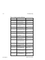
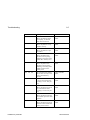
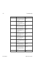
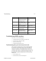


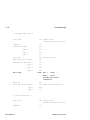

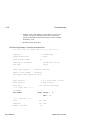
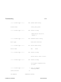
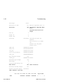


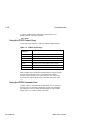
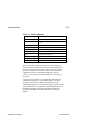


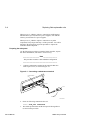

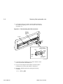
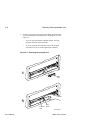
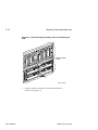
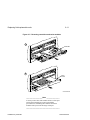
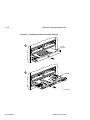


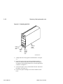

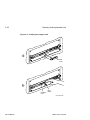


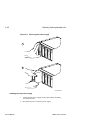
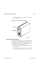

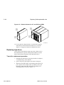

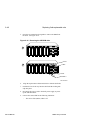

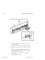
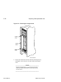
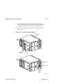
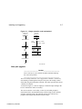
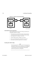

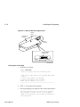

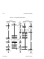
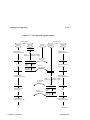


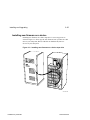


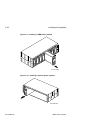
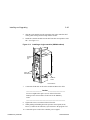


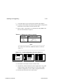
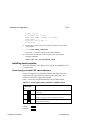
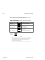

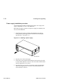
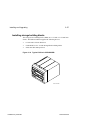
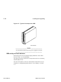
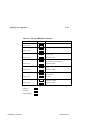


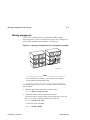
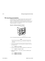

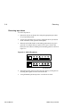
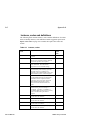
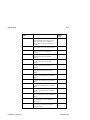

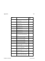

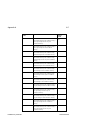

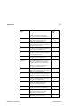
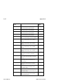
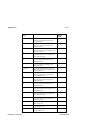


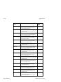
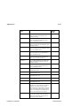

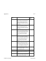
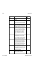
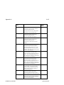
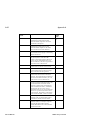
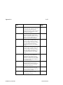
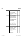
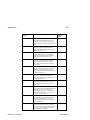
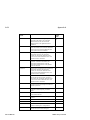
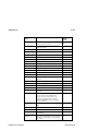
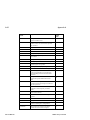
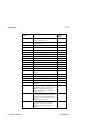
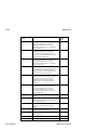
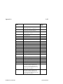
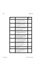

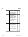
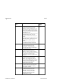
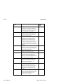

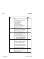
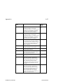
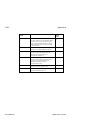
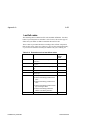

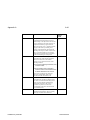
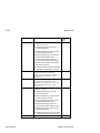
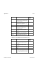
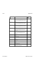
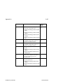
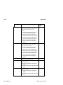

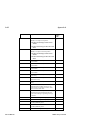
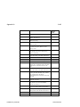
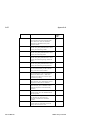
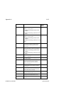
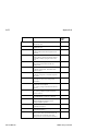
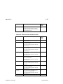
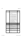
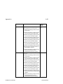

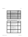
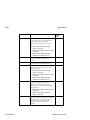
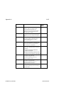
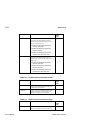
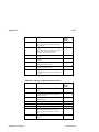
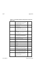

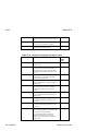
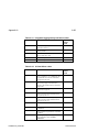
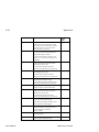

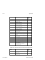
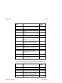

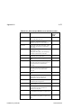
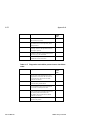
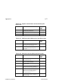

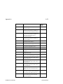
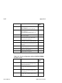
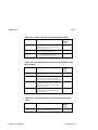
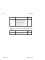
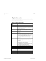

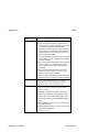


![PC755BM8 [Preliminary]](http://vs1.manualzilla.com/store/data/005786860_1-ac3ee01c2b00aeb18fc7f0a57a841c91-150x150.png)