1
StorageWorks™ Array Controllers
HS Family of Array Controllers
User’s Guide
Order Number: EK–HSFAM–UG. D01
The StorageWorks Array Controllers HS Family of Array Controllers
User’s Guide contains instructions for installing and using HSJ30,
HSJ40, HSD30, HSZ40–Ax, and HSZ40–Bx array controllers.
Digital Equipment Corporation
Maynard, Massachusetts
March 1995
The information in this document is subject to change without notice and should not be construed
as a commitment by Digital Equipment Corporation. Digital Equipment Corporation assumes no
responsibility for any errors that may appear in this document.
The software described in this document is furnished under a license and may be used or copied
only in accordance with the terms of such license.
No responsibility is assumed for the use or reliability of software on equipment that is not supplied
by Digital Equipment Corporation or its affiliated companies.
Restricted Rights: Use, duplication, or disclosure by the U.S. Government is subject to restrictions
as set forth in subparagraph (c) (1) (ii) of the Rights in Technical Data and Computer Software
clause at DFARS 252.227-7013.
© Digital Equipment Corporation 1995
Printed in U.S.A.
All Rights Reserved.
NOTE: This equipment generates, uses, and may emit radio frequency energy. The equipment has
been type tested and found to comply with the limits for a Class A digital device pursuant to Part
15 of the FCC rules. These limits are designed to provide reasonable protection against harmful
interference in a residential installation.
Any changes or modifications made to this equipment may void the user’s authority to operate the
equipment.
Operation of this equipment in a residential area may cause interference in which case the user
at his own expense will be required to take whatever measures will be required to take whatever
measures may be required to correct the interference.
Alpha, AlphaServer, CI, DEC, DECconnect, DECevent, DEC OSF/1, HSC, HSD30, HSJ, HSZ,
MSCP, OpenVMS, OpenVMS AXP, StorageWorks, TMSCP, VAX, VAXcluster, VAXsimPLUS, VMS,
VMScluster, and the DIGITAL logo are trademarks of Digital Equipment Corporation.
OSF and OSF/1 are registered trademarks of the Open Software Foundation, Inc.
All other trademarks and registered trademarks are the property of their respective holders.
This document was prepared using VAX DOCUMENT Version 2.1.
Contents
Preface . . . . . . . . . . . . . . . . . . . . . . . . . . . . . . . . . . . . . . . . . . . . . . . . . . . . . . . . . . . .
xv
1 Introduction to HS Array Controllers
1.1
1.2
1.3
1.3.1
1.3.2
1.3.3
1.4
1.5
1.5.1
1.5.2
1.5.3
1.6
1.7
1.8
1.9
1.10
1.10.1
1.10.2
1.11
1.12
1.13
Overview of HS Array Controllers . . . . . . . . . . . . . . . . . . . . . .
Housing for HS Array Controllers . . . . . . . . . . . . . . . . . . . . . .
Physical Description of HS Array Controllers . . . . . . . . . . . . .
HSJ30 and HSJ40 Array Controllers Physical Description
HSD30 Array Controller Physical Description . . . . . . . . . .
HSZ Array Controller Physical Description . . . . . . . . . . . .
Controller Host Interface Protocols . . . . . . . . . . . . . . . . . . . . .
Addressing Storage Within the Subsystem . . . . . . . . . . . . . . .
Controller Storage Addressing . . . . . . . . . . . . . . . . . . . . . .
Host Storage Addressing . . . . . . . . . . . . . . . . . . . . . . . . . .
Host Storage Addressing (HSZ Array Controllers) . . . . . . .
HSJ Array Controller Dual Data Link . . . . . . . . . . . . . . . . . . .
HS Array Controller Features . . . . . . . . . . . . . . . . . . . . . . . . .
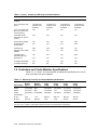
Controllers and Cache Modules Specifications . . . . . . . . . . . . .
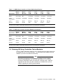
Ordering HS Array Controller Cache Modules . . . . . . . . . . . . .
StorageWorks Controller Subsystem Products . . . . . . . . . . . . .
Controller Shelf . . . . . . . . . . . . . . . . . . . . . . . . . . . . . . . . .
BA350–SB SBB Shelf . . . . . . . . . . . . . . . . . . . . . . . . . . . . .
MSCP and TMSCP Protocols (to Hosts) . . . . . . . . . . . . . . . . . .
SCSI Protocol (to Hosts) . . . . . . . . . . . . . . . . . . . . . . . . . . . . . .
SCSI Protocol (to Devices) . . . . . . . . . . . . . . . . . . . . . . . . . . . .
.
.
.
.
.
.
.
.
.
.
.
.
.
.
.
.
.
.
.
.
.
.
.
.
.
.
.
.
.
.
.
.
.
.
.
.
.
.
.
.
.
.
.
.
.
.
.
.
.
.
.
.
.
.
.
.
.
.
.
.
.
.
.
.
.
.
.
.
.
.
.
.
.
.
.
.
.
.
.
.
.
.
.
.
.
.
.
.
.
.
.
.
.
.
.
.
.
.
.
.
.
.
.
.
.
.
.
.
.
.
.
.
.
.
.
.
.
.
.
.
.
.
.
.
.
.
.
.
.
.
.
.
.
.
.
.
.
.
.
.
.
.
.
.
.
.
.
.
.
.
.
.
.
.
.
.
.
.
.
.
.
.
.
.
.
.
.
.
.
.
.
.
.
.
.
.
.
.
.
.
.
.
.
.
.
.
.
.
.
1–1
1–2
1–2
1–2
1–4
1–6
1–7
1–8
1–8
1–10
1–11
1–12
1–12
1–14
1–15
1–16
1–17
1–18
1–19
1–19
1–19
.
.
.
.
.
.
.
.
.
.
.
.
.
.
.
.
.
.
.
.
.
.
.
.
.
.
.
.
.
.
.
.
.
.
.
.
.
.
.
.
.
.
.
.
.
.
.
.
.
.
.
.
.
.
.
.
.
.
.
.
.
.
.
.
.
.
.
.
.
.
.
.
.
.
.
.
.
.
.
.
.
.
.
.
.
.
.
.
.
.
.
.
.
.
.
.
.
.
.
.
.
.
.
.
.
.
.
.
.
.
.
.
.
.
.
.
.
.
.
.
.
.
.
.
.
.
.
.
.
.
.
.
.
.
.
.
.
.
.
.
.
.
.
.
2–1
2–2
2–2
2–3
2–3
2–3
2–3
2–4
2–5
2–6
2–6
2–7
2–8
2–9
2–10
2–10
2 Controller Technical Description
2.1
HS Array Controller Hardware Functional Overview
2.1.1
Policy Processor Hardware . . . . . . . . . . . . . . . . . .
2.1.2
Bus Exchangers . . . . . . . . . . . . . . . . . . . . . . . . . .
2.1.3
CI, DSSI, or SCSI–2 Interfaces (Host Ports) . . . .
2.1.4
SCSI–2 Device Ports (Buses) . . . . . . . . . . . . . . . .
2.1.5
Read Cache Module . . . . . . . . . . . . . . . . . . . . . . .
2.1.6
Write-Back Cache Module . . . . . . . . . . . . . . . . . .
2.1.6.1
Battery Discharging . . . . . . . . . . . . . . . . . . . .
2.1.6.2
Battery Charging . . . . . . . . . . . . . . . . . . . . . .
2.1.7
Operator Control Panel . . . . . . . . . . . . . . . . . . . .
2.1.7.1
HSJ40 and HSJ30 Array Controller OCP . . .
2.1.7.2
HSD30 Array Controller OCP . . . . . . . . . . . .
2.1.7.3
HSZ Array Controller OCP . . . . . . . . . . . . . .
2.1.8
Program Card (PCMCIA) . . . . . . . . . . . . . . . . . . .
2.1.9
Nonvolatile Memory (NVMEM) . . . . . . . . . . . . . .
2.1.10
Maintenance Terminal Port . . . . . . . . . . . . . . . . .
.
.
.
.
.
.
.
.
.
.
.
.
.
.
.
.
.
.
.
.
.
.
.
.
.
.
.
.
.
.
.
.
.
.
.
.
.
.
.
.
.
.
.
.
.
.
.
.
.
.
.
.
.
.
.
.
.
.
.
.
.
.
.
.
.
.
.
.
.
.
.
.
.
.
.
.
.
.
.
.
.
.
.
.
.
.
.
.
.
.
.
.
.
.
.
.
.
.
.
.
.
.
.
.
.
.
.
.
.
.
.
.
iii
2.1.11
Dual Controller Port . . . . . . . . . . . . . . . . . . . . . . . . . . . . . . . . . . .
2.2
HS Array Controller Firmware Overview . . . . . . . . . . . . . . . . . . . . . .
2.2.1
Core Functions . . . . . . . . . . . . . . . . . . . . . . . . . . . . . . . . . . . . . . . .
2.2.1.1
Controller Self-Test and Diagnostics . . . . . . . . . . . . . . . . . . . .
2.2.1.2
Executive Functions . . . . . . . . . . . . . . . . . . . . . . . . . . . . . . . . .
2.2.2
Host Interconnect Functions . . . . . . . . . . . . . . . . . . . . . . . . . . . . .
2.2.3
Operator Interface and Subsystem Management Functions . . . . . .
2.2.3.1
Command Line Interpreter . . . . . . . . . . . . . . . . . . . . . . . . . . .
2.2.3.2
Diagnostic Utility Protocol . . . . . . . . . . . . . . . . . . . . . . . . . . . .
2.2.3.3
HSZ Array Controller Virtual Terminal Connection . . . . . . . . .
2.2.3.4
Local Programs . . . . . . . . . . . . . . . . . . . . . . . . . . . . . . . . . . . .
2.2.3.5
Error Logging and Fault Management . . . . . . . . . . . . . . . . . . .
2.2.4
Device Services . . . . . . . . . . . . . . . . . . . . . . . . . . . . . . . . . . . . . . .
2.2.5
Value-Added Functions . . . . . . . . . . . . . . . . . . . . . . . . . . . . . . . . .
2.3
What Is Failover? . . . . . . . . . . . . . . . . . . . . . . . . . . . . . . . . . . . . . . . . .
2.3.1
Setting Failover . . . . . . . . . . . . . . . . . . . . . . . . . . . . . . . . . . . . . . .
2.3.2
Exiting Failover . . . . . . . . . . . . . . . . . . . . . . . . . . . . . . . . . . . . . . .
2.3.3
Taking Controllers Out of Failover . . . . . . . . . . . . . . . . . . . . . . . . .
2.3.4
Using Failover Commands When Write-Back Cache Is in Use . . . .
2.3.5
Resolving a Configuration Mismatch after a Hardware Mismatch .
2.4
HSZ Array Controller Failover Operation . . . . . . . . . . . . . . . . . . . . . .
2.4.1
Transparent Controller Failover Resulting from a Fault . . . . . . . .
2.4.2
Transparent Controller Failover Resulting from Operator Action .
.
.
.
.
.
.
.
.
.
.
.
.
.
.
.
.
.
.
.
.
.
.
.
.
.
.
.
.
.
.
.
.
.
.
.
.
.
.
.
.
.
.
.
.
.
.
.
.
.
.
.
.
.
.
.
.
.
.
.
.
.
.
.
.
.
.
.
.
.
2–12
2–12
2–13
2–13
2–13
2–13
2–14
2–14
2–14
2–14
2–14
2–15
2–15
2–15
2–16
2–17
2–18
2–18
2–19
2–19
2–20
2–20
2–22
.
.
.
.
.
.
.
.
.
.
.
.
.
.
.
.
.
.
.
.
.
.
.
.
.
.
.
.
.
.
.
.
.
.
.
.
.
.
.
.
.
.
.
.
.
.
.
.
.
.
.
.
.
.
.
.
.
.
.
.
.
.
.
.
.
.
.
.
.
.
.
.
.
.
.
.
.
.
.
.
.
3–1
3–1
3–2
3–6
3–8
3–9
3–10
3–11
3–12
3–13
3–13
3–14
3–15
3–17
3–17
3–17
3–19
3–20
3–21
3–21
3–22
3–24
3–25
3–25
3–25
3–25
3–26
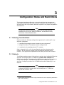
3 Configuration Rules and Restrictions
3.1
3.2
3.2.1
3.2.2
3.2.3
3.2.4
3.2.4.1
3.2.4.2
3.3
3.3.1
3.3.2
3.3.3
3.3.4
3.4
3.4.1
3.4.2
3.4.3
3.4.4
3.4.5
3.4.6
3.4.7
3.5
3.6
3.7
3.7.1
3.7.2
3.7.3
iv
Ordering Considerations . . . . . . . . . . . . . . . . . . . . . . . . .
Cabinets . . . . . . . . . . . . . . . . . . . . . . . . . . . . . . . . . . . . . .
SW800-Series Data Center Cabinet . . . . . . . . . . . . . .
SW500-Series Cabinets . . . . . . . . . . . . . . . . . . . . . . .
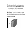
SW300-Series Deskside RAID Enclosure . . . . . . . . . .
Shelves . . . . . . . . . . . . . . . . . . . . . . . . . . . . . . . . . . . .
BA350-Series . . . . . . . . . . . . . . . . . . . . . . . . . . . .
SW300-Series Cabinet Shelf . . . . . . . . . . . . . . . . .
Controllers . . . . . . . . . . . . . . . . . . . . . . . . . . . . . . . . . . . .
Nonredundant HS Array Controller Configurations . .
Dual-Redundant HS Array Controller Configurations
Optimal Performance Configurations . . . . . . . . . . . . .
Optimal Availability Configurations . . . . . . . . . . . . . .
Typical and Recommended Configurations . . . . . . . . . . . .
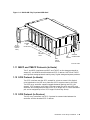
3½-Inch SBB Restrictions . . . . . . . . . . . . . . . . . . . . .
3½-Inch SBB Recommended Configurations . . . . . . .
5¼-Inch SBB Restrictions . . . . . . . . . . . . . . . . . . . . .
5¼-Inch SBB Recommended Configurations . . . . . . .
Intermixing 5¼-Inch and 3½-Inch SBBs . . . . . . . . . .
Atypical Configurations . . . . . . . . . . . . . . . . . . . . . . .
SW300-Series Cabinet Deskside RAID Configuration
Host Port Cable Lengths . . . . . . . . . . . . . . . . . . . . . . . . .
CD–ROM Restrictions . . . . . . . . . . . . . . . . . . . . . . . . . . .
Host Adapter Support . . . . . . . . . . . . . . . . . . . . . . . . . . .
HSJ Array Controllers Host Adapter Support . . . . . .
HSD30 Array Controller Host Adapter Support . . . . .
HSZ Array Controller Host Adapter Support . . . . . . .
.
.
.
.
.
.
.
.
.
.
.
.
.
.
.
.
.
.
.
.
.
.
.
.
.
.
.
.
.
.
.
.
.
.
.
.
.
.
.
.
.
.
.
.
.
.
.
.
.
.
.
.
.
.
.
.
.
.
.
.
.
.
.
.
.
.
.
.
.
.
.
.
.
.
.
.
.
.
.
.
.
.
.
.
.
.
.
.
.
.
.
.
.
.
.
.
.
.
.
.
.
.
.
.
.
.
.
.
.
.
.
.
.
.
.
.
.
.
.
.
.
.
.
.
.
.
.
.
.
.
.
.
.
.
.
.
.
.
.
.
.
.
.
.
.
.
.
.
.
.
.
.
.
.
.
.
.
.
.
.
.
.
.
.
.
.
.
.
.
.
.
.
.
.
.
.
.
.
.
.
.
.
.
.
.
.
.
.
.
.
.
.
.
.
.
.
.
.
.
.
.
.
.
.
.
.
.
.
.
.
.
.
.
.
.
.
.
.
.
.
.
.
.
.
.
.
.
.
.
.
.
.
.
.
.
.
.
.
.
.
.
.
.
.
.
.
.
.
.
.
.
.
.
.
.
.
.
.
.
.
.
.
.
.
.
.
.
.
.
.
4 Installation
4.1
Customer Site Preparation . . . . . . . . . . . . . . . . . . . . . . . . . . . . . . . . . . . . .
4.1.1
Power and Power Cord Requirements . . . . . . . . . . . . . . . . . . . . . . . . .
4.1.2
Shelf Power Configuration Rules . . . . . . . . . . . . . . . . . . . . . . . . . . . . .
4.1.3
Environmental Considerations . . . . . . . . . . . . . . . . . . . . . . . . . . . . . . .
4.2
Before You Begin . . . . . . . . . . . . . . . . . . . . . . . . . . . . . . . . . . . . . . . . . . . .
4.2.1
Personnel Needed for Installation . . . . . . . . . . . . . . . . . . . . . . . . . . . .
4.2.2
Tools Needed for Installation . . . . . . . . . . . . . . . . . . . . . . . . . . . . . . . .
4.2.3
Electrostatic Discharge Protection Guidelines . . . . . . . . . . . . . . . . . . .
4.3
Controller Components Handling Guidelines . . . . . . . . . . . . . . . . . . . . . . .
4.3.1
Module Handling Guidelines . . . . . . . . . . . . . . . . . . . . . . . . . . . . . . . .
4.3.2
Program Card Handling Guidelines . . . . . . . . . . . . . . . . . . . . . . . . . . .
4.3.3
Cabling Guidelines . . . . . . . . . . . . . . . . . . . . . . . . . . . . . . . . . . . . . . . .
4.3.3.1
CI Host Port Cable Handling Guidelines for HSJ Array
Controllers . . . . . . . . . . . . . . . . . . . . . . . . . . . . . . . . . . . . . . . . . . .
4.3.3.2
DSSI Host Port Cable Handling Guidelines for HSD30 Array
Controllers . . . . . . . . . . . . . . . . . . . . . . . . . . . . . . . . . . . . . . . . . . .
4.3.3.3
SCSI Host Port Cable Handling Guidelines for HSZ Array
Controllers . . . . . . . . . . . . . . . . . . . . . . . . . . . . . . . . . . . . . . . . . . .
4.3.3.4
Controller-to-Storage Shelf SCSI–2 Device Cable Guidelines . . . . .
4.4
Unpacking Your Subsystem . . . . . . . . . . . . . . . . . . . . . . . . . . . . . . . . . . . .
4.5
Installing a Preconfigured or CTO Controller Subsystem . . . . . . . . . . . . .
4.6
Installation Instructions for Preconfigured and CTO Subsystems . . . . . . .
4.6.1
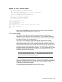
Connecting a Terminal to the Maintenance Terminal Port . . . . . . . . . .
4.6.2
Preset Controller Configuration Parameters . . . . . . . . . . . . . . . . . . . .
4.6.2.1
Installing Host Port Cables for HSJ Array Controllers . . . . . . . . .
4.6.2.2
Installing Host Port Cables, Trilinks, and Terminators for HSD30
Array Controllers . . . . . . . . . . . . . . . . . . . . . . . . . . . . . . . . . . . . . .
4.6.2.3
Installing Host Port Cables, Trilinks, and Terminators for HSZ
Array Controllers . . . . . . . . . . . . . . . . . . . . . . . . . . . . . . . . . . . . . .
4.7
Creating a Dual-Redundant HS Array Controller Configuration . . . . . . . .
4.8
Installing the Program Card . . . . . . . . . . . . . . . . . . . . . . . . . . . . . . . . . . .
4.9
Upgrading Your HS Array Controller Subsystem Components . . . . . . . . .
4.10
Upgrading Your Cache Module . . . . . . . . . . . . . . . . . . . . . . . . . . . . . . . . . .
4–1
4–2
4–2
4–2
4–3
4–3
4–3
4–4
4–4
4–5
4–5
4–6
4–7
4–7
4–9
4–9
4–10
4–10
4–14
4–19
4–20
4–21
4–22
4–23
4–24
4–27
4–30
4–30
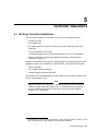
5 Controller Operations
5.1
5.1.1
5.1.2
5.1.3
5.2
5.2.1
5.2.2
5.2.3
5.2.4
5.2.5
5.3
5.4
5.5
5.5.1
5.5.2
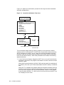
HS Array Controller Initialization . . . . . . . . . . . . . . . . . . . . . . . . . . . . .
Dual-Redundant Controller Configuration Initialization Sequence .
Controller Subsystem Initialization . . . . . . . . . . . . . . . . . . . . . . . . .
Controller Cache Module Initialization Sequence . . . . . . . . . . . . . . .
Command Line Interpreter . . . . . . . . . . . . . . . . . . . . . . . . . . . . . . . . . .
CLI Access . . . . . . . . . . . . . . . . . . . . . . . . . . . . . . . . . . . . . . . . . . . .
CLI Command Sets . . . . . . . . . . . . . . . . . . . . . . . . . . . . . . . . . . . . .
How to Exit CLI . . . . . . . . . . . . . . . . . . . . . . . . . . . . . . . . . . . . . . . .
Setting Configuration Parameters for a Nonredundant Controller
Configuration . . . . . . . . . . . . . . . . . . . . . . . . . . . . . . . . . . . . . . . . . .
Setting Configuration Parameters for a Dual-Redundant Controller
Configuration . . . . . . . . . . . . . . . . . . . . . . . . . . . . . . . . . . . . . . . . . .
Using the TRANSPORTABLE and NOTRANSPORTABLE Qualifiers . .
Customer Acceptance Tests with Power Applied . . . . . . . . . . . . . . . . . .
How to Use and Interpret the Controller OCP Buttons and LEDs . . . . .
Uses of the OCP Buttons and LEDs . . . . . . . . . . . . . . . . . . . . . . . . .
How the OCP Functions . . . . . . . . . . . . . . . . . . . . . . . . . . . . . . . . . .
.
.
.
.
.
.
.
.
.
.
.
.
.
.
.
.
5–1
5–3
5–3
5–4
5–4
5–4
5–5
5–6
..
5–6
.
.
.
.
.
.
.
.
.
.
.
.
5–11
5–17
5–17
5–18
5–18
5–18
v
5.6
Power Supply Status LEDs . . . . . . . . . . . . . . . . . . . . . . . . . . . . . . . . . . . .
5.7
Battery Backup Unit (BBU) Status LEDs . . . . . . . . . . . . . . . . . . . . . . . . .
5.8
Environmental Monitor Unit (EMU) for HSZ40–Bx Array Controllers . . .
5.8.1
EMU Fault Detection . . . . . . . . . . . . . . . . . . . . . . . . . . . . . . . . . . . . . .
5.8.2
Controller Fault Detection . . . . . . . . . . . . . . . . . . . . . . . . . . . . . . . . . .
5.9
Description of Device Warm Swap . . . . . . . . . . . . . . . . . . . . . . . . . . . . . . .
5.9.1
Device Warm Swap . . . . . . . . . . . . . . . . . . . . . . . . . . . . . . . . . . . . . . .
5.9.1.1
Disk SBB Warm Swap Removal . . . . . . . . . . . . . . . . . . . . . . . . . . .
5.9.1.2
Disk SBB Warm Swap Replacement . . . . . . . . . . . . . . . . . . . . . . .
5.9.2
Tape Drive Warm Swap (Removal/Replacement) . . . . . . . . . . . . . . . . .
5.10
When the Quiesce Bus State Is Not Displayed . . . . . . . . . . . . . . . . . . . . . .
5.11
Controller Warm Swap Utility (C_SWAP) . . . . . . . . . . . . . . . . . . . . . . . . .
5.11.1
When to Use C_SWAP . . . . . . . . . . . . . . . . . . . . . . . . . . . . . . . . . . . . .
5.11.2
Functions of C_SWAP . . . . . . . . . . . . . . . . . . . . . . . . . . . . . . . . . . . . .
5.11.2.1
Removing a Controller and/or Cache Module During a C_SWAP
Operation . . . . . . . . . . . . . . . . . . . . . . . . . . . . . . . . . . . . . . . . . . . .
5.11.2.2
Replacing a Controller and/or Cache Module During a C_SWAP
Operation . . . . . . . . . . . . . . . . . . . . . . . . . . . . . . . . . . . . . . . . . . . .
5.12
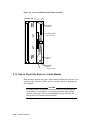
How to Physically Remove a Controller Module . . . . . . . . . . . . . . . . . . . . .
5.13
How to Physically Remove a Cache Module . . . . . . . . . . . . . . . . . . . . . . . .
5.14
How to Physically Replace a Controller Module . . . . . . . . . . . . . . . . . . . . .
5.15
How to Physically Replace a Cache Module . . . . . . . . . . . . . . . . . . . . . . . .
5.16
Checking the Status of the Write-Back Cache Module Batteries . . . . . . . .
5.17
Using the Controller SHUTDOWN Command Prior to Turning Off
Controller Power . . . . . . . . . . . . . . . . . . . . . . . . . . . . . . . . . . . . . . . . . . . .
5.18
Using DISMOUNT or SHUTDOWN Before Moving Devices . . . . . . . . . . .
5–24
5–24
5–24
5–24
5–25
5–27
5–27
5–27
5–29
5–30
5–30
5–30
5–31
5–32
5–32
5–34
5–35
5–38
5–39
5–43
5–43
5–43
5–45
6 Working with RAID Arrays
6.1
6.1.1
6.1.2
6.1.3
6.1.4
6.1.5
6.2
6.3
6.4
6.4.1
6.5
6.5.1
6.5.2
6.5.3
6.5.4
6.5.5
6.5.6
6.5.7
6.6
6.6.1
6.6.2
6.7
6.8
6.9
6.10
vi
HS Array Controller Family RAID Overview . . . . . . . . . .
RAID Level 0 . . . . . . . . . . . . . . . . . . . . . . . . . . . . . . .
RAID 0 & 1 . . . . . . . . . . . . . . . . . . . . . . . . . . . . . . . .
RAID Level 1 . . . . . . . . . . . . . . . . . . . . . . . . . . . . . . .
RAID Level 3 . . . . . . . . . . . . . . . . . . . . . . . . . . . . . . .
RAID Level 5 . . . . . . . . . . . . . . . . . . . . . . . . . . . . . . .
RAID Array Terminology . . . . . . . . . . . . . . . . . . . . . . . . .
RAIDset and Mirrorset Rules and Important Information
Avoiding Unwanted Unwritten Cached Data Conditions .
Using CLI Commands with Write-Back Cache . . . . . .
Planning Your RAIDsets . . . . . . . . . . . . . . . . . . . . . . . . .
Creating a RAIDset . . . . . . . . . . . . . . . . . . . . . . . . . .
Storageset SHOW Commands . . . . . . . . . . . . . . . . . .
Adding and Deleting Spareset Members . . . . . . . . . .
Showing and Deleting Failedset Members . . . . . . . . .
Changing RAIDset Characteristics . . . . . . . . . . . . . .
Deleting a RAIDset . . . . . . . . . . . . . . . . . . . . . . . . . .
Moving a RAIDset . . . . . . . . . . . . . . . . . . . . . . . . . . .
Adding a Stripeset (RAID Level 0) . . . . . . . . . . . . . . . . . .
Moving a Stripeset or Stripeset Member . . . . . . . . . .
Showing Stripesets . . . . . . . . . . . . . . . . . . . . . . . . . . .
Planning Your Mirrorsets . . . . . . . . . . . . . . . . . . . . . . . . .
Using Mirrorsets to Obtain Snapshot Copies of Data . . . .
Mirrorset Considerations for Snapshot Copies . . . . . . . . .
Steps for Creating a Mirrorset . . . . . . . . . . . . . . . . . . . . .
.
.
.
.
.
.
.
.
.
.
.
.
.
.
.
.
.
.
.
.
.
.
.
.
.
.
.
.
.
.
.
.
.
.
.
.
.
.
.
.
.
.
.
.
.
.
.
.
.
.
.
.
.
.
.
.
.
.
.
.
.
.
.
.
.
.
.
.
.
.
.
.
.
.
.
.
.
.
.
.
.
.
.
.
.
.
.
.
.
.
.
.
.
.
.
.
.
.
.
.
.
.
.
.
.
.
.
.
.
.
.
.
.
.
.
.
.
.
.
.
.
.
.
.
.
.
.
.
.
.
.
.
.
.
.
.
.
.
.
.
.
.
.
.
.
.
.
.
.
.
.
.
.
.
.
.
.
.
.
.
.
.
.
.
.
.
.
.
.
.
.
.
.
.
.
.
.
.
.
.
.
.
.
.
.
.
.
.
.
.
.
.
.
.
.
.
.
.
.
.
.
.
.
.
.
.
.
.
.
.
.
.
.
.
.
.
.
.
.
.
.
.
.
.
.
.
.
.
.
.
.
.
.
.
.
.
.
.
.
.
.
.
.
.
.
.
.
.
.
.
.
.
.
.
.
.
.
.
.
.
.
.
.
.
.
.
.
.
.
.
.
.
.
.
.
.
.
.
.
.
.
.
.
.
.
.
.
.
.
.
.
.
.
.
.
.
.
.
.
.
.
.
.
.
.
.
.
.
.
.
.
.
.
.
.
.
.
.
.
.
.
.
.
.
.
6–1
6–2
6–2
6–2
6–3
6–4
6–4
6–7
6–8
6–9
6–9
6–10
6–11
6–13
6–14
6–14
6–15
6–16
6–17
6–17
6–17
6–18
6–18
6–19
6–20
6.10.1
Configuring Host Units into Mirrorsets . . . . . . . . . . . . .
6.11
Mirrorset Command Overview . . . . . . . . . . . . . . . . . . . . . . .
6.11.1
Creating a Mirrorset . . . . . . . . . . . . . . . . . . . . . . . . . . .
6.11.2
Mirrorset SET Commands and Qualifiers . . . . . . . . . . .
6.11.3
Mirrorset SHOW Commands . . . . . . . . . . . . . . . . . . . . .
6.11.4
REDUCE disk-device-name1 Command . . . . . . . . . . . . .
6.11.5
MIRROR disk-device-name container-name Command . .
6.11.6
UNMIRROR disk_device-name . . . . . . . . . . . . . . . . . . .
6.12
RAIDset and Mirrorset Availability, Performance, and Cost
.
.
.
.
.
.
.
.
.
.
.
.
.
.
.
.
.
.
.
.
.
.
.
.
.
.
.
.
.
.
.
.
.
.
.
.
.
.
.
.
.
.
.
.
.
.
.
.
.
.
.
.
.
.
.
.
.
.
.
.
.
.
.
.
.
.
.
.
.
.
.
.
.
.
.
.
.
.
.
.
.
.
.
.
.
.
.
.
.
.
.
.
.
.
.
.
.
.
.
6–21
6–22
6–22
6–23
6–24
6–24
6–25
6–25
6–25
7.1
Initialization Diagnostics . . . . . . . . . . . . . . . . . . . . . . . . . . . . . . . . . . . . . .
7.2
Connecting to the Controller . . . . . . . . . . . . . . . . . . . . . . . . . . . . . . . . . . .
7.3
HS Array Controller Local Programs . . . . . . . . . . . . . . . . . . . . . . . . . . . . .
7.3.1
DILX . . . . . . . . . . . . . . . . . . . . . . . . . . . . . . . . . . . . . . . . . . . . . . . . . .
7.3.1.1
Invoking DILX . . . . . . . . . . . . . . . . . . . . . . . . . . . . . . . . . . . . . . . .
7.3.1.2
Interrupting DILX Execution . . . . . . . . . . . . . . . . . . . . . . . . . . . . .
7.3.1.3
Running DILX . . . . . . . . . . . . . . . . . . . . . . . . . . . . . . . . . . . . . . . .
7.3.2
DILX Examples . . . . . . . . . . . . . . . . . . . . . . . . . . . . . . . . . . . . . . . . . .
7.3.2.1
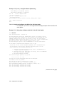
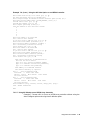
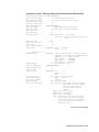
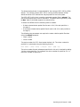
Using All Functions (Long Run) . . . . . . . . . . . . . . . . . . . . . . . . . . .
7.3.2.2
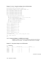
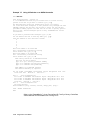
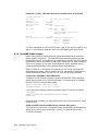
Using All Defaults (Read-Only) . . . . . . . . . . . . . . . . . . . . . . . . . . .
7.3.2.3
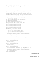
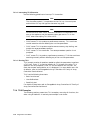
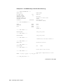
Using Auto-Configure with Half of the All Units Option . . . . . . . .
7.3.2.4
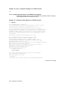
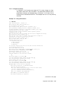
Using Auto-Configure with the All Units Option . . . . . . . . . . . . . .
7.3.2.5
Using Auto-Configure on an HSZ40 Array Controller . . . . . . . . . .
7.3.2.6
Using the All Units Option on an HSZ40 Array Controller . . . . . .
7.3.2.7
Using All Defaults on an HSZ40 Array Controller . . . . . . . . . . . . .
7.3.3
TILX . . . . . . . . . . . . . . . . . . . . . . . . . . . . . . . . . . . . . . . . . . . . . . . . . .
7.3.3.1
Invoking TILX . . . . . . . . . . . . . . . . . . . . . . . . . . . . . . . . . . . . . . . .
7.3.3.2
Interrupting TILX Execution . . . . . . . . . . . . . . . . . . . . . . . . . . . . .
7.3.3.3
Running TILX . . . . . . . . . . . . . . . . . . . . . . . . . . . . . . . . . . . . . . . .
7.3.4
TILX Examples . . . . . . . . . . . . . . . . . . . . . . . . . . . . . . . . . . . . . . . . . .
7.3.4.1
Using All Functions . . . . . . . . . . . . . . . . . . . . . . . . . . . . . . . . . . . .
7.3.4.2
Using All Defaults . . . . . . . . . . . . . . . . . . . . . . . . . . . . . . . . . . . . .
7.3.5
VTDPY Utility . . . . . . . . . . . . . . . . . . . . . . . . . . . . . . . . . . . . . . . . . . .
7.3.5.1
How to Run VTDPY . . . . . . . . . . . . . . . . . . . . . . . . . . . . . . . . . . . .
7.3.5.2
Using the VTDPY Control Keys . . . . . . . . . . . . . . . . . . . . . . . . . . .
7.3.5.3
Using the VTDPY Command Line . . . . . . . . . . . . . . . . . . . . . . . .
7.3.5.4
How to Interpret the VTDPY Display Fields . . . . . . . . . . . . . . . . .
7.3.6
Firmware Licensing System (FLS) . . . . . . . . . . . . . . . . . . . . . . . . . . . .
7.3.6.1
Enabling Options . . . . . . . . . . . . . . . . . . . . . . . . . . . . . . . . . . . . . .
7.3.6.2
Disabling Options . . . . . . . . . . . . . . . . . . . . . . . . . . . . . . . . . . . . .
7.3.6.3
License Key . . . . . . . . . . . . . . . . . . . . . . . . . . . . . . . . . . . . . . . . . .
7.3.6.4
Using the Menu . . . . . . . . . . . . . . . . . . . . . . . . . . . . . . . . . . . . . . .
7.3.6.5
Example . . . . . . . . . . . . . . . . . . . . . . . . . . . . . . . . . . . . . . . . . . . . .
7.3.6.6
Messages . . . . . . . . . . . . . . . . . . . . . . . . . . . . . . . . . . . . . . . . . . . .
7.3.7
Configure (CONFIG) Utility . . . . . . . . . . . . . . . . . . . . . . . . . . . . . . . . .
7.3.7.1
When to Use the Configure Utility . . . . . . . . . . . . . . . . . . . . . . . . .
7.3.7.2
Description . . . . . . . . . . . . . . . . . . . . . . . . . . . . . . . . . . . . . . . . . . .
7.3.7.3
Running the Configure Utility . . . . . . . . . . . . . . . . . . . . . . . . . . . .
7.3.8
HSZterm Utility . . . . . . . . . . . . . . . . . . . . . . . . . . . . . . . . . . . . . . . . . .
7.3.9
Fault Manager Utility (FMU) . . . . . . . . . . . . . . . . . . . . . . . . . . . . . . .
7–1
7–2
7–2
7–2
7–3
7–4
7–4
7–6
7–6
7–9
7–10
7–11
7–12
7–14
7–15
7–17
7–17
7–18
7–18
7–18
7–19
7–20
7–21
7–22
7–22
7–22
7–23
7–54
7–54
7–54
7–54
7–54
7–55
7–57
7–57
7–57
7–57
7–57
7–59
7–59
7 Diagnostics and Utilities
vii
.
.
.
.
.
.
.
.
.
.
.
.
.
.
.
.
.
.
.
.
.
.
.
.
.
.
.
.
.
.
7–59
7–60
7–60
7–60
7–62
7–62
7–63
7–64
7–65
7–66
7–67
7–68
7–68
7–71
7–71
7–71
7–72
7–72
7–74
7–75
7–75
7–85
7–101
7–101
7–101
7–101
7–102
7–103
7–103
7–103
8.1
Digital Supported Operating Systems . . . . . . . . . . . . . . . . . . . . . . . . . . . .
8.2
HS Array Controller System Management . . . . . . . . . . . . . . . . . . . . . . . . .
8.3
OpenVMS and VMS VAX Operating Systems . . . . . . . . . . . . . . . . . . . . . .
8.3.1
CLI Access via DUP with OpenVMS Operating System . . . . . . . . . . . .
8.3.2
OpenVMS VAX Support . . . . . . . . . . . . . . . . . . . . . . . . . . . . . . . . . . . .
8.3.2.1
HSJ and HSD30 Array Controller Disks as Initialization
Devices . . . . . . . . . . . . . . . . . . . . . . . . . . . . . . . . . . . . . . . . . . . . . .
8.3.2.2
HSJ and HSD30 Array Controller-Attached Disk Drives and VMS
AUTOGEN Program . . . . . . . . . . . . . . . . . . . . . . . . . . . . . . . . . . .
8.3.3
Using the OpenVMS Preferred Path Utility . . . . . . . . . . . . . . . . . . . . .
8.3.4
SHOW DEVICE Command with OpenVMS . . . . . . . . . . . . . . . . . . . . .
8.3.5
Using the CLUSTER_SIZE Qualifier for Large Devices or Storagesets
with OpenVMS Systems . . . . . . . . . . . . . . . . . . . . . . . . . . . . . . . . . . . .
8.3.5.1
VAX VMS Version 5.5–1 (and earlier) . . . . . . . . . . . . . . . . . . . . . .
8.3.5.2
OpenVMS VAX V5.5–2 (and above) . . . . . . . . . . . . . . . . . . . . . . . .
8.3.6
Shadow Set Operation with OpenVMS Systems . . . . . . . . . . . . . . . . .
8.3.7
ERF with OpenVMS Systems . . . . . . . . . . . . . . . . . . . . . . . . . . . . . . .
8.3.8
DECevent for OpenVMS VAX and OpenVMS Alpha Operating
Systems . . . . . . . . . . . . . . . . . . . . . . . . . . . . . . . . . . . . . . . . . . . . . . . .
8.3.9
OpenVMS Alpha Support . . . . . . . . . . . . . . . . . . . . . . . . . . . . . . . . . . .
8.4
DEC OSF/1 Support . . . . . . . . . . . . . . . . . . . . . . . . . . . . . . . . . . . . . . . . . .
8–1
8–2
8–2
8–2
8–3
7.3.10
7.3.10.1
7.3.10.2
7.3.10.3
7.3.10.4
7.3.10.5
7.3.10.6
7.3.10.7
7.3.10.8
7.3.10.9
7.3.10.10
7.3.10.11
7.3.10.12
7.3.10.13
7.3.11
7.3.11.1
7.3.11.2
7.3.11.3
7.3.11.4
7.3.11.5
7.3.11.6
7.3.12
7.3.13
7.3.13.1
7.3.13.2
7.3.13.3
7.3.13.4
7.3.13.5
7.3.13.6
7.3.13.7
Configuration Menu (CFMENU) . . . . . . . . . . . . . . . . . . . . . . .
Restrictions . . . . . . . . . . . . . . . . . . . . . . . . . . . . . . . . . . . .
Main Menu . . . . . . . . . . . . . . . . . . . . . . . . . . . . . . . . . . . .
Adding Devices . . . . . . . . . . . . . . . . . . . . . . . . . . . . . . . . .
Adding Mirrorsets . . . . . . . . . . . . . . . . . . . . . . . . . . . . . . .
Adding Stripesets . . . . . . . . . . . . . . . . . . . . . . . . . . . . . . . .
Adding RAIDsets . . . . . . . . . . . . . . . . . . . . . . . . . . . . . . . .
Adding to Sparesets . . . . . . . . . . . . . . . . . . . . . . . . . . . . . .
Adding Passthroughs (HSJ and HSD30 array controllers) .
Initializing Containers . . . . . . . . . . . . . . . . . . . . . . . . . . . .
Adding Units . . . . . . . . . . . . . . . . . . . . . . . . . . . . . . . . . . .
Terminal Setup . . . . . . . . . . . . . . . . . . . . . . . . . . . . . . . . .
Messages . . . . . . . . . . . . . . . . . . . . . . . . . . . . . . . . . . . . . .
Exiting CFMENU . . . . . . . . . . . . . . . . . . . . . . . . . . . . . . .
Code Load/Code Patch (CLCP) Utility . . . . . . . . . . . . . . . . . . .
Invoking the CLCP Utility . . . . . . . . . . . . . . . . . . . . . . . . .
Code Loading . . . . . . . . . . . . . . . . . . . . . . . . . . . . . . . . . . .
Using Code Load . . . . . . . . . . . . . . . . . . . . . . . . . . . . . . . .
Code Patching . . . . . . . . . . . . . . . . . . . . . . . . . . . . . . . . . .
Special Code Patch Considerations . . . . . . . . . . . . . . . . . .
Exit Option . . . . . . . . . . . . . . . . . . . . . . . . . . . . . . . . . . . .
CLONE Utility . . . . . . . . . . . . . . . . . . . . . . . . . . . . . . . . . . . . .
Command Disks (HSJ and HSD30 Array Controllers) . . . . . . .
Uses for Command Disks . . . . . . . . . . . . . . . . . . . . . . . . . .
Creating a Command Disk . . . . . . . . . . . . . . . . . . . . . . . . .
Controller Setup . . . . . . . . . . . . . . . . . . . . . . . . . . . . . . . . .
Host Setup . . . . . . . . . . . . . . . . . . . . . . . . . . . . . . . . . . . . .
Communicating with a Command Disk . . . . . . . . . . . . . . .
Performance . . . . . . . . . . . . . . . . . . . . . . . . . . . . . . . . . . . .
Maintenance . . . . . . . . . . . . . . . . . . . . . . . . . . . . . . . . . . .
.
.
.
.
.
.
.
.
.
.
.
.
.
.
.
.
.
.
.
.
.
.
.
.
.
.
.
.
.
.
.
.
.
.
.
.
.
.
.
.
.
.
.
.
.
.
.
.
.
.
.
.
.
.
.
.
.
.
.
.
.
.
.
.
.
.
.
.
.
.
.
.
.
.
.
.
.
.
.
.
.
.
.
.
.
.
.
.
.
.
.
.
.
.
.
.
.
.
.
.
.
.
.
.
.
.
.
.
.
.
.
.
.
.
.
.
.
.
.
.
.
.
.
.
.
.
.
.
.
.
.
.
.
.
.
.
.
.
.
.
.
.
.
.
.
.
.
.
.
.
8 Operating System Support
viii
8–4
8–5
8–6
8–6
8–7
8–7
8–8
8–8
8–9
8–13
8–16
8–17
8.4.1
uerf with DEC OSF/1 for HSZ Array Controllers . . . . . . . . . . . . . . . . .
8.4.2
DECsafe Available Server Environment (ASE) . . . . . . . . . . . . . . . . . .
8.4.3
Configurations and Device Support for the HSZ Array Controllers . . .
8.4.3.1
Virtual Terminal Capability . . . . . . . . . . . . . . . . . . . . . . . . . . . . . .
8.4.3.2
DEC OSF/1 Device Special Files for HSZ Array Controllers . . . . .
8.5
Basic Steps for Configuring an HSZ Array Controller Under the DEC
OSF/1 Operating System . . . . . . . . . . . . . . . . . . . . . . . . . . . . . . . . . . . . . .
8.6
Terminology . . . . . . . . . . . . . . . . . . . . . . . . . . . . . . . . . . . . . . . . . . . . . . . .
8.7
Specific Procedures . . . . . . . . . . . . . . . . . . . . . . . . . . . . . . . . . . . . . . . . . . .
8.8
Configuring Units on the HSZ40 Array Controller . . . . . . . . . . . . . . . . . . .
8.9
TRANSPORTABLE versus NOTRANSPORTABLE . . . . . . . . . . . . . . . . . .
8.10
Multiple Device Containers . . . . . . . . . . . . . . . . . . . . . . . . . . . . . . . . . . . .
8.11
Initialization of Controllers . . . . . . . . . . . . . . . . . . . . . . . . . . . . . . . . . . . .
8.12
Creation of Units . . . . . . . . . . . . . . . . . . . . . . . . . . . . . . . . . . . . . . . . . . . .
8.13
DEC OSF/1 Special Files . . . . . . . . . . . . . . . . . . . . . . . . . . . . . . . . . . . . . .
8.13.1
Creating a Device Special File . . . . . . . . . . . . . . . . . . . . . . . . . . . . . . .
8.14
MAKEDEV Utility . . . . . . . . . . . . . . . . . . . . . . . . . . . . . . . . . . . . . . . . . . .
8.15
Helpful Utilities . . . . . . . . . . . . . . . . . . . . . . . . . . . . . . . . . . . . . . . . . . . . .
8.16
SCU Utility . . . . . . . . . . . . . . . . . . . . . . . . . . . . . . . . . . . . . . . . . . . . . . . .
8.17
Configuration File Entries for HSZ40 Units . . . . . . . . . . . . . . . . . . . . . . . .
8.18
Using iostat and Other Utilities . . . . . . . . . . . . . . . . . . . . . . . . . . . . . . . . .
8.19
Using genvmunix . . . . . . . . . . . . . . . . . . . . . . . . . . . . . . . . . . . . . . . . . . . .
8–17
8–21
8–22
8–22
8–22
8–25
8–26
8–28
8–30
8–32
8–32
8–33
8–33
8–34
8–35
8–36
8–38
8–39
8–40
8–42
8–43
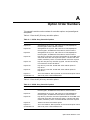
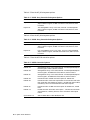
A Option Order Numbers
B Command Line Interpreter
B.1
CLI Commands . . . . . . . . . . . . . . . . . . . . .
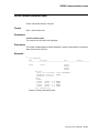
ADD CDROM . . . . . . . . . . . . . . . . . . . . . . .
ADD DISK . . . . . . . . . . . . . . . . . . . . . . . . .
ADD LOADER . . . . . . . . . . . . . . . . . . . . . .
ADD MIRRORSET . . . . . . . . . . . . . . . . . . .
ADD OPTICAL . . . . . . . . . . . . . . . . . . . . .
ADD PASSTHROUGH . . . . . . . . . . . . . . . .
ADD RAIDSET . . . . . . . . . . . . . . . . . . . . .
ADD SPARESET . . . . . . . . . . . . . . . . . . . .
ADD STRIPESET . . . . . . . . . . . . . . . . . . .
ADD TAPE . . . . . . . . . . . . . . . . . . . . . . . . .
ADD UNIT . . . . . . . . . . . . . . . . . . . . . . . . .
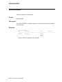
CLEAR_ERRORS CLI . . . . . . . . . . . . . . . .
CLEAR_ERRORS INVALID_CACHE . . . . .
CLEAR_ERRORS LOST_DATA . . . . . . . . .
CLEAR_ERRORS UNKNOWN . . . . . . . . .
CLEAR_ERRORS UNWRITEABLE_DATA
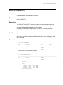
DELETE container-name . . . . . . . . . . . . . .
DELETE FAILEDSET . . . . . . . . . . . . . . . .
DELETE SPARESET . . . . . . . . . . . . . . . . .
DELETE unit-number . . . . . . . . . . . . . . . .
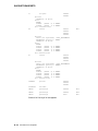
DIRECTORY . . . . . . . . . . . . . . . . . . . . . . .
EXIT . . . . . . . . . . . . . . . . . . . . . . . . . . . . .
.
.
.
.
.
.
.
.
.
.
.
.
.
.
.
.
.
.
.
.
.
.
.
.
.
.
.
.
.
.
.
.
.
.
.
.
.
.
.
.
.
.
.
.
.
.
.
.
.
.
.
.
.
.
.
.
.
.
.
.
.
.
.
.
.
.
.
.
.
.
.
.
.
.
.
.
.
.
.
.
.
.
.
.
.
.
.
.
.
.
.
.
.
.
.
.
.
.
.
.
.
.
.
.
.
.
.
.
.
.
.
.
.
.
.
.
.
.
.
.
.
.
.
.
.
.
.
.
.
.
.
.
.
.
.
.
.
.
.
.
.
.
.
.
.
.
.
.
.
.
.
.
.
.
.
.
.
.
.
.
.
.
.
.
.
.
.
.
.
.
.
.
.
.
.
.
.
.
.
.
.
.
.
.
.
.
.
.
.
.
.
.
.
.
.
.
.
.
.
.
.
.
.
.
.
.
.
.
.
.
.
.
.
.
.
.
.
.
.
.
.
.
.
.
.
.
.
.
.
.
.
.
.
.
.
.
.
.
.
.
.
.
.
.
.
.
.
.
.
.
.
.
.
.
.
.
.
.
.
.
.
.
.
.
.
.
.
.
.
.
.
.
.
.
.
.
.
.
.
.
.
.
.
.
.
.
.
.
.
.
.
.
.
.
.
.
.
.
.
.
.
.
.
.
.
.
.
.
.
.
.
.
.
.
.
.
.
.
.
.
.
.
.
.
.
.
.
.
.
.
.
.
.
.
.
.
.
.
.
.
.
.
.
.
.
.
.
.
.
.
.
.
.
.
.
.
.
.
.
.
.
.
.
.
.
.
.
.
.
.
.
.
.
.
.
.
.
.
.
.
.
.
.
.
.
.
.
.
.
.
.
.
.
.
.
.
.
.
.
.
.
.
.
.
.
.
.
.
.
.
.
.
.
.
.
.
.
.
.
.
.
.
.
.
.
.
.
.
.
.
.
.
.
.
.
.
.
.
.
.
.
.
.
.
.
.
.
.
.
.
.
.
.
.
.
.
.
.
.
.
.
.
.
.
.
.
.
.
.
.
.
.
.
.
.
.
.
.
.
.
.
.
.
.
.
.
.
.
.
.
.
.
.
.
.
.
.
.
.
.
.
.
.
.
.
.
.
.
.
.
.
.
.
.
.
.
.
.
.
.
.
.
.
.
.
.
.
.
.
.
.
.
.
.
.
.
.
.
.
.
.
.
.
.
.
.
.
.
.
.
.
.
B–1
B–2
B–3
B–5
B–6
B–8
B–10
B–11
B–13
B–14
B–15
B–16
B–27
B–28
B–29
B–30
B–31
B–32
B–33
B–34
B–35
B–36
B–37
ix
HELP . . . . . . . . . . . . . . . . . . . . . . . . . . . . . . . . . .
INITIALIZE . . . . . . . . . . . . . . . . . . . . . . . . . . . . .
LOCATE . . . . . . . . . . . . . . . . . . . . . . . . . . . . . . .
MIRROR disk-device-name1 container-name . . . .
REDUCE disk-device-name1 [disk-device-nameN]
RENAME . . . . . . . . . . . . . . . . . . . . . . . . . . . . . . .
RESTART OTHER_CONTROLLER . . . . . . . . . . .
RESTART THIS_CONTROLLER . . . . . . . . . . . . .
RETRY_ERRORS UNWRITEABLE_DATA . . . . .
RUN . . . . . . . . . . . . . . . . . . . . . . . . . . . . . . . . . . .
SELFTEST OTHER_CONTROLLER . . . . . . . . . .
SELFTEST THIS_CONTROLLER . . . . . . . . . . . .
SET disk-container-name . . . . . . . . . . . . . . . . . . .
SET FAILOVER . . . . . . . . . . . . . . . . . . . . . . . . . .
SET mirrorset-container-name . . . . . . . . . . . . . . .
SET NOFAILOVER . . . . . . . . . . . . . . . . . . . . . . .
SET OTHER_CONTROLLER . . . . . . . . . . . . . . .
SET RAIDset-container-name . . . . . . . . . . . . . . . .
SET THIS_CONTROLLER . . . . . . . . . . . . . . . . .
SET unit-number . . . . . . . . . . . . . . . . . . . . . . . . .
SHOW CDROMS . . . . . . . . . . . . . . . . . . . . . . . . .
SHOW cdrom-container-name . . . . . . . . . . . . . . .
SHOW DEVICES . . . . . . . . . . . . . . . . . . . . . . . . .
SHOW DISKS . . . . . . . . . . . . . . . . . . . . . . . . . . .
SHOW disk-container-name . . . . . . . . . . . . . . . . .
SHOW FAILEDSET . . . . . . . . . . . . . . . . . . . . . . .
SHOW LOADERS . . . . . . . . . . . . . . . . . . . . . . . .
SHOW loader-container-name . . . . . . . . . . . . . . .
SHOW MIRRORSETS . . . . . . . . . . . . . . . . . . . . .
SHOW mirrorset-container-name . . . . . . . . . . . . .
SHOW OPTICALS . . . . . . . . . . . . . . . . . . . . . . . .
SHOW optical-container-name . . . . . . . . . . . . . . .
SHOW OTHER_CONTROLLER . . . . . . . . . . . . .
SHOW PASSTHROUGH . . . . . . . . . . . . . . . . . . .
SHOW passthrough-container-name . . . . . . . . . . .
SHOW RAIDSETS . . . . . . . . . . . . . . . . . . . . . . . .
SHOW raidset-container-name . . . . . . . . . . . . . . .
SHOW SPARESET . . . . . . . . . . . . . . . . . . . . . . . .
SHOW STORAGESETS . . . . . . . . . . . . . . . . . . . .
SHOW STRIPESETS . . . . . . . . . . . . . . . . . . . . . .
SHOW stripeset-container-name . . . . . . . . . . . . . .
SHOW TAPES . . . . . . . . . . . . . . . . . . . . . . . . . . .
SHOW tape-container-name . . . . . . . . . . . . . . . . .
SHOW THIS_CONTROLLER . . . . . . . . . . . . . . .
SHOW UNITS . . . . . . . . . . . . . . . . . . . . . . . . . . .
SHOW unit-number . . . . . . . . . . . . . . . . . . . . . . .
SHUTDOWN OTHER_CONTROLLER . . . . . . . .
x
.
.
.
.
.
.
.
.
.
.
.
.
.
.
.
.
.
.
.
.
.
.
.
.
.
.
.
.
.
.
.
.
.
.
.
.
.
.
.
.
.
.
.
.
.
.
.
.
.
.
.
.
.
.
.
.
.
.
.
.
.
.
.
.
.
.
.
.
.
.
.
.
.
.
.
.
.
.
.
.
.
.
.
.
.
.
.
.
.
.
.
.
.
.
.
.
.
.
.
.
.
.
.
.
.
.
.
.
.
.
.
.
.
.
.
.
.
.
.
.
.
.
.
.
.
.
.
.
.
.
.
.
.
.
.
.
.
.
.
.
.
.
.
.
.
.
.
.
.
.
.
.
.
.
.
.
.
.
.
.
.
.
.
.
.
.
.
.
.
.
.
.
.
.
.
.
.
.
.
.
.
.
.
.
.
.
.
.
.
.
.
.
.
.
.
.
.
.
.
.
.
.
.
.
.
.
.
.
.
.
.
.
.
.
.
.
.
.
.
.
.
.
.
.
.
.
.
.
.
.
.
.
.
.
.
.
.
.
.
.
.
.
.
.
.
.
.
.
.
.
.
.
.
.
.
.
.
.
.
.
.
.
.
.
.
.
.
.
.
.
.
.
.
.
.
.
.
.
.
.
.
.
.
.
.
.
.
.
.
.
.
.
.
.
.
.
.
.
.
.
.
.
.
.
.
.
.
.
.
.
.
.
.
.
.
.
.
.
.
.
.
.
.
.
.
.
.
.
.
.
.
.
.
.
.
.
.
.
.
.
.
.
.
.
.
.
.
.
.
.
.
.
.
.
.
.
.
.
.
.
.
.
.
.
.
.
.
.
.
.
.
.
.
.
.
.
.
.
.
.
.
.
.
.
.
.
.
.
.
.
.
.
.
.
.
.
.
.
.
.
.
.
.
.
.
.
.
.
.
.
.
.
.
.
.
.
.
.
.
.
.
.
.
.
.
.
.
.
.
.
.
.
.
.
.
.
.
.
.
.
.
.
.
.
.
.
.
.
.
.
.
.
.
.
.
.
.
.
.
.
.
.
.
.
.
.
.
.
.
.
.
.
.
.
.
.
.
.
.
.
.
.
.
.
.
.
.
.
.
.
.
.
.
.
.
.
.
.
.
.
.
.
.
.
.
.
.
.
.
.
.
.
.
.
.
.
.
.
.
.
.
.
.
.
.
.
.
.
.
.
.
.
.
.
.
.
.
.
.
.
.
.
.
.
.
.
.
.
.
.
.
.
.
.
.
.
.
.
.
.
.
.
.
.
.
.
.
.
.
.
.
.
.
.
.
.
.
.
.
.
.
.
.
.
.
.
.
.
.
.
.
.
.
.
.
.
.
.
.
.
.
.
.
.
.
.
.
.
.
.
.
.
.
.
.
.
.
.
.
.
.
.
.
.
.
.
.
.
.
.
.
.
.
.
.
.
.
.
.
.
.
.
.
.
.
.
.
.
.
.
.
.
.
.
.
.
.
.
.
.
.
.
.
.
.
.
.
.
.
.
.
.
.
.
.
.
.
.
.
.
.
.
.
.
.
.
.
.
.
.
.
.
.
.
.
.
.
.
.
.
.
.
.
.
.
.
.
.
.
.
.
.
.
.
.
.
.
.
.
.
.
.
.
.
.
.
.
.
.
.
.
.
.
.
.
.
.
.
.
.
.
.
.
.
.
.
.
.
.
.
.
.
.
.
.
.
.
.
.
.
.
.
.
.
.
.
.
.
.
.
.
.
.
.
.
.
.
.
.
.
.
.
.
.
.
.
.
.
.
.
.
.
.
.
.
.
.
.
.
.
.
.
.
.
.
.
.
.
.
.
.
.
.
.
.
.
.
.
.
.
.
.
.
.
.
.
.
.
.
.
.
.
.
.
.
.
.
.
.
.
.
.
.
.
.
.
.
.
.
.
.
.
.
.
.
.
.
.
.
.
.
.
.
.
.
.
.
.
.
.
.
.
.
.
.
.
.
.
.
.
.
.
.
.
.
.
.
.
.
.
.
.
.
B–38
B–39
B–41
B–43
B–45
B–47
B–48
B–50
B–53
B–54
B–55
B–57
B–59
B–60
B–62
B–65
B–66
B–73
B–75
B–82
B–92
B–93
B–94
B–95
B–96
B–97
B–98
B–99
B–100
B–102
B–103
B–104
B–105
B–107
B–108
B–109
B–111
B–112
B–113
B–115
B–117
B–118
B–119
B–120
B–123
B–124
B–125
B.2
B.2.1
B.2.2
B.2.3
B.2.4
B.3
SHUTDOWN THIS_CONTROLLER
UNMIRROR disk-device-name . . . . .
CLI Messages . . . . . . . . . . . . . . . . . .
Error Conventions . . . . . . . . . . .
CLI Error Messages . . . . . . . . . .
Warning Conventions . . . . . . . . .
CLI Warning Messages . . . . . . .
Device Configuration Examples . . . .
.
.
.
.
.
.
.
.
.
.
.
.
.
.
.
.
.
.
.
.
.
.
.
.
.
.
.
.
.
.
.
.
.
.
.
.
.
.
.
.
.
.
.
.
.
.
.
.
.
.
.
.
.
.
.
.
.
.
.
.
.
.
.
.
.
.
.
.
.
.
.
.
.
.
.
.
.
.
.
.
.
.
.
.
.
.
.
.
.
.
.
.
.
.
.
.
.
.
.
.
.
.
.
.
.
.
.
.
.
.
.
.
.
.
.
.
.
.
.
.
.
.
.
.
.
.
.
.
.
.
.
.
.
.
.
.
.
.
.
.
.
.
.
.
.
.
.
.
.
.
.
.
.
.
.
.
.
.
.
.
.
.
.
.
.
.
.
.
.
.
.
.
.
.
.
.
.
.
.
.
.
.
.
.
.
.
.
.
.
.
.
.
.
.
.
.
.
.
.
.
.
.
.
.
.
.
.
.
.
.
.
.
.
.
.
.
.
.
.
.
.
.
.
.
.
.
.
.
.
.
.
.
B–127
B–129
B–130
B–130
B–130
B–150
B–150
B–154
No Cache Module Installed . . . . . . . . . . . . . . . . . . . . . . . . . . . .
Version 1 32-MB Read Cache Module . . . . . . . . . . . . . . . . . . . .
Version 2 32-MB Write-Back Cache Module . . . . . . . . . . . . . . . .
CLI EXIT Command Message . . . . . . . . . . . . . . . . . . . . . . . . . .
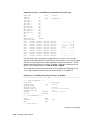
Using All Functions . . . . . . . . . . . . . . . . . . . . . . . . . . . . . . . . . .
Using All Defaults (Read-Only) . . . . . . . . . . . . . . . . . . . . . . . . .
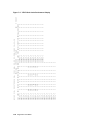
Using Auto-Configure with Half of the All Units Option . . . . . .
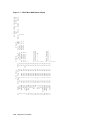
Using Auto-Configure with the All Units Option . . . . . . . . . . . .
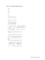
Using Auto-Configure on an HSZ Controller . . . . . . . . . . . . . . .
Using the All Units Option on an HSZ40 Controller . . . . . . . . .
Using All Defaults on an HSZ40 Controller . . . . . . . . . . . . . . . .
Using All Functions . . . . . . . . . . . . . . . . . . . . . . . . . . . . . . . . .
Using All Defaults . . . . . . . . . . . . . . . . . . . . . . . . . . . . . . . . . . .
Cloning a Single Device Unit . . . . . . . . . . . . . . . . . . . . . . . . . . .
Cloning a Stripeset . . . . . . . . . . . . . . . . . . . . . . . . . . . . . . . . . .
Cloning a Mirrorset . . . . . . . . . . . . . . . . . . . . . . . . . . . . . . . . . .
Cloning a Striped Mirrorset . . . . . . . . . . . . . . . . . . . . . . . . . . . .
OpenVMS Alpha V6.1 ERF Error Log Report . . . . . . . . . . . . . .
OpenVMS VAX ERF Error Log That Did Not Decode Fully . . . .
DECevent Bit-to-Text Translation Error Event Report . . . . . . .
uerf HSZ40 Array Controller Error Event Log . . . . . . . . . . . . . .
uerf Utility Error Event Using the -Z Qualifier . . . . . . . . . . . . .
Creating Device Special Files (NATIVE SCSI Host Adapter) . . .
Creating Device Special Files (SCSI Host Adapter) . . . . . . . . . .
SCSI Bus Number Determination . . . . . . . . . . . . . . . . . . . . . . .
Controller Host Side SCSI IDs of 0, 1, 2, and 3 . . . . . . . . . . . . .
Calculating the Minor Number for Device Special Files . . . . . . .
Mknod Examples . . . . . . . . . . . . . . . . . . . . . . . . . . . . . . . . . . . .
How MAKEDEV Calculates the Minor Number . . . . . . . . . . . . .
Initial Single Controller Configuration of an HSD30 Controller .
Initial Dual-Redundant Controller Configuration of an HSJ
Controller . . . . . . . . . . . . . . . . . . . . . . . . . . . . . . . . . . . . . . . . . .
Initial Single Controller Configuration of an HSZ Controller . . .
.
.
.
.
.
.
.
.
.
.
.
.
.
.
.
.
.
.
.
.
.
.
.
.
.
.
.
.
.
.
.
.
.
.
.
.
.
.
.
.
.
.
.
.
.
.
.
.
.
.
.
.
.
.
.
.
.
.
.
.
.
.
.
.
.
.
.
.
.
.
.
.
.
.
.
.
.
.
.
.
.
.
.
.
.
.
.
.
.
.
.
.
.
.
.
.
.
.
.
.
.
.
.
.
.
.
.
.
.
.
.
.
.
.
.
.
.
.
.
.
.
.
.
.
.
.
.
.
.
.
.
.
.
.
.
.
.
.
.
.
.
.
.
.
.
.
.
.
.
.
4–32
4–32
4–33
5–6
7–6
7–9
7–10
7–11
7–12
7–14
7–16
7–19
7–20
7–87
7–89
7–92
7–96
8–10
8–12
8–14
8–18
8–20
8–24
8–25
8–28
8–34
8–35
8–35
8–37
B–154
.....
.....
B–154
B–155
Glossary
Index
Examples
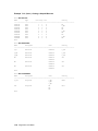
4–1
4–2
4–3
5–1
7–1
7–2
7–3
7–4
7–5
7–6
7–7
7–8
7–9
7–10
7–11
7–12
7–13
8–1
8–2
8–3
8–4
8–5
8–6
8–7
8–8
8–9
8–10
8–11
8–12
B–1
B–2
B–3
xi
B–4
B–5
B–6
B–7
B–8
B–9
B–10
B–11
B–12
B–13
B–14
Setting the Terminal Speed and Parity . . . . . . . . . . . . . . . . . .
Creating a Unit from a Disk Device . . . . . . . . . . . . . . . . . . . . .
Creating a Unit from a Tape Device . . . . . . . . . . . . . . . . . . . . .
Creating a Unit from a Four-Member Stripeset . . . . . . . . . . . .
Creating a Unit from a Five-Member RAIDset . . . . . . . . . . . .
Creating a Unit from a Disk Device and Setting the Write
Protection . . . . . . . . . . . . . . . . . . . . . . . . . . . . . . . . . . . . . . . . .
Setting the Write Protection for an Existing Unit . . . . . . . . . .
Renumbering Disk Unit 0 to Disk Unit 100 . . . . . . . . . . . . . . .
Creating a Transportable Unit from a Disk Device . . . . . . . . .
Changing the Replacement Policy of a RAIDset . . . . . . . . . . . .
Deleting the Unit, Stripeset, and All Disks Associated with a
Stripeset . . . . . . . . . . . . . . . . . . . . . . . . . . . . . . . . . . . . . . . . .
.
.
.
.
.
.
.
.
.
.
.
.
.
.
.
.
.
.
.
.
.
.
.
.
.
.
.
.
.
.
B–155
B–155
B–155
B–155
B–156
.
.
.
.
.
.
.
.
.
.
.
.
.
.
.
.
.
.
.
.
.
.
.
.
.
.
.
.
.
.
B–156
B–156
B–156
B–156
B–157
......
B–157
Figures
1–1
1–2
1–3
1–4
1–5
1–6
1–7
1–8
2–1
2–2
2–3
2–4
2–5
2–6
2–7
2–8
3–1
3–2
3–3
3–4
3–5
3–6
3–7
xii
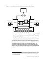
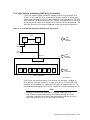
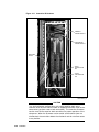
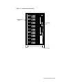
HS Array Controller Subsystem in an SW800-Series Data Center
Cabinet . . . . . . . . . . . . . . . . . . . . . . . . . . . . . . . . . . . . . . . . . . . . . . . .
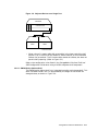
Dual-Redundant HSJ30 Array Controller Subsystem—Block
Diagram . . . . . . . . . . . . . . . . . . . . . . . . . . . . . . . . . . . . . . . . . . . . . . . .
Controller Storage Addressing . . . . . . . . . . . . . . . . . . . . . . . . . . . . . . .
Host Storage Addressing (HSZ40 Array Controllers) . . . . . . . . . . . . . .
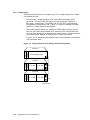
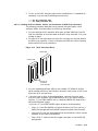
3½-Inch Storage SBB . . . . . . . . . . . . . . . . . . . . . . . . . . . . . . . . . . . . . .
5¼-Inch Storage SBB . . . . . . . . . . . . . . . . . . . . . . . . . . . . . . . . . . . . . .
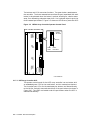
Controller Shelf with a Dual-Redundant HSJ40 Array Controller
Configuration . . . . . . . . . . . . . . . . . . . . . . . . . . . . . . . . . . . . . . . . . . . .
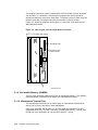
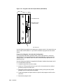
BA350–SB Fully Populated SBB Shelf . . . . . . . . . . . . . . . . . . . . . . . . .
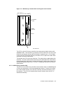
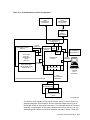
HS Array Controller Functional Block Diagram . . . . . . . . . . . . . . . . .
HSJ40 Array Controller OCP and Program Card Locations . . . . . . . . .
HSD30 Array Controller Operator Control Panel . . . . . . . . . . . . . . . . .
HSZ40–Bx Array Controller Operator Control Panel . . . . . . . . . . . . . .
HSJ Program Card and Eject Button Locations . . . . . . . . . . . . . . . . . .
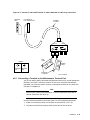
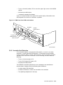
Location of the MMJ Maintenance Terminal Port for HSJ and HSD30
Array Controllers . . . . . . . . . . . . . . . . . . . . . . . . . . . . . . . . . . . . . . . . .
Phone Cable and Center-to-Offset Coupler for HSZ40–Bx Array
Controller MMJ Maintenance Terminal Port . . . . . . . . . . . . . . . . . . . .
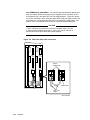
Dual-Redundant Controller Configuration . . . . . . . . . . . . . . . . . . . . . .
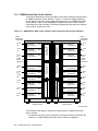
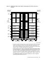
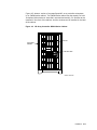
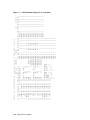
SW800-Series Data Center Cabinet Loading Sequence with No Tape
Positions . . . . . . . . . . . . . . . . . . . . . . . . . . . . . . . . . . . . . . . . . . . . . . .
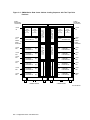
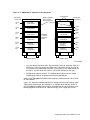
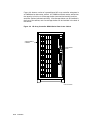
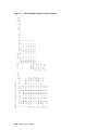
SW800-Series Data Center Cabinet Loading Sequence with Two Tape
Drive Positions . . . . . . . . . . . . . . . . . . . . . . . . . . . . . . . . . . . . . . . . . . .
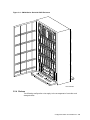
SW800-Series Data Center Cabinet Loading Sequence with Four Tape
Drive Positions . . . . . . . . . . . . . . . . . . . . . . . . . . . . . . . . . . . . . . . . . . .
SW500-Series Cabinet Loading Sequence . . . . . . . . . . . . . . . . . . . . . .
SW500-Series Controller/Storage Cabinet Shelf and Tape Drive
Locations . . . . . . . . . . . . . . . . . . . . . . . . . . . . . . . . . . . . . . . . . . . . . . .
SW300-Series Deskside RAID Enclosure . . . . . . . . . . . . . . . . . . . . . . .
Single Extension from Storage Shelf to Storage Shelf . . . . . . . . . . . . .
1–4
1–5
1–9
1–11
1–16
1–17
1–18
1–19
2–2
2–7
2–8
2–9
2–10
2–11
2–12
2–21
3–2
3–4
3–5
3–7
3–8
3–9
3–10
3–8
3–9
3–10
3–11
3–12
4–1
4–2
4–3
4–4
4–5
4–6
4–7
4–8
4–9
4–10
4–11
4–12
5–1
5–2
5–3
5–4
5–5
5–6
5–7
5–8
5–9
5–10
7–1
7–2
7–3
7–4
7–5
7–6
7–7
7–8
7–9
7–10
7–11
7–12
7–13
7–14
7–15
7–16
7–17
7–18
Adjacent Devices on a Single Port . . . . . . . . . . . . . . . . . . . . . . . . . .
SW300-Series Cabinet Controller/Storage Shelf . . . . . . . . . . . . . . . .
Balanced Devices Within Storage Shelves . . . . . . . . . . . . . . . . . . . .
Optimal Availability Configuration Example . . . . . . . . . . . . . . . . . .
SW300-Series Cabinet Shelf SCSI Buses . . . . . . . . . . . . . . . . . . . . .
Location of Program Card Eject Button . . . . . . . . . . . . . . . . . . . . . .
HSD30 Host Port Connector Mating Guide . . . . . . . . . . . . . . . . . . .
HS Array Controller SW500-Series Cabinet . . . . . . . . . . . . . . . . . . .
HS Array Controller SW800-Series Data Center Cabinet . . . . . . . .
SW300-Series Deskside RAID Enclosure . . . . . . . . . . . . . . . . . . . . .
DSSI Host Port Cable Connection . . . . . . . . . . . . . . . . . . . . . . . . . .
SCSI Host Port Cable Connection—Nonredundant Configuration . .
SCSI Host Port Cable Connection—Dual-Redundant Configuration .
Internal CI Cable with External CI Cables Attached for HSJ Array
Controllers . . . . . . . . . . . . . . . . . . . . . . . . . . . . . . . . . . . . . . . . . . . .
Trilink Connector Block . . . . . . . . . . . . . . . . . . . . . . . . . . . . . . . . . .
Controller ID Numbers . . . . . . . . . . . . . . . . . . . . . . . . . . . . . . . . . .
Program Card and Its Eject Button (ESD Shield) . . . . . . . . . . . . . .
Controller Initialization Flow Chart . . . . . . . . . . . . . . . . . . . . . . . . .
HSJ40 Operator Control Panel Reset and Port Buttons . . . . . . . . . .
HS Array Controllers Solid OCP LED Error Codes . . . . . . . . . . . . .
HS Array Controllers Flashing OCP LED Error Codes . . . . . . . . . .
EMU Front Panel LEDs and Switches . . . . . . . . . . . . . . . . . . . . . . .
SBB Warm Swap . . . . . . . . . . . . . . . . . . . . . . . . . . . . . . . . . . . . . . .
Cabinet Grounding Stud . . . . . . . . . . . . . . . . . . . . . . . . . . . . . . . . .
Four Front Bezel Screws, HSJxx Controller . . . . . . . . . . . . . . . . . . .
OCP Cable, HSJ Array Controller . . . . . . . . . . . . . . . . . . . . . . . . . .
Controller Shelf Rails . . . . . . . . . . . . . . . . . . . . . . . . . . . . . . . . . . . .
VTDPY Default Display for CI Controllers . . . . . . . . . . . . . . . . . . .
VTDPY Default Display for DSSI Controllers . . . . . . . . . . . . . . . . .
VTDPY Default Display for SCSI Controllers . . . . . . . . . . . . . . . . .
VTDPY Device Performance Display . . . . . . . . . . . . . . . . . . . . . . . .
VTDPY Unit Cache Performance Display . . . . . . . . . . . . . . . . . . . .
VTDPY Brief CI Status Display . . . . . . . . . . . . . . . . . . . . . . . . . . . .
VTDPY Brief DSSI Status Display . . . . . . . . . . . . . . . . . . . . . . . . .
VTDPY Brief SCSI Status Display . . . . . . . . . . . . . . . . . . . . . . . . . .
CFMENU Main Menu . . . . . . . . . . . . . . . . . . . . . . . . . . . . . . . . . . .
CFMENU Device Menu (Before Adding Devices) . . . . . . . . . . . . . . .
CFMENU Device Menu . . . . . . . . . . . . . . . . . . . . . . . . . . . . . . . . . .
CFMENU Mirrorset Menu . . . . . . . . . . . . . . . . . . . . . . . . . . . . . . .
CFMENU Stripeset Menu . . . . . . . . . . . . . . . . . . . . . . . . . . . . . . . .
CFMENU RAIDset Menu . . . . . . . . . . . . . . . . . . . . . . . . . . . . . . . .
CFMENU Spareset/Failedset Menu . . . . . . . . . . . . . . . . . . . . . . . .
CFMENU Passthrough Menu . . . . . . . . . . . . . . . . . . . . . . . . . . . . .
CFMENU Initialization Menu . . . . . . . . . . . . . . . . . . . . . . . . . . . .
CFMENU Unit Menu . . . . . . . . . . . . . . . . . . . . . . . . . . . . . . . . . . .
.
.
.
.
.
.
.
.
.
.
.
.
.
.
.
.
.
.
.
.
.
.
.
.
.
3–11
3–12
3–15
3–16
3–24
4–6
4–8
4–11
4–12
4–13
4–16
4–17
4–18
.
.
.
.
.
.
.
.
.
.
.
.
.
.
.
.
.
.
.
.
.
.
.
.
.
.
.
.
.
.
.
.
.
.
.
.
.
.
.
.
.
.
.
.
.
.
.
.
.
.
.
.
.
.
.
.
.
.
.
.
.
.
.
.
4–19
4–23
4–26
4–28
5–2
5–19
5–20
5–21
5–25
5–29
5–37
5–38
5–41
5–42
7–24
7–25
7–26
7–27
7–28
7–29
7–30
7–31
7–60
7–61
7–61
7–62
7–63
7–63
7–64
7–65
7–66
7–67
xiii
Tables
1
1–1
1–2
1–3
1–4
3–1
3–2
3–3
3–4
3–5
3–6
3–7
3–8
3–9
4–1
4–2
4–3
4–4
4–5
4–6
5–1
5–2
5–3
5–4
5–5
7–1
7–2
7–3
8–1
A–1
A–2
A–3
A–4
A–5
A–6
A–7
A–8
xiv
HS Array Controller Models . . . . . . . . . . . . . . . . . . . . . . . . . . . . . . . .
Summary of HS Array Controller Features . . . . . . . . . . . . . . . . . . . . .
HSJ Array Controller and Cache Module Specifications . . . . . . . . . . .
HSD30 Array Controller and Cache Module Specifications . . . . . . . . .
HSZ Array Controller and Cache Module Specifications . . . . . . . . . . .
High-Performance Devices per Port . . . . . . . . . . . . . . . . . . . . . . . . . . .
3½-Inch SBB Configurations, 6-Port Controllers . . . . . . . . . . . . . . . . .
3½-Inch SBB Configurations, 3-Port Controllers . . . . . . . . . . . . . . . . .
5¼-Inch SBB Configurations, 6-Port Controllers . . . . . . . . . . . . . . . . .
5¼-Inch SBB Configurations, 3-Port Controllers . . . . . . . . . . . . . . . . .
Small Shelf Count Configurations, 6-Port Controllers . . . . . . . . . . . . .
Small Shelf Count Configurations, 3-Port Controller . . . . . . . . . . . . . .
SW300-Series Cabinet Shelf Configuration . . . . . . . . . . . . . . . . . . . . .
SCSI Bus Maximum Lengths . . . . . . . . . . . . . . . . . . . . . . . . . . . . . . . .
StorageWorks Environmental Specifications . . . . . . . . . . . . . . . . . . . .
SCSI Bus Parameters . . . . . . . . . . . . . . . . . . . . . . . . . . . . . . . . . . . . .
Read and Write-Back Cache Upgrade Ordering Information for HSJ40
Array Controllers . . . . . . . . . . . . . . . . . . . . . . . . . . . . . . . . . . . . . . . . .
Read and Write-Back Cache Upgrade Ordering Information for HSJ30
Array Controllers . . . . . . . . . . . . . . . . . . . . . . . . . . . . . . . . . . . . . . . . .
Read and Write-Back Cache Upgrade Ordering Information for
HSD30 Array Controllers . . . . . . . . . . . . . . . . . . . . . . . . . . . . . . . . . . .
Read and Write-Back Cache Upgrade Ordering Information for
HSZ40–Ax and HSZ40–Bx Array Controllers . . . . . . . . . . . . . . . . . . . .
EMU Front Panel LEDS/Switches and Error Descriptions . . . . . . . . .
Controller Module Removal . . . . . . . . . . . . . . . . . . . . . . . . . . . . . . . . .
Cache Module Removal . . . . . . . . . . . . . . . . . . . . . . . . . . . . . . . . . . . .
Controller Module Replacement . . . . . . . . . . . . . . . . . . . . . . . . . . . . . .
Cache Module Replacement . . . . . . . . . . . . . . . . . . . . . . . . . . . . . . . . .
VTDPY Control Keys . . . . . . . . . . . . . . . . . . . . . . . . . . . . . . . . . . . . . .
VTDPY Commands . . . . . . . . . . . . . . . . . . . . . . . . . . . . . . . . . . . . . . .
Thread Description . . . . . . . . . . . . . . . . . . . . . . . . . . . . . . . . . . . . . . .
Minimum Operating System Support for HS Array Controllers . . . . . .
HSJ30 Array Controller Options . . . . . . . . . . . . . . . . . . . . . . . . . . . . .
HSJ40 Array Controller Options . . . . . . . . . . . . . . . . . . . . . . . . . . . . .
HSJ42 Array Controller Subsystem Options . . . . . . . . . . . . . . . . . . . .
HSJ44 Array Controller Subsystem Options . . . . . . . . . . . . . . . . . . . .
HSD30 Controller Options . . . . . . . . . . . . . . . . . . . . . . . . . . . . . . . . . .
HSZ40–Ax Controller Options . . . . . . . . . . . . . . . . . . . . . . . . . . . . . . .
HSZ40–Bx Controller Options . . . . . . . . . . . . . . . . . . . . . . . . . . . . . . .
HSJ40 Array Controller Preconfigured Subsystems Options . . . . . . . .
xv
1–13
1–14
1–15
1–15
3–14
3–18
3–19
3–20
3–21
3–22
3–22
3–23
3–24
4–2
4–9
4–34
4–34
4–34
4–35
5–26
5–36
5–39
5–40
5–43
7–22
7–22
7–36
8–2
A–1
A–1
A–2
A–2
A–2
A–3
A–3
A–5
Preface
Introduction
This StorageWorks Array Controllers HS Family of Array Controllers User’s Guide
contains instructions for installing and using HSJ30, HSJ40, HSD30, HSZ40–Ax,
and HSZ40–Bx array controllers.
For purposes of this manual, the term ‘‘HS array controller’’ refers to several
models, as shown in Table 1.
Table 1 HS Array Controller Models
Series
Model
Controllers not covered in this manual1
HSJ™
HSJ40
HSJ30
Any HSC™ controller
HSD30™
HSD30
HSD05 and related controllers
HSZ™
HSZ40–Ax
HSZ40–Bx
HSZ10 and related controllers
1 The
controllers listed in this column are not part of the HS array controller family.
The HSZ40–Bx is an enhanced verion of the HSZ40–Ax array controller. The
–Bx version allows firmware to be downline loaded to its program card. The
HSZ40–Ax will never support program card code load.
Intended Audience
This manual is intended for customers, system managers, and Digital
Multivendor Customer Services engineers responsible for installing and using HS
array controller subsystems.
Structure
This manual is organized as follows:
Chapter 1
Provides an overview of the HS family of array controllers, physical
descriptions of HS array controllers, storage addressing, controller features,
a discussion of the StorageWorks shelves and cabinets that house HS array
controllers, module specification tables, and host protocols.
Chapter 2
Provides a technical hardware overview of HS array controllers and a
summary of how the hardware (including read and write-back cache
modules, OCPs, and program cards) and firmware works. A description of
the failover process for HSJ, HSD30, and HSZ array controllers is included.
xv
Chapter 3
Describes the configuration rules and restrictions for standard and
nonstandard HS array controller subsystems. The maximum lengths for
host port cables is listed, as well as supported host adapters for each
controller model.
Chapter 4
Describes site preparation requirements, personnel and tools needed
for installation, electrostatic discharge protection, subsystem component
handling guidelines, preconfigured subsystem array controller/cache module
installation procedure references, and a method for determining your cache
module type.
Chapter 5
Describes array controller initialization, how to set subsystem configuration
parameters from the command line interpreter (CLI), when to use
TRANSPORTABLE and NOTRANSPORTABLE qualifiers, customer
acceptance tests with power applied, how to locate and read fault LEDs
on the operator control panel (OCP), SBB status LEDs, EMU, device
warm swap and array controller warm swap (C_SWAP) procedures, array
controller/cache module remove/replace procedures, controller SHUTDOWN
and host operating system DISMOUNT commands.
Chapter 6
Lists the supported RAID levels with brief descriptions for the Version 2.5
HS Operating firmware (HSOF) release. Describes how to use RAIDsets
and gives examples for adding, deleting, moving, and showing RAIDsets.
Gives RAIDset rules and important information about RAIDsets. Describes
stripesets, sparesets, and failedsets. Describes how to use mirrorsets and
striped mirrorsets.
Chapter 7
Describes when HS array controllers initialize, how to run online diagnostics
and user utilities, and run local controller programs such as, DILX, TILX,
VTDPY, firmware licensing system (FLS), controller warm swap (C_SWAP),
CONFIG, HSZterm, fault manager utility (FMU), CFMENU, Code Load
/Code Patch (CLCP) utility, and the CLONE utility. Describes command
disks and how to create them.
Chapter 8
Describes the operating system support for HS array controllers, as well
as restrictions and comments for each operating system. Gives a general
description of error log report tools including: ERF, DECevent, and UERF.
Describes how to configure HSZ array controllers under the DEC OSF/1
operating system.
Appendix A
Lists HS array controller option order numbers.
Appendix B
Gives the HS array controller command line interpreter (CLI) specification
in its entirety, and shows some examples.
Glossary
Defines acronyms and other terms specific to StorageWorks HS Family of
Array Controllers and associated cabinets and shelves.
Related Documentation
The following table lists documents that contain information related to this
product:
xvi
Document Title
Order Number
DECevent Analysis and Notification Utility for OpenVMS User
and Reference Guide
AA–Q73LA–TE
DECevent Installation Guide
AA–Q73JA–TE
DECevent Translation and Reporting Utility for OpenVMS User
and Reference Guide
AA–Q73KA-TE
HSJ30/40 Firmware Array Controller Software Product
Description (SPD47.26.07) for V2.5 HSOF
AE–PYTGH–TE
Document Title
Order Number
HSD30 Firmware Array Controller Software Product Description
(SPD 53.53.03) for V2.5 HSOF
AE–Q6HKD–TE
HSZ40 Firmware Array Controller Software Product Description
(SPD 53.54.04) for V2.5 HSOF
AE–Q6HME–TE
HS Family of Array Controllers Optional Operating Firmware
(HSOF) Software Product Description (SPD 53.38.01) for V2.5
AE–QDA4B–TE
StorageWorks Array Controllers HS Family of Array Controllers
Service Manual (Use revision D01 for HSOF Version 2.5.)
EK–HSFAM–SV
StorageWorks Array Controllers HSJ30/40 Array Controller
Operating Firmware Release Notes (Use revision L01 for HSOF
Version 2.5)
EK–HSFAM–RN
StorageWorks Array Controllers HSD30 Array Controller
Operating Firmware Release Notes (User revision D01 for HSOF
Version 2.5)
EK–HSD30–RN
StorageWorks Array Controllers HSZ40 Array Controller
Operating Firmware Release Notes (Use revision E01 for HSOF
Version 2.5)
EK–HSZ40–RN
StorageWorks BA350–MA Controller Shelf User’s Guide
EK–350MA–UG
StorageWorks Configuration Manager for DEC OSF/1 Installation
Guide
AA–QC38A–TE
StorageWorks Configuration Manager for DEC OSF/1 System
Manager’s Guide for HSZterm
AA–QC39A–TE
StorageWorks Family StorageWorks Building Blocks User’s Guide
EK–SBB35–UG
StorageWorks Metric Shelf Bracket Kit Installation Guide
EK–35XRD–IG
StorageWorks Solutions Configuration Guide
EK–BA350–CG
StorageWorks Solutions Shelf and SBB User’s Guide
EK–BA350–UG
StorageWorks Solutions SW300-Series RAID Enclosure
Installation and User’s Guide
EK–SW300–UG
StorageWorks SW500-Series Cabinet Installation and User’s Guide
EK–SW500–IG
StorageWorks SW500-Series Cabinet Cable Distribution Unit
Installation Guide
EK–SW5CU–IG
StorageWorks SW800-Series Data Center Cabinet Cable
Distribution Unit Installation Sheet
EK–SWCDU–IS
StorageWorks SW800-Series Data Center Cabinet Installation and
User’s Guide
EK–SW800–IG
The Digital Guide to RAID Storage Technology
EC–B1960–45
The RAIDBOOK—A Source for RAID Technology
RAID Advisory Board
VAXcluster Console System User’s Guide
AA–GV45D–TE
VAXcluster Systems Guidelines for VAXcluster System
Configurations
EK–VAXCS–CG
xvii
Documentation Conventions
The following conventions are used in this manual:
xviii
boldface type
Boldface type in examples indicates user input. Boldface type in
text indicates the first instance of terms defined in either the text,
in the glossary, or both. Boldface type is used also for controller
model names to help the reader pick out the information for their
specific model in procedures that talk about the differences of each
model.
italic type
Italic type indicates emphasis and complete manual titles.
UPPERCASE
Words in uppercase text indicate a command, the name of a file,
or an abbreviation for a system privilege.
Ctrl/x
Ctrl/x indicates that you hold down the Ctrl key while you press
another key, indicated by x.
1
Introduction to HS Array Controllers
This chapter contains an overview of the HS family of array controllers. A list of
key attributes for each controller and the controller shelves are provided. This
chapter also provides a brief description of the protocols used with each controller
model’s functional environment.
1.1 Overview of HS Array Controllers
The HS array controllers are a family of controller products designed to provide
open interface interconnection for the following:
•
Digital Equipment Corporation small computer system interface (SCSI)
devices:
Solid state disks
Disk drives
Tape drives
Tape loaders
CD–ROM drives
•
Redundant array of independent disks (RAID)
Note
The HS array controllers support a variety of storage devices. Refer
to product-specific release notes and software product descriptions for
supported devices for each controller model (HSJ30/40, HSD30, HSZ40–
Ax, or HSZ40–Bx array controllers). Any limitations or restrictions not
already provided in this manual are provided in the product-specific
release notes for your HSOF version number.
The HS family of array controllers is an integral part of the StorageWorks array
subsystem. HS array controllers provide high performance, high availability, and
high connectivity access to SCSI–2 devices from the host by way of a variety of
interconnects. The interconnects discussed in this manual are CI, DSSI, and
SCSI for the HSJ30/HSJ40, HSD30, and HSZ array controllers respectively.
These controllers support various operating systems as described in controllerspecific release notes, software product descriptions (SPDs), and in Chapter 8 of
this manual.
Introduction to HS Array Controllers 1–1
Note
HSJ30 and HSJ40 array controllers hereafter are referred to as HSJ
array controllers unless the text is controller-model specific.
HSZ40–Ax and HSZ40–Bx array controllers hereafter are referred to as
HSZ array controllers unless the text is controller-model specific.
1.2 Housing for HS Array Controllers
The controller modules and associated read and write-back cache modules mount
in a controller shelf.1 Each controller shelf supports up to two controller modules,
two read or write-back cache modules, and one or two shelf power supplies.
The controller shelf slides into slots in StorageWorks cabinets. The same array
cabinets contain storage shelves that hold the storage devices supported by the
controllers.
The SCSI–2 device cables (also known as port or bus cables) are connected to
the controller shelf backplane, routed out the front of the controller shelf, and
routed into the front of storage shelves (such as the BA350–SB shelf) that hold
the SCSI–2 devices.
At the lowest level, a SCSI–2 device fits into a plastic carrier. The combination
of the plastic carrier and the storage device is called a StorageWorks building
block (SBB). These SBB carriers slide into slots in the storage shelves.
1.3 Physical Description of HS Array Controllers
The following sections describe the physical attributes of each HS array controller
model including HSJ (both HSJ30 and HSJ40 array controllers), HSD30, and
HSZ (HSZ40–Ax and HSZ40–Bx array controllers).
1.3.1 HSJ30 and HSJ40 Array Controllers Physical Description
The physical HSJ40 array controller module has three SCSI–2 shelf backplane
connectors with the following features:
•
Each shelf backplane connector supports two SCSI–2 ports for a total of six
SCSI–2 ports (buses) for the HSJ40 controller.
The HSJ30 array controller supports three SCSI–2 ports. The command line
interpreter does not allow any configurations past port 3 to be entered for
HSJ30 controllers (devices on ports 4, 5, and 6 are ignored).
•
Each SCSI–2 port supports up to six (or seven) SCSI–2 devices,2 , depending
on the subsystem configuration.
Note
The HSJ30 controller supports up to 18 devices in a dual-redundant
configuration. Lower availability configurations can support up to 21
devices (seven per SCSI–2 port) if nonredundant power is not used. Other
1
2
Controllers and their cache modules can reside in either a BA350–MA controller shelf or
a SW300-series cabinet shelf.
An HSJ40 dual-redundant controller configuration supports up to 36 devices. Lower
availability configurations can support up to 42 devices (seven per SCSI–2 port) but this
will sacrifice a convenient upgrade to any of the possible higher availability options, such
as redundant power. For this reason, Digital does not recommend this configuration.
1–2 Introduction to HS Array Controllers
availability options also are sacrificed. Digital does not recommend this
configuration.
•
The six SCSI–2 device cables (three for HSJ30) from the controller shelf can
be routed to more than one SBB shelf as desired, taking into consideration
prescribed configuration rules and restrictions as listed in Chapter 3.
The HSJ array controllers consist of a single module that can be configured alone
(nonredundant) or with a second like controller module for dual-redundant
availability, and a read or write-back cache module (one for each controller
module).
The HSJ array controllers interconnect to the host by way of Digital’s CI
interface. An internal CI host port cable connects to each controller and
routes through the cabinet, exiting at the back of the cabinet near the floor.
Four external (blue) CI cables connect to the end of each internal CI host port
connector and then route to a star coupler. From the star coupler, the cables route
to the host computer. Refer to the VAXcluster Systems Guidelines for VAXcluster
System Configurations manual for supported configurations with star couplers.
See Section 4.6.2.1 for installation instructions for CI host port cables.
The combination of HSJ array controllers in controller shelves, storage shelves
with their power supplies, assorted SCSI–2 device and CI cables, and cable
distribution units (CDU) compose the HSJ array controller subsystem. Refer to
the VAXcluster Systems Guidelines for VAXcluster System Configurations manual
for supported configurations with storage components.
Figure 1–1 shows an HS array controller subsystem configuration in an SW800series (1700 mm high) data center cabinet (front view). Controller subsystems
also are available in SW500-series (1100 mm high) cabinets and SW300-series
deskside RAID enclosure cabinets.
Introduction to HS Array Controllers 1–3
Figure 1–1 HS Array Controller Subsystem in an SW800-Series Data Center
Cabinet
CONTROLLERS
800-SERIES
CABINET
DEVICE
CXO-4114A-MC
Figure 1–2 depicts a block diagram of a dual-redundant HSJ30 controller
subsystem. In an HSJ30 dual-redundant configuration, two controllers attach to
three SCSI–2 buses within the same controller shelf.
Note
The same block diagram applies to the HSJ40 controller, except the
HSJ40 controller has six SCSI–2 buses.
1.3.2 HSD30 Array Controller Physical Description
The physical HSD30 array controller module has three shelf backplane connectors
with the following features:
•
One SCSI–2 shelf backplane connector supports two SCSI–2 ports, and
a second SCSI–2 connector supports one SCSI–2 port for a total of three
SCSI–2 ports (buses). The third connector is not used.
1–4 Introduction to HS Array Controllers
Figure 1–2 Dual-Redundant HSJ30 Array Controller Subsystem—Block Diagram
HOST
CPU
CI
CI
MAINTENANCE
TERMINAL EIA423
PORT
HSJ30
CONTROLLER
(OPTIONAL)
3
2
1
CI
STAR
COUPLER
READ OR
WRITEBACK
CACHE
READ OR
WRITEBACK
CACHE
FAILOVER COMMUNICATION
HSJ30
CONTROLLER
MAINTENANCE
EIA- TERMINAL
423
PORT
(OPTIONAL)
1
2
3
CXO-3699D-MC
•
Each SCSI–2 port supports up to six (or seven) SCSI–2 devices,3 , depending
on the subsystem configuration.
•
The three SCSI–2 port cables from the controller shelf can be routed to
more than one storage shelf as desired, taking into consideration prescribed
configuration rules and restrictions as listed in Chapter 3.
The HSD30 array controller consists of a single module that can be configured
alone (nonredundant) (with its cache module) or with a second HSD30 controller
module (with its cache module) for dual-redundant availability.
The HSD30 array controller host port is an 8-bit wide DSSI interface. The
HSD30 array controller requires a DSSI trilink connector block (Digital part
number 12–39921–02) mounted on its host connector (which is included with each
controller), and requires external terminators (Digital part number 12–31281–01)
as appropriate. (See Section 4.6.2.2 for installation instructions for DSSI host
port cables.)
3
An HSD30 dual-redundant controller configuration supports up to 18 devices. Lower
availability configurations can support up to 21 devices (seven per SCSI–2 port) but this
will sacrifice a convenient upgrade to any of the possible higher availability options,
such as redundant power.
Introduction to HS Array Controllers 1–5
Supported configurations allow up to four HSD30 array controllers per DSSI bus
(for example, four nonredundant controllers, or two dual-redundant controller
pairs, or one dual-redundant controller pair and two nonredundant controllers).
Refer to the StorageWorks Array Controllers HSD30 Array Controller Operating
Firmware Release Notes for changes and/or restrictions.
Note
Separate buses are supported for an HSD30 array controller dualredundant configuration using the OpenVMS Version 6.1 and higher
operating system software.
The combination of HSD30 array controllers in controller shelves, storage shelves
with their power supplies, assorted SCSI–2 device and DSSI host cables, and
cable distribution units compose the HSD30 array controller subsystem. HSD30
array controller subsystems are available in SW800-series data center cabinets,
SW500-series cabinets, or SW300-series deskside enclosures.
DSSI Bus Rules
The following are DSSI bus rules for properly installing and operating your
HSD30 array controller subsystem:
•
All systems connected to the same DSSI bus must have a common
power/ground.
•
Each DSSI bus supports up to eight nodes. Each of the following counts as
one DSSI node:
•
–
A host DSSI adapter
–
An RF-disk controller interface
–
A TF-tape controller interface
–
An HSD30 array controller
–
An HSD05 controller
Each DSSI bus must be terminated at each end at all times; breaking the bus
while a cluster is operational can lead to data corruption.
Refer to the VAXcluster Systems Guidelines for VAXcluster System Configurations
manual for supported host configurations with DSSI controllers.
1.3.3 HSZ Array Controller Physical Description
The physical HSZ array controller module has three shelf backplane connectors
with the following features:
•
Each shelf backplane connector supports two SCSI–2 ports for a total of six
SCSI–2 ports (buses).
•
Each SCSI–2 port supports up to six (or seven) SCSI–2 devices,4 , depending
on the subsystem configuration.
4
An HSZ40 dual-redundant controller configuration supports up to 36 devices. Lower
availability configurations can support up to 42 devices (seven per SCSI–2 port) but this
will sacrifice a convenient upgrade to any of the possible higher availability options,
such as redundant power.
1–6 Introduction to HS Array Controllers
•
The six SCSI–2 port cables from the controller shelf can be routed to
more than one device shelf as desired, taking into consideration prescribed
configuration rules and restrictions as listed in Chapter 3.
The HSZ array controller consists of a single module that is configured alone
(nonredundant) or with a second like controller for dual-redundant availability in
the controller shelf. One read cache or write-back cache module is supported for
each controller module.
The HSZ array controller is supported in a single host environment, where the
host can have a 8-bit single-ended adapter or a 16-bit differential adapter. The
HSZ40 array controller host port is a 16-bit fast-wide-differential (FWD) SCSI–2
interface, which requires a DWZZA host adapter for those hosts that have 8-bit
single-ended adapters. (See Chapter 3 for supported host adapters.)
Note
Either a desktop (DWZZA–AA) or SBB (DWZZA–VA) DWZZA host
adapter can be used for hosts that require an 8-bit single-ended adapter.
Refer to the StorageWorks Solution Shelf and SBB User’s Guide for more
information about DWZZA-series SCSI–2 bus signal converters.
The HSZ array controller requires a SCSI–2 trilink connector block (Digital
part number 12–39921–01 or H885–AA) mounted on its host connector
(which is included with each controller), and requires external terminators
(H879–AA, 68-pin) as appropriate. See Section 4.6.2.3 for host port cable
installation instructions.
The combination of HSZ array controllers in a controller shelf, storage shelves
with their power supplies, assorted SCSI–2 device and SCSI–2 host cables, and
cable distribution units, compose the HSZ40 array controller subsystem. HSZ
array controller subsystems are available in SW800-series data center cabinets,
SW500-series cabinets, or SW300-series deskside enclosures.
HSZ40–Ax and HSZ40–Bx
There are two HSZ40 array controller module versions, the original
HSZ40–Ax and the later HSZ40–Bx. The HSZ40–Bx array controller
supports an environmental monitor unit (EMU) in an SW300-series
deskside RAID enclosure cabinet and has a center-keyed modified
modular jack (MMJ) maintenance terminal port connector.
1.4 Controller Host Interface Protocols
The CI (HSJ) and DSSI (HSD30) interfaces use MSCP and TMSCP as the storage
control protocols through which access to the controller-attached SCSI–2 devices
is obtained.
The SCSI FWD (HSZ) host interface uses the SCSI–2 protocol for a host to access
LUNs attached to the controller (the controller being a SCSI target as seen by
the host).
Introduction to HS Array Controllers 1–7
1.5 Addressing Storage Within the Subsystem
This section provides an overview of how a controller subsystem addresses
storage. Storage is seen in two different ways, depending on your perspective and
your controller model:
1. From the controller SCSI–2 device interface—At the physical device level
2. From the host interface—At the virtual device level
The following sections describe both levels of storage addressing.
1.5.1 Controller Storage Addressing
Note
This section on controller storage addressing applies to all controller
models except where noted.
Figure 1–3 shows a typical physical storage device interface for an HSZ40
array controller. Each of the controller’s six device ports supports a SCSI–2 bus
connected with up to six devices. The devices typically reside in a StorageWorks
BA350–Sx SBB shelf.
1–8 Introduction to HS Array Controllers
Figure 1–3 Controller Storage Addressing
HOST INTERFACE
CONTROLLER
DEVICE INTERFACE
PORT
1
PORT
2
PORT
3
PORT
4
PORT
5
CONTROLLER
PORT
ADDRESS
PORT
6
SCSI
BUS 1
SCSI
BUS 2
SCSI
BUS 6
SCSI
BUS 3
SCSI
BUS 4
SCSI
BUS 5
(OPTIONAL)
SCSI ID SCSI ID
SCSI ID
5
4
6
LUN 0
LUN 0
SCSI ID
3
SCSI ID
2
SCSI ID
1
SCSI ID
0
CONTROLLER
TARGET
ADDRESS
LUN 0
LUN 0
LUN 0
LUN 0
LUN 0
CONTROLLER
LUN
ADDRESS
DEVICE
4
DEVICE
3
DEVICE
2
DEVICE
1
DEVICE
0
LUN 1
DEVICE
6
DEVICE
5
StorageWorks STORAGE SHELF
(PHYSICAL DEVICES)
CXO-4596A-MC
HSJ and HSD30 array controllers support multiple LUNs per device port (and
nonzero (0) LUNs) for certain tape loader devices. For these devices, the loader
mechanism is addressed at LUN 1, and the tape drive mechanism is addressed
at LUN 0. Other than the supported tape loader devices, all controllers support
only one controller LUN per physical device or storageset. (A storageset is a
collection of containers, such as a stripeset, RAIDset, or mirrorset, that together
make up a separate container.) LUN 0 is the default controller LUN address for
each device. A container is a term used to describe any entity that is capable
Introduction to HS Array Controllers 1–9
of storing data, whether it is a physical device or a group of physical devices. A
disk, a stripeset, a RAIDset, or a mirrorset are examples of containers.
Controller Port Target LUN Addressing
Controller Port Target LUN (PTL) addressing is the process by which the
controller selects storage space within a specific, physical, storage device. The
process takes place in three steps:
1. The port selection—The controller selects the SCSI–2 bus port connected to a
particular device.
2. The target selection—The controller selects the device’s SCSI ID (that is, the
target) on that port (bus).
3. The LUN selection—The controller selects the desired LUN within that
physical device. In the current implementation, there is only one LUN on
each device, and that LUN address is always zero, except for the multi-LUN
tape loader support on HSJ and HSD30 array controllers as mentioned above.
Note that controller PTL addressing is always tied to a physical storage device.
1.5.2 Host Storage Addressing
Note
The information in this section applies to all controllers. However, see
Section 1.5.3 for specific information on how a SCSI host addresses
storage.
A typical host device interface consists of a number of host ports, each connected
to a bus containing devices. From the host perspective, the controller is one of
these devices.
To support certain high-level storage subsystem functions such as RAID, the
controller presents the entire physical device configuration (from Figure 1–3) to
the host as a group of host logical units. A host logical unit usually consists
of storage data being distributed throughout more than one physical device
(as with a RAIDset). The controller presents these logical units to the host as
individually-addressable, virtual devices. The user configures host logical units
using the CLI.
Note
Controller LUNs (devices) and host logical units may represent the same
structure, but only if the user configures controller devices in a one-to-one
relationship with host logical units. Note that stripesets, RAIDsets, and
mirrorsets cannot be configured in such a one-to-one relationship.
For this reason, host addressing is often tied to a virtual storage device (a
storageset).
1–10 Introduction to HS Array Controllers
1.5.3 Host Storage Addressing (HSZ Array Controllers)
Figure 1–4 shows a typical connection between an HSZ array controller and
its host. In this case, the SCSI–2 host device interface consists of device ports
(buses), each connected to a SCSI–2 bus containing up to eight devices. The HSZ
array controller resides on one of the SCSI–2 buses. A single HSZ array controller
can be assigned up to four SCSI target IDs on the bus (a dual-redundant pair also
can have up to four SCSI target IDs between them; they share the same four).
Figure 1–4 Host Storage Addressing (HSZ40 Array Controllers)
HOST
PORT
N
HOST
PORT
ADDRESS
PORT
1
SCSI
BUS N
SCSI
BUS 1
HOST
TARGET
ADDRESS
SCSI ID x
HOST INTERFACE
CONTROLLER
DEVICE INTERFACE
LUN
0
LUN
1
LUN
2
LUN
3
LUN
4
LUN
5
LUN
6
LUN
7
HOST
LUN
ADDRESS
(VIRTUAL DEVICES)
CXO-4107A-MC
A SCSI host also sees host logical units through the controller. However, in
SCSI systems, there can be only up to eight units per ID. For the HSZ array
controller, this translates as a maximum of 32 units, or eight per each ID. The
host addresses each logical unit by a SCSI logical unit number, also called a LUN.
Note
Although they share the same name, controller LUNs and SCSI
host LUNs are logical addresses for two different storage structures.
Controller LUNs exist only on the controller’s device interface, and SCSI
host LUNs exist only on a SCSI host’s device interface.
Introduction to HS Array Controllers 1–11
Controller LUNs and SCSI host LUNs may represent the same structure,
but only if the user configures (up to) eight controller devices in a one-toone unit relationship with the host. This situation rarely occurs under
normal operation.
Host Port Target LUN Addressing (HSZ Array Controllers)
Note
Non-SCSI hosts (CI, DSSI), though they access virtual devices, do not use
a PTL addressing scheme. Any unit seen by these hosts is simply called a
host logical unit (not a LUN).
Host addressing is the process by which a SCSI host selects a logical unit made
up of physical devices connected to an HSZ array controller. The process takes
place in four steps:
1. The adapter selection—The host selects the adapter with one (or more)
SCSI–2 busses.
2. The port selection—The host selects the SCSI–2 bus that has the HSZ
array controller connected to it (for adapters with two or more SCSI–2 bus
interfaces).
3. The target selection—The host selects one of the controller’s SCSI IDs (that
is, the targets) on that port (bus).
4. The LUN selection—The host addresses the controller with the LUN of the
desired host logical unit. The controller translates the LUN into the physical
device addresses required to allow the host access to the virtual device.
1.6 HSJ Array Controller Dual Data Link
The HSJ array controllers fully support dual data link (DDL) operations. That
is, they can have operations in progress simultaneously on both CI paths. Either
receive/receive, receive/transmit, or transmit/transmit operations can be active
at the same time. The only restriction on a DDL operation is that simultaneous
transmit and simultaneous receive operations cannot be active on the same
virtual circuit. The packets that are simultaneously active can be to any two
separate CI nodes, or a transmit and a receive operation can be active to the
same node if it also supports DDL operation. Each CI path (Path A and Path B)
runs in half duplex, that is, it can either be transmitting or receiving, but not
both at the same time.
1.7 HS Array Controller Features
The following text, as well as Table 1–1, provides a summary of the features of
HS array controllers.
Remote system management is performed through the use of the following:
•
DUP protocol for CI pass-through from the host to the controller’s CLI. The
HSJ and HSD30 array controllers support DUP connections.
1–12 Introduction to HS Array Controllers
•
HSZ array controllers can use a SCSI virtual terminal connection from a host
application utility called HSZterm (or StorageWorks HSZ40 Array Controller
Utility for DEC OSF/1 Version 1.0). Refer to the StorageWorks Configuration
Manager for DEC OSF/1 Installation Guide and the StorageWorks Manager
for DEC OSF/1 System Manager’s Guide for HSZterm for complete HSZterm
installation and operating instructions.
•
For HSJ and HSD30 array controllers, a special storage configuration for
communication with generic SCSI–2 devices is supported. The concept centers
around a virtual unit called a command disk, that allows an MSCP-based
host to control any physical SCSI–2 device. For details about the uses and
creation of a command disk, see Chapter 7.
Table 1–1 Summary of HS Array Controller Features
Feature
HSJ30
HSJ40
HSD30
HSZ40
Host bus
CI
CI
DSSI
SCSI–2 FWD
Host protocols
SCS, MSCP,
TMSCP, DUP
SCS, MSCP,
TMSCP, DUP
SCS, MSCP,
TMSCP, DUP
SCSI–2
Storage device protocol
SCSI–2
SCSI–2
SCSI–2
SCSI–2
Number of SCSI device
ports
3
6
3
6
Maximum number of
SCSI–2 devices
18 (or 211 )
36 (or 421 )
18 (or 211 )
36 (or 421 )
Controller shared
memory
8 MB
8 MB
8 MB
8 MB
Nonvolatile memory
(NVMEM)
32 KB
32 KB
32 KB
32 KB
Read cache module
16- or 32-MB
16- or 32-MB
16- or 32-MB
16- or 32-MB
Write-back cache module
16- or 32-MB
16- or 32-MB
16- or 32 MB
16- or 32-MB
RAID levels supported
RAID
0/1/0&1/3/5
RAID
0/1/0&1/3/5
RAID
0/1/0&1/3/5
RAID
0/1/0&1/3/5
Mixed disk and tape
support2
Yes
Yes
Yes
N/A
Sequential access tape
media loader
Yes
Yes
Yes
N/A
Dual-redundant
configurations
Yes
Yes
Yes
Yes
Program card firmware
update
Yes
Yes
Yes
Yes
Device warm swap
support
Yes
Yes
Yes
Yes
Controller warm swap
support
Yes
Yes
Yes
Yes
BBR and MSCP forced
error support
Yes
Yes
Yes
N/A
1A
dual-redundant controller configuration supports up to six devices per port. A nonredundant controller configuration
supports up to seven devices per port, but this sacrifices a convenient upgrade to high availability and redundant/backup
power supplies.
2 On
the same or different ports.
(continued on next page)
Introduction to HS Array Controllers 1–13
Table 1–1 (Cont.) Summary of HS Array Controller Features
Feature
HSJ30
HSJ40
HSD30
HSZ40
Tagged command
queuing
N/A
N/A
N/A
Yes
Error correction code
(ECC)
Correction of
program card
firmware
Correction of
program card
firmware
Correction of
program card
firmware
Correction of
program card
firmware
Error correction code
(ECC) on cache and
shared memory
Yes
Yes
Yes
Yes
Controller-based
exercisers for device
testing
Yes
Yes
Yes
Yes
Active device polling
Yes
Yes
Yes
N/A
Preferred path
preservation
Yes
Yes
Yes
N/A
Preferred ID
N/A
N/A
N/A
Yes
Random access tapes
/loaders
Yes
Yes
Yes
N/A
Command disk
(passthrough unit)
Yes
Yes
Yes
N/A
Direct print
Yes
Yes
Yes
Yes
Firmware code patch
Yes
Yes
Yes
Yes
Firmware code load
No
No
No
Yes
1.8 Controllers and Cache Modules Specifications
Tables 1–2, 1–3, and 1–4 list the physical and electrical specifications for the HS
array controllers and cache modules.
Table 1–2 HSJ Array Controller and Cache Module Specifications
Specification
Controller
Module
Typical
Controller
Module
Maximum
Read
Cache
16 MB
Read
Cache
32 MB
Write-Back
Cache
16 MB
Write-Back
Cache
32 MB
Width
12.5 inches
N/A
12.5 inches
12.5 inches
12.5 inches
12.5 inches
Depth
9.5 inches
N/A
7.75 inches
7.75
7.75 inches
7.75 inches
Power
Consumption
39.04 watts
45.58 watts
1.82 watts
2.02 watts
2.28 watts
2.48 watts
@ +5 V
6.2 A
7.1 A
360 mA
400 mA
360 mA
400 mA
1
40 mA1
@ +12 V
670 mA
840 mA
1 With
2 mA
2 mA
40 mA
fully charged batteries. If the batteries for your 16- or 32-MB write-back cache module are in a charging state, the
current at +12 V is 560 mA, which adds another 6.24 watts to the module power consumption.
1–14 Introduction to HS Array Controllers
Table 1–3 HSD30 Array Controller and Cache Module Specifications
Specification
Controller
Module
Typical
Controller
Module
Maximum
Read
Cache
16 MB
Read
Cache
32 MB
Write-Back
Cache
16 MB
Write-Back
Cache
32 MB
Width
12.5 inches
N/A
12.5 inches
12.5 inches
12.5 inches
12.5 inches
Depth
8.75 inches
N/A
7.75 inches
7.75 inches
7.75 inches
7.75 inches
Power
Consumption
20.76 watts
23.04 watts
1.82 watts
2.02 watts
2.28 watts
2.48 watts
@ +5 V
4.15 A
4.56 A
360 mA
400 mA
360 mA
400 mA
@ +12 V
01 mA
02 mA
2 mA
2 mA
40 mA1
40 mA1
1 With
fully charged batteries. If the batteries for your 16- or 32-MB write-back cache module are in a charging state, the
current at +12 V is 560 mA, which adds another 6.24 watts to the module power consumption.
Table 1–4 HSZ Array Controller and Cache Module Specifications
Specification
Controller
Module
Typical
Controller
Module
Maximum
Read
Cache
16 MB
Read
Cache
32 MB
Write-Back
Cache
16 MB
Write-Back
Cache
32 MB
Width
12.5 inches
N/A
12.5 inches
12.5 inches
12.5 inches
12.5 inches
Depth
8.75 inches
N/A
7.75 inches
7.75 inches
7.75 inches
7.75 inches
Power
Consumption
23.27 watts
25.84 watts
1.82 watts
2.02 watts
2.28 watts
2.48 watts
@ +5 V
4.63 A
5.12 A
360 mA
400 mA
360 mA
400 mA
1
40 mA1
@ +12 V
10 mA
20 mA
2 mA
2 mA
40 mA
1 With
fully charged batteries. If the batteries for your 16- or 32-MB write-back cache module are in a charging state, the
current at +12 V is 560 mA, which adds another 6.24 watts to the module power consumption.
1.9 Ordering HS Array Controller Cache Modules
A 16- or 32-MB read cache module or 16- or 32-MB write-back cache module can
be ordered with an HS array controller. The write-back cache module must be
ordered if you wish to use RAID functionality.
Note
Remember that options and upgrades have different order numbers.
You can choose between a 16- or 32-MB read cache, or 16- or 32-MB
write-back cache option when you place your controller order. Separate
upgrade kits with their own part numbers are available when you are
ready to upgrade your existing cache modules.
Introduction to HS Array Controllers 1–15
1.10 StorageWorks Controller Subsystem Products
Digital offers several preconfigured HS array controller subsystems. However,
if you wish to customize your own system, read the StorageWorks Solution
Configuration Guide and the StorageWorks Solutions Shelf and SBB User’s Guide
for guidance in creating a customized, configure-to-order (CTO) subsystem.
CAUTION
If you decide to install SCSI–2 devices that have not been qualified by
Digital for use with your array controller, the performance and correct
operation of those devices or the controllers may not be satisfactory and is
not guaranteed by Digital.
Snap-in SBBs can provide power, controllers, storage, adapters, and battery
back-up units (BBUs). Not all SBB types are supported by each type of HS
array controller. Refer to HS array controller model-specific software product
descriptions (SPDs) and release notes for supported device lists.
Most of the Digital’s SBB devices come in either a 3½-inch or a 5¼-inch SBB as
shown in Figures 1–5 and 1–6.
Figure 1–5 3½-Inch Storage SBB
DEVICE
ACTIVITY
(GREEN)
DEVICE
FAULT
(AMBER)
CXO-3671A-PH
1–16 Introduction to HS Array Controllers
Figure 1–6 5¼-Inch Storage SBB
DEVICE
ACTIVITY
(GREEN)
DEVICE
FAULT
(AMBER)
CXO-4308A-PH
A 3½-inch SBB occupies one slot in a BA350–SB SBB shelf. Three slots are
required to house 5¼-inch SBBs.
The currently supported cabinets that house HS array controllers, options, and
devices are the SW800-series data center cabinets, the SW500-series cabinets,
or the SW300-series deskside RAID enclosure cabinets. Refer to the following
documents for information about these cabinets:
•
StorageWorks SW800-Series Data Center Cabinet Installation and User’s
Guide
•
StorageWorks SW500-Series Cabinet Installation and User’s Guide
•
StorageWorks SW800-Series Data Center Cabinet Cable Distribution Unit
Installation Sheet
•
StorageWorks SW500-Series Cabinet Cable Distribution Unit Installation
Sheet
•
StorageWorks Solutions SW300-Series RAID Enclosure Installation and User’s
Guide
1.10.1 Controller Shelf
An HS array controller is mounted in a controller shelf, like the one shown in
Figure 1–7, which is configured for dual-redundancy. The controller shelf holds
a maximum of two controller modules, two cache modules, and two shelf power
supplies. The standard orientation of the controller shelf in an SW800-series data
center cabinet is in a vertical position (not in a horizontal position as shown in
Figure 1–7). The controller shelf is mounted horizontally in the SW500-series
cabinet and the SW300-series deskside enclosure shelf.
Introduction to HS Array Controllers 1–17
Figure 1–7 Controller Shelf with a Dual-Redundant HSJ40 Array Controller
Configuration
CXO-3660A-PH
Note
In a dual-redundant controller configuration with the controller shelf
mounted vertically in the front of an SW800-series data center cabinet, or
horizontally in a SW500-series cabinet, the controller closest to the SCSI–
2 device cables is ID #6; the one farthest from the device cables is ID
#7. In a nonredundant HS array controller configuration (one controller
mounted in the controller shelf), the controller must be installed in the
slot farthest from the SCSI–2 device cables (ID #7).
1.10.2 BA350–SB SBB Shelf
A BA350–SB5 SBB shelf can hold a maximum of eight 3½-inch SBB devices.
Each SBB slides into a shelf position called a slot. The slots are numbered 0
through 7, from right to left (with the shelf mounted horizontally). Depending on
configuration restrictions, six (or seven) single-ended, eight-bit, SCSI–2 devices
and one or two power supplies can be installed in one BA350–SB SBB shelf.
Figure 1–8 shows a fully populated BA350–SB SBB shelf with seven devices and
one power supply. The primary power supply resides in slot 7, and the secondary
power supply or battery backup unit must reside in slot 6 (if not occupied by a
storage device).
Details for configuring BA350–SB SBB shelves can be found in the StorageWorks
Solutions Shelf and SBB User’s Guide and the StorageWorks Solutions
Configuration Guide.
The SCSI–2 address of a 3½-inch disk device in a BA350–SB SBB shelf is
determined by its physical position in the SBB shelf. For 3½-inch tape SBBs and
5¼-inch devices, addresses are determined by address switches on the device or
by the slot location depending on where the switch setting on the device is set.
Not all devices have address switches.
5
The BA350–SB SBB shelf is a direct replacement for the BA350–SA SBB shelf. The
BA350–SB shelf can be used in either an FCC Class A or Class B environment.
1–18 Introduction to HS Array Controllers
Figure 1–8 BA350–SB Fully Populated SBB Shelf
SLOT 7
(POWER
SUPPLY
ONLY)
SLOT 6
(POWER
SLOT
OR
5 SLOT
I/O DEVICE)
4 SLOT
3 SLOT
2 SLOT
I/O
1 SLOT
DEVICES
0
ONLY
SCSI BUS
CONNECTORS
EMI
GASKET
SCSI
CABLE
ACCESS
CXO-4231A-MC
1.11 MSCP and TMSCP Protocols (to Hosts)
The CI and DSSI interfaces use MSCP and TMSCP as the storage protocols to
access HSJ and HSD30 controller-attached SCSI–2 devices. MSCP and TMSCP
are high-level storage protocols used by many Digital storage subsystem products.
1.12 SCSI Protocol (to Hosts)
The SCSI interface uses the SCSI protocol for a host to access LUNs (logical
units) attached to the HSZ array controller (SCSI target as seen by the host).
The HSZ array controller supports tagged command queuing and full LUN
support. SCSI supports up to eight LUNs per target (for which one HSZ array
controller can be assigned from one to four SCSI target IDs, or a dual-redundant
pair can be assigned up to four SCSI target IDs that they share).
1.13 SCSI Protocol (to Devices)
The HS array controllers use SCSI–2 protocol to communicate between the
controller and the attached SCSI–2 devices.
Introduction to HS Array Controllers 1–19
2
Controller Technical Description
The following sections present brief overviews of HS array controller hardware
and firmware functionality.
2.1 HS Array Controller Hardware Functional Overview
Each HS array controller provides connections to a host computer and an
array of storage devices connected by SCSI–2 buses. A second controller also
may be interconnected in a redundant arrangement called a dual-redundant
configuration, where both controllers reside in the same controller shelf.
Maintenance terminals can be connected to each controller through a modified
modular jack (MMJ) located on the front bezel of each controller. An EIA–423
compatible terminal, VAXcluster console system (VCS), or serial line must be
used. Restrictions may apply to some controller models for VCS support.
The HS array controller hardware consists of the following:
•
Policy processor hardware
•
Instruction/data cache (32-KB SRAM cache)
•
Shared memory (8 MB)
•
Bus exchangers
•
CI, DSSI, or SCSI–2 host interface (host port)
•
SCSI–2 interfaces (device ports)
•
Optional read cache or write-back cache module
•
Operator control panel (OCP)
•
Program card (PCMCIA)
•
Nonvolatile memory 32-KB SRAM (NVMEM)
•
Maintenance terminal port with MMJ connector
•
Dual controller communication port
•
RAID assist hardware
Figure 2–1 is a functional block diagram for HS array controllers. The host
interface block in this figure is controller specific. There are three to six SCSI–2
device ports depending on the controller model (the block diagram shows six
ports).
Controller Technical Description 2–1
Figure 2–1 HS Array Controller Functional Block Diagram
OCP
POLICY PROCESSOR
32KB
I/D CACHE
INTEL
80960CA/CF
µP
DIAGNOSTIC
REGISTERS
NVMEM
RAID ASSIST
DEVICE
PORT 1
DEVICE
PORT 2
MAINTENANCE
TERMINAL
PORT
DUAL
CONTROLLER
PORT
16 MB OR 32 MB
READ OR
WRITE-BACK
CACHE
(OPTION)
BUS
EXCHANGER
8 MB
SHARED
MEMORY
HOST
INTERFACE
PROGRAM
CARD
DEVICE
PORT 3
DEVICE
PORT 4
DEVICE
PORT 5
DEVICE
PORT 6
CXO-4178D-MC
2.1.1 Policy Processor Hardware
The policy processor hardware runs the controller firmware loaded from the
program card, and controls all but the low-level device and host port operations.
Shared Memory
Shared memory consists of a gate array controller and associated buffer memory.
This memory is shared between bus devices and contains data structures with
data buffers. When no cache module is present with the controller, a portion
of the controller module’s shared memory is used during normal operation as
a cache. When a read or write-back cache module is installed, the controller
module’s shared memory holds the cache module context for cache look-up
operations.
Instruction/Data Cache
Although the processor chip has an internal cache, the internal cache is not
large enough to offset performance degradation caused by shared memory. To
compensate for this, the processor chip uses a separate instruction/data (I/D)
cache. This 32-KB static RAM cache helps the processor chip achieve faster
access to instructions and variables that are in immediate use. A write-through
cache design maintains data coherency in the I/D cache.
2.1.2 Bus Exchangers
The bus exchange devices allow high-speed communication between bus devices
and shared memory. The bus exchangers allow all of the pieces of the controller
to operate together. One bus exchange device handles the address lines, while the
other one handles the data lines.
2–2 Controller Technical Description
2.1.3 CI, DSSI, or SCSI–2 Interfaces (Host Ports)
A CI, DSSI, or SCSI–2 interface allows direct memory access of data between the
host port and shared memory. Setup and maintenance of the host port is done by
the policy processor hardware.
2.1.4 SCSI–2 Device Ports (Buses)
The SCSI–2 device ports for the controllers are implemented using SCSI–2 port
processor chips performing 8-bit operations in normal or FAST mode. The port
processors execute scripts read from shared memory and under control of the
policy processor. Each SCSI–2 port can have up to six (or seven)1 SCSI–2 devices.
2.1.5 Read Cache Module
The read cache used with HS array controllers reduces the controller’s latency
and may increase I/O’s per second. During normal operations, a read operation
from the host either accesses data currently in the controller’s cache or obtains
the requested data from a disk.
If a host read operation is a cache ‘‘hit’’ (data is already contained in the read
cache), the data is supplied back to the host immediately, thereby improving the
I/O performance by reducing latency.
If the host read operation is a cache ‘‘miss’’ (data is not in the read cache), the
controller accesses the appropriate disk to satisfy the request. The controller then
reads the data, returns it to the host, and writes it to the cache.
For host write operations, data is written to the cache and the disk. This writethrough caching improves the performance of subsequent reads of data previously
written.
Cache transfer sizes have a maximum size of 64 KB (128 logical blocks). Read
caching is enabled by default with 16 KB (32 logical blocks maximum transfer
size), and can be optionally enabled or disabled using the CLI SET unit-number
command. These cache parameters can be varied on a per unit basis.
Transfers that are larger than the maximum size (or 64 KB, whichever is smaller)
are not cached. This prevents large transfers from flushing the cache.
The replacement algorithm implemented is a basic least recently used (LRU)
replacement algorithm. When the cache is full and new data must be written to
the cache, the LRU algorithm removes the oldest resident cached data with the
least frequent references and replaces it with the new data.
2.1.6 Write-Back Cache Module
The write-back cache used with HS array controllers may increase subsystem
performance, and it preserves data integrity under power failure situations.
For write-back caching, data is not always written to storage and cache
simultaneously, as it is for write-through caching. Instead, data intended for
storage may remain in the cache until the optimum time to write, or flush, to
a device occurs. When data is held in this way it is referred to as unwritten
cached data. A power failure in conjunction with unwritten cached data can
have disastrous consequences if the information is lost. In RAID configurations,
1
A dual-redundant 6-port controller configuration supports 36 devices (a 3-port dualredundant controller supports 18 devices). Lower availability configurations can support
up to 42 devices (7 per SCSI–2 port) with a 6-port controller, and up 21 devices with
a 3-port controller, but this will sacrifice a convenient upgrade to any of the possible
higher availability options, such as redundant power.
Controller Technical Description 2–3
the impact of power failure is worsened by the possibility of write hole data loss
as well.
For this reason, the write-back cache differs from the read cache by incorporating
onboard rechargeable batteries. The batteries power the memory (to retain data)
when cache power is intentionally or accidentally interrupted. The battery circuit
automatically detects loss of power and switches from shelf backplane power to
battery power.
2.1.6.1 Battery Discharging
During a power failure, the write-back cache batteries discharge very slowly,
providing standby power to retain cached data. Under these circumstances, data
retention time for fully-charged batteries is guaranteed up to 100 hours. Data
may be lost if power is off for more than 100 hours (when starting with fully
charged batteries).
Studies performed by utility companies have noted that over 99 percent of all
power outages last less than 1 minute. However, once power fails for more than 3
minutes (with a 32-MB write-back cache) or 5 minutes (with a 16-MB write-back
cache), the controller will modify its operation upon restart as follows, in order to
maximize data preservation:
1. Non-RAID, disk-based units with write-back caching enabled will be accessed
in write-through (read cache) mode until the cache batteries are fully
recharged. Once the batteries are recharged, write-back caching will resume.
2. RAIDsets and mirrorsets, which under power failure situations may create
a write hole, cannot be served until the batteries are fully recharged if
the CACHE_POLICY=A qualifier is set. HSJ- and HSD30-based RAIDsets
will go ‘‘OFFLINE/INOPERATIVE’’ to the host until fully charged batteries
are available. An HSZ-based RAIDset’s LUN will appear to the host as
‘‘SCSI LUN NOT READY’’ until fully charged batteries are available. Cached
data is immediately flushed to the disk devices even while the batteries are
recharging.
CACHE_POLICY= A or B
For the HSOF V2.5 release, new cache policy qualifiers are available
for the SET THIS_CONTROLLER and SET OTHER_CONTROLLER
commands. These qualifiers are called CACHE_POLICY=A and
CACHE_POLICY=B.
If CACHE_POLICY=A is set, RAIDsets and mirrorsets are protected as
previously described in item 2.
If CACHE_POLICY=B is set, RAIDsets and mirrorsets are available in
write-though mode when write-back cache modules have low batteries. It
is important to note that if you choose to set CACHE_POLICY=B, data is
lost if the batteries fail (unless an uninterruptable power supply (UPS) is
used to keep the power turned on). Changing the policy on one controller
in a dual-redundant controller configuration automatically changes it on
the other controller. The change takes place immediately.
2–4 Controller Technical Description
When possible, single cache battery failures will cause HSJ- and HSD30-based
RAIDsets and mirrorsets to fail over to the companion cache in a dual-redundant
configuration provided the other cache’s batteries are fully charged.2 Although
this feature will not help during power outages (because both controllers will be
down), it keeps your RAIDsets and mirrorsets online if, for example, one battery
is faulty.
HSZ array controller RAIDsets and mirrorsets will not failover to the other
controller in the event of a battery failure. However, in the event that one
controller module fails, all units will fail over to the other controller in the pair.
If a unit begins to report inoperative or lost data after a battery has transitioned
from low to good, reinitialize the controller to properly reset the unit’s state. This
situation can occur when the second controller of a dual-redundant pair initializes
with unflushed data in its cache while the surviving controller has a low battery
condition.
2.1.6.2 Battery Charging
Under normal conditions, a battery charge circuit senses the battery voltage and
automatically activates a charger to achieve and maintain full battery charge.
The relationship of power down time versus battery recharge time is given by the
following two ratios:
16-MB write-back cache—24:1 (power down time versus time to fully charge)
32-MB write-back cache—12:1
For example, a 2 hour power outage will result in approximately 10 minutes
of recharge time for a 32-MB write-back cache module. The recharge time is a
safety precaution, taken to preserve the integrity of the controller subsystem for
any and all power outages that may occur thereafter.
If for some reason your batteries are not fully charged when you receive your
subsystem, they will begin charging when the controller is powered on. If the
batteries have been fully discharged, it can take up to 6 hours for them to
become fully charged and ready to support RAIDsets and mirrorsets. Enter the
SHOW THIS_CONTROLLER or SHOW OTHER_CONTROLLER command to
check the status of your batteries.
Note
Digital recommends that you have your write-back cache batteries
replaced at 5 year intervals.
Refer to the StorageWorks Array Controllers HS Family of Array Controllers
Service Manual for instructions for removing or replacing write-back cache
module batteries.
If for some reason your batteries are not fully charged when you receive your
subsystem, they will begin charging when the controller is powered on.
Note
If the batteries have been fully discharged, it can take up to 6
hours for them to become fully charged and ready to support
RAIDsets and mirrorsets. Enter the SHOW THIS_CONTROLLER or
2
Nonredundant configurations will by definition not have access to this option.
Controller Technical Description 2–5
SHOW OTHER_CONTROLLER command to check the status of your
batteries.
See Section 4.10 for information on how to upgrade your cache module option
from a read to write-back cache module (or from 16-MB to 32-MB write-back
cache module).
The battery circuit automatically detects loss of backplane power and switches
from backplane +5V power to battery power. This transition occurs when the
backplane supply drops to approximately +4.65V +/- .05V, providing adequate
time to switch to the battery power before the supply voltage drops below +4.5V,
the minimum voltage for the write-back cache module DRAMS.
The battery charge circuit senses the battery voltage and automatically activates
the charger as needed to achieve and maintain full battery charge. The battery
charger is powered from the backplane +12V supply and a switch-mode topology
is used. Battery charge time from a fully discharged condition is 10 hours
maximum.
Minimum data retention time when operating from fully charged batteries is
estimated to be greater than 100 hours, based on an estimated total load of less
than 40 mA at +5V on the batteries. Digital supports data retention up to, but
not greater than 100 hours with fully charged batteries. You may lose your data
if you run on battery power for more than 100 hours.
If a power failure occurs, and the write-cache module batteries are used, when
the power is restored the firmware checks the status of the battery charge at 4
minute intervals.
2.1.7 Operator Control Panel
The operator control panel (OCP) LEDs reflect the state of the controller and
the external bus. The green OCP LED is reserved for controller status, and the
amber LEDs are reserved for the SCSI–2 port (bus) information. When a fault
condition occurs, the OCP LEDs indicate a fault code. If a controller has ceased
functioning, the green LED (reset) is lit continuously.
The controller can be reset/restarted (if needed) by pressing the reset (//) button
on the OCP.
The following sections briefly describe the physical appearance of the operator
control panels for HSJ30, HSJ40, HSD30, and HSZ array controllers.
2.1.7.1 HSJ40 and HSJ30 Array Controller OCP
Figure 2–2 shows the OCP on an HSJ40 array controller’s front bezel and the
location of the program card slot.
2–6 Controller Technical Description
Figure 2–2 HSJ40 Array Controller OCP and Program Card Locations
PROGRAM
CARD
HSJ40
RESET
BUTTON
OCP
CXO-4335A-MC
The OCP for the HSJ40 array controller has seven square plastic buttons with
embedded LEDs. The HSJ30 array controller uses the same OCP, but only three
of the six port buttons can be used functionally to quiesce a port. All six amber
LEDs on the HSJ30 and HSJ40 array controller’s OCPs report fault codes. Both
controllers utilize the reset button.
The buttons and LEDs serve two functions. The green button resets/restarts the
controller. The other amber buttons allow the port (associated with each button)
to be quiesced when the button is pushed, allowing for a device warm-swap, thus
decreasing subsystem down time. The OCP is sometimes referred to as the bus
quiesce panel.
2.1.7.2 HSD30 Array Controller OCP
The OCP for the HSD30 array controller has one button with an embedded green
LED for the reset button, and three recessed port buttons. There are six amber
port LEDs located directly to the left (for vertically mounted controllers) of the
port buttons. The LEDs are located under the port buttons when the OCP is
mounted horizontally.
Controller Technical Description 2–7
The buttons and LEDs serve two functions. The green button resets/restarts
the controller. The three recessed buttons allow the port (associated with each
button) to be quiesced when the button is pushed, allowing for a device warm
swap, thus decreasing subsystem down time. Use a pointed object to push the
three recessed port buttons. Figure 2–3 shows an HSD30 array controller OCP.
Figure 2–3 HSD30 Array Controller Operator Control Panel
RESET
BUTTON
OCP
HSD30
PORT
LEDS
PORT
BUTTONS
CXO-4360A-MC
2.1.7.3 HSZ Array Controller OCP
The operator control panel for the HSZ array controller has one button with
an embedded green LED for the reset button, and six recessed port buttons.
The six amber port LEDs for the associated port buttons are located directly
to the left (for vertically mounted controllers) of the port buttons (as shown in
Figure 2–4). The LEDs are located under the port buttons when the OCP is
mounted horizontally.
2–8 Controller Technical Description
Figure 2–4 HSZ40–Bx Array Controller Operator Control Panel
RESET
BUTTON
HSZ40B
1 2 3 4 5 6
HSZ40B
123456
PORT
LEDS
OCP
PORT
BUTTONS
PCMCIA
PROGRAM
CARD SLOT
PROGRAM
CARD EJECT
BUTTON
CXO-4204C-MC
The buttons and LEDs serve two functions. The green button resets/restarts the
controller. The six recessed buttons allow the port (associated with each button)
to be quiesced when the button is pushed, allowing for a device warm swap, thus
decreasing subsystem down time. Use a pointed object to push any of the six
recessed port buttons.
Note
The HSZ40–Bx OCP maintenance terminal port connector is center-keyed.
A short phone cable and coupler come with each controller to convert
from a center-keyed to offset-keyed configuration as appropriate for your
system. Look for the ‘‘HSZ40B’’ on the front bezel label.
2.1.8 Program Card (PCMCIA)
The program card is a PCMCIA standard program card device. After a set of
minimum integrity diagnostics are complete, the controller firmware is copied
from the program card to the first 2 MBs of shared memory in the controller
using error correction code (ECC) to correct program card errors when possible.
This occurs each time the controller initializes.
Controller Technical Description 2–9
The program card must remain inserted with the ESD shield in place, whenever
the controller is in operation. Removing the program card during operation
causes the controller to go into a reset state. To recover from this state, push the
program card back into place and press the controller’s reset (//) button.
Figure 2–5 shows the program card location in a controller front bezel and its
associated eject button.
Figure 2–5 HSJ Program Card and Eject Button Locations
PROGRAM CARD
HSJ40
PROGRAM CARD
EJECT BUTTON
CXO-4333A-MC
2.1.9 Nonvolatile Memory (NVMEM)
The HS array controller module has 32 KB of nonvolatile memory. This memory
stores parameter information and assists with value-added functions.
2.1.10 Maintenance Terminal Port
The maintenance terminal port is used to plug in a maintenance terminal for
setting the HS array controller’s initial parameters.
Each array controller has an MMJ on its front bezel that supports EIA–423
compatible terminals. The MMJ connector is offset-keyed for HSJ, HSD30, and
HSZ40–Ax array controllers for use with DECconnect™ wiring.
2–10 Controller Technical Description
Note
For HSZ40–Bx array controllers, the MMJ connector is center-keyed
(rather than offset-keyed) and ships with a short phone cable (Digital part
number 17–03411–04) and a center-to-offset coupler (Digital part number
12–43346–01). These parts are used to convert from a center-keyed to
offset-keyed maintenance terminal connector configuration.
A terminal is plugged into the MMJ connector during subsystem installation
to set initial controller parameters. Either a maintenance terminal or a virtual
terminal using a DUP connection can be used to add devices, storagesets, and
so forth. HSZ array controllers use a virtual terminal connection using the
HSZterm utility (instead of a DUP connection). See Figure 2–6 for the location of
the MMJ (EIA–423) terminal port.
If a terminal is plugged into one controller in a dual-redundant configuration,
and the controller is still functioning, you are able to communicate with the other
controller in the dual-redundant pair through the dual controller port connection.
Figure 2–6 Location of the MMJ Maintenance Terminal Port for HSJ and HSD30
Array Controllers
ESD SHIELD
HSJ40
RESET LED
MMJ
CXO-4117B-MC
Controller Technical Description 2–11
See Figure 2–7 for a visual representation of the HSZ40–Bx array controller’s
short phone cable and center-to-offset key adapter.
Figure 2–7 Phone Cable and Center-to-Offset Coupler for HSZ40–Bx Array
Controller MMJ Maintenance Terminal Port
HSZ40B
123456
CENTER
KEYED
CENTER
KEYED
SIDE VIEW
OFFSET
KEYED
FRONT
VIEW
CXO-4338B-MC
2.1.11 Dual Controller Port
The HSJ, HSD30, and HSZ array controllers have an internal dual-controller
port that allows communication through the backplane with a second
controller within the same controller shelf. This port is used in dual-redundant
configurations allowing one controller to take over for the other controller
should one controller fail. This process is called failover. During failover, the
‘‘surviving’’ controller assumes control of the SCSI–2 device ports and attached
devices from the other (failed) controller. Refer to the failover sections in this
chapter for a complete description of the failover processes for each controller
model.
2.2 HS Array Controller Firmware Overview
The HS array controller firmware, called Hierarchical Storage Operating
Firmware (HSOF), consists of the following:
•
Core functions—tests, diagnostics, and executive functions
•
Host interconnect functions—supports host interconnect protocols
2–12 Controller Technical Description
•
Operator interface and subsystem management functions—command line
interpreter (CLI), DUP support for HSJ and HSD30 array controllers, and
HSZterm support for HSZ array controllers
•
Local programs
•
Error logging and fault management
•
Device services functions—SCSI–2 port control firmware
•
Value added functions—Data mapping, caching, state change, failover,
storageset member management, and error recovery
Note
This chapter does not attempt to discuss every controller function or
provide complete detail on every topic. For more information please refer
to the StorageWorks Array Controllers HS Family of Array Controllers
Service Manual.
2.2.1 Core Functions
HS operating firmware provides the following core functions:
•
Test and diagnostics
•
Executive functions
2.2.1.1 Controller Self-Test and Diagnostics
Controller self-test and diagnostics are performed at power-up and determine the
go/nogo status of the controller subsystem. These self-tests include testing of the
cache modules.
Self-test is fault tolerant with respect to the following:
•
It removes bad spots in cache memory from further use.
•
SCSI–2 ports—Up to five ports (for HSJ40 or HSZ array controllers) or two
ports (for HSJ30 or HSD30 array controllers) can be bad, and the controller
will still initialize.
•
Half or all of the cache can be bad, and the controllers will still initialize.
2.2.1.2 Executive Functions
Firmware executive functions act as the operating environment kernel for the
HS array controllers. EXEC functions are common among the different controller
models. EXEC functions control firmware execution with respect to interrupts,
thread control, queuing support, timers, and so forth.
2.2.2 Host Interconnect Functions
The three different host interconnections supported by the HS operating firmware
are CI, DSSI, and SCSI. The following protocols are used between the host and
each HS array controller model:
•
Computer Interconnect (CI) for HSJ Array Controllers
System Communication Services (SCS)
Mass Storage Control Protocol (MSCP)
Tape Mass Storage Control Protocol (TMSCP)
Diagnostic Utility Protocol (DUP)
Controller Technical Description 2–13
•
Digital Storage System Interconnect (DSSI) for HSD30 Array
Controllers
System Communication Services (SCS)
Mass Storage Control Protocol (MSCP)
Tape Mass Storage Control Protocol (TMSCP)
Diagnostic Utility Protocol (DUP)
•
Small Computer System Interface (SCSI) for HSZ Array Controllers
SCSI–2 protocol with tagged command queuing and vendor-unique
diagnostic pages (for communication with the controller CLI).
2.2.3 Operator Interface and Subsystem Management Functions
The operator interface and subsystem management functions support the user
interface, subsystem management, subsystem verification, and error logging fault
management. These functions are described in the following sections.
2.2.3.1 Command Line Interpreter
The controller’s command line interpreter is the primary user interface for the
controller. The CLI contains firmware for controlling most management functions
plus local program execution.
2.2.3.2 Diagnostic Utility Protocol
The DUP connection between the controller and the host is supported over the
CI bus for HSJ array controllers and the DSSI bus for HSD30 array controllers.
DUP allows you to access the CLI and local programs through a remote host
‘‘virtual’’ terminal in much the same way as using a maintenance terminal.
2.2.3.3 HSZ Array Controller Virtual Terminal Connection
For HSZ array controllers, a virtual terminal port connection can be created using
a host-based application called the HSZterm utility. This application uses SCSI
diagnostic send/receive commands to deliver and receive characters to/from the
HSZ array controller CLI and local programs.
2.2.3.4 Local Programs
The following are local programs available for controller subsystem management
and verification:
•
DILX and TILX internal disk and tape exercisers for SCSI–2 disk and tape
drives
•
VTDPY user display for current controller state and performance data
•
C_SWAP for controller and cache module warm swap (for dual-redundant
configurations)
•
FLS for enabling and disabling licensed features
•
CFMENU for configuring storage devices, storagesets, and units
•
Code Patch for firmware changes and repairs
•
Code Load for writing new firmware onto the PCMCIA card for HSZ40–Bx
array controllers
•
FMU for displaying controller last failure information and controlling the
display of spontaneous events
•
CONFIG for adding new devices that are not currently in the configuration
2–14 Controller Technical Description
•
CLONE utility for making block-for-block copies of a single device, mirrorset,
or striped mirrorset
2.2.3.5 Error Logging and Fault Management
Error logging and fault management collects system errors in a central location
and sends the error information to the host.
2.2.4 Device Services
SCSI–2 device service firmware includes device port drivers and physical device
addressing and access algorithms. Device services consist of normal functions
such as read and write, as well as error recovery code. It also monitors and
controls storage shelf and storage device LEDs, power, and cabinet blowers.
Specific functions include the following:
•
SCSI–2 device control (8 bit, single-ended normal or FAST synchronous
mode).
•
Tagged command queuing for SCSI–2 devices.
•
Disk and tape drive connection on the same controller port (includes optical
devices and tape loaders) for HSJ and HSD30 array controllers. (You may see
a decrease in performance for the disks on a port during large tape operations
for that port’s tape devices.)
Note
Tape drives, loaders, optical drives and CD–ROMs are not currently
supported for HSZ array controllers.
•
Read and write physical device addressing and access.
•
Device warm swap support
•
Storage shelf and storage device observation and control
•
Command disk support to allow ‘‘jukeboxes’’ and other generic SCSI–2 devices
to be attached to MSCP-based hosts. HSOF Version 2.5 supports multiple
LUNs on HSJ and HSD30 array controllers to allow automatic tape loading
on supported tape loader models. Refer to HSOF Version 2.5 HSJ or HSD30
release notes for information regarding supported models.
2.2.5 Value-Added Functions
The controller’s firmware contains value-added functions to enhance basic
availability, performance, subsystem management and maintenance, and
connectivity. Specific functions include the following:
•
Availability functions:
Failover capability for all host interfaces is available in dual-redundant array
controller configurations.
•
Performance functions:
Performance of the controller is enhanced by read or write-back caching.
•
Subsystem management and maintenance functions:
Controller maintainability is enhanced by controller/cache warm swap
support.
Controller Technical Description 2–15
•
Connectivity functions:
A second controller can be connected to a single controller configuration to
allow failover support of attached devices in the event of a controller failure.
This is called a dual-redundant configuration.
EIA–423 compatible terminals can be connected to each controller’s
maintenance terminal port. A VAXcluster™ console system (VCS) or
serial interface also can be connected to the maintenance terminal port
for maintenance and installation.
•
RAID level 0, 1, 0 & 1, 3, and 5 functionality is supported and is described
in Chapter 6 of this manual.
2.3 What Is Failover?
The following sections describe what failover is and how it works. For more
information about the SET FAILOVER and SET NOFAILOVER commands, see
Appendix B.
Failover is the firmware process that takes place when one HS controller fails
in a dual-redundant controller configuration. In a failover (dual-redundant)
configuration, information is shared between the two controllers, such as:
•
Storageset names (for example, mirrorsets, RAIDsets, and stripesets)
•
Actual device configuration (PTL descriptions) and the association to named
storagesets
•
Logical unit definitions
Note
Both HSZ array controllers in a dual-redundant pair ‘‘know about’’ each
other’s SCSI target IDs, but do not share them.
For HSJ and HSD30 array controllers: Prior to failover, all resources are
considered available to both controllers until a logical device is brought online by
a host through one of the controllers. At this point, all containers used by the
logical device become solely accessible through the one controller.
For HSZ array controllers: Prior to failover, resources are always accessible
only to a particular controller because the controller is a SCSI target of the host,
and LUNs must be visible through a single target ID. This is true whether or not
a unit is currently interacting with the host.
In a failover configuration, all commands are shared between the two controllers
with the exception of the following commands:
SET THIS_CONTROLLER
SET OTHER_CONTROLLER
SHOW THIS_CONTROLLER
SHOW OTHER_CONTROLLER
RESTART THIS_CONTROLLER
RESTART OTHER_CONTROLLER
SHUTDOWN THIS_CONTROLLER
SHUTDOWN OTHER_CONTROLLER
CLEAR INVALID_CACHE THIS_CONTROLLER
CLEAR INVALID_CACHE OTHER_CONTROLLER
2–16 Controller Technical Description
In these cases, the command is directed to the correct controller:
•
THIS_CONTROLLER refers to the controller to which the terminal is
connected or which is the target of the virtual terminal connection.
•
OTHER_CONTROLLER refers to the other controller in the dual-redundant
pair.
Note
Devices, stripesets, RAIDsets, and mirrorsets are defined as containers.
All changes in container configuration are automatically communicated
between the two controllers.
2.3.1 Setting Failover
To place both controllers into a failover configuration, enter the following
command:
CLI> SET FAILOVER COPY=configuration-source
Where configuration-source is either THIS_CONTROLLER or
OTHER_CONTROLLER, depending on where the ‘‘good’’ copy of configuration
information is located.
CAUTION
Whenever you add a new controller to an existing controller to form a
dual-redundant pair, enter initial parameters such as MAX_NODES,
controller ID or SCSI target IDs, SCS node names and allocation classes,
(as appropriate for your controller model), before entering the SET
FAILOVER command. This eliminates problems in case your new
controller module’s ID is set to the same ID as another member in the
cluster.
DIGITAL recommends that the controllers be set for failover before any
device configuration commands are entered (for example, ADD DISK,
ADD UNIT, or ADD RAIDset). Then, as devices, storagesets, and units
are added to one controller’s configuration, they are automatically added
to the other controller’s configuration.
IMPORTANT: Given two unconfigured controllers, it is possible to fully
configure one controller, then enter the SET FAILOVER command.
However, if the ‘‘wrong’’ controller is specified after the COPY= qualifier,
all device configuration information will be lost. Never blindly specify SET
FAILOVER. Always know where your ‘‘good’’ configuration information is
located.
Due to the amount of information that must be passed between the two
controllers, the SET FAILOVER command may take up to 1 minute to complete.
When setting dual-redundant controllers for failover, make sure the target
controller (the controller you are copying the configuration to) has no cache errors
or unwritten cache data. Delete any remaining, configured units on the target
controller to verify there are no cache errors before entering the SET FAILOVER
command. Deleting units from the target controller will not create problems
Controller Technical Description 2–17
because, after setting failover, you will not be accessing those units anyway. (The
target controller will only access the copied units.)
See Section 5.2.5 for a detailed description for setting configuration parameters
for dual-redundant configurations.
HSZ Array Controllers: Observe the following considerations when setting
dual-redundant HSZ array controllers for failover:
•
Subsystem performance will be better if you balance the assignment of target
IDs across your dual-redundant pair.
•
The controller you are copying configuration information to will automatically
restart after entering the SET FAILOVER command.
•
You MUST connect both controllers to the same host SCSI–2 bus. If you
connect the controllers in a dual-redundant pair to different host buses, and
one controller fails, the subsequent failover process will cause adverse effects
on your system.
2.3.2 Exiting Failover
If you want to take two controllers out of the failover configuration and both
controllers are still functioning, you must enter the following command:
CLI> SET NOFAILOVER
The OTHER controller will shut down when this command is issued.
2.3.3 Taking Controllers Out of Failover
After one controller in your dual-redundant pair has failed, the surviving
controller services your entire configuration. To take the surviving controller out
of the failover configuration, enter the following command:
CLI> SET NOFAILOVER
You must consider the following before entering the SET NOFAILOVER command
on a surviving controller:
•
You do not need to SET NOFAILOVER, unless you must make configuration
changes before you can replace the failed controller.
•
If the surviving controller and its cache module are functioning normally, you
can SET NOFAILOVER without special preparation.
•
If the surviving controller is running with low write-back cache batteries
(enter the SHOW THIS_CONTROLLER command to check battery status),
you should replace/recharge the batteries before entering SET NOFAILOVER
and before removing the failed controller’s cache module.
Entering SET NOFAILOVER removes the surviving controller from the failover
configuration. You may now make the configuration changes under the surviving
controller. Always SET NOFAILOVER before deleting any units, storagesets, or
single devices.
In a dual-redundant configuration, both controllers have copies of the same
configuration information. Even if you configure disk drives, tape drives,
storagesets, and units after entering the SET FAILOVER command, the
configuration information will be communicated to the second controller when
it is returned to service and the controllers are restored to a dual-redundant
configuration.
2–18 Controller Technical Description
Failover should normally complete in less than 10 seconds. If drive I/O is in
progress at the time of failure, the surviving controller must reset any SCSI–2
buses with outstanding I/O.
Whenever you need to revive the controller that was disabled, you must enter the
following command from a terminal connected to the functioning controller:
CLI> RESTART OTHER_CONTROLLER
Then, press the reset (//) button to initialize the controller to be revived.
2.3.4 Using Failover Commands When Write-Back Cache Is in Use
Failover commands can be used while write-back caching is enabled provided the
following restrictions are observed:
•
When setting dual-redundant controllers for failover, make sure the target
controller (the controller you are copying configuration data to) has no cache
errors or unwritten cached data. Delete any units on the target controller
to verify there are no cache errors, before entering the SET FAILOVER
command.
•
Do not take a dual-redundant controller pair out of failover (SET
NOFAILOVER) with unwritten cached data present in the write-back cache
modules. Doing so will destroy data. Use the SHOW THIS_CONTROLLER
and the SHOW OTHER_CONTROLLER commands to confirm that cache data
has been written. Refer to Section 6.4 for more about unwanted unwritten
cache data in the write-back cache module.
2.3.5 Resolving a Configuration Mismatch after a Hardware Mismatch
The controller configuration is stored in nonvolatile memory on the controller
module. Therefore, when one controller module is substituted for another (as
might occur when replacing a failed controller), the new module’s configuration
contents will not match that of the surviving running controller. When the
replaced controller is restarted, the configuration discrepancy is detected and a
suitable error message is reported.
When a configuration mismatch is detected, the restarted controller will not
recognize or access any devices. It is essentially disabled until the configurations
are made the same.
To resolve a configuration mismatch, enter the following command on the
surviving controller (configuration source) with the known good configuration:
CLI> SET FAILOVER COPY= THIS_CONTROLLER
This will copy the known good configuration to the newly restarted other
controller.
Configuration mismatch also can occur when a subsystem that has never been
configured is started for the first time. The two controller nonvolatile memories
can contain different configurations left over from their last use.
To resolve a mismatch when neither controller contains a known good
configuration, examine the two available configurations, chose one, and issue
the SET FAILOVER COPY=THIS_CONTROLLER command to that controller
to replicate the configuration on the other (the maintenance terminal must be
plugged into the controller with the good configuration information).
Controller Technical Description 2–19
2.4 HSZ Array Controller Failover Operation
The HSZ array controller uses a transparent failover operation in which the
transfer of storage subsystem control occurs in a manner transparent to the host.
Two HSZ array controller modules installed in a StorageWorks controller
shelf and connected to the same host SCSI–2 bus operate as a redundant pair
with transparent failover. Figure 2–8 shows two controllers connected in this
manner. Each controller may be configured to have multiple SCSI target IDs.
A nonredundant (single) controller may have up to four IDs. A dual-redundant
controller configuration may also have up to four IDs in any combination between
the two controllers.
In normal operation, each controller services only the targets it has been
assigned. In a failover situation, the surviving controller services all of the
targets from both controllers. Each target in any of these configurations supports
up to eight LUNs.
2.4.1 Transparent Controller Failover Resulting from a Fault
Once dual-redundant controllers establish a communications link in a normally
operating array controller storage subsystem, they maintain the link with periodic
status checks. If one controller fails, the other controller senses the situation and
begins the failover operation.
The sensing controller’s first action is to assert a KILL signal, locking the failing
controller out of any further subsystem control. Once a controller asserts this
signal, it cannot be disabled by the companion controller. In the event that
both array controllers assert the KILL signal (as each senses a bad UART
connection, for example), the first controller to assert the signal gains control of
the subsystem.
In normal operation, each controller keeps a record of the entire subsystem
configuration. When a failure occurs, the surviving controller can then take over
control of its companion’s cache module and storage devices (this process is called
failover).
Note
RAIDsets, mirrorsets, and stripesets do not fail over for HSZ dualredundant controller configurations individually: all RAIDsets failover
together as the surviving controller takes over the relevant SCSI target
IDs and associated LUNs.
Note that the failover operation takes place at the controller level, in a manner
completely transparent to the host. As long as the redundant controllers reside
on the same SCSI–2 bus, the host is not required to be actively involved. The
transparent failover process is implemented in the HSZ array controller as a
simulated power fail situation.
2–20 Controller Technical Description
Figure 2–8 Dual-Redundant Controller Configuration
HOST
(SINGLE-ENDED
INTERFACE)
HOST
(DIFFERENTIAL
INTERFACE)
DWZZA
SCSI
SIGNAL
CONVERTER
16-BIT, DIFFERENTIAL
INTERFACE
REDUNDANT CACHE
MODULE
CACHE
INTERFACE
REDUNDANT
CONTROLLER
MODULE
HOST
PORT
HOST
PORT
16 OR 32 MB
READ OR
WRITE-BACK
CACHE
MODULE
CONTROLLER
MODULE
ENVIRONMENTAL
MONITOR UNIT
EIA-423
INTERFACE
FAILOVER
INTERFACE
BACKUP BATTERY
(WRITE-BACK CACHE
MODULE ONLY)
6 DEVICE PORTS
MAINTENANCE
TERMINAL
OR PC
(OPTIONAL)
8-BIT,
SINGLE-ENDED
INTERFACE
StorageWorks CONTROLLER SHELF OR ENCLOSURE
ADDITIONAL
SHELVES/DEVICES
SCSI DEVICES
StorageWorks STORAGE
SHELF
CXO-3996C-MC
The failover action appears to the host as a power failure, in which there is a
complete subsystem reinitialization, and one controller begins servicing all of
the targets of both of the original controllers. The simulated power fail situation
consumes a large amount of time with respect to normal host activity, and any
outstanding host requests to the failed controller normally time out. When the
Controller Technical Description 2–21
host reinitiates such requests, the surviving controller services them. The time
out of the host’s requests is the only indication to the host that a fault of some
kind has occurred.
The surviving controller continues to monitor the status of the failed controller
until it is restarted or replaced by the user. Once the failed controller is replaced
and its replacement reestablishes communication with the surviving controller,
the failback operation begins, returning subsystem control to the replacement
controller for its SCSI targets.
2.4.2 Transparent Controller Failover Resulting from Operator Action
You can initiate a failover operation by running the C_SWAP local program from
the CLI interface, for the purposes of swapping a controller or cache module. The
C_SWAP program forces the controller on which it is executed to assume control
over the entire storage subsystem.
2–22 Controller Technical Description
3
Configuration Rules and Restrictions
This chapter describes configuration rules and restrictions for standard and
nonstandard (customized) HS array controller subsystems. When specific rules
and restrictions are not provided, references are given to the proper StorageWorks
documentation.
Note
Configuration rules and restrictions apply to all HS array controller
platforms (HSJ30, HSJ40, HSD30, HSZ40–Ax, and HSZ40–Bx array
controllers) unless stated otherwise.
3.1 Ordering Considerations
Digital provides the following configuration approaches for ordering HS array
controller subsystems:
•
Preconfigured (packaged) systems (standard starter subsystems)1
•
Configure-to-order (CTO) systems (custom configurations)
•
A combination of preconfigured and CTO systems
Refer to Appendix A for a list of preconfigured controller subsystem option
numbers. Not all controller models have preconfigured subsystem option
numbers. Your Digital sales representative can assist you with order numbers.
3.2 Cabinets
The following sections present information to consider when loading BA350-series
controller and storage shelves in SW800-series data center cabinets and
SW500-series cabinets. The design of the SW300-series deskside RAID enclosure
is such that the single controller/storage shelf and its cabling are internal
and fixed. Configuring shelves into an SW300-series cabinet essentially is not
required.
Note
In the loading sequence illustrations in this chapter, the designator ‘‘S’’
indicates a BA350–SB storage shelf and the designator ‘‘C’’ indicates a
BA350–MA controller shelf.
1
Preconfigured subsystems include a range of solutions for various capacities, performance
levels, and availability.
Configuration Rules and Restrictions 3–1
3.2.1 SW800-Series Data Center Cabinet
This section describes the rules that apply to controller subsystem configurations
in SW800-series data center cabinets. Figure 3–1 shows the loading sequence
for storage and controller shelves (without tape drives) in an SW800-series data
center cabinet. Refer to the StorageWorks SW800-Series Data Center Cabinet
Installation and User’s Guide for new loading sequence illustrations for cabinets
using 4 GB or larger disk drives.
Figure 3–1 SW800-Series Data Center Cabinet Loading Sequence with No Tape Positions
SHELF
MOUNTING
LOCATIONS
STORAGE
POSITION S15
(C3)
HOLE
#8
STORAGE
POSITION S14
(C3)
HOLE
#14
STORAGE
POSITION S13
(C3)
CONTROLLER
POSITION C4
HOLE
#2
CONTROLLER
POSITION C3
SHELF
MOUNTING
LOCATIONS
(C3/C4)
STORAGE
POSITION S18
HOLE
#2
(C3/C4)
STORAGE
POSITION S17
HOLE
#8
(C3/C4) STORAGE
POSITION S16
HOLE
#14
CABLE
PASSTHROUGH
CONTROLLER
POSITION C2
HOLE
#26
CONTROLLER
POSITON C1
CABLE
PASSTHROUGH
HOLE
#26
(C2)
STORAGE
POSITION S11
HOLE
#32
(C1)
(C2)
STORAGE
POSITION S10
HOLE
#38
STORAGE
POSITION S4
(C1)
(C2)
STORAGE
POSITION S9
HOLE
#44
HOLE
#50
STORAGE
POSITION S5
(C1)
(C2)
STORAGE
POSITION S8
HOLE
#50
HOLE
#56
STORAGE
POSITION S6
(C1)
(C2)
STORAGE
POSITION S7
HOLE
#56
HOLE
#32
HOLE
#38
HOLE
#44
STORAGE
POSITION S2
(C1)
STORAGE
POSITION S3
CABINET FRONT
CDU A
STORAGE
POSITION S12
(C1)
CDU B
(C2)
STORAGE
POSITION S1
CABINET REAR
CXO-4161D-MC
The following rules apply to subsystem configurations in SW800-series data
center cabinets:
•
A standard of three (or four) BA350–MA shelves connected to 18 BA350–SB
shelves in a single SW800-series data center cabinet is suggested.
3–2 Configuration Rules and Restrictions
•
•
Two storage shelves per port (jumpered-pairs)—Two BA350–SB shelves can
be joined on the same controller port with the following restrictions:
–
The SCSI–2 cable to the first BA350–SB storage shelf is 1.0 meter or less.
The associated BA350–MA controller shelf must be near enough to satisfy
this restriction.
–
The SCSI–2 cable from the first BA350–SB shelf to the second shelf is 0.5
meters or less. This requires two shelves to be immediately adjacent to
each other.
–
The first BA350–SB storage shelf is configured for unterminated single
SCSI.
Any TZ8x7 half-rack tape loader device must be located at the top front (each
tape loader occupies the full cabinet depth) positions, filling the two or four
top BA350–SB shelf positions (front and back). Up to four tape drive loader
devices can be loaded in an SW800-series data center cabinet, displacing
shelves S1 and S12 to S18 (leaving 10 BA350–SB shelves remaining).
Figures 3–2 and 3–3 show the loading sequence for storage and controller
shelves when two or four TZ8xx-series tape devices are installed in an
SW800-series data center cabinet. Refer to the StorageWorks SW800-Series
Data Center Cabinet Installation and User’s Guide for new loading sequence
illustrations for cabinets using 4 GB or larger disk drives.
Single (or paired) TZ8x7 devices must be connected with a 0.2 meter (8-inch)
SCSI–1-to-StorageWorks transition cable (order number 17–03831–01), then
to a 2.0 meter SCSI–2 cable (order number BN21H–02) that connects to one
of the controller’s SCSI–2 ports.
•
Using a fourth controller shelf: By convention, the third controller shelf (C3)
would use (only) the top three (or four) storage shelves in the front of the
cabinet; the fourth controller shelf (C4) would use the top three (or four)
storage shelves in the back of the cabinet. (Refer to Figure 3–1.)
•
Up to 42 devices can be attached, using seven 3½-inch SBBs in each of six
BA350–SB shelves, attached to controllers with six controller ports.
Note
Redundant power or a dual-redundant controller configuration is not
supported when using 42 devices. This is not a Digital recommended
configuration.
Configuration Rules and Restrictions 3–3
Figure 3–2 SW800-Series Data Center Cabinet Loading Sequence with Two Tape Drive
Positions
SHELF
MOUNTING
LOCATIONS
HOLE
#14
TAPE
POSITION
T2
(C1-C4)
TAPE
POSITION
T1
(C1-C4)
STORAGE
POSITION S13
(C3)
CONTROLLER
POSITION C4
HOLE
#3
CONTROLLER
POSITION C3
SHELF
MOUNTING
LOCATIONS
TAPE
POSITION
T1
(C1-C4)
TAPE
POSITION
T2
(C1-C4)
(C3/C4) STORAGE
POSITION S14
CONTROLLER
POSITION C2
HOLE
#26
HOLE
#14
CABLE
PASSTHROUGH
CONTROLLER
POSITON C1
CABLE
PASSTHROUGH
HOLE
#3
HOLE
#26
(C2)
STORAGE
POSITION S11
HOLE
#32
(C1)
(C2)
STORAGE
POSITION S10
HOLE
#38
STORAGE
POSITION S4
(C1)
(C2)
STORAGE
POSITION S9
HOLE
#44
HOLE
#50
STORAGE
POSITION S5
(C1)
(C2)
STORAGE
POSITION S8
HOLE
#50
HOLE
#56
STORAGE
POSITION S6
(C1)
(C2)
STORAGE
POSITION S7
HOLE
#56
HOLE
#32
HOLE
#38
HOLE
#44
STORAGE
POSITION S2
(C1)
STORAGE
POSITION S3
CABINET FRONT
CDU A
STORAGE
POSITION S12
(C1)
CDU B
(C2)
STORAGE
POSITION S1
CABINET REAR
CXO-4220B-MC
3–4 Configuration Rules and Restrictions
Figure 3–3 SW800-Series Data Center Cabinet Loading Sequence with Four Tape Drive
Positions
SHELF/TAPE
MOUNTING
LOCATIONS
TAPE (C1-C4) TAPE (C1-C4)
POSITION T4 POSITION T3
HOLE
#32
TAPE
POSITION
T1
(C1-C4)
TAPE
POSITION
T2
(C1-C4)
TAPE (C1-C4) TAPE (C1-C4)
POSITION T3 POSITION T4
CONTROLLER
POSITION C2
CABLE
PASSTHROUGH
TAPE
POSITION
T1
(C1-C4)
CONTROLLER
POSITION C1
HOLE
#15
TAPE
POSITION
T2
(C1-C4)
CONROLLER
POSITION C4
HOLE
#3
CONTROLLER
POSITION C3
SHELF/TAPE
MOUNTING
LOCATIONS
HOLE
#3
HOLE
#15
CABLE
PASSTHROUGH
HOLE
#32
(C1)
(C2)
STORAGE
POSITION S9
HOLE
#38
STORAGE
POSITION S3
(C1)
(C2) STORAGE
POSITION S8
HOLE
#44
HOLE
#50
STORAGE
POSITION S4
(C1)
(C2) STORAGE
POSITION S7
HOLE
#50
HOLE
#56
STORAGE
POSITION S5
(C1)
(C2) STORAGE
POSITION S6
HOLE
#56
HOLE
#38
HOLE
#44
STORAGE
POSITION S2
CABINET FRONT
CDU A
STORAGE
POSITION S10
(C1)
CDU B
(C2)
STORAGE
POSITION S1
CABINET REAR
CXO-4162D-MC
•
Maximum number of storage shelves: Up to 18 horizontal BA350–SB storage
shelves are allowed (16 if one or two TZ8x7 tape loaders are present). An
earlier cabinet configuration had a provision for 19 horizontal storage shelves,
however Digital no longer recommends that configuration.
•
Vertical shelves are not used for storage shelves, because some devices require
horizontal alignment. If desired, vertical shelf locations can be used for most
disk drives. Refer to device-specific documentation for requirements. Any of
the vertical shelves can be used, however Digital recommends that controller
positions C4, then C3, be used first for storage shelves. (Refer to Figure 3–1.)
•
The SW800-series cabinets do not accept SW300-series cabinet integrated
controller/storage shelves at this time.
Configuration Rules and Restrictions 3–5
Refer to the StorageWorks SW800-Series Data Center Cabinet Installation and
User’s Guide for more details.
3.2.2 SW500-Series Cabinets
This section describes the rules that apply to controller subsystem configurations
in SW500-series cabinets. Figure 3–4 shows the loading sequence for storage
and controller shelves in an SW500-series cabinet. Refer to the StorageWorks
SW500-Series Cabinet Installation and User’s Guide for new loading sequence
illustrations for cabinets using 4 GB or larger disk drives.
The following rules apply to controller subsystem configurations in an SW500series cabinet:
•
A standard of one BA350–MA controller shelf connected to six BA350–SB
storage shelves in a single SW500-series cabinet is suggested.
•
Two BA350–MA shelves can be housed with a maximum of four BA350–SB
shelves each as two subsystems.
•
Two storage shelves per port (jumpered pairs)—Two BA350–SB shelves can
be joined on the same controller port with the following restrictions:
•
–
The SCSI–2 cable to the first BA350–SB storage shelf is 1.0 meter or less.
The associated BA350–MA controller shelf must be located near enough
to satisfy this restriction.
–
The SCSI–2 cable from the first BA350–SB shelf to the second shelf is 0.5
meters or less. This requires two shelves to be immediately adjacent to
each other.
–
The first BA350–SB storage shelf is configured for unterminated single
SCSI.
–
Controller shelf position C1 can be used with the pairs S1-S2 and S3-S4,
and controller shelf position C2 can be used with the pair S8-S9, to satisfy
the first restriction. Thus, a single subsystem (C1) can accommodate up
to 16 5¼-inch SBBs.
Any TZ8x7 half-rack tape loader must be located at the top front (each tape
loader occupies the full cabinet depth) positions, filling the two top BA350–SB
shelf positions (front and rear). Up to two tape drive loader devices can be
loaded in an SW500-series cabinet, displacing shelves S4, S5, and S8-S9
(moving the cable distribution units (CDUs) to shelf location S8). Single
(or paired) TZ8x7 devices must be connected (as in the SW800-series data
center cabinet) to a controller port.
3–6 Configuration Rules and Restrictions
Figure 3–4 SW500-Series Cabinet Loading Sequence
CI BULKHEAD
FRONT-TO-REAR
SCSI-2 CABLE
ROUTING POINTS
MOUNTING
LOCATIONS
MOUNTING
LOCATIONS
HOLE
#2
STORAGE
POSITION S5
HOLE
#8
STORAGE
POSITION S4
CDU B
HOLE
#14
STORAGE
POSITION S3
STORAGE
POSITION S9
HOLE
#14
HOLE
#20
CONTROLLER
POSITION C1
STORAGE
POSITION S8
HOLE
#20
HOLE
#26
STORAGE
POSITION S1
CONTROLLER
POSITION C2
STORAGE
POSITION S7
HOLE
#26
STORAGE
POSITION S2
STORAGE
POSITION S6
HOLE
#32
HOLE
#32
CABINET FRONT
CDU A
INTERNAL
CI CABLE
ROUTING
POINT
HOLE
#7
HOLE
#10
CABINET REAR
CXO-3902B-MC
•
Use of a second controller shelf: By convention, the first controller shelf (C1)
would use S1-S5; the second controller shelf (C2) would use S6, S8, and S9.
This permits two subsystems, one with up to 24-28 3½-inch SBB devices (in
the front), and the other with 18-21 3½-inch SBB devices (in the rear).
•
SW300-series cabinet shelves: The SW500-series cabinets do not accept
SW300-series cabinet integrated controller/storage shelves.
Refer to the StorageWorks SW500-Series Cabinet Installation and User’s Guide
for more details.
Figure 3–5 shows the loading sequence for storage and controller shelves when
TZ8xx-series tape devices are installed in an SW500-series cabinet. Refer to
the StorageWorks SW500-Series Cabinet Installation and User’s Guide for new
loading sequence illustrations for cabinets using 4 GB or larger disk drives.
Configuration Rules and Restrictions 3–7
Figure 3–5 SW500-Series Controller/Storage Cabinet Shelf and Tape Drive Locations
MOUNTING
LOCATIONS
MOUNTING
LOCATIONS
HOLE
#3
TAPE
TAPE
POSITION T2 POSITION T1
HOLE
#14
STORAGE
POSITION S3
HOLE
#20
CONTROLLER
POSITION C1
HOLE
#26
HOLE
#32
STORAGE
POSITION S1
FRONT-TO-REAR
SCSI-2 CABLE
ROUTING POINTS
TAPE
TAPE
POSITION T1 POSITION T2
CI BULKHEAD
CI BULKHEAD
CDU B
INTERNAL
CI CABLE
ROUTING
POINT
STORAGE
POSITION S2
CABINET FRONT
HOLE
#3
CDU A
CONTROLLER
POSITION C2
STORAGE
POSITION S5
STORAGE
POSITION S4
HOLE
#19
HOLE
#22
HOLE
#26
HOLE
#32
CABINET REAR
CXO-3903A-MC
3.2.3 SW300-Series Deskside RAID Enclosure
The SW300-series cabinet, as shown in Figure 3–6, is a StorageWorks modular
enclosure designed to hold one controller/storage shelf. The integrated design
of the SW300 cabinet and its shelf virtually eliminates the need for complicated
physical configuring by the operator.
The SW300-series cabinet does not accept the two BA350-series shelf types.
Only the controller/storage shelf is supported at this time. See the StorageWorks
Solutions SW300-Series RAID Enclosure Installation and User’s Guide for more
information on the SW300 deskside RAID enclosure.
3–8 Configuration Rules and Restrictions
Figure 3–6 SW300-Series Deskside RAID Enclosure
CXO-4268A-MC
3.2.4 Shelves
The following configuration rules apply to the arrangement of controller and
storage shelves.
Configuration Rules and Restrictions 3–9
3.2.4.1 BA350-Series
BA350-series shelves can be arranged in any SCSI–2 legal configuration, subject
to the following rules:
•
No more than a single extension from one BA350–SB storage shelf is
permitted. The two BA350–SB shelves must be physically adjacent to
each other. Intermixing 5¼-inch SBBs and 3½-inch SBB is permitted per
StorageWorks configuration rules. Figure 3–7 shows an example of storage
shelves in a single extension configuration.
•
Half-rack/full-depth devices, for example all TZ867 tapes, must be on their
own port and cannot be connected as an extension from a BA350–SB shelf.
Only two such devices can be configured per controller port, and those devices
must be physically adjacent to each other at the top of the cabinet.
Figure 3–8 is an example of two adjacent tape drives attached to a single port
of the controller shelf.
Figure 3–7 Single Extension from Storage Shelf to Storage Shelf
BA350-MA
POWER
POWER
HSJ40 CONTROLLERS
BA350-SB
POWER
POWER
5-1/4" SBB
5-1/4" SBB
1x6J
BA350-SB
POWER
POWER
5-1/4" SBB
5-1/4" SBB
1x6T
CXO-3750B-MC
3–10 Configuration Rules and Restrictions
Figure 3–8 Adjacent Devices on a Single Port
BA350-MA
POWER
POWER
HSJ40
CONTROLLER
TZ867
TZ867
CXO-3751A-MC
•
When using a 1.0 meter cable with a controller in the lower controller shelf
position (C1) in the front of the SW800 or SW500 cabinet, all front-mounted
shelves can be reached. The 2.0 meter cable reaches all shelves, but does not
permit shelf jumpering. (Refer to Figure 3–1.)
Refer to the configuration rules listed in the StorageWorks Solutions Shelf and
SBB Configuration Guide when using a BA350 subsystem shelf component.
3.2.4.2 SW300-Series Cabinet Shelf
The SW300-series cabinet shelf is an integrated controller and storage shelf. This
shelf is standard width, but it is approximately the height of five BA350–SB
storage shelves, as shown in Figure 3–9.
Configuration Rules and Restrictions 3–11
Figure 3–9 SW300-Series Cabinet Controller/Storage Shelf
POWER A
POWER B
POWER
SUPPLY SBB
DUAL-SPEED
BLOWER
STORAGE
DEVICE SBB
AC POWER
ENTRY
CONTROLLER A
ENVIRONMENTAL
MONITOR UNIT
HS ARRAY
CONTROLLER
AC POWER
ENTRY
CONTROLLER B
CXO-4305A-MC
This shelf contains a single backplane for controller-to-storage connections. No
external SCSI device cables are needed, and very little physical configuring is
required as described in Section 3.4.7. See the StorageWorks Solutions SW300Series RAID Enclosure Installation and User’s Guide for more information on this
shelf.
3.3 Controllers
The following sections describe specifics for configuring controllers.
3–12 Configuration Rules and Restrictions
3.3.1 Nonredundant HS Array Controller Configurations
The following considerations apply to nonredundant controller configurations:
•
A nonredundant controller must be installed in the controller slot furthest
from the BA350–MA controller shelf ’s SCSI connectors. This slot is SCSI ID
7. By using SCSI ID 7, SCSI ID 6 (the other controller slot) is available as an
additional ID on the storage shelf.
•
For HSD30 array controllers, only four HSD30 array controllers per DSSI
bus are allowed (for example, four nonredundant controllers, or one dualredundant pair and two nonredundant controllers, or two dual-redundant
pairs).
•
The maximum recommended HS array controller subsystem configuration
using the BA350-series storage shelves is six devices per port (36 devices) for
six port controllers, or 18 devices for three port controllers. This allows for
the addition of another HS array controller and additional power supplies
in the storage shelves. A nonredundant controller configuration can support
seven devices per port. However, Digital recommends six devices per port to
permit future upgrades.
•
The maximum controller subsystem configuration using an SW300-series
cabinet shelf is four devices per controller port. The maximum is determined
by the design of the cabinet’s shelf and backplane.
•
The controller for a configuration using an SW300-series cabinet shelf must
be installed in the lower portion of the shelf (refer to Figure 3–9. Controllers
cannot be installed in the upper four areas, which are reserved for storage
devices.
3.3.2 Dual-Redundant HS Array Controller Configurations
The following considerations apply to dual-redundant HS array controller
configurations:
•
Dual-redundant controllers are located in the same controller shelf, and
are connected to each other through the shelf backplane. Both controllers
have access to all the devices on each other’s ports. This setup increases
availability and provides for failover when one controller in the pair fails.
(The surviving controller takes over service of all devices.)
•
Dual-redundant controller configurations follow the same guidelines as
nonredundant configurations, except there is no option to increase to 7
devices per port.
•
Both controller’s cache modules must have the same number of megabytes,
and both firmware versions must be identical. Both cache modules must be
the same type (either both read cache or both write-back cache). If there is a
mismatch, neither controller will access any devices.
•
Dual-redundant HSJ array controllers must be on the same star coupler.
•
Dual-redundant HSD30 array controllers can be on separate DSSI buses.
•
Dual-redundant HSZ array controllers must be on the same SCSI bus.
Configuration Rules and Restrictions 3–13
3.3.3 Optimal Performance Configurations
For optimal performance, configure to the following guidelines:
•
Balance the number of devices on each port of the controller. For example, for
18 (35) SBBs attach three devices on each of the six ports. This maximizes
parallel activity across the controller’s available ports. Figure 3–10 is an
example of how to balance devices across ports.
•
Intermixing higher and lower performance devices on each port is beneficial.
Therefore, put higher performance devices on separate ports. For example,
put multiple solid state disks on separate ports.
Use the guidelines given in Table 3–1.
Table 3–1 High-Performance Devices per Port
Number of Relatively
Higher Performance
Devices
Maximum Number of
Devices
Configured per Port:
6-Ported
Maximum Number of
Devices
Configured per Port:
3-Ported
1-3
1
1
4-6
1
2
7-9
2
3
10 - 12
2
4
13 - 15
3
5
16 - 18
3
6
•
Maximize the amount of cache memory per controller with the 16- or 32-MB
cache module option.
Highest Performance
Use a dual-redundant controller configuration and balance the number of devices
across the two controllers. Do this through your operating system by ordering
how the devices are mounted or sequenced, or through the controller by setting
preferred path definitions.
This results in approximately half of the devices normally accessed through each
controller. Should one controller fail, its devices fail over to the other controller
automatically.
3–14 Configuration Rules and Restrictions
Figure 3–10 Balanced Devices Within Storage Shelves
UNBALANCED
(6 DEVICES/PORT ON 3 PORTS)
BALANCED
(3 DEVICES/PORT)
BA350-MA
BA350-MA
POWER
POWER
POWER
POWER
6-PORT
CONTROLLER
BA350-SB
BA350-SB
POWER
1x6T
POWER
POWER
POWER
(6) 3-1/2" SBBs
2x3T
POWER
POWER
POWER
POWER
(6) 3-1/2" SBBs
2x3T
BA350-SB
BA350-SB
POWER
POWER
POWER
POWER
(6) 3-1/2" SBBs
1x6T
(6) 3-1/2" SBBs
BA350-SB
BA350-SB
(6) 3-1/2" SBBs
1x6T
6-PORT
CONTROLLER
(6) 3-1/2" SBBs
2x3T
CXO-3698C-MC
3.3.4 Optimal Availability Configurations
For optimal availability, configure to the following guidelines:
•
Use dual-redundant controllers and redundant power supplies in all shelves.
•
Place storageset members on different controller ports and different storage
shelves.
•
Use predesignated spares on separate controller ports and storage shelves.
•
Place storageset members on separate controllers when using host-based
RAID implementations (for example, shadowing).
Configuration Rules and Restrictions 3–15
Figure 3–11 shows examples of optimal configurations for RAIDset members and
designated spares on separate controller ports.
Figure 3–11 Optimal Availability Configuration Example
BA350-MA
BA350-MA
HSJ40 CONTROLLER
HSJ40 CONTROLLER
HSJ40 CONTROLLER
HSJ40 CONTROLLER
BA350-SB
BA350-SB
POWER
POWER
POWER
POWER
BA350-SB
BA350-SB
POWER
POWER
POWER
POWER
STRIPESET MEMBERS
BA350-SB
POWER
POWER
RAIDSET MEMBERS
CXO-3752C-MC
Highest Availability
For highest availability, especially with RAID implementations, follow these
guidelines:
•
For host-based RAID implementations, split the normal access path between
controllers.
•
Use redundant power supplies in all shelves.
3–16 Configuration Rules and Restrictions
3.4 Typical and Recommended Configurations
The following sections describe recommended device configurations for 3½-inch
and 5¼-inch SBBs.
Note
Intermixing disk SBBs and tape SBBs on the same controller port is
permitted, provided all other configuration rules in the chapter also are
obeyed.
Table Conventions
The following describes the designations used in the following sections. These
designations will help you to determine the possible devices in each shelf and the
possible number of devices in similarly configured shelves:
(n)m x oT
or
(n)m x oJ
Where:
n is the number (in parentheses) of storage shelves of this type.
m is the number of SCSI–2 connections to a storage shelf.
x is the symbol used for multiply.
o is the number of devices on each SCSI–2 connection.
T indicates the storage shelf is terminated.
J indicates the storage shelf is jumpered.
According to the formula:
m x o is the number of possible devices in each shelf.
n x m x o is the possible number of devices in similarly configured shelves.
3.4.1 3½-Inch SBB Restrictions
There are no restrictions for adding 3½-inch SBBs to a configuration. Refer to
your product-specific SPD and release notes for a list of specific supported device
types.
3.4.2 3½-Inch SBB Recommended Configurations
Tables 3–2 and 3–3 list some recommended configurations for 3½-inch SBBs in
6-port and 3-port controller configurations.
Configuration Rules and Restrictions 3–17
Table 3–2 3½-Inch SBB Configurations, 6-Port Controllers
Number
of Devices
Number of
BA350–SB
Shelves*
Configure
as**
Available
as 3½-Inch
SBBs***
Ports Used
1-2
1
(1)2x3T
5-4
1-2
3-4
2
(2)2x3T
9-8
3-4
5-18
3
(3)2x3T
13-0
5-6
19-24
4
(2)2x3T
5-0
6
5-0
6
(2)1x6T
25-30
5
(1)2x3T
(4)1x6T
31-36
6
(6)1x6T
5-0
6
37-42****
6
(6)1x7T
5-0
6
Key for Table Conventions
2x3T refers to two (split) SCSI–2 connections, separately terminated in the shelf. The devices
appear as IDs 0, 2, 4, and 1, 3, 5.
1x6T refers to a single path SCSI–2 connection terminated in the shelf. The devices appear as IDs
0 through 5.
1x7T refers to a single path SCSI–2 connection terminated in the shelf. The devices appear as IDs
0 through 6.
Parentheses ( ) around a number indicates the number of storage shelves.
T indicates that the shelf is terminated.
* Consult StorageWorks Solutions Shelf and SBB User’s Guide for BA350–SB shelf information.
** Each BA350–SB shelf ’s upper SCSI–2 port connector is cabled to a controller port. The lower
SCSI–2 port connector is attached to a controller port for 2x3T configurations and is unused for a
1x6T or 1x7T.
*** Available for future expansion.
**** Nonredundant controller and power only (not recommended) for 6 port controllers.
3–18 Configuration Rules and Restrictions
Table 3–3 3½-Inch SBB Configurations, 3-Port Controllers
Number
of Devices
Number of
BA350–SB
Shelves*
Configure as**
Available
for 3½-Inch
SBBs***
Ports Used
1-2
1
(1)2x3T
5-4
1-2
3-12
2
(1)2x3T
9-0
3
(1)1x6T
13-18
3
(3)1x6T
5-0
3
19-21****
3
(3)1x7T
2-0
3
Notes
2x3T: Two (split) SCSI–2 connections, separately terminated in the shelf. The devices appear as
IDs 0, 2, 4, and 1, 3, 5.
1x6T: Single path SCSI–2 connection terminated in the shelf. The devices appear as IDs 0 through
5.
1x7T: Single path SCSI–2 connection terminated in the shelf. The devices appear as IDs 0 through
6.
* Consult the StorageWorks Solutions Shelf and SBB User’s Guide for BA350–SB shelf information.
** Each BA350–SB shelf ’s upper SCSI–2 port connector is cabled to a controller port. The lower
SCSI–2 port connector is attached to a controller port for 2x3T configurations and is unused for a
1x6T or 1x7T.
*** Available for future expansion.
**** Nonredundant controller and power (not recommended).
3.4.3 5¼-Inch SBB Restrictions
The following restrictions apply when using 5¼-inch SBBs in your configuration.
Refer to your model-specific SPD and release notes for a list of specific supported
device types.
•
A maximum of two 5¼-inch SBBs are allowed per port (in a single shelf), or
four 5¼-inch SBBs per port (in adjacent jumpered shelves).
No more than four 5¼-inch SBBs are allowed on a single port (that would
take three shelves, which cannot be configured within SCSI–2 cable limits).
•
Intermixing 5¼-inch and 3½-inch SBBs is permitted using up to six devices
per port (maximum of two shelves), with no more than three 5¼-inch SBBs.
You can use two 5¼-inch SBBs and four 3½-inch SBBs in two BA350–SB
shelves, or one 5¼-inch SBB and four 3½-inch SBBs in one BA350–SB shelf.
•
When using jumpered shelves, only five jumpered-pair shelves (for a total
of 10 shelves) can be used within each SW800-series data center cabinet.
The sixth port is left unused. Alternately, four jumpered ports permit two
single-shelf connections on the remaining two controller ports, which is
preferable.
This is permitted only in the lower front of the cabinet from the C1 controller
position. Five such ports can take up to a maximum of 10 front shelf
locations, with no allowance for cable access to shelves or devices in the rear
of the SW800-series cabinet. (Refer to Figure 3–1.)
A more balanced configuration consists of four 5¼-inch SBBs on each of four
ports and two ports each with two 5¼-inch SBBs.
•
When using jumpered shelves, only two jumpered-pair shelves (for a total of
four shelves) can be used with an SW500-series cabinet.
Configuration Rules and Restrictions 3–19
•
When five ports (SW800) or two ports (SW500) have doubled shelves for
5¼-inch SBBs (4+2), TZ8x7 tapes cannot be connected or even mounted in the
cabinet because all or most (front) shelf locations are needed for the 5¼-inch
SBBs.
3.4.4 5¼-Inch SBB Recommended Configurations
Tables 3–4 and 3–5 list some recommended configurations for 5¼-inch SBBs
exclusively.
Table 3–4 5¼-Inch SBB Configurations, 6-Port Controllers
Number
of Devices
Number of
BA350–SB
Shelves*
1-2
Configure as
Available
for 5¼-Inch
SBBs**
Ports Used
1
(1)2x3T
1-0
1-2
3-4
2
(2)2x3T
1-0
3-4
5-6
3
(3)2x3T
1-0
5-6
7-8
4
(2)1x6T
1-0
6
1-0
6
(2)2x3T
9-10
5
(4)1x6T
(1)2x3T
11-12
6
(6)1x6T
1-0
6
13-14***
7
(6)1x6T
1-0
6
1-0
6
1-0
6
1-0
6
(1)1x6J
15-16***
8
(6)1x6T
17-18***
9†
(6)1x6T
(2)1x6J
(3)1x6J
19-20***
10†
(6)1x6T
(4)1x6J
†Cannot be configured in SW500-series cabinets.
Key for Table Conventions
Each BA350–SB shelf has its upper connector cable attached to either the adjacent BA350–SB
shelf ’s lower connector (1x6J), or a controller port connector (2x3T or 1x6T).
The lower connector cable is attached to either an adjacent BA350–SB shelf ’s upper connector
(1x6J, as in the first list item), controller port connector (2x3T), or is unused (1x6T).
Parentheses ( ) around a number indicate the number of storage shelves.
T indicates the shelf is terminated.
J indicates the shelf is not terminated and jumpered to the next shelf.
* Consult the StorageWorks Solutions Shelf and SBB User’s Guide to configure BA350–SB storage
shelves.
** Available for additional 5¼-inch device.
*** When used with the controller in the C1 position in an SW800-series or SW500-series cabinet.
(Refer to Figure 3–1 for SW800-series data center cabinet controller positions.)
3–20 Configuration Rules and Restrictions
Table 3–5 5¼-Inch SBB Configurations, 3-Port Controllers
Number
of Devices
Number of
BA350–SB
Shelves*
Configure as
Available
for 5¼-Inch
SBBs**
Ports Used
1-2
1
(1)2x3T
1-0
1-2
3-4
2
(1)2x3T
1-0
3
(1)1x6T
5-6
3
(3)1x6T
1-0
3
7-8
4
(3)1x6T
1-0
3
9-10
5
1-0
3
1-0
3
(1)1x6J
(3)1x6T
(2)1x6J
11-12
6†
(3)1x6T
(3)1x6J
†Cannot be configured in SW500-series cabinets.
Notes
Each BA350–SB shelf has its upper connector cable attached to either the adjacent BA350–SB
shelf ’s lower connector (1x6J) or a controller port connector (2x3T or 1x6T).
The lower connector cable is attached to either an adjacent BA350–SB shelf ’s upper connector
(1x6J, as in the first list item), controller port connector (2x3T) or is unused (1x6T).
* Consult the StorageWorks Solutions Shelf and SBB User’s Guide for BA350–SB shelf information.
** Available for additional 5¼-inch device.
3.4.5 Intermixing 5¼-Inch and 3½-Inch SBBs
Use these guidelines for intermixing 5¼-inch and 3½-inch SBBs:
•
Treat each 5¼-inch SBB as three 3½-inch SBBs.
•
Each 5¼-inch SBB must have its SCSI–2 ID set manually using the address
switch on the rear of the SBB or by setting the switch to automatic and letting
the slot connector dictate the device address. (Refer to the StorageWorks
Solutions Shelf and SBB User’s Guide.)
•
A 5¼-inch SBB can be located in the same shelf with three or four 3½-inch
SBBs.
3.4.6 Atypical Configurations
By unbalancing the number of devices per controller port, configurations can be
devised with a smaller shelf count. This results in lower performance and/or
availability. Table 3–6 lists the minimum shelf count for various numbers of 3½inch SBBs in an SW800 data center cabinet for 6-port controller configurations
and Table 3–7 lists them for 3-port controller configurations.
Configuration Rules and Restrictions 3–21
Table 3–6 Small Shelf Count Configurations, 6-Port Controllers
Number of
Devices
Number of
BA350–SB
Shelves*
Configure as
Ports Used
1-6
1
1x6T**
1
7-12
2
1x6T
2
13-18
3
1x6T
3
19-24
4
1x6T
4
25-30
5
1x6T
5
31-36
6
1x6T
6
37-42***
6
1x7T
6
Key for Table Conventions
* Consult the StorageWorks Solutions Shelf and SBB User’s Guide for BA350–SB shelf information.
** T indicates that the shelf is terminated.
*** Nonredundant controller and power configurations (not recommended).
Table 3–7 Small Shelf Count Configurations, 3-Port Controller
Number of
Devices
Number of
BA350–SB
Shelves*
Configure as
Ports Used
1-6
1
1x6T
1
7-12
2
1x6T
2
13-18
3
1x6T
3
19-21**
3
1x7T
3
Notes
* Consult the StorageWorks Solutions Shelf and SBB User’s Guide for BA350–SB shelf information.
** Nonredundant controller and power configurations (not recommended).
3.4.7 SW300-Series Cabinet Deskside RAID Configuration
The SW300-series cabinet shelf (refer to Figure 3–9) can accommodate storage,
controller, and support hardware within the limits described in Table 3–8. (The
rules previously described in this chapter generally apply only when using
BA350-series shelves.)
3–22 Configuration Rules and Restrictions
Table 3–8 SW300-Series Cabinet Shelf Configuration
Field Replaceable Unit
Minimum
Maximum
StorageWorks building block (SBB) shelf power supplies
4
8
1
24
3½-Inch storage SBBs
0
5¼-Inch storage SBBs
01
8
HS array controllers
1
2
Controller cache modules
0
2
Environmental monitor units (EMUs)
1
2
AC power entry controllers
1
2
Dual speed blowers
8
8
1 Minimum
of one for both 3½-inch and 5¼-inch SBBs.
The SW300-series cabinet shelf is called a ‘‘deskside RAID’’ configuration because
its design allows for the easy creation of storagesets (stripesets and RAIDsets).
Although you can configure 3½-inch and 5¼-inch SBBs in any combination within
this shelf, Digital recommends that you take advantage of the shelf layout for
storagesets.
The SW300-series cabinet shelf includes an integrated backplane that contains
six single-ended SCSI device buses. The backplane device buses eliminate the
need for external device cabling to the controller device ports.
Each device bus runs vertically, attaching to up to four SCSI devices (IDs 0–3).
The controller slots in the lower portion of the shelf occupy SCSI IDs 6 and 7, in
much the same way as in a BA350–MA shelf.
Note
The vertical arrangement of the SW300-series cabinet shelf device buses
marks a departure from the convention established with BA350–SB
storage shelves. Devices arranged horizontally in a BA350–SB shelf are
typically on the same controller port. However, horizontally arranged
devices in SW300-series cabinet shelf are each on a different controller
port.
This layout allows storagesets, which normally consist of devices on
different controller ports (for best performance and availability), to be
arranged as horizontal groups of devices.
The SW300-series cabinet shelf SCSI device bus configuration appears in
Figure 3–12.
See the StorageWorks Solutions SW300-Series RAID Enclosure Installation and
User’s Guide for more information on this shelf.
Configuration Rules and Restrictions 3–23
Figure 3–12 SW300-Series Cabinet Shelf SCSI Buses
id 3
id 3
id 3
id 3
id 3
id 3
SHELF 4
id 2
id 2
id 2
id 2
id 2
id 2
SHELF 3
id 1
id 1
id 1
id 1
id 1
id 1
SHELF 2
id 0
id 0
id 0
id 0
id 0
id 0
SHELF 1
id 6
id 6
id 6
id 6
id 6
id 6
CONTROLLER
SLOT 6
id 7
id 7
id 7
id 7
id 7
id 7
CONTROLLER
SLOT 7
PORT 1
PORT 2
PORT 3
PORT 4
PORT 5
PORT 6
CXO-4315A-MC
3.5 Host Port Cable Lengths
Following are special guidelines for configuring host cables/buses to and from the
HS array controller.
HSJ Array Controllers
•
The maximum supported internal CI host cable length is 1.8 meters (6 feet).
•
The maximum supported external CI cable length is 45 meters (147.6 feet).
HSD30 Array Controllers
•
DSSI cable length between nodes/members on the DSSI bus must be no
greater than 9.14 meters (30 feet).
•
Total DSSI cable length (end-to-end) on one DSSI bus must be no greater
than 18.3 meters (60 feet).
HSZ Array Controllers
The maximum length (end-to-end) of fast and slow buses is summarized in
Table 3–9.
Table 3–9 SCSI Bus Maximum Lengths
Bus Type
Transfer Rate
Meters
Feet
8-bit, single-ended
5 MB/s
6
19.7
8-bit, single-ended
10 MB/s
3
9.8
16-bit, differential
20 MB/s
25
82.0
3–24 Configuration Rules and Restrictions
3.6 CD–ROM Restrictions
HSOF supports CD–ROM readers with the following restrictions:
•
CD–ROM devices must not be removed or inserted with power applied to the
device shelf.
•
CD–ROMs packaged two per SBB must not be placed in a split but BA350–Sx
shelf. Placing such SBBs on split buses causes adverse effects during device
warm swap and bus quiesce operations.
•
CD–ROM devices must not be mixed with other device types (disks, tapes,
and so forth) on the same controller SCSI–2 device port.
•
The RRD42 CD–ROM reader must be the only device on its controller SCSI–2
device port.
3.7 Host Adapter Support
The following sections list the host adapter support for each controller model at
the time of this printing. Please refer to the latest HSOF release notes for the
most current listing of supported host adapters.
3.7.1 HSJ Array Controllers Host Adapter Support
The HSJ array controllers follow the same CI configuration rules as the members
of the HSC controller product family that support from 1 to 31 host nodes.
The following host adapters are currently supported for HSJ array controllers:
•
CIXCD–AB
CIXCD–AC (both for XMI-based systems)
•
CIBCA–Bx (for BI-based systems)
•
CI780 (for SBI-based systems)
The CIBCA–A, which is superseded by the CIBCA–B host adapter, is not
supported.
Note
Refer to the VAXcluster Systems Guidelines for VAXcluster System
Configurations manual for a list of CPUs supported by these adapters.
3.7.2 HSD30 Array Controller Host Adapter Support
The following host adapters are currently supported for HSD30 array controllers:
•
SHAC-based embedded/native (for various VAX™ and DEC™ systems)
•
Embedded/native adapter for DEC 4000 systems
•
KFMSA (for XMI-based systems)
•
KFESA (for AlphaServer 2000™, AlphaServer 2100, AlphaServer 1000)
Configuration Rules and Restrictions 3–25
3.7.3 HSZ Array Controller Host Adapter Support
The following host adapters are currently supported for HSZ array controllers:
•
KZTSA (for DEC 3000 systems). See the HSZ array controller release notes
for restrictions.
•
KZMSA (for DEC 7000 and DEC 10000 systems via DWZZA)
•
PMAZC (for DEC 3000 system via DWZZA)
Note
The KZPSA and KZPBA were certified with the DEC OSF/1 Version 3.2
operating system.
Refer to model-specific HS array controller software product description and
firmware release notes for host adapter restrictions and the most current
information.
3–26 Configuration Rules and Restrictions
4
Installation
4.1 Customer Site Preparation
Site planning and preparation are necessary before installing an HS array
controller subsystem. Site preparation activities should have been completed
before you received your subsystem order. However, if your planning or
preparation was incomplete, complete all required site preparation before
you begin the installation process.
WARNING
To prevent damage to equipment and personnel, make sure all power
sources meet the specifications required for this equipment. A Digital
Multivendor Customer Services engineer can help you determine your
power requirements.
Your site preparation plan should include:
•
Power requirements
•
Floor space requirements
•
Environmental considerations (such as temperature and humidity)
•
Device environment (including maximum altitude for operation and storage)
•
Subsystem weight considerations (for floor supports)
•
Upgrade considerations (for future subsystem expansion)
Refer to the StorageWorks SW800-Series Data Center Cabinet Installation
Guide (three phase), the StorageWorks SW500-Series Cabinet Installation and
User’s Guide (single phase), or the StorageWorks Solutions SW300-Series RAID
Enclosure Installation and User’s Guide for details concerning site preparation
requirements and unpacking information for your controller’s subsystem
cabinet. Refer to device model-specific documentation for device environmental
specifications.
Using a site preparation plan helps you fulfill the requirements to support your
controller subsystem. After verifying that all requirements are met, you are
ready to install your controller subsystem.
The following sections contain information you should read before installing your
controller subsystem.
Installation 4–1
4.1.1 Power and Power Cord Requirements
Before installing your controller subsystem, ensure that the correct power cable
(frequency and voltage) for your site is attached to the cabinet’s cable distribution
unit (CDU), and that the power requirements for your country and your site have
been met at the cabinet level.
For specific information about power cord plugs, refer to the StorageWorks
cabinet specific installation and user’s guides listed in this chapter and in the
preface of this manual.
4.1.2 Shelf Power Configuration Rules
Refer to the StorageWorks Solutions Shelf and SBB User’s Guide for specific
power unit configuration rules. The term power unit describes both power
supplies and battery backup units.
4.1.3 Environmental Considerations
The HS array controller subsystem operates in a business or light industrial
environment that complies with FCC Class A computing device standards. The
cleanliness of the site is important for the operation of any computer system, and
HS array controllers require adherence to cleanliness standards. Temperature
and humidity standards must be met to maintain proper operation of your
subsystem.
Environmental Specifications
The StorageWorks product line environmental specifications listed in Table 4–1
are the same as for other Digital storage devices.
Table 4–1 StorageWorks Environmental Specifications
Condition
Specification
Optimum Operating Environment
Temperature
Rate of change
+18° to +24°C (+65° to +75°F)
11°C (20°F per hour)
Relative humidity
40% to 60% (noncondensing) with a step change of 10% or less
(noncondensing)
Altitude
From sea level to 2400 m (8000 ft)
Air quality
Maximum particle count .5 micron or larger, not to exceed 500,000
particles per cubic ft of air
Inlet air volume
.026 cubic m per second (50 cubic ft per minute)
Maximum Operating Environment (Range)
Temperature
+10° to +40°C (+50° to +104°F)
Derate 1.8°C for each 1000 m (1.0°F for each 1000 ft) of altitude
Maximum temperature gradient 11°C/hr (20°F/hr) ±2°C/hr (4°F
/hr)
Relative humidity
10% to 90% (noncondensing)
Maximum wet bulb temperature: 28°C (82°F)
Minimum dew point: 2°C (36°F)
(continued on next page)
4–2 Installation
Table 4–1 (Cont.) StorageWorks Environmental Specifications
Condition
Specification
Maximum Nonoperating Environment (Range)
Temperature
Relative humidity
Nonoperating
Altitude
–40° to +66°C (–40° to +151°F)
(During transportation and associated short–term storage)
8% to 95% in original shipping container (noncondensing);
otherwise, 50% (noncondensing)
From –300 m (–1000 ft) to +3600 m (+12,000 ft) MS
4.2 Before You Begin
Before you begin installing your HS array controller subsystem, consider the
following items:
•
How many people are needed for unpacking and installation?
•
What type of tools are needed for unpacking and installation?
•
What ESD protection is required? (See Section 4.2.3.)
The following sections discuss these items.
4.2.1 Personnel Needed for Installation
The number of people needed to install an HS array controller subsystem depends
on the size and weight of your subsystem cabinet. Most add-on options require
only one person.
A fully-loaded SW800-series or SW500-series cabinet can require two to three
people to remove it from the shipping pallet because of the cabinet’s weight. For
details, refer to the StorageWorks SW800-Series Data Center Cabinet Installation
Guide, the StorageWorks SW500-Series Cabinet Installation and User’s Guide, or
the StorageWorks Solutions SW300-Series RAID Enclosure Installation and User’s
Guide.
4.2.2 Tools Needed for Installation
The following tools may be needed during the installation of your controller
subsystem. Not all of the tools listed are required for every cabinet type.
•
Wrench to lower and tighten the four cabinet leveler feet.
•
Allen wrench (5/32-inch) to open the cabinet front door (SW800-series data
center cabinets)
•
Allen wrench (3/32-inch) to loosen the four screws that hold the front OCP
bezel in place
•
Straight-edge screwdriver to install host port cables.
•
Very small straight-edge screwdriver to remove trilink connector blocks on
HSD30 and HSZ front bezels.
•
ESD wrist strap for handling the controller or cache modules (if applicable).
The part number for the Portable Anti-Static Kit is 29–26246–00.
•
A pointed object for pushing the port buttons on HSD30 and HSZ array
controller operator control panels.
Installation 4–3
4.2.3 Electrostatic Discharge Protection Guidelines
This section describes the necessary precautions and procedure for protecting
the controller subsystem components against electrostatic discharge (ESD). ESD
is a common problem for any electronic device and may cause lost data, system
down time, or other problems. The most common source of static electricity is the
movement of people in contact with carpets and clothing materials. Low humidity
allows a large amount of electrostatic charge to build up.
Use the following strategies to minimize electrostatic discharge problems:
•
Maintain more than 40 percent humidity in the room where your subsystem
resides
•
Place the subsystem cabinet away from heavy traffic paths.
•
Do not use carpet, if possible. If carpet is necessary, choose an antistatic
carpet. If a carpet already is installed, place antistatic mats around the
subsystem to help decrease electrostatic discharge.
•
Always wear an ESD wrist strap when handling modules or the program
card.
CAUTION
Use these ESD guidelines or damage can result to your controller or cache
modules.
Specific safety precautions must be taken when handling write-back cache
modules. Therefore, only qualified service personnel can install or replace
write-back cache modules.
ESD Grounding Preparation
Prior to handling (removing or replacing) a controller module, cache module, or
program card, do the following:
•
Obtain an ESD wrist strap.
•
Locate a ground stud (usually located on the cabinet’s vertical rail that is
common for both the controller shelves and the storage shelves) or other
appropriate ground for your cabinet type.
A ground stud is located on the center vertical rails inside the front and back
doors of the SW800-series data center cabinet.
A ground stud is located on the vertical rails inside the front and back of the
SW500-series cabinet.
The SW300-series enclosures do not have a designated ground stud.
•
Obtain an approved antistatic bag and/or a grounded antistatic mat.
4.3 Controller Components Handling Guidelines
As with any electronic equipment, some components of your controller subsystem
need special handling. The following sections describe handling guidelines for
modules, program cards, and cables.
4–4 Installation
4.3.1 Module Handling Guidelines
When handling controller or cache modules, use the following ESD grounding
procedure:
CAUTION
Use ESD grounding guidelines when handling a controller, cache module,
or program card, or damage to the modules could result.
Specific safety precautions must be taken when handling write-back cache
modules. Therefore, only qualified service personnel can install or replace
write-back cache modules.
1. Obtain and attach an ESD wrist strap to your wrist. Make sure the strap fits
snugly to your wrist.
2. Plug (or clip) the other end to your cabinet’s grounding stud (or other chassis
grounding point) usually located on the vertical rail that separates the
controller shelves from the device shelves.
3. Remove the module from its controller shelf slot and place it into an approved
antistatic bag or onto a grounded antistatic mat. Remain grounded while
working with the module on the antistatic mat.
4. Remain grounded while installing a replacement module.
5. Remove the ESD connection from the cabinet ground stud or other chassis
grounding point.
6. Remove the ESD wrist strap from your wrist.
4.3.2 Program Card Handling Guidelines
Use the following guidelines when handling the program card:
CAUTION
Follow these program card guidelines or damage to the program card may
result.
•
Keep the program card in its original carrying case unless installing it.
•
Do not twist or bend the program card.
•
Do not touch the contacts.
•
Keep out of direct sunlight.
•
DO NOT immerse the program card in water or chemicals.
•
Always push the eject button to remove the card. (See Figure 4–1).
•
An ESD strap is required for installation and removal of the card.
•
Keep the ESD shield in place when the controller is in operation.
Installation 4–5
CAUTION
The program card ESD shield must remain installed over the program
card during controller operation to avoid electrostatic discharge that can
cause the contents of the program card to be erased.
Figure 4–1 Location of Program Card Eject Button
MOUNTING
SCREWS
HSJ40
PROGRAM CARD
EJECT BUTTON
CI (HOST)
CABLE
MOUNTING
SCREWS
CXO-4118A-MC
4.3.3 Cabling Guidelines
Preplanning your cabling needs and adhering to cable handling guidelines
ensures proper operation of your controller subsystem. The following sections
describe host cable handling guidelines for each host interface type (CI, DSSI,
and SCSI).
4–6 Installation
4.3.3.1 CI Host Port Cable Handling Guidelines for HSJ Array Controllers
When handling or moving CI cables with the power on, it is very important that
the internal CI cable does not become grounded. This means that no metal can
touch the silver plug portion of these cables, except a CI host cable connector.
CAUTION
DO NOT let the silver plug portion of the internal CI cable become
grounded (touch metal). If this cable should become grounded, damage to
the equipment can result.
Maximum CI Host Port Cable Lengths
The maximum lengths for CI host port cables are the following:
•
The maximum length of an internal CI host port cable, from the controller to
the external CI cable connections, is 1.83 meters (6 feet).
•
The maximum length of the external (blue) CI cables, from the internal CI
host port cable connection (at the back of the cabinet) to the star coupler, is
45 meters (147.6 feet).
4.3.3.2 DSSI Host Port Cable Handling Guidelines for HSD30 Array Controllers
Current model HSD30 array controllers have a nonconductive mating guide
installed around the outside edge of each controller’s host port connector. This
guide was developed to help eliminate the possibility of shorting circuits on the
DSSI bus when connecting or disconnecting host port cables with power applied.
(However, Digital recommends carefully connecting and disconnecting DSSI host
port cable connectors at all times, even if you have a mating guide installed.)
For HSD30 array controllers without the mating guide around their host port
connector, always handle DSSI host port cables with power removed. When
connecting or disconnecting a node to the DSSI bus, node power should be off.
Take all DSSI nodes offline to remove power from all entities on the DSSI bus
that will be connected to the HSD30 array controller’s host port. Never leave
active DSSI host buses unterminated during service.
CAUTION
Currently, component damage may result if DSSI host port cables are
connected or disconnected with power applied, unless the mating guide
(as shown in Figure 4–2) is installed around the outside edge of your
controller’s host port connector. If your HSD30 array controller needs
a mating guide, contact your Digital Multivendor Customer Services
engineer. The Digital part number is 74–49066–01.
Be aware that the trilink connector block is the interface between the
HSD30 array controller and two DSSI cable connections. It is the
trilink that you may safely disconnect and connect (with host port cables
/terminator attached) when you have a mating guide installed. When
power is turned on, you must work around any DSSI host port cable or
terminator connections to the trilink without disconnecting them.
Some DSSI host port cable and terminator connectors will not provide
enough access to the trilink screws for you to disconnect the trilink
(without first disconnecting the cable and/or terminator). In these cases
you will have to remove power from all bus members, and disconnect
cables and terminators before disconnecting the trilink connector block.
Installation 4–7
Newer connectors have a notch in the connector to allow access with a
very small straight-edge screwdriver.
Figure 4–2 HSD30 Host Port Connector Mating Guide
HSD30
HSD30
CONNECTOR
MATING
GUIDE
CXO-4357A-MC
Maximum DSSI Host Port Cable Lengths
The maximum DSSI host port cable lengths are the following:
•
The maximum DSSI host port cable length between DSSI nodes for HSD30
array controllers is 9.14 meters (30 feet).
•
The overall (end-to-end) maximum configuration DSSI host port cable length
is 18.28 meters (60 feet).
Note
HSD30 array controllers use DSSI host port cables with microribbon style
connectors at the controller end of the cables.
4–8 Installation
4.3.3.3 SCSI Host Port Cable Handling Guidelines for HSZ Array Controllers
SCSI host port cables may be removed or replaced with power applied. However,
if you must remove the SCSI host port cables for any reason while power is
applied, do the following:
•
If it is at the end of the SCSI host bus, leave the SCSI host port cable and
the terminator connected to the trilink when you remove the trilink from the
controller’s front bezel.
•
If it is in the middle of the SCSI host bus, leave both SCSI host port cables
connected to the trilink when you remove the trilink from the controller’s
front bezel.
These actions are necessary to prevent breaking the SCSI bus connection. Take
care not to bend any connector pins when plugging the SCSI host port cables into
the trilink.
Maximum SCSI Host Port Cable Lengths
The maximum terminator to terminator length of the fast and slow SCSI buses,
including all cables and shelf buses, is listed in Table 4–2.
Table 4–2 SCSI Bus Parameters
Bus Type
Transfer Rate
Meters
Feet
8-bit, single-ended
5 MB/s
6
19.68
8-bit, single-ended
10 MB/s
3
9.84
16-bit, differential
20 MB/s
25
82.02
Refer to the StorageWorks Solutions Configuration Guide and the StorageWorks
Solutions Shelf and SBB User’s Guide for more information about SCSI bus
cables and connectors, terminators, and trilink connector blocks.
4.3.3.4 Controller-to-Storage Shelf SCSI–2 Device Cable Guidelines
The following are SCSI–2 device cable length restrictions for HS array controllers:
•
Controller to the one BA350–SB storage shelf—2.0 meters maximum.
•
Controller to the first (of two) BA350–SB storage shelves—1.0 meters
maximum.
•
Controller to the first TZ8x7 tape drive—2.0 meters maximum.
•
Controller shelf #1—1.0 meter SCSI–2 cables (typically, in the SW800-series
data center cabinet), or 1.0 meter SCSI–2 cables to front storage shelves and
2.0 meter SCSI–2 cables to the back shelves in the SW500-series cabinet.
•
Controller shelf #2—2.0 meter SCSI–2 cables (typically, in the SW800-series
data center cabinet), or 1.0 meter cables to the back shelves and 2.0 meter
cables to the front shelves in the SW500-series cabinet.
•
Controller shelf #3—1.0 meter SCSI–2 cables to front storage shelves, and 2.0
meter SCSI–2 cables to the back shelves (typically).
•
Controller shelf #4—Typically not used in the SW800-series data center
cabinet.
Installation 4–9
Note
Controller shelf #4 can use 2.0 meter SCSI–2 cables to the front or back
shelves in an SW800-series data center cabinet.
•
SCSI buses are internal to the backplane in an SW300-series desktop
enclosure. No device cables are required.
4.4 Unpacking Your Subsystem
When delivered, your controller subsystem is packed in a carton and attached to
a shipping pallet. Upon receipt of your subsystem, perform the following tasks:
•
Check the carton and pallet for signs of shipping damage.
•
Report any damage to Digital Multivendor Customer Services or the Digital
sales office in your area and to the local carrier who delivered your equipment.
•
Use standard practices found in the StorageWorks model-specific installation
and user’s guides (listed in the Related Documentation list in the preface of
this manual) to unpack and remove your subsystem cabinet from the shipping
pallet.
•
Keep all packing materials and shipping labels for later use and reference.
•
Remove and read your subsystem documentation before beginning the
installation process.
4.5 Installing a Preconfigured or CTO Controller Subsystem
You can order from several preconfigured controller subsystems offered by Digital,
or you can choose to order a controller subsystem configured (configured-to-order
[CTO]) to your specific needs. Appendix A lists the order numbers for some of the
available options and CTO subsystems. Call your Digital sales office for the most
up to date option and order numbers.
The HS array controller subsystems are available in large SW800-series data
center cabinets or smaller SW500-series cabinets, as well as SW300-series
deskside RAID enclosures. Each subsystem comes with a specified number of
HS array controllers and cache modules, power supplies, storage shelves with
storage devices, and device cables (if applicable). Some systems come with host
port cables. Ask your Digital sales representative for details about ordering host
port cables. You are encouraged to order preconfigured or CTO subsystems for
simplicity of subsystem installation.
If you choose to configure your own controller subsystem, see Chapter 3 for
configuration rules and restrictions.
4–10 Installation
Figure 4–3 shows a version of a preconfigured HS array controller subsystem
in an SW500-series cabinet. The SW500-series cabinet has the capacity to hold
10 shelves (either device or controller) mounted horizontally. Six shelves can be
installed in the front of the cabinet, and four shelves can be installed in the back
of the cabinet.
Figure 4–3 HS Array Controller SW500-Series Cabinet
DEVICE
500-SERIES
CABINET
CONTROLLERS
CXO-4115A-MC
Installation 4–11
Figure 4–4 shows a version of a preconfigured HS array controller subsystem in
an SW800-series data center cabinet. An SW800-series data center cabinet has
the capacity to hold up to 18 storage shelves (mounted horizontally) and four
controller shelves (mounted vertically). Nine storage shelves can be installed in
the front of the cabinet, and nine storage shelves can be installed in the back of
the cabinet.
Figure 4–4 HS Array Controller SW800-Series Data Center Cabinet
SW800-SERIES
CABINET
GROUNDING
STUD
CXO-4116A-MC
4–12 Installation
Figure 4–5 shows an SW300-series deskside RAID enclosure. This cabinet holds
one storage/controller shelf with a single backplane for controller-to-storage
connections. No external SCSI device cables are needed. The SW300-series
enclosure holds up to 24 3½-inch SBBs or up to 8 5¼-inch SBBs, and up to two
controller and two cache modules.
Figure 4–5 SW300-Series Deskside RAID Enclosure
CXO-4268A-MC
General Configuration Rules for SWxxx-Series Cabinets
The following rules apply to the configuration of both the SW800-series data
center or the SW500-series cabinets:
Installation 4–13
•
Measure cabinet capacities by the number of individual shelves that can be
installed into the cabinet (for example, BA350–SB storage shelves).
•
Abide by the cabinet-specific installation sequence to maintain gravitational
stability. Failure to follow the sequence may result in tipping over the
cabinet.
•
Shelf configuration rules apply to all cabinets unless otherwise noted. Shelfspecific configuration rules are in the StorageWorks Solutions Shelf and SBB
User’s Guide and in Chapter 3 of this manual.
•
Switch-controlled input power is required for each shelf.
•
Bulkhead input/output (I/O) connections for the shelves, the host computer,
and/or external controllers are provided.
•
An SW800-series data center cabinet or an SW500-series cabinet does not
typically support dc power modules.
•
Input power can be either 60 Hz or 50 Hz with the appropriate cabinet cable
distribution unit (SW800–AA or SW800–AB, and SW500–AA or SW500–AB).
•
For the controller and storage shelves, a second cable distribution unit (CDU)
is required to support more than a single power supply per shelf.
4.6 Installation Instructions for Preconfigured and CTO
Subsystems
Installing a preconfigured or CTO HS array controller subsystem requires that
you follow the guidelines and procedures discussed in this section.
Preconfigured and CTO subsystems have all subsystem components preinstalled
(controller modules, cache modules, SCSI–2 device cables, storage shelves,
devices, power supplies, and so forth) except for the host port cables (for HSD30
and HSZ array controllers).
Note
Internal host port cables are included with HSJ array controllers.
(External CI cables must be ordered separately.) Host port cables must be
ordered separately for HSD30 and HSZ array controllers.
Therefore, you need to do only the following:
1. Unpack the subsystem and move it into place. Refer to cabinet-specific
installation guides for unpacking instructions.
2. Open the front and back doors of the cabinet.
3. Visually inspect all subsystem components to determine whether:
4–14 Installation
•
All cables are seated properly
•
All SBBs are seated properly
•
All controller and cache modules are seated properly
•
All shelf fans are seated properly
•
All program cards are loaded properly
4. Plug the cabinet power cord into the proper wall outlet for your subsystem’s
power requirements (for example, 60 Hz 220 volts, 50 Hz 240 volts).
5. Plug a maintenance terminal’s EIA cable into the maintenance terminal port
on the front bezel of your controller (for defining your subsystem’s initial
configuration parameters). See Section 4.6.1 for maintenance terminal setup
information.
6. Turn on the power to your maintenance terminal.
CAUTION
If you are installing an HSJ array controller and it is the first HSJ in an
existing cluster, check the CI hardware configuration of all CI controllers
in the cluster for the quiet slot time setting. All host adapter CI ports in
a CI configuration must have the quiet slot time set to 10. Some older
systems may have the quiet slot time set to 7, which causes incorrect
operation of the CI.
For HSD30 array controllers: Connect your trilinks, host port cables, and
terminators BEFORE applying power.
7. Turn on the circuit breakers (CB1) on your controller subsystem cabinet’s
cable distribution units (CDU) to the ON ( | ) position. The subsystem
controllers and devices will begin their normal initialization sequence.
8. From your maintenance terminal, check to see which configuration
parameters have been preset (if any) at the factory (after controller and device
initialization have completed) by entering the SHOW THIS_CONTROLLER
command. (A hardcopy printout of factory configuration parameter settings
also may accompany your subsystem.)
9. Set initial configuration parameters before connecting your host port
cables. See Chapter 5 for the specific order for setting initial parameters
for nonredundant and dual-redundant controller configurations. Set the
parameters from a maintenance terminal connected to your controller.
10. For HSJ array controllers—Connect the appropriate host port cables to
the front bezel host port connectors. Figure 4–9 shows both ends of a typical
internal CI host port cable. Section 4.6.2.1 gives instructions for installing
HSJ (CI) host post cables.
Installation 4–15
For HSD30 array controllers—You should have connected the appropriate
host port cables and/or terminators to the supplied trilink connector on the
front bezel of your controller BEFORE you applied power. Figure 4–6 shows
the trilink connectors, DSSI host port cable, DSSI host port cable jumper, and
terminator for a dual-redundant HSD30 array controller configuration. See
Section 4.6.2.2 for detailed instructions for installing these components.
CAUTION
If your HSD30 array controller’s host port connector does not have
a mating guide installed as shown in Figure 4–2, do not connect or
disconnect the host port cables with power applied.
Figure 4–6 DSSI Host Port Cable Connection
HSD30
HSD30
TRILINK
CONNECTOR
TERMINATOR
DSSI HOST
CABLE
CXO-4206A-MC
4–16 Installation
For HSZ array controllers—Connect the appropriate host port cables
and terminators to the trilink connector block on the front bezel host port
connectors of your controller. Figure 4–7 shows the connection of a SCSI host
port cable and terminator to the trilink connector block on a nonredundant
HSZ array controller. Figure 4–8 shows the connections for a dual-redundant
configuration.
Figure 4–7 SCSI Host Port Cable Connection—Nonredundant Configuration
HSZ40
TRILINK
CONNECTOR
TERMINATOR
SCSI HOST
CABLE
CXO-4205A-MC
Installation 4–17
Figure 4–8 SCSI Host Port Cable Connection—Dual-Redundant Configuration
HSZ40
HSZ40
TRILINK
CONNECTOR
TERMINATOR
SCSI HOST
CABLE
CXO-4359A-MC
Refer to Sections 4.6.2.1, 4.6.2.3, and 4.6.2.2 for specific information for
connecting your controller’s host port cables.
Note
Do not connect the controller end of any internal host port cables to your
controller unless the controller’s initial parameters have been set and the
host ports have been enabled.
4–18 Installation
Figure 4–9 Internal CI Cable with External CI Cables Attached for HSJ Array Controllers
REVERSE
VIEW
(TO FRONT OF
HSJ CONTROLLER)
INTERNAL
CI CABLE
CHANNEL #
CLUSTER
A
NODE
PATH
TRANSMIT RECEIVE
(RX)
(TX)
Cl
ter
GREEN
LABEL
r
us
TX
Node
Clus
te
No
de
th
Path
Pa
RX
RED
LABEL
LEGEND
B
EXTERNAL
CI CABLES
CXO-3753B-MC
4.6.1 Connecting a Terminal to the Maintenance Terminal Port
You do not need a locally connected maintenance terminal for normal operations.
However, you MUST connect a terminal to set initial controller parameters;
thereafter, you have the option of using a maintenance terminal only when the
host port is inoperative.
Note
Refer to your terminal documentation if you are unfamiliar with how to
connect a terminal and set it up.
Use the following procedure to connect most EIA–423 compatible terminals:
1. Make sure the power switch on the back of the terminal is OFF (0).
2. Connect one end of the terminal cable to the back of the terminal.
Installation 4–19
3. Connect the other end of the terminal cable to the MMJ terminal port on the
controller’s front bezel.
Note
For HSZ40–Bx array controllers (with offset MMJ connectors), install the
short phone cable (Digital part number 17–03511–04) and the center-tooffset coupler (Digital part number 12–43346–01). Plug the terminal cable
into the coupler.
4. Turn the terminal power switch to the ON position.
5. Set the terminal at 9600 baud, with 8 data bits, 1 stop bit, and no parity.
Refer to your terminal documentation for terminal setup instructions.
6. Press the Return key if no HSx> prompt is visible on the screen. (This brings
you to the controller’s command line interpreter [CLI] prompt.)
4.6.2 Preset Controller Configuration Parameters
The controller’s minimum initial parameters may be defined at the factory. (Refer
to the controller’s configuration printout supplied with your documentation
packet.) You can verify any preset parameters by entering the following
commands at the HSx> prompt:
HSx> SHOW THIS_CONTROLLER
or
HSx> SHOW OTHER_CONTROLLER
HSx> SHOW DEVICES
If initial parameters are not set, see Sections 5.2.4 and 5.2.5 for complete
procedures for defining initial parameters for your nonredundant or dualredundant controller configuration (such as setting the controller’s ID, turning on
host port paths, and so forth). It would be a good idea to review those sections
now to avoid potential configuration problems.
After setting your initial parameters and defining your device configurations,
print the configuration and keep it available to assist in servicing the subsystem
in the future. Make a new printout each time you change your configuration
parameters or add or delete units or storagesets by entering the /LOG qualifier
on your command line (if you are connected to a virtual terminal via DUP for
OpenVMS operating systems).
Note
Use the SHOW commands listed in Appendix B to display your device
and storageset configurations (SHOW DEVICES, SHOW UNITS, SHOW
STRIPESETS, SHOW RAIDSETS, SHOW MIRRORSETS, and so forth).
4–20 Installation
4.6.2.1 Installing Host Port Cables for HSJ Array Controllers
Preconfigured HSJ array controller subsystems come with the internal host port
cable preinstalled. When adding a second controller to a nonredundant (single)
controller configuration, do the following:
•
Position and route the new internal CI host port cable using the same path as
the host port cable for the first controller.
•
Connect the internal CI cable to the front of the controller, and tighten the
captive screws on the internal CI cable where it attaches to the controller’s
front bezel using a flat-head screwdriver.
•
Connect four external (blue) CI cables to the exiting end of the internal CI
host port cable connector and then route them to the star coupler.
CAUTION
Always connect the four external (blue) CI cables to the internal CI host
port cable connector first, then connect it to the star coupler second.
Never leave unterminated paths on the star coupler. Never leave cables,
terminated or not, attached at the star coupler and disconnected at the
internal CI cable connector. This minimizes adverse effects on the cluster
and prevents a short circuit between the two ground references.
Figure 4–9 shows the physical attributes of an internal CI host port cable.
The connection of the transmit and receive external (blue) CI cables to the
PATH A connections of the internal CI cable connector also are shown.
Note
The four CI cable connections located on the exiting end of each internal
CI host port cable have rubber shipping caps on each connection. Remove
the rubber shipping caps before connecting the external (blue) CI cables.
Keep these caps with the cabinet for later use. Follow the CI cable
handling guidelines in Section 4.3.3.1.
•
Remove any terminators from the star coupler connections.
•
Connect the external CI cable connectors to the star coupler one at a time, in
the following order (refer to Figure 4–9):
RXB
TXB
RXA
TXA
•
Install any tie wraps as necessary to hold the internal CI host port cable in
place.
•
If you are not going to perform any other operations inside the cabinet, close
and lock the cabinet doors (this assumes your initial controller parameters
are set).
Installation 4–21
•
To turn on the CI host port paths for a dual-redundant controller
configuration, enter the following CLI commands:
CLI> SET THIS_CONTROLLER PATH_A
CLI> SET THIS_CONTROLLER PATH_B
CLI> SET OTHER_CONTROLLER PATH_A
CLI> SET OTHER_CONTROLLER PATH_B
If you have a single controller, use only the SET THIS commands.
4.6.2.2 Installing Host Port Cables, Trilinks, and Terminators for HSD30 Array Controllers
The following procedure describes how to connect host port cables, trilink
connector blocks, and terminators for HSD30 array controllers:
1. If your HSD30 array controller’s host port connector does not have a mating
guide installed (refer to Figure 4–2), power down the controller shelf (if power
is applied) by removing the input power cables to the power supply SBBs in
the controller shelf. Take all DSSI nodes off line to remove power from the
DSSI bus that will be connected to the HSD30 array controller.
2. Plug the supplied trilink connector blocks (Digital part number 12–39921–02)
into the host port connector on the front bezel of each HSD30 array controller.
Make sure that the trilink connector pins are not bent or damaged before
installing the trilink on each HSD30 array controller’s front bezel.
3. Connect the DSSI host port cables to the trilink connector block as follows:
–
If the HSD30 array controller is at the end of the DSSI bus, connect one
end of the DSSI host port cable to the trilink, and connect the other end to
the host computer, after plugging in a DSSI bus terminator (50-pin, part
number 12–31281–01) into the other trilink connector on that controller.
–
If the HSD30 array controller occupies a midpoint position in the DSSI
bus, connect the DSSI host port cables from adjacent nodes to both
connectors on the trilink. The DSSI bus terminator is not used on the
trilink in this configuration. The terminator is used at the end of the bus
or on the second controller’s trilink connector as shown in Figure 4–6, if it
is at the end of the bus.
CAUTION
Before removing DSSI host port cables from the HSD30 array controller’s
trilink connector, remove power to all devices on the port (this includes
the host adapter), unless your HSD30 array controller’s host port
connector has a mating guide installed. Some DSSI host port cable
connectors are too large to allow you to remove the trilink connector block
with the cables and terminator attached. In this case, you must remove
power from the bus.
4. If you are not going to perform any other operations inside the cabinet, close
and lock the cabinet doors (this assumes your initial controller parameters
are set).
4–22 Installation
5. To turn on the DSSI host port paths, enter the following CLI commands (or
command, if you are merely enabling one controller):
CLI> SET THIS_CONTROLLER PATH
CLI> SET OTHER_CONTROLLER PATH
4.6.2.3 Installing Host Port Cables, Trilinks, and Terminators for HSZ Array Controllers
The following procedure describes how to connect host port cables, trilink
connector blocks, and terminators for HSZ array controllers:
1. Plug the supplied trilink connector block (part number H885–AA) into the
host port connector on the front bezel of the HSZ array controller (if it is not
already in place).
2. Plug the SCSI host port cable into the trilink connector on the front bezel of
the HSZ array controller. Figure 4–10 shows the H885–AA trilink connector
block used for HSZ array controllers.
Figure 4–10 Trilink Connector Block
REAR VIEW
FRONT VIEW
CAPTIVE
SCREWS
CXO-3851B-MC
3. Plug the supplied terminator (68-pin, part number 12–37004–03, Digital
option number H879–AA) into the other connector of the trilink (if this is the
end of the SCSI host port bus).
4. If the host uses an 8-bit single-ended adapter, route the host port cable
from the trilink connector into a DWZZA-series SCSI bus signal converter
(either a 3 ½ inch SBB DWZZA–VA or a desktop DWZZA–AA model with a
self-contained power supply).
If you use a 3 ½ inch SBB DWZZA signal converter, do the following:
•
Plug a 3 ½ inch SBB DWZZA–VA signal converter into SCSI slot 0 in a
BA350–SB storage shelf (the DWZZA receives its power from the shelf).
•
Plug the SCSI host port cable coming from the controller’s trilink into the
connector on the front of the DWZZA.
•
Plug a SCSI–P cable into the first (upper) connector in that BA350–SB
storage shelf.
Installation 4–23
•
Route the other end of the SCSI–P cable to the host.
If you use a desktop DWZZA–AA signal converter, do the following:
•
Plug the SCSI host port cable coming from the controller’s trilink into the
connector on the front of the DWZZA–AA signal converter.
•
Plug another SCSI host port cable into the back of the DWZZA and route
the cable to the host.
5. For 16-bit FWD adapters, route the host port cable directly from the
controller’s trilink connector, through the cabinet, and to the host port
adapter.
Refer to the StorageWorks Solutions Shelf and SBB User’s Guide for detailed
information on DWZZA-series SCSI bus signal converters. Refer to the
StorageWorks Solutions Configuration Guide for information on the H885–AA
trilink connector block.
Two important considerations for all SCSI buses are bus termination and
bus length. Each bus must be terminated at each end of the bus. Maximum
bus lengths must be taken into consideration when designing your subsystem
configuration.
When removing SCSI host port cables, always remove the trilink connector with
the host port cables and terminator attached to maintain the SCSI termination.
4.7 Creating a Dual-Redundant HS Array Controller Configuration
For HSOF versions prior to Version 1.4, you had to shut down the first controller
in the controller shelf in order to install the second controller to create a dualredundant configuration. For HSJ array controllers with firmware Version
1.4 and higher, a second controller can be added to create a dual-redundant
configuration using the Controller Warm Swap Utility (C_SWAP).
For HSD30 and HSZ array controllers, the Controller Warm Swap Utility can
be used to create a dual-redundant configuration provided you use (HSOF)
firmware Version 2.0 or higher and an operating system version that supports
dual-redundant HS array controller failover.
Note
Ensure that your HSD30 array controller’s host port connector has mating
guides installed before using the C_SWAP procedure. Failing to do so
risks shorting circuits that may blow fuses on all the devices on the DSSI
bus.
The C_SWAP utility was designed for the replacement of controller and/or cache
modules in dual-redundant controller configurations. This program allows you
to replace modules with power applied to the controller shelf. C_SWAP also is
used for adding new controller and cache modules to a preexisting nonredundant
controller configuration to form a dual-redundant configuration.
Section 5.11 describes how to use the Controller Warm Swap utility (C_SWAP).
Section 5.14 provides instructions for adding a controller module and a cache
module when the C_SWAP program prompts you to do so.
4–24 Installation
The second controller will occupy the SCSI ID #6 slot. The second controller will
not function correctly if there are attached devices in slot 6 of any storage shelf
for any port. Check that each port has no more than six SCSI–2 devices at ID
numbers 0 through 5. Enter the SHOW DEVICES command and look at the Port
column for each device to determine the number of devices configured on each
port.
Figure 4–11 is an example of a dual-redundant HSJ40 configuration with
controllers in SCSI ID slots 6 and 7.
Installation 4–25
Figure 4–11 Controller ID Numbers
PRIMARY
POWER SUPPLY
SECONDARY
POWER SUPPLY
BA350-MA
SHELF
HSJ40
CONTROLLER
ID6
HSJ40
CONTROLLER
ID7
CXO-3662A_PH
CAUTION
In a dual-redundant configuration with cache modules, both cache
modules must have the same number of megabytes and both must be the
same cache type (both read or both write-back). The controller firmware
version must be the same for both controllers for proper operation of the
subsystem. When the firmware version and/or cache module sizes are
mismatched, the controllers detect the mismatch and do not allow access
to any devices.
4–26 Installation
When the new controller and cache modules are installed, set your initial
configuration parameters for the new controller using the procedure in
Section 5.2.5. Do not install your host port cables until the initial parameters are
set.
4.8 Installing the Program Card
This section describes how to insert or remove the program card. Figure 4–12
shows the location of the program card and its associated eject button. An
ESD shield is shown over the program card on the controller in the righthand
controller position.
Insert the program cards prior to applying power to your subsystem cabinet by
doing the following (the program cards may already be installed):
1. Attach an ESD grounding strap to your wrist at one end and to a cabinet
grounding stud at the other end.
2. Remove the program card ESD shield by pulling the two plastic push/pull
pins on each side of the shield.
3. Press and hold the reset (//) button while inserting the card into the program
card slot on the controller’s front bezel until the eject button is even with the
edge of the card.
4. Snap the program card ESD shield in place over the program card by pressing
the plastic push pins in on each side of the shield.
5. Remove the ESD grounding strap.
CAUTION
The program card must remain inserted at all times during controller
operation with the ESD shield in place. If the program card is removed
during operation, the controller will not function and the reset button
must be used.
Installation 4–27
Figure 4–12 Program Card and Its Eject Button (ESD Shield)
PROGRAM CARD
HSJ40
PROGRAM CARD
EJECT BUTTON
CXO-4333A-MC
Use the following procedures to replace your program cards in the event that you
wish to load new firmware or if you had to remove the program card for some
reason:
Program Card Upgrade—Nonredundant Configuration
An HS operating firmware upgrade causes a brief interruption in service to
attached drives. The operating system should automatically recover from this
outage within a few seconds after the new firmware becomes operational and
restores service.
Use the following procedure to upgrade the firmware (replace the program card)
in a nonredundant controller:
1. Locate the controller to be shut down.
2. Attach an ESD grounding strap to your wrist at one end and to a cabinet
grounding stud at the other end.
3. Remove the ESD shield over the program card by pulling the two plastic
push/pull pins on each side of the shield.
4. Press the program card eject button to eject the old program card from the
controller.
5. Remove the program card.
4–28 Installation
6. While holding the OCP reset (//) button, insert the new program card,
pressing the card in until the eject button extends outward almost even
with the program card, then release the reset (//) button. The controller
restarts.
Note
Following the controller restart, approximately 60 seconds pass before
the controller accepts CLI commands. This delay does not affect unit
availability to the host. The delay provides time for controller internal
configuration operations to complete before user commands change that
configuration.
If the controller initializes correctly, the green reset LED will begin to flash
one time per second. If an error occurs during initialization, the OCP will
display a code.
7. Replace the ESD shield over the program card by pushing the two plastic
push pins on each side of the shield.
8. Remove the ESD grounding strap.
Program Card Upgrade—Dual-Redundant Configuration
In dual-redundant configurations, the firmware in both controllers must be
upgraded simultaneously.
Use the following procedure to upgrade the firmware (replace the program cards)
of a dual-redundant controller configuration:
1. Attach an ESD grounding strap to your wrist at one end and to a cabinet
grounding stud at the other end.
2. Remove the ESD shields over both program cards by pulling the two plastic
push/pull pins on each side of the two shields.
3. Press the program card eject buttons on both controllers simultaneously and
remove both old program cards.
4. Press and hold the OCP reset (//) buttons on both controllers while inserting
new program cards. Be sure the eject buttons extend outward almost even
with the edge of the cards.
5. Release the reset (//) buttons. Both controllers will restart.
The two controllers will reinitialize concurrently and will synchronize with
each other. The timing of this procedure is not critical, except that the
program cards should be removed and inserted at approximately the same
time (within an interval of a few seconds).
Note
Following the controller restart, approximately 60 seconds pass before
the controller accepts CLI commands. This delay does not affect unit
availability to the host. The delay provides time for controller internal
configuration operations to complete before user commands change that
configuration.
Installation 4–29
6. Replace the ESD shields over the program cards by pushing the two plastic
push pins on each side of the two shields.
7. Remove the ESD grounding strap.
4.9 Upgrading Your HS Array Controller Subsystem Components
The following is a list of components that you can upgrade in your HS array
controller subsystem:
•
Program card—Upgrade your firmware by replacing the program card with
a program card containing the new firmware version. For HSZ40–Bx array
controllers, use the CLCP utility to download new firmware.
•
Cache module—Upgrade from a 16-MB read cache module to a 16- or 32MB write-back cache module. Alternatively, you can upgrade to a 32-MB
read cache module. For subsystems with no cache, upgrade to any read or
write-back cache module size. (Use the C_SWAP utility to upgrade cache
modules.)
•
HS array controller subsystem—Upgrade by adding a second controller and
cache module to form a dual-redundant controller configuration. (Use the
C_SWAP utility.)
CAUTION
In a dual-redundant configuration with cache modules, both cache
modules must have the same number of megabytes and be the same cache
type (both read or both write-back). The controller firmware version must
be the same for both controllers for proper operation of the subsystem.
When the firmware version and/or cache module sizes are mismatched,
the controllers detect the mismatch and do not allow access to any
devices.
•
Power supply—Add redundant power by adding a second power supply to
your controller or storage shelves. (Refer to the StorageWorks Solutions
Configuration Guide for power supply details.) You will also need a second
cable distribution unit (CDU) to support you redundant power.
•
BA350–MA shelf—Add up to four controller shelves to your SW800-series
data center cabinet, or up to two controller shelves to your SW500-series
cabinet.
•
More storage devices—Add additional disk drives, tape drives, or other
supported devices to unused slots in your storage shelves.
4.10 Upgrading Your Cache Module
You may want to upgrade your current read cache to a write-back cache module
or simply to a read cache module with more megabytes. If you ordered your
controller without a cache module, you can choose between a 16- or 32-MB read
cache module, or a 16- or 32-MB write-back cache module. The following section
describes how to determine what kind of cache module you currently have in your
subsystem. This will help you to determine which option numbers to order for
your upgrade. See the appropriate table for your specific controller model. Use
the controller warm swap utility (C_SWAP) when upgrading your cache modules.
4–30 Installation
How to Determine Your Cache Module Type
To determine your cache module type (version type and number of megabytes),
enter the SHOW THIS_CONTROLLER or SHOW OTHER_CONTROLLER
command at the CLI> prompt as appropriate.
Note
The original HSJ40 array controllers shipped with Version 1 read cache
modules. The HSJ30, HSD30, and HSZ array controllers all ship with
Version 2 read cache modules.
You must have HS operating firmware Version 1.4 or greater to operate
with a Version 2 read cache module. The Version 2 read cache modules do
not operate with firmware prior to Version 1.4. However, Version 1 read
cache modules operate with all versions of HS operating firmware.
Installation 4–31
Example 4–1 shows an HSJ40 array controller subsystem without a cache
module:
Example 4–1 No Cache Module Installed
MASS>SHOW THIS_CONTROLLER
Controller:
HSJ40 (C) DEC ZG303FF082 Firmware v25J, Hardware 0000
Not configured for dual-redundancy
SCSI address 7
Time: 14-FEB-1995 15:21:10
Host port:
Node name: MASS, valid CI node 4, 32 max nodes
System ID 420010042D4D
Path A is ON
Path B is ON
MSCP allocation class
6
TMSCP allocation class 6
CI_ARBITRATION = ASYNCHRONOUS
Cache:
No cache
MASS>
Example 4–2 shows a controller subsystem with a Version 1 32-MB read cache
module. (To upgrade to a write-back cache module you need to order a Version 2
module.)
Example 4–2 Version 1 32-MB Read Cache Module
HSJ>SHOW THIS_CONTROLLER
Controller:
HSJ40 (C) DEC CX01234561 Firmware V25J, Hardware 0000
Not configured for dual-redundancy
SCSI address 7
Time: 14-FEB-1995 15:21:10
Host port:
Node name: HSJA7, valid CI node 29, 32 max nodes
System ID 4200101DF52F
Path A is ON
Path B is ON
MSCP allocation class
3
TMSCP allocation class 3
CI_ARBITRATION = ASYNCHRONOUS
Cache:
32 megabyte read cache, version 1
Cache is GOOD
CACHE_POLICY= A
HSJ>
4–32 Installation
Example 4–3 shows a controller subsystem with a Version 2, 32-MB write-back
cache module:
Example 4–3 Version 2 32-MB Write-Back Cache Module
KATHYM>SHOW THIS_CONTROLLER
Controller:
HSJ40 (C) DEC ZG313FF106 Firmware V25J, Hardware 0000
Configured for dual-redundancy with ZG31900458
In dual-redundant configuration
SCSI address 7
Time: 14-FEB-1995 15:21:10
Host port:
Node name: HSJA1, valid CI node 3, 32 max nodes
System ID 420010031B85
Path A is ON
Path B is ON
MSCP allocation class
4
TMSCP allocation class 4
CI_ARBITRATION = ASYNCHRONOUS
Cache:
32 megabyte write cache, version 2
Cache is GOOD
Battery is GOOD
Unflushed data in cache
CACHE_FLUSH_TIMER = DEFAULT (10 seconds)
CACHE_POLICY= A
KATHYM>
As you can see, the cache module size and version are displayed, as well as the
status of the cache module and the write-back cache module batteries. You need
to know the version type to determine what option numbers to order for your
upgrade.
See Tables 4–3 through 4–6 for ordering information.
Note
Version 1 read cache modules cannot be upgraded to write-back cache
modules. These modules must be returned to Digital after ordering the
proper options.
Installation 4–33
Table 4–3 Read and Write-Back Cache Upgrade Ordering Information for HSJ40 Array
Controllers
If you have...1
And you want...
Order...
HSJ40 Version 1
16-MB read cache
32-MB read cache
16-MB write-back cache
32-MB write-back cache
HSJ40–XE
HSJ40–YA
HSJ40–XE and HSJ40–YC
HSJ40 Version 1
32-MB read cache
32-MB write-back cache
HSJ40–YB
HSJ40 Version 2
16-MB read cache
16-MB write-back cache
32-MB read cache
32-MB write-back cache
HSJ40–YC
HSJ40–XE
HSJ40–XE and HSJ40–YC
HSJ40 Version 2
32-MB read cache
32-MB write-back cache
HSJ40–YC
HSJ40 Version 2
16-MB write-back cache
32-MB write-back cache
HSJ40–XE (use batteries from 16 MB module)
1 All
Version 2 cache modules used in HSJ40 array controller subsystems require Version 1.4 or greater HS operating
firmware.
Table 4–4 Read and Write-Back Cache Upgrade Ordering Information for HSJ30 Array
Controllers
If you have...
And you want...
Order...
HSJ30 with no cache
16-MB
32-MB
16-MB
32-MB
read cache
read cache
write-back cache
write-back cache
HSJ30–XD
HSJ30–XF
HSJ30–XD and HSJ30–YC
HSJ30–XF and HSJ30–YC
HSJ30 Version 2
16-MB read cache
16-MB write-back cache
32-MB read cache
32-MB write-back cache
HSJ30–YC
HSJ30–XE
HSJ30–XE and HSJ30–YC
HSJ30 Version 2
32-MB read cache
32-MB write-back cache
HSJ30–YC
HSJ30 Version 2
16-MB write-back cache
32-MB write-back cache
HSJ30–XE (use batteries from 16-MB module)
Table 4–5 Read and Write-Back Cache Upgrade Ordering Information for HSD30 Array
Controllers
If you have...
And you want...
Order...
HSD30 with no cache
16-MB
32-MB
16-MB
32-MB
read cache
read cache
write-back cache
write-back cache
HSD30–XD
HSD30–XF
HSD30–XD and HSD30–YX
HSD30–XF and HSD30–YX
HSD30 Version 2
16-MB read cache
32-MB read cache
16-MB write-back cache
32-MB write-back cache
HSD30–XE
HSD30–YX
HSD30–XE and HSD30–YX
HSD30 Version 2
32-MB read cache
32-MB write-back cache
HSD30–YX
HSD30 Version 2
16-MB write-back cache
32-MB write-back cache
HSD30–XE (use batteries from 16 MB module)
4–34 Installation
Table 4–6 Read and Write-Back Cache Upgrade Ordering Information for HSZ40–Ax and
HSZ40–Bx Array Controllers
If you have...
And you want...
Order...
HSZ40 with
no cache
16-MB
32-MB
16-MB
32-MB
read cache
read cache
write-back cache
write-back cache
HSZ40–XD
HSZ40–XF
HSZ40–XD and HSZ40–YX
HSZ40–XF and HSZ40–YX
HSZ40 Version 2
16-MB read cache
32-MB read cache
16-MB write-back cache
32-MB write-back cache
HSZ40–XE
HSZ40–YX
HSZ40–XE and HSZ40–YX
HSZ40 Version 2
32-MB read cache
32-MB write-back cache
HSZ40–YX
HSZ40 Version 2
16-MB write-back cache
32-MB write-back cache
HSZ40–XE (use batteries from 16 MB module)
Note
Return all 16-MB read cache modules to Digital when ordering 32-MB
read cache module upgrades.
Refer to Appendix A for descriptions of the various upgrade and option numbers.
Installation 4–35
5
Controller Operations
5.1 HS Array Controller Initialization
The HS array controller is initialized by any one of the following actions:
•
A power-up cycle
•
A firmware reset
•
By pressing the OCP reset (//) button on the front bezel of the HS array
controller
•
From a host clear (or bus INIT)
The following action may initialize the controller, but it is not supported:
•
When the operator removes and replaces the program card while the
controller is running 1
Whenever the controller initializes, it steps through a three-phase series of tests
designed to detect any hardware or firmware faults. These are the three tests:
•
Built-in self-test
•
Core module integrity self-test
•
Module integrity self-test DAEMON
Initialization time varies depending on the model of your controller and the size
of your cache module, if any.
Note
Beginning with HSOF Version 2.5, a 60-second delay will occur following
controller restart operations before the CLI becomes active. During this
time, the devices are available to the host, but you will not be able to
enter any CLI commands.
1
Occasionally, this does not force initialization, so the controller shows no activity. If this
occurs, press the green reset (//) button to initialize the controller.
Controller Operations 5–1
Figure 5–1 details the initialization process for both single and dual-redundant
controller configurations.
Figure 5–1 Controller Initialization Flow Chart
i960 BIST
– POLICY PROCESSOR
CORE MIST
– READ/WRITE DIAGNOSTIC REGISTER
– PROGRAM CARD CONTENTS
– TIMER
– DUART
– DRAB/DRAM
– BUS PARITY
– REGISTERS
– JOURNAL SRAM
– I/D CACHE
– APPLY PATCHES
EXEC
MIST DAEMON
– DEVICE PORTS
– HOST PORT
– CACHE MODULE
– RAID ASSIST HARDWARE
SELF–TEST
LOOP
FUNCTIONAL CODE
CXO-3697C-MC
The initialization begins when the policy processor on the controller module
executes a built-in self test (BIST). If BIST fails, the controller shows no activity
and all indicators on the OCP are off. When this self-test completes, the policy
processor reads the hardware setup parameters and process control information
from the nonvolatile memory. After these parameters are located, the following
sequence executes:
1. A set of minimum integrity diagnostics (MIST) are run to verify that the bus
hardware is functional, the program card contents are valid, and that shared
memory is good.
When testing shared memory, the first 2 MB must test good; the remainder of
the memory can have up to 16 bad areas before the entire memory is declared
bad.
When MIST is complete, the program copies the controller firmware from the
program card to the first 2 MB of shared memory, using error correction code
(ECC) to correct program card errors when possible. Control is then passed
to the firmware executive. If a fault occurs at any time during core MIST, the
OCP displays an error code.
5–2 Controller Operations
2. The firmware executive (EXEC) initializes and a call is made to the diagnostic
and execution monitor (DAEMON) to complete the subsystem self-test
diagnostics. When executing these diagnostics, DAEMON uses the services
provided by the EXEC to handle any interrupts and errors generated during
the tests. Errors detected during these tests are displayed on the OCP LEDs.
The diagnostics run by DAEMON include the following:
•
A test of the host port—The controller still becomes operational if this
port is not functioning.
•
A test of the device ports—The controller still becomes operational if
one or more of its device ports are not functioning. However, if all of the
SCSI–2 ports are unresponsive, the controller does not initialize.
•
A test of the memory devices on the cache module—Only 1 MB
of the memory must test valid for the cache module to be operational.
However, if the cache module fails, the controller still functions by using
a portion of shared memory for minimal read caching operations.
The remainder of cache is tested after initialization, in the background
during normal operation.
3. The EXEC finishes the initialization and starts the functional firmware on
the controller.
If a hard failure occurs anytime during the initialization sequence, the controller
OCP LEDs display an error indication.
CAUTION
The program card must remain in its slot for continuous controller
subsystem operations. If the program card is removed during normal
operations, the controller automatically resets.
5.1.1 Dual-Redundant Controller Configuration Initialization Sequence
The two controllers in a dual-redundant configuration exchange messages during
their individual initialization sequences. The first message occurs just after the
first controller starts initializing. This message informs the other controller that
an initialization is taking place, so that the other controller does not assume that
the initializing controller is malfunctioning and does not attempt to disable it.
5.1.2 Controller Subsystem Initialization
When the controller is part of a StorageWorks subsystem, controller initialization
takes place during power-up. In the event of a reset due to a partial or complete
power failure, equipment failure, error condition, or a host clear, a subset of the
initialization sequence runs in the subsystem.
A complete StorageWorks subsystem initialization includes the following steps:
1. When turning on the power, all shelves in the subsystem are reset and
entities in the shelves, including SBB devices, controller, and cache modules,
begin their initialization sequences.
2. Each entity then completes its initialization and self-tests as applicable.
Controller Operations 5–3
3. During the initialization, the controller interrogates the entities that it has
established connections with, including other controllers in the subsystem.
The controllers can perform activities with the entities, such as illuminating
the device activity LED (green) on a disk drive’s carrier while the drive is
spinning up or down.
4. When the initialization sequence on all entities completes, the controller
begins data transfer and other operations with the hosts.
5.1.3 Controller Cache Module Initialization Sequence
As part of the controller’s diagnostics, the firmware tests the cache module. Upon
completion of these tests, the cache module is available for use. This is a twostage test: a minimum test plus a post-initialization background test. At least
the first megabyte of the memory must test good, or the cache will be declared
inoperative.
5.2 Command Line Interpreter
The command line interpreter (CLI) is the user interface to the controller. The
CLI allows you to interrogate or modify the controller’s configuration by using
CLI commands. The following sections explain how to define a configuration and
modify it when needed. Detailed descriptions of the CLI commands are given in
Appendix B.
Note
Initial controller parameters must be set using a terminal connected
to the maintenance terminal port on the front of the controller. This
is because the controller has an invalid ID and the host port paths are
initially turned off (except for HSZ controllers whose host port paths are
always on).
Thereafter (for HSJ and HSD30 controllers), a virtual terminal can be
used to modify the controller’s configuration via a DUP virtual terminal
connection. For HSZ controllers, a HSZterm virtual terminal connection
can be used.
In a dual-redundant controller configuration, one terminal can control
both controller’s configurations. Refer to the SET FAILOVER command in
Appendix B (and Section 2.3) for information on how this can be done.
5.2.1 CLI Access
After initial configuration, you can access the CLI using a maintenance terminal
or a virtual terminal. The actual method of establishing the virtual terminal
connection varies depending on your operating system and interface type. Refer
to Section 8.3.1 for the method for establishing a virtual terminal connection (for
HSJ and HSD30 controllers) when using the OpenVMS operating system.
5–4 Controller Operations
Note
The CLI> prompt may be factory-set to reflect your array
controller’s model, such as, HSJ>, HSD>, or HSZ>. Use either the
SET THIS_CONTROLLER or SET OTHER_CONTROLLER command
with the PROMPT= qualifier if you want to set your prompt name (see
Appendix B) to something other than the factory setting.
5.2.2 CLI Command Sets
CLI consists of the following six command sets:
1. CLI failover commands—These commands are used to support dualredundant controller configurations.
2. CLI controller commands—These commands are used for the following:
a. Modifying and displaying the basic controller parameters
b. Modifying the controller ID (CI or DSSI node number, or SCSI target IDs)
c.
Modifying the resident terminal characteristics
d. Restarting the controller
e.
Running resident diagnostics and utility programs
3. CLI device commands—These commands allow you to specify and show the
location of the physical SCSI–2 devices attached to each controller. Locations
of devices are specified using their SCSI port/target/LUN (PTL) designation.
Note
Only devices that have been defined by the ADD command are recognized
by the controller. Devices that have been placed in a storage shelf, but
have not been defined using the ADD command are NOT recognized by
the controller. Locations of devices are specified using a Port-Target-LUN
(PTL) format. Other restrictions may apply when adding removable
media devices.
4. CLI storageset commands—These commands are used for the following:
a. Adding storagesets (stripesets, RAIDsets, mirrorsets)
b. Modifying (setting) storagesets
c.
Renaming storagesets
d. Interrogating storageset attributes
5. CLI logical unit commands—These commands are used to add, modify, or
display logical units that have been built from devices or storagesets.
6. CLI diagnostic and utility commands—These commands are used run local
utility programs on the controller.
They are used to invoke exercisers that test the data transfer capabilities
of disk and tape drives. The two exercisers are DILX (a disk inline
exerciser) and TILX (a tape exerciser). Refer to Chapter 7 for examples
of DILX and TILX displays. Refer to the StorageWorks Array Controllers HS
Family of Array Controllers Service Manual for details on how to run these
Controller Operations 5–5
exercisers. There are additional commands used to run local programs such
as, CFMENU, FLS, and so forth.
Remember these two rules when using the CLI:
•
Not all configuration parameters need to be specified on one line. They can be
entered by using multiple SET commands.
•
Only enough of each command needs to be entered to make the command
unique (usually three characters). For example, SHO is equivalent to SHOW.
5.2.3 How to Exit CLI
If you are using a maintenance terminal, you cannot exit the CLI. Entering the
EXIT command merely restarts the CLI and redisplays the controller type, and
the last fail error information as shown in Example 5–1:
Example 5–1 CLI EXIT Command Message
CLI> EXIT
Copyright Digital Equipment Corporation 1993, 1995. All rights reserved.
HSJ40 Firmware version V25J, Hardware version 0000
Last fail code: 018800A0
Press " ?" at any time for help.
CLI>
If you are using a DUP connection for the CLI, type EXIT after the CLI prompt
to return control to the host.
If you are connected to a virtual terminal via DUP for OpenVMS, and you
specified the /LOG qualifier on your command line, a log file of your session in
CLI is created. You must use the EXIT command to exit the CLI in order to print
the log file.
5.2.4 Setting Configuration Parameters for a Nonredundant Controller
Configuration
If you have a nonredundant controller configuration, perform the following steps
at initial installation (or when replacing a failed controller module) to set up your
controller’s configuration parameters from the CLI.
Define the configuration in the following order from a maintenance terminal
connected to the terminal port connector on the front bezel of your controller.
Not all steps are applicable to each controller model. Therefore, each step in the
following procedure lists applicable models for that step.
CAUTION
Do not install the host port cables for your new controller until after you
have set all of the initial parameters. Failure to follow this process may
result in adverse effects on the host/cluster. Follow the specific rules for
your controller model regarding the application of power when installing
host cables.
5–6 Controller Operations
1. Set the MAX_NODES parameter (HSJ controllers only):
CLI> SET THIS_CONTROLLER MAX_NODES=n
where n is 8, 16, or 32.
2. Set a valid ID for the controller (all controller models):
CLI> SET THIS_CONTROLLER ID=n
Where n has the following values:
•
The HSJ controller’s CI node number (0 through (MAXNODES-1)).
CAUTION
If the CI node number, but not the SCS node name, is changed, a
complete VMScluster system reinitialization must be performed before
the controller and its attached devices will be recognized.
It is not necessary to change the CI node number or the SCS node name
when upgrading from earlier HSOF versions to Version 2.5.
•
The HSD30 controller’s one digit DSSI node number (0 through 7). Each
HSD30 controller’s DSSI node number must be unique for its DSSI
interconnect configuration.
•
The HSZ controller’s SCSI target IDs (0 through 7). Up to four SCSI
target IDs may be set for a single controller. To set multiple ID numbers
enter the following command:
CLI> SET THIS_CONTROLLER ID=n,n,n,n
For example:
CLI> SET THIS_CONTROLLER ID=0,1,4,5
If two or more target IDs are specified, they must be enclosed in
parenthesis and separated by commas.
3. Set the SCS node name (HSJ and HSD30 controllers):
CLI> SET THIS_CONTROLLER SCS_NODENAME="xxxxxx"
where xxxxxx is a one- to six-character alphanumeric name for this node and
must be enclosed in quotes with an alphabetic character first.
Note
Each HSJ or HSD30 controller SCS node name must be unique within its
VMScluster system.
4. Set the MSCP allocation class (HSJ and HSD30 controllers):
CLI> SET THIS_CONTROLLER MSCP_ALLOCATION_CLASS=n
where n is 0 through 255 in a single controller configuration.
5. Set the TMSCP allocation class (HSJ and HSD30 controllers):
CLI> SET THIS_CONTROLLER TMSCP_ALLOCATION_CLASS=n
where n is 0 through 255 in a single controller configuration.
Controller Operations 5–7
6. Restart the controller by pressing the OCP reset (//) button on the controller’s
front bezel, or enter the following command at the CLI> prompt to restart the
controller (for all controller models:)
CLI> RESTART THIS_CONTROLLER
7. Enter the SHOW THIS_CONTROLLER command to determine whether the
preceding parameters are set correctly (for all controller models:)
CLI> SHOW THIS_CONTROLLER FULL
8. Enable the host port paths (HSJ controllers):
CLI> SET THIS_CONTROLLER PATH_A
CLI> SET THIS_CONTROLLER PATH_B
Enter the following command at the CLI> prompt to enable host port paths
for HSD30 controllers:
CLI> SET THIS_CONTROLLER PATH
Note
You can enter the following command at the CLI> prompt to disable the
host port paths for HSD30 controllers when it is necessary:
CLI> SET THIS_CONTROLLER NOPATH
The host port paths for HSZ controllers are always on, so a command does
not exist for turning its host paths on or off.
Note
Always restart the controller after setting the controller’s ID, the SCS
node name, or the allocation classes by pressing the OCP reset (//) button
on the controller’s front bezel, or by entering the appropriate RESTART
command at the CLI> prompt.
9. Connect internal and external host port cables, trilink connector blocks, and
terminators as applicable. Refer to the appropriate sections in Chapter 4 for
instructions for making these connections for your controller model.
CAUTION
For HSD30 array controllers:
Unless you have a mating guide (refer to Chapter 4) installed on the
HSD30 controller’s host port connector, you must turn off all power to
HSD30 controllers and all other devices, including the host CPU, on a
DSSI bus before connecting or disconnecting a DSSI host port cable.
Without the mating guide, if you accidentally short DSSI connector pins
during aligning and connecting/disconnecting the connector, you risk
blowing the fuses of all members of the DSSI bus.
With the mating guide installed, you may disconnect or connect the
DSSI host port cable connector with power applied to the controller and
other members on the host bus. However, Digital recommends carefully
5–8 Controller Operations
connecting or disconnecting the DSSI connector at all times, even if you
have the mating guide installed.
Defining Devices and Storagesets
The following steps configure devices into storagesets and storagesets into logical
units seen by the host. If these steps are not completed, the host cannot access
any devices. These steps can be done from a virtual (host) terminal, or from the
same maintenance terminal that you used to set initial parameters.
To automatically add or configure devices on the controller, use either the
Configure (CONFIG) utility or CFMENU utility described in Chapter 7. For
manual configuration, use the following steps (for all controller models):
Note
HSZ array controllers do not support tapes, loader, optical drives, or
CD–ROM readers.
1. Add physical devices by using the following commands:
CLI> ADD device-type device-name scsi-location
For example:
CLI>
CLI>
CLI>
CLI>
ADD
ADD
ADD
ADD
DISK DISK0 1
TAPE TAPE0 4
LOADER LOAD0
CDROM CDROM0
0
1
5
6
0
0
1 1
0 0
where:
device-type is the type of device to be added. This can be DISK, TAPE,
CD–ROM, or LOADER.
device-name is the name to refer to that device. The name is referenced when
creating units or storagesets.
SCSI-location is the controller’s port, target, and LUN for the device. (When
typing the port, target, and LUN designations, at least one space must
separate the port, target, and LUN numbers.)
You can use the ADD device-type command anytime you need to add a device
to the configuration.
Note
If you add a removable media device to an HSJ or HSD30 controller, it
is not known to the host until one of the following occurs: the media is
loaded into the device, the host is reinitialized, or the virtual circuit is
broken and reestablished.
Remember that CD–ROMs are always set TRANSPORTABLE and are
seen by the OpenVMS operating system as DKA devices.
Controller Operations 5–9
2. Add storagesets by using commands similar to the following:
CLI> ADD STRIPESET container-name container-name1 ...
CLI> ADD RAIDSET container-name container-name1 ...
CLI> ADD MIRRORSET container-name container-name1 ...
For example:
CLI> ADD STRIPESET STRIPE0 DISK0 DISK1 DISK2 DISK3
CLI> ADD RAIDSET RAID99 DISK4 DISK5 DISK6
CLI> ADD MIRRORSET MIRR1 DISK7 DISK8 DISK9
Refer to Chapter 6 and Appendix B for examples for adding storagesets. If
you do not need storagesets for your configuration, skip this step.
3. Enter the INITIALIZE command to initialize containers (devices or
storagesets) prior to using them for host units. Refer to Section 5.3 for
details about initializing transportable and nontransportable disk drives and
CD–ROMs.
CLI> INITIALIZE container-name
For example:
CLI>
CLI>
CLI>
CLI>
INITIALIZE
INITIALIZE
INITIALIZE
INITIALIZE
DISK0
STRIPE0
RAID99
MIRR1
CAUTION
The INITIALIZE command destroys all host-accessible data on the
container. Refer to the Appendix B INITIALIZE command section of
this manual for specific requirements for using this command.
When initializing a single disk drive container, if the NOTRANSPORTABLE
qualifier was specified (or allowed to default) on the ADD DISK or SET diskname commands, a small amount of disk space is made inaccessible to the
host and used for metadata. However, if the TRANSPORTABLE qualifier
was specified, any metadata is destroyed on the device and the full device is
accessible to the host. Refer to Appendix B for details of when initializing is
required and when it is not required.
4. Add the units that use either the devices directly or the storagesets built from
the devices by entering the following command at the CLI> prompt:
CLI> ADD UNIT logical-unit-number container-name
For example: ADD UNIT D300 DISK0
ADD UNIT D200 RAID99
where:
logical-unit-number is the unit number the host uses to access the device.
container-name identifies the device or the storageset.
5–10 Controller Operations
5.2.5 Setting Configuration Parameters for a Dual-Redundant Controller
Configuration
If you have a new dual-redundant controller configuration, perform the following
steps at initial installation to set up your controller’s configuration parameters.
Define the configuration in the following order from a maintenance terminal
connected to the maintenance terminal port connector on the front bezel of your
array controller:
CAUTION
Do not install the host port cables for your new or replacement controllers
until after you have set all of the initial parameters. Failure to follow this
process may result in adverse effects on your system.
1. Set the MAX_NODES parameter on both controllers (HSJ controllers only):
CLI> SET THIS_CONTROLLER MAX_NODES=n
CLI> SET OTHER_CONTROLLER MAX_NODES=n
where n is 8, 16, or 32.
2. Set a valid ID number for both controllers (HSJ and HSD30 controllers):
CLI> SET THIS_CONTROLLER ID=n
CLI> SET OTHER_CONTROLLER ID=n
Where n has the following values:
•
The HSJ controller’s CI node number (0 through (MAXNODES –1)).
•
The HSD30 controller’s one digit DSSI node number (0 through 7). Each
HSD30 controller’s DSSI node number must be unique for its DSSI
interconnect configuration.
•
HSZ Array Controllers: For HSZ array controllers, you must first set
the number of SCSI target IDs (0 through 7). You may specify up to four
unique SCSI target IDs for a dual-redundant controller configuration.
This allows support for up to 32 logical units (LUNs), 8 LUNs per
target. When specifying two or more IDs, enclose the target numbers in
parentheses and separate the target numbers by commas as follows:
CLI> SET THIS_CONTROLLER ID=(n,n)
CLI> SET OTHER_CONTROLLER ID=(n,n)
Note
The controller’s firmware assigns a default SCSI target ID of 2 to new
HSZ controllers. After installation and power up, change the SCSI target
ID number to something appropriate for your subsystem’s configuration.
(There is a chance that SCSI target ID 2 is already assigned to another
device.)
3. Set the SCS node names for both controllers (HSJ and HSD30 controllers):
CLI> SET THIS_CONTROLLER SCS_NODENAME="xxxxxx"
CLI> SET OTHER_CONTROLLER SCS_NODENAME="xxxxxx"
Controller Operations 5–11
where xxxxxx is a one- to six-character alphanumeric name for this node that
must be enclosed in quotation marks and begin with an alphabetic character.
Note
Each HSJ or HSD30 controller’s SCS node name must be unique within
its VMScluster system.
4. Set the MSCP allocation class on both controllers (HSJ and HSD30
controllers):
Note
Provide different (unique) allocation class values for every pair of dualredundant controllers in the cluster. In a dual-redundant controller
configuration, the allocation class must not be zero, otherwise, failover
does not occur.
CLI> SET THIS_CONTROLLER MSCP_ALLOCATION_CLASS=n
CLI> SET OTHER_CONTROLLER MSCP_ALLOCATION_CLASS=n
where n is 1 through 255 in a dual-redundant controller configuration.
5. Set the TMSCP allocation class on both controllers (HSJ and HSD30
controllers):
CLI> SET THIS_CONTROLLER TMSCP_ALLOCATION_CLASS=n
CLI> SET OTHER_CONTROLLER TMSCP_ALLOCATION_CLASS=n
where n is 1 through 255 in a dual-redundant controller configuration.
6. Set failover by entering the following command at the CLI> prompt (HSJ,
HSD30, and HSZ controllers):
Note
The SET FAILOVER command places THIS_CONTROLLER and the
OTHER_CONTROLLER in a dual-redundant configuration. After
entering this command, if one of the two controllers fail, the devices
and cache (if any) attached to the failed controller become available to
and accessible through the operating controller.
If you have a dual-redundant controller configuration, enter this
command on one controller only. The COPY= qualifier should
specify where the ‘‘good’’ data is located. Do not blindly specify
COPY=THIS_CONTROLLER. Know where your ‘‘good’’ configuration
information resides before entering the command.
CLI> SET FAILOVER COPY=THIS_CONTROLLER
Refer to Section 2.3 for a detailed explanation of failover, the COPY= qualifier,
and cautions for using THIS_CONTROLLER and OTHER_CONTROLLER
commands with a dual-redundant pair of controllers.
5–12 Controller Operations
7. (All controller models:) Restart both controllers by pressing the OCP reset
(//) button on each controller’s front bezel, or enter the following commands at
the CLI> prompt in the sequence given:
CLI> RESTART OTHER_CONTROLLER
CLI> RESTART THIS_CONTROLLER
8. Enter the following commands at the CLI> prompt to determine whether the
preceding parameters are set correctly (all controller models):
CLI> SHOW THIS_CONTROLLER FULL
CLI> SHOW OTHER_CONTROLLER FULL
9. Enable the host port paths for both controllers (HSJ controllers).
Enter the following commands at the CLI> prompt to enable CI Path A and
Path B to the host:
CLI>
CLI>
CLI>
CLI>
SET
SET
SET
SET
THIS_CONTROLLER PATH_A
THIS_CONTROLLER PATH_B
OTHER_CONTROLLER PATH_A
OTHER_CONTROLLER PATH_B
Enter the following commands at the CLI> prompt to enable the host port
paths for HSD30 controllers:
CLI> SET THIS_CONTROLLER PATH
CLI> SET OTHER_CONTROLLER PATH
HSZ controller host port paths are always on, so no command is needed.
Note
Always restart the controller after setting the controller’s ID, the SCS
node name, or the allocation class by pressing the OCP reset (//) button on
the controller’s front bezel, or by entering the RESTART command at the
CLI> prompt.
10. HSJ and HSD30 Array Controllers: Set preferred paths to balance units
between controllers for better performance in a dual-redundant configuration.
Using preferred paths maintains unit-to-controller assignments when dualredundant pairs are restored from a failover condition. Use the following
command:
CLI> SET unit PREFERRED_PATH= THIS_CONTROLLER
or
CLI> SET unit PREFERRED_PATH= OTHER_CONTROLLER
Faults that are external to an HSJ or HSD30 array controller in a dualredundant pair (for example, when the CI path fails), do not allow for
proper failover if preferred paths are active. To correct this problem, enter
the SHUTDOWN OTHER_CONTROLLER command from the unaffected
controller, which forces failover to occur.
Note
Preferred paths apply only to disk-based units or optical disk library
units. Do not attempt to use preferred paths with tape or CD–ROM-based
units.
Controller Operations 5–13
11. HSZ Array Controllers: Set preferred paths to balance the load and
improve the performance of your HSZ array controller as follows:
After setting the total number of SCSI target IDs for the pair, set the
preferred IDs to define which targets will be assigned to each controller.
Enclose the target numbers in parentheses and separate each target number
by commas as follows:
CLI> SET THIS_CONTROLLER PREFERRED_ID=(n,n)
CLI> SET OTHER_CONTROLLER PREFERRED_ID=(n,n)
You may only specify the preferred IDs that were first set with the
SET THIS_CONTROLLER ID= and SET OTHER_CONTROLLER ID=
commands. A maximum of four IDs may be specified in any combination
between the two controllers. If two or more PREFERRED_IDs are set,
enclose the IDs in parentheses and separate each ID number by a comma.
When you change the preferred IDs on one controller in the pair, the other
controller is automatically updated to the remaining (if any) IDs.
12. HSZ Array Controllers: Use the NOPREFERRED_ID= qualifier if you
decide not to set preferred IDs as follows:
CLI> SET THIS_CONTROLLER NOPREFERRED_ID
or
CLI> SET OTHER_CONTROLLER NOPREFERRED_ID
By specifying the NOPREFERRED_ID qualifier, the controller with
NOPREFERRED_ID set does not respond to any target ID on the host’s
SCSI bus. However, in a dual-redundant configuration, if the controller with
PREFERRED_ID set fails, the controller with NOPREFERRED_ID set takes
over the targets of the failed controller.
13. (All controller models:) Connect internal and external host port cables,
trilink connector blocks, and terminators as applicable. Refer to the
appropriate sections in Chapter 4 for instructions for making these
connections.
CAUTION
For HSD30 array controllers:
Unless you have a mating guide (refer to Chapter 4) installed on the
HSD30 controller’s host port connector, you must turn off all power to
HSD30 controllers and all other devices, including the host CPU, on a
DSSI bus before connecting or disconnecting a DSSI host port cable.
Without the mating guide, if you accidentally short DSSI connector pins
during aligning and connecting/disconnecting the connector, you risk
blowing the fuses of all members of the DSSI bus.
With the mating guide installed, you may disconnect or connect the
DSSI host port cable connector with power applied to the controller and
other members on the host bus. However, Digital recommends carefully
connecting or disconnecting the DSSI connector at all times, even if you
have the mating guide installed.
Some DSSI host port cable connectors are too large to allow access to the
trilink connector screws. You must remove the trilink with the host port
5–14 Controller Operations
cables attached to warm swap your HSD30 array controller. You cannot
perform controller warm swap if you have this situation.
Defining Devices and Storagesets
To automatically configure devices on the controller, use either the Configure
(CONFIG) utility or CFMENU utility described in Chapter 7 (for all controller
models).
For manual configuration, the following steps add devices, storagesets, and logical
units. If these steps are not completed, the host cannot access the devices. These
steps can be done from a virtual (host) terminal.
Note
HSZ array controllers do not support tapes, loader, optical disks, and
CD–ROM readers.
1. (For all controller models:) Add the physical devices by using the following
CLI commands:
CLI> ADD device-type device-name scsi-location
For example:
CLI> ADD DISK DISK0 1 0 0
CLI> ADD TAPE TAPE0 5 1 0
CLI> ADD CDROM CDROM0 6 0 0
where:
device-type is the type of device to be added. This can be disk, tape, CD–ROM,
or loader.
device-name is your name to refer to that device. The name is referenced
when creating units or storagesets.
SCSI-location is the controller’s port, target, and LUN for the device. (When
typing the PTL designations, at least one space must separate the port,
target, and LUN numbers.)
You can use the ADD device-type command anytime you need to add a device
to the configuration.
2. (For all controller models:) Add storagesets by using commands similar to
the following:
CLI> ADD STRIPESET container-name container-name1 ...
CLI> ADD RAIDSET container-name container-name1 ...
CLI> ADD MIRRORSET container-name container-name1 ...
For example:
CLI> ADD STRIPESET STRIPE0 DISK0 DISK1 DISK2 DISK3
CLI> ADD RAIDSET RAID99 DISK4 DISK5 DISK6
CLI> ADD MIRRORSET MIRR1 DISK7 DISK8 DISK9
Controller Operations 5–15
Refer to Chapter 6 and Appendix B for examples for adding storagesets. If
you do not need storagesets for your configuration, skip this step.
Note
If you add a removable media device to an HSJ or HSD30 controller, it
is not known to the host until one of the following occurs: the media is
loaded into the device, the host is reinitialized, or the virtual circuit is
broken and reestablished.
Remember that CD–ROMs are always set TRANSPORTABLE and are
seen by the OpenVMS operating system as DKA devices.
3. (For all controller models:) Enter the INITIALIZE command to initialize
containers (devices or storagesets) prior to using them for host units. Refer to
Section 5.3 for details about initializing transportable and nontransportable
disk drives.
CLI> INITIALIZE container-name
For example:
CLI>
CLI>
CLI>
CLI>
INITIALIZE
INITIALIZE
INITIALIZE
INITIALIZE
DISK0
STRIPE0
RAID99
MIRR2
CAUTION
The INITIALIZE command destroys all host-accessible data on the
container. Refer to the Appendix B INITIALIZE command section of
this manual for specific requirements for using this command.
When initializing a single disk drive container, if NOTRANSPORTABLE
was specified or (allowed to default) on the ADD DISK or SET disk-name
commands, a small amount of disk space is made inaccessible to the host
and used for metadata. However, if TRANSPORTABLE was specified, any
metadata is destroyed on the device and the full device is accessible to the
host. Refer to Appendix B for details of when initializing is required.
4. (For all controller models:) Add the units that use either the devices
directly or the storagesets built from the devices by entering the following
command at the CLI> prompt:
CLI> ADD UNIT logical-unit-number container-name
For example: CLI> ADD UNIT D300 DISK0
CLI> ADD UNIT D200 RAID99
where:
logical-unit-number is the unit number the host uses to access the device.
container-name identifies the device or the storageset.
A point to remember is that certain information related to the companion
controller in a dual-redundant configuration may not always appear on the
display screen. When a device or parameter information does not appear after
entering a command from one controller, enter the same command from the other
controler.
5–16 Controller Operations
5.3 Using the TRANSPORTABLE and NOTRANSPORTABLE
Qualifiers
Before initializing a device using the CLI INITIALIZE command, make sure
you know the status of that device. Ask yourself the following questions before
proceeding with a device initialization:
•
Will this device be used on HSx and HSC controllers, or not moved at all?
•
Will this device be used on an HS array controller or HSC controller? (If so,
set it NOTRANSPORTABLE.)
•
Did it come from a non-HS or non-HSC k.SCSI array controller system?
When you bring a device from non-HS or non-HSCk.SCSI array controller system,
and initialize it as nontransportable, you lose a few blocks of data. This is the
metadata at the end of the LBN area.
Therefore, when bringing non-HS array/non-HSC K.SCSI devices to an
HSJ/HSD30/HSZ array controller system, initialize the device as transportable,
then copy the data on that disk to another nontransportable unit. Then
reinitialize that device as nontransportable, thereby putting metadata on the
previously transportable device.
CAUTION
Do not keep any device set as transportable on an HSJ/HSD/HSZ array
controller system because you want forced error support on all units
behind the HS array controllers. This is mandatory for use in Host-Based
Volume Shadowing and is important for improving the data integrity of
the entire array. Devices set transportable are not supported for host
shadow sets. The exception is for CD–ROMs and certain optical disks.
CD–ROMs are always set TRANSPORTABLE.
The transportable feature is provided to bring old non-HS array controller
system customer data into the array system easily, not for normal system
usage.
If you bring in a nontransportable device and initialize it, you destroy all
forced error information for that device. So instead, if the unit was already set
nontransportable, just enter the CLI ADD UNIT command (after adding the
disk), and the HS array controller code verifies that the metadata is present. An
initialization is NOT required.
Devices set transportable are not MSCP compliant. Devices set nontransportable
(using the NOTRANSPORTABLE qualifier) are MSCP compliant, because they
have metadata that provides forced error support.
5.4 Customer Acceptance Tests with Power Applied
This section describes customer acceptance tests. Refer to Chapter 7 for
information on how to run DILX and TILX.
After you install, set parameters for, and configure your controller subsystem,
perform the following acceptance tests for your subsystem:
•
Power ON your subsystem—This resets all shelves and starts the spin-up
cycle of the devices within the shelves. This includes the initialization
(diagnostics) on the controllers and device self-tests.
Controller Operations 5–17
•
Run DILX—Use the default answers to the test questions (see Chapter 7).
This tests all disk devices in your subsystem.
DILX tests logical units that can consist of storagesets or physical devices.
Error reports identify the logical units, not the physical devices. Therefore,
if errors occur while running against a storageset, the storageset should be
reconfigured as individual devices, and then DILX run against the individual
devices.
•
Run TILX—Use the default answers to the test questions (see Chapter 7).
This tests all tape devices in your subsystem.
5.5 How to Use and Interpret the Controller OCP Buttons and LEDs
The HS array controller modules have attached operator control panels (OCPs),
sometimes called bus quiesce panels. Depending on the controller model, the
OCPs have a reset button and from three to six port buttons. A green LED is
embedded in the OCP reset (//) button. Amber LEDs are used to report error code
information.
The green button with embedded LED on the OCP is the controller reset (//)
button. The use of the reset (//) button and the remaining port buttons can vary
depending on whether the controller is initializing or in normal operation.
Port device buttons and associated LEDs are numbered one through six (with one
being closest to the reset button) for those models with six port buttons. Models
with three ports are numbered one through three. However, all six amber LEDs
are used to report error code information on controllers with three ports.
5.5.1 Uses of the OCP Buttons and LEDs
The buttons and LEDs on the OCP are used in two ways:
•
During controller initialization, the LEDs report diagnostic errors and the
state of the controller.
•
After the initialization process has completed, the port buttons and their
amber LEDs are used to perform warm swap procedures for the devices
attached to the controller.
Refer to Figure 5–2 for the location of the OCP reset (//) and Port Quiesce
buttons (on an HSJ40 array controller). The reset (//) and port quiesce
buttons are located in a similar location for the other HS array controller
models.
5.5.2 How the OCP Functions
At the moment controller initialization begins, hardware turns on the green LED
in the reset (//) button, with the remaining LEDs turned off. This denotes the
initialization state.
If at any point in the initialization sequence an error is found by controller
diagnostics, the amber OCP LEDs are illuminated by the controller diagnostics,
indicating an error has been detected.
Figure 5–3 shows the solid OCP LED error codes displayed when a failure
occurs during initialization. Figure 5–4 shows the flashing OCP LED error codes
displayed when failures occur during controller initialization.
5–18 Controller Operations
Figure 5–2 HSJ40 Operator Control Panel Reset and Port Buttons
PROGRAM
CARD
RESET
BUTTON
(GREEN
LED)
//
1
2
3
4
PORT
QUIESCE
BUTTONS
(AMBER
LEDs)
PROGRAM
CARD
EJECT
BUTTON
5
6
CXO-3664A_PH
Controller Operations 5–19
Figure 5–3 HS Array Controllers Solid OCP LED Error Codes
Reset
Off
1
2
3
4
5
6
Description of Error
Action
3F
DAEMON hard error.
Replace controller module.
3E
Repeated firmware bugcheck.
Replace controller module.
3D NVMEM version mismatch.
Replace program card with
later version.
3C
NVMEM write error.
Replace controller module.
3B
NVMEM read error.
Replace controller module.
3A NMI error within firmware
bugcheck.
RESET (//) the controller.
39
Inconsistent NVMEM structures
repaired.1
RESET (//) the controller.
38
Bugcheck with no restart.
RESET (//) the controller.
37
Firmware induced restart following
bugcheck failed to occur.
Replace controller module.
36
Hardware induced restart following
bugcheck failed to occur.
Replace controller module.
35
Bugcheck within bugcheck controller.
RESET (//) the controller.
34
Mismatched controllers; cannot
set failover.
Install same-model controllers.
00
No program card seen.2
Replace controller module.
Lit continuously
DAEMON = Diagnostic and Execution Monitor
NVMEM = Nonvolatile Memory
NMI = Nonmaskable Interrupt
1 A power failure or controller reset during an NVMEM update causes this error. If the error occurs on one controller in a
dual-redundant configuration, a configuration mismatch will probably occur upon restart.
2 Try the card in another module. If the problem moves with the card, replace the card. If the problem does not move with
the card, replace the controller module.
5–20 Controller Operations
Figure 5–4 HS Array Controllers Flashing OCP LED Error Codes
Reset
Off
1
2
3
4
5
Lit continuously
6
Description of Error
Action
01 Program card EDC error.
Replace program
card.
04 Timer zero in the timer chip will run when
disabled.
Replace controller
module.
05 Timer zero in the timer chip decrements
incorrectly.
Replace controller
module.
06 Timer zero in the timer chip did not interrupt
the processor when requested.
Replace controller
module.
07 Timer one in the timer chip decrements
incorrectly.
Replace controller
module.
08 Timer one in the timer chip did not interrupt
the processor when requested.
Replace controller
module.
09 Timer two in the timer chip decrements
incorrectly.
Replace controller
module.
0A Timer two in the timer chip did not interrupt
the processor when requested.
Replace controller
module.
0B Memory failure in the I/D cache.
Replace controller
module.
0C No hit or miss to the I/D cache when expected.
Replace controller
module.
0D One or more bits in the diagnostic registers
did not match the expected reset value.
Replace controller
module.
0E Memory error in the nonvolatile journal SRAM.
Replace controller
module.
0F Wrong image seen on program card.
Replace program
card.
10 At least one register in the controller
DRAB does not read as written.
Replace controller
module.
11 Main memory is fragmented into too many sections
for the number of entries in the good memory list.
Replace controller
module.
12 The controller DRAB chip does not arbitrate
correctly.
Replace controller
module.
Flashing
I/D = Instruction/Data (cache on the controller module)
DRAB = Dynamic RAM Controller and Arbitration Engine (operates controller shared memory)
ECC = Error Correction Code
EDC = Error Detection Code
SRAM = Static RAM
NXM = Nonexistent Memory
(continued on next page)
Controller Operations 5–21
Figure 5–4 (Cont.) HS Array Controllers Flashing OCP LED Error Codes
Reset
Off
1
2
3
4
5
Lit continuously
6
Action
Description of Error
13 The controller DRAB chip failed to detect forced
parity, or detected parity when not forced.
Replace controller
module.
14 The controller DRAB chip failed to verify
the EDC correctly.
Replace controller
module.
15 The controller DRAB chip failed to report
forced ECC.
Replace controller
module.
16 The controller DRAB chip failed some operation
in the reporting, validating, and testing of the
multibit ECC memory error.
Replace controller
module.
17 The controller DRAB chip failed some operation
in the reporting, validating, and testing of the
multiple single-bit ECC memory error.
Replace controller
module.
18 The controller main memory did not write
correctly in one or more sized memory transfers.
Replace controller
module.
19 The controller did not cause an I-to-N bus
timeout when accessing a “reset” host port chip.
Replace controller
module.
1A The controller DRAB chip did not report an I-to-N
bus timeout when accessing a “reset” host port chip.
Replace controller
module.
1B The controller DRAB did not interrupt the
controller processor when expected.
Replace controller
module.
1C The controller DRAB did not report an NXM error
when nonexistent memory was accessed.
Replace controller
module.
1D The controller DRAB did not report an address
parity error when one was forced.
Replace controller
module.
1E There was an unexpected nonmaskable interrupt
from the controller DRAB during the DRAB
memory test.
Replace controller
module.
1F Diagnostic register indicates there is no cache
module, but an interrupt exists from the nonexistent
cache module.
Replace controller
shelf backplane.
20 The required amount of memory available for the
code image to be loaded from the program card
is insufficient.
Replace controller
module.
Flashing
I/D = Instruction/Data (cache on the controller module)
DRAB = Dynamic RAM Controller and Arbitration Engine (operates controller shared memory)
ECC = Error Correction Code
EDC = Error Detection Code
SRAM = Static RAM
NXM = Nonexistent Memory
(continued on next page)
5–22 Controller Operations
Figure 5–4 (Cont.) HS Array Controllers Flashing OCP LED Error Codes
Reset
Off
1
2
3
4
5
Lit continuously
6
Action
Description of Error
21 The required amount of memory available in the
pool area is insufficient for the controller to run.
Replace controller
module.
23 The required amount of memory available in the
buffer area is insufficient for the controller to run.
Replace controller
module.
24 The code image was not the same as the image
on the card after the contents were copied to
memory.
Replace ontroller
module.
25 Diagnostic register indicates that the cache module
exists, but access to that cache module caused
an error.
Replace controller
shelf backplane.
26 Diagnostic register indicates that the cache module
does not exist, but access to that cache module
did not cause an error
Replace controller
shelf backplane.
30 The journal SRAM battery is bad.
Replace controller
module.
3A There was an unexpected interrrupt from a read
cache or the present and lock bits are not working
correctly.
Replace controller
module.
3B There is an interrupt pending to the controller’s
policy processor when there should be none.
Replace controller
module.
3C There was an unexpected fault during
initialization.
Replace controller
module.
3D There was an unexpected maskable interrupt
received during initialization.
Replace controller
module.
3E There was an unexpected nonmaskable interrupt
received during initialization.
Replace controller
module.
3F An illegal process was activated during
initialization.
Replace controller
module.
Flashing
I/D = Instruction/Data (cache on the controller module)
DRAB = Dynamic RAM Controller and Arbitration Engine (operates controller shared memory)
ECC = Error Correction Code
EDC = Error Detection Code
SRAM = Static RAM
NXM = Nonexistent Memory
When a configuration mismatch (usually after a warm swap procedure) or a disk
drive failure is detected, the port LED for the affected disk drive is solidly lit.
Error indications may or may not clear when the controller is reset. Try resetting
the controller by pushing the OCP reset (//) button to see whether the same
error indication is repeated. If the error indication is the same, replace the
Controller Operations 5–23
indicated FRU. If the error indication changes, look up that code in Figure 5–3 or
Figure 5–4 and replace the indicated FRU.
Note
The OCP LEDs flash once per second to indicate normal operations,
remain on solid or flash three times per second to indicate an error
condition.
After initialization is complete, the port buttons and associated LEDs are used
as Bus Quiesce Request buttons in device warm swap removal and replacement
procedures.
5.6 Power Supply Status LEDs
Refer to the StorageWorks Solutions Shelf and SBB User’s Guide for information
concerning power supply status LEDs. Power supplies have a shelf status LED
and a power supply status LED. The top LED is the shelf status LED (SBB LED)
discussed in the SBB warm swap procedure.
5.7 Battery Backup Unit (BBU) Status LEDs
Refer to the StorageWorks Solutions Shelf and SBB User’s Guide for information
concerning the battery backup unit status and fault LEDs. Device shelves can
use BBUs if they do not have a second power supply.
5.8 Environmental Monitor Unit (EMU) for HSZ40–Bx Array
Controllers
The EMU is used only in the SW300 cabinet and provides increased protection
against catastrophic subsystem faults. The EMU works with the controller to
warn you of various existing or impending subsystem failures. The controller
responds to such conditions by displaying console error messages, and by
controlling warning LEDs on the EMU and the devices themselves. Refer to the
StorageWorks Array Controllers HS Family of Array Controllers Service Manual
for error messages.
The EMU performs the following specific functions (SW300 cabinets only):
•
Monitors and controls the shelf blowers
•
Monitors the on/off condition of each power supply
•
Senses shelf/cabinet temperature
•
Monitors power supply voltages
See the StorageWorks Solutions SW300-Series RAID Enclosure Installation and
User’s Guide for more information on the EMU.
5.8.1 EMU Fault Detection
Once the SW300 cabinet is powered on, it operates normally until a fault
condition is detected by the EMU. If the EMU detects a fault condition, it
performs any or all of the following:
•
Turns on the appropriate LED on the EMU panel
5–24 Controller Operations
•
Turns on the fault (amber) LED on the front upper right corner of the SW300
cabinet
•
Activates an audible alarm
•
Increases the speed of the blowers
Figure 5–5 shows the EMU front panel LEDS which display information when
the subsystem is turned on or encounters a problem.
Figure 5–5 EMU Front Panel LEDs and Switches
BLOWERS
AUDIBLE
ALARM SWITCH
1
5
SYSTEM OK
2
6
3 4
7
8
TEMPERATURE
SHELF FAULT
BLOWERS
CXO-4310A-MC
5.8.2 Controller Fault Detection
If the controller detects a storage device failure/fault, or a fault in the other
controller in a dual-redundant configuration, it illuminates the fault (amber)
LED on the EMU. When a special ‘‘controller alive’’ signal from either controller
indicates to the EMU that a controller is not functioning, the EMU does the
following:
•
Turns on its fault (amber) LED
•
Turns off its System OK (green) LED
•
Activates an audible alarm
The HSZ40–Bx controller generates an error message on the maintenance
terminal when it detects one of the following fault conditions:
•
A power supply SBB has failed
•
A blower has failed or is either not installed or not connected
•
The operating temperature is too high
Controller Operations 5–25
Table 5–1 lists the EMU front panel buttons and LEDs, their functions and error
descriptions.
Table 5–1 EMU Front Panel LEDS/Switches and Error Descriptions
When the ...
Is
The System ...
System OK (green) LED
ON
Is in the normal operating state.
Shelf Fault (amber) LED
OFF
Blower 1 through 8 (amber) LEDs
OFF
Temperature (amber) LEDS
OFF
Audible Alarm
OFF
Audible Alarm
ON
Has a failed FRU.
Check the EMU control panel LEDS to determine
which FRU has failed.
System OK (green) LED
OFF
Has a failed FRU and one or more of the following
error conditions exist:
– The temperature is above the maximum safe
operating level.
– The +12 V dc power supply output is out of
regulation.
– The +5 V dc power supply output is out of
regulation.
– Fewer than four power supply SBBs are
operational
– One controller may be defective. Check for any
error messages on the terminal (if one is attached).
Blower x LED
ON
Has an individual blower x failure.
Blower 1, 2, 3, and 4 (amber) LEDs
ON
Has one of these four blowers either not installed or
not connected.
Blower 5, 6, 7, and 8 (amber) LEDS
ON
Has one of these four blowers either not installed or
not connected.
Temperature (amber) LED
ON
Operating temperature is too high. The blowers will
operate at high speed to reduce the temperature.
Shelf Fault (amber) LED
ON
Has one or more of the following faults:
– A power supply SBB has failed. (Verify whether
any individual power supply SBBs are off to
confirm.)
– A storage device SBB or one of the controllers
has failed. (Refer to the controller OCP LED codes
tables in this chapter.)
– Fewer than four power supply SBBs are
operational.
5–26 Controller Operations
5.9 Description of Device Warm Swap
Device warm swap is a sequence of quick removal and insertion steps, allowing
an operator to safely remove a device and insert another device in its place, or to
add a new device.
The reason for performing the following steps is to protect data integrity for
other shelf devices, and to reduce the chance of an operator causing a port
to be unusable for a long period of time (which could render several devices
inaccessible). Only one port may be quiesced at any time.
CAUTION
Never remove or add a device without using the device warm swap
procedure. Pulling a device directly from a shelf and/or replacing a device
without using the device warm swap procedure is not supported by Digital
and can cause the device to not be recognized by the controller.
Warm swap is not applicable to service on unpowered StorageWorks shelves. Do
not attempt to execute warm swap on an unpowered shelf.
5.9.1 Device Warm Swap
Devices can be safely removed and replaced without taking the system down or
taking the controller off line. The procedure is divided into removal (the steps
necessary before device removal) and replacement (the steps necessary before
device replacement).
Note
Device warm swap includes removing and replacing one device at a time.
Should another disk need to be removed, the entire warm swap procedure
must be repeated. Each step must be done in the order given to preserve
data integrity during normal operations.
You may also use the SBB warm swap procedure to add a device to an
empty shelf slot.
You need a 5/32-inch Allen wrench to open the doors of the cabinet (for SW800series cabinets). This is the only tool required for the device warm swap
procedure.
5.9.1.1 Disk SBB Warm Swap Removal
CAUTION
For all configurations except those using RAIDsets and mirrorsets, you
must dismount the units utilizing the affected devices by using your
operating system’s DISMOUNT command before beginning this procedure.
Perform this warm swap procedure EXACTLY as stated, or the controller
can perform unpredictably.
Refer to operating system-specific documentation for procedures necessary for
dismounting a device.
Controller Operations 5–27
RAIDsets that are not already running as reduced will automatically adjust to the
removal of a device (the RAIDset will go reduced). In this case, there is no need
to dismount the RAIDset unit. However, you must dismount the RAIDset unit if
the RAIDset is already reduced.
Mirrorsets that have at least one NORMAL or NORMALIZING member other
than the one being removed automatically adjust to removed of the device. In
this case, there is no need to dismount the affected unit.
Disk drive SBBs can be removed safely using the following process:
1. Unlock and open the cabinet doors using a 5/32-inch Allen wrench (needed for
SW800-series cabinets only).
2. Press and hold the port button for the disk SBB you wish to remove. Continue
holding the button in until all amber OCP LEDs light. This action starts the
‘‘quiesce’’ process.
Note
Only one port may be quiesced at at time.
If the button is not held in long enough, or multiple buttons are pushed
in quick succession, all button pushes are ignored and the port is not
quiesced. You must press the button again to quiesce the port.
The selected port LED flashes for 10 seconds. All other port LEDs turn off.
3. Wait until the chosen port LED flashes alternately with the other port
LEDs (this indicates I/O has stopped). This alternating pattern flashes
for approximately 30 seconds, during which time you may remove the SBB.
If the pattern does not appear after a minute, another shelf is asserting a
fault signal that prevents any quiesce function on this controller. For tips to
correct the problem, refer to Section 5.10. If more information is needed, refer
to StorageWorks Array Controllers HS Family of Array Controllers Service
Manual for instructions for troubleshooting and resolving the problem.
4. Remove the disk SBB from its device shelf by squeezing both plastic tabs at
the top and bottom of the SBB towards the center of the SBB. Slide the SBB
out of the shelf using both hands, as shown in Figure 5–6.
5–28 Controller Operations
Figure 5–6 SBB Warm Swap
CXO-3611B-PH
While the OCP LEDs are flashing their alternating pattern, the shelf SBB
LEDs for all disk SBBs on that port also flash. (Although tape drives do not
always have LEDs, remove them at this time if you are using warm swap
to remove a tape drive. Some tape drives cannot be warm swapped.) The
interval between the quiesce request and the actual halting of I/O can vary
from zero seconds to 1 minute, depending on the load, device type, and cache
status.
After the device is removed, its port LED remains solidly lit until it is either
replaced or deleted from the controller’s configuration.
5.9.1.2 Disk SBB Warm Swap Replacement
Use a replacement device of the same type as the removed device. Otherwise,
subsystem failures may occur. Disk SBBs can be safely replaced (inserted) using
the following process:
1. Press and hold the port button for the disk drive you wish to replace.
Continue holding the button in until all amber OCP LEDs light. This action
starts the quiesce process.
Note
Only one port may be quiesced at a time.
If the button is not held in long enough, or multiple buttons are pushed
in quick succession, all button pushes are ignored and the port is not
quiesced. You must press the button again to quiesce the port.
The selected port LED flashes for 10 seconds. All other port LEDs turn off.
2. Wait until the chosen port LED flashes alternately with the other port
LEDs (this indicates I/O has stopped). This alternating pattern flashes
for approximately 30 seconds. The interval between the quiesce request and
the actual halting of I/O can vary from zero seconds to 1 minute, depending
on the load and the type or device.
3. Replace (insert) the disk SBB during this 30 second interval. Use both hands
to push it into the shelf. You should hear the mounting tabs snap into place.
Controller Operations 5–29
After the SBB is inserted, its port LED flashes for approximately 15 seconds
and then turns off, unless other configuration errors exist on that port.
Normal operation resumes on the port.
If a new device is added in a previously unused slot, that port’s LED remains
on until the device is added to the controller’s configuration.
If a tape device is placed in a slot where a disk device was previously
installed, the port LED remains on until the tape device is added to the
controller’s configuration. Delete the previously installed disk from the list of
CLI known devices, then add the tape.
4. Close and lock the cabinet doors.
5.9.2 Tape Drive Warm Swap (Removal/Replacement)
The same procedure used to warm swap disk drives also is used for 3½-inch and
5¼-inch tape drive SBBs. Refer to Sections 5.9.1.1 and 5.9.1.2. Some tape drives
cannot be warm swapped.
5.10 When the Quiesce Bus State Is Not Displayed
When a power supply fails in a shelf with only one power supply, the shelf
becomes inactive.
If the bus quiesce LED pattern is not displayed after pushing the appropriate
port button (as described in the warm swap procedure) within a minute or two,
a failed power supply on another shelf within the cabinet may be causing the
problem. This problem must be fixed before restarting the warm swap procedure.
To correct the problem do one of the following:
•
Replace the power supply in the failed shelf (or shelves)
•
Remove all devices in the failed shelf (or shelves)
•
Unplug the SCSI cable within the failed shelf (or shelves)
After one of the corrective actions listed has been completed, wait 2 to 3 minutes
for the controller to observe change. You can then begin using the warm swap
procedure as documented in Sections 5.9.1.1 and 5.9.1.2.
Note
The bus quiesce procedure for warm swap is NOT necessary when
removing or adding devices to a shelf without power.
5.11 Controller Warm Swap Utility (C_SWAP)
Controller warm swap is supported for HSJ array controllers beginning with
HSOF Version 1.4 or later. HSD30 array controllers support controller warm
swap beginning with HSOF Version 2.0 or later. HSZ array controllers support
controller warm swap beginning with HSOF Version 2.5. The controller warm
swap utility is referred to as C_SWAP.
Performing warm swap involves removing one controller, while forcing the other
controller into failover. Because the remaining controller executes failover, it
assumes control of the absent controller’s devices. This minimizes impact to
system performance and downtime.
5–30 Controller Operations
Note
HSD30 and HSZ controllers: You cannot effectively warm swap some
earlier HSD30 or HSZ array controllers (in slot SCSI ID 7 in BA350–MA
shelves, SCSI ID 6 in SW300-series cabinet shelves), because interference
from the companion controller’s trilink connector prevents removal and
replacement. Later controller models have a notched bezel to allow for
controller warm swap, as well as notched connectors on the host port
cable to allow for removal of the trilink connector block with the host port
cables and terminators attached.
Use the Controller Warm Swap Utility (C_SWAP) to remove and replace one
controller and/or read cache module in a dual-redundant controller configuration.
The C_SWAP program fails over all I/O operations to the controller running
C_SWAP to allow the bus settling time in preparation for the remove/replace
operation. When warm swapping a controller by using C_SWAP, you are
removing/replacing a controller in the most transparent method available to the
HS array controller subsystem.
Warm swap differs from executing the CLI SHUTDOWN command in that
devices are not forced off line, and you do not need to remove power from the
controller. However, if the controller you plan to warm swap is still functioning
(green LED blinking), you must shut down that controller using the controller
SHUTDOWN command prior to running C_SWAP.
CAUTION
Warm swap only one controller at a time. Never attempt to remove both
controllers at the same time in a dual-redundant configuration. The other
(good) controller must remain operational to support not only its own
devices, but those devices that failed over from the failed controller.
HSD30 Controllers: You must not warm swap HSD30 controllers unless
you have mating guides (refer to Chapter 4) installed on the controller’s
DSSI host port connectors. Without a mating guide, if you accidentally
short DSSI connector pins during aligning and connecting/disconnecting
the connector, you risk blowing the fuses of all members on the DSSI bus.
Furthermore, you must not warm swap HSD30 controllers unless
your DSSI host port cable and terminator connectors allow for trilink
removal with the host port cables (or terminator) attached. Newer
connectors designs are slotted to allow clearance for a very small flat-head
screwdriver to remove the trilink with the connectors attached.
5.11.1 When to Use C_SWAP
Use C_SWAP when you want to remove and replace a single failed HS array
controller or cache module that is part of a redundant pair. You can either
replace the module immediately while in C_SWAP, or you can exit C_SWAP and
leave the failed-over controller running until you replace the module at a later
time.
Because C_SWAP performs a quiesce operation on all ports of the HS controller,
you should use C_SWAP even if failover has already occurred due to a fatal error
of one controller in the pair.
Controller Operations 5–31
The C_SWAP utility can also be used to add a second controller and cache module
to a nonredundant controller configuration, or for upgrading cache modules. The
C_SWAP program first goes out and looks at the hardware configuration in the
controller shelf. If it sees a dual-redundant configuration it assumes a controller
or cache module is going to be removed. If it sees a nonredundant configuration
it assumes a controller and cache module are going to be added. In this case, the
program skips the removal portion and goes directly to the add portion of the
program.
5.11.2 Functions of C_SWAP
C_SWAP performs the following functions during module removal/replacement
procedures:
•
Prompts you to identify the modules to be removed
•
Fails over I/O to the HS controller that is running C_SWAP
•
Performs a quiesce procedure for all HS controller ports on the bus
•
Prompts you to remove and replace the failed controller or cache module
•
Restarts the subsystem in either failed-over configuration or full redundant
operation
You can abort the C_SWAP utility by entering either Ctrl/C or Ctrl/Y (followed by
pressing the Return key) commands anytime during the utility’s operation.
Tools Required
You will need the following tools to warm swap a controller:
•
ESD strap (for grounding purposes during module handling procedures)
•
3/32-inch Allen wrench (for loosening front bezel mounting screws on HSJ
controllers)
•
5/32-inch Allen wrench (for opening SW800-series cabinet doors)
•
Flat-head screwdriver (for loosening front bezel mounting screws on HSD30
and HSZ controllers)
•
Very small flat-head screwdriver (for removing trilink connector blocks with
the host port cable and terminator still attached)
5.11.2.1 Removing a Controller and/or Cache Module During a C_SWAP Operation
Use the following procedure as an example for warm swapping an HS array
controller module:
1. Wear an ESD grounding strap and ground yourself to the cabinet grounding
stud before servicing the controller and/or cache module.
2. Set up either a virtual terminal connection or your maintenance terminal to
the controller you are not removing.
3. If the controller you are removing has totally failed, proceed to step 5.
If the controller you are removing has any I/O outstanding or devices online,
shut down that controller (refer to Section 5.18).
4. For HSD30 and HSZ40–Bx Array Controllers: Because it takes more
time to remove the trilink connector with the host port cable and terminator
attached, loosen the four mounting screws on the controller’s front bezel and
the two screws on the trilink connector BEFORE starting the C_SWAP utility.
5–32 Controller Operations
5. Enter the following command:
HSx> RUN C_SWAP
The system responds with:
Controller Warm Swap, Software Version -V2.0
*** Sequence to REMOVE other HSJ40 has begun. ***
Do you wish to REMOVE the other HSJ40 Y/N [N]? YES
6. Enter ‘‘Y’’ to continue the procedure.
Will its cache module also be removed Y/N [N]? YES
7. Enter ‘‘Y’’ only if you are removing the controller’s cache module as well.
After you answer the controller/cache module identity prompts, C_SWAP fails
over the I/O for the failed controller to the controller running C_SWAP. The
failover operation is complete when the green indicator (reset LED) on the HS
array controller module to be replaced stays lit. C_SWAP then performs a bus
quiesce operation and prompts you to remove the specified modules, as shown
in the following example:
Killing other controller.
Attempting to quiesce all ports.
Port
Port
Port
Port
Port
Port
1
2
3
4
5
6
quiesced.
quiesced.
quiesced.
quiesced.
quiesced.
quiesced.
All ports quiesced.
Remove the other HSJ40 (the one WITHOUT a blinking green LED) within 5 minutes.
Time remaining 4 minutes, 50 seconds.
CAUTION
Do not remove the controller with the blinking green LED reset (//)
button.
8. You have 5 minutes to perform the remove operation for a controller/cache
module swap, and 2 minutes for the controller-only swap, following the steps
described in Sections 5.12 and 5.13.
If you do not complete the removal in this time, the configuration that was
running when you started is restored, all ports are restarted, and C_SWAP
exits. All ports remain quiesced during this interval. If you have not inserted
a replacement controller or cache module, you are prompted as follows:
Do you have a replacement HSJ40 readily available [N]?
No OTHER HSJ40 immediately available, program exiting.
Return
If you enter NO or press Return in response to this prompt, C_SWAP exits
with the HS array controller in the failed-over configuration. If you enter
YES, you are given an additional time interval to perform the remove/replace
operation.
Controller Operations 5–33
The replacement configuration must contain both a cache module and an HS
array controller module. The replacement HS array controller module must
have its program card removed during the insertion process. This eliminates
the possibility of prematurely starting the C_SWAP program before the
module is completely installed. Once the second controller is detected, C_
SWAP displays a restart procedure and exits. Insert the program card into
the newly replaced controller module to complete the restart procedure.
5.11.2.2 Replacing a Controller and/or Cache Module During a C_SWAP Operation
The following is an example of a C_SWAP session for an HSJ40 array controller
/cache module swap in which the replacement HSJ40 array controller is not
immediately available. After you have entered the RUN C_SWAP command,
C_SWAP prompts you as follows:
Do you have a replacement HSJ40 readily available [N]? NO
The warm swap sequence terminates, and you have to restart the routine later
when you have a replacement module.
When you have a replacement, you can restart the sequence by entering the RUN
C_SWAP command again. The system responds with the following:
Do you have a replacement HSJ40 readily available [N]? YES
1. Enter ‘‘Y’’ if you have the controller module.
*** Sequence to INSERT other HSJ40 has begun. ***
Do you wish to INSERT the other HSJ40 [N]? YES
2. Enter Y to insert the controller module. (A message about the cache module
appears only if you removed the cache module in the first place.)
Remember to reinsert the cache module if necessary.
Attempting to quiesce all ports.
Port
Port
Port
Port
Port
Port
1
2
3
4
5
6
quiesced.
quiesced.
quiesced.
quiesced.
quiesced.
quiesced.
All ports quiesced.
Insert the cache module, then insert the other HSJ40, WITHOUT its
program card, and press Return.
3. Insert the cache module (if applicable) and controller module now. Follow the
steps outlined in Section 5.14 to physically replace your controller module, or
in Section 5.15 to replace your cache module.
Restarting ALL ports.
Port
Port
Port
Port
Port
Port
1
2
3
4
5
6
restarted.
restarted.
restarted.
restarted.
restarted.
restarted.
The configuration has two controllers.
The Controller Warm Swap program has terminated. To restart the
other controller:
5–34 Controller Operations
1) Enter the RESTART OTHER_CONTROLLER command.
2) Press and hold in the Reset (//) button while inserting the
program card.
3) Release Reset (//); the controller will initialize.
4) Configure new controller by referring to the StorageWorks
Controller User’s Guide.
HSJ>
If you are replacing a failed controller module in a dual-redundant configuration,
follow the steps on the C_SWAP display message to restart the other controller,
except ignore step 4 and proceed with the following steps in the sequence given:
1. Set initial controller parameters such as the ID number, SCS node name,
and disk and tape allocation classes as required. Use the same parameters
that were set for the failed controller you just replaced. Do this from the
maintenance terminal connector to the new controller. Do not issue a SET
FAILOVER COPY= command at this time.
2. Enter the RESTART THIS_CONTROLLER command from the new controller
to initialize this new controller.
3. After the new controller is initialized and the green reset LED is flashing
once per second, connect the host port cables, trilink, and terminators to the
new controller as required. If an error occurs during initialization, the OCP
will display an error code.
4. Enter the SET FAILOVER COPY= OTHER_CONTROLLER command to copy
the configuration information from the good (other) controller to this new
controller.
5. Enter a SHOW THIS_CONTROLLER FULL command to ensure that the
dual-redundant configuration has been created.
6. Enter SHOW UNITS, SHOW DEVICES FULL, or SHOW STORAGESETS as
required.
Table 5–4 lists the steps for a controller module replacement.
5.12 How to Physically Remove a Controller Module
When running the C_SWAP utility, you are prompted to remove the controller
and cache modules. Use the procedure in Table 5–2 to remove the controller
module.
You will need the following tools to remove or replace a controller or cache
module:
•
ESD strap
•
Nonconductive ESD mat
•
3/32-inch Allen wrench
•
5/32-inch Allen wrench (for SW800-series cabinet doors only)
•
Very small flat-head (straight-edge) screwdriver
Note
Use proper ESD procedures when handling controller or cache modules,
as described in Chapter 4.
Controller Operations 5–35
Table 5–2 Controller Module Removal
Step
Description
1
Unlock and open the cabinet doors (SW800-series) using a 5/32-inch Allen
wrench.
2
Ground yourself to the cabinet grounding stud (refer to Figure 5–7).
3
Unsnap and remove the program card ESD shield that covers the program card
on the failed controller module.
4
Remove the program card by pushing the eject button next to the card. Pull the
card out and save it for use in the replacement controller module. Place it on
an antistatic surface only.
5
(HSJ controllers) Loosen the captive screws on the CI cable connector with
a flat-head screwdriver and remove the cable from the front of the controller
module.
(HSD30 controllers) With a small flat-head screwdriver, loosen the captive
screws on the trilink connector and remove the trilink from the front of
the controller. You will have to work around any DSSI cable or terminator
connections when removing the trilink. Do not remove the cables or terminators
from the trilink or you will interrupt the host DSSI bus. Make sure the HSD30
host port connector has a plastic mating guide over the metal portion on the
host port connector.
(HSZ controllers) With a small flat-head screwdriver, loosen the captive
screws on the trilink connector and remove the trilink from the front of
the controller. You will have to work around any SCSI cable or terminator
connections when removing the trilink. Do not remove cables or terminators
from the trilink or you will interrupt the host SCSI bus.
6
Loosen the four mounting screws (refer to Figure 5–8) on each corner of the
front bezel with a 3/32-inch Allen wrench (for HSJ controllers) or a flat-head
screwdriver (for HSD30 and HSZ controllers.)
7
Use a gentle up-and-down rocking motion to loosen the controller module from
the shelf backplane.
8
Slide the module out of the shelf (noting which rails the module was seated in)
and place it on an approved ESD work surface or mat until it can be packaged
for shipment to the Digital repair depot.
9
If necessary, you may now remove the cache module as described in
Section 5.13.
5–36 Controller Operations
Figure 5–7 Cabinet Grounding Stud
SW800-SERIES
CABINET
GROUNDING
STUD
CXO-4116A-MC
Controller Operations 5–37
Figure 5–8 Four Front Bezel Screws, HSJxx Controller
MOUNTING
SCREWS
HSJ40
PROGRAM CARD
EJECT BUTTON
CI (HOST)
CABLE
MOUNTING
SCREWS
CXO-4118A-MC
5.13 How to Physically Remove a Cache Module
Most controller modules will have a cache module installed behind them in the
controller shelf. Use the C_SWAP utility to remove, replace, or upgrade your
cache module.
CAUTION
For safety reasons, only qualified personnel may service the write-back
cache module or its batteries. For complete write-back cache module
servicing information, refer to the StorageWorks Array Controller HS
Family of Array Controllers Service Manual.
5–38 Controller Operations
Use the following procedure to remove your read cache module:
Table 5–3 Cache Module Removal
Step
Description
1
Ground yourself to the cabinet grounding stud (Figure 5–7) before servicing the
cache module.
2
The controller module is seated in front of the cache module. Anytime you
service a cache module, you must consider when it is appropriate to remove the
controller module (based on considerations of configuration, down time, and so
on).
3
To access the cache module, remove its controller module. To remove the
controller module, refer to Section 5.12.
4
Loosen the four mounting screws (refer to Figure 5–8) on each corner of the
front bezel with a 3/32-inch Allen wrench (for HSJ controllers) or a flat-head
screwdriver (for HSD30 and HSZ controllers.)
5
Unsnap and remove the program card ESD shield that covers the program card
on the failed controller module.
6
Remove the program card by pushing the eject button next to the card. Pull the
card out and save it for use in the replacement controller module. Place it on
an antistatic surface only.
7
(HSJ controllers) Loosen the captive screws on the CI cable connector with
a flat-head screwdriver and remove the cable from the front of the controller
module.
(HSD30 controllers) With a small flat-head screwdriver, loosen the captive
screws on the trilink connector and remove the trilink from the front of
the controller. You will have to work around any DSSI cable or terminator
connections when removing the trilink. Do not remove the cables or terminators
from the trilink or you will interrupt the host DSSI bus. Make sure the HSD30
host port connector has a plastic mating guide over the metal portion on the
host port connector.
(HSZ controllers) With a small flat-head screwdriver, loosen the captive
screws on the trilink connector and remove the trilink from the front of
the controller. You will have to work around any SCSI cable or terminator
connections when removing the trilink. Do not remove cables or terminators
from the trilink or you will interrupt the host SCSI bus.
8
Use a gentle up-and-down rocking motion to loosen the cache module from the
shelf backplane.
9
Slide the cache module out of the shelf, noting which rails it was seated in, and
place it on an approved ESD mat.
5.14 How to Physically Replace a Controller Module
Note
Use proper ESD procedures when handling controller or cache modules as
described in Chapter 4.
Controller Operations 5–39
Use the procedure in Table 5–4 to replace your controller module during the
controller warm swap replacement.
Note
Be sure to have the initial parameters that were set for the failed
controller available. You will need these parameters to set the initial
parameters for the new controller module.
Table 5–4 Controller Module Replacement
Step
Description
1
Ground yourself to the cabinet grounding stud (refer to Figure 5–7).
2
You should replace the cache module now, if you removed it. Refer to
Section 5.15.
3
(HSJ controllers) Make sure the OCP cable is correctly plugged into side two of
the controller module (refer to Figure 5–9).
4
Slide the controller module into the shelf using its slot’s rightmost rails as
guides (refer to Figure 5–10).
5
Use a gentle up-and-down rocking motion to help seat the module into the
backplane. Press firmly on the module until it is seated. Finally, press firmly
once more to make sure the module is seated. You may need to lift up on the
module slightly to get the proper alignment.
6
Tighten the four mounting screws on the front bezel using a 3/32-inch Allen
wrench (for HSJ controllers) or a flat-head screwdriver (for HSD30 and HSZ
controllers).
7
Insert the program card that you removed from the failed controller into the
program card slot and press the card in until the eject button is even with the
edge of the card.
8
Snap the program card ESD shield into place by pressing the two plastic push
pins on each side of the shield.
9
Set the initial parameters as defined in Section 5.2.5. Since a new controller
module has no initial parameters, you must plug a maintenance terminal into
the new controller’s terminal port on the front bezel to enter them. Use the
same parameters that were defined for the failed controller you just removed.
Leave the maintenance terminal connected to the new controller.
10
(HSJ controllers) Connect the CI host port cable to the front of the controller
and tighten its captive screws.
(HSD30 controllers) Connect the trilink connector block, with DSSI host port
cables or cable and terminator still connected, to the host port connector on the
front of the controller. Tighten the screws on the trilink with a small flat-head
screwdriver.
(HSZ controllers) Connect the trilink connector block, with SCSI host port
cables or cable and terminator still connected, to the host port connector on the
front of the the new controller. Tighten the screws on the trilink with a small
flat-head screwdriver.
11
Press and hold the Reset (//) button while inserting the program card into the
program card slot and pressing the card until the eject button is even with the
edge of the card.
12
Release the Reset (//) button. The controller will initialize.
(continued on next page)
5–40 Controller Operations
Table 5–4 (Cont.) Controller Module Replacement
Step
Description
13
Snap the program card ESD shield into place by pressing the two plastic push
pins on each side of the shield.
14
Remove the ESD grounding strap from the cabinet and your wrist.
15
Enter the SET FAILOVER COPY=OTHER_CONTROLLER command to copy
the configuration information from the good (other) controller to this new
controller.
16
Enter the SHOW THIS_CONTROLLER FULL to ensure that the dualredundant configuration has been created. Enter the SHOW UNITS, SHOW
DEVICES, and SHOW STORAGESETS as applicable.
17
Close and lock the cabinet door.
Figure 5–9 OCP Cable, HSJ Array Controller
OCP RIBBON
CABLE
CONNECTION
CXO-4119A-MC
Controller Operations 5–41
Figure 5–10 Controller Shelf Rails
CACHE
MODULE
CONTROLLER
MODULE
CXO-4120A-MC
5–42 Controller Operations
5.15 How to Physically Replace a Cache Module
Use the procedure in Table 5–5 to replace your cache module.
CAUTION
For safety reasons, only qualified personnel may remove or replace
write-back cache modules. For complete instructions for replacing the
write-back cache module, refer to the StorageWorks Array Controllers HS
Family of Array Controllers Service Manual.
Table 5–5 Cache Module Replacement
Step
Description
1
The controller module is seated in front of the cache module. Anytime you
service a cache module, you must consider when it is appropriate to remove the
controller module (based on considerations of configuration, down time, and so
on).
2
To replace the cache module, its controller module must already be removed.
(You should replace the cache module before reinstalling the controller module.)
3
Ground yourself to the cabinet grounding stud (refer to Figure 5–7).
4
Slide the cache module into the shelf using its slot’s leftmost rails as guides
(refer to Figure 5–10).
5
Press firmly and use a gentle up-and-down rocking motion on the module until
it is seated. Finally, press firmly once more to make sure the module is seated.
6
Replace the controller module (Refer to Section 5.14).
5.16 Checking the Status of the Write-Back Cache Module Batteries
You will receive a console message when the write-back cache module
batteries are low. However, to check the battery status, you may enter the
SHOW THIS_CONTROLLER or SHOW OTHER_CONTROLLER commands from
the CLI. The battery status will be GOOD, LOW, or BAD.
If your write-back batteries do not recharge in the allotted time, they need to be
replaced. Only qualified service personnel may replace write-back cache module
batteries. Refer to the StorageWorks Array Controllers HS Family of Array
Controllers Service Manual for complete instructions for removing and replacing
the batteries.
Digital recommends that you have your write-back cache batteries replaced every
5 years.
5.17 Using the Controller SHUTDOWN Command Prior to Turning
Off Controller Power
If you wish to turn off the power to your controller subsystem for any reason
(such as a long holiday, system move, replacing a bad SCSI host cable, and so
forth), make sure you turn off the power properly by using the following steps:
Controller Operations 5–43
CAUTION
If the correct steps for turning off the power to an HS array controller
configuration with write-back cache are not followed, there is a potential
for loss of data that may exist on any devices connected to the HS array
controllers.
1. Use the proper procedures for shutting down your operating system if the
host system is also going to be turned off.
If the host is not going to be turned off, a shut down of the host system is not
necessary, but use the proper operating system procedures to dismount any
units that are accessed through the HS array controllers.
2. When the dismount and/or the operating system shutdown procedures are
complete, invoke the controller SHUTDOWN commands on the HS array
controllers.
CAUTION
Do not turn off the power to the controller subsystem until all shutdown
procedures have successfully completed.
3. If you have a dual-redundant controller configuration, shutdown each
controller one at a time. If you have a single terminal CLI interface, such as
a VAXcluster Console System (VCS), use the following commands:
CLI> SHUTDOWN OTHER_CONTROLLER
CLI> SHUTDOWN THIS_CONTROLLER
If you have a non-redundant controller configuration, only the SHUTDOWN
THIS_CONTROLLER command is necessary.
4. Only when the controller SHUTDOWN command has successfully completed,
should you turn off power to the controller subsystem (or just the controller
shelf, if you are not shutting down the entire system, by unplugging the
power supplies in the controller shelf).
5. If the controller configuration contains any devices or storagesets that are
write-back cache enabled, and the system is going to be turned off for an
extended length of time, the batteries on the write-back cache modules will
drain, causing the data in the cache modules to be lost.
5–44 Controller Operations
After restoring power to the system, and restarting the controllers, check
the battery status before accessing any write-back enabled units from
the operating system. The battery status must say ‘‘good,’’ unless the
CACHE_POLICY=B qualifier is set. Remember that if you have the CACHE_
POLICY=B set, and you decide to use your RAIDsets or mirrorsets, you risk
losing data if power should be lost before the batteries have recharged. To
verify the status of the batteries, enter the following commands:
CLI> SHOW THIS_CONTROLLER
or
CLI> SHOW OTHER_CONTROLLER
If the battery status is not ‘‘good,’’ you will not be able to
access the RAIDset or mirrorset units until the batteries have
recharged unless you have the SET THIS_CONTROLLER or
SET OTHER_CONTROLLER CACHE_POLICY=B qualifier set.
Note
The CACHE_POLICY=A and CACHE_POLICY=B qualifiers are available
for HS array controllers using firmware Version 2.5 or greater.
5.18 Using DISMOUNT or SHUTDOWN Before Moving Devices
Whenever you need to move devices to another shelf or another system, you must
flush any cached data to those devices first.
•
For HSJ or HSD30 Array Controllers: If you have RAIDset or mirrorset
units, or single devices with write-back caching turned on, you must dismount
(host operating system command) the units to be moved in order to flush all
data from the cache.
•
For HSZ Array Controllers: If you have RAIDset or mirrorset units, or
single devices with write-back caching turned on, you may use one of the
following methods to rundown the metadata:
Use the controller SHUTDOWN command
Set NORUN on all units
Controller Operations 5–45
6
Working with RAID Arrays
6.1 HS Array Controller Family RAID Overview
Note
For discussions in this manual, the term stripesets refers to RAID level 0,
the term mirrorsets refers to RAID level 1, and the term RAIDsets refers
to RAID level 5 (with RAID level 3 features).
The disk striping, mirroring, and RAID level 5 facilities of the HS family of
array controllers provide you with a variety of options for varying the cost,
performance, and data availability characteristics of disk storage attached to the
controllers. The disk striping facility (RAID 0) included with the basic HSOF
(firmware) provides high I/O performance for applications requiring either high
I/O request rates or high data transfer rates. The mirroring facility (RAID 1)
provides maximum availability, protecting data against disk failure by replicating
all data stored. The RAID facility in conjunction with the write-back cache
module, combines elements of RAID level 5 and RAID level 3 technology to
provide improved availability over striping (with reduced performance), but less
availability than mirroring (at lower cost).
To use these RAID facilities effectively, you need to make some configuration
decisions. Study the controller’s CLI commands listed in this chapter and in
Appendix B to configure your stripesets, mirrorsets, and RAIDsets.
In the HS array controller firmware, the RAID level 5 facility uses a distributed
data mapping technique just like that used for disk striping. A powerful measure
of protection against hardware component failure is added by reserving some
of the blocks in each RAIDset’s disks for the storage of redundant information.
This redundant information allows the contents of any block of application data
stored in the RAIDset to be regenerated in the case of a disk failure (as long as
the remaining RAIDset members are functioning properly).
RAID levels 3 and 5 are sometimes called parity RAID levels, because the
redundant information they store is in the form of a parity block which
corresponds to data blocks in each of the RAIDset’s disks. Parity is any kind of
checksum that allows the regeneration of unretrievable data. Parity is typically
combined with data stored in positionally corresponding blocks of other disks in
the RAIDset to regenerate the missing data.
For detailed information about RAID technology, refer to The RAIDBOOK—A
Source for RAID Technology published by The RAID Advisory Board, St. Peter,
MN.
Working with RAID Arrays 6–1
6.1.1 RAID Level 0
RAID level 0 is known as striping. Striping spreads data across multiple disks,
breaking the user data into segments designated as ‘‘chunks.’’ In a four disk
stripeset, A, B, C, and D, for example, the first chunk is written on disk A, the
second on disk B, the third on disk C, the fourth on disk D, the fifth on disk A,
and so on.
CAUTION
If any member of a RAID level 0 stripeset fails, all data is lost from the
entire set.
The system administrator sets the chunk size based upon application
requirements. If the chunk size is set to be relatively large relative to the
average input/output (I/O) size, all of the disks may be able to execute different
read/write requests simultaneously. If there are large numbers of frequently
accessed files, this may be especially beneficial.
If the chunk size is set significantly smaller than the average I/O size, then most
or all of the disks in the stripeset will be able to transfer data for a single request
in parallel. This method increases the data transfer rate for large I/Os.
RAID level 0 provides high performance for a wide variety of I/O intensive
applications. Depending on the hardware configuration and the chunk size, RAID
level 0 improves either data transfer rate or I/O request rate.
6.1.2 RAID 0 & 1
HSOF Version 2.5 supports RAID level 0 & 1, which is described as stripesets
whose members are mirrorsets—called striped mirrorsets.
6.1.3 RAID Level 1
RAID level 1 (disk mirroring) protects data against disk failure by replicating
all data on each member of the mirrorset. RAID level 1 offers extremely high
data reliability, albeit at a relatively high cost (because all disks and connecting
hardware are duplicated). For some I/O intensive applications, a RAID level 1
array can improve performance significantly over a single disk.
The HS array controller Mirroring Option includes the following features:
•
Real-time maintenance of up to six identical copies of data on mirrorsets of
separate disks or storagesets attached to a single HS array controller.
•
Striping of mirrorsets, for high-performance access to large amounts of highly
available data. This feature allows for the addition of mirroring to disks that
are currently stripeset members (for users with existing stripesets who wish
to use mirroring technology).
•
Automatic replacement of a failed member of a mirrorset with a spare disk,
if a suitable (sufficiently large) spare disk has been designated. As with
the RAID level 5 (RAIDsets) option, either a best-fit or a best-performance
replacement policy may be designated.
•
Inclusion of multiple disk types in a single mirrorset (the capacity of the
mirrorset unit is bounded by that of the smallest disk in the mirrorset).
•
Ability to increase or decrease the number of members in a mirrorset as
requirements change.
6–2 Working with RAID Arrays
•
Flexible policy options for determining both how read requests are satisfied
and the speed of copying when a new member is being added.
In addition the mirroring option supports a feature which allows a system
administrator to create an identical copy of any HS array controller disk or
stripeset unit, and then dissociate it from the original. This feature is called
‘‘cloning.’’ Many users will find this feature helpful for doing back up operations
of an application’s data by:
•
Making clones of its disk or stripeset unit
•
Momentarily quiescing the application
•
Dissociating the clones from the primary units
•
Reenabling the application with only the primary units
Like the RAID level 5 option, the mirroring option is integrated with the
controllers’ dual-redundant failover capability, protecting data access from
controller failure as well as disk failure. Also, like the RAID level 5 option, write
performance can be enhanced by enabling write-back caching of user data for
each mirrorset.
6.1.4 RAID Level 3
Industry standard RAID level 3 achieves higher bandwidths as a result of
transferring a part of each I/O’s data from each RAIDset member in parallel.
To achieve high bandwidths with conventional fixed-block disks (typically 512
data bytes in size), all I/O requests must specify an amount of data equal to
the member block size, multiplied by the number of members in the RAIDset,
minus one. Also, the requests’ starting addresses must be aligned so that
correspondingly located data from each member is transferred. To permit this
data transfer to take place in parallel, industry standard RAID level 3 often
requires special disks or configurations to ensure that all disks in the RAIDset
are rotating in perfect synchronization.
Industry standard RAID level 3 performs as though the RAID level 3 RAIDset is
a single disk with a specific large (virtual) sector size. This results in substantial
performance penalties for I/Os that are not perfectly aligned multiples of the
larger data byte size. Few applications use extremely large I/O sizes (and these
may not easily be modified to use a multiple of the RAID level 3 virtual sector
size). In any event, many operating systems can not easily accommodate virtual
disks with unconventional sector sizes.
Digital’s implementation of RAID level 3 for the HSJ, HSD30, and HSZ40 array
controllers achieves higher bandwidth levels without the virtual sector size
or special device/configuration disadvantages. This is achieved with special
algorithms related to RAID level 5 technology, but without the write performance
penalty associated with conventional RAID level 5 (but not with conventional
RAID level 3) implementation.
For convenience, this capability is controlled by setting the RAIDset’s chunk
size to a lower value, and performing sequential write operations (in writeback mode). This permits higher bandwidth performance results approaching
industry standard RAID level 3 operation. With the capability of setting
chunk size, you can conveniently choose between more bandwidth-oriented or
more throughput-oriented performance using the same configuration and CLI
commands. When you specify intermediate chunk sizes, you realize large I/O
benefits from RAID level 3 technology, while getting smaller I/O benefits from
RAID level 5 technology.
Working with RAID Arrays 6–3
Note
Chunk size is set with the CLI INITIALIZE CHUNKSIZE= command
(refer to Appendix B).
6.1.5 RAID Level 5
RAID level 5 stripes data and rotates parity across all disks in the RAIDset. The
controller combines incoming data with existing parity data.
RAID level 5 is suited for applications whose I/O loads consist predominantly
of a large number of asynchronous read requests. Transaction processing and
office automation applications often fall into this category. It also is good for data
transfer intensive applications, such as image analysis, which make mostly read
requests. It is not as well suited for write intensive applications (such as data
entry, scientific or engineering data collection).
Note
If using RAID level 5, all data in the RAIDset will be lost if a second drive
fails in the same set before the first failed drive is repaired.
6.2 RAID Array Terminology
The following are terms used with HS array controller RAID array technology:
•
COPYING member—In a mirrorset, a copying member is a member that
was introduced to the mirrorset after it has been is use for some amount of
time. None of the blocks can be guaranteed to be the same as other members
(in contrast to NORMALIZING, where all blocks written since creation are
known to be the same), therefore it is made the same by copying all the data
from a NORMAL member. When all of the blocks on the COPYING member
are the same as those on the NORMAL member, the COPYING member
becomes a NORMAL member. Until it becomes NORMAL, the COPYING
member contains undefined data and is not useful for any purpose.
•
Chunksize—The number of blocks written to one RAIDset or stripeset
member before data is written to the next RAIDset or stripeset member. For
HSOF Version 2.5, the default chunksize is 128 blocks. For stripesets the
maximum chunksize is 32,768 blocks.
•
Container—Any entity capable of storing data, whether it is a physical
device or a group of physical devices. A disk, a stripeset, and a RAIDset are
examples of containers.
•
Failedset—A group of disk drives that have been removed from RAIDsets or
mirrorsets due to a failure or manual removal. Disk drives in the failedset
should be considered potentially defective and should be tested and repaired
before being placed in the spareset pool or back in their original locations.
•
Mirrorset—A virtual disk drive consisting of multiple physical disk drives,
each of which contains a complete and independent copy of the entire virtual
disk’s data.
6–4 Working with RAID Arrays
•
Nominal membership—The desired number of mirrorset members when the
mirrorset is fully populated with active devices. If a member is removed from
a mirrorset, the actual number of members may fall below the ‘‘nominal’’
target.
•
NORMAL member—A mirrorset member whose entire contents is guaranteed
to be the same as all other NORMAL members. All NORMAL members are
exactly equivalent.
•
NORMALIZING member—A mirrorset member whose contents is the same
as all other NORMAL and NORMALIZING members for data that has been
written since the mirrorset was created or lost cache data was cleared. Data
that has never been written may differ among NORMALIZING members.
When a mirrorset is brought online, if no NORMAL members are present,
one of the NORMALIZING members is chosen and set to NORMAL. This
NORMAL member becomes the source of data for making all remaining
NORMALIZING members the same. The mirrorset is made completely
NORMAL when all of the source data has been copied. NORMALIZING state
occurs in two situations:
–
During initialization after the mirrorset is first created by CLI.
–
After a cache data lost (CDL) situation has been cleared by the user. Note
that all data written prior to clearing CDL is undefined. All data written
after clearing CDL is consistent across the mirrorset.
All mirrorset members enter NORMALIZING state together, and at the
proper time, one is chosen as the NORMAL member. If this NORMAL
member then fails out of the mirrorset, then any of the other NORMALIZING
members may be chosen as the new NORMAL member.
•
Parity—Any kind of checksum that allows the regeneration of unretrievable
data. Parity is typically combined with data stored in positionally
corresponding blocks of other disks in the RAIDset to regenerate the
missing data.
•
RAIDset—A virtual disk drive with its physical data spread across multiple
physical disks. A RAIDset contains parity data to be used to regenerate data
in the event that one member fails.
•
RAIDset states
–
Normal state—All members are present and all data is redundant.
–
Reduced state—A failed RAIDset member has been detected and removed
from the RAIDset.
–
Reconstructing state—All members are present and redundancy is being
restored.
*
Reconstruct types (process of restoring redundancy to the RAIDset)
There are two different types of reconstruct: one that takes place
when a unit is created from a RAIDset; the other takes place when a
failed RAIDset member is replaced. Each kind indicates a different
error recovery operation/choice that the controller will make.
•
Initial reconstruct—Establishes initial redundancy following an
ADD RAIDset...ADD UNIT command sequence. Note that all data
written by the host is immediately fully redundant.
Working with RAID Arrays 6–5
When a RAIDset is initialized using the INITIALIZE command,
the controller does not take the lengthy period of time to make all
the parity blocks consistent with the data. Instead, the controller
marks all the parity blocks as bad and starts a reconstruct.
The reconstruct recalculates and rewrites the parity blocks and
marks them as good. This process allows the RAIDset to be used
immediately. All new data written to the RAIDset is immediately
fully redundant.
•
Reconstructing a replaced member—Regenerates the data for that
member and restores redundancy.
‘‘Reconstruct’’ means to restore redundancy. This could be either
recalculating the parity or recalculating a user data block, using
the remaining blocks.
When a reduced RAIDset has a member added back to it, all the
blocks on the replacement member are marked as bad (parity
and user data blocks), and a reconstruct scan is started. The
reconstruct recalculates the parity blocks on the new member and
recalculates the user data blocks on the new member, writes the
blocks, and marks the blocks good.
Note
If a second RAIDset member fails during a reconstruct operation, the
RAIDset becomes inoperative.
To determine which type of reconstruct is taking place, enter the SHOW
RAIDSETS command. If more than one reconstructing member is
identified, the controller is performing an initial reconstruct.
•
Redundancy—A RAIDset is considered to be redundant when user data is
recorded directly to one member, and all of the other members and associated
parity also are recorded. If a member is missing from the RAIDset, its data
can be regenerated as needed, but the RAIDset is no longer redundant until
the missing member is replaced and reconstructed.
•
Regenerate—The process of calculating missing data from the redundant
data.
•
Replacement policy—The firmware controlled method by which a spare
disk is selected to replace a disk that has failed in a RAIDset or mirrorset.
Your replacement policy choices are BEST_FIT, BEST_PERFORMANCE,
or NOPOLICY. Refer to the ADD RAIDSET, ADD MIRRORSET, and SET
raidset-container-name CLI commands in Appendix B.
•
Spareset—A pool of disk devices available to the controller to replace failed
RAIDset or mirrorset members.
•
Stripe—The data and parity from the associated chunks of each member of
the RAIDset.
•
Stripe size—The capacity determined by n–1 times the chunksize. (n is the
number of RAIDset members.)
•
Stripeset—A virtual disk drive with its data spread across multiple physical
disks. (For HSOF V2.5 the stripeset chunksize maximum is 32,768 blocks.)
6–6 Working with RAID Arrays
6.3 RAIDset and Mirrorset Rules and Important Information
The following list gives rules to remember about RAIDsets and mirrorsets:
•
You must always have a write-back cache module when creating RAID level 5
RAIDsets or mirrorsets.
•
Do not attempt to use any RAIDset or mirrorset commands with mismatched
cache modules. Both cache modules must be write-back cache, and both must
have the same number of megabytes.
•
You must purchase licenses for write-back caching, RAID level 5 and
mirroring functionality. If you use these facilities without entering a valid
license key, you will receive an hourly error message at the terminal, and an
hourly error in the host error log. Once you enter your key, the error message
stops.
Note
You may activate write-back caching, RAID level 5, and mirroring via the
firmware licensing system (FLS) utility.
•
NOWRITEBACK_CACHE (write-through caching) is automatically set
for units created from RAIDsets or mirrorsets. To increase the unit’s
performance, switch to WRITEBACK_CACHE.
•
RAIDsets may be made up of 3 to 14 members. Mirrorsets may be from 2 to
6 members.
•
For HSJ and HSD30 array controllers, RAIDsets and mirrorsets in a
dual-redundant configuration flush cache and failover to the companion
controller if the write-back cache module battery for one controller in the pair
has a low charge and CACHE_POLICY=B is set.
For HSZ40 array controllers, RAIDsets and mirrorsets in a dual-redundant
configuration do not failover when the write-back cache battery has a low
charge no matter which cache policy is set.
•
RAIDsets and mirrorsets will go inoperative (and write-protected) if both
write-back cache modules’ batteries fail, or if a single cache’s batteries fail
in a nonredundant controller. Any stripesets will flush cache data and
become write-through (cache module acts as read cache) instead of write-back.
RAIDsets and mirrorsets become operational when the batteries become fully
charged again.
Note
When the power for the write-back cache module batteries is too low, a
console message is displayed. You can check the status of the batteries
at any time by entering the CLI SHOW THIS_CONTROLLER command
(or SHOW OTHER_CONTROLLER as appropriate). Depending on which
cache policy you choose, your RAIDsets and mirrorsets will either go
inoperative (CACHE_POLICY=A) or remain available in write-through
mode (CACHE_POLICY=B) when the batteries go low.
Working with RAID Arrays 6–7
•
Your RAIDsets can achieve the high performance characteristics of RAID
level 3 provided you set your RAIDset chunksize to the minimum value (16)
and your application calls for large sequential I/O operations.
•
RAIDsets and mirrorsets can contain disks of different sizes, but the disk
space used by the storageset is limited to the maximum size of the smallest
disk in the RAIDset.
•
Place RAIDset and mirrorset members on different ports. This keeps your
storageset from going inoperative in the event that a single port bus failure
occurs.
•
You may have a combined maximum total of 20 mirrorsets and RAIDsets.
•
You may have a combined maximum total of 30 storagesets (mirrorsets,
RAIDsets, stripesets).
•
You can have no more than 32 physical device members for a unit (practically
this applies to RAID 0 & 1 configurations).
6.4 Avoiding Unwanted Unwritten Cached Data Conditions
Write-back cache is required for RAID functionality. Therefore, you may
experience situations that leave unwanted unwritten cache data in the write-back
cache module. This section should help remedy some of those situations.
Unwritten cached data can remain in cache for reasons other than a power
failure. To avoid some of these situations when write-back cache is enabled,
follow these recommendations:
•
When configuring dual-redundant controllers for failover, make sure the
target controller (the controller you are copying configuration information
‘‘to’’) has no cache errors or unwritten cached data. Delete any units on the
target controller to verify there are no cache errors, before entering the SET
FAILOVER command.
•
Do not take a dual-redundant controller pair out of failover (by entering
the SET NOFAILOVER command) with unwritten cached data present
in the write-back cache modules. Doing so will destroy data. Enter the
SHOW THIS_CONTROLLER and SHOW OTHER_CONTROLLER commands
to confirm that cached data has been written.
Note
When the SET NOFAILOVER command is issued, the other controller
shuts down.
•
When write-back caching is enabled on a unit and that unit fails, the cached
data for that unit is unwriteable. The data for other write-back cached units
on the same controller are still intact and the write-back cache module is
still fully functional. However, in order to clear that portion of the write-back
cache module’s memory that now contains data from the failed unit, you need
to enter the CLEAR_ERRORS UNWRITEABLE_DATA command.
•
In order to force a cache data flush of an online unit, enter the
SET unit NOWRITEBACK_CACHE command. This forces a flush of any
outstanding write data (completes within several minutes).
6–8 Working with RAID Arrays
•
If there is inactivity across the bus of the destination device for more than the
time set by the CACHE_FLUSH_TIMER= qualifier (or the 10 second default),
any outstanding write data is automatically flushed to the inactive devices.
•
Write-back cache modules must not be moved from their backplane
slots unless all unwritten write cached data has been flushed.
To determine whether all cache data has been flushed, use the
SHOW THIS_CONTROLLER (or SHOW OTHER_CONTROLLER) command
to check cache status.
In the event of a write-back cache module mismatch due to wrong cache
module placement, the CLI error INVALID_CACHE is displayed. This error
indicates that the controller detects unwritten cached data outstanding for its
cache, but that the cache module in the slot is not the correct one. The serial
number of the write-back cache module that belongs in the slot is given.
You may use the CLI command CLEAR_ERRORS INVALID_CACHE to clear
errors associated with a cache module mismatch. Do not use this command
except in cases of hardware failures or hardware upgrades. Always attempt
to first find and install the correct cache module, because entering this
command will destroy the unwritten cached data.
6.4.1 Using CLI Commands with Write-Back Cache
You can specify whether you want write-back cache enabled (with the
WRITEBACK_CACHE qualifier) or disabled (with the NOWRITEBACK_CACHE
qualifier) when you initially issue an ADD UNIT command. The
NOWRITEBACK_CACHE qualifier (write-through) is the default.
After a unit is added, if you want to disable or enable your write-back cache, enter
the CLI SET unit-number command and specify either the WRITEBACK_CACHE
qualifier or the NOWRITEBACK_CACHE qualifier.
A write-back cache module is required for RAID operations.
Write-back caching, RAID 3/5, and mirroring are separately licensed features.
You can use these licensed features on a trial basis, but if you do not buy the
required licenses an hourly message is sent to your console terminal and to the
host error log. Once you buy the required licenses, you are given license keys to
be used with the firmware licensing system (FLS) utility. After the keys are
entered, the messages stop. See Section 7.3.6.
When the power for the write-back cache module batteries is too low, a
console message is displayed. To check the status of the batteries on the
write-back cache module, enter the SHOW THIS_CONTROLLER or SHOW
OTHER_CONTROLLER command at the CLI prompt. The battery status of the
cache module is displayed as good, low, or bad.
6.5 Planning Your RAIDsets
The following items should be considered before creating your RAIDsets:
•
RAIDset size (3 to 14 members)
•
RAIDset chunk size
•
RAIDset replacement policy
•
RAIDset reconstruction rate
•
RAIDset spares
Working with RAID Arrays 6–9
•
RAIDset configurations for availability and performance
•
RAIDset hardware requirement
6.5.1 Creating a RAIDset
Enter the following commands to create a RAIDset:
1. Use the ADD DISK container-name SCSI-location command to add new disk
drives to your configuration and name them.
CLI> ADD DISK DISK0 1 0 0
2. Use the ADD RAIDSET container-name container-name1 container-name2
[container-nameN] command and set the appropriate replacement policy and
reconstruct qualifiers. You are not required to set a replacement policy or
reconstruct rate.
The following is an example for using the replacement policy and reconstruct
qualifiers on the same command line as the ADD RAIDSET command:
CLI> ADD RAIDSET R3 DISK100 DISK200 DISK300 POLICY=BEST_FIT
RECONSTRUCTION=NORMAL
Where:
R3 is the name assigned to the RAIDset.
DISK100, DISK200, and DISK300 are the names assigned to the RAIDset
members of a three-member RAIDset.
POLICY=BEST_FIT is the replacement policy qualifier that will be used when
a RAIDset member fails. (You can choose between three different replacement
policy qualifiers: POLICY=BEST_FIT, POLICY=BEST_PERFORMANCE, or
NOPOLICY.)
RECONSTRUCTION= rate is the reconstruction rate qualifier that is
used when a RAIDset member fails and a new member is taken from the
spareset as a replacement for the failed device. You can choose between
two reconstruct qualifiers: RECONSTRUCT=NORMAL (the default), or
RECONSTRUCT=FAST.
3. Enter the INITIALIZE command for your RAIDset. This is the time to specify
your chunk size. The metadata on the container (in this case, the RAIDset)
must be initialized before a unit may be created from it. If the container’s
metadata cannot be found, or is incorrect, an error will be displayed and the
unit will not be created.
CLI> INITIALIZE R3 CHUNKSIZE=n
Where n is the chunk size in blocks. The default chunk size is 128 blocks.
or
CLI> INITIALIZE R3 CHUNKSIZE=DEFAULT
Where the controller determines the chunk size.
6–10 Working with RAID Arrays
4. Enter the ADD UNIT unit-number container-name command to create a host
accessible logical unit from the RAIDset, followed by the appropriate qualifier
for cache transfer sizes, preferred path, cache access, write protection, and so
forth (as described in Appendix B).
CLI> ADD UNIT D170 R3
Where:
D170 is the unit name.
R3 is the RAIDset name.
5. Enter the SHOW RAIDSETS command to display all of the RAIDsets known
to the controller. By adding the FULL qualifier, more information concerning
all of the known RAIDsets is displayed.
To show information about a particular RAIDset, enter the SHOW raidsetcontainer-name command. Where raidset-container-name is the name
assigned to the particular RAIDset.
6. Using the ADD SPARESET command, populate the spareset pool with disk
drives that closely match the geometry of the other disk drives in your
subsystem.
Refer to Appendix B for descriptions and examples for choosing and using the
appropriate ADD UNIT qualifiers.
6.5.2 Storageset SHOW Commands
The term storageset is used to refer to RAIDsets, stripesets, or mirrorsets. The
following CLI SHOW commands are used to display the status of your RAIDsets:
Enter the following CLI command to display all RAIDsets known to the controller:
HSJ> SHOW RAIDSETS
Name
Storageset
Uses
Used by
-----------------------------------------------------------------------------RAID0
raidset
DISK100
DISK300
DISK400
DISK500
D0
Enter the following CLI command to display additional information about all
RAIDsets known to the controller:
Working with RAID Arrays 6–11
HSJ> SHOW RAIDSETS FULL
Name
Storageset
Uses
Used by
-----------------------------------------------------------------------------RAID0
raidset
DISK100
DISK300
DISK400
DISK500
D0
Switches:
POLICY (for replacement) = BEST_PERFORMANCE
RECONSTRUCT (priority) = NORMAL
CHUNKSIZE = 128 blocks
State:
RECONSTRUCT 3% complete on member DISK500
DISK100 (member 0) is RECONSTRUCTING
DISK300 (member 1) is RECONSTRUCTING
DISK400 (member 2) is RECONSTRUCTING
DISK500 (member 3) is RECONSTRUCTING
Size: 2050353 blocks
Enter the following CLI command to display information about a particular
RAIDset:
HSJ> SHOW RAID0
Name
Storageset
Uses
Used by
-----------------------------------------------------------------------------RAID0
raidset
DISK100
DISK300
DISK400
DISK500
D0
Switches:
POLICY (for replacement) = BEST_PERFORMANCE
RECONSTRUCT (priority) = NORMAL
CHUNKSIZE = 128 blocks
State:
NORMAL
DISK100 (member 0) is NORMAL
DISK300 (member 1) is NORMAL
DISK400 (member 2) is NORMAL
DISK500 (member 3) is NORMAL
Size 2050353 blocks
Enter the following CLI command to display all information about all stripesets
known to the controller:
HSJ> SHOW STRIPESETS FULL
Name
Storageset
Uses
Used by
-----------------------------------------------------------------------------STRIPE0
stripeset
Switches:
CHUNKSIZE = 128 blocks
State:
NORMAL
DISK110 (member 0) is NORMAL
DISK210 (member 1) is NORMAL
DISK310 (member 2) is NORMAL
Size: 2050353
6–12 Working with RAID Arrays
DISK110
DISK210
DISK310
D1
Enter the following CLI command to display all information about all storagesets
known to the controller:
HSJ> SHOW STORAGESETS FULL
Name
Storageset
Uses
Used by
-----------------------------------------------------------------------------STRIPE0
stripeset
DISK110
DISK210
DISK310
D1
DISK100
DISK300
DISK400
D401
Switches:
CHUNKSIZE = 128 blocks
State:
NORMAL
DISK110 (member 0) is NORMAL
DISK210 (member 1) is NORMAL
DISK310 (member 2) is NORMAL
Size: 2050353
RAID0
raidset
Switches:
POLICY (for replacement) = BEST_PERFORMANCE
RECONSTRUCT (priority) = NORMAL
CHUNKSIZE = 128 blocks
State:
NORMAL
DISK100
DISK300
DISK400
SPARESET
spareset
DISK310
DISK600
FAILEDSET
failedset
DISK200
CMD100
passthrough
DISK100
D610
6.5.3 Adding and Deleting Spareset Members
The spareset is a pool of disk drives available to the controller to replace failing
members of a RAIDset or mirrorset. The ADD SPARESET command adds disk
drives to the spareset pool and initializes the metadata on the drives so they
may be used for replacements into RAIDsets and mirrorsets. The DELETE
SPARESET command removes disk drives from the spareset.
Note
The spareset cannot be deleted, it is always available.
Enter the following CLI commands to add one or more disks to the spareset:
HSJ> ADD SPARESET disk-container-name0 [disk-container-nameN]
Example: HSJ> ADD SPARESET DISK100
HSJ> ADD SPARESET DISK100 DISK200 DISK300
Working with RAID Arrays 6–13
Enter the following CLI commands to remove one or more disks from the
spareset:
HSJ> DELETE SPARESET disk-container-name0 [disk-containter-nameN]
Example: HSJ> DELETE SPARESET DISK100
HSJ> DELETE SPARESET DISK100 DISK200 DISK300
Enter the following command to show the spareset:
HSJ> SHOW SPARESET
Name
Storageset
Uses
Used by
-----------------------------------------------------------------------------SPARESET
spareset
DISK310
DISK600
6.5.4 Showing and Deleting Failedset Members
The Failedset is a group of disk drives that were removed from RAIDsets
or mirrorsets because they failed or were manually removed (via the SET
RAIDset-container-name REMOVE=disk-container-name command). Drives in
the Failedset should be considered defective. These drives must be tested and
repaired before placing them back in operation.
The DELETE FAILEDSET command removes drives from the failedset so that
they can be physically removed from the device shelves for testing and repair.
Enter the following commands to show, and then remove, one or more disk drives
from the failedset:
CLI> DELETE FAILEDSET DISK99
CLI> DELETE FAILEDSET DISK99 DISK88 DISK77
Enter the following CLI command to show a failedset:
HSJ> SHOW FAILEDSET
Name
Storageset
Uses
Used by
-----------------------------------------------------------------------------FAILEDSET
failedset
DISK200
Note
A failedset cannot be deleted, it is always available.
6.5.5 Changing RAIDset Characteristics
To change certain characteristics of a RAIDset, use the SET RAIDset-containername command.
When a RAIDset looses a member, a new member is automatically added to the
RAIDset from the spareset pool (providing you have a replacement policy set, and
an appropriate spare is in the spareset). If you specified NOPOLICY, when you
created your RAIDset, or you wish to change your replacement policy, enter one
of the following commands:
CLI> SET RAIDset-container-name POLICY=BEST_FIT
CLI> SET RAIDset-container-name POLICY=BEST_PERFORMANCE
CLI> SET RAIDset-container-name NOPOLICY
6–14 Working with RAID Arrays
To change the speed at which a RAIDset will be reconstructed when a new
member is added to the RAIDset, or immediately after the RAIDset is initialized,
enter one of the following commands:
CLI> SET RAIDset-container-name RECONSTRUCT=NORMAL
CLI> SET RAIDset-container-name RECONSTRUCT=FAST
If you need to remove a disk member from a RAIDset, enter the following
command:
CLI> SET RAIDset-container-name REMOVE=disk-container-name
For example:
CLI> SET R3 REMOVE=DISK100
If the RAIDset is already in a reduced state when the REMOVE= qualifier is
used, an error is printed and the command is rejected. If a replacement policy
is specified, the replacement drive is automatically taken from the spareset to
replace the removed member using the specified policy.
If NOPOLICY is specified, the RAIDset continues to operate in a reduced state
until a replacement is manually specified or a policy is specified. The disk drive
removed via the REMOVE= qualifier is automatically added to the failedset.
To manually place a disk member into a reduced RAIDset when NOPOLICY was
specified, enter the following command:
CLI> SET RAIDset-container-name REPLACE=disk-container-name
For example:
CLI> SET R3 REPLACE=DISK550
Where R3 is the RAIDset name, and DISK550 is the replacement disk name.
The disk called DISK550 is added to the reduced RAIDset (R3). A reconstruct
operation begins immediately on the newly added disk (as long as the reconstruct
is not disabled).
Note
No other qualifiers can be used with the SET RAIDset-container-name
command when either the REPLACE or REMOVE qualifiers are specified.
6.5.6 Deleting a RAIDset
Use the DELETE container-name command to delete a RAIDset. This command
determines whether the container (RAIDset) is used by a unit. If the container is
in use, an error is printed and the container is not deleted. If the container is not
is use, it is deleted.
Enter the following command to delete a RAIDset:
CLI> DELETE container-name
For example:
CLI> DELETE R3
Where R3 is the name of the RAIDset being deleted.
Working with RAID Arrays 6–15
6.5.7 Moving a RAIDset
You may physically relocate some or all of a RAIDset’s member devices according
to the following procedure:
CAUTION
If you lose track of the RAIDset members at any point during this
procedure, you will have to attempt to restore the RAIDset by guessing
where its members are installed. There is currently no way to retrace
your steps using the controller or HS operating firmware.
To move a RAIDset you must do the following:
1. Make note of all devices comprising the RAIDset. Digital recommends
marking them after using the CLI> LOCATE command to find all RAIDset
members.
2. Delete the UNIT that uses the RAIDset with the DELETE unit-number
command.
3. Delete the RAIDset with the DELETE container-name command.
4. Delete each disk from that RAIDset with the DELETE container-name
command.
5. Physically remove the disks from the storage shelf.
6. Move the disks to the new port/target/LUN (PTL) location.
7. Add each disk with the ADD DISK container-name SCSI-location command
using the new PTL location.
8. Re-add the RAIDset with the ADD RAIDSET container-name containername1 container-name2 [container-nameN] command. Make sure you create
it from the exact, original set of drives.
CAUTION
Do not initialize the RAIDset or you will destroy its data.
9. Recreate the logical unit from the RAIDset with the ADD UNIT unit-number
container-name command.
The following example shows the unit ‘‘D100’’ made of RAIDset ‘‘RAID99.’’
‘‘RAID99’’ has member disks at PTLs 200, 210, and 400. The member at PTL 210
can be relocated to PTL 300 as follows:
CLI> DELETE D100
CLI> DELETE RAID99
CLI> DELETE DISK210
(Move the disk to PTL 300.)
CLI> ADD DISK DISK300 3 0 0
CLI> ADD RAIDSET RAID99 DISK200 DISK300 DISK400
CLI> ADD UNIT D100 RAID99
6–16 Working with RAID Arrays
If you move a RAIDset from one controller to another and you damage one
member, you must specify all of that RAIDset’s members when you re-add the
RAIDset to the new controller. The controller will automatically reduce the
RAIDset when it discovers that one member is inoperative.
Using the REDUCED Qualifier with the ADD RAIDset Command
Only use the REDUCED qualifier (with the ADD RAIDSET command) when you
want to move a RAIDset that is already reduced. For example, you have a four
member RAIDset that has been reduced to a three member RAIDset on Controller
A and you wish to move the RAIDset to Controller B. Physically move the three
members to Controller B and enter the following command:
CLI> ADD RAIDSET container-name container-name1 container-name2
container-name3 REDUCED
For example:
CLI> ADD RAIDSET R3 DISK100 DISK300 DISK400 REDUCED
6.6 Adding a Stripeset (RAID Level 0)
Use the ADD STRIPESET container-name container-name1 container-name2
command to add a stripeset and to name that stripeset. This command must be
used when a new stripeset is added to a controller’s configuration. A stripeset
may contain from 2 to 14 members. To create a stripeset, add the individual
disks, add the stripeset and name it, initialize the stripeset, and then create and
name a unit from the stripeset as shown in the following example:
CLI>
CLI>
CLI>
CLI>
CLI>
CLI>
ADD DISK DISK99 1 0 0
ADD DISK DISK88 2 0 0
ADD DISK DISK77 3 0 0
ADD STRIPESET STRIPE0 DISK99 DISK88 DISK77
INITIALIZE STRIPE0
ADD UNIT D0 STRIPE0
6.6.1 Moving a Stripeset or Stripeset Member
You may physically relocate some or all of a stripeset’s member devices. However,
if you lose track of the stripeset members at any point during the relocation, you
will have to attempt to restore the stripeset by guessing where its members are
installed. There is currently no way to retrace your steps using the controller or
HS operating firmware.
You the same procedure as described in Section 6.5.7 to move a stripeset or
stripeset member.
6.6.2 Showing Stripesets
The SHOW STRIPESET command displays all the stripesets known by the
controller. The SHOW STRIPESET FULL gives more information about all
stripesets known to the controller. By entering the SHOW stripeset-containername command, you are given specific information about a particular stripeset.
CLI>
CLI>
CLI>
CLI>
SHOW
SHOW
SHOW
SHOW
STRIPESET
STRIPESET FULL
stripeset-container-name
UNITS FULL
Working with RAID Arrays 6–17
6.7 Planning Your Mirrorsets
The following items should be considered before creating your mirrorsets:
•
Mirrorset size (1 to 6 members)
•
Mirrorset replacement policy
•
Mirrorset spares
•
Mirrorset hardware requirements—write-back cache module
•
Mirrorset firmware requirements—HSOF Version 2.5 firmware
6.8 Using Mirrorsets to Obtain Snapshot Copies of Data
A mirrorset is a storageset consisting of multiple devices, each containing
an identical copy of the same data. Because individual devices can be added
and removed from a mirrorset while it is in use (with minimal impact on the
mirrorset), and because removed members contain a complete copy of all the
data on the mirrorset at the time of removal, mirroring is used in some system
management situations to obtain snapshot copies of data.
The general strategy used in these situations contains the following steps:
1. During normal, steady-state operation, run the unit with the number of
drives appropriate for the availability required.
2. When the time comes to take a snapshot of the data, activate mirroring
on the unit in question (if it is not already active), and add a physical disk
into the mirrorset. As with the addition of any new mirrorset member, the
mirroring facility copies the data from the existing members to the new
‘‘snapshot’’ member.
3. When the copy to the snapshot member is complete, extract the snapshot
member from the mirrorset. In some situations, the application is quiesced
so that there is no activity to the mirrorset when the snapshot member is
extracted; other situations are insensitive to when the snapshot member is
extracted.
4. If mirroring is not the normal steady-state mode for the unit, deactivate
mirroring (UNMIRROR) on the unit that was copied.
5. Set the snapshot copy aside for use as a ready backup. Alternatively, the
snapshot copy can be mounted and a conventional backup utility run against
it to backup the contents to tape. This latter approach allows the backup
utility to be run at locations and times more convenient to system operation
than the traditional fixed backup window.
Some file systems and applications recommend against mirror snapshots as a
backup strategy, because the snapshot technique is not well suited to the way
they use data. But for some systems, mirror snapshots are a useful technique.
The HS controllers contain the following mirrorset commands to ease the task of
using mirroring to obtain data snapshots:
1. The MIRROR and UNMIRROR commands allow a specific disk to be
converted from a disk container to a mirrorset and back again to a simple
disk container, all while the disk is in use. This means that units that will be
snapshot do not have to be configured permanently as mirrorsets; mirroring
can be activated and deactivated on the units only for the time it takes to
obtain the snapshot.
6–18 Working with RAID Arrays
2. The REDUCE command allows multiple disks to be simultaneously removed
from multiple mirrorsets as a single, synchronized operation. This permits
snapshot copies of stripesets and striped mirrorsets in a way that retains the
integrity of the entire stripeset.
3. The NODESTROY option on the INITIALIZE command permits the snapshot
copy to be configured and added as a unit (distinct from the original) without
destroying any of the data.
6.9 Mirrorset Considerations for Snapshot Copies
If you want to use mirroring to create a snapshot copy of data, consider the
following:
1. The only useful snapshot is a snapshot of all the data on a unit. This is
because the host sees the unit as a single integrated storage space, and the
host uses this storage space without regard to any physical boundaries in the
underlying disks.
This means that if the unit is layered on one or more storagesets, all devices
in the storageset must be snapshot at the same time.
Thus, if the unit is layered on a simple disk container, then the snapshot need
only involve one disk. Likewise, if the unit is layered on a simple mirrorset,
the snapshot need only involve one disk (because for mirrorsets, all members
are equivalent). For stripesets and striped mirrorsets, however, multiple
snapshot disks are involved, one for each member of the stripeset.
To preserve the host view of the data, when you configure the snapshot unit
to gain access to the snapshot data, you must carefully configure the snapshot
in a manner identical to the configuration at the time the snapshot member
was removed from the mirrorset. Since all snapshot disks will have been
mirrorset members at the time of removal, they must be defined as mirrorset
members when used in the snapshot unit as well. Therefore:
•
A snapshot of a single disk unit must be configured as a single-member
mirrorset
•
A snapshot of a mirrorset unit must be configured as a single-member
mirrorset
•
A snapshot of a stripeset must be configured as a stripeset of singlemember mirrorsets
•
A snapshot of striped mirrorsets must be configured as a stripeset of
single-member mirrorsets
See the CLONE utility discussion in Section 7.3.12 for examples of this
consideration in practice.
2. Mirroring snapshots cannot be used for RAIDset units. They can only be used
to snapshot the data in disk, simple mirrorset, simple stripeset, or striped
mirrorset units.
3. The bulk of the overhead in making a snapshot is consumed during the copy
phase. Once the snapshot member copy is complete (it is in the NORMAL
state), it is kept current with all other members from then on. Thus, the
extraction of the snapshot from the mirrorset can be done with similar results
at any time after the copy is complete. Because the extraction operation is
quick, it can be synchronized manually with host activity in any convenient
fashion.
Working with RAID Arrays 6–19
4. The extraction of the snapshot member is done with the REDUCE command.
The copy must be done before the REDUCE will be honored. If multiple
snapshot members are involved (as they will be if you are copying the data
on a stripeset or striped mirrorset), then all copies on all members must be
complete.
5. Snapshot disks must be the same size or larger than the disk members they
will be used to copy.
6. The snapshot unit will be an identical copy of the original, right down to
volume labels and file system information that is normally unique. If you
wish to access the snapshot copy on the same system as the original while the
original is still active, you need to take the appropriate steps to override the
host system’s usual protections against such duplication.
7. Any unit created by CLONE has a mirrorset level in the configuration
heirarchy, even if the original unit did ot have mirroring. The target disk of
a single disk unit is mirrored then added and initialized by CLONE. Because
the target disk is initialized as a mirrorset member, CLONE makes it into a
single-member mirrorset to preserve the metadata before adding it as a unit.
8. The CLONE utility is a handy means of automating snapshot copies if you
don’t want to manage the details yourself (see Section 7.3.12).
6.10 Steps for Creating a Mirrorset
This section describes the steps neccessary to capture a snapshot copy of the data
on a single disk container. These steps can be accomplished automatically by the
CLONE utility. Following are the specific steps to making a snapshot copy using
the HS mirroring facility:
1. Identify the unit to be copied.
2. Use SHOW commands to determine the individual disk devices that make up
the unit and their sizes.
CLI> SHOW DEVICES
CLI> SHOW STORAGESETS FULL
3. Identify the unused disks that you will use as the snapshot targets.
4. If the unit is a simple disk or simple stripeset unit, use the MIRROR
command to convert each disk in the unit to a one-member mirrorset. If the
unit is already layered on a mirrorset or striped mirrorset, this step is not
necessary. If the unit being snapshot is a simple stripeset, you will create a
distinct mirrorset for each member.
CLI> MIRROR disk-device-name container-name
5. The unit should now be layered entirely on mirrorsets. Use SHOW commands
to satisfy yourself that this is the case.
6. For each mirrorset in the unit, set the replacement policy to NOPOLICY. This
will provide more precise control over which snapshot targets are used for
each disk.
CLI> SET mirrorset-container-name NOPOLICY
6–20 Working with RAID Arrays
7. For each mirrorset in the unit, use the SET MEMBERSHIP command to
increase the nominal membership of the mirrorset by one. This will provide
the member slot for the snapshot member.
CLI> SET mirrorset-container-name MEMBERSHIP=n
8. For each mirrorset in the unit, use the SET REPLACE= command to add the
target snapshot disk you desire into that mirrorset. At this point, the copy to
the snapshot disk will begin.
CLI> SET mirrorset-container-name REPLACE=disk-device-name
9. Monitor all the mirrorsets for copy completion. When all members are in
normal state, the extraction can be done.
CLI> SHOW THIS_CONTROLLER
CLI> SHOW OTHER_CONTROLLER
10. Extract all snapshot members from all the mirrorsets in the unit with a
single REDUCE command. Name each of the snapshot disks on the same
line; all will be removed at once.
CLI> REDUCE disk-device-name1 disk-device-name2
11. For each device that you issued a MIRROR command, issue an UNMIRROR
command to eliminate the temporary mirrorset. If the unit is layered on
permanent mirrorsets, do not perform this command.
CLI> UNMIRROR disk-device-name1
12. For each permanent mirrorset in the unit, use the SET MEMBERSHIP
command to reduce the nominal membership back to where it was when you
started.
CLI> SET mirrorset-container-name MEMBERSHIP=n
13. For each permanent mirrorset, use the SET POLICY= command to restore
the replacement policy you want during normal operation.
CLI> SET mirrorset-container-name POLICY= BEST_FIT or BEST_PERFORMANCE
6.10.1 Configuring Host Units into Mirrorsets
Now that you have the snapshot copies in the form of the individual snapshot
disks, the following steps are necessary to configure usable host units from those
disks:
1. If the snapshot is of a striped mirrorset, for each of the snapshot disks, create
a one-member mirrorset consisting solely of the snapshot disk. For example:
CLI> ADD MIRROR mirrorset-name-1 snapshot-disk-name-1
CLI> ADD MIRROR mirrorset-name-2 snapshot-disk-name-2
Then create a stripeset consisting of the mirrorsets just defined:
CLI> ADD STRIPESET stripeset-name mirrorset-name-1 mirrorset-name-2
Working with RAID Arrays 6–21
If the snapshot is of a stripeset, create a stripeset consisting of each of the
constituent snapshot disks:
CLI> ADD STRIPESET stripeset-name snapshot-disk-name-1 snapshot-disk-name-2
If the snapshot is of a simple disk or a simple mirrorset, the snapshot disk is
used as a simple disk device.
2. Initialize the snapshot stripeset or device using the NODESTROY option.
Only initialize the top storageset on which you are going to add the unit. If
you copied a stripeset or striped mirrorset unit, initialize the stripeset created
in step 1 above. If you copied a simple disk or mirrorset unit, initialize the
simple disk unit that resulted.
If you are initializing a stripeset or striped mirrorset, specify the same
chunksize as that on the original stripeset or striped mirrorset.
CLI> INITIALIZE container-name NODESTROY CHUNKSIZE=n
3. Add the host-visible unit with an ADD UNIT command.
6.11 Mirrorset Command Overview
The sections that follow describe mirrorset procedures, commands, and qualifiers.
6.11.1 Creating a Mirrorset
Enter the following commands to create a mirrorset:
1. Add the disks to be used for the mirrorset (unless they have already been
added):
CLI> ADD DISK DISK120 1 2 0 NOTRANSPORTABLE
CLI> ADD DISK DISK220 2 2 0 NOTRANSPORTABLE
CLI> ADD DISK DISK320 3 2 0 NOTRANSPORTABLE
For the best performance and data protection, your mirrorset members should
reside on different ports.
2. To create your mirrorset:
CLI> ADD MIRRORSET MIRR1 DISK120 DISK220 DISK320
CLI> INITIALIZE MIRR1
CLI> ADD UNIT DO MIRR1
3. To display all of the information about your newly created mirrorset:
CLI> SHOW MIRR1
4. To display all of the information about all of the mirrorsets known to your
controller:
CLI> SHOW MIRRORSETS FULL
6–22 Working with RAID Arrays
6.11.2 Mirrorset SET Commands and Qualifiers
Use the SET mirrorset-container-name command and one of its qualifiers to
change the characteristics of a mirrorset as listed:
CLI>
CLI>
CLI>
CLI>
CLI>
CLI>
SET
SET
SET
SET
SET
SET
MIRR1
MIRR1
MIRR1
MIRR1
MIRR1
MIRR1
MEMBERSHIP= number-of-members
REPLACE= disk-device-name
REMOVE= disk-device-name
POLICY= policy-type
READ_SOURCE= read-source
COPY= copy_speed
The following are the SET mirrorset-container-name qualifiers and descriptions
for using them:
•
MEMBERSHIP= number-of-members—Allows you to increase or decrease the
nominal membership of a mirrorset to the number you specify in number-ofmembers. If the mirrorset membership is increased, and automatic sparing is
turned on, the mirrorset automatically brings in spares until the new number
of members is attained, or until no more suitable spares are available.
Membership cannot be decrease below the number of active members.
Remove members first, then reduce membership.
•
REPLACE= disk-device-name—Allows you to add mirrorset members to an
existing mirrorset. There are two conditions for using this qualifier:
–
The replacement policy must be set to NOPOLICY.
–
The mirrorset must be missing at least one member.
If these two conditions are met, the physical device is added to the mirrorset
you named. The nominal number of members does not change.
•
REMOVE= disk-device-name—Allows you to remove a member from an
existing mirrorset. If the physical disk you specify is not a member of the
mirrorset you specified, or if the mirrorset will not have a NORMAL or
NORMALIZING member after the disk is removed, an error is reported
and no action is taken. If the disk removal is successful, the removed disk
is added to the failedset, and a new disk member is auto-spared into the
mirrorset (if applicable). The nominal number of members in the mirrorset
does not change. If for some reason the auto-sparing does not take place, the
mirrorset automatically adds the spare when an acceptable spare becomes
available or when the replacement policy changes.
•
REDUCE disk-device-name1 [disk-device-nameN]—Allows you to remove
members from an existing mirrorset. Refer to Section 6.11.4.
•
POLICY= policy-type—Allows you to set the desired automatic replacement
policy for disks that fail out of a mirrorset.
•
BEST_FIT gives highest priority to finding a replacement device within
the spareset that closely matches the sizes of the remaining members of
the mirrorset. If several spareset members are the same size, the best
performance algorithm is used to determine the best device to add to the
mirrorset.
•
BEST_PERFORMANCE (default) gives the highest priority to finding
a replacement device that is on a different port than any of the current
mirrorset members. If several spareset members are on different ports,
then the best fit algorithm is used to determine the best device to add to
the mirrorset.
Working with RAID Arrays 6–23
If there are no spareset members that are at least the size of the mirrorset,
then the mirrorset is left with the reduced number of members.
•
NOPOLICY—Allows you to turn off the autosparing capability. Allows you
to remove a failing device from a mirrorset without selecting a replacement.
This causes the mirrorset to run in a reduced state until a BEST_FIT or
BEST_PERFORMANCE policy is selected, or a member is manually replaced
in the mirrorset. If the BEST_FIT or BEST_PERFORMANCE policy is set
and an acceptable spare is made available, the spare is automatically added
to the mirrorset.
•
READ_SOURCE= read-source—Allows you to control the read algorithm for
the specified mirrorset. Choose from the following:
•
•
ROUND_ROBIN—Each NORMAL mirrorset member is the target of
a read in sequential membership order. No preference is given to any
NORMAL member.
•
LEAST_BUSY (default)—The NORMAL mirrorset member with the least
busy work queue is the target of the read.
•
Preferred member—The specified member is used for all reads.
COPY= copy_speed—Allows you to specify the speed at which mirrorset copies
are performed. The copy_speed choices are as follows:
•
NORMAL copies the mirrorset using minimal resources.
•
FAST copies the mirrorset using multiple resources, thus speeding up the
copy, but slowing down normal I/O.
6.11.3 Mirrorset SHOW Commands
SHOW MIRRORSETS—Displays all configured mirrorsets.
SHOW MIRRORSETS FULL—Additional information will be displayed after each
mirrorset.
SHOW mirrorset-container-name—Displays the same information as SHOW
MIRRORSETS FULL, except that it only displays information for the mirrorset
specified by mirrorset-container-name.
6.11.4 REDUCE disk-device-name1 Command
The REDUCE disk-device-name1 [disk-device-nameN] command is use for
removing multiple members from mirrorsets that make up a stripeset. For a
consistent copy of the stripeset, all members MUST be removed at the same
time (not individually). The REDUCE command is similar to the SET mirrorsetcontainer-name REMOVE= device-name command except that the nominal
number of members in the mirrorset are decrease by the number of members
removed, and the devices are not placed in the failedset.
The disk devices to be removed need not be members of the same mirrorset,
but the devices MUST be part of the same unit. No autosparing occurs and
each mirrorset membership is set to the new reduced number of members. For
each mirrorset that you reduce, at least one remaining NORMAL member must
remain in the mirrorset. If not, none of the specified mirrorsets are reduced.
6–24 Working with RAID Arrays
6.11.5 MIRROR disk-device-name container-name Command
Allows you to convert a physical device to a one member mirrorset.
CLI> MIRROR disk-device-name mirrorset-container-name
For example:
CLI> MIRROR DISK100 MR1
6.11.6 UNMIRROR disk_device-name
Allows you to convert a one member mirrorset back to a physical device.
CLI> UNMIRROR disk-device-name
Refer to Section 7.3.12 for mirrorset examples performed by the CLONE utility.
6.12 RAIDset and Mirrorset Availability, Performance, and Cost
RAIDset size (and RAID level) recommendations depend on whether availability,
performance, or cost is the priority for creating RAIDsets. Tradeoffs must be
made because no single RAID level provides the perfect balance of availability,
performance, and cost. You need to determine what your priorities are before
creating your RAIDsets or stripesets.
For availability and performance, it is important to put each RAIDset member
on a different port (bus). This keeps the RAIDset from going inoperative in the
event of a single port failure, and also provides better performance.
RAID level 5 is more economical for large RAIDsets than smaller RAIDsets
because the cost of the parity blocks is amortized across a larger number of
devices. However, large RAIDsets statistically have higher failure rates.
Stripesets provide high performance and a lower cost (no parity disk to buy), but
do not provide redundancy for availability.
Mirrorsets provide maximum availability and potentially improved read
performance, but at the greatest cost.
Working with RAID Arrays 6–25
7
Diagnostics and Utilities
This chapter contains descriptions and instructions for running the following HS
array controller local programs and for using command disks:
DILX
TILX
VTDPY
FLS
CONFIGURE (CONFIG)
CFMENU utility
Code Patch/Code Patch (CLCP) utility
CLONE utility
Command disks
C_SWAP utility and FMU are not described in this chapter. Refer to Section 5.11
for information regarding the Controller Warm Swap (C_SWAP) utility. Refer to
the StorageWorks Array Controller HS family of Array Controllers Service Manual
for instructions for using the Fault Management utility (FMU).
For error reporting information, refer to the StorageWorks Array Controller HS
Family of Array Controllers Service Manual.
7.1 Initialization Diagnostics
Any of the following actions cause the controller to initialize:
•
A power-up cycle
•
A firmware reset
•
Pressing the reset (//) button on the controller’s OCP
•
A host clear
During a controller initialization sequence, the controller diagnostics run
automatically. Refer to Section 5.1 for a complete description of the initialization
diagnostics.
If a hard failure occurs anytime during the initialization sequence, the controller
OCP LEDs indicate an error. An error is displayed at the maintenance terminal
the next time the prompt is returned. If no message displays, press the Return
key on the terminal’s keyboard and the error message should display.
Diagnostics and Utilities 7–1
7.2 Connecting to the Controller
You can connect to the controller using a maintenance terminal connected
to the EIA–423 terminal port, or a virtual (host) terminal using a diagnostic
utility protocol (DUP) connection, or for HSZ40 array controllers, an HSZterm
connection to the terminal port.
7.3 HS Array Controller Local Programs
The HS array controller firmware includes a set of local programs and features
that include the following:
•
DILX (disk inline exerciser)
•
TILX (tape inline exerciser)
•
VTDPY (gathers and displays system state and performance information)
•
FLS (licensed software for RAID and write-back cache)
•
CONFIGURE (adds new devices automatically to your configuration)
•
FMU (displays last failure and memory system failure information and
controls the spontaneous event logging and last failure logging displays)
•
CFMENU (a menu-driven configuration tool)
•
Code Load/Code Patch (CLCP) utility
•
CLONE utility
•
Command disks
The following sections describe each local program and how it is used.
7.3.1 DILX
The disk inline exerciser (DILX) is a diagnostic tool used to exercise the data
transfer capabilities of selected disks connected to an HSJ, HSD30, or HSZ array
controller. DILX exercises disks in a way that simulates a high level of user
activity.
Note
If you have an HSZ array controller, you can only run DILX from a
maintenance terminal connected directly to the HSZ controller’s front
bezel.
Using DILX, you can test only single disk units in read or write modes (no
storagesets). DILX also can be run on CD–ROMs, but must be run only in readonly mode. Thus, DILX can be used to determine the health of a controller and
the disks or CD–ROMs connected to it and to acquire performance statistics.
You can run DILX from a maintenance terminal, VCS, or virtual terminal (refer
to Section 8.3.1). If you are attaching a VCS, you must have it plugged into the
EIA–423 maintenance port.
DILX allows for autoconfiguring of drives. This allows for quick configuring and
testing of all units at once. Please be aware that customer data will be lost by
running this test. Digital recommends only using the Auto-Configure option
during initial installations.
7–2 Diagnostics and Utilities
Error reports identify logical units, and also may identify physical devices.
Therefore, if errors occur while running against a unit, its storageset should
be reconfigured as individual devices, and then DILX run again, against the
individual devices.
There are no limitations on the number of units DILX may test at one time.
However, Digital recommends only using DILX when no host activity is present.
If you must run DILX during a live host connection, you should limit your
testing to no more than half of any controller’s units at one time. This conserves
controller resources and minimizes performance degradation on the live units you
are not testing.
DILX and the tape inline exerciser (TILX) may run concurrently with one
exerciser initiated from a maintenance terminal and the other from a virtual
terminal connection. If you have a dual-redundant controller configuration,
you can run DILX from a maintenace terminal connected to one controller, and
run TILX from another maintenance terminal connected to the other controller.
Digital recommends however, that both exercisers not be run while normal I/O
operations are in progress, as system performance will degrade due to the heavy
load the exercisers impose on the controller.
7.3.1.1 Invoking DILX
Note
Before running DILX, be sure that all units that you wish to test have
been dismounted from the host.
The following describes how to invoke DILX from a maintenance terminal at the
CLI> prompt, from a VCS, or from a virtual terminal through a DUP connection.
To invoke DILX from a maintenance terminal, enter the following command at
the CLI> prompt (or HSx> prompt, if set):
CLI> RUN DILX
To invoke DILX from the maintenance terminal port using a VCS, enter the
following command at the CLI> prompt:
CLI> VCS CONNECT device_name
Where device_name is the controller’s SCS node name.
Consult the VAXcluster Console System User’s Guide for complete details on using
VCS.
Note
The device_name must be specified for a VCS.
To invoke DILX from a virtual terminal using a DUP connection, enter the
command (for the OpenVMS operating system):
$ SET HOST/DUP/SERVER=MSCP$DUP/TASK=DILX SCS_nodename
Specify the controller’s SCS node-name to indicate where DILX will execute (for
HSJ and HSD30 array controllers only).
Diagnostics and Utilities 7–3
7.3.1.2 Interrupting DILX Execution
Use the following guidelines to interrupt DILX execution:
Note
The circumflex symbol (^) is equivalent to the Ctrl key. You must press
and hold the Ctrl key and type the character key given.
Note
Do not enter Ctrl/G from a VCS, because it causes VCS to terminate.
VCS acts on the sequence, and the sequence never gets sent to DILX. Use
Ctrl/T when interrupting DILX from a VCS.
•
Ctrl/G causes DILX to produce a performance summary. DILX continues
normal execution without affecting the run-time parameters.
•
Ctrl/C causes DILX to produce a performance summary, stop testing, and
prompts the reuse parameters question.
•
Ctrl/Y causes DILX to abort. The reuse parameters question is not prompted.
•
Ctrl/T causes DILX to produce a performance summary. DILX then continues
executing normally without affecting any of the run-time parameters.
7.3.1.3 Running DILX
CAUTION
DILX allows autoconfiguring disk drives. This allows for quick configuring
and testing of all units at once. Be aware that customer data is lost when
running this test. Digital recommends using the Auto-Configure option
only during initial installation.
The following text and examples are meant to be an overview of DILX, not
an all-encompassing procedure for running DILX. Refer to the StorageWorks
Array Controllers HS Family of Array Controllers Service Manual for specific
instructions for running DILX and TILX (including abort codes, error codes, and
so forth).
There are two DILX tests:
•
Basic function test
•
User-Defined test
Note
The basic function test will be your test of choice most of the time. The
user-defined test is needed only for special problems.
7–4 Diagnostics and Utilities
Basic Function Test
The basic function test for DILX executes in four phases:
•
Initial Write Pass—Is the only optional phase and is always executed first (if
selected). The initial write pass writes the selected data patterns to the entire
specified data space or until the DILX execution time limit has been reached.
Once the initial write pass has completed, it is not reexecuted no matter how
long the DILX execution time is set. The other phases are reexecuted on a
10-minute cycle.
•
Random I/O—Simulates typical I/O activity with random transfers from
one byte to the maximum size I/O possible within the prevailing memory
constraints. Note that the length of all I/Os is in bytes and is evenly divisible
by the sector size (512 bytes). Read, write, access, and erase commands are
issued using random logical block numbers (LBNs).
In the read/write mode, DILX issues the read and write operations in the
ratio you selected using the read/write ration parameter, and issues access
and erase commands also in the ratio you specified using the access/erase
ration parameter.
When read-only mode is chosen, only read and access commands are issued.
If compare operations are enabled, they are performed on write and read
commands using read/compare and write/compare operations and DILX
internal checks. The percentage of compare operations to perform can be
specified. This phase is executed 60 percent of the time. It is the first phase
executed after the initial write pass has completed. It is reexecuted at
10-minute intervals with each cycle lasting approximately 6 minutes.
•
Data Intensive—Designed to test disk throughput by selecting a starting
LBN and repeating transfers to the next sequential LBN that has not been
written to by the previous I/O. The transfer size of each I/O equals the
maximum sized I/O that is possible within the prevailing memory constraints.
This phase continues performing spiraling I/O to sequential tracks.
Read and write commands are issued in read/write mode. This phase is
executed 20 percent of the time after the initial write pass has completed.
This phase always executes after the random I/O phase. It is reexecuted at
10-minute intervals with each cycle lasting approximately 2 minutes.
•
Seek Intensive—Is designed to stimulate head motion on the selected disk
units. Single sector erase and access commands are issued if the test is write
enabled. Each I/O uses a different track on each subsequent transfer. The
access and erase commands are issued in the ratio that you selected using the
access/erase ratio parameter. This phase is executed 20 percent of the time
after the initial write pass has completed. This phase always executes after
the data intensive I/O phase. It is reexecuted at 10-minute intervals with
each cycle lasting approximately 2 minutes.
CAUTION
The User Defined test in DILX should be run by knowledgeable personnel
only, otherwise, customer data can be destroyed.
Diagnostics and Utilities 7–5
User-Defined Test
When you select the User-Defined test, DILX prompts you for input to define a
specific test. In the User-Defined test, a total of 20 or fewer I/O commands can be
defined. Once all of the commands are issued, DILX issues the commands again
in the same sequence. This is repeated until the selected time limit is reached.
As you build the test, DILX collects the following information from you for each
command:
•
The I/O command name (write, read, access, erase, or quit). Quit is really not
a command. Instead, it indicates to DILX that you have finished defining the
test.
•
The starting logical block number (LBN)
•
The size of the I/O in 512 byte blocks
•
The MSCP command modifiers
For a detailed description of the various DILX tests and questions that DILX
prompts you, refer to the StorageWorks Array Controllers HS Family of Array
Controllers Service Manual.
7.3.2 DILX Examples
Note
The following examples of DILX can be run on HSJ and HSD30 array
controllers only. If you have an HSZ array controller, refer to the HSZ40
array controller example.
In the first example, all functions are chosen for DILX. The SCS node name is
MASS1. DILX was invoked from a virtual terminal using a DUP connection
from an OpenVMS VAX system. This is an extensive (long) run for the following
reasons that the initial write pass was chosen.
7.3.2.1 Using All Functions (Long Run)
In Example 7–1, when no answer appears after the question mark (?), the user
chose the default (indicated within brackets [ ]).
CAUTION
This test writes to disks. All user data is destroyed.
Example 7–1 Using All Functions
$ SHOW CLUSTER/CONTINUOUS
View of Cluster from system ID 9038 node: ENGHRN 7-AUG-1994 14:54:01
SYSTEMS
NODE
SOFTWARE
MEMBERS
STATUS
(continued on next page)
7–6 Diagnostics and Utilities
Example 7–1 (Cont.) Using All Functions
ENGHRN
FORCE
WODWND
CYMBAL
LUTE
MASS2
MASS1
VMS
HSC
VMS
VMS
VMS
HSJ
HSJ
V5.5
V700
V5.5
V5.5
V5.5
V20J
V20J
MEMBER
MEMBER
MEMBER
MEMBER
(Entered a Ctrl/C here.)
DUP>SET HOST/DUP/SERVER=MSCP$DUP MASS1/TASK=DILX
%HSCPAD-I-LOCPROGEXE, Local program executing - type ^\ to exit
Disk Inline Exerciser - version 2.0
The Auto-Configure option will automatically select, for testing, half or
all of the disk units configured. It will perform a very thorough test with
*WRITES* enabled. The user will only be able to select the run time and
performance summary options and whether to test a half or full configuration.
The user will not be able to specify specific units to test.
The Auto-Configure option is only recommended for initial installations.
Do you wish to perform an Auto-Configure (y/n) [n] ?
Use all defaults and run in read only mode (y/n) [y] ?n
Enter execution time limit in minutes (1:65535) [10] ?45
Enter performance summary interval in minutes (1:65535) [10] ?45
Include performance statistics in performance summary (y/n) [n] ?y
Display hard/soft errors (y/n) [n] ?y
Display hex dump of Error Information Packet Requester Specific
information (y/n) [n] ?y
When the hard error limit is reached, the unit will be dropped from testing.
Enter hard error limit (1:65535) [65535] ?
When the soft error limit is reached, soft errors will no longer be
displayed but testing will continue for the unit.
Enter soft error limit (1:65535) [32] ?
Enter IO queue depth (1:20) [4] ?10
*** Available tests are:
1. Basic Function
2. User Defined
Use the Basic Function test 99.9% of the time. The User Defined
test is for special problems only.
Enter test number (1:2) [1] ?1
**CAUTION**
If you answer yes to the next question, user data WILL BE destroyed.
(continued on next page)
Diagnostics and Utilities 7–7
Example 7–1 (Cont.) Using All Functions
Write enable disk unit(s) to be tested (y/n) [n] ?y
The write percentage will be set automatically.
Enter read percentage for Random IO and Data Intensive phase (0:100) [67] ?
Enter data pattern number 0=ALL, 19=USER_DEFINED, (0:19) [0] ?
Perform initial write (y/n) [n] ?y
The erase percentage will be set automatically.
Enter access percentage for Seek Intensive phase (0:100) [90] ?
Perform data compare (y/n) [n] ?y
Enter compare percentage (1:100) [5] ?
Disk unit numbers on this controller include:
10
12
14
21
23
61
63
Enter unit number to be tested ?10
Unit 10 will be write enabled.
Do you still wish to add this unit (y/n) [n] ?y
Enter start block number (0:1664214) [0] ?
Enter end block number (0:1664214) [1664214] ?
Unit 10 successfully allocated for testing
Select another unit (y/n) [n] ?y
Enter unit number to be tested ?12
Unit 12 will be write enabled.
Do you still wish to add this unit (y/n) [n] ?y
Enter start block number (0:832316) [0] ?
Enter end block number (0:832316) [832316] ?
Unit 12 successfully allocated for testing
Select another unit (y/n) [n] ?n
DILX testing started at: 13-JAN-1994 04:52:26
Test will run for 45 minutes
Type ^T(if running DILX through VCS) or ^G(in all other cases)
to get a current performance summary
Type ^C to terminate the DILX test prematurely
Type ^Y to terminate DILX prematurely
DILX Summary at 13-JAN-1994 04:56:20
Test minutes remaining: 42, expired: 3
Unit 10
Total IO Requests 40794
Read Count 0 Write Count 40793
Access Count 0 Erase Count 0
KB xfer Read 0 Write 326344 Total 326344
No errors detected
Unit 12
Total IO Requests 13282
Read Count 0 Write Count 13281
Access Count 0 Erase Count 0
KB xfer Read 0 Write 106248 Total 106248
No errors detected
Reuse Parameters (stop, continue, restart, change_unit) [stop] ?
DILX - Normal Termination
HSJ>
7–8 Diagnostics and Utilities
7.3.2.2 Using All Defaults (Read-Only)
Note
The following example can be used for DILX runs on HSJ and HSD30
array controllers only.
In Example 7–2, DILX is run using all defaults. This is executed in read-only
mode. No data on the units under test will be destroyed. The entire useravailable LBN range on each disk is accessible for DILX testing. DILX was
invoked from a maintenance terminal.
Example 7–2 Using All Defaults (Read-Only)
HSJ> SHOW DISK
Name
Type
Port Targ Lun
Used by
-----------------------------------------------------------------------------DISK100
DISK120
DISK140
DISK210
DISK230
DISK610
DISK630
disk
disk
disk
disk
disk
disk
disk
1
1
1
2
2
6
6
0
2
4
1
3
1
3
0
0
0
0
0
0
0
D10
D12
D14
D21
D23
D61
D63
HSJ> RUN DILX
Disk Inline Exerciser - version 2.0
The Auto-Configure option will automatically select, for testing, half or
all of the disk units configured. It will perform a very thorough test with
*WRITES* enabled. The user will only be able to select the run time and
performance summary options and whether to test a half or full configuration.
The user will not be able to specify specific units to test.
The Auto-Configure option is only recommended for initial installations.
Do you wish to perform an Auto-Configure (y/n) [n] ?n
Use all defaults and run in read only mode (y/n) [y]?y
Disk unit numbers on this controller include:
10
12
14
21
23
61
63
Enter unit number to be tested ?10
Unit 10 successfully allocated for testing
Select another unit (y/n) [n] ?y
Enter unit number to be tested ?12
Unit 12 successfully allocated for testing
Select another unit (y/n) [n] ?n
DILX testing started at: 13-JAN-1994 04:47:57
Test will run for 10 minutes
Type ^T(if running DILX through VCS) or ^G(in all other cases)
to get a current performance summary
Type ^C to terminate the DILX test prematurely
Type ^Y to terminate DILX prematurely
(continued on next page)
Diagnostics and Utilities 7–9
Example 7–2 (Cont.) Using All Defaults (Read-Only)
DILX Summary at 13-JAN-1994 04:49:14
Test minutes remaining: 9, expired: 1
Unit 10
Total IO Requests 4530
No errors detected
Unit 12
Total IO Requests 2930
No errors detected
Reuse Parameters (stop, continue, restart, change_unit) [stop] ?
DILX - Normal Termination
HSJ>
7.3.2.3 Using Auto-Configure with Half of the All Units Option
In Example 7–3, DILX is run using the Auto-Configure option with the half of all
units option:
Example 7–3 Using Auto-Configure with Half of the All Units Option
HSJ> RUN DILX
Disk Inline Exerciser - version 2.0
The Auto-Configure option will automatically select, for testing, half or
all of the disk units configured. It will perform a very thorough test with
*WRITES* enabled. The user will only be able to select the run time and
performance summary options and whether to test a half or full configuration.
The user will not be able to specify specific units to test.
The Auto-Configure option is only recommended for initial installations.
Do you wish to perform an Auto-Configure (y/n) [n] ?y
If you want to test a dual redundant subsystem, it is recommended that
you pick option 2 on the first controller and then option 2 on the
other controller. Auto-Configure options are:
1. Configure all disk units for testing. This is recommended for a
single controller subsystem.
2. Configure half of all disk units for testing, this is recommended
for a dual controller subsystem.
3. Exit Auto-Configure and DILX.
Enter Auto-Configure option (1:3) [3] ?2
**** C a u t i o n ****
All data on the Auto-Configured disks will be destroyed.
You *MUST* be sure of yourself.
Are you sure you want to continue (y/n) [n] ?y
Enter execution time limit in minutes (1:65535) [60] ?
Enter performance summary interval in minutes (1:65535) [60] ?
Unit 12 successfully allocated for testing
Unit 21 successfully allocated for testing
Unit 61 successfully allocated for testing
(continued on next page)
7–10 Diagnostics and Utilities
Example 7–3 (Cont.) Using Auto-Configure with Half of the All Units Option
DILX testing started at: 13-JAN-1994 04:39:20
Test will run for 60 minutes
Type ^T(if running DILX through VCS) or ^G(in all other cases)
to get a current performance summary
Type ^C to terminate the DILX test prematurely
Type ^Y to terminate DILX prematurely
DILX Summary at 13-JAN-1994 04:41:39
Test minutes remaining: 58, expired: 2
Unit 12
Total IO Requests 8047
No errors detected
Unit 21
Total IO Requests 15239
No errors detected
Unit 61
Total IO Requests 19270
No errors detected
Reuse Parameters (stop, continue, restart, change_unit) [stop] ?
DILX - Normal Termination
HSJ>
7.3.2.4 Using Auto-Configure with the All Units Option
In Example 7–4, DILX is run using the Auto-Configure option with the all units
option:
Example 7–4 Using Auto-Configure with the All Units Option
HSJ> RUN DILX
Disk Inline Exerciser - version 2.0
The Auto-Configure option will automatically select, for testing, half or
all of the disk units configured. It will perform a very thorough test with
*WRITES* enabled. The user will only be able to select the run time and
performance summary options and whether to test a half or full configuration.
The user will not be able to specify specific units to test.
The Auto-Configure option is only recommended for initial installations.
Do you wish to perform an Auto-Configure (y/n) [n] ?y
If you want to test a dual redundant subsystem, it is recommended that
you pick option 2 on the first controller and then option 2 on the
other controller. Auto-Configure options are:
1. Configure all disk units for testing. This is recommended for a
single controller subsystem.
2. Configure half of all disk units for testing, this is recommended
for a dual controller subsystem.
3. Exit Auto-Configure and DILX.
Enter Auto-Configure option (1:3) [3] ?1
**** C a u t i o n ****
All data on the Auto-Configured disks will be destroyed.
You *MUST* be sure of yourself.
(continued on next page)
Diagnostics and Utilities 7–11
Example 7–4 (Cont.) Using Auto-Configure with the All Units Option
Are you sure you want to continue (y/n) [n] ?y
Enter execution time limit in minutes (1:65535) [60] ?
Enter performance summary interval in minutes (1:65535) [60] ?
Unit 10 successfully allocated for testing
Unit 12 successfully allocated for testing
Unit 14 successfully allocated for testing
Unit 21 successfully allocated for testing
Unit 23 successfully allocated for testing
Unit 61 successfully allocated for testing
Unit 63 successfully allocated for testing
DILX testing started at: 13-JAN-1994 04:42:39
Test will run for 60 minutes
Type ^T(if running DILX through VCS) or ^G(in all other cases)
to get a current performance summary
Type ^C to terminate the DILX test prematurely
Type ^Y to terminate DILX prematurely
DILX Summary at 13-JAN-1994 04:44:11
Test minutes remaining: 59, expired: 1
Unit 10
Total IO Requests 9595
No errors detected
Unit 12
Total IO Requests 5228
No errors detected
Unit 14
Total IO Requests 10098
No errors detected
Unit 21
Total IO Requests 9731
No errors detected
Unit 23
Total IO Requests 5230
No errors detected
Unit 61
Total IO Requests 11283
No errors detected
Unit 63
Total IO Requests 5232
No errors detected
Reuse Parameters (stop, continue, restart, change_unit) [stop] ?
DILX - Normal Termination
HSJ>
7.3.2.5 Using Auto-Configure on an HSZ40 Array Controller
Example 7–5 shows a DILX run on an HSZ40 array controller when the AutoConfigure option was chosen. This example also shows some error messages.
Example 7–5 Using Auto-Configure on an HSZ Controller
HSZ> SHOW DEVICE
Name
Type
Port Targ Lun
Used by
-----------------------------------------------------------------------------DISK100
DISK110
DISK130
DISK140
DISK150
DISK440
disk
disk
disk
disk
disk
disk
1
1
1
1
1
4
0
1
3
4
5
4
0
0
0
0
0
0
D0
D1
D2
D3
D4
D5
(continued on next page)
7–12 Diagnostics and Utilities
Example 7–5 (Cont.) Using Auto-Configure on an HSZ Controller
HSZ> RUN DILX
Disk Inline Exerciser - version 2.0
It is recommended that DILX only be run when there is no host activity
present on the HSZ. Do you want to continue (y/n) [n]?y
The Auto-Configure option will automatically select, for testing,
all of the disk units configured. It will perform a very thorough test with
*WRITES* enabled. The user will only be able to select the run time and
performance summary options. The user will not be able to specify specific
units to test. The Auto-Configure option is only recommended for initial
installations.
Do you wish to perform an Auto-Configure (y/n) [n] ?y
**** C a u t i o n ****
All data on the Auto-Configured disks will be destroyed.
You *MUST* be sure of yourself.
Are you sure you want to continue (y/n) [n] ?y
Enter execution time limit in minutes (1:65535) [60] ?
Enter performance summary interval in minutes (1:65535) [60] ?
Unit 0 successfully allocated for testing
Unit 1 successfully allocated for testing
Unit 2 successfully allocated for testing
Unit 3 successfully allocated for testing
Unit 4 successfully allocated for testing
Unit 5 successfully allocated for testing
Maximum number of units are now configured
DILX testing started at: 13-JAN-1994 04:36:17
Test will run for 60 minutes
Type ^G to get a current performance summary
Type ^C to terminate the DILX test prematurely
Type ^Y to terminate DILX prematurely
The unit status and/or the unit device type changed unexpectedly.
Unit 5 dropped from testing
DILX Summary at 13-JAN-1994 04:40:48
Test minutes remaining: 56, expired: 4
Cnt err in HEX IC:03F00402 PTL:00/00/FF Key:06 ASC/Q:A1/00 HC:1 SC:0
Total Cntrl Errs Hard Cnt 1 Soft Cnt 0
Unit 0
Total IO Requests 29779
No errors detected
Unit 1
Total IO Requests 15810
No errors detected
Unit 2
Total IO Requests 15816
No errors detected
Unit 3
Total IO Requests 15816
No errors detected
Unit 4
Total IO Requests 15816
No errors detected
Unit 5
Total IO Requests 4035
Err in Hex: IC 0326450A PTL:04/04/00 Key:04 ASC/Q:80/06 HC:2 SC:0
Err in Hex: IC 0328450A PTL:04/04/00 Key:04 ASC/Q:03/00 HC:1 SC:0
Total Errs Hard Cnt 3 Soft Cnt 0
The unit status and/or the unit device type changed unexpectedly.
Unit 5 dropped from testing
DILX - Normal Termination
(continued on next page)
Diagnostics and Utilities 7–13
Example 7–5 (Cont.) Using Auto-Configure on an HSZ Controller
HSZ>
7.3.2.6 Using the All Units Option on an HSZ40 Array Controller
Example 7–6 shows a DILX run on an HSZ40 array controller without using the
Auto-Configure option and choosing all units.
Example 7–6 Using the All Units Option on an HSZ40 Controller
HSZ> RUN DILX
Disk Inline Exerciser - version 2.0
It is recommended that DILX only be run when there is no host activity
present on the HSZ. Do you want to continue (y/n) [n] ?y
The Auto-Configure option will automatically select, for testing,
all of the disk units configured. It will perform a very thorough test with
*WRITES* enabled. The user will only be able to select the run time and
performance summary options. The user will not be able to specify specific
units to test. The Auto-Configure option is only recommended for initial
installations.
Do you wish to perform an Auto-Configure (y/n) [n] ?n
Use all defaults and run in read only mode (y/n) [y]?n
Enter execution time limit in minutes (1:65535) [10] ?
Enter performance summary interval in minutes (1:65535) [10] ?
Include performance statistics in performance summary (y/n) [n]?y
Display hard/soft errors (y/n) [n] ?y
When the hard error limit is reached, the unit will be dropped from testing.
Enter hard error limit (1:65535) [65535] ?
When the soft error limit is reached, soft errors will no longer be
displayed but testing will continue for the unit.
Enter soft error limit (1:65535) [32] ?
Enter IO queue depth (1:20) [4] ?5
*** Available tests are:
1. Basic Function
2. User Defined
Use the Basic Function test 99.9% of the time. The User Defined
test is for special problems only.
Enter test number (1:2) [1] ?1
**CAUTION**
If you answer yes to the next question, user data WILL BE destroyed.
(continued on next page)
7–14 Diagnostics and Utilities
Example 7–6 (Cont.) Using the All Units Option on an HSZ40 Controller
Write enable disk unit(s) to be tested (y/n) [n] ?y
The write percentage will be set automatically.
Enter read percentage for Random IO and Data Intensive phase (0:100) [67] ?
Enter data pattern number 0=ALL, 19=USER_DEFINED, (0:19) [0] ?
Perform initial write (y/n) [n] ?y
Perform data compare (y/n) [n] ?y
Enter compare percentage (1:100) [5] ?
Disk unit numbers on this controller include:
0
1
2
3
4
5
Enter unit number to be tested ?0
Unit 0 will be write enabled.
Do you still wish to add this unit (y/n) [n] ?y
Enter start block number (0:3124637) [0] ?
Enter end block number (0:3124637) [3124637] ?
Unit 0 successfully allocated for testing
Select another unit (y/n) [n] ?y
Enter unit number to be tested ?1
Unit 1 will be write enabled.
Do you still wish to add this unit (y/n) [n] ?y
Enter start block number (0:832316) [0] ?
Enter end block number (0:832316) [832316] ?
Unit 1 successfully allocated for testing
Select another unit (y/n) [n] ?n
DILX testing started at: 13-JAN-1994 04:47:17
Test will run for 10 minutes
Type ^G to get a current performance summary
Type ^C to terminate the DILX test prematurely
Type ^Y to terminate DILX prematurely
DILX Summary at 13-JAN-1994 04:49:08
Test minutes remaining: 9, expired: 1
Unit 0
Total IO Requests 25190
Read Count 0 Write Count 25190
KB xfer Read 0 Write 201520 Total 201520
No errors detected
Unit 1
Total IO Requests 6398
Read Count 0 Write Count 6398
KB xfer Read 0 Write 51184 Total 51184
No errors detected
Reuse Parameters (stop, continue, restart, change_unit) [stop] ?
DILX - Normal Termination
HSZ>
7.3.2.7 Using All Defaults on an HSZ40 Array Controller
Example 7–7 shows a DILX run on an HSZ40 array controller without using the
Auto-Configure option and using the all defaults option.
Diagnostics and Utilities 7–15
Example 7–7 Using All Defaults on an HSZ40 Controller
HSZ> RUN DILX
Disk Inline Exerciser - version 2.0
It is recommended that DILX only be run when there is no host activity
present on the HSZ. Do you want to continue (y/n) [n]?y
The Auto-Configure option will automatically select, for testing,
all of the disk units configured. It will perform a very thorough test with
*WRITES* enabled. The user will only be able to select the run time and
performance summary options. The user will not be able to specify specific
units to test. The Auto-Configure option is only recommended for initial
installations.
Do you wish to perform an Auto-Configure (y/n) [n] ?n
Use all defaults and run in read only mode (y/n) [y]?y
Disk unit numbers on this controller include:
0
1
2
3
4
5
Enter unit number to be tested ?0
Unit 0 successfully allocated for testing
Select another unit (y/n) [n] ?y
Enter unit number to be tested ?4
Unit 4 successfully allocated for testing
Select another unit (y/n) [n] ?n
DILX testing started at: 13-JAN-1994 04:52:56
Test will run for 10 minutes
Type ^G to get a current performance summary
Type ^C to terminate the DILX test prematurely
Type ^Y to terminate DILX prematurely
DILX Summary at 13-JAN-1994 04:54:45
Test minutes remaining: 9, expired: 1
Cnt err in HEX IC:03164002 PTL:01/00/00 Key:04 ASC/Q:89/00 HC:2 SC:0
Total Cntrl Errs Hard Cnt 2 Soft Cnt 0
Unit 0
Total IO Requests 251
Err in Hex: IC 0326450A PTL:01/00/00 Key:03 ASC/Q:80/00 HC:1 SC:0
Err in Hex: IC 02110064 PTL:01/00/00 Key:01 ASC/Q:18/02 HC:0 SC:2
Err in Hex: IC 0326450A PTL:01/00/00 Key:01 ASC/Q:18/8B HC:0 SC:2
Total Errs Hard Cnt 1 Soft Cnt 7
Unit 4
Total IO Requests 2101
No errors detected
Reuse Parameters (stop, continue, restart, change_unit) [stop] ?
DILX - Normal Termination
HSZ>
Refer to the StorageWorks™ Array Controllers HS Family of Array Controllers
Service Manual for more details for running DILX.
7–16 Diagnostics and Utilities
7.3.3 TILX
The tape inline exerciser (TILX) is a diagnostic tool used to exercise the data
transfer capabilities of selected tape drives connected to an HSJ or HSD30 array
controller. TILX exercises tapes in a way that simulates a high level of user
activity. Thus, TILX can be used to determine the health of the controller and the
tape drives connected to it. You can run TILX from the CLI, from VCS, or from a
virtual (host) terminal.
DILX and TILX may run concurrently with one initiated from a maintenance
terminal and the other from a virtual terminal connection. Digital recommends,
however, that both exercisers not be run while normal I/O operations are in
progress, as system performance will degrade due to the heavy load the exercisers
impose on the controller.
7.3.3.1 Invoking TILX
Note
Before running TILX, be sure that all units you wish to test have been
dismounted from the host.
The following section describes how to invoke TILX from a maintenance terminal
at the CLI> prompt (or HSx> prompt if set), from a VCS, or from a virtual
terminal through a DUP connection.
CAUTION
TILX should be run ONLY using scratch tapes. This test writes to the
tape and destroys any data that exists.
To invoke TILX from a maintenance terminal, enter the following command at
the CLI> prompt:
CLI> RUN TILX
To invoke TILX from the maintenance terminal port using a VCS, enter the
following command at the CLI> prompt:
CLI> VCS CONNECT device_name
where device_name is the controller’s SCS node name.
Consult the VAXcluster Console System User’s Guide for complete details on using
a VCS.
Note
The device_name must be specified for a VCS.
To invoke TILX from a virtual terminal, enter the following command (for
OpenVMS software):
$ SET HOST/DUP/SERVER=MSCP$DUP/TASK=TILX SCS_nodename
where SCS_nodename indicates where TILX will execute.
Diagnostics and Utilities 7–17
7.3.3.2 Interrupting TILX Execution
Use the following guidelines to interrupt TILX execution.
Note
The circumflex symbol (^) is equivalent to the Ctrl key. You must press
and hold the Ctrl key and type the character key given.
Note
Do not use Ctrl/G from a VCS, because it causes VCS to terminate. VCS
acts on the sequence, and the sequence never gets sent to TILX. Use
Ctrl/T when interrupting TILX from a VCS.
•
Ctrl/G causes TILX to produce a performance summary. TILX continues
normal execution without affecting the run-time parameters.
•
Ctrl/C causes TILX to produce a performance summary, stop testing, and
prompt the reuse parameters question.
•
Ctrl/Y causes TILX to terminate. The reuse parameters question is not
prompted.
•
Ctrl/T causes TILX to produce a performance summary. TILX then continues
executing normally without affecting any of the run-time parameters.
7.3.3.3 Running TILX
TILX prompts a series of questions needed to collect the parameters to perform
a TILX test. Enter ‘‘Y’’ to use the defaults for TILX (most of the other TILX
questions are not prompted). Enter ‘‘N’’ and the defaults are not used. You
must then answer each question as it is displayed. For more details and a list
of defaults, refer to the StorageWorks Array Controllers HS Family of Array
Controllers Service Manual.
TILX has the following three tests:
•
Basic function test
•
User-Defined test
•
Read-Only test
For details of these tests refer to StorageWorks Array Controllers HS Family of
Array Controllers Service Manual.
7.3.4 TILX Examples
The following sections present two TILX examples, one using all functions, the
other using all defaults. A read-only test example is not shown.
7–18 Diagnostics and Utilities
7.3.4.1 Using All Functions
In Example 7–8, all functions are chosen for TILX using a longer run time
and higher record count than the default. The performance statistics and a
performance summary are displayed every 10 minutes. In this case, TILX is
invoked from a maintenance terminal. This example was run on an HSJ40 array
controller.
Example 7–8 Using All Functions
HSJ> RUN TILX
Tape Inline Exerciser - version 1.0
Enter TILX hex debug flags (0:ffff) [0] ?
Use all defaults (y/n) [y] ?n
Enter execution time limit in minutes (10:65535) [10] ?
Enter performance summary interval in minutes (1:65535) [10] ?
Include performance statistics in performance summary (y/n) [n]?y
Display hard/soft errors (y/n) [n] ?y
Display hex dump of Error Information Packet requester specific
information (y/n) [n] ?y
When the hard error limit is reached, the unit will be dropped from testing.
Enter hard error limit (1:65535) [32] ?
When the soft error limit is reached, soft errors will no longer be
displayed but testing will continue for the unit.
Enter soft error limit (1:65535) [32] ?
Enter IO queue depth (1:20) [4] ?6
Suppress caching (y,n) [n] ?
*** Available tests are:
1. Basic Function
2. User Defined
3. Read Only
Use the Basic Function test 99.9% of the time. The User Defined test
is for special problems only.
Enter test number (1:3) [1] ?1
Enter data pattern number 0=ALL, 19=USER_DEFINED, (0:19) [0] ?
Enter record count (1:4294967295) [4096] ?1000
Perform data compare (y/n) [n] ?y
Enter compare percentage (1:100) [2] ?1
Tape unit numbers on this controller include:
50
52
Enter unit number to be tested ?50
Is a tape loaded and ready, answer Yes when ready ?y
Unit 50 successfully allocated for testing
Select another unit (y/n) [n] ?y
Enter unit number to be tested ?52
Is a tape loaded and ready, answer Yes when ready ?y
Unit 52 successfully allocated for testing
Maximum number of units are now configured
TILX testing started at: 13-JAN-1994 04:38:15
Test will run for 10 minutes
Type ^T(if running TILX through VCS) or ^G(in all other cases)
to get a current performance summary
Type ^C to terminate the TILX test prematurely
Type ^Y to terminate TILX prematurely
TILX Summary at 13-JAN-1994 04:40:14
Test minutes remaining: 9, expired: 1
(continued on next page)
Diagnostics and Utilities 7–19
Example 7–8 (Cont.) Using All Functions
Unit 50 Total IO Requests 724
Read Count 3 Write Count 681 Reposition Count 3
Total KB xfer 6718 Read 10 Write 6707
No errors detected
Unit 52 Total IO Requests 731
Read Count 3 Write Count 687 Reposition Count 3
Total KB xfer 6743 Read 10 Write 6733
No errors detected
Reuse Parameters (stop, continue, restart, change_unit) [stop] ?
TILX - Normal Termination
HSJ>
7.3.4.2 Using All Defaults
In Example 7–9, all defaults are chosen for TILX. This is a semiextensive test,
even though the test only runs for 10 minutes. The only function not performed
is data compares. Data compare operations are time-consuming operations with
tape drives. TILX is invoked from a maintenance terminal.
CAUTION
TILX should be run ONLY using scratch tapes. This test writes to the
tape and destroys any data that exists.
Example 7–9 Using All Defaults
HSJ> SHOW TAPE
Name
Type
Port Targ Lun
Used by
-----------------------------------------------------------------------------TAPE500
TAPE520
tape
tape
5
5
0
2
0
0
T50
T52
HSJ> RUN TILX
Tape Inline Exerciser - version 1.0
Use all defaults (y/n) [y] ?
Tape unit numbers on this controller include:
50
52
Enter unit number to be tested ?50
Is a tape loaded and ready, answer Yes when ready ?y
Unit 50 successfully allocated for testing
Select another unit (y/n) [n] ?y
Enter unit number to be tested ?52
Is a tape loaded and ready, answer Yes when ready ?y
Unit 52 successfully allocated for testing
Maximum number of units are now configured
(continued on next page)
7–20 Diagnostics and Utilities
Example 7–9 (Cont.) Using All Defaults
TILX testing started at: 13-JAN-1994 04:35:08
Test will run for 10 minutes
Type ^T(if running TILX through VCS) or ^G(in all other cases)
to get a current performance summary
Type ^C to terminate the TILX test prematurely
Type ^Y to terminate TILX prematurely
TILX Summary at 13-JAN-1994 04:36:24
Test minutes remaining: 9, expired: 1
Unit 50 Total IO Requests 868
No errors detected
Unit 52 Total IO Requests 860
No errors detected
Reuse Parameters (stop, continue, restart, change_unit) [stop] ?
TILX - Normal Termination
HSJ>
Refer to the StorageWorks Array Controllers HS Family of Array Controllers
Service Manual for more details for running TILX.
7.3.5 VTDPY Utility
The VTDPY utility gathers and displays system state and performance
information for the HS family of array controllers. The information displayed
includes processor utilization, host port activity and status, device state, logical
unit state, and cache and I/O performance.
The VTDPY utility requires a video terminal that supports ANSI control
sequences, such as a VT220, VT320, or VT420 terminal. A graphics display
that provides emulation of an ANSI compatible video terminal also can be used.
For DSSI and CI-based (HSJ and HSD30) HS controllers, VTDPY can be run on
terminals either directly connected to the HS array controller or on terminals
connected through a host-based DUP connection. For SCSI-based (HSZ) HS array
controllers, VTDPY can be run only on terminals connected the the HS array
controller maintenance terminal port.
Note
VCS can be used only from a terminal attached to the terminal port on
the front bezel of the HS array controller.
VTDPY is conceptually based on the HSC utility of the same name. Though the
information displayed differs from the HSC utility due to system implementation
differences, a user familiar with the HSC utility should be able to easily
understand this display terminology.
The following sections show how to use the VTDPY utility.
Diagnostics and Utilities 7–21
7.3.5.1 How to Run VTDPY
Only one VTDPY session can be run on each controller at one time. Prior to
running VTDPY, be sure the terminal is set in NOWRAP mode. Otherwise, the
top line of the display scrolls off of the screen.
To initiate VTDPY from the maintenance terminal at the CLI> prompt, enter the
following command:
CLI> RUN VTDPY
To initiate VTDPY from a virtual terminal, refer to Section 8.3.1.
7.3.5.2 Using the VTDPY Control Keys
Use the control key sequences listed in Table 7–1 to work the VTDPY display.
Table 7–1 VTDPY Control Keys
Control Key
Sequence
Function
Ctrl/C
Prompts for commands.
Ctrl/G
Updates the screen (same as Ctrl/Z).
Ctrl/O
Pauses or resumes screen updates.
Ctrl/R
Refreshes current screen display (same as Ctrl/W).
Ctrl/W
Refreshes current screen display (same as Ctrl/R).
Ctrl/Y
Terminates VTDPY and resets screen characteristics.
Ctrl/Z
Updates the screen (same as Ctrl/G).
Note
While VTDPY and the maintenance terminal interface support passing
all of the listed control characters, some host-based terminal interfaces
restrict passing some of the characters. All of the listed characters have
equivalent text string commands.
7.3.5.3 Using the VTDPY Command Line
VTDPY contains a command line interpreter that is invoked by entering Ctrl/C
anytime after the program has begun execution. The command line interpreter
is used to modify the characteristics of the VTDPY display. Table 7–2 lists
the commands that duplicate the function of the control keys listed in Section
7.3.5.2.
Table 7–2 VTDPY Commands
Command String
Function
DISPLAY CACHE
Use 132 column unit caching statistics display.
DISPLAY DEFAULT
Use default 132 column system performance display.
DISPLAY DEVICE
Use 132 column device performance display.
DISPLAY STATUS
Use 80 column controller status display.
(continued on next page)
7–22 Diagnostics and Utilities
Table 7–2 (Cont.) VTDPY Commands
Command String
Function
EXIT
Terminates program (same as QUIT).
INTERVAL <seconds>
Changes update interval.
HELP
Displays help message text.
REFRESH
Refreshes the current display.
QUIT
Terminates program (same as EXIT).
UPDATE
Updates screen display.
The keywords in the command strings can be abbreviated to the minimum
number of characters that are necessary to uniquely identify the keyword.
Typing a question mark (?) after a keyword causes the parser to provide a
list of keywords or values that can follow the supplied keyword. The command
line interpreter is not case sensitive, so keywords can be entered in uppercase,
lowercase, or mixed case letters.
Upon successful execution of a command other than HELP, the command line
interpreter is exited and the display is resumed. Typing a carriage return without
a command also exits the command line interpreter and resumes the display. If
an error occurs in the command, the user prompts for command expansion help,
or the HELP command is entered, the command line interpreter prompts for an
additional command instead of returning to the display.
7.3.5.4 How to Interpret the VTDPY Display Fields
This section describes the major fields in the VTDPY displays. Examples of the
VTDPY screens are shown followed by an explanation of each field of the screens.
Diagnostics and Utilities 7–23
HSJ40 S/N: ZG33700938 SW: V25J HW: 00−00 03−FEB−1995 16:52:34
90.8% Idle
2656 KB/S
0 Rq/S
Pr Name Stk/Max Typ Sta CPU% Node HSJA4 Port 25
Unit ASWC KB/S Rd% Wr% Cm% HT%
0 NULL 0/ 0
Rn 90.8 SysId 42001019F529
D0410 a^ r
0 0 0 0 0
2 RECON 10/ 1 FNC Bl 0.0
D0411 a^ r
0 0 0 0 0
3
HPT 40/ 4 FNC Bl 1.6 Path A Pkts Pkts/S
D0413 a^ r
0 0 0 0 0
9 VTDPY 10/ 3 DUP Rn 0.2 RCV
203
20
D0414 a^ r
0 0 0 0 0
17 FMTHRD 10/ 1 FNC Bl 0.0 ACK
183
18
D0415 a^ r
0 0 0 0 0
18 DS_HB 10/ 1 FNC Bl 0.0 NAK
0
0 Target D0420 o^ r 448 0 100 0 0
19
DUP 10/ 1 FNC Bl 0.8 NOR
40
4 01234567 D0421 o^ r 435 0 100 0 0
20
SCS 10/ 1 FNC Bl 0.0
P1DDFDDDhH D0422 o^ r 435 0 100 0 0
21 MSCP 20/ 1 FNC Bl 0.0 Path B Pkts Pkts/S o2DDDDDDhH D0423 o^ r 448 0 100 0 0
23
VA 10/ 1 FNC Bl 0.0 RCV
187
18 r3DDDDDDhH D0424 o^ r 448 0 100 0 0
24 DS_1 40/ 3 FNC Rn 6.3 ACK
209
20 t4DDDDDDhH D0425 o^ r 441 0 100 0 0
25 DS_0 20/ 2 FNC Bl 0.0 NAK
0
0 5DDDDDDhH D0430 a^ r
0 0 0 0 0
26
HIS 10/ 1 FNC Bl 0.0 NOR
40
4 6DDDDDDhH D0431 a^ r
0 0 0 0 0
27 CLIMAIN 16/ 2 FNC Bl 0.0
D0432 a^ r
0 0 0 0 0
28 NVFOC 10/ 1 FNC Bl 0.0 Connections Path Status
D0433 a^ r
0 0 0 0 0
29 REMOTE 10/ 1 FNC Bl 0.0 0123456789 0123456789
D0434 a^ r
0 0 0 0 0
30
FOC 20/ 2 FNC Bl 0.0 0MVMMM..... 0^^^^^.....
D0435 a^ r
0 0 0 0 0
31 DUART 10/ 1 FNC Bl 0.0 1V.......C. 1^.......^.
D0440 a^ r
0 0 0 0 0
2....V.VV.. 2....^.^^..
D0441 a^ r
0 0 0 0 0
3.V
3.^
D0442 a^ r
0 0 0 0 0
D0443 a^ r
0 0 0 0 0
Unit
D0444
D0445
D0450
D0451
D0452
D0453
D0454
D0455
D0460
D0461
D0462
D0463
D0464
D0465
Up: 0 0:24.53
ASWC KB/S Rd% Wr% Cm% HT%
a^ r
0 0 0 0 0
a^ r
0 0 0 0 0
a^ r
0 0 0 0 0
a^ r
0 0 0 0 0
a^ r
0 0 0 0 0
a^ r
0 0 0 0 0
a^ r
0 0 0 0 0
a^ r
0 0 0 0 0
a^ r
0 0 0 0 0
a^ r
0 0 0 0 0
a^ r
0 0 0 0 0
a^ r
0 0 0 0 0
a^ r
0 0 0 0 0
a^ r
0 0 0 0 0
Figure 7–1 VTDPY Default Display for CI Controllers
7–24 Diagnostics and Utilities
HSD30 S/N: CX40300006 SW: V25D HW: 00−00 03−FEB−1995 16:48:41
19.7% Idle
0 KB/S
0 Rq/S
Up: 0 0:50.27
Pr Name Stk/Max Typ Sta CPU% Node HSDD6 Port 6
Unit ASWC KB/S Rd% Wr% Cm% HT% Unit ASWC KB/S Rd% Wr% Cm% HT%
0 NULL 0/ 0
Rn 19.7 SysId 42001106E115
D2691 o^ r
0 0 0 0 0
2 RECON 10/ 1 FNC Bl 0.0
D2692 o^ r
0 0 0 0 0
3
HPT 40/ 8 FNC Rn 1.2 DSSI Pkts Pkts/S
D2693 o^ r
0 0 0 0 0
8 VTDPY 10/ 3 DUP Rn 0.2 RCV
342
31
17 FMTHRD 10/ 1 FNC Bl 0.0 ACK
343
31
18 DS_HB 10/ 1 FNC Bl 0.0 NAK
0
0 Target
19
DUP 10/ 1 FNC Bl 0.5 NOR
0
0 01234567
20
SCS 10/ 1 FNC Bl 0.0
P1 DDDDD H
21 MSCP 20/ 1 FNC Bl 0.0
o2 DDDDD H
23
VA 10/ 1 FNC Bl 0.0
r3 DDDDD H
24 DS_1 40/ 11 FNC Rn 77.2
t
25 DS_0 20/ 1 FNC Bl 1.0
26
HIS 10/ 1 FNC Bl 0.0
27 CLIMAIN 16/ 2 FNC Bl 0.0
28 NVFOC 10/ 1 FNC Bl 0.0 Connections Path Status
29 REMOTE 10/ 1 FNC Bl 0.0 0123456789 0123456789
30
FOC 20/ 2 FNC Bl 0.0 0.......M 0.......^
31 DUART 10/ 1 FNC Bl 0.0 1
1
2
2
3
3
Figure 7–2 VTDPY Default Display for DSSI Controllers
Diagnostics and Utilities 7–25
61.4% Idle
Pr Name Stk/Max Typ Sta CPU% SCSI Target 2
0 NULL 0/ 0
Rn 61.4
2 RECON 10/ 1 FNC Bl 0.0
3 SHIS 40/ 7 FNC Rn 32.3 Xfer Rate
8 VTDPY 10/ 3 DUP Rn 0.2 Id Mhz
18 SCSIVT 10/ 1 FNC Bl 0.0 0 = Asynch
19 DS_HB 10/ 1 FNC Bl 0.0 1 = Asynch
24
VA 10/ 1 FNC Bl 0.0 2 = This
25 DS_1 40/ 6 FNC Bl 5.5 3 = Asynch
26 DS_0 20/ 1 FNC Bl 0.4 4 = Asynch
27 CLIMAIN 16/ 7 FNC Bl 0.0 5 = Asynch
28 NVFOC 10/ 1 FNC Bl 0.0 6 = 3.57
29 REMOTE 10/ 1 FNC Bl 0.0 7 = Asynch
30
FOC 20/ 2 FNC Bl 0.0
31 DUART 10/ 1 FNC Bl 0.0
HSZ40 S/N: CX12345678 SW: V25Z HW: 00−00
927 KB/S
Unit
D0000
D0001
D0002
D0003
D0004
Target D0005
01234567 D0006
P1D D D H D0007
o2 D D DDH
r3D D D H
t4 D D DH
5D D D H
6 D D DDH
300 Rq/S
ASWC KB/S
o^ b 112
o^ b 118
o^ b 122
o^ b 128
o^ b
93
o^ b 112
o^ b 156
o^ b
83
Rd%
62
61
67
65
69
67
66
71
Up: 0 1:32.46
Wr% Cm% HT% Unit ASWC KB/S Rd% Wr% Cm% HT%
37 0 0
38 0 0
32 0 0
34 0 0
30 0 0
32 0 0
33 0 0
28 0 0
Figure 7–3 VTDPY Default Display for SCSI Controllers
7–26 Diagnostics and Utilities
HSJ40 S/N: ZG33700938 SW: V25J HW: 00−00 03−FEB−1995
0.0% Idle
2389 KB/S
348 Rq/S
Target
PTL ASWF Rq/S RdKB/S WrKB/S Que Tg CR BR TR
01234567
D100 A^
0
0
0 0 0 0 0 0
P1DDFDDDhH
D200 A^
57
0 396 16 11 0 0 0
o2DDDDDDhH
D300 A^
0
0
0 0 0 0 0 0
r3DDDDDDhH
D400 A^
0
0
0 0 0 0 0 0
t4DDDDDDhH
D500 A^
0
0
0 0 0 0 0 0
5DDDDDDhH
D600 A^
0
0
0 0 0 0 0 0
6DDDDDDhH
D110 A^
0
0
0 0 0 0 0 0
D210 A^
50
0 340 17 11 0 0 0
D310 A^
0
0
0 0 0 0 0 0
D410 A^
0
0
0 0 0 0 0 0
D510 A^
0
0
0 0 0 0 0 0
D610 A^
0
0
0 0 0 0 0 0
Port Rq/S RdKB/S WrKB/S CR BR TR F120 v F 0
0
0 0 0 0 0 0
1
0
0
0 0 0 0 D220 A^
51
0 333 16 11 0 0 0
2 348
1 2387 0 0 0 D320 A^
0
0
0 0 0 0 0 0
3
0
0
0 0 0 0 D420 A^
0
0
0 0 0 0 0 0
4
0
0
0 0 0 0 D520 A^
0
0
0 0 0 0 0 0
5
0
0
0 0 0 0 D620 A^
0
0
0 0 0 0 0 0
6
0
0
0 0 0 0 D130 A^
0
0
0 0 0 0 0 0
D230 A^
83
0 608 16 11 0 0 0
D330 A^
0
0
0 0 0 0 0 0
PTL
D430
D530
D630
D140
D240
D340
D440
D540
D640
D150
D250
D350
D450
D550
D650
Up: 0 0:25.26
ASWF Rq/S RdKB/S WrKB/S Que Tg CR BR TR
A^
0
0
0 0 0 0 0 0
A^
0
0
0 0 0 0 0 0
A^
0
0
0 0 0 0 0 0
A^
0
0
0 0 0 0 0 0
A^
60
0 415 16 11 0 0 0
A^
0
0
0 0 0 0 0 0
A^
0
0
0 0 0 0 0 0
A^
0
0
0 0 0 0 0 0
A^
0
0
0 0 0 0 0 0
A^
0
0
0 0 0 0 0 0
A^
45
0 292 16 11 0 0 0
A^
0
0
0 0 0 0 0 0
A^
0
0
0 0 0 0 0 0
A^
0
0
0 0 0 0 0 0
A^
0
0
0 0 0 0 0 0
16:53:06
Figure 7–4 VTDPY Device Performance Display
Diagnostics and Utilities 7–27
HSJ40 S/N: ZG33700938 SW: V25J HW: 00−00 03−FEB−1995 16:53:26
80.1% Idle
2719 KB/S
23 Rq/S
Up: 0 0:25.45
Unit ASWC KB/S Rd% Wr% Cm% HT% PH% MS% Purge BlChd BlHit Unit ASWC KB/S Rd% Wr% Cm% HT% PH% MS% Purge BlChd BlHit
D0410 a^ r
0 0 0 0 0 0 0
0
0
0 D0444 a^ r
0 0 0 0 0 0 0
0
0
0
D0411 a^ r
0 0 0 0 0 0 0
0
0
0 D0445 a^ r
0 0 0 0 0 0 0
0
0
0
D0413 a^ r
0 0 0 0 0 0 0
0
0
0 D0450 a^ r
0 0 0 0 0 0 0
0
0
0
D0414 a^ r
0 0 0 0 0 0 0
0
0
0 D0451 a^ r
0 0 0 0 0 0 0
0
0
0
D0415 a^ r
0 0 0 0 0 0 0
0
0
0 D0452 a^ r
0 0 0 0 0 0 0
0
0
0
D0420 o^ r 483 0 100 0 0 0 100
0 132
0 D0453 a^ r
0 0 0 0 0 0 0
0
0
0
D0421 o^ r 483 0 100 0 0 0 100
0 132
0 D0454 a^ r
0 0 0 0 0 0 0
0
0
0
D0422 o^ r 476 0 100 0 0 0 100
0 132
0 D0455 a^ r
0 0 0 0 0 0 0
0
0
0
D0423 o^ r 315 0 99 0 1 0 99
0 159
1 D0460 a^ r
0 0 0 0 0 0 0
0
0
0
D0424 o^ r 483 0 100 0 0 0 100
0 132
0 D0461 a^ r
0 0 0 0 0 0 0
0
0
0
D0425 o^ r 476 0 100 0 0 0 100
0 132
0 D0462 a^ r
0 0 0 0 0 0 0
0
0
0
D0430 a^ r
0 0 0 0 0 0 0
0
0
0 D0463 a^ r
0 0 0 0 0 0 0
0
0
0
D0431 a^ r
0 0 0 0 0 0 0
0
0
0 D0464 a^ r
0 0 0 0 0 0 0
0
0
0
D0432 a^ r
0 0 0 0 0 0 0
0
0
0 D0465 a^ r
0 0 0 0 0 0 0
0
0
0
D0433 a^ r
0 0 0 0 0 0 0
0
0
0
D0434 a^ r
0 0 0 0 0 0 0
0
0
0
D0435 a^ r
0 0 0 0 0 0 0
0
0
0
D0440 a^ r
0 0 0 0 0 0 0
0
0
0
D0441 a^ r
0 0 0 0 0 0 0
0
0
0
D0442 a^ r
0 0 0 0 0 0 0
0
0
0
D0443 a^ r
0 0 0 0 0 0 0
0
0
0
Figure 7–5 VTDPY Unit Cache Performance Display
7–28 Diagnostics and Utilities
Pr
Name
0
NULL
2
RECON
3
HPT
9
VTDPY
17 FMTHRD
18
DS_HB
19
DUP
20
SCS
21
MSCP
23
VA
24
DS_1
25
DS_0
26
HIS
27 CLIMAIN
28
NVFOC
29 REMOTE
30
FOC
31
DUART
0.0% Idle
2717 KB/S
Stk/Max Typ Sta CPU%
Target
0/ 0
Rn
0.0
01234567
10/ 1 FNC Bl
0.0 P1DDFDDDhH
40/ 4 FNC Rn 100.0 o2DDDDDDhH
10/ 3 DUP Rn
0.0 r3DDDDDDhH
10/ 1 FNC Bl
0.0 t4DDDDDDhH
10/ 1 FNC Bl
0.0 5DDDDDDhH
10/ 1 FNC Bl
0.0 6DDDDDDhH
10/ 1 FNC Bl
0.0
20/ 1 FNC Bl
0.0 Connections
10/ 1 FNC Bl
0.0 0123456789
40/ 3 FNC Rn
0.0 0MVMMM.....
20/ 2 FNC Bl
0.0 1V.......C.
10/ 1 FNC Bl
0.0 2....V.VV..
16/ 2 FNC Bl
0.0 3.V
10/ 1 FNC Bl
0.0
10/ 1 FNC Bl
0.0 Path Status
20/ 2 FNC Bl
0.0 0123456789
10/ 1 FNC Bl
0.0 0^^^^^.....
1^.......^.
2....^.^^..
3.^
0 Rq/S
Unit ASWC
D0410 a^ r
D0411 a^ r
D0413 a^ r
D0414 a^ r
D0415 a^ r
D0420 o^ r
D0421 o^ r
D0422 o^ r
D0423 o^ r
D0424 o^ r
D0425 o^ r
D0430 a^ r
D0431 a^ r
D0432 a^ r
D0433 a^ r
D0434 a^ r
D0435 a^ r
D0440 a^ r
D0441 a^ r
D0442 a^ r
D0443 a^ r
03−FEB−1995 16:52:50
Up:
0 0:25.09
KB/S Unit ASWC KB/S
0 D0444 a^ r
0
0 D0445 a^ r
0
0 D0450 a^ r
0
0 D0451 a^ r
0
0 D0452 a^ r
0
452 D0453 a^ r
0
452 D0454 a^ r
0
452 D0455 a^ r
0
452 D0460 a^ r
0
452 D0461 a^ r
0
456 D0462 a^ r
0
0 D0463 a^ r
0
0 D0464 a^ r
0
0 D0465 a^ r
0
0
0
0
0
0
0
0
Figure 7–6 VTDPY Brief CI Status Display
Diagnostics and Utilities 7–29
Pr
Name
0
NULL
2
RECON
3
HPT
8
VTDPY
17 FMTHRD
18
DS_HB
19
DUP
20
SCS
21
MSCP
23
VA
24
DS_1
25
DS_0
26
HIS
27 CLIMAIN
28
NVFOC
29 REMOTE
30
FOC
31
DUART
0.0% Idle
0 KB/S
Stk/Max Typ Sta CPU%
Target
0/ 0
Rn
0.0
01234567
10/ 1 FNC Bl
0.0 P1 DDDDD H
40/ 8 FNC Rn
0.0 o2 DDDDD H
10/ 3 DUP Rn 100.0 r3 DDDDD H
10/ 1 FNC Bl
0.0 t
10/ 1 FNC Bl
0.0
10/ 1 FNC Bl
0.0
10/ 1 FNC Bl
0.0
20/ 1 FNC Bl
0.0 Connections
10/ 1 FNC Bl
0.0 0123456789
40/ 11 FNC Rn
0.0 0.......M
20/ 1 FNC Rn
0.0 1
10/ 1 FNC Bl
0.0 2
16/ 2 FNC Bl
0.0 3
10/ 1 FNC Bl
0.0
10/ 1 FNC Bl
0.0 Path Status
20/ 2 FNC Bl
0.0 0123456789
10/ 1 FNC Bl
0.0 0.......^
1
2
3
0 Rq/S
Unit ASWC
D2691 o^ r
D2692 o^ r
D2693 o^ r
03−FEB−1995 16:49:04
Up:
0 0:50.50
KB/S Unit ASWC KB/S
0
0
0
Figure 7–7 VTDPY Brief DSSI Status Display
7–30 Diagnostics and Utilities
60.9% Idle
Pr
Name Stk/Max Typ Sta
0
NULL
0/ 0
Rn
2
RECON 10/ 1 FNC Bl
3
SHIS 40/ 7 FNC Rn
8
VTDPY 10/ 3 DUP Rn
18 SCSIVT 10/ 1 FNC Bl
19
DS_HB 10/ 1 FNC Bl
24
VA 10/ 1 FNC Bl
25
DS_1 40/ 6 FNC Bl
26
DS_0 20/ 1 FNC Bl
27 CLIMAIN 16/ 7 FNC Bl
28
NVFOC 10/ 1 FNC Bl
29 REMOTE 10/ 1 FNC Bl
30
FOC 20/ 2 FNC Bl
31
DUART 10/ 1 FNC Bl
861 KB/S
293 Rq/S
CPU%
Target
Unit ASWC
60.9
01234567 D0000 o^ b
0.0 P1D D D H D0001 o^ b
32.7 o2 D D DDH D0002 o^ b
0.1 r3D D D H D0003 o^ b
0.0 t4 D D DH D0004 o^ b
0.0 5D D D H D0005 o^ b
0.0 6 D D DDH D0006 o^ b
5.8
D0007 o^ b
0.1 Xfer Rate
0.0 Id
Mhz
0.0 0 = Asynch
0.0 1 = Asynch
0.0 2 = This
0.0 3 = Asynch
4 = Asynch
5 = Asynch
6 = 3.57
7 = Asynch
Up:
0 1:33.50
KB/S Unit ASWC KB/S
98
100
115
86
96
141
125
97
Figure 7–8 VTDPY Brief SCSI Status Display
Diagnostics and Utilities 7–31
Display Header
!
%
HSJ40
S/N: CX00000002
VTDPY Monitor
" SW: V25J # HW:
A-02
$
Description
This subdisplay provides title information for the display. For 132 column
displays, this subdisplay is displayed across one line.
!
"
#
$
%
Controller model
Controller serial number
Controller firmware version
Controller hardware version
Copyright notice
7–32 Diagnostics and Utilities
Date and Time
!
"
29-JAN-1995 13:46:34
Up:
1 3:45.19
Description
This subdisplay provides time information for the display.
!
"
System date and time. This information is not displayed for SCSI based HS
array controllers.
Time in days, hours, minutes, and seconds since the last controller boot.
Diagnostics and Utilities 7–33
Controller Performance Summary
47.2% Idle
! 1225 KB/S "106 Rq/S #
Description
This subdisplay provides total system performance information.
!
"
#
Policy processor idle rate.
Cumulative data transfer rate in kilobytes per second. When logical units are
being displayed, this is the transfer rate between the host and the controller.
When physical devices are being displayed, this is the transfer rate between
the controller and the devices.
Cumulative unit or device request rate per second. When logical units are
being displayed, this is the request rate between the host and the controller.
When physical devices are being displayed, this is the request rate between
the controller and the devices.
7–34 Diagnostics and Utilities
Controller Threads Display
!
"
# Typ$ Sta% CPU%&
Pr Name
Stk/Max
0
NULL
0/ 0
3
HPT 40/ 7
8
VTDPY 10/ 3
18 FMTHRD 10/ 2
19
DS_HB 10/ 2
20
DUP 10/ 2
21
SCS 10/ 2
22
MSCP 20/ 6
24
VA 10/ 3
25
DS_1 40/ 6
26
DS_0 20/ 4
27
HIS 10/ 2
28 CLIMAIN 16/ 6
30
FOC 16/ 4
31
DUART 10/ 2
FNC
DUP
FNC
FNC
FNC
FNC
FNC
FNC
FNC
FNC
FNC
FNC
FNC
FNC
Rn
Rn
Rn
Bl
Bl
Bl
Bl
Bl
Bl
Rn
Bl
Bl
Bl
Bl
Bl
47.2
40.3
0.1
0.0
0.0
1.3
0.0
0.0
1.2
8.9
0.0
0.0
0.0
0.0
0.0
Description
This display shows the status and characteristics of the active threads in the
controller. Threads that are not active, such as DUP Local Program threads are
not displayed until they become active. If the number of active threads exceeds
the available space, not all of them will be displayed.
!
"
#
$
%
The Pr column lists the thread priority. The higher the number, the higher
the priority.
The Name column contains the thread name. For DUP Local Program
threads, this is the name used to invoke the program.
The Stk column lists the allocated stack size in 512 byte pages. The Max
column lists the number of stack pages actually used.
The Typ column lists the thread type. The following thread types may
appear:
•
FNC—Functional thread. Those threads that are started when the
controller boots and never exit.
•
DUP—DUP local program threads. These threads are only active
when run either from a DUP connection or through the command line
interpreter’s RUN command.
•
NULL—The NULL thread does not have a thread type because, it is
a special type of thread that only executes when no other thread is
executable.
The Sta column lists the current thread state. The following thread states
may appear:
•
Bl—The thread is blocked waiting for timer expiration, resources, or a
synchronization event.
•
Io—A DUP local program is blocked waiting for terminal I/O completion.
•
Rn—The thread is currently executable.
Diagnostics and Utilities 7–35
&
The CPU% column lists the percentage of execution time credited to each
thread since the last screen update. The values may not add up to exactly
100 percent due to both rounding errors and the fact that there may not be
enough room to display all of the threads. An unexpected amount of time may
be credited to some threads because the controller’s firmware architecture
allows code from one thread to execute in the context of another thread
without a context switch.
Table 7–3 describes the processes that may appear in the active thread display.
Note
It is possible that different versions of the controller firmware will have
different threads or different names for the threads.
Table 7–3 Thread Description
Thread Name
Description
CLI
A local program that provides an interface to the controller’s command
line interpreter thread.
CLIMAIN
The command line interpreter (CLI) thread.
CONFIG
A local program that locates and adds devices to an HS array controller
configuration.
DILX
A local program that exercises disk devices.
DIRECT
A local program that returns a listing of available local programs.
DS_0
A disk error recovery management thread.
DS_1
The thread that handles successful completion of physical device
requests.
DS_HB
The thread that manages the device and controller error indicator
lights and port reset buttons.
DUART
The console terminal interface thread.
DUP
The DUP protocol server thread.
FMTHREAD
The thread that performs error log formatting and fault reporting for
the controller.
FOC
The thread that manages communication between the controllers in a
dual controller configuration.
HIS
The SCS protocol interface thread for CI and DSSI controllers.
HPT
The thread that handles interaction with the host hardware logic and
PPD protocol for CI and DSSI controllers.
MDATA
Tje thread that processes metadata for nontransportable disks.
MSCP
The MSCP and TMSCP protocol server thread.
NULL
The process that is scheduled when no other process can be run.
NVFOC
The thread that initiates state change requests for the other controller
in a dual controller configuration.
REMOTE
The thread that manages state changes initiated by the other controller
in a dual controller configuration.
(continued on next page)
7–36 Diagnostics and Utilities
Table 7–3 (Cont.) Thread Description
Thread Name
Description
RMGR
The thread that manages the data buffer pool.
RECON
The thread that rebuilds the parity blocks on RAID level 5 storagesets
when needed and manages mirrorset copy operations when necessary.
SCS
The SCS directory thread.
SCSIVT
A thread that provides a virtual terminal connection to the CLI over
the host SCSI bus.
SHIS
The host SCSI protocol interface thread for SCSI controllers.
TILX
A local program that exercises tape devices.
VA
The thread that provides host protocol independent logical unit
services.
VTDPY
A local program thread that provides a dynamic display of controller
configuration and performance information.
Diagnostics and Utilities 7–37
CI/DSSI Host Port Characteristics
!
#
Node HSJ501
Port 13
SysId 4200100D0720
"
Description
This subdisplay shows the current host port identification information. This
subdisplay is available only for CI or DSSI based controllers.
!
"
#
SCS node name
Port number
SCS system ID
7–38 Diagnostics and Utilities
SCSI Host Port Characteristics
!"# $
%
Xfer Rate
T W I Mhz
1 W 7 10.00
2 W Async
Description
This subdisplay shows the current host port SCSI target identification, any
initiator which has negotiated synchronous transfers, and the negotiated
transfer method currently in use between the controller and the initiators.
This subdisplay is available only for SCSI based HS array controllers.
!
"
#
$
%
SCSI host port target ID.
Transfer width. W indicates 16 bit or wide transfers are being used. A space
indicates 8 bit transfers are being used.
The initiator with which synchronous communication has been negotiated.
A numeric value indicates the synchronous data rate which has been
negotiated with the initiator at the specified SCSI ID. The value is listed
in megahertz (Mhz). In this example, the negotiated synchronous transfer
rate is approximately 3.57 Mhz. To convert this number to the nanosecond
period, invert and multiply by 1000. The period for this is approximately 280
nanoseconds.
Async indicates communication between this target and all initiators is
being done in asynchronous mode. This is the default communication mode
and is used unless the initiator successfully negotiates for synchronous
communications. If there is no communication with a given target ID, the
communication mode is listed as asynchronous.
Diagnostics and Utilities 7–39
CI Performance Display
Path A Pkts Pkts/S
RCV
5710
519
ACK
11805 1073
NAK
2073
188
NOR
1072
97
!
"
#
$
Path B Pkts Pkts/S
RCV
5869
533
ACK
11318 1028
NAK
2164
196
NOR
445
40
Description
This display indicates the number of packets sent and received over each CI path
and the packet rate. This display is available only on CI based controllers.
!
"
#
$
Packets received from a remote node
Packets sent to a remote node that were ACKed
Packets sent to a remote node that were NAKed
Packets sent to a remote node for which no response was received
7–40 Diagnostics and Utilities
DSSI Performance Display
DSSI
RCV
ACK
NAK
NOR
Pkts Pkts/S
5710
519
11805 1073
2073
188
1072
97
!
"
#
$
Description
This display indicates the number of packets sent and received through the DSSI
port and the packet rate. This display is available only on DSSI based controllers.
!
"
#
$
Packets received from a remote node
Packets sent to a remote node that were ACKed
Packets sent to a remote node that were NAKed
Packets sent to a remote node for which no response was received
Diagnostics and Utilities 7–41
CI/DSSI Connection Status
Connections
0123456789
0........MM
1..C.MV....
2..........
3..
!
"
Description
This display shows the current status of any connections to a remote CI or DSSI
node. This display is available only on CI and DSSI based controllers.
!
"
Each position in the data field represents one of the possible nodes to which
the controller can communicate. To locate the connection status for a given
node, use the column on the left to determine the high order digit of the node
number, and use the second row to determine the low order digit of the node
number. For CI controllers, the number of nodes displayed is determined by
the controllers MAX NODE parameter. The maximum supported value for
this parameter is 32. For DSSI controllers, the number of nodes is fixed at 8.
Each location in the grid contains a character to indicate the connection
status:
•
C indicates one connection to that node. In this example, node 12 shows
one connection. This usually happens if a host has multiple adaptors and
it is using more than one adaptor for load balancing.
•
M indicates multiple connections to that node. Because each host system
can make a separate connection to each of the disk, tape, and DUP
servers, this field frequently shows multiple connections to a host system.
In this example, nodes 8, 9, and 14 show multiple connections.
•
V indicates that only a virtual circuit is open and no connection is present.
This happens prior to establishing a connection. It also happens when
there is another controller on the same network and when there are
systems with multiple adaptors connected to the same network. Node 15
demonstrates this principle.
•
If a period (.) is in a position corresponding to a node, that node does not
have any virtual circuits or connections to this controller.
•
A space indicates the address is beyond the visible node range for this
controller.
7–42 Diagnostics and Utilities
CI/DSSI Host Path Status
Path Status
0123456789
0........^^
1..A.B^....
2.......X..
3..
!
"
Description
This display indicates the path status to any system for which a virtual circuit
exists. This display is available only on CI and DSSI based controllers.
!
"
Each position in the data field represents one of the possible nodes to which
the controller can communicate. To locate the path status for a given node,
use the column on the left to determine the high order digit of the node
number, and use the second row to determine the low order digit of the node
number. For CI controllers, the number of nodes displayed is determined by
the controllers MAX NODE parameter. The maximum supported value for
this parameter is 32. For DSSI controllers, the number of nodes is fixed at 8.
Each location in the grid contains a character to indicate the path status:
•
A indicates only CI path A is functioning properly. In this example,
node 12 demonstrates this. This value is not displayed for DSSI based
controllers.
•
B indicates only CI path B is functioning properly. In this example,
node 14 demonstrates this. This value is not displayed for DSSI based
controllers.
•
X indicates the CI cables are crossed. In this example, node 27
demonstrates this. This value is not displayed for DSSI based controllers.
•
A circumflex (^) indicates the single DSSI path or both CI paths are
functioning properly. In this example, nodes 8, 9, and 15 demonstrate
this.
•
If a period (.) is in a position corresponding to a node, that node does not
have any virtual circuits or connections to this controller so either the
path status cannot be determined, or neither path is functioning properly.
•
A space indicates the address is beyond the visible node range for this
controller.
Diagnostics and Utilities 7–43
Device SCSI Status
Target
01234567
P1 DDDDFhH
o2TTT T hH
r3DDD hH
t4DDDDDDhH
5DDDD hH
6
hH
!
"
#
Description
This display shows what devices the controller has been able to identify on the
device busses.
Note
The controller does not look for devices that are not configured into the
nonvolatile memory using the CLI ADD command.
!
"
#
The column headings indicate the SCSI target numbers for the devices. SCSI
targets are in the range 0 through 7. Target 7 is always used by a controller.
In a dual controller configuration, target 6 is used by the second controller.
The device grid contains a letter signifying the device type in each port/target
location where a device has been found:
•
C indicates a CD–ROM device.
•
D indicates a disk device.
•
F indicates a device type not listed above.
•
H indicates bus position of this controller.
•
h indicates bus position of the other controller.
•
L indicates a media loader.
•
T indicates a tape device.
•
A period (.) indicates the device type is unknown.
•
A space indicates there is no device configured at this location.
This subdisplay contains a row for each SCSI device port supported by the
controller. The subdisplay for a controller that has six SCSI device ports is
shown.
7–44 Diagnostics and Utilities
Unit Status (abbreviated)
! ASWC" KB/S# Rd%$ Wr%% Cm%& HT%'
Unit
D0110
D0120
D0130
T0220
T0230
a^ r
a^ r
o^ r
av
o^
0
0
236
0
123
0
0
100
0
0
0
0
0
0
100
0
0
0
0
0
0
0
100
0
0
Description
This subdisplay shows the status of the logical units that are known to the
controller firmware. It also indicates performance information for the units. Up
to 42 units can be displayed in this subdisplay.
!
"
The Unit column contains a letter indicating the type of unit followed by
the unit number of the logical unit. The list is sorted by unit number. There
may be duplication of unit numbers between devices of different types. If this
happens, the order of these devices is arbitrary. The following device type
letters may appear:
•
D indicates a disk device.
•
T indicates a tape device.
•
L indicates a media loader.
•
C indicates a CD–ROM device.
•
F indicates a device type not listed above.
•
U indicates the device type is unknown.
The ASWC columns indicate respectively the availability, spindle state, write
protect state, and cache state of the logical unit.
The availability state is indicated using the following letters:
•
a—Available. Available to be mounted by a host system.
•
d—Offline, Disabled by Customer Service. The unit has been disabled for
service.
•
e—Online, Exclusive Access. Unit has been mounted for exclusive access
by a user.
•
f—Offline, Media Format Error. The unit cannot be brought available due
to a media format inconsistency.
•
i—Offline, Inoperative. The unit is inoperative and cannot be brought
available by the controller.
•
m—Offline, Maintenance. The unit has been placed in maintenance mode
for diagnostic or other purposes.
•
o—Online. Mounted by at least one of the host systems.
•
r—Offline, Rundown. The CLI SET NORUN command has been issued
for this unit.
•
v—Offline, No Volume Mounted. The device does not contain media.
•
x—Online to other controller. Not available for use by this controller.
Diagnostics and Utilities 7–45
•
A space in this column indicates the availability is unknown.
The spindle state is indicated using the following characters:
•
^—For disks, this symbol indicates the device is at speed. For tapes, it
indicates the tape is loaded.
•
>—For disks, this symbol indicates the device is spinning up. For tapes,
it indicates the tape is loading.
•
<—For disks, this symbol indicates the device is spinning down. For
tapes, it indicates the tape is unloading.
•
v—For disks, this symbol indicates the device is stopped. For tapes, it
indicates the tape is unloaded.
•
For other types of devices, this column is left blank.
For disks and tapes, a w in the write protect column indicates the unit is
write protected. This column is left blank for other device types.
The data caching state is indicated using the following letters:
#
$
%
&
'
•
b—Both read caching and write-back caching are enabled.
•
r—Read caching is enabled.
•
w—Write-back caching is enabled.
•
A space in this column indicates caching is disabled.
KB/S—This column indicates the average amount of kilobytes of data
transferred to and from the unit in the previous screen update interval. This
data is available only for disk and tape units.
Rd%—This column indicates what percentage of data transferred between
the host and the unit were read from the unit. This data is contained only in
the DEFAULT display for disk and tape device types.
Wr%—This column indicates what percentage of data transferred between
the host and the unit were written to the unit. This data is contained only in
the DEFAULT display for disk and tape device types.
Cm%—This column indicates what percentage of data transferred between
the host and the unit were compared. A compare operation can be
accompanied by either a read or a write operation, so this column is not
cumulative with read percentage and write percentage columns. This data is
contained only in the DEFAULT display for disk and tape device types.
HT%—This column indicates the cache hit percentage for data transferred
between the host and the unit.
7–46 Diagnostics and Utilities
Unit Status (full)
! ASWC"
Unit
D0003
D0250
D0251
D0262
D0280
D0351
D0911
D1000
o^
o^
o^
a^
o^
a^
a^
a^
r
r
r
r
r
r
r
r
# Rd%$
KB/S
382
382
284
0
497
0
0
0
0
100
100
0
44
0
0
0
% Cm%& HT%' PH%( MS%) Purge+> BlChd+? BlHit+@
Wr%
100
0
0
0
55
0
0
0
0
0
0
0
0
0
0
0
0
0
0
0
0
0
0
0
0
0
0
0
0
0
0
0
0
100
100
0
100
0
0
0
0
0
0
0
0
0
0
0
6880
6880
5120
0
9011
0
0
0
0
0
0
0
0
0
0
0
Description
This subdisplay shows the status of the logical units that are known to the
controller firmware. It also shows I/O performance information and caching
statistics for the units. Up to 42 units can be displayed in this subdisplay.
!
"
The Unit column contains a letter indicating the type of unit followed by
the unit number of the logical unit. The list is sorted by unit number. There
may be duplication of unit numbers between devices of different types. If this
happens, the order of these devices is arbitrary. The following device type
letters may appear:
•
D indicates a disk device.
•
T indicates a tape device.
•
L indicates a media loader.
•
C indicates a CD–ROM device.
•
F indicates a device type not listed above.
•
U indicates the device type is unknown.
The ASWC columns indicate the availability, spindle state, write protect
state, and cache state respectively of the logical unit.
The availability state is indicated using the following letters:
•
a—Available. Available to be mounted by a host system.
•
d—Offline, Disabled by Customer Service. The unit has been disabled for
service.
•
e—Online, Exclusive Access. Unit has been mounted for exclusive access
by a user.
•
f—Offline, Media Format Error. The unit cannot be brought available due
to a media format inconsistency.
•
i—Offline, Inoperative. The unit is inoperative and cannot be brought
available by the controller.
•
m—Offline, Maintenance. The unit has been placed in maintenance mode
for diagnostic or other purposes.
•
o—Online. Mounted by at least one of the host systems.
•
r—Offline, Rundown. The CLI SET NORUN command has been issued
for this unit.
Diagnostics and Utilities 7–47
•
v—Offline, No Volume Mounted. The device does not contain media.
•
x—Online to other controller. Not available for use by this controller.
•
A space in this column indicates the availability is unknown.
The spindle state is indicated using the following characters:
•
^—For disks, this symbol indicates the device is at speed. For tapes, it
indicates the tape is loaded.
•
>—For disks, this symbol indicates the device is spinning up. For tapes,
it indicates the tape is loading.
•
<—For disks, this symbol indicates the device is spinning down. For
tapes, it indicates the tape is unloading.
•
v—For disks, this symbol indicates the device is stopped. For tapes, it
indicates the tape is unloaded.
•
For other types of devices, this column is left blank.
For disks and tapes, a w in the write protect column indicates the unit is
write protected. This column is left blank for other device types.
The data caching state is indicated using the following letters:
#
$
%
&
'
(
)
+>
•
b—Both read caching and write-back caching are enabled.
•
r—Read caching is enabled.
•
w—Write-back caching is enabled.
•
A space in this column indicates caching is disabled.
KB/S—This column indicates the average amount of kilobytes of data
transferred to and from the unit in the previous screen update interval. This
data is only available for disk and tape units.
Rd%—This column indicates what percentage of data transferred between
the host and the unit were read from the unit. This data is only contained in
the DEFAULT display for disk and tape device types.
Wr%—This column indicates what percentage of data transferred between
the host and the unit were written to the unit. This data is only contained in
the DEFAULT display for disk and tape device types.
Cm%—This column indicates what percentage of data transferred between
the host and the unit were compared. A compare operation may be
accompanied by either a read or a write operation, so this column is not
cumulative with read percentage and write percentage columns. This data is
only contained in the DEFAULT display for disk and tape device types.
HT%—This column indicates the cache hit percentage for data transferred
between the host and the unit.
PH%—This column indicates the partial cache hit percentage for data
transferred between the host and the unit.
MS%—This column indicates the cache miss percentage for data transferred
between the host and the unit.
Purge—This column shows the number of blocks purged from the write back
cache in the last update interval.
7–48 Diagnostics and Utilities
+?
+@
BlChd—This column shows the number of blocks added to the cache in the
last update interval.
BlHit—This column shows the number of cached data blocks ‘‘hit’’ in the last
update interval.
Diagnostics and Utilities 7–49
Device Status
! ASWF" Rq/S# RdKB/S$ WrKB/S% Que& Tg' CR( BR) TR+>
PTL
D100
D120
D140
D210
D230
D300
D310
D320
D400
D410
D420
D430
D440
D450
D500
D510
D520
D530
A^
A^
A^
A^
A^
A^
A^
A^
A^
A^
A^
A^
A^
A^
A^
A^
A^
A^
0
0
0
11
0
11
0
36
11
0
36
0
0
0
11
0
0
47
0
0
0
93
0
93
0
247
93
0
247
0
0
0
93
0
0
0
0
0
0
0
0
0
0
0
0
0
0
0
0
0
0
0
0
375
11
0
0
1
0
2
0
12
2
0
10
0
0
0
1
0
0
6
0
0
0
1
0
1
0
10
1
0
8
0
0
0
1
0
0
5
0
0
0
0
0
0
0
0
0
0
0
0
0
0
0
0
0
0
0
0
0
0
0
0
0
0
0
0
0
0
0
0
0
0
0
0
0
0
0
0
0
0
0
0
0
0
0
0
0
0
0
0
0
0
Description
This subdisplay shows the status of the physical storage devices that are known
to the controller firmware. It also shows I/O performance information and bus
statistics for these devices. Up to 42 devices can be displayed in this subdisplay.
!
"
The PTL column contains a letter indicating the type of device followed by
the SCSI Port, Target, and LUN of the device. The list is sorted by port,
target, and LUN. The following device type letters may appear:
•
D indicates a disk device.
•
T indicates a tape device.
•
L indicates a media loader.
•
C indicates a CD–ROM device.
•
F indicates a device type not listed above.
•
U indicates the device type is unknown.
The ASWF columns indicate the allocation, spindle state, write protect state,
and fault state respectively of the device.
The availability state is indicated using the following letters:
•
A—Allocated to this controller.
•
a—Allocated to the other controller.
•
U—Unallocated, but owned by this controller.
•
u—Unallocated, but owned by the other controller.
•
A space in this column indicates the allocation is unknown.
7–50 Diagnostics and Utilities
The spindle state is indicated using the following characters:
•
^—For disks, this symbol indicates the device is at speed. For tapes, it
indicates the tape is loaded.
•
>—For disks, this symbol indicates the device is spinning up. For tapes,
it indicates the tape is loading.
•
<—For disks, this symbol indicates the device is spinning down. For
tapes, it indicates the tape is unloading.
•
v—For disks, this symbol indicates the device is stopped. For tapes, it
indicates the tape is unloaded.
•
For other types of devices, this column is left blank.
For disks and tapes, a W in the write protect column indicates the device is
hardware write protected. This column is left blank for other device types.
#
$
%
&
'
(
)
+>
A F in the fault column indicates an unrecoverable device fault. If this field
is set, the device fault indicator also is illuminated.
Rq/S—This column shows the average I/O request rate for the device during
the last update interval. These requests are up to 8 kilobytes long and are
either generated by host requests or cache flush activity.
RdKB/S—This column shows the average data transfer rate from the device
in kilobytes during the previous screen update interval.
WrKB/S—This column shows the average data transfer rate to the device in
kilobytes during the previous screen update interval.
Que—This column shows the maximum number of transfer requests waiting
to be transferred to the device during the last screen update interval.
Tg—This column shows the maximum number of transfer requests queued to
the device during the last screen update interval. If a device does not support
tagged queuing, the maximum value is 1.
CR—This column indicates the number of SCSI command resets that
occurred since VTDPY was started.
BR—This column indicates the number of SCSI bus resets that occurred
since VTDPY was started.
TR—This column indicates the number of SCSI target resets that occurred
since VTDPY was started.
Diagnostics and Utilities 7–51
Device SCSI Port Performance
! Rq/S" RdKB/S# WrKB/S$ CR% BR& TR'
Port
1
2
3
4
5
6
0
11
48
48
58
0
0
93
341
340
93
0
0
0
0
0
375
0
0
0
0
0
0
0
0
0
0
0
0
0
0
0
0
0
0
0
Description
This subdisplay shows the accumulated I/O performance values and bus statistics
for the SCSI device ports. The subdisplay for a controller that has six SCSI
device ports in shown.
!
"
#
$
%
&
'
The Port column indicates the number of the SCSI device port.
Rq/S—This column shows the average I/O request rate for the port during
the last update interval. These requests are up to 8 kilobytes long and are
either generated by host requests or cache flush activity.
RdKB/S—This column shows the average data transfer rate from all devices
on the SCSI bus in kilobytes during the previous screen update interval.
WrKB/S—This column shows the average data transfer rate to all devices on
the SCSI bus in kilobytes during the previous screen update interval.
CR—This column indicates the number of SCSI command resets that
occurred since VTDPY was started.
BR—This column indicates the number of SCSI bus resets that occurred
since VTDPY was started.
TR—This column indicates the number of SCSI target resets that occurred
since VTDPY was started.
7–52 Diagnostics and Utilities
Help Example
VTDPY> HELP
Available VTDPY commands:
^C - Prompt for commands
^G or ^Z - Update screen
^O - Pause/Resume screen updates
^Y - Terminate program
^R or ^W - Refresh screen
DISPLAY CACHE - Use 132 column unit caching statistics display
DISPLAY DEFAULT - Use default 132 column system performance display
DISPLAY DEVICE - Use 132 column device performance display
DISPLAY STATUS - Use 80 column controller status display
EXIT - Terminate program (same as QUIT)
INTERVAL <seconds> - Change update interval
HELP - Display this help message
REFRESH - Refresh the current display
QUIT - Terminate program (same as EXIT)
UPDATE - Update screen display
VTDPY>
Description
This is the sample output from executing the HELP command.
Diagnostics and Utilities 7–53
7.3.6 Firmware Licensing System (FLS)
The firmware licensing system (FLS) enables or disables the licensed value-added
software features (RAID 3/5, write-back cache, and mirroring) of the HS array
controller. You may use the FLS utility to perform the following tasks:
•
Enable or disable optional functions for your controller
•
Try an optional feature before purchasing the license to use it
•
Change your license key for an option
Start FLS from the CLI prompt. After starting, the FLS display shows the
current status of the value-added options for your controller and contains menu
choices for each function of the utility.
7.3.6.1 Enabling Options
You can turn on any option at any time with FLS, but if you enable an option for
which you are not licensed, an error message appears on your CLI console and an
error is logged in the host error log. These host error indications are repeated at
least once each hour while the unlicensed option remains enabled.
7.3.6.2 Disabling Options
You cannot disable an option if that option is currently in use. The following table
lists the conditions under which you can disable an FLS option.
Option
Conditions Required to Disable
RAID
No RAIDset configured
WBCA
Write-back caching not in use on any unit
MIRR
No mirrorset configured
7.3.6.3 License Key
When you first run FLS, the license key is cleared. If you purchase a license for
a firmware option, you will receive a customer license key. This key contains two
parts: a customer identification string from 6 to 32 characters long, and an 8character cyclic redundancy check (CRC) string. You must enter the customer
identification string with the CRC string appended to it when you use FLS.
7.3.6.4 Using the Menu
You can perform these operations from the FLS menu:
Select Action
Submenu Choices
Result
1
Enable an option
List each option and its
status
Selection enabled
2
Disable an option
List each option and its
status
Selection disabled
3
Enter a license key
Prompt for new license
key
Entered key checked for
validity
4
Clear a license key
Prompt for license key
to clear
Entered key becomes
invalid
7–54 Diagnostics and Utilities
The following example shows the FLS main menu:
CLI> RUN FLS
-------------------------------------------------------------------------------Firmware Licensing System (FLS) on node BERT
State
License
Key
Option
-------------------------------------------------------------------------------RAID
DISABLED
INVALID
*none*
WBCA
ENABLED ******INVALID!****** *none*
MIRR
ENABLED
VALID
ACME_WIDGET_CORP........
!
"
#
$
%
RAID = RAID Option
WBCA = Writeback Cache Option
MIRR = Disk Mirroring Option
-------------------------------------------------------------------------------1. Enable a firmware option
2. Disable a firmware option
3. Enter a license key for a firmware option
4. Clear a license key for a firmware option
0. Exit FLS
Enter selection (0:4) [0] ?
!
"
#
$
%
Option–The RAID, write-back cache (WBCA), and mirroring (MIRR) options
are available.
State–Both MIRR and WBCA are enabled. You may use any option that is
enabled, regardless of whether you have a valid license key.
License–WBCA is running without a valid license. This status will show
when you are running an option on a trial basis. The license becomes valid
when you enter a license key that FLS verifies as valid. You receive this key
when you purchase a software option.
Key+CRC–The license key is ACME_WIDGET_CORP; the 8-character CRC
portion of the key is shown as hidden text (........).
Description of Option–A short description of each option is given.
7.3.6.5 Example
To perform an operation, enter the choice number and any information requested
by the submenu or prompts. The following example demonstrates how to enter a
license key and enable write-back caching.
CLI> RUN FLS
-------------------------------------------------------------------------------Firmware Licensing System (FLS) on node MASS
Option
State
License
Key
-------------------------------------------------------------------------------RAID
DISABLED
INVALID
*none*
WBCA
DISABLED
INVALID
*none*
MIRR
DISABLED
INVALID
*none*
RAID = RAID Option
WBCA = Writeback Cache Option
MIRR = Disk Mirroring Option
-------------------------------------------------------------------------------1. Enable a firmware option
2. Disable a firmware option
3. Enter a license key for a firmware option
4. Clear a license key for a firmware option
0. Exit FLS
Enter selection (0:4) [0] ? 3
Diagnostics and Utilities 7–55
1. Enter new license key+CRC for RAID
2. Enter new license key+CRC for WBCA
3. Enter new license key+CRC for MIRR
0. Return to main menu
Enter selection (0:3) [0] ? 2
(current key is invalid)
(current key is invalid)
(current key is invalid)
!
"
Enter new WBCA key, including 8-character CRC, or enter 0
to return to main menu: ACME_WIDGET_CORPVB8UWQ9C
*** License key verified ***
-------------------------------------------------------------------------------Firmware Licensing System (FLS) on node MASS
Option
State
License
Key
-------------------------------------------------------------------------------RAID
DISABLED
INVALID
*none*
WBCA
DISABLED
VALID
ACME_WIDGET_CORP........
MIRR
DISABLED
INVALID
*none*
RAID = RAID Option
WBCA = Writeback Cache Option
MIRR = Disk Mirroring Option
-------------------------------------------------------------------------------1. Enable a firmware option
2. Disable a firmware option
3. Enter a license key for a firmware option
4. Clear a license key for a firmware option
0. Exit FLS
Enter selection (0:4) [0] ? 1
1. Enable RAID
2. Enable WBCA
3. Enable MIRR
0. Return to main menu
Enter selection (0:3) [0] ? 2
*** WBCA enabled ***
#
-------------------------------------------------------------------------------Firmware Licensing System (FLS) on node MASS
Option
State
License
Key
-------------------------------------------------------------------------------RAID
DISABLED
INVALID
*none*
WBCA
ENABLED
VALID
ACME_WIDGET_CORP........
MIRR
DISABLED
INVALID
*none*
$
RAID = RAID Option
WBCA = Writeback Cache Option
MIRR = Disk Mirroring Option
-------------------------------------------------------------------------------1. Enable a firmware option
2. Disable a firmware option
3. Enter a license key for a firmware option
4. Clear a license key for a firmware option
0. Exit FLS
Enter selection (0:4) [0] ? Return
FLS - Normal Termination
CLI>
!
"
#
The user chooses to enter a new license key for WBCA.
The user enters the new license key, along with the customer license key,
which is displayed as it is entered.
The user enables write-back cache.
7–56 Diagnostics and Utilities
$
This entry in the FLS display shows that write-back cache is enabled under a
valid license.
7.3.6.6 Messages
This section lists the messages that you may receive from FLS.
option has been turned on without a valid license
Explanation: You have activated the option named by option without
entering a valid license key. You can evaluate this option for a time to
determine its value, and you will receive a valid license key when you
purchase the license for the option.
Error nnnn: option support is not enabled on this controller
Explanation: The option you are attempting to use is not enabled in FLS.
For example, if you try to turn on write-back caching, you will receive this
error if write-back caching is not enabled by FLS.
***WARNING: This is an invalid license Key+CRC***
Explanation: The license key you entered is not between 6 and 32
characters, or the customer license key is not valid. Verify that the key is
correct and reenter.
***Error: Disabling option is not possible at this time, option is in use ***
Explanation: You have attempted to disable the option named by option
while it is in use. Refer to Section 7.3.6.2 for more information on disabling
options.
7.3.7 Configure (CONFIG) Utility
The Configure Utility locates and adds new devices to an HS array controller’s
configuration.
7.3.7.1 When to Use the Configure Utility
You can run the Configure Utility whenever new devices are added to the HS
array controller.
7.3.7.2 Description
The Configure Utility searches all PTL device combinations to determine what
devices exist on the subsystem. It adds those new devices that are found. The
Configure Utility does not initialize these devices, and it does not add units or
storagesets.
Note
Currently, the Configure utility does not add tape loaders. You must
configure tape loaders manually with CLI commands.
7.3.7.3 Running the Configure Utility
You can run the Configure Utility on either a virtual terminal or a maintenance
terminal.
Before executing the RUN CONFIG command, add your new devices to your
subsystem’s storage shelves, following the steps in the device warm swap
procedures described in Chapter 5.
Diagnostics and Utilities 7–57
Before running the Configure Utility, use the CLI> SHOW DEVICES command to
verify the list of devices that are currently connected to the HS array controller,
as shown in the following example. The example shows the Configure Utility as it
is run on an HSJ or HSD30 array controller. The text of the prompts may change
slightly when run on other controllers from the HS array controller family.
Note
Program names are limited to six characters. Therefore, to run this
program, use RUN CONFIG as your command.
HSJ> SHOW DEVICES
No devices
HSJ> RUN CONFIG
Config Local Program Invoked
Config is building its tables and determining what devices exist
on the subsystem. Please be patient.
add
add
add
add
add
add
add
add
add
disk
disk
disk
disk
disk
disk
disk
tape
tape
DISK100
DISK120
DISK140
DISK210
DISK230
DISK500
DISK520
TAPE600
TAPE610
1
1
1
2
2
5
5
6
6
0
2
4
1
3
0
2
0
1
0
0
0
0
0
0
0
0
0
Config - Normal Termination
HSJ>
HSJ> SHOW DEVICES
Name
Type
Port Targ Lun
Used by
-----------------------------------------------------------------------------DISK100
DISK120
DISK140
DISK210
DISK230
DISK500
DISK520
TAPE600
TAPE610
disk
disk
disk
disk
disk
disk
disk
tape
tape
1
1
1
2
2
5
5
6
6
0
2
4
1
3
0
2
0
1
0
0
0
0
0
0
0
0
0
HSJ>
After you run the Configure Utility, you may have to initialize your containers
using the INITIALIZE command as described in Appendix B.
If a device somewhere in the cluster already has the PTL that the Configure
utility plans to assign, the program will assign an alpha character after the
numbers. For example, if another device is called DISK100, the utility assigns
the name DISK100A to the new device. (The utility compares this DISK100A to
the other PTLs in the cluster, and if DISK100A has already been used, the utility
increments to DISK100B and so forth). This avoids assigning duplicate device
names in the same controller.
7–58 Diagnostics and Utilities
7.3.8 HSZterm Utility
The HSZterm utility provides a virtual terminal facility and a command
passing capability for communicating with an HSZ controller over the SCSI
bus. This utility allows DEC OSF/1 system administrators to configure HSZ
array controllers using terminal windows. The window behaves as if it were
a terminal attached directly to the HSZ controller. All controller commands
except those that make use of cursor positioning escape sequences are supported.
The utilities currently supported are FLS, CONFIG, FMU, and CLCP. Initial
controller parameters and all other local programs must be entered/run from a
maintenance terminal plugged directly into the terminal port of the HSZ front
panel.
The HSZterm utility works with all systems that support the DEC OSF/1™
Operating System Version 2.0 or Version 3.0 and the HSZ40 array controller. The
HSZ40 controller must be running HSOF Version 2.0 or later. In order to control
RAID functions, licenses for those functions must be installed on the controller.
The HSZterm utility was developed for use with the DEC OSF/1 operating
system. For further details on the utility, see the StorageWorks Configuration
Manager for DEC OSF/1 System Manager’s Guide for HSZterm.
7.3.9 Fault Manager Utility (FMU)
The Fault Manager Utility (FMU) allows you to display HS array controller last
failure and memory system failure information, and control the spontaneous
event logging and last failure logging displays. FMU also can provide a
convenient way to review some event information during your terminal session.
You can run FMU interactively during a terminal session by invoking it from the
CLI prompt.
FMU only interprets errors that occur after you install and run controller
firmware containing FMU. In other words, FMU cannot search for ‘‘older’’ errors,
and you cannot install FMU in an attempt to troubleshoot a preexisting error.
For a complete description of FMU commands, refer to the StorageWorks Array
Controllers HS Family of Array Controllers Service Manual.
7.3.10 Configuration Menu (CFMENU)
The configuration menu (CFMENU) allows you to quickly configure storage
devices attached to the controller. CFMENU uses a menu format to present
configuration commands normally entered at the CLI.
The CFMENU utility requires a video terminal that supports ANSI control
sequences, such as a VT220, VT320, or VT420 terminal. You can also use a
graphics display that provides emulation of an ANSI compatible video terminal.
For HSJ- and HS30 array controllers, you can run CFMENU on maintenance
or virtual terminals. For HSZ array controllers, you can only run CFMENU
on terminals connected the the controller maintenance terminal port. Prior to
running CFMENU, be sure the terminal is set in NOWRAP mode. Otherwise, the
display may not appear correctly on the screen.
You should have a good understanding of the various CLI commands described in
Appendix B before running CFMENU, because CFMENU will ask you to choose
options for devices, storagesets, and units based on the command qualifiers of the
CLI.
Diagnostics and Utilities 7–59
This section presents an overview of one configuration, from start to finish. Only
one example is described because of the many combinations of choices that can
be made during any configuring situation. Note that the options for passthrough
containers are not available for HSZ array controllers.
7.3.10.1 Restrictions
The following restrictions apply to CFMENU:
•
For dual-redundant configurations, do not run CFMENU on both controllers
at the same time.
•
You can only set options for existing devices, storagesets, and units when you
first add them to the configuration. You cannot modify any options later using
CFMENU. To change option settings with CFMENU, you must delete and
recreate the item. Otherwise, you can change options with CLI after exiting
CFMENU.
•
CFMENU does not automatically configure tape loaders. You must manually
configure loaders with CLI commands.
7.3.10.2 Main Menu
Run CFMENU during a terminal session by invoking it from the CLI prompt:
CLI> RUN CFMENU
The main menu appears as shown in Figure 7–9. Any attached devices that have
not been added to your configuration will appear, with their PTLs, in the column
to the right of the menu options.
Figure 7–9 CFMENU Main Menu
------------------------------------------------ CFMENU Configuration Menu Utility -----------------------------------------------MAIN MENU:
|Unconfig'd|
Config'd Device
Product
Stor.set Stor.set Chnk Trn In- ReW W
1. Add/delete devices
| Dev.PTLs |
PTLs
Name
ID
Name
Typ/Sz Size sp. it'd duc Unit P B
2. Add/delete mirrorsets
|----------|
------ --------- ---------------- --------- ------- ------ --- ---- --- ----- - 3. Add/delete stripesets
| 110 (dsk)|
4. Add/delete raidsets/
| 130 (dsk)|
sparesets/failedsets
| 150 (dsk)|
5. Add/delete passthrough
| 200 (dsk)|
6. Initialize devices
| 220 (dsk)|
and/or storagesets
| 240 (dsk)|
7. Add/delete units
| 300 (dsk)|
8. Setup terminal
| 310 (dsk)|
9. Exit CFMENU
| 320 (dsk)|
| 330 (ldr)|
| 340 (dsk)|
|
|
|
|
____________________________________________________________________________________________________________________________________
7.3.10.3 Adding Devices
From the main menu, enter option 1 (press 1 followed by Return). The device
menu appears as shown in Figure 7–10. The same list of unconfigured devices
remains to the right of the options. When the list is too long to be shown on one
screen, you can enter D or U to scroll the information down or up.
7–60 Diagnostics and Utilities
Figure 7–10 CFMENU Device Menu (Before Adding Devices)
------------------------------------------------ CFMENU Configuration Menu Utility -----------------------------------------------DEVICE MENU:
|Unconfig'd|
Config'd Device
Product
Stor.set Stor.set Chnk Trn In- ReW W
1. Add a device from list
| Dev.PTLs |
PTLs
Name
ID
Name
Typ/Sz Size sp. it'd duc Unit P B
of PTLs not configured
|----------|
------ --------- ---------------- --------- ------- ------ --- ---- --- ----- - (marked with ^)
|^110 (dsk)|
2. Delete an unbounded device |^130 (dsk)|
(marked with *)
|^150 (dsk)|
3. Add all devices from list |^200 (dsk)|
of PTLs not configured
|^220 (dsk)|
(marked with ^)
|^240 (dsk)|
4. Delete all unbounded
|^300 (dsk)|
devices (marked with *)
|^310 (dsk)|
5. Return to main menu
|^320 (dsk)|
|^330 (ldr)|
|^340 (dsk)|
|
|
|
|
____________________________________________________________________________________________________________________________________
Enter menu choice (1,5) [5] ?
In Figure 7–10, none of the devices have been added to the configuration yet. If
you enter option 1, CFMENU asks you whether or not to add each device on the
list. If you enter option 3, CFMENU will add all the unknown devices, in the
same way as the CONFIG utility (refer to Section 7.3.7).
After entering option 1 and adding some devices, the screen will resemble
Figure 7–11.
Figure 7–11 CFMENU Device Menu
------------------------------------------------ CFMENU Configuration Menu Utility -----------------------------------------------DEVICE MENU:
|Unconfig'd|
Config'd Device
Product
Stor.set Stor.set Chnk Trn In- ReW W
1. Add a device from list
| Dev.PTLs |
PTLs
Name
ID
Name
Typ/Sz Size sp. it'd duc Unit P B
of PTLs not configured
|----------|
------ --------- ---------------- --------- ------- ------ --- ---- --- ----- - (marked with ^)
|^130 (dsk)|disks: 110 * DISK110 RZ26
(C) DEC
N
N
2. Delete an unbounded device |^220 (dsk)|
150 * DISK150 RZ25
(C) DEC
N
N
(marked with *)
|^300 (dsk)|
200 * DISK200 RZ25
(C) DEC
N
N
3. Add all devices from list |^320 (dsk)|
240 * DISK240 RZ25
(C) DEC
N
N
of PTLs not configured
|^330 (ldr)|
310 * DISK310 RZ25
(C) DEC
N
N
(marked with ^)
|
|
340 * DISK340 RZ35
(C) DEC
N
Y
4. Delete all unbounded
|
|
devices (marked with *)
|
|
5. Return to main menu
|
|
|
|
|
|
|
|
|
|
____________________________________________________________________________________________________________________________________
Enter menu choice (1,5) [5] ?
CFMENU has added information to the following fields:
•
Config’d PTLs—Configured PTLs. The program lists the PTL of each device
added to your configuration.
•
Device Name—CFMENU automatically assigns a name to each device.
The name contains both the device type and PTL. You cannot override the
automatic CFMENU naming convention.
•
Product ID—Information identifying the device model appears here.
•
Trnsp—Transportable. This field identifies whether the device is
transportable.
Diagnostics and Utilities 7–61
•
Init’d—Initialized. This field identifies whether or not the device is
initialized.
After adding devices, return to the main menu.
7.3.10.4 Adding Mirrorsets
Enter option 2 from the main menu to work with mirrorsets. From the mirrorset
menu (see Figure 7–12), enter option 1 to add a mirrorset. CFMENU prompts
you for how many and which devices from the configured PTLs list you wish
to include in the mirrorset (2 to 14 devices allowable). In Figure 7–12, two
mirrorsets were created, one from disks at PTLs 110 and 300, and the other from
disks at PTLs 130 and 150.
Figure 7–12 CFMENU Mirrorset Menu
------------------------------------------------ CFMENU Configuration Menu Utility -----------------------------------------------MIRRORSET MENU:
|Unconfig'd|
Config'd Device
Product
Stor.set Stor.set Chnk Trn In- ReW W
1. Create a mirrorset (elig- | Dev.PTLs |
PTLs
Name
ID
Name
Typ/Sz Size sp. it'd duc Unit P B
ible devices marked by ^) |----------|
------ --------- ---------------- --------- ------- ------ --- ---- --- ----- - 2. Delete an unbounded
|
|disks: 200 ^ DISK200 RZ25
(C) DEC
N
Y
mirrorset (marked by *)
|
|
220 ^ DISK220 RZ25
(C) DEC
N
Y
3. Delete all unbounded
|
|
240 ^ DISK240 RZ25
(C) DEC
N
Y
mirrorsets (marked by *)
|
|
310 ^ DISK310 RZ25
(C) DEC
N
Y
4. Mirror a disk (eligible
|
|
320 ^ DISK320 RZ25
(C) DEC
N
Y
devices marked by +)
|
|
330 ^ DISK330 RZ26
(C) DEC
N
Y
5. Unmirror a disk (eligible |
|
340 ^ DISK340 RZ35
(C) DEC
N
Y
devices marked by -)
|
|miror: 110
DISK110 RZ26
(C) DEC *
M1
MIR/2
Y N
6. Change membership of a
|
|
300
DISK300 RZ26
(C) DEC
"
"
" "
mirrorset (submenu)
|
|
130
DISK130 RZ25
(C) DEC *
M2
MIR/2
N N
7. Return to main menu
|
|
150
DISK150 RZ25
(C) DEC
"
"
" "
|
|
|
|
____________________________________________________________________________________________________________________________________
CFMENU updates the following fields after adding a mirrorset:
•
Stor.set Name—Storageset name. CFMENU automatically assigns the
name ‘‘Mx’’ to a mirrorset. You cannot alter this automatic CFMENU naming
convention.
•
Stor.set Typ/Sz—Storageset type and size. This field will read ‘‘MIR’’ for
storagesets that are mirrorsets and indicate the number of members in the
mirrorset.
After adding mirrorsets, return to the main menu.
7.3.10.5 Adding Stripesets
Enter option 3 from the main menu to work with stripesets. From the stripeset
menu (see Figure 7–13), enter option 1 to add a stripeset. CFMENU will ask you
how many and which devices from the configured PTLs list you wish to include in
the stripeset (2 to 14 devices allowable). In Figure 7–13, a stripeset was created
from the disk at PTL 200 and the mirrorsets M1 and M2.
7–62 Diagnostics and Utilities
Figure 7–13 CFMENU Stripeset Menu
------------------------------------------------ CFMENU Configuration Menu Utility -----------------------------------------------STRIPESET MENU:
|Unconfig'd|
Config'd Device
Product
Stor.set Stor.set Chnk Trn In- ReW W
1. Create a stripeset
| Dev.PTLs |
PTLs
Name
ID
Name
Typ/Sz Size sp. it'd duc Unit P B
(eligible entities marked |----------|
------ --------- ---------------- --------- ------- ------ --- ---- --- ----- - by ^)
|
|disks: 220 ^ DISK220 RZ25
(C) DEC
N
Y
2. Delete an unbounded
|
|
240 ^ DISK240 RZ25
(C) DEC
N
Y
stripeset (marked by *)
|
|
310 ^ DISK310 RZ25
(C) DEC
N
Y
3. Delete all unbounded
|
|
320 ^ DISK320 RZ25
(C) DEC
N
Y
stripesets (marked by *)
|
|
340 ^ DISK340 RZ35
(C) DEC
N
Y
4. Return to main menu
|
|loadr: 330
LDR330 TL820
(C) DEC
N
Y
|
|miror: 110
DISK110 RZ26
(C) DEC
M1
MIR/2
Y N
|
|
300
DISK300 RZ26
(C) DEC
"
"
" "
|
|
130
DISK130 RZ25
(C) DEC
M2
MIR/2
Y N
|
|
150
DISK150 RZ25
(C) DEC
"
"
" "
|
|strps: 200
DISK200 RZ25
(C) DEC *
S1
STR/3
63
Y
|
|
M1
"
"
"
"
|
|
M2
"
"
"
"
____________________________________________________________________________________________________________________________________
CFMENU updates the following fields after adding a stripeset:
•
Stor.set Name—Storageset name. CFMENU automatically assigns the
name ‘‘Sx’’ to a stripeset. You cannot alter this automatic CFMENU naming
convention.
•
Stor.set Typ/Sz—Storageset type and size. This field will read ‘‘STR’’ for
storagesets that are stripesets, and indicate the number of members in the
stripeset.
•
Chnk Size—Chunk size. This field will read ‘‘unk’’ (unknown) until you
initialize the stripeset.
After adding stripesets, return to the main menu.
7.3.10.6 Adding RAIDsets
Enter option 4 from the main menu to work with RAIDsets. From the RAIDset
menu (see Figure 7–14), enter option 1 to add a RAIDset. CFMENU will ask you
how many and which devices from the configured PTLs list you wish to include in
the RAIDset (3 to 14 devices allowable). In Figure 7–14, a RAIDset was created
from disks at PTLs 220, 240, and 310.
Figure 7–14 CFMENU RAIDset Menu
------------------------------------------------ CFMENU Configuration Menu Utility -----------------------------------------------RAIDSET MENU:
|Unconfig'd|
Config'd Device
Product
Stor.set Stor.set Chnk Trn In- ReW W
1. Create a raidset (eligible | Dev.PTLs |
PTLs
Name
ID
Name
Typ/Sz Size sp. it'd duc Unit P B
devices marked by ^)
|----------|
------ --------- ---------------- --------- ------- ------ --- ---- --- ----- - 2. Delete an unbounded
|
|disks: 320 ^ DISK320 RZ25
(C) DEC
N
Y
raidset (marked by *)
|
|
340 ^ DISK340 RZ35
(C) DEC
N
Y
3. Delete all unbounded
|
|loadr: 330
LDR330 TL820
(C) DEC
N
Y
raidsets (marked by *)
|
|miror: 110
DISK110 RZ26
(C) DEC
M1
MIR/2
Y N
4. Add/delete device in
|
|
300
DISK300 RZ26
(C) DEC
"
"
" "
SPARESET or FAILEDSET
|
|
130
DISK130 RZ25
(C) DEC
M2
MIR/2
Y N
(submenu)
|
|
150
DISK150 RZ25
(C) DEC
"
"
" "
5. Replace member of a
|
|strps: 200
DISK200 RZ25
(C) DEC
S1
STR/3
63
N
reduced raidset
|
|
M1
"
"
"
"
6. Return to main menu
|
|
M2
"
"
"
"
|
|raid5: 220
DISK220 RZ25
(C) DEC *
R1
RAD/3
unk
N N
|
|
240
DISK240 RZ25
(C) DEC
"
"
"
" "
|
|
310
DISK310 RZ25
(C) DEC
"
"
"
" "
____________________________________________________________________________________________________________________________________
Diagnostics and Utilities 7–63
CFMENU updates the following fields after adding a RAIDset:
•
Stor.set Name—Storageset name. CFMENU automatically assigns the
name ‘‘Rx’’ to a RAIDset. You cannot alter this automatic CFMENU naming
convention.
•
Stor.set Typ/Sz—Storageset type. This field will read ‘‘RAD’’ for storagesets
that are RAIDsets, and indicate the number of members in the RAIDset.
•
Chnk Size—Chunk size. This field will read ‘‘unk’’ (unknown) until you
initialize the RAIDset.
7.3.10.7 Adding to Sparesets
Enter option 5 (HSJ and HSD30 array controllers) or option 4 (HSZ array
controllers) from the RAIDset menu to work with the sparesets and failedsets
associated with RAIDsets. From the spareset/failedset menu (see Figure 7–15),
you can, for example, enter option 1 to add a device to the spareset. CFMENU
will ask you which devices from the configured PTLs list you wish to include in
the spareset. In Figure 7–15, one device, PTL 320, was added to the spareset.
Figure 7–15 CFMENU Spareset/Failedset Menu
------------------------------------------------ CFMENU Configuration Menu Utility -----------------------------------------------SPARESET/FAILEDSET MENU:
|Unconfig'd|
Config'd Device
Product
Stor.set Stor.set Chnk Trn In- ReW W
1. Add a device to the
| Dev.PTLs |
PTLs
Name
ID
Name
Typ/Sz Size sp. it'd duc Unit P B
SPARESET (eligible
|----------|
------ --------- ---------------- --------- ------- ------ --- ---- --- ----- - devices marked by ^)
|
|disks: 340 ^ DISK340 RZ35
(C) DEC
N
Y
2. Remove a device from the
|
|loadr: 330
LDR330 TL820
(C) DEC
N
Y
SPARESET
|
|miror: 110
DISK110 RZ26
(C) DEC
M1
MIR/2
Y N
3. Remove a device from a
|
|
300
DISK300 RZ26
(C) DEC
"
"
" "
RAIDSET and place in the
|
|
130
DISK130 RZ25
(C) DEC
M2
MIR/2
Y N
FAILEDSET (eligible devices |
|
150
DISK150 RZ25
(C) DEC
"
"
" "
marked by *)
|
|strps: 200
DISK200 RZ25
(C) DEC
S1
STR/3
63
N
4. Remove a device from the
|
|
M1
"
"
"
"
FAILEDSET
|
|
M2
"
"
"
"
5. Return to RAIDSET menu
|
|raid5: 220
DISK220 RZ25
(C) DEC
R1
RAD/3
unk
N N
|
|
240
DISK240 RZ25
(C) DEC
"
"
"
" "
|
|
310
DISK310 RZ25
(C) DEC
"
"
"
" "
|
|spare: 320
DISK320 RZ25
(C) DEC
____________________________________________________________________________________________________________________________________
After adding sparesets, return to the main menu via the RAIDset menu.
7–64 Diagnostics and Utilities
7.3.10.8 Adding Passthroughs (HSJ and HSD30 array controllers)
Enter option 5 from the main menu to work with passthroughs. From the
passthrough menu (see Figure 7–16), enter option 1 to add a passthrough.
CFMENU will ask you which device from the configured PTLs list you wish
to include in the passthrough.
Although you may add any generic SCSI device, you will normally add devices
requiring the use of MSCP read and write operations as a transport for SCSI
commands (such as ‘‘jukebox’’ style loaders). In Figure 7–16, a passthrough was
created from the tape library (loader) at PTL 330.
Figure 7–16 CFMENU Passthrough Menu
------------------------------------------------ CFMENU Configuration Menu Utility -----------------------------------------------PASSTHROUGH MENU:
|Unconfig'd|
Config'd Device
Product
Stor.set Stor.set Chnk Trn In- ReW W
1. Create a passthrough
| Dev.PTLs |
PTLs
Name
ID
Name
Typ/Sz Size sp. it'd duc Unit P B
(eligible devices marked
|----------|
------ --------- ---------------- --------- ------- ------ --- ---- --- ----- - by ^)
|
|disks: 340 ^ DISK340 RZ35
(C) DEC
N
Y
2. Delete an unbounded
|
|miror: 110
DISK110 RZ26
(C) DEC
M1
MIR/2
Y N
passthrough (marked
|
|
300
DISK300 RZ26
(C) DEC
"
"
" "
by *)
|
|
130
DISK130 RZ25
(C) DEC
M2
MIR/2
Y N
3. Delete all unbounded
|
|
150
DISK150 RZ25
(C) DEC
"
"
" "
passthroughs (marked
|
|strps: 200
DISK200 RZ25
(C) DEC
S1
STR/3
63
N
by *)
|
|
M1
"
"
"
"
4. Return to main menu
|
|
M2
"
"
"
"
|
|raid5: 220
DISK220 RZ25
(C) DEC
R1
RAD/3
unk
N N
|
|
240
DISK240 RZ25
(C) DEC
"
"
"
" "
|
|
310
DISK310 RZ25
(C) DEC
"
"
"
" "
|
|spare: 320
DISK320 RZ25
(C) DEC
|
|pass: 330
LDR330 TL820
(C) DEC
P1
PASS
____________________________________________________________________________________________________________________________________
CFMENU updates the following fields after adding a passthrough:
•
Stor.set Name—Storageset name. CFMENU automatically assigns the name
‘‘Px’’ to a passthrough. You cannot alter this automatic CFMENU naming
convention.
•
Stor.set Typ/Sz—Storageset type. This field will read ‘‘PASS’’ for
passthroughs.
After adding passthroughs, return to the main menu.
Diagnostics and Utilities 7–65
7.3.10.9 Initializing Containers
Enter option 6 (HSJ and HSD30 array controllers) or option 5 (HSZ array
controllers) from the main menu to initialize containers (devices or storagesets).
From the initialization menu (see Figure 7–17), enter option 1. CFMENU will
ask you if you want to initialize each eligible container.
In addition, CFMENU will ask you to decide on other operating qualifiers,
depending on whether the container is a device, mirrorset, stripeset, or RAIDset.
See the descriptions of the ADD or SET commands in Appendix B if you need
help understanding the qualifiers.
In Figure 7–17, the mirrorsets created earlier (M1 and M2) are initialized. The
disk at PTL 340 has been initialized throughout this example, because CFMENU
detected its condition when it was added to the configuration.
Figure 7–17 CFMENU Initialization Menu
------------------------------------------------ CFMENU Configuration Menu Utility -----------------------------------------------INITIALIZATION MENU:
|Unconfig'd|
Config'd Device
Product
Stor.set Stor.set Chnk Trn In- ReW W
1. Initialize a device or
| Dev.PTLs |
PTLs
Name
ID
Name
Typ/Sz Size sp. it'd duc Unit P B
storageset (eligible
|----------|
------ --------- ---------------- --------- ------- ------ --- ---- --- ----- - entities marked with ^)
|
|disks: 340 ^ DISK340 RZ35
(C) DEC
N
Y
2. Return to main menu
|
|miror: 110
DISK110 RZ26
(C) DEC
M1
MIR/2
Y N
|
|
300
DISK300 RZ26
(C) DEC
"
"
" "
|
|
130
DISK130 RZ25
(C) DEC
M2
MIR/2
Y N
|
|
150
DISK150 RZ25
(C) DEC
"
"
" "
|
|strps: 200
DISK200 RZ25
(C) DEC ^
S1
STR/3
63
N
|
|
M1
"
"
"
"
WARNING! Initialization of |
|
M2
"
"
"
"
any device or storageset
|
|raid5: 220
DISK220 RZ25
(C) DEC ^
R1
RAD/3
unk
N N
will destroy all of its
|
|
240
DISK240 RZ25
(C) DEC
"
"
"
" "
current data.
|
|
310
DISK310 RZ25
(C) DEC
"
"
"
" "
|
|spare: 320
DISK320 RZ25
(C) DEC
|
|pass: 330
LDR330 TL820
(C) DEC
P1
PASS
____________________________________________________________________________________________________________________________________
After initializing containers, return to the main menu.
7–66 Diagnostics and Utilities
7.3.10.10 Adding Units
Enter option 7 (HSJ and HSD30 array controllers) or option 6 (HSZ array
controllers) from the main menu to work with units. From the unit menu
(see Figure 7–18), enter option 1 to add a unit. CFMENU will ask you which
initialized containers you wish to create units from.
CFMENU also will ask you to assign a unit number. (The program automatically
assigns a ‘‘D’’ or ‘‘T’’ to the unit number when listing the unit, as shown in
Figure 7–18.) In addition, CFMENU will ask you to decide on other unit
qualifiers. See the description of the ADD unit or SET unit commands in
Appendix B if you need help understanding the qualifiers.
In Figure 7–18, a unit was created from stripeset S1.
Figure 7–18 CFMENU Unit Menu
----------------------------------------------- CFMENU Configuration Menu Utility -----------------------------------------------UNIT MENU:
|Unconfig'd|
Config'd Device
Product
Stor.set Stor.set Chnk Trn In- ReW W
1. Create a unit (eligible
| Dev.PTLs |
PTLs
Name
ID
Name
Typ/Sz Size sp. it'd duc Unit P B
entities marked by ^)
|----------|
------ --------- ---------------- --------- ------- ------ --- ---- --- ----- - 2. Delete a unit (eligible
|
|disks: 340 ^ DISK340 RZ35
(C) DEC
N
Y
units marked by *)
|
|miror: 110
DISK110 RZ26
(C) DEC
M1
MIR/2
Y N
3. Return to main menu
|
|
300
DISK300 RZ26
(C) DEC
"
"
" "
|
|
130
DISK130 RZ25
(C) DEC
M2
MIR/2
Y N
|
|
150
DISK150 RZ25
(C) DEC
"
"
" "
|
|strps: 200
DISK200 RZ25
(C) DEC
S1
STR/3
63
Y
* D100 Y N
|
|
M1
"
"
"
"
" " "
|
|
M2
"
"
"
"
" " "
|
|raid5: 220
DISK220 RZ25
(C) DEC ^
R1
RAD/3
63
Y N
|
|
240
DISK240 RZ25
(C) DEC
"
"
"
" "
|
|
310
DISK310 RZ25
(C) DEC
"
"
"
" "
|
|spare: 320
DISK320 RZ25
(C) DEC
|
|pass: 330
LDR330 TL820
(C) DEC
P!
PASS
____________________________________________________________________________________________________________________________________
CFMENU updates the following fields after adding a unit:
•
Reduc—Reduced. This field indicates whether or not a RAIDset is running
reduced (missing one member).
•
Unit—The unit number you assign appears here, preceded by the letter ‘‘D’’
or ‘‘T.’’
•
WP—Write protect. This value indicates whether or not the unit is write
protected.
•
WB—Write-back. This value indicates whether or not the unit is set for
write-back caching.
Diagnostics and Utilities 7–67
7.3.10.11 Terminal Setup
You can enter option 8 (HSJ and HSD30 array controllers) or option 7 (HSZ array
controllers) from the main menu to set the number of rows CFMENU will display.
This feature is available primarily for terminals with the capability of displaying
more than 24 rows.
7.3.10.12 Messages
This section lists the messages, other than the standard CLI messages, that
CFMENU will display. However, most messages you will see will be those sent by
the CLI, and are described in Appendix B.
CFMENU cannot complete request without exceeding array boundary.
Explanation: CFMENU detected an unexpected condition which would
exceed an array boundary and possibly require controller reinitialization, so it
aborted your request.
...CFMENU is updating its configuration tables. Please be patient...
Explanation: CFMENU is polling the SCSI ports to see what physical
devices are in place, as well as checking the configuration information.
MIRROR license is not enabled; cannot create mirrorset.
Explanation: You may not configure any mirrorsets unless the Disk
Mirroring license has been enabled by running the FLS utility.
Not enough eligible devices to complete the storageset.
Explanation: You chose to create a stripeset or a RAIDset and specified
how many members to use, but there are not enough eligible devices to
make up a storageset of this size. Eligible devices are disks that have the
NOTRANSPORTABLE switch set, and that are not already used in any
higher-level configuration such as a unit, storageset, spareset, or failedset.
Not enough members specified for a non-reduced RAIDset
Explanation: You chose to create a RAIDset and specified that it is not a
previously reduced RAIDset. However, when choosing how many members to
add to the RAIDset, you specified a number that is only legal for a reduced
RAIDset and is too low for a nonreduced RAIDset.
...Polling for unconfigured devices...
Explanation: CFMENU is polling the SCSI ports to see what physical
devices are in place.
Port port# is blocked. No devices will be configured on port port#
Explanation: In order to check each device bus to discover what devices are
present, firmware must also see if any port is currently blocked. A port can
be blocked for various reasons, such as when its bus is quiesced. When a port
is blocked, CFMENU will not access devices on that bus.
RAID5 license is not enabled; cannot create RAID5 set.
Explanation: You may not configure any RAIDsets unless the RAID5 license
has been enabled by running the FLS utility.
Received user request to terminate CFMENU...
Explanation: You pressed Ctrl/C or Ctrl/Y to abort CFMENU.
7–68 Diagnostics and Utilities
There are no devices available to use as a replacement.
Explanation: You chose to replace a member of a reduced RAIDset, but
there are no disks eligible to use for the replacement member. Eligible disks
must have the NOTRANSPORTABLE switch set and may not be part of
any higher-level configuration such as units, storagesets, or the spareset or
failedset.
There are no devices available to use in a passthrough
Explanation: You chose to create a passthrough container, but there are
no devices eligible to be added to a passthrough. Eligible devices are any
SCSI device that is not already used in any higher-level configuration
such as a unit, storageset, spareset, or failedset. Disk devices must be set
NOTRANSPORTABLE to be eligible.
There are no devices/stripesets/RAIDsets/passthroughs eligible for deletion.
Explanation: You chose to delete a device, stripeset, RAIDset, or
passthrough; but there are none that are eligible for deletion. A stripeset,
RAIDset, or passthrough may not be deleted if it is configured as a unit. A
device may not be deleted if it is configured as a unit or if it is used in a
storageset, spareset, or failedset.
There are no devices eligible to be added to the configuration.
Explanation: You chose to add a device, but there are no devices available to
add. The only devices that are eligible to be added are devices that CFMENU
has detected as being physically present on a SCSI port and that are not
already configured as devices on the controller.
There are no devices eligible to be added to the spareset.
Explanation: You chose to add a device to the spareset, but no devices are
eligible. The only devices that may be added to the spareset are disks that
have the NOTRANSPORTABLE switch set, and that are not already used
in any higher-level configuration such as a unit, storageset, spareset, or
failedset.
There are no devices eligible to be mirrored.
Explanation: You chose to mirror a device but there are no devices eligible to
be mirrored. Eligible devices are disks that have the NOTRANSPORTABLE
switch set and are configured as units or as part of a stripeset unit.
There are no devices eligible to be unmirrored.
Explanation: You chose to unmirror a device but there are no devices
eligible to be unmirrored. Eligible devices are the only members of 1-member
mirrorsets that are configured as units or as part of a stripeset unit.
There are no devices in the failedset.
Explanation: You chose to delete devices from the failedset but the failedset
currently is empty.
There are no devices in the spareset.
Explanation: You chose to delete devices from the spareset but the spareset
currently is empty.
Diagnostics and Utilities 7–69
There are no entities eligible for initialization.
Explanation: You chose to initialize a device or storageset, but there are
currently no devices or storagesets that are eligible to be initialized. Tapes,
CD–ROMs, loaders, and passthrough devices may not be initialized. Optical
memory devices, stripesets, and RAIDsets may be initialized, but only if they
are not already configured as a unit. Disks may be initialized only if they
are not already configured as a unit or as part of a storageset, spareset, or
failedset.
There are no entities eligible to be added as units.
Explanation: You chose to add a unit, but there are no devices or storagesets
that are eligible to become units. Tape and CD–ROM devices (HSJ- and
HSD30 array controller only) can be added as units unless they are already
configured as units. Passthrough containers (HSJ- and HSD30 array
controllers only) also can be added as units unless they are already configured
as units. Disks, optical memory, stripesets, and RAIDsets must first be
initialized before they can be added as units. Disks may not be made into
units if they are currently in the spareset or the failedset.
There are no mirrorsets eligible for changing membership count.
Explanation: You chose to change the membership count of a mirrorset, but
there are no mirrorsets eligible for this operation. To be eligible, a mirrorset
must be associated with a unit and must not already have the maximum
number of members allowed for a mirrorset.
There are no reduced RAIDset/mirrorset units with NOPOLICY set.
Explanation: You chose to replace a member of a reduced RAIDset.
CFMENU is unable to find any RAIDsets that are eligible for a manual
replacement. In order to be eligible, the RAIDset must be configured as a
unit, it must be in a reduced state, and it must have the NOPOLICY switch
set.
There are no storageset units with members that can be moved to the
FAILEDSET.
Explanation: You chose to move a device from a storageset to the
FAILEDSET, but there are no devices eligible for that operation. Eligible
devices must be members of RAIDsets or mirrorsets that are associated with
a unit. If the device is a member of a RAIDset, it must not be a reduced
RAIDSET. If the device is a member of a mirrorset, removing the device from
the mirrorset must leave at least one member of the mirrorset in a normal
state.
There are no units to delete.
Explanation: You chose to delete a unit, but there are no units configured
on the controller.
Unable to allocate memory, CFMENU terminating.
Explanation: There is not enough memory available for CFMENU to run.
User has not picked enough eligible devices to complete the storageset.
Explanation: You chose to create a stripeset or a RAIDset and specified how
many members to use, but when CFMENU prompted for devices, you did not
select enough to complete the storageset.
7–70 Diagnostics and Utilities
Waiting for completion of CLI command...
Explanation: Some CLI commands take a long time to complete, such as
initializing a large RAIDset or adding a tape drive that needs to have the
tape rewound. CFMENU prints out this message periodically to inform you
that it is still waiting for the last CLI command to finish.
7.3.10.13 Exiting CFMENU
Enter the last option from the main menu to stop CFMENU and return to the
CLI. (You also may enter Ctrl/C or Ctrl/Y to abort CFMENU.)
7.3.11 Code Load/Code Patch (CLCP) Utility
The Code Load/Code Patch utility allows you to perform two memory modification
functions in the controller:
•
Code loading—You can upgrade the firmware in your controller’s PCMCIA
card via the MMJ maintenance port (HSZ40–Bx only).
Note
The code load portion of the CLCP utility is only supported on HSZ40–Bx
array controllers with HSOF firmware Version 2.1 or greater.
•
Code patching—You can alter memory locations in the controller’s RAM while
the controller is active.
7.3.11.1 Invoking the CLCP Utility
The CLCP utility is invoked using the RUN command via the CLI interface as
follows:
CLI> RUN CLCP
Select an option from the following list:
Code Load & Code Patch local program Main Menu
0: Exit
1: Enter Code LOAD local program
2: Enter Code PATCH local program
Enter option number (0..2) [0] ?
You select the desired option number and the appropriate option of the utility
executes, prompting for further inputs.
CAUTION
The write protect switch on the program card is shipped from the factory
in the write protect position. Before loading or patching the program
card, slide the write protect switch on the bottom right-hand end (when
the label is facing up) of the card (this can be done with the card still
inserted in its slot) to the left. This action shuts off the write protection
and allows you to write the new information. When the card has been
rewritten, remember to slide the switch back to the right (the write
protect position).
Diagnostics and Utilities 7–71
7.3.11.2 Code Loading
The Code Load option of the CLCP utility is invoked from an external processor
(typically a personal computer) connected to the maintenance terminal port on
the front bezel of the controller. The processor must be configured to run the
KERMIT terminal protocol at 19,200 baud, with 8 data bits, no parity, and one
stop bit. When running the Code Load option of the CLCP utility from a personal
computer, all screen savers should be disabled. Screen savers are terminate-andstay-ready (TSR) programs that can interfere with the code loading process.
To perform a code load operation, a file containing the new firmware image must
be stored in the external processor. The file must be in binary image format. The
binary firmware image file can be obtained from your Digital representative.
Contact your Digital representative for more details on the distribution of
firmware updates.
The user invokes the CLCP utility from the CLI via the external processor. The
CLCP program then waits to be downloaded from the external processor via the
serial interface and the KERMIT file transfer protocol.
Once loaded into the HSZ40–Bx controller’s memory, the new image is written
into the controller’s PCMCIA program card. The Code Load program then
automatically initializes the controller to place the new controller firmware
into effect.
7.3.11.3 Using Code Load
Note
If you run the Code Load option of the CLCP utility from a personal
computer, disable all screen savers while the code load program is in
process.
Operate the Code Load utility as follows:
1. Load the binary firmware image file into the external processor using file or
network transfer utilities appropriate to the operating environment of the
external processor.
2. Invoke the CLCP utility and select the Code Load option as follows:
CLI> RUN CLCP
Select an option from the following list:
Code Load & Code Patch local program Main Menu:
0: Exit
1: Enter Code LOAD local program
2: Enter Code PATCH local program
Enter option number (0..2) [0] ? 1
--------------------------------------------------------------You have selected the Code Load local program. This program is
used to load a new firmware image on the program card currently
inserted in the controller. The file transfer is performed using
a computer running the KERMIT file transfer protocol. This computer
is connected via a serial communication line to the service port on
the controller board.
Type ^Y or ^C (then RETURN) at any time to abort Code Load.
7–72 Diagnostics and Utilities
Perform the following steps before continuing:
* get new image file on serial line host computer
* configure KERMIT with the following parameters:
terminal speed 19200 baud, eight bit, no parity, 1 stop bit
WARNING: proceeding with Code Load will overwrite the current
content of your program card with a new image.
Enter Y (then RETURN) to continue [N]: ? Y
Start KERMIT now...
3. Using the KERMIT file transfer protocol from the external processor,
download the binary firmware image file to the HSZ40–Bx array controller.
The details of this action are specific to the operating environment of the
external processor.
4. The Code Load program acknowledges the downloaded file and writes the new
firmware image to the PCMCIA program card memory.
KERMIT file transferred successfully.
Program card is being re-programmed with new file.
*** Do not interrupt this step ***
Copyright (c) 1989, 1990, 1991, Intel Corporation
CLI>
Code Load Aborted at Confirmation Step
You can abort a code load in progress by entering N at the confirmation step or by
entering ^Y or ^C (and RETURN) at anytime in the code load process. Following
are examples of types of code load interruption:
CLI> RUN CLCP
Select an option from the following list:
Code Load & Code Patch Local Program Main Menu
0: Exit
1: Enter Code LOAD local program
2: Enter Code PATCH local program
Enter option number (0..2) [0] ? 1
---------------------------------------------------------------------You have selected the Code Load local program. This program is
used to load a new firmware image on the program card currently
inserted in the controller. The file transfer is performed using
a computer running the KERMIT file transfer protocol. This computer
is connected via a serial communication line to the service port on
the controller board.
Type ^Y or ^C (then RETURN) at any time to abort code load.
Perform the following steps before continuing:
* get new image file on serial line host computer
* configure KERMIT with the following parameters:
terminal speed 19200 baud, eight bit, no parity, 1 stop bit
WARNING: proceeding with Code Load will overwrite the current
content of your program card with a new image.
Enter Y (then RETURN) to continue [N]: ? N
Received user request to terminate Code Load...
Diagnostics and Utilities 7–73
Code Load Aborted by Interrupting KERMIT Before the Code Image Is Sent
CLI> RUN CLCP
Select an option from the following list:
Code Load & Code Patch local program Main Menu
0: Exit
1: Enter Code LOAD local program
2: Enter Code PATCH local program
Enter option number (0..2) [0] ? 1
---------------------------------------------------------------------You have selected the Code Load local program. This program is
used to load a new firmware image on the program card currently
inserted in the controller. The file transfer is performed using
a computer running the KERMIT file transfer protocol. This computer
is connected via a serial communication line to the service port on
the controller board.
Type ^Y or ^C (then RETURN) at any time to abort code load.
Perform the following steps before continuing:
* get new image file on serial line host computer
* configure KERMIT with the following parameters:
terminal speed 19200 baud, eight bit, no parity, 1 stop bit
WARNING: proceeding with Code Load will overwrite the current
content of your program card with a new image.
Enter Y (then RETURN) to continue [N]: ? Y
Start KERMIT now..^C
Received user request to terminate Code Load...
7.3.11.4 Code Patching
The Code Patch option of the CLCP utility can be run from either a maintenance
terminal or a virtual host terminal. You enter the appropriate patch information
directly into the program and the program places it into the controller’s nonvolatile memory. The patch becomes active after the first controller initialization.
Note
The Code Patch option of the CLCP utility is supported on all HS array
controller models.
The Code Patch option allows more than one patch to be entered for a given
firmware version. Each patch is associated with only one firmware version
and the Code Patch program verifies the patch against the currently installed
firmware version. Some patches require the installation of previous patches,
called dependent patches, before they can be installed. To identify it, each patch
has a unique patch number. Operate the Code Patch option of the CLCP utility
as follows:
1. Obtain the appropriate patch data for your controller’s firmware version from
your Digital representative.
7–74 Diagnostics and Utilities
2. Invoke the program as follows:
CLI> RUN CLCP
Select an option from the following list:
Code Load & Code Patch local program Main Menu
0: Exit
1: Enter Code LOAD local program
2: Enter Code PATCH local program
Enter option number (0..2) [0] ? 2
---------------------------------------------------------------------Code Patch Main Menu
0:
1:
2:
3:
Exit
Enter a Patch
Delete Patches
List Patches
Enter option number (0..3) [0] ?
3. Select the desired Code Patch option by entering an option number and
pressing RETURN.
Note
The patch data in these examples is provided only for the purposes of
illustrating the code patch operation. Obtain actual code patch data for
your controller’s firmware version from your Digital representative.
7.3.11.5 Special Code Patch Considerations
Consider the following when using the Code Patch option of the CLCP utility:
•
The controller reserves enough non-volatile memory for approximately ten
(10) patches. However, this number varies according to the size of the patches
you enter.
•
Patches are hierarchical. In other words, patch number 1 must be entered
before you enter patch number 2, and so on. Furthermore, there are no
‘‘0’’ patches. Patches are always numbered sequentially beginning with the
number 1. You must follow this sequence for each firmware version.
•
Because of the hierarchical patch structure, removing any patch also removes
all higher numbered patches. For example, deleting patch number 2 also
removes patches 3, 4, and so on.
•
Controllers in dual-redundant configurations must have the same patches
applied and patches must be entered into each controller separately.
7.3.11.6 Exit Option
Select this option to terminate the Code Patch program. Pressing Ctrl/Y at any
time during the Code Patch program performs the same function.
Diagnostics and Utilities 7–75
List of Current Patches
The List Patches option allows you to display a listing of controller firmware
versions, and the currently installed patches that apply to them.
The following is an example of the List Patches option:
CLI> RUN CLCP
Select an option from the following list:
Code Load & Code Patch local program Main Menu
0: Exit
1: Enter Code LOAD local program
2: Enter Code PATCH local program
Enter option number (0..2) [0] ? 2
---------------------------------------------------------------------You have selected the Code Patch local program. This program is
used to manage firmware code patches. Select an option from the
following list:
Type ^Y or ^C (then RETURN) at any time to abort Code Patch.
Code Patch Main Menu
0:
1:
2:
3:
Exit
Enter a Patch
Delete Patches
List Patches
Enter option number (0..3) [0] ? 3
The following patches are currently stored in the patch area:
Firmware Version - Patch number(s)
______
_________
123456 1
XLZ6
2,1
Currently, 91% of the patch area is free.
Code Patch Main Menu
0:
1:
2:
3:
Exit
Enter a Patch
Delete Patches
List Patches
Enter option number (0..3) [0] ?
Note
The SHOW THIS_CONTROLLER command also provides patch
information in the form of a ‘‘dash number’’ following the firmware
version. In the following example, firmware version 2.0 has had patches
applied up to patch number 3:
CLI> SHOW THIS_CONTROLLER
Controller:
HSZ40 ZG33400026 Firmware V020-3, Hardware 0000
.
.
.
7–76 Diagnostics and Utilities
Deleting a Patch and a Firmware Version
The Delete Patches option allows you to remove previously installed patches from
controller non-volatile memory. The program displays the currently installed
patches and patches to be deleted.
The Code Patch option of the CLCP utility verifies that the patch requested
for deletion exists, and that it is not a dependent patch for a higher numbered
installed patch. It allows you to delete only one patch at a time. The program
prompts with error messages if you attempt to perform an illegal patch deletion.
The following is an example of how to delete a patch and a firmware version that
are no longer needed:
CLI> RUN CLCP
Select an option from the following list:
Code Load & Code Patch local program Main Menu
0: Exit
1: Enter Code LOAD local program
2: Enter Code PATCH local program
Enter option number (0..2) [0] ? 2
---------------------------------------------------------------------You have selected the Code Patch local program. This program is
used to manage firmware code patches. Select an option from the
following list:
Type ^Y or ^C (then RETURN) at any time to abort Code Patch.
Code Patch Main Menu
0:
1:
2:
3:
Exit
Enter a Patch
Delete Patches
List Patches
Enter option number (0..3) [0] ? 2
This is the Delete Patches option. The program prompts you
for the firmware version and patch number you wish to delete.
If you select a patch for deletion that is required for another patch,
all dependent patches are also selected for deletion. The
program lists your deletion selections and asks if you wish to continue.
Type ^Y or ^C (then RETURN) at any time to abort Code Patch.
The following patches are currently stored in the patch area:
Firmware Version - Patch number(s)
______
_________
123456 1
XLZ6
2,1
Currently, 91% of the patch area is free.
Firmware Version of patch to delete ? 123456
Patch Number to delete ? 1
The following patches have been selected for deletion:
Firmware Version - Patch #
______
_________
123456 1
Do you wish to continue (y/n) [y] ? Y
The patch you have just deleted is currently applied, but will
not be applied when the controller is restarted.
Diagnostics and Utilities 7–77
Code Patch Main Menu
0:
1:
2:
3:
Exit
Enter a Patch
Delete Patches
List Patches
Enter option number (0..3) [0] ? 3
The following patches are currently stored in the patch area:
Firmware Version - Patch number(s)
______
_________
XLZ6
2,1
Currently, 94% of the patch area is free.
Code Patch Main Menu
0:
1:
2:
3:
Exit
Enter a Patch
Delete Patches
List Patches
Enter option number (0..3) [0] ?
If You Enter an Incorrect Firmware Version for Deletion
The following is an example of what happens if you enter an incorrect firmware
version number:
CLI> RUN CLCP
Select an option from the following list:
Code Load & Code Patch local program Main Menu
0: Exit
1: Enter Code LOAD local program
2: Enter Code PATCH local program
Enter option number (0..2) [0] ? 2
---------------------------------------------------------------------You have selected the Code Patch local program. This program is
used to manage firmware code patches. Select an option from the
following list:
Type ^Y or ^C (then RETURN) at any time to abort Code Patch.
Code Patch Main Menu
0:
1:
2:
3:
Exit
Enter a Patch
Delete Patches
List Patches
Enter option number (0..3) [0] ? 2
This is the Delete Patches option. The program prompts you
for the firmware version and patch number you wish to delete. If
you select a patch for deletion that is required for another patch,
all dependent patches are also selected for deletion. The
program lists your deletion selections and asks if you wish to
continue.
Type ^Y or ^C (then RETURN) at any time to abort Code Patch.
The following patches are currently stored in the patch area:
Firmware Version - Patch number(s)
______
_________
XLZ6
2,1
7–78 Diagnostics and Utilities
Currently, 94% of the patch area is free.
Firmware Version of patch to delete ? asdf
Firmware Version ASDF
does not have any patches to delete
Code Patch Main Menu
0:
1:
2:
3:
Exit
Enter a Patch
Delete Patches
List Patches
Enter option number (0..3) [0] ?
Entering a Nonexistent Patch Number for Deletion
The following is an example of what happens when you enter a patch number
that does not exist for the firmware version listed:
CLI> RUN CLCP
Select an option from the following list:
Code Load & Code Patch local program Main Menu
0: Exit
1: Enter Code LOAD local program
2: Enter Code PATCH local program
Enter option number (0..2) [0] ? 2
---------------------------------------------------------------------You have selected the Code Patch local program. This program is
used to manage firmware code patches. Select an option from the
following list:
Type ^Y or ^C (then RETURN) at any time to abort Code Patch.
Code Patch Main Menu
0:
1:
2:
3:
Exit
Enter a Patch
Delete Patches
List Patches
Enter option number (0..3) [0] ? 2
This is the Delete Patches option. The program prompts you
for the firmware version and patch number you wish to delete. If
you select a patch for deletion that is required for another patch,
all dependent patches are also selected for deletion. The
program lists your deletion selections and asks if you wish to
continue.
Type ^Y or ^C (then RETURN) at any time to abort Code Patch.
The following patches are currently stored in the patch area:
Firmware Version - Patch number(s)
______
_________
XLZ6
2,1
Currently, 94% of the patch area is free.
Firmware Version of patch to delete ? XLZ6
Patch Number to delete ? 5
Firmware Version XLZ6
does not have patch number 5 to delete.
Code Patch Main Menu
Diagnostics and Utilities 7–79
0:
1:
2:
3:
Exit
Enter a Patch
Delete Patches
List Patches
Enter option number (0..3) [0] ?
Attempting to Enter a Patch Number That Already Exists
The following is an example of what happens when you enter a patch number
that is already loaded for the specified firmware version:
CLI> RUN CLCP
Select an option from the following list:
Code Load & Code Patch local program Main Menu
0: Exit
1: Enter Code LOAD local program
2: Enter Code PATCH local program
Enter option number (0..2) [0] ? 2
---------------------------------------------------------------------You have selected the Code Patch local program. This program is
used to manage firmware code patches. Select an option from the
following list:
Type ^Y or ^C (then RETURN) at any time to abort Code Patch.
Code Patch Main Menu
0:
1:
2:
3:
Exit
Enter a Patch
Delete Patches
List Patches
Enter option number (0..3) [0] ? 1
This is the Enter a Patch option. The program prompts you
for the patch information, one line at time. Be careful
to enter the information exactly as it appears on the patch
release. Patches may be installed for any version of firmware;
however, patches entered for firmware versions other than XLZ6
are not applied until the matching version of firmware is
installed.
To enter any patch, you must first install all patches with
lower patch numbers than the patch you are entering, beginning
with patch number 1, for the specific firmware version.
If you incorrectly enter the patch information, you are given the
option to review the patch one line at a time.
Type ^Y or ^C (then RETURN) at any time to abort Code Patch.
Do you wish to continue (y/n) [y] ? Y
Version:
Length:
Patch Type:
Patch Number:
?
?
?
?
xlz6
10
0
2
The patch you entered is already installed on this controller.
If you wish to reinstall patch number 2 for firmware version XLZ6 ,
use the Delete Patches option from the Code Patch Main Menu.
Code Patch Main Menu
0:
1:
2:
3:
Exit
Enter a Patch
Delete Patches
List Patches
7–80 Diagnostics and Utilities
Enter option number (0..3) [0] ?
Attempting to Enter a Patch When Dependent Patches Are Not Present
The following is an example of what happens when you try to enter a patch
for a firmware version, and dependent (lower numbered) patches have not been
previously installed:
CLI> RUN CLCP
Select an option from the following list:
Code Load & Code Patch local program Main Menu
0: Exit
1: Enter Code LOAD local program
2: Enter Code PATCH local program
Enter option number (0..2) [0] ? 2
---------------------------------------------------------------------You have selected the Code Patch local program. This program is
used to manage firmware code patches. Select an option from the
following list:
Type ^Y or ^C (then RETURN) at any time to abort Code Patch.
Code Patch Main Menu
0:
1:
2:
3:
Exit
Enter a Patch
Delete Patches
List Patches
Enter option number (0..3) [0] ? 1
This is the Enter a Patch option. The program prompts you
for the patch information one line at time. Be careful
to enter the information exactly as it appears on the patch release.
Patches may be installed for any version of firmware; however,
patches entered for firmware versions other than XLZ6 are not
applied until the matching version of firmware is installed.
To enter any patch, you must first install all patches with
lower patch numbers, beginning with patch number 1, for the
specific firmware version. If you incorrectly enter the patch
information, you are given the option to review the
patch one line at a time.
Type ^Y or ^C (then RETURN) at any time to abort Code Patch.
Do you wish to continue (y/n) [y] ? Y
Version:
Length:
Patch Type:
Patch Number:
?
?
?
?
XLZ6
10
0
3
The patch you are entering requires other patches to be entered.
Please enter all patches for firmware version XLZ6 with patch
numbers between 3 and 1, then enter this patch.
Attempting to Enter a Patch That Belongs to Another Firmware Version
The following is an example of what happens if you try to enter a patch that does
not belong with the firmware version that is currently loaded on your controller.
The example shows what happens if you need to make a correction:
Diagnostics and Utilities 7–81
CLI> RUN CLCP
Select an option from the following list:
Code Load & Code Patch local program Main Menu
0: Exit
1: Enter Code LOAD local program
2: Enter Code PATCH local program
Enter option number (0..2) [0] ? 2
---------------------------------------------------------------------You have selected the Code Patch local program. This program is
used to manage firmware code patches. Select an option from the
following list:
Type ^Y or ^C (then RETURN) at any time to abort Code Patch.
Code Patch Main Menu
0:
1:
2:
3:
Exit
Enter a Patch
Delete Patches
List Patches
Enter option number (0..3) [0] ? 1
This is the Enter a Patch option. The program prompts you
for the patch information one line at time. Be careful
to enter the information exactly as it appears on the patch release.
Patches may be installed for any version of firmware; however,
patches entered for firmware versions other than XLZ6 are not
applied until the matching version of firmware is installed. To enter
any patch, you must first install all patches with lower patch
numbers, beginning with patch number 1, for a specific firmware version.
If you incorrectly enter the the patch information, you are given
the option to review the patch one line at a time.
Type ^Y or ^C (then RETURN) at any time to abort Code Patch.
Do you wish to continue (y/n) [y] ? Y
Version:
? v15j
WARNING
The patch you are entering is not for the current firmware
version (XLZ6 ). The patch you are entering is for firmware
version V15J .
This patch will NOT be applied to the current firmware.
Length:
? 10
Patch Type: ? 0
Patch Number: ? 1
Count:
Address:
Value[ 0]
? 1
? 99
? 0
Count:
? 0
Verification: ? 39d6c0bb
You incorrectly entered the patch information. The
program prompts you for each line of the patch entry, with the
default from your previous response. Please verify that each
entry is exactly the same as the patch release. If you choose
not to continue, or if you abort during this review procedure,
the patch information you entered is lost and you must
reenter the entire patch again.
Do you wish to continue (y/n) [y] ? Y
7–82 Diagnostics and Utilities
Type ^Y or ^C (then RETURN) at any time to abort Code Patch.
Type ^Z (then RETURN) at any prompt to choose the default for
the remaining questions.
Version:
[V15J ]?
WARNING
The patch you are entering is not for the current firmware
version (XLZ6 ). The patch you are entering is for firmware
version V15J .
This patch will NOT be applied to the current firmware.
Length:
[10]?
Patch Type: [0]?
Patch Number: [1]?
Count:
Address:
Value[ 0]
[1]?
[00000099]?
[00000000]? 1
Count:
[0]?
Verification: [39D6C0BB]?
The patch you have just entered is not applied until
the controller firmware is changed to Version XLZ6 .
Code Patch Main Menu
0:
1:
2:
3:
Exit
Enter a Patch
Delete Patches
List Patches
Enter option number (0..3) [0] ?
Specifying a Correct Patch Number for Deletion
The following is an example of what happens when you specify the correct patch
number for your firmware version.
CLI> RUN CLCP
Select an option from the following list:
Code Load & Code Patch local program Main Menu
0: Exit
1: Enter Code LOAD local program
2: Enter Code PATCH local program
Enter option number (0..2) [0] ? 2
---------------------------------------------------------------------You have selected the Code Patch local program. This program is
used to manage firmware code patches. Select an option from the
following list:
Type ^Y or ^C (then RETURN) at any time to abort Code Patch.
Code Patch Main Menu
0:
1:
2:
3:
Exit
Enter a Patch
Delete Patches
List Patches
Enter option number (0..3) [0] ? 2
Diagnostics and Utilities 7–83
This is the Delete Patches option. The program prompts you
for the firmware version and patch number for deletion. If
you select a patch for deletion that is required for another patch,
all dependent patches are also selected for deletion. The
program lists your deletion selections and asks if you wish to
continue.
Type ^Y or ^C (then RETURN) at any time to abort Code Patch.
The following patches are currently stored in the patch area:
Firmware Version - Patch number(s)
______
_________
XLZ6
2,1
V15J
1
Currently, 91% of the patch area is free.
Firmware Version of patch to delete ? XLZ6
Patch Number to delete ? 1
You have requested deletion of a patch number that another
patch requires.
You selected the following patches for deletion:
Firmware Version - Patch #
______
_________
XLZ6
1
XLZ6
2
Do you wish to continue (y/n) [y] ? Y
The patch you just deleted is currently applied, but will
not be applied when the controller is restarted.
Code Patch Main Menu
0:
1:
2:
3:
Exit
Enter a Patch
Delete Patches
List Patches
Enter option number (0..3) [0] ?
Entering a Patch for Your Current Version of Firmware
The following is an example of entering a patch to the current firmware revision
loaded on your controller:
CLI> RUN CLCP
Select an option from the following list:
Code Load & Code Patch local program Main Menu
0: Exit
1: Enter Code LOAD local program
2: Enter Code PATCH local program
Enter option number (0..2) [0] ? 2
---------------------------------------------------------------------You have selected the Code Patch local program. This program is
used to manage firmware code patches. Select an option from the
following list:
Type ^Y or ^C (then RETURN) at any time to abort Code Patch.
Code Patch Main Menu
7–84 Diagnostics and Utilities
0:
1:
2:
3:
Exit
Enter a Patch
Delete Patches
List Patches
Enter option number (0..3) [0] ? 1
This is the Enter a Patch option. The program prompts you
for the patch information, one line at time. Be careful
to enter the information exactly as it appears on the patch release.
Patches may be installed for any version of firmware; however,
patches entered for firmware versions other than XLZ6 are not
applied until the matching version of firmware is installed.
To enter any patch, you must first install all patches with lower patch
numbers, beginning with patch number 1, for the specific firmware version.
If you incorrectly enter the patch information, you are given
the option to review the patch one line at a time.
Type ^Y or ^C (then RETURN) at any time to abort Code Patch.
Do you wish to continue (y/n) [y] ? Y
Version:
Length:
Patch Type:
Patch Number:
?
?
?
?
XLZ6
10
0
1
Count:
Address:
Value[ 0]
Count:
?
?
?
?
1
10
0
0
Verification: ? b2103761
The patch you just entered is not applied until
the controller is restarted.
Code Patch Main Menu
0:
1:
2:
3:
Exit
Enter a Patch
Delete Patches
List Patches
Enter option number (0..3) [0] ?
CLCP - Normal Termination
Restart of the controller required to apply new patch
CLI>
7.3.12 CLONE Utility
CLONE is a utility that partially automates the process of using the mirroring
facility to create a snapshot copy of host unit data.
Using the mirroring facility to create a snapshot copy of host unit data is a
multistep process described in Section 6.10. If your data snapshot needs are
straightforward, CLONE can be used to relieve you of much of the chore of
performing this common operation. Note, however, that CLONE does nothing
that cannot be achieved by issuing the appropriate CLI commands yourself; in
fact, CLONE operates by issuing CLI commands for you. These commands are
printed on the terminal as part of the program output so that you can see what it
has done. This is useful both as a learning tool, and in the event that you need to
recover an incomplete snapshot operation manually.
Diagnostics and Utilities 7–85
Although the operations involved in most data snapshot processes are
commonplace, the reaction in response to failures during the operation is heavily
influenced by each installation’s operational needs. For this reason, CLONE does
not attempt to automate the error recovery process. If you encounter an error
during a CLONE operation, you will need to resolve the situation by manually
issuing the appropriate CLI commands.
The following circumstance will cause CLONE to cease operation:
1. If the controller is reset or there is a power loss.
2. If the host moves the unit being copied from one controller to the other.
3. If you change the configuration of the unit while CLONE is running.
4. If a disk device being used by CLONE fails.
5. If the CLONE utility is aborted via ^Y or ^C.
6. If the controller fails.
In most cases, CLONE can automate the operation entirely, and will complete
successfully without intervention. In those cases where it cannot complete, it
stops at the point the error occured. The CLI operations performed so far have
been output and are displayed on your terminal screen.
Recovering partially completed CLONE operations requires you to be familiar
with the data snapshot process as described in Section 6.10.1. The recovery
strategy is to decide what follow-on operations will best meet your operational
needs. You can continue the data snapshot operation to completion by manually
issuing the remaining commands in the sequence. You can undo the actions
CLONE has taken by issuing appropriate CLI commands to reverse them.
Alternatively, you can decide that some entirely different course of action
is appropriate, and issue the appropriate CLI commands to proceed in that
direction.
Each of the four CLONE examples that follow contain a detailed discussion
of the typical sequence of operations that CLONE will perform for each of the
legal target configurations. If a CLONE operation does not complete, use these
template sequences and your knowledge of data snapshot operations in general to
guide a manual recovery session.
Any unit created by CLONE has a mirrorset level in the configuration heirarchy,
even if the original unit did not have mirroring. The CLONE utility uses
mirrorsets during copying and must maintain that structure when it adds the
cloned disk as a newly-created unit. The steps below illustrate this concept:
1. CLONE is run on a single-disk unit.
2. CLONE creates a mirrorset from the single disk and adds the target disk to
the mirrorset. The target disk is initialized as a member of a mirrorset when
it is added.
3. The data on the first member of the mirrorset is copied to the new (target)
member.
4. When the copy is complete, CLONE removes the target drive from the
mirrorset, and then sets the original disk so that it is no longer a mirrorset.
5. Because the target disk was initialized as a mirrorset member, CLONE makes
it into a single-member mirrorset to preserve the metadata before adding it
as a unit.
7–86 Diagnostics and Utilities
The new mirrorset level only affects clones of single-disk units and stripesets.
Mirrorsets and striped mirrorsets already use mirroring, and any clones from
such units will have the same structure as the original units.
The following are examples for cloning a single device unit, cloning a stripeset,
cloning a mirrorset, and finally, cloning a striped mirrorset.
Example 7–10 Cloning a Single Device Unit
CLI> RUN CLONE
Clone Local Program Invoked
Units available for cloning:
110
799
Enter unit to clone ? 110
Clone will create a new unit which is a copy of unit 110.
Enter the unit number which you want assigned to the new unit ? 797
The new unit may be added using one of the following methods:
1. Clone will pause after all members have been copied. The user must
then press RETURN to cause the new unit to be added.
2. After all members have been copied, the unit will be added automatically.
Under which above method should the new unit be added [] ? 1
Devices available for clone targets:
DISK300 (size=2050353)
DISK330 (size=2050353)
Use available device DISK300(size=2050353) for
member DISK110(size=2050353) (y,n) [y] ? y
mirror DISK110 C_M
set C_M nopolicy
set C_M members=2
set C_M replace=DISK300
Copy in progress for each new member. Please be patient...
copy from DISK110 to DISK300 is 6% complete
copy from DISK110 to DISK300 is 12% complete
copy from DISK110 to DISK300 is 19% complete
.
.
.
copy from DISK110 to DISK300 is 98% complete
copy from DISK110 to DISK300 is 100% complete
Press RETURN when you want the new unit to be created
reduce DISK300
unmirror DISK110
add mirrorset C_M
DISK300
init C_M
nodestroy
add unit D797 C_M
D797 has been created. It is a clone of D110.
Clone - Normal Termination
HSJ>
The following is the list of commands (in sequential order) you would use if you
need to manually clone the single device unit from Example 7–10:
1. SHOW DEVICES
2. SHOW STORAGESETS
3. MIRROR disk-device-name1 container-name
4. SET mirrorset-container-name POLICY= policy-type
Diagnostics and Utilities 7–87
5. SET mirrorset-container-name MEMBERSHIP= number-of-members
6. SET mirrorset-container-name REPLACE= disk-device-name
Wait for member NORMALIZATION
7. REDUCE disk-device-name
8. UNMIRROR disk-device-name
9. ADD MIRRORSET mirrorset-container-name disk-device-name
10. INITIALIZE container-name NODESTROY
11. ADD UNIT unit-number container-name
The following is an example of the specific manual commands used to clone the
single device unit from Example 7–10:
HSJ>
HSJ>
HSJ>
HSJ>
HSJ>
HSJ>
HSJ>
HSJ>
HSJ>
HSJ>
HSJ>
!
"
#
$
%
&
'
(
)
+>
+?
!
"
#
$
SHOW DEVICES
SHOW STORAGESETS
MIRROR DISK110 C_M
SET C_M NOPOLICY
SET C_M MEMBERSHIP=2
SET C_M REPLACE=DISK300
REDUCE DISK300
UNMIRROR DISK110
ADD MIRRORSET C_M DISK300
INITIALIZE C_M NODESTROY
ADD UNIT D797 C_M
'
(
+?
%
&
)
+>
Displays the units available for cloning.
Displays the storagesets which are currently configured.
Converts the physical device DISK110 into a one member mirrorset and
names the mirrorset C_M.
Sets the replacement policy for mirrorset C_M to NOPOLICY so that spareset
members are not automatically added to the mirrorset.
Sets the nominal membership of mirrorset C_M to two members.
Places disk DISK300 into mirrorset C_M. The controller automatically starts
copying data from the original member to the new member.
Removes DISK300 from mirrorset C_M, after a copy from the existing
mirrorset member to DISK300 has completed.
Converts the one member mirrorset DISK110 back to a physical device.
Creates a one-member mirrorset from DISK300 and names the mirrorset
C_M.
Initializes mirrorset C_M, but does not destroy any of the forced error
metadata on the disk.
Creates a logical unit to the controller from the initialized mirrorset C_M and
names the unit D797.
7–88 Diagnostics and Utilities
Example 7–11 Cloning a Stripeset
HSJ> SHOW STORAGESETS
Name
Storageset
Uses
Used by
-----------------------------------------------------------------------------ST1
stripeset
DISK130
DISK200
D799
HSJ> run clone
Clone Local Program Invoked
Units available for cloning:
110
799
Enter unit to clone ? 799
Clone will create a new unit which is a copy of unit 799.
Enter the unit number which you want assigned to the new unit ? 798
The new unit may be added using one of the following methods:
1. Clone will pause after all members have been copied. The user must
then press RETURN to cause the new unit to be added.
2. After all members have been copied, the unit will be added automatically.
Under which above method should the new unit be added [] ? 1
Devices available for clone targets:
DISK220 (size=832317)
DISK240 (size=832317)
DISK310 (size=832317)
Use available device DISK220(size=832317) for
member DISK130(size=832317) (y,n) [y] ? y
mirror DISK130 C_MA
set C_MA nopolicy
set C_MA members=2
set C_MA replace=DISK220
Devices available for clone targets:
DISK240 (size=832317)
DISK310 (size=832317)
Use available device DISK240(size=832317) for
member DISK200(size=832317) (y,n) [y] ? y
mirror DISK200 C_MB
set C_MB nopolicy
set C_MB members=2
set C_MB replace=DISK240
Copy in progress for each new member. Please be patient...
copy from DISK130 to DISK220 is 15% complete
copy from DISK200 to DISK240 is 11% complete
copy from DISK130 to DISK220 is 27% complete
copy from DISK200 to DISK240 is 23% complete
.
.
.
copy from DISK130 to DISK220 is 100% complete
copy from DISK200 to DISK240 is 100% complete
Press RETURN when you want the new unit to be created
reduce DISK220 DISK240
unmirror DISK130
unmirror DISK200
add mirrorset C_MA
DISK220
add mirrorset C_MB
DISK240
add stripeset C_ST1 C_MA C_MB
init C_ST1
nodestroy chunk=128
add unit D798 C_ST1
D798 has been created. It is a clone of D799.
(continued on next page)
Diagnostics and Utilities 7–89
Example 7–11 (Cont.) Cloning a Stripeset
Clone - Normal Termination
HSJ> SHOW DEVICES
Name
Type
Port Targ Lun
Used by
-----------------------------------------------------------------------------DISK130
DISK200
DISK220
DISK240
DISK310
disk
disk
disk
disk
disk
1
2
2
2
3
3
0
2
4
1
0
0
0
0
0
ST1
ST1
C_MA
C_MB
HSJ> SHOW STRIPESETS
Name
Storageset
Uses
Used by
-----------------------------------------------------------------------------C_ST1
stripeset
C_MA
C_MB
D798
ST1
stripeset
DISK130
DISK200
D799
HSJ>
To manually clone a stripeset use the following commands in sequential order:
1. SHOW DEVICES
2. SHOW UNITS
3. MIRROR disk-device-name1 container-name1
4. SET mirrorset-container-name1 NOPOLICY
5. SET mirrorset-container-name1 MEMBERSHIP=
6. SET mirrorset-container-name1 REPLACE=
7. MIRROR disk-device-name2 mirrorset-container-name2
8. SET mirrorset-container-name2 NOPOLICY
9. SET mirrorset-container-name2 MEMBERSHIP=
10. SET mirrorset-container-name2 REPLACE=
Wait for NORMALIZATION of all new mirrorset members.
11. REDUCE disk-device-name disk-device-name[N]
12. UNMIRROR disk-device-name
13. UNMIRROR disk-device-name
14. ADD MIRRORSET mirrorset-container-name1 disk-device-name
15. ADD MIRRORSET mirrorset-container-name2 disk-device-name
16. ADD STRIPESET stripeset-container-name mirrorset-container-name1
mirrorset-container-name2
17. INITIALIZE stripeset-container-name NODESTROY CHUNK=
18. ADD UNIT unit-name stripeset-container-name
7–90 Diagnostics and Utilities
The following is an example of the manual commands for cloning a stripeset:
HSJ>
HSJ>
HSJ>
HSJ>
HSJ>
HSJ>
HSJ>
HSJ>
HSJ>
HSJ>
!
"
#
$
SHOW DEVICES
SHOW STORAGESETS
MIRROR DISK130 C_MA
SET C_MA NOPOLICY
SET C_MA MEMBERSHIP=2
SET C_MA REPLACE=DISK220
MIRROR DISK200 C_MB
SET C_MB NOPOLICY
SET C_MB MEMBERSHIP=2
SET C_MB REPLACE=DISK240
(
%
'
)
&
+>
...wait for NORMALIZATION OF DISK220 and DISK240...
HSJ>
HSJ>
HSJ>
HSJ>
HSJ>
HSJ>
HSJ>
HSJ>
HSJ>
HSJ>
!
"
#
$
%
&
'
(
)
+>
+?
+@
+A
+B
+C
+?
+@
+A
REDUCE DISK220 DISK240
UNMIRROR DISK130
UNMIRROR DISK200
ADD MIRRORSET C_MA DISK220
ADD MIRRORSET C_MB DISK240
ADD STRIPESET C_ST1 C_MA C_MB
INITIALIZE C_ST1 NODESTROY CHUNK=128
ADD UNIT D798 C_ST1
SHOW DEVICES
SHOW STRIPESETS
+G
,>
+B
+C
+F
+D
+E
Displays the units available for cloning.
Displays the storagesets which are currently configured.
Converts the physical device DISK130 into a one member mirrorset and
names the mirrorset C_MA.
Sets the replacement policy for mirrorset C_MA to NOPOLICY so that
spareset members are not automatically added to the mirrorset
Sets the nominal membership of mirrorset C_MA to two members.
Places disk DISK220 into mirrorset C_MA. The controller automatically
starts copying data from the original member to the new member.
Converts the physical device DISK200 into a one member mirrorset and
names the mirrorset C_MB.
Sets the replacement policy for mirrorset C_MB to NOPOLICY so that
spareset members are not automatically added to the mirrorset.
Sets the nominal membership of mirrorset C_MB to two members.
Places disk DISK240 into mirrorset C_MB. The controller automatically
starts copying data from the original member to the new member.
Removes DISK220 and DISK240 from their respective mirrorsets, after the
copy operations from the existing mirrorset members has completed.
Converts the one member mirrorset DISK130 back to a physical device.
Converts the one member mirrorset DISK200 back to a physical device.
Creates a one-member mirrorset from DISK220 and names the mirrorset
C_MA.
Creates a one-member mirrorset from DISK240 and names the mirrorset
C_MB.
Diagnostics and Utilities 7–91
+D
+E
+F
+G
,>
Creates a stripeset called C_ST1 from the two newly-created mirrorsets
C_MA and C_MB.
Initializes stripeset C_ST1 with a chunksize of 128 blocks, but does not write
new metadata onto the members.
Creates a logical unit for the host from the initialized stripeset C_ST1 and
names the unit D798.
Shows the device configuration after the clone is complete.
Shows the stripesets after the clone is complete.
Example 7–12 Cloning a Mirrorset
HSJ> SHOW DEVICES
Name
Type
Port Targ Lun
Used by
-----------------------------------------------------------------------------DISK110
DISK150
DISK220
DISK310
DISK350
DISK420
DISK510
DISK550
DISK620
disk
disk
disk
disk
disk
disk
disk
disk
disk
1
1
2
3
3
4
5
5
6
1
5
2
1
5
2
1
5
2
0
0
0
0
0
0
0
0
0
M1
M1
HSJ>
HSJ> SHOW MIRRORSETS
Name
Storageset
Uses
Used by
-----------------------------------------------------------------------------M1
mirrorset
DISK110
DISK220
D411
HSJ>
HSJ> RUN CLONE
(continued on next page)
7–92 Diagnostics and Utilities
Example 7–12 (Cont.) Cloning a Mirrorset
Clone Local Program Invoked
Units available for cloning:
411
Enter unit to clone ?411
Enter the unit number which you want assigned to the new unit?499
The new unit may be added using one of the following methods:
1. Clone will stall after all members have been copied. The user must
then hit RETURN to cause the new unit to be added.
2. After all members have been copied, the unit will be added automatically.
Under which above method should the new unit be added []?2
Devices available for clone targets:
DISK150 (size=832317)
DISK310 (size=832317)
DISK350 (size=832317)
DISK420 (size=832317)
DISK510 (size=832317)
DISK550 (size=832317)
DISK620 (size=832317)
Use available device DISK150(size=832317) for
member DISK110(size=832317) (y,n) [y] ?N
Use available device DISK310(size=832317) for
member DISK110(size=832317) (y,n) [y] ?Y
set M1 nopolicy
set M1 members=3
set M1 replace=DISK310
Copy in progress for each new member. Please be patient...
copy from DISK110 to DISK310 is 5% complete
copy from DISK110 to DISK310 is 10% complete
.
.
.
copy from DISK110 to DISK310 is 97% complete
copy from DISK110 to DISK310 is 100% complete
reduce DISK310
add mirrorset C_M1
DISK310
init C_M1
nodestroy
add unit D499 C_M1
D499 has been created. It is a clone of D411.
Clone - Normal Termination
HSJ>
HSJ> SHOW DEVICES
Name
Type
Port Targ Lun
Used by
-----------------------------------------------------------------------------DISK110
DISK150
DISK220
DISK310
DISK350
DISK420
DISK510
DISK550
DISK620
disk
disk
disk
disk
disk
disk
disk
disk
disk
1
1
2
3
3
4
5
5
6
1
5
2
1
5
2
1
5
2
0
0
0
0
0
0
0
0
0
M1
M1
C_M1
HSJ>
HSJ> SHOW MIRRORSETS
(continued on next page)
Diagnostics and Utilities 7–93
Example 7–12 (Cont.) Cloning a Mirrorset
Name
Storageset
Uses
Used by
-----------------------------------------------------------------------------C_M1
mirrorset
DISK310
D499
M1
mirrorset
DISK110
DISK220
D411
HSJ>
To manually clone a mirrorset use the following commands in sequential order:
1. SHOW DEVICES
2. SHOW MIRRORSETS
3. SET mirrorset-container-name NOPOLICY
4. SET mirrorset-container-name MEMBERSHIP=3
5. SET mirrorset-container-name REPLACE= disk-device-name
Wait for NORMALIZATION.
6. REDUCE disk-device-name
7. ADD MIRRORSET mirrorset-container-name disk-device-name
8. INITIALIZE mirrorset-container-name NODESTROY CHUNK=
9. ADD UNIT unit-name mirrorset-container-name
10. SHOW DEVICES
11. SHOW MIRRORSETS
The following is an example of the commands for cloning a mirrorset:
HSJ>
HSJ>
HSJ>
HSJ>
HSJ>
!
"
#
SHOW DEVICES
SHOW MIRRORSETS
SET M1 NOPOLICY
SET M1 MEMBERSHIP=3
SET M1 REPLACE=DISK310
$
%
...wait for NORMALIZATION of M1...
HSJ>
HSJ>
HSJ>
HSJ>
HSJ>
HSJ>
!
"
#
$
%
&
'
REDUCE DISK310
ADD MIRRORSET C_M1 DISK310
INITIALIZE C_M1 NODESTROY CHUNK=128
ADD UNIT D499 C_M1
SHOW DEVICES
SHOW MIRRORSETS
+>
+?
)
(
Displays the units available for cloning.
Displays the mirrorsets which are currently configured.
Sets the replacement policy for mirrorset M1 to NOPOLICY so that spareset
members are not automatically added to the mirrorset
Sets the nominal membership of mirrorset M1 to three members.
Places disk DISK310 into mirrorset M1. The controller automatically starts
copying data to the new member to make it identical to the existing NORMAL
members.
7–94 Diagnostics and Utilities
&
'
(
)
+>
+?
Removes DISK310 from mirrorset M1 after the copy operation has completed.
Creates a mirrorset called C_M1 from DISK310.
Initializes mirrorset C_M1 with a chunksize of 128 blocks, but does not write
new metadata onto the members.
Creates a logical unit for the host from mirrorset C_M1 and names the unit
D499.
Shows the device configuration after the clone is complete.
Shows the mirrorsets after the clone is complete.
Diagnostics and Utilities 7–95
Example 7–13 Cloning a Striped Mirrorset
HSJ> SHOW DEVICES
Name
Type
Port Targ Lun
Used by
-----------------------------------------------------------------------------DISK110
DISK150
DISK220
DISK310
DISK350
DISK420
DISK510
DISK550
DISK620
disk
disk
disk
disk
disk
disk
disk
disk
disk
1
1
2
3
3
4
5
5
6
1
5
2
1
5
2
1
5
2
0
0
0
0
0
0
0
0
0
M1
M1
M2
M2
M3
M3
HSJ> SHOW MIRRORSETS
Name
Storageset
Uses
Used by
-----------------------------------------------------------------------------M1
mirrorset
DISK110
DISK220
ST1
M2
mirrorset
DISK310
DISK420
ST1
M3
mirrorset
DISK510
DISK620
ST1
HSJ>
HSJ> SHOW STORAGESETS
Name
Storageset
Uses
Used by
-----------------------------------------------------------------------------ST1
stripeset
M1
M2
M3
D411
HSJ>
HSJ> RUN CLONE
(continued on next page)
7–96 Diagnostics and Utilities
Example 7–13 (Cont.) Cloning a Striped Mirrorset
Clone Local Program Invoked
Units available for cloning:
411
Enter unit to clone ?411
Clone will create a new unit which is a copy of unit 411.
Enter the unit number which you want assigned to the new unit?499
The new unit may be added using one of the following methods:
1. Clone will stall after all members have been copied. The user must
then hit RETURN to cause the new unit to be added.
2. After all members have been copied, the unit will be added automatically.
Under which above method should the new unit be added []?1
Devices available for clone targets:
DISK150 (size=832317)
DISK350 (size=832317)
DISK550 (size=832317)
Use available device DISK150(size=832317) for
member DISK110(size=832317) (y,n) [y] ?N
Use available device DISK350(size=832317) for
member DISK110(size=832317) (y,n) [y] ?Y
set M1 nopolicy
set M1 members=3
set M1 replace=DISK350
Devices available for clone targets:
DISK150 (size=832317)
DISK550 (size=832317)
Use available device DISK150(size=832317) for
member DISK310(size=832317) (y,n) [y] ?Y
set M2 nopolicy
set M2 members=3
set M2 replace=DISK150
Devices available for clone targets:
DISK550 (size=832317)
Use available device DISK550(size=832317) for
member DISK510(size=832317) (y,n) [y] ?Y
set M3 nopolicy
set M3 members=3
set M3 replace=DISK550
Copy in progress for each new member. Please be patient...
copy from DISK110 to DISK350 is 7% complete
copy from DISK310 to DISK150 is 6% complete
copy from DISK510 to DISK550 is 5% complete
.
.
.
copy from DISK110 to DISK350 is 100% complete
copy from DISK310 to DISK150 is 100% complete
copy from DISK510 to DISK550 is 100% complete
Hit RETURN when you want the new unit to be created
reduce DISK350 DISK150 DISK550
add mirrorset C_M1
DISK350
add mirrorset C_M2
DISK150
add mirrorset C_M3
DISK550
add stripeset C_ST1
C_M1 C_M2 C_M3
init C_ST1
nodestroy chunk=128
add unit D499 C_ST1
D499 has been created. It is a clone of D411.
Clone - Normal Termination
HSJ>
(continued on next page)
Diagnostics and Utilities 7–97
Example 7–13 (Cont.) Cloning a Striped Mirrorset
HSJ> SHOW DEVICES
Name
Type
Port Targ Lun
Used by
-----------------------------------------------------------------------------DISK110
DISK150
DISK220
DISK310
DISK350
DISK420
DISK510
DISK550
DISK620
disk
disk
disk
disk
disk
disk
disk
disk
disk
1
1
2
3
3
4
5
5
6
1
5
2
1
5
2
1
5
2
0
0
0
0
0
0
0
0
0
M1
C_M2
M1
M2
C_M1
M2
M3
C_M3
M3
HSJ>
HSJ> SHOW MIRRORSETS
Name
Storageset
Uses
Used by
-----------------------------------------------------------------------------C_M
mirrorset
DISK350
C_ST1
C_MA
mirrorset
DISK150
C_ST1
C_MB
mirrorset
DISK550
C_ST1
M1
mirrorset
DISK110
DISK220
ST1
M2
mirrorset
DISK310
DISK420
ST1
M3
mirrorset
DISK510
DISK620
ST1
HSJ>
HSJ> SHOW STORAGESETS
Name
Storageset
Uses
Used by
-----------------------------------------------------------------------------C_ST1
stripeset
C_M1
C_M2
C_M3
D499
ST1
stripeset
M1
M2
M3
D411
HSJ>
7–98 Diagnostics and Utilities
To manually clone a striped mirrorset use the following commands in sequential
order:
1. SHOW DEVICES
2. SHOW MIRRORSETS
3. SHOW STORAGESETS
4. SET mirrorset-container-name1 NOPOLICY
5. SET mirrorset-container-name1 MEMBERSHIP=
6. SET mirrorset-container-name1 REPLACE=
7. SET mirrorset-container-name2 NOPOLICY
8. SET mirrorset-container-name2 MEMBERSHIP=
9. SET mirrorset-container-name2 REPLACE=
10. SET mirrorset-container-name3 NOPOLICY
11. SET mirrorset-container-name3 MEMBERSHIP=
12. SET mirrorset-container-name3 REPLACE=
Wait for NORMALIZATION of all new mirrorset members.
13. REDUCE disk-device-name disk-device-name[N] disk-device-name [N]
14. ADD MIRRORSET mirrorset-container-name disk-device-name
15. ADD MIRRORSET mirrorset-container-name disk-device-name
16. ADD MIRRORSET mirrorset-container-name disk-device-name
17. ADD STRIPESET stripeset-name mirrorset-container-name1 mirrorsetcontainer-name2 mirrorset-container-name3
18. INITIALIZE stripeset-name NODESTROY CHUNK=
19. ADD UNIT unit-name stripeset-name
20. SHOW DEVICES
21. SHOW MIRRORSETS
22. SHOW STORAGESETS
The following is an example of the commands for cloning striped mirrorsets:
HSJ>
HSJ>
HSJ>
HSJ>
HSJ>
HSJ>
HSJ>
HSJ>
HSJ>
HSJ>
HSJ>
HSJ>
!
"
#
$
SHOW DEVICES
SHOW MIRRORSETS
SHOW STORAGESETS
SET M1 NOPOLICY
SET M1 MEMBERSHIP=3
SET M1 REPLACE=DISK350
SET M2 NOPOLICY
SET M2 MEMBERSHIP=3
SET M2 REPLACE=DISK150
SET M3 NOPOLICY
SET M3 MEMBERSHIP=3
SET M3 REPLACE=DISK550
'
+>
%
(
+?
&
)
+@
...wait for NORMALIZATION of M1, M2, and M3...
Diagnostics and Utilities 7–99
HSJ>
HSJ>
HSJ>
HSJ>
HSJ>
HSJ>
HSJ>
HSJ>
HSJ>
HSJ>
!
"
#
$
%
&
'
(
)
+>
+?
+@
+A
+B
+C
+D
+E
+F
+G
+B
+C
+D
+F
+A
REDUCE DISK350 DISK150 DISK550
ADD MIRRORSET C_M1 DISK350
ADD MIRRORSET C_M2 DISK150
ADD MIRRORSET C_M3 DISK550
ADD STRIPESET C_ST1 C_M1 C_M2 C_M3
INITIALIZE C_ST1 NODESTROY
ADD UNIT D499 C_ST1
SHOW DEVICES
SHOW MIRRORSETS
SHOW STORAGESETS
,>
,?
,@
+G
+E
Displays the devices available for cloning.
Displays the configured mirrorsets.
Displays the configured storagesets.
Sets the replacement policy for mirrorset M1 to NOPOLICY so that spareset
members are not automatically added to the mirrorset
Sets the nominal membership of mirrorset M1 to three members.
Places disk DISK350 into mirrorset M1. The controller automatically starts
copying data from existing NORMAL members to the new member.
Sets the replacement policy for mirrorset M2 to NOPOLICY so that spareset
members are not automatically added to the mirrorset
Sets the nominal membership of mirrorset M2 to three members.
Places disk DISK150 into mirrorset M2. The controller automatically starts
copying data from existing NORMAL members to the new member.
Sets the replacement policy for mirrorset M3 to NOPOLICY so that spareset
members are not automatically added to the mirrorset
Sets the nominal membership of mirrorset M3 to three members.
Places disk DISK550 into mirrorset M3. The controller automatically starts
copying data from existing NORMAL members to the new member.
Removes DISK350, DISK150, and DISK550 from their respective mirrorsets,
after the copy operations from the existing NORMAL mirrorset members has
completed.
Creates new one-member mirrorset C_M1 that contains DISK350.
Creates new one-member mirrorset C_M2 that contains DISK150.
Creates new one-member mirrorset C_M3 that contains DISK550.
Creates a stripeset called C_ST1 from the three new mirrorsets C_M1, C_M2,
and C_M3.
Initializes stripeset C_ST1 with a chunksize of 128 blocks, but does not write
new metadata onto the members.
Creates a logical unit for the host from stripeset C_ST1 and names the unit
D499.
7–100 Diagnostics and Utilities
,>
,?
,@
Shows the device configuration after the clone is complete.
Shows the mirrorsets after the clone is complete.
Shows the storagesets after the clone is complete.
7.3.13 Command Disks (HSJ and HSD30 Array Controllers)
A special storage configuration is available for communication with generic SCSI
devices. The concept centers around a virtual unit, called a command disk, that
allows an MSCP-based host to control any physical SCSI device.
This feature uses the MSCP read and write operations as a transport for SCSI
commands. In other words, the command disk will appear to the host as simply
another disk behind the controller. However, the command disk resides entirely
in approximately 10 KB of controller memory. The command disk exchanges SCSI
commands, SCSI status, and data with the SCSI device. The setup is necessary
in order for MSCP to transfer the SCSI information required when performing
anything more than simple device reading or writing.
7.3.13.1 Uses for Command Disks
Although a command disk will allow you to perform a number of operations,
including downloading of microcode into a SCSI device’s processor memory, the
example presented in this manual is that of a tape library.
A tape library contains standard tape devices plus a robotic mechanism for
selecting and loading cartridges from a pool of tapes. (Such mechanisms are also
known as ‘‘jukebox’’ style loaders, or medium changers.) The loader is a good
application for a command disk because SCSI commands are needed to control
the robotic movement within the device.
7.3.13.2 Creating a Command Disk
You must configure a command disk at the controller and the host level.
Note
If you have an HS array controller configuration without a cache
module option, Digital recommends that you create no more than six
command disks, to avoid degrading the performance of DILX with the
Auto-Configure option.
7.3.13.3 Controller Setup
The following explains what you must do at the controller level to create a
command disk for a loader. Note that you can only assign one SCSI device to
each command disk.
Note
Starting with HSOF Version 2.5, multiple LUNs are supported under
HSJ and HSD30 array controllers with selected tape loaders. Tape drives
will use LUN 0 and the tape loaders use LUN 1.
1. Add the tape device serviced by the loader robot.
2. Add the tape device as a unit visible to the host.
3. Add the loader mechanism using its PTL location.
Diagnostics and Utilities 7–101
4. Add a passthrough container, the bridge between the physical loader and
the virtual unit.
5. Add the passthrough container as a virtual unit visible to the host.
The following example shows the CLI commands necessary to add a tape library
device to your configuration using a command disk. Note that the PTL addresses
for devices in your storage subsystem will probably be different.
CLI>
CLI>
CLI>
CLI>
CLI>
ADD
ADD
ADD
ADD
ADD
!
"
TAPE320 3 2 0
UNIT T322 TAPE320
LOADER LDR321 3 2 1
PASSTHROUGH PASS1 LDR321
UNIT D332 LDR321
%
#
$
The commands in the example do the following:
!
"
#
$
%
Adds the tape drive at PTL 3 2 0 to the list of known tape drives with the
name TAPE320.
Creates a host-visible unit called T322 that consists of TAPE320.
Adds the tape laoder at PTL 3 2 1 to the list of known loaders with the name
LDR321. Note that for this tape library device, both the drive from step 1 and
the loader have the same Port and Target number; only the LUN is different.
Creates a passthrough container (command disk) associated with LDR321 to
allow the host direct access to the loader. The passthrough container is called
PASS1.
Creates a host-visible unit called D332 that consists of passthrough PASS1.
The host operating system will use disk unit 332 to exercise loader functions,
and tape unit 332 for backups, and so forth.
7.3.13.4 Host Setup
To communicate with a loader through a command disk, you must have the
following available at the host level:
•
You must have special host-level application software for controlling the
particular loader. The application software can vary and is not provided with
the HS array controller or firmware. Simply stated, the application software
will manage the command disk protocol to control the loader in conjunction
with the drives served by it.
•
You must install the OpenVMS operating system’s JU driver. When you
install JU driver, you must assign a JU device to the the correct unit number
(the unit number established through the CLI when you created the command
disk):
7–102 Diagnostics and Utilities
Beginning installation of JUDRIVER V1.4 at 15:54
.
.
.
For each command disk on your system, enter the DU device designation.
Type CTRL/Z when there are no more command disks.
.
.
.
* Enter the first DU device designation: $6$dua622
* Enter the next DU device or CTRL/Z if done: Exit
%JUDRIVER-I-DEFINE, defining device JUA0
%JUDRIVER-I-LINK, Linking JUDRIVER ...
%JUDRIVER-I-LINK, Linking JUDRIVER_INIT ...
"
!
"
!
In this case, the loader mechanism resides under unit number D622.
The command disk will be linked to JU device ‘‘JUA0.’’
If you attempt to communicate with your command disk and the JU driver
is not installed, you will receive the following message from the operating
system:
%SYSTEM-W-NOSUCHDEV, no such device available
7.3.13.5 Communicating with a Command Disk
The OpenVMS-based host’s DU driver recognizes command disks as normal disk
devices. However, because the true purpose of command disks is to provide a
conduit for passing raw SCSI command packets through to the underlying loader,
communication operates as follows:
1. The host application that is the source of the SCSI commands issues
command packets to the JU driver as though communicating with a native
SCSI device.
2. The JU driver packages these SCSI commands using the command disk
protocol, and queues them through the DU driver to the controller.
3. Controller firmware processes and issues the commands to the loader’s SCSI
bus, completing the illusion that the host is directly attached to the loader’s
bus.
7.3.13.6 Performance
Command disks are most useful for loaders and other low-speed or infrequent
uses, and are not optimized for speed. Implementing significant drive data
movement through a command disk is not recommended because multiple MSCP
operations are necessary for each SCSI command. Large data movement through
command disks would require partitioning into smaller transfers because it is
undesirable to allocate large buffers for the amount of time typically required by
command disk applications.
7.3.13.7 Maintenance
Because command disks are essentially conduits for host commands, there is no
controller-based diagnostic, test, or error notification capability for a command
disk. However, the host application should be able to easily test the integrity of
the command path with its own echo testing, if necessary.
Diagnostics and Utilities 7–103
8
Operating System Support
8.1 Digital Supported Operating Systems
Operating system support for controllers includes the following two categories as
detailed in the HS Operating Firmware Software Product Description (SPD) and
HS Operating Firmware Release Notes:
•
Digital supported with limitations:
The controller and devices have been tested for proper and correct operation
in conjunction with specific versions and configurations of systems and
operating systems that preceded the introduction of the controller.
The specific operating system version, CPU platform, and system
configuration are documented in the controller SPD and/or release notes
with one or more of the topics that follow. These should be verifiable from
Digital Multivendor Customer Services and Customer Support Center (CSC)
personnel.
During product support activity, calls to the CSC and escalation to Digital
Multivendor Customer Services should refer to this controller as a ‘‘supported
with limitations’’ product to route the call to the appropriate technical support
group as necessary.
•
Digital fully supported:
The controller is a fully supported system component for use with specific
versions and configurations of systems and operating systems either preceding
or following the introduction of the controller. Specifics are denoted in the
SPD, firmware release notes, and subsequent addenda for each operating
system. If the controller is ‘‘fully supported,’’ the controller is either:
–
Listed in the operating system documentation (for example, the operating
system SPD, release notes, supported device list, or systems and options
catalog).
OR
–
Verifiable as ‘‘fully supported’’ from the Digital CSC, Digital Multivendor
Customer Services, or other Digital support organizations.
To be a valid system configuration, a device must be supported (fully or with
limitations) by the controller AND be supported (fully or with limitations) by the
operating system. Thus, a device must be supported by BOTH the controller and
the operating system to be valid device. Refer to both the controller SPD and the
operating system SPD for device support specifics.
Other restrictions can apply to some operating systems when an HS array
controller subsystem is installed. Refer to the HS array controller model-specific
SPDs and firmware release notes for other restrictions.
Operating System Support 8–1
8.2 HS Array Controller System Management
System management of the HS array controllers is meant to be done remotely
over a VCS or DUP connection (or by using HSZterm for HSZ array controllers)
with the exception of entering the vital controller parameters (controller ID
and so forth). Only the vital controller parameters must be entered from a
maintenance terminal connected directly to the maintenance terminal port at
initial installation or when replacing a failed controller.
Table 8–1 lists the minimum operating support support for HSJ, HSD30, and
HSZ array controllers.
Table 8–1 Minimum Operating System Support for HS Array Controllers
Operating
System
HSJ30/40
HSD30
HSZ
OpenVMS Alpha
Version 1.5
Version 1.5
N/S2
OpenVMS VAX
Version 5.5–21
Version 5.5–2
N/S2
VAX VMS
Version 5.5–11
N/S2
N/S2
DEC OSF/1
N/S2
N/S2
Version 2.0
1 Supported
2 Not
1
1
with limitations.
supported at time of printing.
8.3 OpenVMS and VMS VAX Operating Systems
The following sections provide information pertinent to OpenVMS and VMS VAX
operating systems.
Refer to the OpenVMS operating system documentation for operating system
specific information. The OpenVMS operating system versions that support the
controller are listed in the controller or operating system specific SPD and release
notes.
8.3.1 CLI Access via DUP with OpenVMS Operating System
After initial configuration, you can access the CLI from a virtual terminal DUP
connection (for HSJ and HSD30 array controllers). The method for establishing
a virtual terminal connection varies depending on the operating system and
interface type.
If you are entering commands from a host terminal, the following command
line creates a virtual terminal connection (and a LOG file of your configuration
parameters from your CLI session) to your controller’s command line interpreter
(CLI) from OpenVMS operating systems. At the VMS DCL prompt, enter the
following command:
Note
You must have the DIAGNOSE privilege to use the following command.
$ SET HOST/DUP/SERVER=MSCP$DUP/TASK=CLI/LOG=CONFIGURATION.INFO HSxxx
8–2 Operating System Support
Creating a LOG File
If you do not want to have a log file created, delete the /LOG= portion of the
command. Substitute the name of the program you want to run after the /TASK=
portion of the command, such as DILX if you want to run a test without going
into the controller’s CLI.
Using the /LOG= qualifier creates a log file of your CLI session when you create
your HS array controller’s configuration. You are instructed to log out of the
session and print the file after the configuration is defined. Keep this file handy
at all times. Each time you alter your controller’s configuration using the CLI,
ALWAYS use the /LOG= qualifier to maintain a record of configuration changes.
Note
When accessing the CLI from more than one source, CLI commands
entered concurrently are handled by the firmware sequentially.
Refer to Appendix B for detailed descriptions of the CLI commands.
Loading the FYDRIVER for OpenVMS VAX
Creating a virtual terminal connection from a host terminal under the OpenVMS
VAX operating system requires that the FYDRIVER be loaded. The following
error indicates that the FYDRIVER has not been loaded:
%HSCPAD-F-DRVNOTLOAD, FYDRIVER not loaded
-SYSTEM-W-NOSUCHDEV, no such device available
If you receive the error message, load the OpenVMS VAX FYDRIVER as follows:
$ MCR SYSGEN
SYSGEN> CONNECT FYA0 /NOADAPTER
SYSGEN> EXIT
$
Once the driver is loaded, you may make the virtual terminal connection as
described in this section.
VAXcluster Console System
You can attach a VCS to any HS array controller. If you are unfamiliar with VCS,
refer to the VCS Software Manual for complete instructions.
8.3.2 OpenVMS VAX Support
Earlier Version OpenVMS Operating System Device Size Limitation
HS operating firmware (HSOF) (beginning with Version 1.4) supports up to 14
member RAID level 0 stripesets or RAID level 5 RAIDsets. However, OpenVMS
VAX Version 5.5–2 (and earlier) operating system versions do not support disk
device capacities larger than 16,777,216 blocks (about 8.5 GB) as file-structured
devices. This must be considered when creating HS array controller storagesets
for use with these OpenVMS operating system versions. Do not create storagesets
above this limit, for example, do not create stripesets of more than two RZ74 disk
drives because three RZ74 disk drives have a capacity of over 11 GB.
CAUTION
Exceeding the 8.5 GB limit can cause data corruption without prior
warnings to the user.
Operating System Support 8–3
Device Behavior After Controller Reinitialization
When a controller reinitialization occurs in a multiple host VAXcluster system,
the hosts automatically reconnect to the devices attached to the controller. With
OpenVMS operating system versions (both VAX and Alpha), these reconnections
may be via another host. This behavior is not unique to the HSJ array controller
and may be changed in a future version of the OpenVMS operating system.
Maximum Byte Count for ERASE Commands
As of HSOF Version 1.1, the HSOF enforces a maximum byte count corresponding
to 4,194,303 blocks (about 2 gigabytes) for ERASE commands. OpenVMS facilities
that rely on these commands automatically adjust to this behavior. This is only
of concern for applications that issue these commands directly.
The following subsections are limitations and clarifications of the OpenVMS and
VAX VMS operating system for HS array controller support.
8.3.2.1 HSJ and HSD30 Array Controller Disks as Initialization Devices
The HSJ and HSD30 array controllers have certain restrictions when used with
specific systems. Those restrictions are described in the following sections.
VAX 7000 and VAX 10000 Systems
HSJ array controller operating firmware Version 1.1 and later supports manual
and automatic initializing for VAX 7000/10000 systems. For a disk drive
connected to an HSJ array controller to be both a VAX 7000/10000 manual
and automatic initialize device, the following conditions must be met:
1. VAX 7000/10000 console code must be at Version 3.2 and include the ‘‘Single
Path’’ patch. Later versions of the console code include the patch.
2. HSOF must be at Version 1.1 or greater for HSJ40 array controllers and
Version 1.4 for HSJ30 array controllers.
Note
Contact your Digital Multivendor Customer Services representative if
you need to upgrade your VAX 7000/10000 console code to Version 3.2 or
greater.
Currently, HSD30 array controller-attached devices are not supported as
manual or automatic boot devices.
If your VAX 7000/10000 console code version is earlier than Version 3.2, you are
limited to manual initializing. To manually initialize your system, perform the
following steps:
1. Ensure that the disk drives attached to the HSJ array controller are visible
to the boot driver by entering the SHOW DEVICE command repeatedly (from
the virtual console) until the disk drives attached to the HSJ array controller
are reported (usually two repetitions are sufficient).
2. Enter the default initialize device string. (Refer to the VAX console
instructions in the VAX console documentation.)
3. Enter the INITIALIZE command.
8–4 Operating System Support
DEC 7000 and DEC 10000 Systems
Disks attached to HSJ array controllers may be used as initialization devices for
DEC 7000 or DEC 10000 processors provided the following condition is met:
•
DEC 7000 or DEC 10000 console code must be at Version 3.1 or higher.
Note
Currently, HSD30 array controllers are not supported under
DEC 7000/10000 systems.
8.3.2.2 HSJ and HSD30 Array Controller-Attached Disk Drives and VMS AUTOGEN Program
The OpenVMS AUTOGEN.COM file must be edited for HSJ and HSD30
controller-attached disks to be recognized. If AUTOGEN is run without
modification in a system that includes HSJ or HSD30 controller-attached disk
drives, the following error may be displayed:
"** WARNING ** - unsupported system disk type. Using speed and
size characteristics of an RK07."
The AUTOGEN program does not recognize the device types of the HSJ or HSD30
array controller’s attached devices. The OpenVMS DCL lexical F$GETDVI
returns the following values:
OpenVMS VAX V6.0
OpenVMS VAX V6.1
---------------141 - HSX00
142 - HSX01
VAX VMS V5.5-1
OpenVMS VAX V5.5-2
-----------------35 - unknown device
35 - unknown device
The AUTOGEN.COM DCL procedure must be modified to support these values.
For VAX VMS Version 5.5–1 and OpenVMS Version 5.5–2 operating systems, the
AUTOGEN.COM DCL procedure selects a –1 (unsupported device) from the speed
list. To circumvent this problem, perform the following steps:
1. Make a copy of the AUTOGEN.COM DCL file in case restoration of the
original state is required.
2. The section of AUTOGEN.COM (from OpenVMS software Version 5.5–2)
pertinent to devices is shown in the following example. Change one element
in the speed list (the –1 shown enclosed in a box) to 4.
$
$
$
$
$
$
$
$
$
$
speed_list=" -1, 2, 2, 4, 4, 4, 4, 4, 4, 1, 1,-1,-1, 4,-1, 4,-1,-1, 1, 2"
speed_list=speed_list + ", 4, 4, 4, 2, 2, 1,-1, 1, 1, 2, 4, 1, 1,-1,-1, –1, -1,-1, 4,
speed_list=speed_list + ", 1, 1, 1, 4, 4, 1, 4,-1, 4, 4, 4, 4,-1,-1, 4,-1, 4, 4,-1,
speed_list=speed_list + ", 4, 4,-1,-1, 4, 4, 2,-1,-1,-1, 4,-1, 1,-1, 4, 4, 4, 4, 4,
speed_list=speed_list + ", 4, 4, 4, 4,-1, 4, 4, 4, 4, 4, 4, 4, 4, 4, 4, 4, 4, 4, 4,
speed_list=speed_list + ", 4, 4, 4, 4, 4, 4, 4, 4, 4, 4, 4, 4, 4, 4, 4, 4, 4, 4, 4,
speed_list=speed_list + ", 4, 4, 4, 4, 4, 4, 4"
diskspeed=-1
temp = F$GETDVI("sys$sysdevice","DEVTYPE")
IF (temp .LE. 126) .AND. (temp .GE. 1) THEN diskspeed = F$ELEMENT(temp,",",speed_list)
$ disksize = F$GETDVI("sys$sysdevice","MAXBLOCK")
$ IF diskspeed .NE. -1 THEN GOTO getdata30
4"
4"
4"
4"
4"
3. Run the AUTOGEN program.
Operating System Support 8–5
Completing this procedure causes HSJ or HSD30 controller-attached disk drives
to be recognized as supported device types.
For the OpenVMS VAX Version 6.0 operating system, the AUTOGEN.COM DCL
procedure does not support device types above 137 although HSX00 and HSX01
are properly defined in the speed list. To circumvent this problem, perform the
following steps:
1. Make a copy of the AUTOGEN.COM DCL file in case restoration of the
original state is required.
2. Edit the AUTOGEN.COM file. Change the value 137 in the following
statement to 142.
$ IF (temp .LE.
137) .AND. (temp .GE. 1) -
3. Run the AUTOGEN program.
This change allows AUTOGEN to run successfully against HSJ or HSD30
controller-attached disk drives to be used as system disks.
Note
OpenVMS VAX Version 6.1 or later software does not require
modifications to the AUTOGEN.COM file.
8.3.3 Using the OpenVMS Preferred Path Utility
Attempt to use the OpenVMS Preferred Path utility to balance units between
controllers for better performance in a dual-redundant controller configuration.
Refer to the VMS I/O User’s Guide for more information.
Note
The HSOF supports a controller-based preferred path feature for dualredundant array controller configurations. Refer to Section 5.2.5.
8.3.4 SHOW DEVICE Command with OpenVMS
Note
This section pertains only to OpenVMS Version 5.5–1 and Version 5.5–2.
If a device is set as NOTRANSPORTABLE, the device type is not recognized
using the SHOW DEVICE/FULL or SHOW DEVICE [VMS unit_name]/FULL
command. The following is an example of the display shown for an unknown
device:
Note
The SCS node name may be part of the device name.
8–6 Operating System Support
$ SHOW DEVICE $3$DUA1/FULL
Disk $3$DUA1: (FRED), device type (type not yet identified), is online, fileoriented device, shareable, available to cluster, error logging is enabled.
Error count
Owner process
Owner process ID
Reference count
Total blocks
Total cylinders
Host name
Allocation class
0
""
00000000
0
6151059
2570
"FRED"
3
Operations completed
50543
Owner UIC
[0,0]
Dev Prot
S:RWED,O:RWED,G:RWED,W:RWED
Default buffer size
512
Sectors per track
57
Tracks per cylinder
42
Host type, avail
HSJ4, yes
Note in the example that ‘‘Host type’’ indicates an HSJ4 (meaning HSJ40).
The following command line displays the name reported by the controller. In
this example, HSX01 is the device name of $3$DUA1. Use this command line to
determine the controller’s REAL device name even though VMS reports ‘‘type not
yet identified.’’
$ WRITE SYS$OUTPUT F$GETDVI("$3$DUA1","media_name")
HSX01
Refer to the StorageWorks HS Array Controller Operating Firmware Release Notes
for further information.
8.3.5 Using the CLUSTER_SIZE Qualifier for Large Devices or Storagesets
with OpenVMS Systems
Digital recommends that the formula displayed by the OpenVMS operating
system HELP DEVICE INIT/CLUSTER_SIZE command be used to determine the
proper OpenVMS file system cluster size. Using too small of a file system cluster
size may prevent some of the device or storageset capacity from being accessed;
too large of a cluster size usually wastes storage capacity by allocating large
blocks of storage for small files.
8.3.5.1 VAX VMS Version 5.5–1 (and earlier)
If you are using OpenVMS VAX Version 5.5–1 software or earlier, and you are
attempting to initialize a device using the DCL INITIALIZE command (or the
DCL BACKUP/IMAGE command), you will receive the following error message:
Note
The INITIALIZE command may incorrectly set the cluster size.
$ INITIALIZE device-name
"unfavorable cluster size"
This message can be circumvented by using the /CLUSTER_SIZE=n qualifier.
The recommended value of n can be determined by using the following formula:
$ INITIALIZE/CLUSTER_SIZE=number-of-blocks device-name
Operating System Support 8–7
The maximum size you can specify for a volume is one-hundredth the size of
the volume; the minimum size you can specify is calculated with the following
formula:
disk_size (number_of_blocks)
___________________________
255*4096
For Files–11 On-Disk Structure Level 2 disks, the cluster size default depends
on the disk capacity; disks that are 50,000 blocks or larger have a default cluster
size of 3, those smaller than 50,000 blocks have a default value of 1.
When using the BACKUP/IMAGE command, use the following steps:
1. Enter the INITIALIZE/CLUSTER_SIZE=number-of-blocks device-name
command
2. Enter the BACKUP/IMAGE/NOINITIALIZE command
For further details, refer to OpenVMS VAX operating system software release
notes and other OpenVMS VAX documentation.
8.3.5.2 OpenVMS VAX V5.5–2 (and above)
The ‘‘unfavorable cluster size’’ error message does not occur with OpenVMS VAX
Versions 5.5–2 software or higher.
8.3.6 Shadow Set Operation with OpenVMS Systems
Timeout Value
For OpenVMS VAX operating system versions earlier than Version 6.0, timed-out
I/O requests to shadow set members can lead to member disks attached to HSJ40
array controllers being dropped from shadow sets. In some cases, this can lead to
host crashes. To avoid this possibility, Digital strongly recommends changing the
value of the SYSGEN parameter SHADOW_MBR_TMO to at least 120 (seconds)
for systems running operating system Version 6.0 and earlier. Version 6.1 of
OpenVMS (and later) avoids this problem by retrying timed-out operations to
shadow set members several times.
Shadow Set Members
Each physical device used in a OpenVMS operating system host-based shadow
set must be the same physical device type (for example, any of the controller
supported disk devices such as RZ25, RZ26, or RZ74 disk drives).
Note
You may not use transportable units as shadow set members.
A shadow set made of two or three RZ26 disk drives on one (or more) HSJ40
array controllers is valid. However, a mixture (in one shadow set) of RZ74 disk
drives and RZ26 disk drives is NOT valid and should not be attempted.
Because the HSJ and HSD30 array controllers report both disk drive types
as HSX00 (HSX00 is an example of a device type code), you must distinguish
between the two device types by determining the following attributes:
•
Capacity. The capacity must be identical for all devices used within a single
shadow set.
8–8 Operating System Support
•
Physical device. The physical device type must be identical for all devices
to be used in a single host-based shadow set. The physical device type is
obtained by entering the controller SHOW DISK command.
Storagesets created in the controller’s configuration and combined with other
storagesets in a host-based shadow set also must be identical.
8.3.7 ERF with OpenVMS Systems
The limitations in this section apply to specific versions of the OpenVMS VAX
and OpenVMS Alpha operating systems as indicated in the release notes and/or
in the controller SPD.
Current versions of the OpenVMS ERF utility translate event codes reported by
HSOF provided the OpenVMS operating system is Version 6.1 or higher.
For OpenVMS Version 6.0 and earlier, the error report formatter (ERF) does
not decode controller and device names, but does decode the basic MSCP and
TMSCP error packet contents. The basic MSCP and TMSCP packets are decoded
except for the controller model byte which is not translated from decimal 40 to
the character string ‘‘HSJ40.’’
Example 8–1 is an example from an OpenVMS Alpha Version 6.1 error log
translated by ERF.
Note
The string ‘‘MODEL = 40.’’ should be interpreted as ‘‘HSJ40.’’
Operating System Support 8–9
Example 8–1 OpenVMS Alpha V6.1 ERF Error Log Report
V M S
SYSTEM ERROR REPORT
*************************** ENTRY
ERROR SEQUENCE 5.
DATE/TIME 28-APR-1994 11:39:40.33
SYSTEM UPTIME: 0 DAYS 00:01:41
SCS NODE: MTX2
COMPILED 9-AUG-1994 13:41:37
PAGE 758.
1122. *******************************
LOGGED ON: CPU_TYPE 00000002
SYS_TYPE 00000003
OpenVMS Alpha X6.1-FT7
HW_MODEL: 00000401 Hardware Model = 1025.
ERL$LOGMESSAGE ENTRY DEC 7000 Model 610
I/O SUB-SYSTEM, UNIT _MAT$DUA450:
MESSAGE TYPE
0001
DISK MSCP MESSAGE
MSLG$L_CMD_REF 00000000
MSLG$W_UNIT
01C2
UNIT #450.
MSLG$W_SEQ_NUM
0015
SEQUENCE #21.
MSLG$B_FORMAT
02
MSLG$B_FLAGS
00
MSLG$W_EVENT
014B
DISK TRANSFER LOG
UNRECOVERABLE ERROR
MSLG$Q_CNT_ID
MSLG$B_CNT_SVR
MSLG$B_CNT_HVR
MSLG$W_MULT_UNT
MSLG$Q_UNIT_ID
MSLG$B_UNIT_SVR
MSLG$B_UNIT_HVR
MSLG$B_LEVEL
MSLG$B_RETRY
MSLG$L_VOL_SER
MSLG$L_HDR_CODE
DRIVE ERROR
CNTRLR DETECTED PROTOCOL ERROR
01280009 40802576
UNIQUE IDENTIFIER, 000940802576(X)
MASS STORAGE CONTROLLER
MODEL = 40.
14
CONTROLLER SOFTWARE VERSION #20.
49
CONTROLLER HARDWARE REVISION #73.
0035
02FF0000 00000022
UNIQUE IDENTIFIER, 000000000022(X)
DISK CLASS DEVICE (166)
HSXnn
01
UNIT SOFTWARE VERSION #1.
43
UNIT HARDWARE REVISION #67.
01
00
00000000
VOLUME SERIAL #0.
00000000
LOGICAL BLOCK #0.
GOOD LOGICAL SECTOR
(continued on next page)
8–10 Operating System Support
Example 8–1 (Cont.) OpenVMS Alpha V6.1 ERF Error Log Report
CONTROLLER DEPENDENT INFORMATION
LONGWORD 1.
030C4002
LONGWORD 2.
00003C51
LONGWORD 3.
00000000
LONGWORD 4.
000B9331
LONGWORD 5.
00000000
LONGWORD 6.
00000000
LONGWORD 7.
00000000
LONGWORD 8.
00000000
LONGWORD 9.
1F000504
LONGWORD 10.
36325A52
LONGWORD 11.
20202020
LONGWORD 12.
29432820
LONGWORD 13.
43454420
LONGWORD 14.
34333533
LONGWORD 15.
37313739
LONGWORD 16.
00000000
LONGWORD 17.
00000004
LONGWORD 18.
00000000
LONGWORD 19.
853F0000
LONGWORD 20.
00000000
/.@../
/Q<../
/..../
/1.../
/..../
/..../
/..../
/..../
/..../
/RZ26/
/
/
/ (C)/
/ DEC/
/3534/
/9717/
/..../
/..../
/..../
/..?./
/..../
Operating System Support 8–11
Some subcodes and all controller-dependent information is not decoded by ERF.
Instructions for how to decode this information is contained in the StorageWorks
Controllers HS Family of Array Controllers Service Manual. Example 8–2 is an
example of an OpenVMS VAX error log that did not decode the subcodes and the
controller dependent information.
Example 8–2 OpenVMS VAX ERF Error Log That Did Not Decode Fully
MSLG$W_EVENT
040A
CONTROLLER ERROR
UNKNOWN SUBCODE #0020(X)
MSLG$Q_CNT_ID
30300019
01280001
UNIQUE IDENTIFIER, 000130300019(X)
MASS STORAGE CONTROLLER
MODEL = 40.
MSLG$B_CNT_SVR
FF
MSLG$B_CNT_HVR
00
CONTROLLER SOFTWARE VERSION #255.
CONTROLLER HARDWARE REVISION #0.
CONTROLLER DEPENDENT INFORMATION
LONGWORD 1.
030A0000
LONGWORD 2.
24010102
LONGWORD 3.
00000000
LONGWORD 4.
7BDF0000
LONGWORD 5.
00000000
LONGWORD 6.
01000000
LONGWORD 7.
00004200
LONGWORD 8.
00000000
LONGWORD 9.
00000000
LONGWORD 10.
00000000
LONGWORD 11.
00000000
LONGWORD 12.
00000000
LONGWORD 13.
00000000
LONGWORD 14.
00000000
LONGWORD 15.
4F4C0000
/..../
/...$/
/..../
/..ß{/
/..../
/..../
/.B../
/..../
/..../
/..../
/..../
/..../
/..../
/..../
/..LO/
ERF does not recognize (translate) devices or their device-specific extended error
status. However, ERF does decode basic MSCP and TMSCP reported error
packets from the HSJ or HSD30 array controller.
8–12 Operating System Support
Refer to the StorageWorks Array Controllers HS Family of Array Controllers
Service Manual for ERF decode and error packet information for the HSJ or
HSD30 array controllers.
8.3.8 DECevent for OpenVMS VAX and OpenVMS Alpha Operating Systems
The DECevent utility is an event management utility that provides the interface
between you and the operating system’s event logger. DECevent provides the
following two main functions:
•
Translation and Reporting—DECevent allows you to translate events into
ASCII reports derived from system event entries (bit-to-text translations).
Information about how the DECevent translation and reporting function
works can be found in the DECevent Translation and Reporting Utility for
OpenVMS User and Reference Guide. This function is bundled with the
operating system software and supports HS array controllers.
•
DECevent Value-Added Functions—DECevent constantly monitors system
events in an effort to identify failing device components through analysis
and notifies the proper individuals of a potential problem, if necessary.
Information about how the Analysis and Notification function of DECevent
works can be found in the DECevent Analysis and Notification Utility for
OpenVMS User and Reference Guide. This function is not currently available
for HS array controllers.
Translation and Reporting Function
One function of the DECevent utility is to provide the interface between you
and the operating system’s logger, so that you can request the translation of
events from specific event entries into a variety of ASCII reports. The format
and contents of the ASCII reports are determined by commands, with qualifiers,
parameters, and selection keywords appended, entered on the command line
interface (CLI). The maximum command line character limit allowed is 255
characters.
The DECevent utility has the following features relating to the translation of
events:
•
Translating event log entries into readable reports
The DECevent utility uses the system event log file as the
default input file. On OpenVMS systems the default input file is
SYS$ERRORLOG:ERRLOG.SYS. To produce a translated event report using
the default system event log, use the following command:
$ DIAGNOSE
•
Selecting input and output sources
•
Filtering input events
There will be times when you do not want all the information contained in
the input event log file. The /INCLUDE and /EXCLUDE qualifiers allow you
to filter input event log files in include or exclude event information.
•
Selecting alternate reports
•
Translating events as they occur
•
Maintaining and customizing the user environment with the interactive shell
commands
Operating System Support 8–13
On OpenVMS VAX and OpenVMS Alpha systems, you need the SYSPRV privilege
to use the DECevent utility. You also need the DIAGNOSE privilege to enable
continuous display (the /CONTINUOUS qualifier) on the terminal.
DECevent Version 1.1 comes bundled with the OpenVMS Alpha (Version 6.1 and
higher) operating system as a customer installable option. The ERF (error report
formatter) also comes bundled with the operating system as the primary service
tool.
Example 8–3 is a bit-to-text translation example of a DECevent error event report
generated on a DEC 7000 Model 610 processor using DECevent Version 1.1a as
shipped on the SSB CD–ROM:
Example 8–3 DECevent Bit-to-Text Translation Error Event Report
*************************** ENTRY 1122 *******************************
Logging OS
3. OpenVMS Alpha
OS version
X6.1-FT7
Event sequence number
5.
Timestamp of occurrence
28-APR-1994 11:39:40
System uptime in seconds
101.
VMS error mask
x00000000
VMS flags
x0001 Dynamic Device Recognition present
Host name
MTX2
Alpha HW model
System type register
Unique CPU ID
mpnum
mperr
Event
Event
Entry
Major
Alpha
validity
severity
type
Event class
Device Type
IO Minor Class
IO Minor Sub Class
---- Device Profile ---Vendor
Product Name
Unit Name
Unit Number
Device Class
---- IO SW Profile ---VMS DC$_CLASS
VMS DT$_TYPE
DEC 7000 Model 610
x00000003 DEC 7000
x00000002
x000000FF
x000000FF
-1. Unknown validity code
-1. Unknown severity code
100.
3. IO Subsystem
0.
1. MSCP
5. Logged Message
HSX00 MSCP basic disk
MAT$DUA
450.
x0001 Disk
1.
141.
---- MSCP Logged Msg ---Command Reference number x00000000
Unit Number
450.
MSCP Sequence number
21.
Logged Message Format
2. Disk Transfer Error
MSCP Flags
x00 No MSCP Flags indicated
(continued on next page)
8–14 Operating System Support
Example 8–3 (Cont.) DECevent Bit-to-Text Translation Error Event Report
MSCP Unique Controller-ID x0000000940802576
MSCP Controller Model
40. HSJ40 HS Array Controller
MSCP Controller Class
1. Mass Storage Controller class
Controller SW version
20.
Controller HW version
73.
MSCP
MSCP
MSCP
Unit
Unit
Unique Unit-ID
Unit Model
Unit Class
SW version
HW version
MSCP Event Code
Multiunit code
Error recovery Level
Retry count
Volume Serial Number
Header code
x0000000000000022
-1. HSX0n MSCP basic/virtual disk
2. Disk class - DEC Std 166 disk
1.
67.
x014B Major Event = Drive Error
Sub-event = Controller Detected Protocol
Error
x0035
1.
0.
0.
x00000000 Flags= Good LBN
LBN = 0.
------- HSAC Data ------Instance Code
x030C4002 A Drive failed because a Test Unit Ready
command or a Read Capacity command failed.
Component ID = Device Services.
Event Number = x0000000C
Repair Action = x00000040
NR Threshold = x00000002
Template Type
x51 Disk Transfer Error.
Power On Time Value
x00000000000B9331
Completed Byte Count
Starting LBN
Device Locator
SCSI Device Type
Drive Product Name
Drive Serial Number
Command Opcode
Sense Data Qualifier
0.
0.
x00000504 Port
= 4.
Target = 5.
LUN
= 0.
x1F Device Type not decoded.
RZ26
(C) DEC
35349717
x00 Test Unit Ready
x00 Buf Mode = The target shall not report
GOOD status on write commands
until the data blocks are
actually written on the
medium.
UWEUO = zero, not defined
MSBD = zero, not defined
FBW = zero, not defined
DSSD = Sense Data fields were generated
by the HSAC controller on behalf
of the target devices because the
Sense Data could not be obtained
from that device.
(continued on next page)
Operating System Support 8–15
Example 8–3 (Cont.) DECevent Bit-to-Text Translation Error Event Report
--- HSAC Sense Data --Error Code
Segment #
Information Bytes
CMD Specific Info
Sense Key
ASC & ASCQ
FRU Code
Sense Key Specific Data
x00 Error Code no decoded
x00
x00000000
x00000000
x04 Hardware Error
x3F85 ASC = x003F
ASCQ = x0085
Test Unit Ready or Read Capacity
Command failed
x00
x00000000 Sense Key
Byte 1 =
Byte 2 =
Byte 3 =
Data NOT Valid
x00000000
x00000000
x00000000
For more information on the use of DECevent, refer to the manuals listed in this
section. For installation questions refer to the DECevent Installation Guide.
8.3.9 OpenVMS Alpha Support
Refer to the OpenVMS Alpha operating system documentation for operating
system specific information. The OpenVMS Alpha operating system versions
that support the HSJ and HSD30 array controllers are listed in the SPD and the
release notes. With the exception of some ERF limitations, the other limitations
listed in this chapter do not apply to the OpenVMS Alpha operating system
unless otherwise specified in the OpenVMS Alpha documentation.
Refer to Section 8.3.7 for details of limitations for ERF under the OpenVMS
Alpha operating system. Refer to Section 8.3.1 for the method of establishing a
virtual terminal connection via DUP for HSJ and HSD30 array controllers.
Loading the FYDRIVER for OpenVMS Alpha
Creating a virtual terminal connection under the OpenVMS Alpha operating
system requires that the FYDRIVER be loaded. The following error indicates
that the FYDRIVER has not been loaded:
%HSCPAD-F-DRVNOTLOAD, FYDRIVER not loaded
-SYSTEM-W-NOSUCHDEV, no such device available
If you receive this message, load the OpenVMS Alpha FYDRIVER as follows:
$ MCR SYSMAN
SYSMAN> IO CONNECT FYA0 /NOADAPTER/DRIVER=SYS$FYDRIVER
SYSMAN> EXIT
$
Once the driver is loaded, you may make the virtual terminal connection. Refer
to Section 8.3.1.
SHOW CLUSTER Command HSD30 Array Controller Recognition
The HSD30 array controller is recognized under the OpenVMS Alpha operating
system as an HSD30 array controller in the RP_TYP field of the SHOW
CLUSTER command.
8–16 Operating System Support
8.4 DEC OSF/1 Support
Refer to the DEC OSF/1 operating system documentation for operating system
specific information. Refer to HS array controller-specific SPDs and release notes
for supported versions. Not all controller models are currently supported by the
DEC OSF/1 operating system.
Note
All configuration set up, parameter definitions, and utilities must be run
by using an appropriate terminal emulator with a maintenance terminal
connected to your controller’s terminal port.
Controller-Attached Disks as DEC OSF/1 Initialization Devices
To create a device for system initialization, place the DEC OSF/1 operating
system on the controller unit (visible to the host as LUN 0 under the HSZ40
array controller SCSI target).
8.4.1 uerf with DEC OSF/1 for HSZ Array Controllers
The HSZ array controller is supported by the UNIX error report formatter (uerf)
under the DEC OSF/1 operating system. The DEC OSF/1 operating system can
log events to the binary.errlog file. Example 8–4 shows the controller model name
and all of the extended sense data.
Example 8–4 is an example of an HSZ40 array controller uerf error event log
using the uerf -0 full command.
Operating System Support 8–17
Example 8–4 uerf HSZ40 Array Controller Error Event Log
----- EVENT INFORMATION ----EVENT CLASS
OS EVENT TYPE
SEQUENCE NUMBER
OPERATING SYSTEM
OCCURRED/LOGGED ON
OCCURRED ON SYSTEM
SYSTEM ID
199.
19.
x0004000F
ERROR EVENT
CAM SCSI
DEC OSF/1
Tue Mar 15 12:36:47 1994
dombek
CPU TYPE: DEC
CPU SUBTYPE: KN15AA
----- UNIT INFORMATION ----CLASS
SUBSYSTEM
BUS #
x0000
x0000
x000E
x0392
DISK
DISK
LUN x2
TARGET x2
----- CAM STRING ----ROUTINE NAME
cdisk_check_sense
----- CAM STRING ----ROUTINE NAME
cdisk_check_sense
----- CAM STRING ----Hardware Error bad block number: 0
----- CAM STRING ----ERROR TYPE
Hard Error Detected
----- CAM STRING ----DEVICE NAME
DEC
HSZ40
----- CAM STRING ----Active CCB at time of error
----- CAM STRING ----CCB request completed with an error
ERROR - os_std, os_type = 11, std_type = 10
----- ENT_CCB_SCSIIO ----(continued on next page)
8–18 Operating System Support
Example 8–4 (Cont.) uerf HSZ40 Array Controller Error Event Log
*MY ADDR
CCB LENGTH
FUNC CODE
CAM_STATUS
x8A960728
x00C0
x01
PATH ID
TARGET ID
TARGET LUN
CAM FLAGS
14.
2.
2.
x0084
CAM_REQ_CMP_ERR
AUTOSNS_VALID
x00000442
CAM_QUEUE_ENABLE
CAM_DIR_IN
CAM_SIM_QFRZDIS
*PDRV_PTR
*NEXT_CCB
*REQ_MAP
VOID (*CAM_CBFCNP)()
*DATA_PTR
DXFER_LEN
*SENSE_PTR
SENSE_LEN
CDB_LEN
SGLIST_CNT
CAM_SCSI_STATUS
SENSE_RESID
RESID
CAM_CDB_IO
CAM_TIMEOUT
MSGB_LEN
VU_FLAGS
TAG_ACTION
x8A960428
x00000000
x8A971E00
x003B5520
x40023230
x00000200
x8A960450
xA0
x06
x0000
x0002
SCSI_STAT_CHECK_CONDITION
x00
x00000000
x0000000000000001DA681B08
x0000003C
x0000
x4000
x20
----- CAM STRING ----Error, exception, or abnormal
_condition
----- CAM STRING ----HARDWARE ERROR - Nonrecoverable
_hardware error
----- ENT_SENSE_DATA ----(continued on next page)
Operating System Support 8–19
Example 8–4 (Cont.) uerf HSZ40 Array Controller Error Event Log
ERROR CODE
SEGMENT
SENSE KEY
INFO BYTE 3
INFO BYTE 2
INFO BYTE 1
INFO BYTE 0
ADDITION LEN
CMD SPECIFIC 3
CMD SPECIFIC 2
CMD SPECIFIC 1
CMD SPECIFIC 0
ASC
ASQ
FRU
SENSE SPECIFIC
ADDITIONAL SENSE
0000: 00030000
0010: 01510309
0020: 00000700
0030: 37363534
0040: 325A5241
0050: 00000043
0060: 01080000
0070: 00000000
0080: 00000000
0090: 7E250000
x0070
CODE x70
x0004
HARDWARE ERR
x00
x00
x00
x00
x00
x98
x00
x00
x00
x00
x44
x00
x00
x000000
01080108
08002800
20202020
5A373845
20202038
00000000
00000000
00000000
00000000
00005E3C
00000206
01DA681B
58432020
00000000
43282020
00000004
00000000
00000000
00000000
00000000
40020000
01000000
33323130
36333400
45442029
00000000
00000000
00000000
00000000
00000000
*...............@*
*..Q..(...h......*
*....
CX0123*
*4567E87Z.....436*
*ARZ28
(C) DE*
*C...............*
*................*
*................*
*................*
*..%~<^..........*
The uerf utility may also display unsupported error entries. This could be
because of new device drivers or routines that are unknown to the error formatter
and the error formatter has not been updated to include new routines. To help
display those types of errors, use the -Z qualifier. The data is displayed in hex
format. The command format is: uerf -Z -o full -r 199 -R
The names of the routines and the nature of the problem are displayed in the
ASCII representation portion of the hex data as shown in Example 8–5.
Example 8–5 uerf Utility Error Event Using the -Z Qualifier
********************************* ENTRY
1. *********************************
----- EVENT INFORMATION ----EVENT CLASS
OS EVENT TYPE
SEQUENCE NUMBER
OPERATING SYSTEM
OCCURRED/LOGGED ON
OCCURRED ON SYSTEM
SYSTEM ID
SYSTYPE
199.
4.
x00000009
x00000000
ERROR EVENT
CAM SCSI
DEC OSF/1
Fri Jan 27 11:04:26 1995
joey
CPU TYPE: DEC 2100
----- UNIT INFORMATION ----CLASS
SUBSYSTEM
BUS #
x0033
x0000
x0002
DISK
----- CAM STRING ----(continued on next page)
8–20 Operating System Support
Example 8–5 (Cont.) uerf Utility Error Event Using the -Z Qualifier
ROUTINE NAME
spo_process_ccb
----- CAM STRING ----A SCSI bus reset has been done
----- UNSUPPORTED ENTRY ----CAM ENTRY
x00000436
RECORD ENTRY DUMP:
RECORD HEADER
0000: 00040220
0010: 70737661
0020: 00000001
0030: FFFFFFFF
00000009 00060101 2F29198A
00003667 00000000 00000000
00000000 003300C7 FFFF0002
00000000
* .............)/*
*joey..........*
*..........3.....*
*........
*
RECORD BODY
0038: 000000C7 00000000 00000333 00000033
*........3...3...*
0048: 00000003 FFFFFFFE 0067CDF0 FFFFFC00
*..........g.....*
0058: 00000001 FFFFFC00 00000102 00000010
*................*
0068: 00000010 00000000 00620278 FFFFFC00
*........x.b.....*
0078: 00000001 00000000 5F6F7073 636F7270
*........spo_proc*
0088: 5F737365 00626363 00000100 0000001F
*ess_ccb.........*
0098: 00000020 00000000 006202B8 FFFFFC00
* .........b.....*
00A8: 00000001 00000000 43532041 62204953
*........A SCSI b*
00B8: 72207375 74657365 73616820 65656220
*us reset has bee*
00C8: 6F64206E 0000656E 00000436 00000128
*n done..6...(...*
00D8: 00000128 00000001 0628DA00 FFFFFFFE
*(.........(.....*
00E8: 00000002 00000000 06299520 FFFFFFFE
*........ .).....*
00F8: 00000240 00000004 0501001C 00000003
*@...............*
0108: 00000000 00000000 00000000 00000000
*................*
0118: 00000000 00000000 00000000 00000000
*................*
0128: 177F2080 FFFFFFFE 4E109520 00000000
*. ...... ..N....*
0138: 00000000 00000000 00527B20 FFFFFC00
*........ {R.....*
0148: 00527CB0 FFFFFC00 00528B90 FFFFFC00
*.|R.......R.....*
0158: 00803247 00000000 00000000 00000000
*G2..............*
0168: 00000000 00000038 000000F1 00000700
*....8...........*
0178: 20434544 504D4953 2F54524F 33314156
*DEC SIMPORT/VA13*
0188: 20434544 20415A54 2F4F5053 34312E41
*DEC TZA SPO/A.14*
0198: 00000000 00000000 0000000C 00000000
*................*
01A8: 1FB78000 FFFFFFFE 06229D00 FFFFFFFE
*..........".....*
01B8: 06290600 FFFFFFFE 00000000 00000000
*..).............*
01C8: 0621B328 FFFFFFFE 0621B728 FFFFFFFE
*(.!.....(.!.....*
01D8: 00000000 00000000 00000000 00000000
*................*
01E8: 00000000 00000000 00000000 00000000
*................*
01F8: 00000000 00000000 00000000 00000000
*................*
0208: 00000000 00000000 00000000 00000000
*................*
0218: 00000000 5E3C7E25
*....%~<^
*
************************************************************************
Notice that the reporting component is the
DEC SIMPORT and the DEC TZA SPO. This information points to the
CAM Component that detected the error and can be useful in isolating the
problem.
8.4.2 DECsafe Available Server Environment (ASE)
The DECsafe Available Server Environment (ASE) for DEC OSF/1 can be used
with HSZ controller-attached disk devices provided a valid host configuration
(including host adapters) is used to support them. Refer to the DEC OSF/1
ASE Installation and User’s Guide, part number AA–PUAAC–TE for further
Operating System Support 8–21
information. Refer to the HSZ array controller release notes for supported host
adapters and DEC OSF/1 version levels for ASE.
8.4.3 Configurations and Device Support for the HSZ Array Controllers
The following sections describe the type of device support and how those devices
can be used for the Version 2.5 firmware release for HSZ array controllers.
Only disk-type devices (rzxx and ezxx) are supported at the time of printing.
Refer to the HSZ array controller release notes and SPD for current information.
Disks attached via an HSZ array controller can be either data or system devices.1
A disk (physical or virtual) name used as a system device for DEC OSF/1 ‘‘must’’
be defined using only LUN 0 (as visible to the system). For example, UNIT 0, or
UNIT 100 (any unit where the ones digit is 0, the LUN is 0).
8.4.3.1 Virtual Terminal Capability
The virtual maintenance terminal facility for communicating with an HSZ array
controller over its SCSI bus interface is provided by a host user application called
HSZterm. For details about HSZterm restrictions and instructions for using the
program, refer to the StorageWorks configuration manager documentation listed
in the Related Documentation section in the preface of this manual.
8.4.3.2 DEC OSF/1 Device Special Files for HSZ Array Controllers
For DEC OSF/1 to recognize multiple LUNs behind a given target (such as the
HSZ array controller) [hereafter referred to as units], the DEC OSF/1 device
special files for each LUN must be manually created. The following information
is required to create these device special files:
•
The bus number in which the SCSI Host Adapter resides
•
The target number containing the LUN
•
The LUN number
It is recommended that the following guidelines be used for choosing the DEC
OSF/1 device names for the DEC OSF/1 device special files that are going to be
used for HSZ40 devices:
This document uses an OSF/1 device naming scheme for HSZ40 units that is in
the following format:
rzxnny.
The x should be one alphabetic character between a - h. This character represents
the Host Side LUN that is part of an HSZ40 unit designator. That is:
a = LUN 0
b = LUN 1
c = LUN 2
d = LUN 3
e = LUN 4
f = LUN 5
g = LUN 6
h = LUN 7
The nn is a number. This number is calculated using the following formula:
( 8 * Host Side SCSI Bus #) + (Target ID from HSZ40 unit designator)
1
Refer to the HSZ array controller release notes for restrictions.
8–22 Operating System Support
The above naming format is recommended for the naming of DEC OSF/1 HSZ40
devices. This format prevents DEC OSF/1 naming conflicts between HSZ40
devices and other SCSI devices that may be present on the host system.
The DEC OSF/1 utility that is used to create device special files is mknod. The
user must be superuser to use this command. The default working directory must
be /dev. Refer to the MAN pages on the mknod utility.
To access the HSZ40 units the following must be created:
•
8 block-oriented device special files for each LUN (1 for each partition a
through h)
•
8 character-oriented device special files for each LUN (1 for each partition a
through h)
The following two parameters are required to create a device special file when
using the mknod command:
•
major number
•
minor number
The major number for SCSI direct access devices is 8. The minor number for
partition a is calculated using the following formula:
minor number = (bus# * 16384) + (target# * 1024) + (LUN# * 64)
The minor number for each subsequent partition for this unit is derived by adding
1 to the current partition. For example, the minor number for partition b is 1 +
the minor number for partition a.
Operating System Support 8–23
Examples 8–6 and 8–7 are examples for creating device special files.
Example 8–6 Creating Device Special Files (NATIVE SCSI Host Adapter)
Suppose you want to communicate with LUN 0 on an HSZ40 array
controller at SCSI target ID 2 connected via the SCSI bus to a
native SCSI host adapter at bus 1, and the HSZ40 unit designator
is D200. The following steps create the device special files for
this configuration, using the previously mentioned naming format
of rzxnny:
1. Generate the file name for partition device special files:
nn = (1 * 8) + 2 = 10
file name = rza10a (block) and rrza10a (character)
2. Calculate the minor number for the "a" partition device special file:
minor number = (1 * 16384) + (2 * 1024) + (0 * 64) = 18432
3. Create the device special files using mknod:
cd /dev
mknod /dev/rza10a b 8 18432
mknod /dev/rrza10a c 8 18432
mknod /dev/rza10b b 8 18433
mknod /dev/rrza10b c 8 18433
mknod /dev/rza10c b 8 18434
mknod /dev/rrza10c c 8 18434
mknod /dev/rza10d b 8 18435
mknod /dev/rrza10d c 8 18435
mknod /dev/rza10e b 8 18436
mknod /dev/rrza10e c 8 18436
mknod /dev/rza10f b 8 18437
mknod /dev/rrza10f c 8 18437
mknod /dev/rza10g b 8 18438
mknod /dev/rrza10g c 8 18438
mknod /dev/rza10h b 8 18439
mknod /dev/rrza10h c 8 18439
At this point, you should be able to write a disk label to /dev/rrza10c
with the following command:
disklabel -rw /dev/rrza10c hsz40
If an error is experienced, try using the "a" partition in the disklabel
command, rather than the "c" partition.
8–24 Operating System Support
Example 8–7 Creating Device Special Files (SCSI Host Adapter)
Suppose you want to communicate with LUN 4 on an HSZ40 array
controller at SCSI target ID 2 connected via the SCSI bus to a
KZTSA SCSI host adapter at bus 14, and the HSZ40 unit designator
is D204.
The following steps create the device special files for this
configuration using the name format rzxnny:
1. Generate the file name for partition device special files:
nn = (14 * 8) + 2 = 114
file name = rze114a (block) and rrze114a (character)
2. Calculate the minor number for the "a" partition device special file:
minor number = (14 * 16384) + (2 * 1024) + (4 * 64) = 231680
3. Create the device special files using mknod:
cd /dev
mknod /dev/rze114a b 8 231680
mknod /dev/rrze114a c 8 231680
mknod /dev/rze114b b 8 231681
mknod /dev/rrze114b c 8 231681
mknod /dev/rze114c b 8 231682
mknod /dev/rrze114c c 8 231682
mknod /dev/rze114d b 8 231683
mknod /dev/rrze114d c 8 231683
mknod /dev/rze114e b 8 231684
mknod /dev/rrze114e c 8 231684
mknod /dev/rze114f b 8 231685
mknod /dev/rrze114f c 8 231685
mknod /dev/rze114g b 8 231686
mknod /dev/rrze114g c 8 231686
mknod /dev/rze114h b 8 231687
mknod /dev/rrze114h c 8 231687
At this point, you should be able to write a disk label to /dev/rrze114c
with the following command:
disklabel -rw /dev/rrze114c hsz40
If an error is experienced, try using the "a" partition in the disklabel
command, rather than the "c" partition.
8.5 Basic Steps for Configuring an HSZ Array Controller Under the
DEC OSF/1 Operating System
The following sections and examples present information you will need to
configure your HSZ controllers with the DEC OSF/1 operating system. Some of
the basic HSZ configuration concepts presented here use different terminology
than other parts of this manual. We hope that these sections help those of you
who are having difficulty understanding the Port Target LUN (especially the
LUN) terminology and concepts.
Operating System Support 8–25
The term container is used to refer to any entity that is capable of storing data.
This entity can be a single disk device, or a group of disk devices, such as a
RAIDset, stripeset, or mirrorset.
The following list describes the major steps for configuring HSZ40 controller
containers for use by the DEC OSF/1 operating system.
1. Add disk devices (containers) to the HSZ40 array controller configuration
2. Add RAIDsets, stripesets, or mirrorsets (containers) to the HSZ40 array
controller configuration (if needed)
3. Initialize devices or storagesets (containers) after they are added
4. Add units (made from an initialized container)
5. Create Device Special Files on the DEC OSF/1 operating system.
6. If system devices are to be used on the HSZ40 controller, steps 1-4 must be
completed before beginning the DEC OSF/1 installation procedures.
Note
Only units whose unit designators use LUN 0 can be used for system
devices on HSZ array controllers. The special files are created for those
devices with the installation procedures.
Examples of HSZ40 array controller units whose unit designators use LUN 0
are: D000, D0 , D100 , D200, and so forth.
8.6 Terminology
The following is a block diagram of a typical HSZ array controller subsystem:
BA350-MA (Controller Shelf)
+-----------+
HOST
+------------------------------------+
| HOST
| SCSI BUS n
| SCSI ID a,b,c,d - HSZ40 SCSI ID 7 |
| ADAPTER | >-------------> | SCSI ID a,b,c,d - HSZ40 SCSI ID 6 |
| SCSI ID n |
+-----------------+------------------+
|
|
| SCSI PORTS 1 - 6 |
+-----------+
+------------------+
KZTSA,KZMSA,KZPSA,PMAZC, ....
DEVICE SCSI BUSES
The following list describes the various parts of the block diagram:
•
Host SCSI Bus—The SCSI bus that connects the host adapter to the HSZ40
array controller. This is sometimes called the ‘‘front end’’ SCSI bus or the
‘‘host side’’ bus.
•
Device SCSI Bus—The SCSI bus that connects the HSZ40 array controller
to the SCSI–2 devices. This is sometimes called the ‘‘back end’’ SCSI bus or
the ‘‘device side’’ bus. These buses are also referred to as device ports and are
numbered 1 to 6. The devices reside in BA350–SA/SB storage device shelves.
•
HSZ40 SCSI IDs—For HSOF Version 2.0 and above, up to four host side
SCSI target IDs can be set for a single HSZ controller (or up to four host side
SCSI target IDs for a dual-redundant HSZ configuration). These ID numbers
can be any ID number between 0 and 7.
8–26 Operating System Support
However, the host side SCSI host adapter’s SCSI ID is also on this bus. The
HSZ40 array controller’s host side SCSI IDs must be different than the host
adapter’s ID. Usually the host adapter’s ID is 7. However, this ID is usually
configured through the host system console utilities and it can be something
other than 7. It is recommended that the host adapter use ID 7.
The HSZ40 array controller’s host side IDs are set using the HSZ40 array
controller’s Command Language Interpreter (CLI). The CLI is accessed
through the maintenance terminal port on the front bezel of the HSZ40 array
controller.
The HSZ40 array uses device side SCSI IDs of 7 or 6. These IDs are
dependent upon the physical slots of the controller shelf in which the HSZ40
array controller is installed.
If the HSZ40 array controller is located in the slot furthest from the device
side SCSI connectors, its device side ID is 7. If the HSZ40 array controller
is located in the physical slot closest to the device side SCSI connectors, its
device side ID is 6. In a dual-redundant controller configuration, one HSZ40
array controller has a device side ID of 7, the other controller has a device
side ID of 6. In a single HSZ controller configuration, the controller should
always be mounted in device side ID slot 7.
•
HSZ40 Storage Container—Is a single- or multiple-device storageset.
•
HSZ40 UNIT—This entity represents a storage container that is available for
use by the DEC OSF/1 host operating system. HSZ40 units are created from
storage containers. Until a storage container is made into a unit, the storage
container is not available to the DEC OSF/1 operating system.
•
HSZ40 UNIT Designator—This entity is used by the HSZ40 to identify a
unique storage container that is made available to the host operating system.
The unit designator is assigned to a storage container when the storage
container is configured as a unit, by the CLI’s ADD UNIT command.
The unit designator consists of a host side SCSI ID and a host side LUN.
•
DEC OSF/1 Disk Device—(As used in reference to an HSZ40 array
controller subsystem.) A DEC OSF/1 disk device is a DEC OSF/1 entity
that relates to an HSZ40 unit. A DEC OSF/1 disk device can be a single
disk device container or a multidisk device container, depending upon the
configuration of the HSZ40 unit that relates to the OSF/1 disk device.
The relationship between the HSZ40 unit and the DEC OSF/1 disk device
name is made by invoking the DEC OSF/1 utility, mknod.
•
SCSI Target ID—Unfortunately, the term Target ID as used in an HSZ40
controller environment refers to two different entities. There is a Target ID
as used on the Host Side bus, and another Target ID as used on the device
side bus.
Host Side Target ID—This is one of the four SCSI ID numbers assigned to the
host side SCSI ID. This Target ID is used by the host adapter to communicate
with the HSZ40 array controller.
Device Side Target ID—This SCSI ID is used to communicate between the
HSZ40 array controller and the devices on the Device Side SCSI buses. It is
used by the HSZ40 controller to identify a unique device on one of the device
side SCSI buses. From a user’s point of view, the device side target ID is only
used when configuring devices on the HSZ40 array controller.
Operating System Support 8–27
•
LUN and Logical LUN—Again, the term LUN refers to two different
entities in a HSZ40 controller environment, the host side bus LUN and the
device side bus LUN.
Host Side LUN—This entity is part of the HSZ40 UNIT Designator. It is used
by the host operating system to identify a unique HSZ40 unit.
Device Side LUN—In current HSOF versions, this LUN is always 0. The
device side Target ID and the Port number are the only entities that are
currently used by the HSZ40 controller to identify a unique device on the
device side SCSI Bus.
8.7 Specific Procedures
The host side SCSI bus is the SCSI bus that connects the HSZ40 controller to the
host system adapter. It has a SCSI bus number that depends upon the physical
I/O location of the SCSI host adapter. This SCSI bus number can be determined
from the DEC OSF/1 uerf utility, by entering the following DEC OSF/1 command:
uerf -R -o full -r 300 | more
Example 8–8 SCSI Bus Number Determination
****************************** ENTRY
21. *********************************
----- EVENT INFORMATION ----EVENT CLASS
OS EVENT TYPE
SEQUENCE NUMBER
OPERATING SYSTEM
OCCURRED/LOGGED ON
OCCURRED ON SYSTEM
SYSTEM ID
SYSTYPE
MESSAGE
300.
0.
OPERATIONAL EVENT
SYSTEM STARTUP
DEC OSF/1
Tue Jan 31 17:34:56 1995
bellyup
CPU TYPE: DEC 2100
x00000009
x00000000
Alpha boot: available memory from
_0xbd2000 to 0xfffe000
DEC OSF/1 T3.2-4 (Rev. 185); Tue Jan
_24 17:31:18 EST 1995
physical memory = 256.00 megabytes.
available memory = 235.58 megabytes.
using 975 buffers containing 7.61
_megabytes of memory
Firmware revision: 3.9
PALcode: OSF version 1.35
ibus0 at nexus
AlphaServer 2100 4/200
cpu 0 EV-4s 1mb b-cache
gpc0 at ibus0
pci0 at ibus0
scsi0 at psiop0
rz0 at scsi0 bus 0 target 0 lun 0 (DEC
_
RZ28
(C) DEC T436)
pza0 at pci0 slot 7
scsi2 at pza0
rz18 at scsi2 bus 2 target 2 lun 0
_(DEC
HSZ40
(C) DEC V20Z)
***************************************************************************
(continued on next page)
8–28 Operating System Support
Example 8–8 (Cont.) SCSI Bus Number Determination
NOTICE: An external SCSI Host Adapter named PZA0
resides at PCI slot 7. It is attached to SCSI bus
number 2 (SCSI--2). A disk with a name of
rz18 is accessed over this bus through an HSZ40
controller. This information is obtained from the
previous error log entry:
pza0 at pci0 slot 7
scsi2 at pza0
rz18 at scsi2 bus 2 target 2 lun 0
_(DEC
HSZ40
(C) DEC V20Z)
The information from the error log entry shows that the auto-config routines
in the DEC OSF/1 system startup can access the unit. However, this does
not necessarily mean that the users of this system will be able to access the
HSZ40 unit. The device special files that associate an HSZ40 unit with a DEC
OSF/1 device name may not have been created or they may have been created
incorrectly.
To see a unit on an HSZ40 controller from the Startup procedures, the device
name information must be in the DEC OSF/1 Configuration File. Also, for DEC
OSF/1 versions up to and including V3.2-4 the name must be in the following
format:
rznn
where nn are numeric characters.
The following is an example from a configuration file:
disk device rz18 at scsi2
drive N
where: rz18 is the DEC OSF/1 device name.
N represents a drive number and is determined from the following components:
•
Host SCSI bus number
•
HSZ40 unit designator
The following formula is used to determine the drive number:
( 64 * Host Side Bus # ) + ( 8 * Target ID ) + LUN
The drive number is the entity that allows the DEC OSF/1 startup procedures to
identify the device.
The Target ID and LUN are determined from the HSZ40 unit designator.
Note
The device name does not necessarily have to be in the format rznn.
However, some utilities may not recognize the DEC OSF/1 device name if
this numeric format is not used, including the startup procedures.
Operating System Support 8–29
In order for the users of this system to access the HSZ40 units associated with
the DEC OSF/1 device names, the device special files associated with the DEC
OSF/1 device name must have the correct major and minor numbers. The major
number for units accessed through an HSZ40 controller must be ‘‘8.’’ This number
is used by the Common Access Method (CAM) device driver. The minor number
identifies the individual unit accessed by the CAM device driver. This minor
number is derived from the following components:
•
Host adapter SCSI bus number
•
HSZ40 unit designator
If the major and minor numbers are incorrect, the HSZ40 unit can not be
correctly accessed from the DEC OSF/1 operating system. The DEC OSF/1 device
name can be in any format, however as was stated before, some utilities may not
recognize the DEC OSF/1 name if it is not a specific format. The DEC OSF/1
iostat utility is a utility that only recognizes the specific format of rznn, where nn
is an numeric number.
However, just because iostat does not recognize a name format, does not mean
that the users of the system can not use a non-numeric name format.
If the device special files for an HSZ40 unit have been properly created, the
device can be accessed by user input/output system routines by using the DEC
OSF/1 device name associated with those special files, regardless of the name
format.
8.8 Configuring Units on the HSZ40 Array Controller
+-------------------------------------------------------------+
|
HSZ40 ARRAY CONTROLLER
|
+-------------------------------------------------------------+
|
|
+-------------------------------------------------------------+
| DEVICE BUS 1
DEVICE BUS 2
DEVICE BUS 6|
| SCSI PORT 1
SCSI PORT 2
SCSI PORT 6|
+-------------------------------------------------------------+
|
|
|
|
+---------------------------------------+
|
6
5
4
3
2
1
0
|
+---------------------------------------------+
|PWR RZ28 RZ28 RZ28 RZ28 RZ28 RZ28 RZ28 | |
+---------------------------------------------+
DEVICE STORAGE SHELF
In the above diagram, a storage shelf is connected to SCSI Port 1 on the HSZ40
array controller. Each physical slot in the storage shelf is assigned a SCSI ID
number. In a non-split bus configuration, the target IDs are numbered 0 to 6
(from right to left as viewed from the the front of the storage shelf). In a single
HSZ40 controller configuration, SCSI ID 7 MUST be used by the HSZ40 array
controller. In a dual-redundant HSZ40 controller configuration, both SCSI ID 6
and SCSI ID 7 are used by the HSZ40 array controllers.
In a dual-redundant controller configuration, SCSI devices cannot be plugged into
storage shelves slots with an ID of 6. In a single controller configuration, if a
controller is plugged into the controller shelf slot that uses SCSI ID 6 (it should
not be), SCSI devices cannot be plugged into storage shelf slots with that same
ID of 6.
8–30 Operating System Support
The first step in creating a disk unit on the HSZ40 controller is to configure a
disk device. This is done by giving the disk device a name. You must associate
that name with SCSI information that allows the HSZ40 controller to relate the
name to a ‘‘device bus’’ and a ‘‘target’’ on that bus. In the CLI documentation you
may see the disk ‘‘name’’ defined as a ‘‘container-name’’ or a disk-device-name.
To configure a disk device, you must add the disk to the controller’s configuration.
There are three ways to add a disk device:
•
Enter the ADD DISK command from the HSZ40 CLI
•
Run the CONFIG utility from the HSZ40 CLI
•
Run the CFMENU utility from the HSZ40 CLI
The CONFIG and CFMENU utilities invoke the ADD DISK command.
The HSZterm layered product utility also can be used from a virtual terminal.
For more information on this utility, refer to the StorageWorks Configuration
Manager for DEC OSF/1 System Manager’s Guide for HSZterm.
The creation of disk devices use a Port Target Lun (PTL) naming convention. The
Port refers to the Device SCSI Port. The Target refers to the target ID number of
the physical slot that contains the device in the storage shelf. The LUN is always
‘‘0,’’ in the case of the HSZ40 array controller.
The disk name can contain up to nine characters. The name must start with
a letter (A–Z) and can then consist of up to eight more characters made up of
letters A–Z, numbers 0–9, periods (.), dashes (-), or underscores (_), for a total
of nine characters. The name is referred to as container-name. The standard
convention for the name is to use the following format:
CLI> ADD DISKPTL
Example:
CLI> ADD DISK100 1 0 0
where: P refers to the SCSI bus port number.
T refers to the SCSI ID number represented by the physical slot location in which
the device is located.
L is the LUN number. For HSZ40 controllers, the LUN is always 0. For example:
Name
Port
Target LUN
-----------------------------------------------------DISK100
1
0
0
Consider another storage shelf connected to SCSI Port 6 with a disk in slot ID 5
of that shelf. You would add the disk using the standard name format with the
following CLI command:
HSZ> ADD DISK DISK650 6 5 0
Name
Port Target Lun
--------------------------------------------------DISK650
6
5
0
The CONFIG and CFMENU utilities automatically scan all device SCSI ports
connected to the HSZ40 controller ports and configure all disks located in any
storage shelves connected to those ports. These utilities use the PTL name
format.
Operating System Support 8–31
8.9 TRANSPORTABLE versus NOTRANSPORTABLE
When a single device container is created it can be defined as TRANSPORTABLE
or NOTRANSPORTABLE, the default is NOTRANSPORTABLE. These qualifiers
are specified with the ADD DISK command.
HSZ> ADD DISK DISK100 1 0 0 TRANSPORTABLE or NOTRANSPORTABLE
A NOTRANSPORTABLE disk uses some of the disk space for metadata
that is used by the HSZ40 array controller. A device that is specified as
NOTRANSPORTABLE has a few less blocks available for user data.
To view devices configured under the HSZ40 controller, use the following CLI
command:
HSZ> SHOW DEVICES
Name Type Port Target Lun Used By
__________________________________________________________________________
DISK100 Disk 1 0 0
DISK650 Disk 6 5 0
The ‘‘used by’’ field refers to any containers that are using the device. These
containers can be:
•
Stripeset containers
•
RAID 3/5 containers
•
Mirrorset containers
•
Single device containers
8.10 Multiple Device Containers
If RAIDset or stripeset containers are going to be created, the physical disk
devices must be configured first. After disk devices are added, RAIDsets
or stripeset containers can be configured from the list of added single disk
containers (enter a SHOW DEVICES command to view single devices).
To create a RAIDset container, enter the ADD RAIDSET command. To create a
stripeset container, enter the ADD STRIPESET command. To create a mirrorset
container, enter the ADD MIRRORSET command. Use the following command
formats:
HSZ> ADD RAIDSET container-name list-of-disk-devices
HSZ> ADD STRIPESET container-name list-of-disk-devices
HSZ> ADD MIRRORSET container-name list-of-disk-devices
For example:
HSZ> ADD RAIDSET R0 DISK100 DISK200 DISK300
HSZ> ADD STRIPESET S0 DISK110 DISK210 DISK310
HSZ> ADD MIRRORSET MIRR1 DISK120 DISK220 DISK320
The container-name has the same naming restrictions as the disk names.
To view the containers enter the following commands:
HSZ> SHOW RAIDSETS
HSZ> SHOW STRIPESETS
HSZ> SHOW MIRRORSETS
8–32 Operating System Support
To view an individual container, enter the following commands:
HSZ> SHOW R0
HSZ> SHOW S0
HSZ> SHOW M0
8.11 Initialization of Controllers
After containers have been created they must be initialized before units can be
created. The following are examples of containers:
•
Single devices
•
RAIDsets
•
Stripesets
•
Mirrorsets
The following example shows the command string for initializing containers:
HSZ>
HSZ>
HSZ>
HSZ>
INITIALIZE
INITIALIZE
INITIALIZE
INITIALIZE
DISK100
R0
S0
M0
(for
(for
(for
(for
a
a
a
a
single device)
RAIDset)
stripeset)
mirrorset)
8.12 Creation of Units
An HSZ40 unit is a storage container that is made available to the host operating
system. A unit designator must be given to a storage container for the host
operating system to recognize the container. The ADD UNIT command is used to
give the container-name a unit designator as follows:
HSZ> ADD UNIT unit-designator container-name
The container-name must be a valid container. The unit designator for a disk
unit must have the following format:
DTZL
where: the first character must be a ‘‘D’’ for disk.
the ‘‘TZL’’ can be from 1 to 3 numeric characters with the following restrictions:
•
The ‘‘T’’ character must be one of the host side SCSI IDs assigned to the HSZ
array controller. That is, if the controller has host side SCSI IDs of 0, 1, 2,
and 3, the ‘‘T’’ character can only take on a value of 0, 1, 2, or 3.
•
The ‘‘Z’’ character must be zero (0) or not used. Not used implies zero (0).
•
The ‘‘L’’ character can be a number between 0-7 or not used. Not used implies
zero (0).
An HSZ40 array controller can present 8 units per Target ID. A controller
configured with 4 host side SCSI IDs can present a maximum of 32 units to
the DEC OSF/1 host operating system. The units refer to the containers. The
containers can be a single device or multi-device containers, such as RAIDset or
stripeset, or mirrorset containers.
Operating System Support 8–33
Example 8–9 Controller Host Side SCSI IDs of 0, 1, 2, and 3
HSZ>
HSZ>
HSZ>
HSZ>
HSZ>
ADD
ADD
ADD
ADD
ADD
UNIT
UNIT
UNIT
UNIT
UNIT
D0 DISK100
D000 DISK100
D100 R0
D200 S0
D307 DISK650
(for
(for
(for
(for
(for
single device)
single device)
RAIDset)
Stripeset)
single device)
The HSZ40 unit designator is used to calculate the DEC OSF/1 minor number
that is used in creating the DEC OSF/1 Device Special File for an HSZ40 unit.
This minor number will be used in the mknod utility to associate a DEC OSF/1
device name with an HSZ40 unit.
8.13 DEC OSF/1 Special Files
Before an HSZ40 unit can be accessed by the DEC OSF/1 operating system, DEC
OSF/1 device special files must be created to associate a DEC OSF/1 device name
with the HSZ40 unit. Also, each individual partition that is going to be used on
the HSZ40 unit, must have its own device special file.
This manual uses an OSF/1 device naming scheme for HSZ40 units that uses the
following format: rzxnny.
The x should be one alphabetic character between a - h. Each character
represents the host side LUN that is part of an HSZ40 unit designator. That is:
a = LUN 0
b = LUN 1
c = LUN 2
d = LUN 3
e = LUN 4
f = LUN 5
g = LUN 6
h = LUN 7
The nnis a number. This number is calculated using the following formula:
( 8 * Host Side SCSI Bus #) + (Target ID from HSZ40 unit designator)
The y should be an alphabetic character that denotes the partition. Its value
must be from a - h.
An example is rza18c. This is the c partition on LUN 0 for an HSZ40 unit that is
accessed through host side SCSI bus # 2. The HSZ40 is Target ID 2 on that host
side SCSI bus. Therefore, the HSZ40 unit designator is D200.
Another example is rzh44b. This is the b partition on LUN 7 for an HSZ40 unit
that is accessed through host side SCSI bus # 5. The HSZ40 is Target ID 4 on
that Host Side SCSI bus. Therefore, the HSZ40 unit designator is D407.
This naming scheme is used throughout this chapter. However, be aware that
DEC OSF/1 device naming schemes do not have to follow this format. This
particular naming scheme was chosen to avoid conflicts with the DEC OSF/1
default SCSI device naming conventions.
Each individual partition of a DEC OSF/1 disk device must have a Character
Device Special file and a Block Mode Device Special file.
8–34 Operating System Support
The default naming format that is used is rzxxx for Block Mode Device Special
files and rrzxxx for Character Mode Device Special files, where the xxx denotes a
number.
DEC OSF/1 Device Special files as used in an HSZ40 controller subsystem,
associate a disk device name with an HSZ40 unit.
8.13.1 Creating a Device Special File
The following information is required to create the Device Special files for an
HSZ40 unit.
1. SCSI bus number of the host side SCSI bus.
2. Target ID of the HSZ40 unit as shown in the HSZ40 unit number
3. LUN of the HSZ40 unit as shown in the HSZ40 unit number
4. Partition for the device, a - h.
The Device Special files are created by invoking the DEC OSF/1 mknod utility in
the /usr/sbin directory.
The Device Special files must be located in the /dev directory on the DEC OSF/1
host operating system. Before invoking the mknod utility ensure that the current
working directory is /dev.
The format for invoking the mknod utility is:
/usr/sbin/mknod OSF/1 device-name b or c major-number minor-number
The major number for HSZ40 disk units is always ‘‘8.’’ The minor number is
calculated as follows:
Example 8–10 Calculating the Minor Number for Device Special Files
(16384 * Host Side SCSI Bus Number) + (1024 * Target ID) + (64 * LUN) + x
The x in the formula is the partition number as follows:
a = 0
b = 1
c = 2, and so on.
The following example shows how to use mknod to create DEC OSF/1 device
special files for HSZ40 units.
Example 8–11 Mknod Examples
The DEC OSF/1 device naming scheme of rzxnny that was
presented earlier is used.
The major number of HSZ40 units is always 8
The minor number is calculated as follows:
minor number = (bus# * 16384) + (target ID # * 1024) + (LUN# * 64) + x
For an HSZ40 unit on host side SCSI bus # 2 and an HSZ40 unit designator of
D200, the following DEC OSF/1 command is used:
(continued on next page)
Operating System Support 8–35
Example 8–11 (Cont.) Mknod Examples
OSF/1> cd /dev
OSF/1> /usr/sbin/mknod rza18a b 8 34816
This creates the block mode device special file in the /dev directory
for the "a" partition for this HSZ40 unit. The device special file would
have the name rza18a.
OSF/1> cd /dev
OSF/1> /usr/sbin/mknod rrza18a c 8 34816
This creates the character mode device special file in the /dev
directory for the a partition for this HSZ40 unit.
The device special file would have the name rrza18a.
WARNING
When using the mknod utility, no verification process exists to ensure
that the correct minor number was used. If a calculation error was made
and the wrong minor number is used, the mknod utility will not signal
any errors. The result of using that DEC OSF/1 device name would be
unpredictable, such as accessing the wrong partition, accessing the wrong
HSZ40 unit, and so forth.
Take care when using the mknod utility.
If there are many HSZ40 units to configure, a DEC OSF/1 block mode special file
and a character mode special file must be created for every partition on those
HSZ40 units.
Currently, no script file comes with the DEC OSF/1 operating system that creates
all special files for all HSZ40 units.
However, there is a script file that comes with the DEC OSF/1 operating system.
It is called MAKEDEV. This utility can create some special files, providing a
specific naming format is used. However, MAKEDEV can only be used for those
HSZ40 units that have a LUN of ‘‘0’’ in the unit designator. That is, MAKEDEV
can only be used on those units whose "‘‘L’’ character is zero (0).
For example, if an HSZ40 unit has the unit designator D201, MAKEDEV should
not be used (because the LUN designator is one (1)).
8.14 MAKEDEV Utility
The MAKEDEV utility is located in the /dev directory. The text in this section is
based upon current versions of DEC OSF/1 including Version 3.2–4.
MAKEDEV is a script that can be used to create device special files. However, it
requires that a specific naming format be used. For SCSI devices it requires the
following format:
rzxxx
where xxx can only be numeric characters, for example: rz0, rz10, rz130, and so
forth.
8–36 Operating System Support
The xxx number determines the SCSI host side bus number and the SCSI target
ID. The LUN is assumed to be 0 in all cases. The calculations are as follows:
SCSI host side bus number = Integer of ( xxx / 8 )
The remainder of the above division, if any, is the target ID.
MAKEDEV calculates the minor number, based upon the same calculation used
in the previous examples, except that the LUN is always 0:
Example 8–12 How MAKEDEV Calculates the Minor Number
(16384 * SCSI Host Bus # ) + (Target ID * 1024) + (LUN * 64) + Partition
Using a unit name of RZ16 = 16 is the xxx
SCSI host side bus number = ( 16 / 8 ) = 2 with a remainder of 0.
Minor number for rz16a = ( 16384 * 2 ) + ( 0 * 1024 ) + ( 0 * 64 ) + 0 = 32768
MAKEDEV then invokes the mknod utility using the major number associated
with that device type and the calculated minor number. It creates all special files
for all partitions, both block mode and character mode.
If a DEC OSF/1 device name of rz16 was used, what HSZ40 unit would
MAKEDEV assume? Remember that an HSZ40 unit has the designator DTZL:
T = Target ID
Z = 0
L = LUN
Remember that rz16 was on SCSI host side bus number 2, target ID 0, and a
LUN of 0.
The rz16 device would relate to HSZ40 UNIT D000 or D0 that is connected to the
host adapter on SCSI host side bus number 2.
If the MAKEDEV utility is used to create special files, give the device a DEC
OSF/1 device-name that will produce the correct minor number. Remember,
MAKEDEV cannot be used to create special files for HSZ40 units whose unit
designators do not end in zero (0). For example, MAKEDEV cannot be used for
HSZ40 unit D101. This would be target ID 1, but LUN 1. MAKEDEV always
assumes LUN to be zero (0).
When using the MAKEDEV utility, the current working directory should be
/dev. To invoke the MAKEDEV utility enter the following command (this is an
example):
/dev/MAKEDEV rz16
As another example, if a device name of rz161 was chosen and MAKEDEV is
used to create the special files. What HSZ40 unit would MAKEDEV assume?
SCSI host side bus number = ( 161 / 8 ) = 20 with a remainder of 1
The Target ID is then equal to this remainder, which is 1.
LUN is always 0, so using the DTZL HSZ40 unit designator formatting scheme,
this would be D100 on the HSZ40 on the host adapter on Host
Side SCSI bus 20.
Operating System Support 8–37
The point of these examples is to show that arbitrary DEC OSF/1 device names
cannot be chosen if MAKEDEV is used to create the special files. The minor
number that MAKEDEV will calculate must identify the correct HSZ40 Unit on
the correct host side SCSI bus.
8.15 Helpful Utilities
The DEC OSF/1 file utility can be used to determine if an HSZ40 unit can be
accessed from the DEC OSF/1 host operating system.
For this example, the HSZ40 has a unit designator of D101. From the HSZ40
CLI enter the following command:
HSZ> Set D101 noread
This command disables the read cache for the unit. This allows for a visual
indication that the unit is being accessed. The information should be accessed
from the unit rather than from the cache (if the information is in cache).
Make sure that the unit’s read cache is reenabled when the testing is completed
by entering the following command:
HSZ> Set D101 read
If an HSZ40 unit has write-back cache enabled, first the write-back cache for the
unit must be disabled, then the read cache is disabled:
HSZ> Set D101 nowriteback
HSZ> Set D101 noread
Make sure that the unit’s write-back and read cache are reenabled when the
testing is complete.
From the DEC OSF/1 host operating system console enter the following command:
/usr/bin/file /dev/xxxx
The xxxx represents the DEC OSF/1 Character Mode device special file that
represents a partition on the HSZ40 unit, for example:
/usr/bin/file /dev/rrzb17a
In this example, the special file for rrzb17a should already be created. Also, the
partition that is chosen should have the correct disk label.
8–38 Operating System Support
The device activity indicator (green light) will illuminate on the device. If the
unit is a multidevice container, only one of the devices from that container
illuminates. The DEC OSF/1 operating system should display something like the
following output after the command is entered:
/dev/rrzb17a character special (8/mmmm) SCSI # n HSZ40 disk #xxx (SCSI ID #t)
8 is the major number
mmmm is the minor number
n is the SCSI host side bus number
t is the target ID as used in the HSZ40 unit DTZL
T in the DTZL HSZ40 unit matches the "t" from the file command
xxx is the Disk Number discussed in a previous section
If an error occurs, such as:
file: Cannot get file status on /dev/mmmm
/dev/mmmm: cannot open for reading
This error usually indicates that the device special
file that matches "mmmm" does not exist in the /dev directory.
If the only output that is returned from the file command is the major and minor
number, then either the device is not answering or the device special file does
not have the correct minor number. Check the minor number to be sure that it
matches the correct SCSI host side bus number and the correct HSZ40 target ID
and LUN from the HSZ40 unit designator.
If an error occurs regarding the disk label, there is good probability that the
device can be accessed. The device activity indicator illuminate. This error can
usually be fixed by creating the disk label through the use of the DEC OSF/1
disklabel utility. However, be sure that the user is aware of the proper use of the
disklabel utility. Only, a well-informed system manager should use this utility.
8.16 SCU Utility
This section discusses the SCSI CAM Utility program. It is located in the /sbin
directory. It is documented in the REF Pages.
This utility can be used to see what HSZ40 units are available to the DEC OSF/1
operating system, for example:
/sbin/scu -f /dev/mmmm
The mmmm represents the Character Mode special file
name associated with an HSZ40 unit.
***********************************************************************
/sbin/scu -f /dev/rrza16a
SCU> Show Nexus
This SCU command gives you SCSI bus information in the following
format:
Device Nexus: Bus: n
Target: t
Lun: L
Device Type - direct access
(In this example the device type for a disk is direct access.)
*************************************************************************
Operating System Support 8–39
The SCU command, scan edt, causes a polling for all devices on the host side
SCSI buses. This allows you to show what devices are available from all host side
SCSI buses. The special files do not have to exist for SCU to see the devices.
SCU> scan edt
SCU> show edt
CAM Equipment Device Table (EDT) Information:
Bus:
Bus:
Bus:
Bus:
Bus:
Bus:
Bus:
Bus:
Bus:
Bus:
Bus:
Bus:
Bus:
Bus:
Bus:
Bus:
Bus:
Bus:
Bus:
Bus:
Bus:
Bus:
Bus:
Bus:
Bus:
Bus:
Bus:
Bus:
0,
0,
0,
0,
0,
0,
0,
0,
0,
0,
0,
0,
0,
0,
0,
0,
2,
2,
2,
2,
2,
2,
2,
2,
2,
2,
2,
2,
Target:
Target:
Target:
Target:
Target:
Target:
Target:
Target:
Target:
Target:
Target:
Target:
Target:
Target:
Target:
Target:
Target:
Target:
Target:
Target:
Target:
Target:
Target:
Target:
Target:
Target:
Target:
Target:
3,
3,
3,
3,
3,
3,
3,
3,
4,
4,
4,
4,
4,
4,
4,
4,
0,
0,
0,
0,
0,
0,
0,
0,
1,
1,
1,
1,
Lun:
Lun:
Lun:
Lun:
Lun:
Lun:
Lun:
Lun:
Lun:
Lun:
Lun:
Lun:
Lun:
Lun:
Lun:
Lun:
Lun:
Lun:
Lun:
Lun:
Lun:
Lun:
Lun:
Lun:
Lun:
Lun:
Lun:
Lun:
0,
1,
2,
3,
4,
5,
6,
7,
0,
1,
2,
3,
4,
5,
6,
7,
0,
1,
2,
3,
4,
5,
6,
7,
0,
1,
2,
3,
Device
Device
Device
Device
Device
Device
Device
Device
Device
Device
Device
Device
Device
Device
Device
Device
Device
Device
Device
Device
Device
Device
Device
Device
Device
Device
Device
Device
Type:
Type:
Type:
Type:
Type:
Type:
Type:
Type:
Type:
Type:
Type:
Type:
Type:
Type:
Type:
Type:
Type:
Type:
Type:
Type:
Type:
Type:
Type:
Type:
Type:
Type:
Type:
Type:
Direct Access
(not present)
(not present)
(not present)
(not present)
(not present)
(not present)
(not present)
Read-Only Direct Access
(not present)
(not present)
(not present)
(not present)
(not present)
(not present)
(not present)
Direct Access
(not present)
(not present)
(not present)
(not present)
(not present)
(not present)
(not present)
Direct Access
Direct Access
Direct Access
Direct Access
***************************************************************************
This example display shows all host side SCSI buses available and the devices
as seen on those buses. You should see all HSZ40 units. For example, an HSZ40
unit D103 on host side SCSI bus 2, is:
Bus: 2, Target: 1, Lun: 3, Device Type: Direct Access
HSZ40 unit D307 on host side SCSI bus 4 would be:
Bus: 4, Target: 3, Lun: 7, Device Type: Direct Access
8.17 Configuration File Entries for HSZ40 Units
This discussion uses the DEC OSF/1 device naming format of rzxnny that was
discussed previously.
Entries in an DEC OSF/1 configuration file for HSZ40 units have the following
format:
device disk "name"
at scsi"z"
drive
"number"
The "name" is in the format rznn as calculated in the previous
section. The "z" in the entry "at scsiz" is the host side SCSI bus
number.
8–40 Operating System Support
There should be eight entries for this device. Only the drive number will change
for each entry.
As an example, the configuration file for the HSZ40 unit designators D000 to
D007 on host side SCSI bus # 2 are constructed as follows:
The name entry is rznn. The nn is calculated as:
( 8 * Host Side SCSI Bus # ) + ( Target ID) = (8 * 2) + 0 = 16.
The drive number for each HSZ40 unit is calculated using the following formula:
(64 * Host Side SCSI #) + (8 * Target ID from HSZ40 Unit) + LUN of HSZ40 unit
Only the drive number of the first device needs to be calculated using the
formula. The drive numbers for the remaining devices are calculated by adding 1
to the previous device’s drive number.
The entries in the DEC OSF/1 configuration file might be as follows:
bus
bus
controller
device disk
device disk
device disk
device disk
device disk
device disk
device disk
device disk
tcds0
tza0
scsi2
rz16
rz16
rz16
rz16
rz16
rz16
rz16
rz16
at
at
at
at
at
at
at
at
at
at
at
tc0
tc0
tza0
scsi2
scsi2
scsi2
scsi2
scsi2
scsi2
scsi2
scsi2
slot 6 vector
slot 5 vector
slot 0
drive
128
drive
129
drive
130
drive
131
drive
132
drive
133
drive
134
drive
135
tcdsintr
tzaintr
For HSZ40 units D400 to D407 on host side SCSI Bus # 5, the configuration file
is constructed as follows:
The name entry would be rznn. The nn is calculated as:
( 8 * Host Side SCSI Bus #) + ( Target ID) = ( 8 * 5 ) + 4 = 44.
The drive number for each HSZ40 unit is calculated using the following formula:
(64 * Host Side SCSI #) + (8 * Target ID from HSZ40 Unit) + LUN of HSZ40 unit
For example:
bus
bus
controller
device disk
device disk
device disk
device disk
device disk
device disk
device disk
device disk
tcds0
tza0
scsi5
rz44
rz44
rz44
rz44
rz44
rz44
rz44
rz44
at
at
at
at
at
at
at
at
at
at
at
tc0
tc0
tza0
scsi5
scsi5
scsi5
scsi5
scsi5
scsi5
scsi5
scsi5
slot 6 vector
slot 5 vector
slot 0
drive
352
drive
353
drive
354
drive
355
drive
356
drive
357
drive
358
drive
359
tcdsintr
tzaintr
Operating System Support 8–41
8.18 Using iostat and Other Utilities
Some utilities do not recognize nonnumeric naming formats. Also, some utilities
do not recognize a device if the device name has more than two numbers after
the rz, or the utility may truncate the numbers. For example: rz445 might be
seen as rz44. Some utilities cannot differentiate between rz446 or rz448. Also
some utilities do not recognize the rzxnny format that has been described in this
chapter, such as rza44a.
One such utility is iostat. If all eight LUNs for an HSZ40 Target ID are
configured into units, and if all eight entries exist in the configuration file, then
the following procedure can be used for iostat.
The iostat utility is invoked using the following format:
iostat rznn s t
The nn is equal to the numeric value that is used in
the DEC OSF/1 device name. Do not use the rzxnn,
where the x is the alphabetic character that denotes
the LUN number. Iostat ignores the alphabetic character.
The s denotes the amount of time, in seconds, between screen
updates. This is optional.
The t denotes the total number of screen updates. It
is also optional.
The output from iostat shows all eight devices that use the
numeric number nn. If you want to see activity on the LUN 0
for rznn, use the information from the first column that shows
the rznn name, as viewed from left to right. To see activity from
LUN 1 on rznn use the second column, and so forth.
Your terminal screen width should be set to 132.
**************************************************************************
# iostat rz16 5 4
rz16
rz16
rz16
rz16
rz16
rz16
rz16
rz16
bps tps bps tps bps tps bps tps bps tps bps tps bps tps bps tps
0 0
0 0
0 0
0 0
0 0
0 0
0 0 126 3
0 0
0 0
0 0
0 0
0 0
0 0
0 0 1618 34
0 0
0 0
0 0
0 0
0 0
0 0
0 0 1639 34
0 0
0 0
0 0
0 0
0 0
0 0
0 0 1610 34
**************************************************************************
The above display shows activity on LUN 7 that relates to device rzh16.
The nn is equal to the numeric value that is used in the DEC OSF/1 device name.
Do not use the rzxnny format because iostat ignores the x and the y.
The output from iostat shows all eight devices that use the numeric number
nn. If you wish to see activity on the LUN 0 for rznn, use the information from
the first column that shows the rznn name, as viewed from left to right. To see
activity from LUN 1 on rznn use the second column, and so forth.
Currently this is the only way to use the iostat utility. This is why all LUNs from
0 to 7 should be listed in the configuration file.
8–42 Operating System Support
What happens if all eight LUNs are not configured as units?
*****************************************************************************
# iostat rz16 5 4
tty
tin tout
0 0
0 0
0 0
0 0
rz3
tps
0
0
0
0
bps
0
0
0
0
rz4
tps
0
0
0
0
rz16
bps tps
0
0
0
0
0
0
0
0
rz16
bps tps
126 3
1618 34
1639 34
1610 34
us
1
1
1
1
cpu
ni sy
0 2
0 2
0 2
0 2
id
97
98
98
98
*****************************************************************************
If all eight LUNs for a Target ID are not configured on an HSZ40, then the
number of entries seen in iostat will be equal to the number of units that are
configured for a HSZ40 Target ID.
In the above example, only units D0 and D7 are configured on the HSZ40. The
corresponding DEC OSF/1 Block Mode device names are rza16 and rzh16. The
example shows the output from iostat given the following conditions:
•
All eight entries for rz16 are in the configuration file
•
Only D0 and D7 are configured on the HSZ40
•
The corresponding DEC OSF/1 Block Mode device names are rza16 and rzh16
The method for reading the output from iostat is to read the LUNs in ascending
order from left to right. You must be aware of the available LUNs. In the
previous example the user must know that only rza16 and rzh16 exist and that
they refer to LUN 0 and LUN 7.
Therefore, the method for reading the above example, is:
•
The first rz16, reading from left to right, relates to rza16 or LUN 0.
•
The second rz16, relates to rzh16 or LUN 7.
8.19 Using genvmunix
If genvmunix is used to initialize the system, and if doconfig is used to build a
new configuration file, then the new configuration file only lists the HSZ40 LUN
0 units. Also the naming format for those LUN 0 units is in the format of rznn.
The nn represents the numeric number as used in the following formula:
( 8 * Host Side SCSI Bus #) + (Target ID from HSZ40 unit number)
Nonzero (0) LUNs do not appear in the new configuration file.
Before rebuilding a configuration file using genvmunix, any existing customized
configuration file that was created to include HSZ40 units should be saved. Then
after the new configuration file is rebuilt, the existing entries from the customized
configuration file can be added to the new configuration file.
A better procedure would be to extract just the HSZ40 device-specific entries
into a separate file. After the new configuration file is built from a genvmunix
initialization, merge this separate file and the new configuration file together.
The result is that this new file will contain those specific HSZ40 device names.
Then use doconfig with the -c option, specifying the merged configuration file
name.
Operating System Support 8–43
The result is a kernel that contains the specific HSZ40 units that relate to the
desired naming format.
8–44 Operating System Support
A
Option Order Numbers
This appendix contains order numbers for controller options and preconfigured
subsystems.
Table A–1 lists the HSJ30 array controller options.
Table A–1 HSJ30 Array Controller Options
Order Number
Description
HSJ30–AA
StorageWorks Array Cntrl 130c; 18 SCSI–2 Disk/Tape/Optical
Device support; RAID 0, Base Firmware.
HSJ30–AD
StorageWorks Array Cntrl 130c; 18 SCSI–2 Disk/Tape/Optical
Device support; 16 MB Read Cache; RAID 0, Base Firmware.
HSJ30-AF
StorageWorks Array Cntrl 130c; 18 SCSI–2 Disk/Tape/Optical
Device support; 32 MB Read Cache; RAID 0, Base Firmware.
HSJ30–XE
HSJ30 array controller read cache replacement for the 16 MB read
cache that comes with the HSJ30–AD option, a 32 MB read cache
module; mandatory return of installed 16 MB read cache required.
HSJ3X–AA
HSJ30 to HSJ40 array controller upgrade. Increase connectivity
from maximum of 18 to 36 devices.
HSJ30–XD
HSJ30 array controller 16 MB read cache module option for
HSJ30–AA.
HSJ30–XF
HSJ30 array controller 32 MB read cache module option for
HSJ30–AA.
HSJ30–YC
This is the batteries, battery bracket, and write-cache option license.
QA–0W9AA–HS
SWKS HSJ MSC PCRM Media/DocKit.
Table A–2 lists the HSJ40 array controller options.
Table A–2 HSJ40 Array Controller Options
Order Number
Description
HSJ40–AD
StorageWorks Array Cntrl 140c; 36 SCSI–2 Disk/Tape/Optical
Device support; 16 MB Read Cache; RAID 0, Base Firmware.
HSJ40–AF
StorageWorks Array Cntrl 140c; 36 SCSI–2 Disk/Tape/Optical
Device support; 32 MB Read Cache; RAID 0, Base Firmware.
HSJ40–XE
HSJ40 array controller read cache replacement for the 16 MB read
cache that comes with the HSJ40–AD option, a 32 MB read cache
module; mandatory return of installed 16 MB read cache required.
HSJ40–YA
16 MB write-back cache module option.
HSJ40–YC
This is the batteries, battery bracket, and write-cache option license.
QA–0W9AA–HS
SWKS HSJ MSC PCRM Media/Doc Kit.
Option Order Numbers A–1
Table A–3 lists the HSJ42 subsystem options.
Table A–3 HSJ42 Array Controller Subsystem Options
Order Number
Description
HSJ42–AD
Two StorageWorks Array Cntrl 140c; 36 SCSI–2 Disk/Tape/SSD
/Optical Device support; 32 MB total Read Cache; RAID 0, Base
Firmware.
HSJ42–AF
Two StorageWorks Array Cntrl 140c; 36 SCSI–2 Disk/Tape/SSD
/Optical Device support; 64 MB total Read Cache; RAID 0, Base
Firmware.
Table A–4 lists the HSJ44 subsystem options.
Table A–4 HSJ44 Array Controller Subsystem Options
Order Number
Description
HSJ44–AD
Four StorageWorks Array Cntrl 140c; 72 SCSI–2 Disk/Tape/SSD
/Optical Device support; 64 MB total Read Cache; RAID 0, Base
Firmware.
HSJ44–AF
Four StorageWorks Array Cntrl 140c; 72 SCSI–2 Disk/Tape/SSD
/Optical Device support; 128 MB total Read Cache; RAID 0, Base
Firmware.
Table A–5 lists the HSD30 controller options.
Table A–5 HSD30 Controller Options
Order Number
Description
HSD30–AA
StorageWorks Array Cntrl 130d; 18 SCSI–2 Disk/Tape/SSD/Optical
Device support; RAID 0, Base Firmware.
HSD30–AD
StorageWorks Array Cntrl 130d; 18 SCSI–2 Disk/Tape/SSD/Optical
Device support; 16 MB Read Cache; RAID 0, Base Firmware.
HSD30–AF
StorageWorks Array Cntrl 130d; 18 SCSI–2 Disk/Tape/SSD/Optical
Device support; 32 MB Read Cache; RAID 0, Base Firmware.
HSD30–XD
HSD30 controller 16 MB read cache option for HSD30–AA.
HSD30–XE
HSD30 controller read cache replacement for the 16 MB read cache
that comes with the HSD30–AD option, a 32 MB read cache module;
mandatory return of installed 16 MB read cache required.
HSD30–XF
HSD30 controller 32 MB read cache option for HSD30–AA, 32 MB
total.
HSD30–YX
HSZ40 controller write-back cache option – includes two write-back
cache batteries, a battery bracket, and a write-back cache option
license.
QA–2YHAA–HS
SWKS HSD30 MSC PCRM Media/Doc Kit.
A–2 Option Order Numbers
Table A–6 lists the HSZ40–Ax controller options.
Table A–6 HSZ40–Ax Controller Options
Order Number
Description
HSZ40–AA
StorageWorks Array Cntrl 140z; 42 SCSI–2 Disk Device support; No
Cache; RAID 0, Base Firmware.
HSZ40–AD
StorageWorks Array Cntrl 140z; 42 SCSI–2 Disk Device support; 16
MB Read Cache; RAID 0, Base Firmware.
HSZ40–AF
StorageWorks Array Cntrl 140z; 42 SCSI–2 Disk Device support; 32
MB Read Cache; RAID 0, Base Firmware.
HSZ40–XD
16 MB read cache module option for HSZ40–AA.
HSZ40–XF
32 MB read cache module option for HSZ40–AA.
HSZ40–XE
HSZ40 controller read cache replacement for the 16 MB read cache
that comes with the HSJ40–AD option, a 32 MB read cache module;
mandatory return of installed 16 MB read cache required.
HSZ40–YX
HSZ40 controller write-back cache option – this kit includes two
write-back cache batteries, a battery bracket, and a write-back
cache license.
QA–2YJAA–HS
SWKS HSZ40 MSC PCRM Kit.
Table A–7 lists the HSZ40–Bx controller options.
Table A–7 HSZ40–Bx Controller Options
Order Number
Description
HSZ40–BA
StorageWorks Array Cntrl 140z; 42 SCSI–2 Disk Device support; No
Cache; RAID 0, Base Firmware.
HSZ40–BD
StorageWorks Array Cntrl 140z; 42 SCSI–2 Disk Device support; 16
MB Read Cache; RAID 0, Base Firmware.
HSZ40–BF
StorageWorks Array Cntrl 140z; 42 SCSI–2 Disk Device support; 32
MB Read Cache; RAID 0, Base Firmware.
HSZ40–XD
16 MB read cache module option for HSZ40–BA.
HSZ40–XF
32 MB read cache module option for HSZ40–BA.
HSZ40–XE
HSZ40 controller read cache replacement for the 16 MB read cache
that comes with the HSJ40–BD option, a 32 MB read cache module;
mandatory return of installed 16 MB read cache required.
HSZ40–YX
HSZ40 controller write-back cache option – this kit includes two
write-back cache batteries, a battery bracket, and a write-back
cache license.
QA–2YJAC–HS
SWKS HSZ40 MSC PCRM Kit.
Option Order Numbers A–3
The SWKS MSC PCRM kits contain the following:
•
One HS operating firmware array controller software product description
(SPD) (controller-specific).
•
One HS array controller operating firmware V2.5 release notes (controllerspecific). Refer to the related documents list in the preface of this manual for
order numbers.
•
One StorageWorks Array Controllers HS Family of Array Controllers User’s
Guide (Revision D01).
•
One SWKS PCRM MFG (program card) appropriate for that controller using
the following order numbers:
–
Order number BG–PYU60–1A (for HSJ array controllers)
–
Order number BG–Q6HL0–1A (for HSD30 array controllers)
–
Order number BG–QHD30–1A (for HSZ40–Ax array controllers)
–
Order number BG–QHD30–1A (for HSZ40–Bx array controllers)
Note
Cables must be ordered separately. Cable part numbers are listed in the
StorageWorks Solutions Shelf Configuration Guide.
Table A–8 lists the preconfigured HSJ40 array controller subsystems currently
available. Configurations can be added or deleted as the market dictates. Refer
to the Digital Systems and Options Catalog or the DEC Direct Hardware Catalog
for the most current order numbers.
A–4 Option Order Numbers
Table A–8 HSJ40 Array Controller Preconfigured Subsystems Options
Order Number
Description
SW810–AA
StorageWorks Array 140c, 6.3 GB with 6 RZ26–VA1 disk drives
in an SW800–AA cabinet; 60 HZ, 120/208v 3-phase. Requires
separately ordered HSJ40 array controller.
SW810–AB
StorageWorks Array 140c, 6.3 GB with 6 RZ26–VA1 disk drives
in an SW800–AB cabinet; 50 HZ, 220/416v 3-phase. Requires
separately ordered HSJ40 array controller.
SW811–AA
StorageWorks Array 140c, 21.0 GB with 6 RZ74–VA disk drives
in an SW800–AA cabinet; 60 HZ, 120/208V 3-phase. Requires
separately ordered HSJ40 array controller.
SW811–AB
StorageWorks Array 140c, 21.0 GB with 6 RZ74–VA disk drives
in an SW800–AB cabinet, 50 HZ, 240/416V 3-phase. Requires
separately ordered HSJ40 array controller.
SW812–AA
StorageWorks Array 140c, 12.6 GB with 6 RZ28–VA2 disk drives
in an SW800–AA cabinet; 60 HZ, 120/208V 3-phase. Requires
separately ordered HSJ40 array controller.
SW812–AB
StorageWorks Array 140c, 12.6 GB with 6 RZ28–VA2 disk drives
in an SW800–AB cabinet; 50 HZ, 240/416V 3-phase. Requires
separately ordered HSJ40 array controller.
SW510–AC
StorageWorks Array 140c, 6.3 GB with 6 RZ26–VA1 disk drives
in an SW500–AC cabinet; 60 HZ, 120V single phase. Requires
separately ordered HSJ40 array controller.
SW510–AD
StorageWorks Array 140c, 6.3 GB with 6 RZ26–VA1 disk drives
in an SW500–AD cabinet; 50 HZ, 240V single phase. Requires
separately ordered HSJ40 array controller.
SW511–AC
StorageWorks Array 140c, 21.0 GB with 6 RZ74–VA disk drives
in an SW500–AC cabinet; 60 HZ, 120V single phase. Requires
separately ordered HSJ40 array controller.
SW511–AD
StorageWorks Array 140c, 21.0 GB with 6 RZ74–VA disk drives
in an SW500–AD cabinet; 50 HZ, 240V single phase. Requires
separately ordered HSJ40 array controller.
SW512–AC
StorageWorks Array 140c, 12.6 GB with 6 RZ28–VA2 disk drives
in an SW500–AC cabinet; 60 HZ, 120V single phase. Requires
separately ordered HSJ40 array controller.
SW512–AD
StorageWorks Array 140c, 12.6 GB with 6 RZ28–VA2 disk drives
in an SW500–AD cabinet; 50 HZ, 240V single phase. Requires
separately ordered HSJ40 array controller.
1 The
RZ26L–VA disk drive may be substituted for the RZ26–VA disk drive.
2 The
RZ28B–VA disk drive may be substituted for the RZ28–VA disk drive.
Option Order Numbers A–5
B
Command Line Interpreter
This appendix provides the following information:
•
A comprehensive list of all CLI commands
•
CLI error messages the operator may encounter
•
Examples of some common CLI-based procedures
An overview of using the CLI, as well as a description of how to access and exit
the CLI, is provided in Chapter 5.
B.1 CLI Commands
The following sections describe each of the valid commands in the CLI, along with
their required parameters and qualifiers. Examples are given after the command
format, parameters, description, and qualifiers.
Command Line Interpreter B–1
ADD CDROM
ADD CDROM
Adds a CDROM drive to the list of known CDROM drives.
Format
ADD CDROM container-name SCSI-location
Parameters
container-name
Specifies the name that is used to refer to this CDROM drive. This name is
referred to when creating units. The name must start with a letter (A–Z) and can
then consist of up to eight more characters made up of letters A–Z, numbers 0–9,
periods (.), dashes (-), or underscores (_), for a total of nine characters.
SCSI-location
The location of the CDROM drive to be added in the form PTL where P
designates the port (1–6 or 1–3, depending on the controller model), T designates
the target ID of the device, (0–6, in a nonfailover configuration, or 0–5 if the
controller is in a failover configuration), and L designates the LUN of the device
(must be 0).
When entering the PTL, at least one space must separate the the port, target,
and LUN numbers.
Description
Adds a CDROM drive to the list of known CDROM drives and names the drive.
This command must be used when a new SCSI–2 CDROM drive is to be added to
the configuration.
Note
CDROMs are always set TRANSPORTABLE. They are seen as DKA
devices by the OpenVMS host operating system.
Examples
1.
CLI> ADD CDROM CD_PLAYER 1 0 0
Adds a CDROM drive to port 1, target 0, LUN 0, and named CD_PLAYER.
B–2 Command Line Interpreter
ADD DISK
ADD DISK
Adds a disk drive to the list of known disk drives.
Format
ADD DISK container-name SCSI-location
Parameters
container-name
Specifies the name that is used to refer to this disk drive. This name is referred
to when creating units and stripesets. The name must start with a letter
(A–Z) and can then consist of up to eight more characters made up of letters
A–Z, numbers 0–9, periods (.), dashes (-), or underscores (_), for a total of nine
characters.
SCSI-location
The location of the disk drive to be added in the form PTL where P designates
the port (1–6 or 1–3, depending on the controller model), T designates the target
ID of the device, (0–6, in a nonfailover configuration, or 0–5 if the controller is in
a failover configuration), and L designates the LUN of the device (must be 0).
When entering the PTL, at least one space must separate the the port, target,
and LUN numbers.
Description
Adds a disk drive to the list of known disk drives and names the drive. This
command must be used when a new SCSI–2 disk drive is to be added to the
configuration.
Qualifiers
TRANSPORTABLE
NOTRANSPORTABLE (Default)
In normal operations, the controller makes a small portion of the disk inaccessible
to the host and uses this area to store metadata, which improves data reliability,
error detection, and recovery. This vast improvement comes at the expense of
transportability.
If NOTRANSPORTABLE is specified and there is no valid metadata on the unit,
the unit must be initialized.
Note
Digital recommends that you avoid specifying TRANSPORTABLE unless
transportability of disk drive or media is imperative and there is no other
way to accomplish moving the data.
Command Line Interpreter B–3
ADD DISK
Examples
1.
CLI> ADD DISK RZ26_100 1 0 0
Adds a non transportable disk to port 1, target 0, LUN 0 and names it RZ26_
100.
2.
CLI> ADD DISK DISK0 2 3 0 NOTRANSPORTABLE
Adds a non transportable disk to port 2, target 3, LUN 0 and names it DISK0.
3.
CLI> ADD DISK TDISK0 3 2 0 TRANSPORTABLE
Adds a transportable disk to port 3, target 2, LUN 0 and names it TDISK0.
B–4 Command Line Interpreter
ADD LOADER
ADD LOADER
Note
This command is valid for HSJ and HSD controllers only.
Adds a loader to the list of known loaders.
Format
ADD LOADER container-name SCSI-location
Parameters
container-name
Specifies the name that is used to refer to this loader. The name must start with
a letter (A–Z) and can then consist of up to eight more characters made up of
letters A–Z, numbers 0–9, periods (.), dashes (-), or underscores (_), for a total of
nine characters.
SCSI-location
The location of the loader to be added in the form PTL where P designates the
port (1–6 or 1–3, depending on the controller model), T designates the target ID
of the device, (0–6, in a nonfailover configuration, or 0–5 if the controller is in a
failover configuration), and L designates the LUN of the device (must be 0).
When entering the PTL, at least one space must separate the the port, target,
and LUN numbers.
Description
Adds a loader to the list of known loaders and names the loader. This command
must be used when a new SCSI–2 loader is to be added to the configuration.
Examples
1.
CLI> ADD LOADER LOAD0 2 0 0
Adds a loader to port 2, target 0, LUN 0 and names it LOAD0.
Command Line Interpreter B–5
ADD MIRRORSET
ADD MIRRORSET
Binds a set of physical devices to a mirrorset specified by a container name.
Format
ADD MIRRORSET container-name disk-device-name1 [disk-device-nameN]
Parameters
container-name
Specifies the name that is used to refer to this mirrorset container. This name
is referred to when creating mirrorsets. The name must start with a letter
(A–Z) and can then consist of up to eight more characters made up of letters
A–Z, numbers 0–9, periods (.), dashes (-), or underscores (_), for a total of nine
characters.
disk-device-name1 disk-device-nameN
The disk drives that make up this mirrorset. A mirrorset is made up of from 1 to
6 disk drives.
Description
Adds a mirrorset to the list of known mirrorsets and names the mirrorset. The
number of members is set to the number of devices specified in the command.
If the physical devices have never been initialized as a mirrorset, then a CLI
INITIALIZE command must be issued for the mirrorset prior to binding the
mirrorset to a higher level storage container.
Qualifiers
COPY=copy_speed
The COPY qualifier allows you to specify the speed at which mirrorset copies are
performed. You may specify either NORMAL or FAST.
NORMAL uses relatively few controller resources to perform the copy, and has
little impact on controller performance.
FAST uses more controller resources, which reduces the time it takes to complete
the copy, but also reduces overall controller performance.
POLICY=BEST_FIT
POLICY=BEST_PERFORMANCE (Default)
NOPOLICY
The POLICY qualifier specifies the replacement policy to be used when a
mirrorset member within the mirrorset fails.
BEST_FIT gives highest priority to finding a replacement device within the
spareset that most closely matches the sizes of the remaining members of the
mirrorset. If more than one device in the spareset is the correct size, the device
that gives the best performance is selected.
B–6 Command Line Interpreter
ADD MIRRORSET
BEST_PERFORMANCE (default) gives highest priority to finding a replacement
device within the spareset that results in the best performance of the mirrorset
(the device should be on a different port). If more than one device in the spareset
has the best performance, the device that most closely matches the size of the
remaining members of the mirrorset is selected.
NOPOLICY retries a failing device from the mirrorset without selecting a
replacement. This causes the mirrorset to run with less than the nominal
number of members until a BEST_FIT or BEST_PERFORMANCE policy is
selected, or a member is manually replaced in the mirrorset.
READ_SOURCE=read-source
The READ_SOURCE qualifier allows you to control the read algorithm for the
specified mirrorset. The following choices are allowed for read-source:
ROUND_ROBIN—Each NORMAL mirrorset member is the target of a read in
sequential membership order. No preference is given to any NORMAL member.
This is the default read-source.
LEAST_BUSY—The NORMAL mirrorset member with the least busy work queue
is the target of the read.
device-container-name—All reads are done on device-container-name. If devicecontainer-name fails out of the mirrorset, the READ_SOURCE algorithm reverts
to LEAST_BUSY.
Examples
1.
CLI> ADD MIRRORSET MIRR1 DISK100 DISK210 DISK320
Adds DISK100, DISK210, and DISK320 as a mirrorset with the name MIRR1.
Command Line Interpreter B–7
ADD OPTICAL
ADD OPTICAL
Adds an optical drive to the list of known optical drives.
Format
ADD OPTICAL container-name SCSI-location
Parameters
container-name
Specifies the name that is used to refer to this optical drive. This name is
referred to when creating units and stripesets. The name must start with a letter
(A–Z) and can then consist of up to eight more characters made up of letters
A–Z, numbers 0–9, periods (.), dashes (-), or underscores (_), for a total of nine
characters.
SCSI-location
The location of the optical drive to be added in the form PTL where P designates
the port (1–6 or 1–3, depending on the controller model), T designates the target
ID of the device, (0–6, in a nonfailover configuration, or 0–5 if the controller is in
a failover configuration), and L designates the LUN of the device (must be 0).
When entering the PTL, at least one space must separate the the port, target,
and LUN numbers.
Description
Adds an optical drive to the list of known optical drives and names the drive.
This command must be used when a new SCSI–2 optical drive is to be added to
the configuration.
Qualifiers
TRANSPORTABLE
NOTRANSPORTABLE (Default)
In normal operations, the controller makes a small portion of the optical disk
inaccessible to the host and uses this area to store metadata, which improves
data reliability, error detection, and recovery. This vast improvement comes at
the expense of transportability.
If NOTRANSPORTABLE is specified and there is no valid metadata on the unit,
the unit must be initialized.
Note
Digital recommends that you avoid specifying TRANSPORTABLE unless
transportability of optical drive or media is imperative and there is no
other way to accomplish moving the data.
B–8 Command Line Interpreter
ADD OPTICAL
Examples
1.
CLI> ADD OPTICAL OPT0 2 3 0 NOTRANSPORTABLE
Adds a non transportable optical drive to port 2, target 3, LUN 0 and names
it OPT0.
2.
CLI> ADD OPTICAL TOPT0 3 2 0 TRANSPORTABLE
Adds a transportable optical drive to port 3, target 2, LUN 0 and names it
TOPT0.
Command Line Interpreter B–9
ADD PASSTHROUGH
ADD PASSTHROUGH
Note
This command is valid for HSJ and HSD controllers only.
Creates a command disk (passthrough) container to allow direct access to a
device.
Format
ADD PASSTHROUGH container-name device-name
Parameters
container-name
Specifies the name that is used to refer to this passthrough container. The name
must start with a letter (A–Z) and can then consist of up to eight more characters
made up of letters A–Z, numbers 0–9, periods (.), dashes (-), or underscores (_),
for a total of nine characters.
device-name
The device that receives passthrough commands. Only one device may be
specified.
Description
Adds a passthrough container to the list of known passthrough containers
and names the container. This command must be used when you want to
communicate directly to a device using SCSI commands, such as a loader or a
disk that is about to have new microcode downline loaded.
Examples
1.
CLI> ADD PASSTHROUGH PASS0 LDR421
Creates a passthrough container to loader LDR421 and names it PASS0.
B–10 Command Line Interpreter
ADD RAIDSET
ADD RAIDSET
Creates a RAIDset from a number of containers.
Format
ADD RAIDSET container-name container-name1 container-name2 [container-nameN]
Parameters
container-name
Specifies the name that is used to refer to this RAIDset. The name must start
with a letter (A–Z) and can then consist of up to eight more characters made up
of letters A–Z, numbers 0–9, periods (.), dashes (-), or underscores (_), for a total
of nine characters.
container-name1 container-name2 container-nameN
The containers that will make up this RAIDset. A RAIDset may be made up of
from 3 to 14 containers.
Description
Adds a RAIDset to the list of known RAIDsets and names the RAIDset. This
command must be used when a new RAIDset is to be added to the configuration.
Qualifiers
POLICY=BEST_FIT
POLICY=BEST_PERFORMANCE (Default)
NOPOLICY
Specifies the replacement policy to use when a member within the RAIDset fails.
BEST_FIT gives highest priority to finding a replacement device within the
spareset that most closely matches the sizes of the remaining members of the
RAIDset. After finding the most closely matching devices, the device that gives
the best performance is selected.
BEST_PERFORMANCE (default) gives highest priority to finding a replacement
device within the spareset that results in the best performance of the RAIDset.
After finding the best performing devices, the device that most closely matches
the size of the remaining members of the RAIDset is selected.
NOPOLICY retires a failing device from the RAIDset without selecting a
replacement. This causes the RAIDset to run in a reduced state until a BEST_
FIT or BEST_PERFORMANCE policy is selected, or a member is manually
replaced in the RAIDset (see SET raidset-container-name).
RECONSTRUCT=NORMAL (Default)
RECONSTRUCT=FAST
NORECONSTRUCT
Specifies the speed at which a RAIDset will be reconstructed when a new member
is added to the RAIDset or immediately after the RAIDset is initialized.
RECONSTRUCT=NORMAL (default) balances overall performance of the
controller against the demand of reconstructing the RAIDset.
Command Line Interpreter B–11
ADD RAIDSET
RECONSTRUCT=FAST reconstructs the RAIDset at the fastest rate possible
resulting in some loss of performance of the controller overall.
REDUCED
NOREDUCED (Default)
REDUCED specifies that the RAIDset being added is already missing one
member. Use the REDUCED keyword when moving an already reduced RAIDset
from one controller to another. NOREDUCED (default) identifies that all RAIDset
members that make up the RAIDset are being specified.
Examples
1.
CLI> ADD RAIDSET RAID9 DISK0 DISK1 DISK2 DISK3
Creates a RAIDset with four disks (DISK0, DISK1, DISK2, and DISK3). The
replacement policy is BEST_PERFORMANCE.
2.
CLI> ADD RAIDSET RAID9 DISK0 DISK1 DISK2 DISK3 POLICY=BEST_FIT
Creates a RAIDset with four disks (DISK0, DISK1, DISK2, and DISK3). The
replacement policy is BEST_FIT, as specified.
3.
CLI> ADD RAIDSET RAID9 DISK0 DISK1 DISK2 DISK3 NOPOLICY
Creates a RAIDset with four disks (DISK0, DISK1, DISK2, and DISK3). If a
member within the RAIDset fails, a replacement will not be selected.
4.
CLI> ADD RAIDSET RAID9 DISK0 DISK1 DISK3 REDUCED
Creates a four member RAIDset with a raidset that was already reduced.
B–12 Command Line Interpreter
ADD SPARESET
ADD SPARESET
Adds a disk drive to the spareset.
Format
ADD SPARESET disk-container-name0 [disk-container-nameN]
Parameters
disk-container-name0 disk-container-nameN
The disk drive container names to add to the spareset. Any number of disks may
be added to the spareset using only one command.
Description
The SPARESET is a pool of drives available to the controller to replace failing
members of RAIDsets and mirrorsets. The ADD SPARESET command adds disk
drives to the spareset and initializes the metadata on the drives.
Examples
1.
CLI> ADD SPARESET DISK220
Adds one disk to the spareset.
2.
CLI> ADD SPARESET DISK110 DISK210 DISK320 DISK430 DISK540
Adds five disks to the spareset.
Command Line Interpreter B–13
ADD STRIPESET
ADD STRIPESET
Creates a stripeset from a number of containers.
Format
ADD STRIPESET container-name container-name1 container-name2 [container-nameN]
Parameters
container-name
Specifies the name that is used to refer to this stripeset. The name must start
with a letter (A–Z) and can then consist of up to eight more characters made up
of letters A–Z, numbers 0–9, periods (.), dashes (-), or underscores (_), for a total
of nine characters.
container-name1 container-name2 container-nameN
The containers that will make up this stripeset. A stripeset may be made up of
from 2 to 14 containers.
Description
Adds a stripeset to the list of known stripesets and names the stripeset. This
command must be used when a new stripeset is added to the configuration.
Examples
1.
CLI> ADD STRIPESET STRIPE0 DISK100 DISK110 DISK220 DISK340
Creates a STRIPESET with four disks (DISK100, DISK110, DISK220, and
DISK340).
2.
CLI> ADD STRIPESET STRIPE1 MR1 MR2 MR3
Creates a STRIPESET with three members, each of which is a mirrorset.
B–14 Command Line Interpreter
ADD TAPE
ADD TAPE
Note
This command is valid for HSJ and HSD controllers only.
Adds a tape drive to the list of known tape drives.
Format
ADD TAPE device-name SCSI-location
Parameters
device-name
Specifies the name that is used to refer to this tape drive. This name is referred
to when creating units. The name must start with a letter (A–Z) and can then
consist of up to eight more characters made up of letters A–Z, numbers 0–9,
periods (.), dashes (-), or underscores (_), for a total of nine characters.
SCSI-location
The location of the tape drive to be added in the form PTL where P designates
the port (1–6 or 1–3, depending on the controller model), T designates the target
ID of the device, (0–6, in a nonfailover configuration, or 0–5 if the controller is in
a failover configuration), and L designates the LUN of the device (must be 0).
When entering the PTL, at least one space must separate the the port, target,
and LUN numbers.
Description
Adds a tape drive to the list of known tape drives and names the drive. This
command must be used when a new SCSI–2 tape drive is to be added to the
configuration.
Examples
1.
CLI> ADD TAPE TAPE0 1 0 0
Adds a tape drive to port 1, target 0, LUN 0 and names it TAPE0.
Command Line Interpreter B–15
ADD UNIT
ADD UNIT
Adds a logical unit to the controller.
Format
ADD UNIT unit-number container-name
Parameters
unit-number (HSJ and HSD only)
The device type letter followed by the logical unit number (0–4094) that the
host uses to access the unit. The device type letter is either ‘‘D’’ for disk devices
(including CDROMs) or ‘‘T’’ for tape devices. Using this format, logical unit 3,
which is made up of a disk or disks (such as a stripeset), would be specified as
D3, and logical unit 7, which is made up of a tape device would be T7.
unit-number (HSZ only)
The unit number determines both the target (0–7) and the LUN (0–7) from which
the device is made available. The hundreds place of the unit number is the target
and the ones place is the LUN. The tens place is not currently used. For example,
D401 would be target 4, LUN 1; D100 would be target 1, LUN 0, and D5 would
be target 0, LUN 5.
Note
The only target numbers specified in the unit number must have been
previously specified in the SET THIS_CONTROLLER ID=(n1, n2, ...)
command. You can not specifiy a target number that has not been
previously specified by the SET THIS_CONTROLLER ID=(n1, n2, ...)
command.
container-name
The name of the container that is used to create the unit.
Description
The ADD UNIT command adds a logical unit for the host to access. All requests
by the host to the logical unit number are mapped as requests to the container
specified in the ADD UNIT command.
For disk devices (and stripesets and RAIDsets built from disk devices), the
metadata on the container must be initialized before a unit may be created
from it. If the container’s metadata cannot be found, or is incorrect, an error is
displayed and the unit is not created.
Qualifiers for a Unit Created from a CDROM Drive (HSJ and HSD only)
MAXIMUM_CACHED_TRANSFER=n
MAXIMUM_CACHED_TRANSFER=32 (Default)
Specifies the maximum size transfer in blocks to be cached by the controller. Any
transfers over this size are not cached. Valid values are 1–1024.
B–16 Command Line Interpreter
ADD UNIT
PREFERRED_PATH=THIS_CONTROLLER
PREFERRED_PATH=OTHER_CONTROLLER
NOPREFERRED_PATH (Default)
Note
The PREFERRED_PATH and NOPREFERRED_PATH qualifiers are
valid for HSJ and HSD controllers only. The preferred path for HSZ
controllers is determined by the unit number (the target portion of the
unit number–the hundreds place) specified on the ADD UNIT command.
Specifies the preferred controller that the unit should be accessed through
(PREFERRED_PATH=) or whether the unit may be accessed through either
controller (NOPREFERRED_PATH).
The preferred path qualifier is used only if both controllers are running in a
dual-redundant configuration. If one controller fails, then all the devices will be
made accessible through the remaining controller, ignoring the preferred path
setting.
When the failed controller is restarted, the drives automatically return to the
controller specified by the preferred path qualifier.
Note
The PREFERRED_PATH qualifier may be specified on a single controller,
however, the qualifier will not take effect until a second controller is
added and the two controllers are configured for dual-redundancy. The
second controller will inherit any PREFERRED_PATH settings, and the
two controllers will operate using the preset PREFERRED_PATH options.
READ_CACHE (Default)
NOREAD_CACHE
Enables and disables the controller’s read cache on this unit.
RUN (Default)
NORUN
Enables and disables a unit’s availibility to the host. When RUN (default) is
specified, the devices that make up the unit will be spun up and the unit will be
made available to the host. If NORUN is specified, the devices that make up the
unit will still be spun up, but the unit will not be made available to the host.
Qualifiers for a Unit Created from a TRANSPORTABLE Disk Drive
MAXIMUM_CACHED_TRANSFER=n
MAXIMUM_CACHED_TRANSFER=32 (Default)
Specifies the maximum size transfer in blocks to be cached by the controller. Any
transfers over this size are not cached. Valid values are 1–1024.
PREFERRED_PATH=THIS_CONTROLLER
PREFERRED_PATH=OTHER_CONTROLLER
NOPREFERRED_PATH (Default)
Command Line Interpreter B–17
ADD UNIT
Note
The PREFERRED_PATH and NOPREFERRED_PATH qualifiers are
valid for HSJ and HSD controllers only. The preferred path for HSZ
controllers is determined by the unit number (the target portion of the
unit number–the hundreds place) specified on the ADD UNIT command.
Specifies the preferred controller that the unit should be accessed through
(PREFERRED_PATH=) or whether the unit may be accessed through either
controller (NOPREFERRED_PATH).
The preferred path qualifier is used only if both controllers are running in a
dual-redundant configuration. If one controller fails, then all the devices will be
made accessible through the remaining controller, ignoring the preferred path
setting.
When the failed controller is restarted, the drives automatically return to the
controller specified by the preferred path qualifier.
Note
The PREFERRED_PATH qualifier may be specified on a single controller,
however, the qualifier will not take effect until a second controller is
added and the two controllers are configured for dual-redundancy. The
second controller will inherit any PREFERRED_PATH settings, and the
two controllers will operate using the preset PREFERRED_PATH options.
READ_CACHE (Default)
NOREAD_CACHE
Enables and disables the controller’s read cache on this unit.
RUN (Default)
NORUN
Enables and disables a unit’s availibility to the host. When RUN (default) is
specified, the devices that make up the unit will be spun up and the unit will be
made available to the host. If NORUN is specified, the devices that make up the
unit will still be spun up, but the unit will not be made available to the host.
WRITE_PROTECT
NOWRITE_PROTECT (Default)
Enables and disables write protection of the unit.
Qualifiers for a Unit Created from a NOTRANSPORTABLE Disk Drive
MAXIMUM_CACHED_TRANSFER=n
MAXIMUM_CACHED_TRANSFER=32 (Default)
Specifies the maximum size transfer in blocks to be cached by the controller. Any
transfers over this size are not cached. Valid values are 1–1024.
PREFERRED_PATH=THIS_CONTROLLER
PREFERRED_PATH=OTHER_CONTROLLER
NOPREFERRED_PATH (Default)
B–18 Command Line Interpreter
ADD UNIT
Note
The PREFERRED_PATH and NOPREFERRED_PATH qualifiers are
valid for HSJ and HSD controllers only. The preferred path for HSZ
controllers is determined by the unit number (the target portion of the
unit number–the hundreds place) specified on the ADD UNIT command.
Specifies the preferred controller that the unit should be accessed through
(PREFERRED_PATH=) or whether the unit may be accessed through either
controller (NOPREFERRED_PATH).
The preferred path qualifier is used only if both controllers are running in a
dual-redundant configuration. If one controller fails, then all the devices will be
made accessible through the remaining controller, ignoring the preferred path
setting.
When the failed controller is restarted, the drives automatically return to the
controller specified by the preferred path qualifier.
Note
The PREFERRED_PATH qualifier may be specified on a single controller,
however, the qualifier will not take effect until a second controller is
added and the two controllers are configured for dual-redundancy. The
second controller will inherit any PREFERRED_PATH settings, and the
two controllers will operate using the preset PREFERRED_PATH options.
READ_CACHE (Default)
NOREAD_CACHE
Enables and disables the controller’s read cache on this unit.
RUN (Default)
NORUN
Enables and disables a unit’s availibility to the host. When RUN (default) is
specified, the devices that make up the unit will be spun up and the unit will be
made available to the host. If NORUN is specified, the devices that make up the
unit will still be spun up, but the unit will not be made available to the host.
WRITE_PROTECT
NOWRITE_PROTECT (Default)
Enables and disables write protection of the unit.
WRITEBACK_CACHE
NOWRITEBACK_CACHE (Default)
Enables and disables the controller’s write-back cache on this unit.
Note
It may take up to 5 minutes to flush unwritten data from the write-back
cache once you disable write-back caching.
Command Line Interpreter B–19
ADD UNIT
Note
When initially added, NOWRITEBACK_CACHE is the default.
Qualifiers for a Unit Created from a TRANSPORTABLE Optical Drive
MAXIMUM_CACHED_TRANSFER=n
MAXIMUM_CACHED_TRANSFER=32 (Default)
Specifies the maximum size transfer in blocks to be cached by the controller. Any
transfers over this size are not cached. Valid values are 1–1024.
PREFERRED_PATH=THIS_CONTROLLER
PREFERRED_PATH=OTHER_CONTROLLER
NOPREFERRED_PATH (Default)
Note
The PREFERRED_PATH and NOPREFERRED_PATH qualifiers are
valid for HSJ and HSD controllers only. The preferred path for HSZ
controllers is determined by the unit number (the target portion of the
unit number–the hundreds place) specified on the ADD UNIT command.
Specifies the preferred controller that the unit should be accessed through
(PREFERRED_PATH=) or whether the unit may be accessed through either
controller (NOPREFERRED_PATH).
The preferred path qualifier is used only if both controllers are running in a
dual-redundant configuration. If one controller fails, then all the devices will be
made accessible through the remaining controller, ignoring the preferred path
setting.
When the failed controller is restarted, the drives automatically return to the
controller specified by the preferred path qualifier.
Note
The PREFERRED_PATH qualifier may be specified on a single controller,
however, the qualifier will not take effect until a second controller is
added and the two controllers are configured for dual-redundancy. The
second controller will inherit any PREFERRED_PATH settings, and the
two controllers will operate using the preset PREFERRED_PATH options.
READ_CACHE (Default)
NOREAD_CACHE
Enables and disables the controller’s read cache on this unit.
RUN (Default)
NORUN
Enables and disables a unit’s availibility to the host. When RUN (default) is
specified, the devices that make up the unit will be spun up and the unit will be
made available to the host. If NORUN is specified, the devices that make up the
unit will still be spun up, but the unit will not be made available to the host.
B–20 Command Line Interpreter
ADD UNIT
WRITE_PROTECT
NOWRITE_PROTECT (Default)
Enables and disables write protection of the unit.
Qualifiers for a Unit Created from a NOTRANSPORTABLE Optical Drive
MAXIMUM_CACHED_TRANSFER=n
MAXIMUM_CACHED_TRANSFER=32 (Default)
Specifies the maximum size transfer in blocks to be cached by the controller. Any
transfers over this size are not cached. Valid values are 1–1024.
PREFERRED_PATH=THIS_CONTROLLER
PREFERRED_PATH=OTHER_CONTROLLER
NOPREFERRED_PATH (Default)
Note
The PREFERRED_PATH and NOPREFERRED_PATH qualifiers are
valid for HSJ and HSD controllers only. The preferred path for HSZ
controllers is determined by the unit number (the target portion of the
unit number–the hundreds place) specified on the ADD UNIT command.
Specifies the preferred controller that the unit should be accessed through
(PREFERRED_PATH=) or whether the unit may be accessed through either
controller (NOPREFERRED_PATH).
The preferred path qualifier is used only if both controllers are running in a
dual-redundant configuration. If one controller fails, then all the devices will be
made accessible through the remaining controller, ignoring the preferred path
setting.
When the failed controller is restarted, the drives automatically return to the
controller specified by the preferred path qualifier.
Note
The PREFERRED_PATH qualifier may be specified on a single controller,
however, the qualifier will not take effect until a second controller is
added and the two controllers are configured for dual-redundancy. The
second controller will inherit any PREFERRED_PATH settings, and the
two controllers will operate using the preset PREFERRED_PATH options.
READ_CACHE (Default)
NOREAD_CACHE
Enables and disables the controller’s read cache on this unit.
RUN (Default)
NORUN
Enables and disables a unit’s availibility to the host. When RUN (default) is
specified, the devices that make up the unit will be spun up and the unit will be
made available to the host. If NORUN is specified, the devices that make up the
unit will still be spun up, but the unit will not be made available to the host.
Command Line Interpreter B–21
ADD UNIT
WRITE_PROTECT
NOWRITE_PROTECT (Default)
Enables and disables write protection of the unit.
WRITEBACK_CACHE
NOWRITEBACK_CACHE (Default)
Enables and disables the controller’s write-back cache on this unit.
Note
It may take up to 5 minutes to flush unwritten data from the write-back
cache once you disable write-back caching.
Note
When initially added, NOWRITEBACK_CACHE is the default.
Qualifiers for a Unit Created from a RAIDset
MAXIMUM_CACHED_TRANSFER=n
MAXIMUM_CACHED_TRANSFER=32 (Default)
Specifies the maximum size transfer in blocks to be cached by the controller. Any
transfers over this size are not cached. Valid values are 1–1024.
PREFERRED_PATH=THIS_CONTROLLER
PREFERRED_PATH=OTHER_CONTROLLER
NOPREFERRED_PATH (Default)
Note
The PREFERRED_PATH and NOPREFERRED_PATH qualifiers are
valid for HSJ and HSD controllers only. The preferred path for HSZ
controllers is determined by the unit number (the target portion of the
unit number–the hundreds place) specified on the ADD UNIT command.
Specifies the preferred controller that the unit should be accessed through
(PREFERRED_PATH=) or whether the unit may be accessed through either
controller (NOPREFERRED_PATH).
The preferred path qualifier is used only if both controllers are running in a
dual-redundant configuration. If one controller fails, then all the devices will be
made accessible through the remaining controller, ignoring the preferred path
setting.
When the failed controller is restarted, the drives automatically return to the
controller specified by the preferred path qualifier.
Note
The PREFERRED_PATH qualifier may be specified on a single controller,
however, the qualifier will not take effect until a second controller is
added and the two controllers are configured for dual-redundancy. The
B–22 Command Line Interpreter
ADD UNIT
second controller will inherit any PREFERRED_PATH settings, and the
two controllers will operate using the preset PREFERRED_PATH options.
RUN (Default)
NORUN
Enables and disables a unit’s availibility to the host. When RUN (default) is
specified, the devices that make up the unit will be spun up and the unit will be
made available to the host. If NORUN is specified, the devices that make up the
unit will still be spun up, but the unit will not be made available to the host.
WRITE_PROTECT
NOWRITE_PROTECT (Default)
Enables and disables write protection of the unit.
Note
Writes may still be performed to a write-protected RAIDset to satisfy a
reconstruct pass or to reconstruct a newly replaced member. However,
write protect will disable the writing of any new data.
WRITEBACK_CACHE
NOWRITEBACK_CACHE (Default)
Enables and disables the controller’s write-back cache on this unit.
Note
It may take up to 5 minutes to flush unwritten data from the write-back
cache once you disable write-back caching.
Qualifiers for a Unit Created from a Stripeset
MAXIMUM_CACHED_TRANSFER=n
MAXIMUM_CACHED_TRANSFER=32 (Default)
Specifies the maximum size transfer in blocks to be cached by the controller. Any
transfers over this size are not cached. Valid values are 1–1024.
PREFERRED_PATH=THIS_CONTROLLER
PREFERRED_PATH=OTHER_CONTROLLER
NOPREFERRED_PATH (Default)
Note
The PREFERRED_PATH and NOPREFERRED_PATH qualifiers are
valid for HSJ and HSD controllers only. The preferred path for HSZ
controllers is determined by the unit number (the target portion of the
unit number–the hundreds place) specified on the ADD UNIT command.
Command Line Interpreter B–23
ADD UNIT
Specifies the preferred controller that the unit should be accessed through
(PREFERRED_PATH=) or whether the unit may be accessed through either
controller (NOPREFERRED_PATH).
The preferred path qualifier is used only if both controllers are running in a
dual-redundant configuration. If one controller fails, then all the devices will be
made accessible through the remaining controller, ignoring the preferred path
setting.
When the failed controller is restarted, the drives automatically return to the
controller specified by the preferred path qualifier.
Note
The PREFERRED_PATH qualifier may be specified on a single controller,
however, the qualifier will not take effect until a second controller is
added and the two controllers are configured for dual-redundancy. The
second controller will inherit any PREFERRED_PATH settings, and the
two controllers will operate using the preset PREFERRED_PATH options.
READ_CACHE (Default)
NOREAD_CACHE
Enables and disables the controller’s read cache on this unit.
RUN (Default)
NORUN
Enables and disables a unit’s availibility to the host. When RUN (default) is
specified, the devices that make up the unit will be spun up and the unit will be
made available to the host. If NORUN is specified, the devices that make up the
unit will still be spun up, but the unit will not be made available to the host.
WRITE_PROTECT
NOWRITE_PROTECT (Default)
Enables and disables write protection of the unit.
WRITEBACK_CACHE
NOWRITEBACK_CACHE (Default)
Enables and disables the controller’s write-back cache on this unit.
Note
It may take up to 5 minutes to flush unwritten data from the write-back
cache once you disable write-back caching.
Qualifiers for a Unit Created from a Tape Drive (HSJ and HSD only)
DEFAULT_FORMAT=format
DEFAULT_FORMAT=DEVICE_DEFAULT (Default)
Specifies the tape format to be used unless overridden by the host. Note that
not all devices support all formats. The easiest way to determine what formats
are supported by a specific device is to enter the ‘‘SHOW <tape unit number>
DEFAULT_FORMAT= ?’’ command—the valid options will be displayed.
B–24 Command Line Interpreter
ADD UNIT
Supported tape formats are as follows:
•
DEVICE_DEFAULT (default)
The default tape format is the default that the device uses, or, in the case of
devices that can be set via switches on the front panel, the settings of those
switches.
•
800BPI_9TRACK
•
1600BPI_9TRACK
•
6250BPI_9TRACK
•
TZ85
•
TZ86
•
TZ87_NOCOMPRESSION
•
TZ87_COMPRESSION
•
DAT_NOCOMPRESSION
•
DAT_COMPRESSION
•
3480_NOCOMPRESSION
•
3480_COMPRESSION
PREFERRED_PATH=THIS_CONTROLLER
PREFERRED_PATH=OTHER_CONTROLLER
NOPREFERRED_PATH (Default)
Note
The PREFERRED_PATH and NOPREFERRED_PATH qualifiers are
valid for HSJ and HSD controllers only. The preferred path for HSZ
controllers is determined by the unit number (the target portion of the
unit number–the hundreds place) specified on the ADD UNIT command.
Specifies the preferred controller that the unit should be accessed through
(PREFERRED_PATH=) or whether the unit may be accessed through either
controller (NOPREFERRED_PATH).
The preferred path qualifier is used only if both controllers are running in a
dual-redundant configuration. If one controller fails, then all the devices will be
made accessible through the remaining controller, ignoring the preferred path
setting.
When the failed controller is restarted, the drives automatically return to the
controller specified by the preferred path qualifier.
Note
The PREFERRED_PATH qualifier may be specified on a single controller,
however, the qualifier will not take effect until a second controller is
added and the two controllers are configured for dual-redundancy. The
second controller will inherit any PREFERRED_PATH settings, and the
two controllers will operate using the preset PREFERRED_PATH options.
Command Line Interpreter B–25
ADD UNIT
Examples
1.
CLI> ADD UNIT D0 DISK0
Creates disk unit number 0 from container DISK0.
2.
CLI> ADD UNIT T0 TAPE12
Creates tape unit number 0 from container TAPE12.
3.
CLI> ADD UNIT D170 RAID9 WRITE_PROTECT
Creates disk unit number 170 from container RAID9 and write protects it.
B–26 Command Line Interpreter
CLEAR_ERRORS CLI
CLEAR_ERRORS CLI
Stops displaying errors at the CLI prompt.
Format
CLEAR_ERRORS CLI
Description
Errors detected by controller firmware are displayed before the CLI prompt.
These errors are displayed even after the error condition is rectified, until the
controller is restarted or the CLEAR_ERRORS CLI command is issued.
Note
This command does not clear the error conditions, it only clears displaying
the errors at the CLI prompt.
Examples
1.
CLI>
All NVPM components initialized to their default settings.
CLI> CLEAR_ERRORS CLI
CLI>
Clears the message ‘‘All NVPM components initialized to their default
settings.’’ that was displayed at the CLI prompt.
Command Line Interpreter B–27
CLEAR_ERRORS INVALID_CACHE
CLEAR_ERRORS INVALID_CACHE
Clears all data from the cache and makes it usable by the specified controller.
Format
CLEAR_ERRORS INVALID_CACHE controller
Parameters
controller
Specifies which controller will clear the INVALID_CACHE condition. Either
THIS_CONTROLLER or OTHER_CONTROLLER must be specified.
Description
CAUTION
This command causes loss of customer data.
Note
Because this command causes loss of customer data, ‘‘INVALID_CACHE’’
must be completely spelled out, not abbreviated.
If a write-back cache module with unwritten cache data from another controller
is installed on this controller, or if the write-back cache module with unwritten
cache data is removed from this controller, an INVALID_CACHE error results.
CLEAR_ERRORS INVALID_CACHE clears the invalid cache error, however all
customer data that was in cache is lost. For this reason, use great caution when
considering using this command.
Entering this command on one controller in a dual-redundant configuration
causes the other controller to restart.
Examples
1.
CLI> CLEAR_ERRORS INVALID_CACHE THIS_CONTROLLER
Clears all cache information from this controller’s cache and clears the invalid
cache error.
B–28 Command Line Interpreter
CLEAR_ERRORS LOST_DATA
CLEAR_ERRORS LOST_DATA
Clears the lost data error on a unit.
Format
CLEAR_ERRORS LOST_DATA unit-number
Parameters
unit-number
Specifies the logical unit number (for HSDs and HSJs D0–D4094 or T0–T4094,
for HSZs D0–D7, D100-D107, and so forth) that will have the lost data error
cleared. The unit-number is the name given the unit when it was created using
the ADD UNIT command.
Description
CAUTION
This command causes loss of customer data.
Note
Because this command causes loss of customer data, ‘‘LOST_DATA’’ must
be completely spelled out, not abbreviated.
It may take up to 5 minutes to clear lost data.
If customer data has been lost due to the removal or failure of the write-back
cache, the lost data error is reported on the unit. CLEAR_ERRORS LOST_DATA
clears the lost data error, however, all customer data that had not been written to
disk is lost.
For this reason, use great caution when considering using this command.
Examples
1.
CLI> CLEAR_ERRORS LOST_DATA D13
Clears the lost data error on disk unit D13.
Command Line Interpreter B–29
CLEAR_ERRORS UNKNOWN
CLEAR_ERRORS UNKNOWN
Clears the UNKNOWN error from a device.
Format
CLEAR_ERRORS UNKNOWN device-name
Parameters
device-name
Specifies the device name of the device with the UNKNOWN error.
Description
Note
‘‘UNKNOWN’’ must be completely spelled out, not abbreviated.
If a device has a failure such that the controller marks the device as UNKNOWN,
the device is never automatically checked again to see if it has been repaired or
if the failure condition was rectified. When you rectifiy a condition that caused a
device to be marked UNKNOWN, this command must be issued for the controller
to recognize the device.
Examples
1.
CLI> CLEAR_ERRORS UNKNOWN DISK300
Causes the controller to recognize DISK300, a previously UNKNOWN device.
B–30 Command Line Interpreter
CLEAR_ERRORS UNWRITEABLE_DATA
CLEAR_ERRORS UNWRITEABLE_DATA
Clears the unwriteable data error on a unit.
Format
CLEAR_ERRORS UNWRITEABLE_DATA unit-number
Parameters
unit-number
Specifies the logical unit number (for HSDs and HSJs D0–D4094 or T0–T4094,
for HSZs D0–D7, D100-D107, and so forth) that will have the unwriteable data
error cleared. The unit-number is the name given the unit when it was created
using the ADD UNIT command.
Description
CAUTION
This command causes loss of customer data.
Note
Because this command causes loss of customer data, ‘‘UNWRITEABLE_
DATA’’ must be completely spelled out, not abbreviated.
If a container fails in a way that customer data in the write-back cache cannot
be written to the container, the unwriteable data error is reported. CLEAR_
ERRORS UNWRITEABLE_DATA clears the unwriteable data error, however, all
customer data that has not been written to disk is lost.
For this reason, use great caution when considering using this command.
Examples
1.
CLI> CLEAR_ERRORS UNWRITEABLE_DATA D13
Clears the unwriteable data error on disk unit D13.
Command Line Interpreter B–31
DELETE container-name
DELETE container-name
Deletes a container from the list of known containers.
Format
DELETE container-name
Parameters
container-name
Specifies the name that identifies the container. This is the name given the
container when it was created using the ADD command (ADD DEVICE, ADD
STRIPESET, and so forth).
Description
Checks to see if the container is used by any other containers or a unit. If the
container is in use, an error is displayed and the container is not deleted.
If the container is not in use, it is deleted.
Note
The spareset and failedset containers cannot be deleted. See DELETE
SPARESET and DELETE FAILEDSET commands.
Examples
1.
CLI> DELETE DISK0
Deletes DISK0 from the list of known containers.
2.
CLI> DELETE STRIPE0
Deletes STRIPE0 from the list of known containers.
3.
CLI> DELETE RAID9
Deletes RAID9 from the list of known containers.
B–32 Command Line Interpreter
DELETE FAILEDSET
DELETE FAILEDSET
Delete a disk drive from the failedset.
Format
DELETE FAILEDSET disk-container-name0 [disk-container-nameN]
Parameters
disk-container-name0 disk-container-nameN
The disk drive container names to delete from the failedset. Any number of disks
may be deleted from the failedset using only one command.
Description
The FAILEDSET is a group of drives that were removed from RAIDsets and
mirrorsets, either because they failed or because they were manually removed
via the SET command. Drives in the failedset should be considered defective and
should be tested, then repaired or replaced. The DELETE FAILEDSET command
removes drives from the failedset, typically before you remove them physically
from the shelf for testing, repair, or replacement.
Examples
1.
CLI> DELETE FAILEDSET DISK220
Deletes one disk from the failedset.
2.
CLI> DELETE FAILEDSET DISK100 DISK210 DISK220 DISK330 DISK400
Deletes five disks from the failedset.
Command Line Interpreter B–33
DELETE SPARESET
DELETE SPARESET
Delete a disk drive from the spareset.
Format
DELETE SPARESET disk-container-name0 [disk-container-nameN]
Parameters
disk-container-name0 disk-container-nameN
The disk drive container names to delete from the spareset. Any number of disks
may be deleted from the spareset using only one command.
Description
The SPARESET is a pool of drives available to the controller to replace failing
members of RAIDsets and mirrorsets. The DELETE SPARESET command
removes disk drives from the spareset.
Examples
1.
CLI> DELETE SPARESET DISK230
Deletes one disk from the spareset.
2.
CLI> DELETE SPARESET DISK110 DISK210 DISK240 DISK320 DISK400
Deletes five disks from the spareset.
B–34 Command Line Interpreter
DELETE unit-number
DELETE unit-number
Deletes a unit from the list of known units.
Format
DELETE unit-number
Parameters
unit-number
Specifies the logical unit number (for HSDs and HSJs D0–D4094 or T0–T4094,
for HSZs D0–D7, D100-D107, and so forth) that is to be deleted. The unit-number
is the name given the unit when it was created using the ADD UNIT command.
Description
The DELETE command flushes any user data from the write-back cache to the
disk and deletes the logical unit. If the logical unit specified is online to a host,
the unit is not deleted unless the OVERRIDE_ONLINE qualifier is specified. If
any errors occur when trying to flush the user data, the logical unit is not deleted.
In order to delete a unit that has cache errors, you must clear all cache errors
associated with the unit via a CLEAR_ERRORS command.
Qualifiers for HSD and HSJ controllers
OVERRIDE_ONLINE
NOOVERRIDE_ONLINE (Default)
If the logical unit is online to the controller, it is not deleted unless the
OVERRIDE_ONLINE qualifier is specified.
If the OVERRIDE_ONLINE qualifier is specified, the unit is run down, the user
data is flushed to disk, and the logical unit is deleted.
CAUTION
Customer data may be lost or corrupted if the OVERRIDE_ONLINE
qualifier is specified.
Examples
1.
CLI> DELETE D12
Deletes disk unit number 12 from the list of known units.
2.
CLI> DELETE T3 OVERRIDE_ONLINE
Deletes tape unit number 3 from the list of known units even if it is currently
online to a host.
Command Line Interpreter B–35
DIRECTORY
DIRECTORY
Lists the diagnostics and utilities available on THIS_CONTROLLER.
Format
DIRECTORY
Description
The DIRECTORY command lists the various diagnostics and utilities that are
available on THIS_CONTROLLER. A directory of diagnostics and utilities
available on this controller is displayed.
For specific information about the diagnostics and utilities available, refer to the
StorageWorks Array Controllers HS Family of Array Controllers Service Manual.
Examples
1.
CLI> DIRECTORY
TILX V25J D
DILX V25J D
VTDPY V25J D
FLS
V25J D
ECHO V25J D
DIRECT V25J D
CLI
V25J D
ECHO V25J D
CFMENU V25J D
CHVSN V25J D
CLCP V25J D
CLONE V25J D
CONFIG V25J D
CRASH V25J D
FMU
V25J D
Displays directory listing.
B–36 Command Line Interpreter
EXIT
EXIT
Exits the CLI and breaks the virtual terminal connection.
Format
EXIT
Description
When entering the EXIT command from a host using a virtual terminal
connection, the connection is broken and control is returned to the host. If
entered from a maintenance terminal, the EXIT command restarts the CLI,
displaying the copyright notice, the controller type, and the last fail packet.
Examples
1.
CLI> EXIT
Copyright (C) Digital Equipment Corporation 1994
HSJ40 Firmware version V020-0, Hardware version 0000
Last fail code: 01800080
Press " ?" at any time for help.
CLI>
An EXIT command issued on a maintenance terminal.
2.
CLI> EXIT
Control returned to host
$
An EXIT command issued on a terminal that was connected to the CLI via a
DUP connection.
Command Line Interpreter B–37
HELP
HELP
Displays an overview for getting help.
Format
HELP
Description
The HELP command displays a brief description for using the question mark ‘‘?’’
to obtain help on any command or CLI function.
Examples
1.
CLI> HELP
Help may be requested by typing a question mark (?) at the CLI prompt. This
will print a list of all available commands
For further information you may enter a partial command and type a space
followed by a "?" to print a list of all available options at that point in
the command. For example:
SET THIS_CONTROLLER ?
Prints a list of all legal SET THIS_CONTROLLER commands
Displaying help using the HELP command.
2.
CLI> SET ?
Your options are:
FAILOVER
OTHER_CONTROLLER
NOFAILOVER
THIS_CONTROLLER
Unit number or container name
Getting help on the SET command, using the ‘‘?’’ facility.
B–38 Command Line Interpreter
INITIALIZE
INITIALIZE
Initializes the metadata on the container specified.
Format
INITIALIZE container-name
Parameters
container-name
Specifies the container name to initialize.
Description
The INITIALIZE command initializes a container so a logical unit may be created
from it. During initialization, a small amount of disk space is used for controller
metadata and is made inaccessible to the host.
If a single-disk container was set as TRANSPORTABLE, any metadata is
destroyed on the device and the full device is accessible to the host.
CAUTION
The INITIALIZE command destroys all customer data on the container.
Note
It may take up to 2 minutes to initialize a RAIDset, stripeset, or
mirrorset.
The INITIALIZE command is required when:
•
A unit is going to be created from a newly installed disk
•
A unit is going to be created from a newly created storageset, (RAIDset,
stripeset, or mirrorset)
The INITIALIZE command is not required when:
•
A unit has been deleted, and a new unit is going to be created from the same
container
•
A storageset that was initialized in the past is deleted, then added again
using the same members that were in the original storageset
Qualifiers
CHUNKSIZE=n
CHUNKSIZE=DEFAULT (Default)
Specifies the chunksize to be used for RAIDsets and stripesets. The chunksize
may be specified in blocks (CHUNKSIZE=n), or you can let the controller
determine the optimal chunksize (CHUNKSIZE=DEFAULT). The CHUNKSIZE
qualifier does not apply to mirrorsets.
Command Line Interpreter B–39
INITIALIZE
DESTROY (Default)
NODESTROY
This qualifier prevents the user data and forced error metadata from being
destroyed during intialization. This allows the data on the container to be reused
for a disk, stripeset, or mirrorset unit. (The NODESTROY qualifier is ignored for
RAIDsets.) NODESTROY is only used when creating a unit out of devices that
have been reduced from mirrorsets.
Examples
1.
CLI> INITIALIZE DISK0
Initializes container DISK0. If NOTRANSPORTABLE was specified (or
allowed to default), metadata is written on the disk.
2.
CLI> INITIALIZE STRIPE0 CHUNKSIZE=20
Initializes container STRIPE0 and writes metadata on it. The default
chunksize for stripesets is 128 blocks for HSOF V2.5.
3.
CLI> INITIALIZE RAID9 CHUNKSIZE=20
Initializes container RAID9 with a chunksize of 20 and writes metadata on it.
The default chunksize for RAIDsets is 128 blocks for HSOF V2.5.
4.
CLI> INITIALIZE MIRROR1 NODESTROY
Initializes container MIRROR1 and does not write over the forced error
metadata.
B–40 Command Line Interpreter
LOCATE
LOCATE
Locates units, storagesets, and devices by lighting the amber device fault LED on
the front of the StorageWorks building block (SBB).
Format
LOCATE
Description
The LOCATE command illuminates the amber device fault LEDs (the lower LED
on the front of an SBB) of the containers specified. The LOCATE command also
can be used as a lamp test.
Qualifiers
ALL
The LOCATE ALL command turns on the amber device fault LEDs of all
configured devices. This qualifier also can be used as a lamp test. See LOCATE
CANCEL to turn off the LEDs.
An error is displayed if no devices have been configured.
CANCEL
The LOCATE CANCEL command turns off all amber device fault LEDs on all
configured devices.
An error is displayed if no devices have been configured.
DISKS
The LOCATE DISKS command turns on the amber device fault LEDs of all
configured disks. See LOCATE CANCEL to turn off the LEDs.
An error is displayed if no disks have been configured.
LOADERS
The LOCATE LOADERS command turns on the amber device fault LEDs of all
configured loader devices. See LOCATE CANCEL to turn off the LEDs.
An error is displayed if no loader devices have been configured.
OPTICALS
The LOCATE OPTICALS command turns on the amber device fault LEDs of all
configured optical drives. See LOCATE CANCEL to turn off the LEDs.
An error is displayed if no optical drives have been configured.
TAPES
The LOCATE TAPES command turns on the amber device fault LEDs of all
configured tape devices. See LOCATE CANCEL to turn off the LEDs.
An error is displayed if no tape devices have been configured.
Command Line Interpreter B–41
LOCATE
UNITS
The LOCATE UNITS command turns on the amber device fault LEDs of all
devices used by units. This command is useful to determine which devices are not
currently configured into logical units. See LOCATE CANCEL to turn off device
the LEDs.
An error is displayed if no units have been configured.
PTL SCSI-location
The LOCATE PTL SCSI-location command turns on the amber device fault
LEDs at the given SCSI location. SCSI-location is specified in the form PTL
where P designates the port (1–6 or 1–3, depending on the controller model), T
designates the target ID of the device (0–6 in a nonfailover configuration or 0–5
if the controller is in a failover configuration), and L designates the LUN of the
device (0–7).
When entering the PTL, at least one space must separate the port, target, and
LUN numbers. See LOCATE CANCEL to turn off the LEDs.
An error is displayed if the port, target, or LUN is invalid, or if no device is
configured at that location.
device or storageset name or unit number (entity)
The LOCATE entity command turns on the amber device fault LEDs that make
up the entity supplied. If a device name is given, the device’s LED is lit. If a
storageset name is given, all device LEDs that make up the storageset are lit.
If a unit number is given, all device LEDs that make up the unit are lit. See
LOCATE CANCEL to turn off the LEDs.
An error is displayed if no entity by that name or number has been configured.
Examples
1.
CLI> LOCATE DISK0
Turns on the device fault LED on device DISK0.
2.
CLI> LOCATE D12
Turns on the device fault LEDs on all devices that make up disk unit number
12.
3.
CLI> LOCATE DISKS
Turns on the device fault LEDs on all configured disk devices.
B–42 Command Line Interpreter
MIRROR disk-device-name1 container-name
MIRROR disk-device-name1 container-name
Allows you to convert a physical device to a one-member mirrorset.
Format
MIRROR disk-device-name1 container-name
Parameters
disk-device-name1
Specifies the name of the physical device that you wish to convert to a onemember mirrorset. The device must be part of a unit.
container-name
Specifies the name that is used to refer to this mirrorset. The name must start
with a letter (A–Z) and can then consist of up to eight more characters made up
of letters A–Z, numbers 0–9, periods (.), dashes (-), or underscores (_), for a total
of nine characters.
Description
The MIRROR disk-device-name1 container-name command allows you to convert
a physcial device specified by disk-device-name to a mirrorset with one member.
The mirrorset name is specified by container-name. This command can be used
on devices that are already members of higher level containers (stripesets or
units).
After you convert the device to a mirrorset, increase the nominal number of
members with the SET mirrorset-container-name MEMBERSHIP=number-ofmembers command. Use the SET mirrorset-container-name REPLACE=diskdevice-name command to actually add more members to the mirrorset. Refer to
SET mirror-container-name for details for using the MEMBERSHIP= number-ofmembers qualifier versus the REPLACE= disk-device-name qualifier.
NOTE
When this command is used to create mirrorsets from stripeset members
that were created before HSOF Version 2.5, the stripeset will then be
incompatible with prior firmware versions.
Qualifiers
COPY=copy_speed
The COPY qualifier allows you to specify the speed at which mirrorset copies are
performed. You may specify either NORMAL or FAST.
NORMAL uses relatively few controller resources to perform the copy, and has
little impact on controller performance.
FAST uses more controller resources, which reduces the time it takes to complete
the copy, but also reduces overall controller performance.
Command Line Interpreter B–43
MIRROR disk-device-name1 container-name
POLICY=BEST_FIT
POLICY=BEST_PERFORMANCE
NOPOLICY (Default)
The POLICY qualifier specifies the replacement policy to be used when a
mirrorset member within the mirrorset fails.
BEST_FIT gives highest priority to finding a replacement device within the
spareset that most closely matches the sizes of the remaining members of the
mirrorset. If more than one device in the spareset is the correct size, the device
that gives the best performance is selected.
BEST_PERFORMANCE (default) gives highest priority to finding a replacement
device within the spareset that results in the best performance of the mirrorset
(the device should be on a different port). If more than one device in the spareset
has the best performance, the device that most closely matches the size of the
remaining members of the mirrorset is selected.
NOPOLICY retries a failing device from the mirrorset without selecting a
replacement. This causes the mirrorset to run with less than the nominal
number of members until a BEST_FIT or BEST_PERFORMANCE policy is
selected, or a member is manually replaced in the mirrorset.
Examples
1.
CLI> MIRROR DISK210 MIRROR5
Creates a one-member mirrorset from a DISK210 (a single disk).
B–44 Command Line Interpreter
REDUCE disk-device-name1 [disk-device-nameN]
REDUCE disk-device-name1 [disk-device-nameN]
Allows you to remove members from an existing mirrorset.
Format
REDUCE disk-device-name1 [disk-device-nameN]
Parameters
disk-device-name1
Specifies the name of the NORMAL mirrorset member to be removed.
[disk-device-nameN]
Specifies the name of the second mirrorset member to be removed.
Description
This command allows you to remove members from mirrorsets. For a consistent
copy of a stripeset whose members are mirrorsets, all mirrorsets must be reduced
at the same time with one command. It is similar to the SET mirrorset-containername REMOVE=disk-device-name command, except that the nominal number of
members in the mirrorset is decreased by the number of members removed, and
the devices are not placed in the failedset.
Note
Mirrorsets have both a nominal number of members and an actual
number of members. The nominal number of members in a mirrorset is
the number given in the SET mirrorset-name MEMBERSHIP=number-ofmembers command. If devices have not been added to the mirrorset, or if
a member is removed, the actual number of members may be less than
the nominal number. The actual number of members can never be greater
than the nominal number of members.
The disk devices to be removed need not be members of the same mirrorset.
The devices MUST be part of the same unit (for example, the same stripeset).
This is an atomic operation because the I/O to the unit associated with the given
mirrorset members is stalled while the specified mirrorset members are removed.
No autosparing occurs, and each mirrorset membership is set to the new reduced
number of members. The removed devices specified by disk-device-name1 through
disk-device-nameN are not placed in the failedset, but are left as unused devices.
Note that for each mirrorset that you reduce, the mirrorset must have at least
one remaining NORMAL member after the reduction. If this is not true for all
disk-devices-names specified, then none of the specified mirrorsets are reduced.
Note
A NORMAL member is a mirrorset member whose entire contents are
guaranteed to be the same as all other NORMAL members. All NORMAL
members have exactly the same contents.
Command Line Interpreter B–45
REDUCE disk-device-name1 [disk-device-nameN]
Examples
1.
CLI> REDUCE DISK210 DISK110
DISK210 and DISK110 are removed from their respective mirrorsets.
B–46 Command Line Interpreter
RENAME
RENAME
Renames a container.
Format
RENAME old-container-name new-container-name
Parameters
old-container-name
Specifies the existing name that identifies the container.
new-container-name
Specifies the new name to identify the container. This name is referred to when
creating units and storagesets. The name must start with a letter (A–Z) and can
then consist of up to eight more characters made up of letters A–Z, numbers 0–9,
periods (.), dashes (-), or underscores (_), for a total of nine characters.
Description
Gives a known container a new name by which to be referred.
Examples
1.
CLI> RENAME DISK0 DISK100
Renames container DISK0 to DISK100.
Command Line Interpreter B–47
RESTART OTHER_CONTROLLER
RESTART OTHER_CONTROLLER
Restarts the other controller.
Format
RESTART OTHER_CONTROLLER
Description
The RESTART OTHER_CONTROLLER command flushes all user data from the
other controller’s write-back cache (if present), then restarts the other controller.
If any disks are online to the other controller, the controller does not restart
unless the OVERRIDE_ONLINE qualifier is specified (HSD and HSJ only). If
any user data cannot be flushed to disk, the controller does not restart unless the
IGNORE_ERRORS qualifier is specified.
Specifying IMMEDIATE causes the other controller to restart immediately
without flushing any user data to the disks, even if drives are online to the host.
The RESTART OTHER_CONTROLLER command does not cause a failover to
this controller in a dual-redundant configuration. The other controller restarts
and resumes operations where it was interrupted.
Qualifiers for HSD and HSJ Controllers
IGNORE_ERRORS
NOIGNORE_ERRORS (Default)
If errors result when trying to write user data, the controller is not restarted
unless IGNORE_ERROR is specified.
If the IGNORE_ERRORS qualifier is specified, the controller restarts even if all
customer data cannot be written to disk from the write-back cache.
CAUTION
Customer data may be lost or corrupted if the IGNORE_ERRORS
qualifier is specified.
IMMEDIATE_SHUTDOWN
NOIMMEDIATE_SHUTDOWN (Default)
If IMMEDIATE is specified, the controller is immediately restarted without
checking for online devices or flushing user data from write-back cache to disk.
CAUTION
Customer data may be lost or corrupted if the IMMEDIATE qualifier is
specified.
B–48 Command Line Interpreter
RESTART OTHER_CONTROLLER
OVERRIDE_ONLINE
NOOVERRIDE_ONLINE (Default)
If any units are online to the controller, the controller is not restarted unless
OVERRIDE_ONLINE is specified.
If the OVERRIDE_ONLINE qualifier is specified, the controller restarts after all
customer data is written to disk.
CAUTION
Customer data may be lost or corrupted if the OVERRIDE_ONLINE
qualifier is specified.
Qualifiers for HSZ Controllers
IGNORE_ERRORS
NOIGNORE_ERRORS (Default)
If errors result when trying to write user data, the controller is not restarted
unless IGNORE_ERROR is specified.
If the IGNORE_ERRORS qualifier is specified, the controller restarts even if all
customer data cannot be written to disk from the write-back cache.
CAUTION
Customer data may be lost or corrupted if the IGNORE_ERRORS
qualifier is specified.
IMMEDIATE_SHUTDOWN
NOIMMEDIATE_SHUTDOWN (Default)
If IMMEDIATE is specified, the controller is immediately restarted without
checking for online devices or flushing user data from write-back cache to disk.
CAUTION
Customer data may be lost or corrupted if the IMMEDIATE qualifier is
specified.
Examples
1.
CLI> RESTART OTHER_CONTROLLER
Restarts the other controller as long as the other controller does not have any
units online.
2.
CLI> RESTART OTHER_CONTROLLER OVERRIDE_ONLINE
Restarts the other controller even if there are units online to the other
controller.
Command Line Interpreter B–49
RESTART THIS_CONTROLLER
RESTART THIS_CONTROLLER
Restarts this controller.
Format
RESTART THIS_CONTROLLER
Description
The RESTART THIS_CONTROLLER command flushes all user data from this
controller’s write-back cache (if present), then restarts this controller.
If any disks are online to the other controller, the controller does not restart
unless the OVERRIDE_ONLINE qualifier is specified (HSD and HSJ only). If
any user data cannot be flushed to disk, the controller does not restart unless the
IGNORE_ERRORS qualifier is specified.
Specifying IMMEDIATE causes this controller to restart immediately without
flushing any user data to the disks, even if drives are online to a host.
The RESTART THIS_CONTROLLER command does not cause a failover to the
other controller in a dual-redundant configuration. This controller restarts and
resumes operations where it was interrupted.
Note
If you enter the RESTART THIS_CONTROLLER command and you
are using a virtual terminal to communicate with the controller, the
connection is lost when the controller restarts.
Qualifiers for HSD and HSJ Controllers
IGNORE_ERRORS
NOIGNORE_ERRORS (Default)
If errors result when trying to write user data, the controller is not restarted
unless IGNORE_ERROR is specified.
If the IGNORE_ERRORS qualifier is specified, the controller restarts even if all
customer data cannot be written to disk from the write-back cache.
CAUTION
Customer data may be lost or corrupted if the IGNORE_ERRORS
qualifier is specified.
IMMEDIATE_SHUTDOWN
NOIMMEDIATE_SHUTDOWN (Default)
If IMMEDIATE is specified, the controller is immediately restarted without
checking for online devices or flushing user data from write-back cache to disk.
B–50 Command Line Interpreter
RESTART THIS_CONTROLLER
CAUTION
Customer data may be lost or corrupted if the IMMEDIATE qualifier is
specified.
OVERRIDE_ONLINE
NOOVERRIDE_ONLINE (Default)
If any units are online to the controller, the controller is not restarted unless
OVERRIDE_ONLINE is specified.
If the OVERRIDE_ONLINE qualifier is specified, the controller restarts after all
customer data is written to disk.
CAUTION
Customer data may be lost or corrupted if the OVERRIDE_ONLINE
qualifier is specified.
Qualifiers for HSZ Controllers
IGNORE_ERRORS
NOIGNORE_ERRORS (Default)
If errors result when trying to write user data, the controller is not restarted
unless IGNORE_ERROR is specified.
If the IGNORE_ERRORS qualifier is specified, the controller restarts even if all
customer data cannot be written to disk from the write-back cache.
CAUTION
Customer data may be lost or corrupted if the IGNORE_ERRORS
qualifier is specified.
IMMEDIATE_SHUTDOWN
NOIMMEDIATE_SHUTDOWN (Default)
If IMMEDIATE is specified, the controller is immediately restarted without
checking for online devices or flushing user data from write-back cache to disk.
CAUTION
Customer data may be lost or corrupted if the IMMEDIATE qualifier is
specified.
Examples
1.
CLI> RESTART THIS_CONTROLLER
Restarts this controller as long as this controller does not have any units that
are online.
Command Line Interpreter B–51
RESTART THIS_CONTROLLER
2.
CLI> RESTART THIS_CONTROLLER OVERRIDE_ONLINE
Restarts this controller even if there are units online to this controller.
B–52 Command Line Interpreter
RETRY_ERRORS UNWRITEABLE_DATA
RETRY_ERRORS UNWRITEABLE_DATA
Tries to write the unwriteable data on a unit.
Format
RETRY_ERRORS UNWRITEABLE_DATA unit-number
Parameters
unit-number
Specifies the logical unit number (for HSDs and HSJs D0–D4094 or T0–T4094,
for HSZs D0–D7, D100-D107, and so forth) which the write operation of the
unwriteable data is attempted. The unit-number is the name given the unit when
it was created using the ADD UNIT command.
Description
If a container fails in a way that customer data in the write-back cache cannot be
written to the container, the unwriteable data error is reported. If possible the
condition that is causing the unwriteable data should be corrected and the write
operation should be attempted again. RETRY_ERRORS UNWRITEABLE_DATA
attempts to write the unwriteable data error. No data is lost if the retry fails.
Examples
1.
CLI> RETRY_ERRORS UNWRITEABLE_DATA D13
Attempts to write the cached data on disk unit D13 that was previously
marked unwriteable.
Command Line Interpreter B–53
RUN
RUN
Runs a diagnostic or utility on THIS_CONTROLLER.
Format
RUN program-name
Parameters
program-name
The name of the diagnostic or utility to be run. DILX and CLONE are examples
of utilities and diagnostics that can be run from the CLI.
Description
The RUN command starts various diagnostics and utilities on
THIS_CONTROLLER. Diagnostics and utilities can be run only on the controller
where the terminal or DUP connection is connected.
For specific information about available diagnostics and utilities, refer to the
StorageWorks Array Controllers HS Family of Array Controllers Service Manual.
Examples
1.
CLI> RUN DILX
Disk Inline Exerciser - version 2.0
.
.
.
Runs the DILX diagnostic.
B–54 Command Line Interpreter
SELFTEST OTHER_CONTROLLER
SELFTEST OTHER_CONTROLLER
Runs a self-test on the other controller.
Format
SELFTEST OTHER_CONTROLLER
Description
The SELFTEST OTHER_CONTROLLER command flushes all user data from the
other controller’s write-back cache (if present), shuts down the other controller,
then restarts it in DAEMON loop-on-self-test mode. The OCP reset (//) button
must be pressed to take the other controller out of loop-on-self-test mode.
If any disks are online to the other controller, the controller does not self-test
unless the OVERRIDE_ONLINE qualifier is specified (HSD and HSJ only). If
any user data cannot be flushed to disk, the controller does not self-test unless
the IGNORE_ERRORS qualifier is specified.
Specifying IMMEDIATE causes the other controller to self-test immediately
without flushing any user data to the disks, even if drives are online to the host.
Qualifiers for HSD and HSJ Controllers
IGNORE_ERRORS
NOIGNORE_ERRORS (Default)
If errors result when trying to write user data, the controller does not start the
self-test unless IGNORE_ERRORS is specified.
If the IGNORE_ERRORS qualifier is specified, the controller starts the self-test
even if all customer data cannot be written to disk from the write-back cache.
CAUTION
Customer data may be lost or corrupted if the IGNORE_ERRORS
qualifier is specified.
IMMEDIATE
NOIMMEDIATE (Default)
If IMMEDIATE is specified, the controller will immediately start self-test without
checking for online devices or flushing user data from write cache to disk.
CAUTION
Customer data may be lost or corrupted if the IMMEDIATE qualifier is
specified.
OVERRIDE_ONLINE
NOOVERRIDE_ONLINE (Default)
If any units are online to the controller, the controller does not self-test unless
OVERRIDE_ONLINE is specified.
Command Line Interpreter B–55
SELFTEST OTHER_CONTROLLER
If the OVERRIDE_ONLINE qualifier is specified, the controller starts the self-test
after all customer data is written to disk from the write-back cache.
CAUTION
Customer data may be lost or corrupted if the OVERRIDE_ONLINE
qualifier is specified.
Qualifiers for HSZ Controllers
IGNORE_ERRORS
NOIGNORE_ERRORS (Default)
If errors result when trying to write user data, the controller does not start the
self-test unless IGNORE_ERRORS is specified.
If the IGNORE_ERRORS qualifier is specified, the controller starts the self-test
even if all customer data cannot be written to disk from the write-back cache.
CAUTION
Customer data may be lost or corrupted if the IGNORE_ERRORS
qualifier is specified.
IMMEDIATE
NOIMMEDIATE (Default)
If IMMEDIATE is specified, the controller will immediately start self-test without
checking for online devices or flushing user data from write cache to disk.
CAUTION
Customer data may be lost or corrupted if the IMMEDIATE qualifier is
specified.
Examples
1.
CLI> SELFTEST OTHER_CONTROLLER
Starts the self-test on the other controller, as long as the other controller does
not have any units online.
2.
CLI> SELFTEST OTHER_CONTROLLER OVERRIDE_ONLINE
Starts the self-test on the other controller even if there are units online to the
other controller.
B–56 Command Line Interpreter
SELFTEST THIS_CONTROLLER
SELFTEST THIS_CONTROLLER
Runs a self-test on this controller.
Format
SELFTEST THIS_CONTROLLER
Description
The SELFTEST THIS_CONTROLLER command flushes all user data from this
controller’s write-back cache (if present), shuts down this controller, then restarts
it in DAEMON loop-on-self-test mode. The OCP reset (//) button must be pressed
to take this controller out of loop-on-self-test mode.
If any disks are online to this controller, the controller does not self-test unless
the OVERRIDE_ONLINE qualifier is specified (HSD and HSJ only). If any
user data cannot be flushed to disk, the controller does not self-test unless the
IGNORE_ERRORS qualifier is specified.
Specifying IMMEDIATE causes this controller to self-test immediately without
flushing any user data to the disks, even if drives are online to a host.
Note
If you enter a SELFTEST THIS_CONTROLLER command, and you
are using a virtual terminal to communicate with the controller, the
connection is lost when this controller starts the self-test.
Qualifiers for HSD and HSJ Controllers
IGNORE_ERRORS
NOIGNORE_ERRORS (Default)
If errors result when trying to write user data, the controller does not start the
self-test unless IGNORE_ERRORS is specified.
If the IGNORE_ERRORS qualifier is specified, the controller starts the self-test
even if all customer data cannot be written to disk from the write-back cache.
CAUTION
Customer data may be lost or corrupted if the IGNORE_ERRORS
qualifier is specified.
IMMEDIATE
NOIMMEDIATE (Default)
If IMMEDIATE is specified, the controller will immediately start self-test without
checking for online devices or flushing user data from write cache to disk.
Command Line Interpreter B–57
SELFTEST THIS_CONTROLLER
CAUTION
Customer data may be lost or corrupted if the IMMEDIATE qualifier is
specified.
OVERRIDE_ONLINE
NOOVERRIDE_ONLINE (Default)
If any units are online to the controller, the controller does not self-test unless
OVERRIDE_ONLINE is specified.
If the OVERRIDE_ONLINE qualifier is specified, the controller starts the self-test
after all customer data is written to disk from the write-back cache.
CAUTION
Customer data may be lost or corrupted if the OVERRIDE_ONLINE
qualifier is specified.
Qualifiers for HSZ Controllers
IGNORE_ERRORS
NOIGNORE_ERRORS (Default)
If errors result when trying to write user data, the controller does not start the
self-test unless IGNORE_ERRORS is specified.
If the IGNORE_ERRORS qualifier is specified, the controller starts the self-test
even if all customer data cannot be written to disk from the write-back cache.
CAUTION
Customer data may be lost or corrupted if the IGNORE_ERRORS
qualifier is specified.
IMMEDIATE
NOIMMEDIATE (Default)
If IMMEDIATE is specified, the controller will immediately start self-test without
checking for online devices or flushing user data from write cache to disk.
CAUTION
Customer data may be lost or corrupted if the IMMEDIATE qualifier is
specified.
Examples
1.
CLI> SELFTEST THIS_CONTROLLER
Starts the self-test on this controller as long as this controller does not have
any units online.
B–58 Command Line Interpreter
SET disk-container-name
SET disk-container-name
Changes the transportable characteristics of a disk drive.
Format
SET disk-container-name
Parameters
disk-container-name
The name of the disk drive that will have its characteristics changed.
Description
Changes the characteristics of a disk drive.
Qualifiers
TRANSPORTABLE
NOTRANSPORTABLE (Default)
In normal operations, the controller makes a small portion of the disk inaccessible
to the host and uses this area to store metadata, which improves data reliability,
error detection, and recovery. This vast improvement comes at the expense of
transportability.
If NOTRANSPORTABLE is specified and there is no valid metadata on the unit,
the unit must be initialized.
Note
Digital recommends that you avoid specifying TRANSPORTABLE unless
transportability of disk drive or media is imperative and there is no other
way to accomplish moving the data.
Examples
1.
CLI> SET DISK130 TRANSPORTABLE
Sets DISK130 to transportable.
Command Line Interpreter B–59
SET FAILOVER
SET FAILOVER
Places THIS_CONTROLLER and OTHER_CONTROLLER into a dual-redundant
configuration.
Format
SET FAILOVER COPY=configuration-source
Parameters
COPY=configuration-source
Specifies where the ‘‘good’’ copy of the device configuration resides.
If THIS_CONTROLLER is specified for configuration-source, all the device
configuration information on THIS_CONTROLLER (the one that either the
maintenance terminal is connected to or the virtual terminal is connected to) is
copied to the other controller.
If OTHER_CONTROLLER is specified for configuration-source, all the device
configuration information on the OTHER_CONTROLLER (the controller that
either the maintenance terminal or the virtual terminal connection is not
connected to) is copied to this controller.
Description
The SET FAILOVER command places THIS_CONTROLLER and the
OTHER_CONTROLLER in a dual-redundant configuration. After entering
this command, if one of the two controllers fail, the devices and cache (if any)
attached to the failed controller become available to and accessible through the
operating controller.
CAUTION
All device configuration information on the controller not specified by
the COPY= parameter is destroyed and overwritten by the configuration
information found in the controller specified by the COPY= parameter.
Make sure you know where your good configuration information
is stored, or you have a complete copy of the device configuration,
BEFORE entering this command.
A considerable amount of work and effort is lost by overwriting a good
configuration with incorrect information if the wrong controller is specified
by the COPY= parameter.
Also note that due to the amount of information that must be passed
between the two controllers, this command may take up to 1 minute to
complete.
B–60 Command Line Interpreter
SET FAILOVER
Examples
1.
CLI> SET FAILOVER COPY=THIS_CONTROLLER
Places two controllers into a dual-redundant configuration, where the ‘‘good’’
data was on the controller that the maintenance terminal or virtual terminal
connection was connected to.
2.
CLI> SET FAILOVER COPY=OTHER_CONTROLLER
Places two controllers into a dual-redundant configuration, where the ‘‘good’’
data was on the controller that the maintenance terminal or virtual terminal
connection was not connected to.
Command Line Interpreter B–61
SET mirrorset-container-name
SET mirrorset-container-name
Changes the characteristics of a mirrorset.
Format
SET mirrorset-container-name
Parameters
mirrorset-container-name
The name of the mirrorset that will have its characteristics modified. The name
must start with a letter (A–Z) and can then consist of up to eight more characters
made up of letters A–Z, numbers 0–9, periods (.), dashes (-), or underscores (_),
for a total of nine characters.
Description
Changes the characteristics of a mirrorset.
Qualifiers
MEMBERSHIP=number-of-members
Allows you to increase or decrease the nominal membership of a mirrorset to the
number specified by number-of-members.
If the mirrorset membership is increased, and autosparing is turned on (by
specifying POLICY=BEST_FIT or POLICY=BEST_PERFORMANCE), the
mirrorset automatically brings in spares until either the new number of members
is reached, or there are no more suitable spares.
If autosparing is turned off (by specifying NOPOLICY), then you must use the
SET mirrorset-container-name REPLACE=disk-device-name command to bring
the mirrorset up to the new nominal number of members.
You may not set the nominal number of members to be lower than the number of
members physically present. Use the REMOVE=disk-container-name qualifier to
reduce the number of devices that are part of the mirrorset.
REPLACE=disk-device-name
Specifies the replacement of a disk member into an existing mirrorset provided
the following two conditions are met:
•
The replacement policy must be set to NOPOLICY.
•
The mirrorset must be missing at least one member.
If these two conditions are met, the device specified by disk-device-name is added
to the mirrorset specified by mirrorset-container-name. The nominal number of
members does not change.
Note
No other qualifiers to the SET mirrorset-device-name command may be
specified if the REPLACE qualifier is specified.
B–62 Command Line Interpreter
SET mirrorset-container-name
REMOVE=disk-container-name
The SET mirrorset-container-name REMOVE=disk-device-name CLI command
allows you to remove members from an existing mirrorset. The device specified by
disk-device-name is removed from the mirrorset specified by mirrorset-containername. If the physical device is not a member of the mirrorset, or if the mirrorset
will not have a remaining NORMAL or NORMALIZING member, then an error
is reported and no action is taken. On successful removal, the removed device
is added to the failedset and a new member is auto-spared into the mirrorset (if
applicable).
Note
A NORMAL member is a mirrorset member whose entire contents is
guaranteed to be the same as all other NORMAL members. All NORMAL
members have exactly the same contents.
NORMALIZING members only exist when a mirrorset is first created.
One member is identified as NORMAL, and all other original mirrorset
members are marked as NORMALIZING. All new data that is written
to the mirrorset is written to all members. All data on the NORMAL
member that existed before the mirrorset was created is copied to the
NORMALIZING members. When all the blocks on the members are the
same, the NORMALIZING members are marked as NORMAL.
(Members also may be marked as NORMALIZING if cache data is lost.)
Note that the nominal number of members in the mirrorset does not change. If
autosparing does not occur, then when an acceptable spare becomes available or
when the replacement policy changes, the mirrorset automatically adds the spare.
Note
No other qualifiers to the SET mirrorset-device-name command may be
specified if the REMOVE qualifier is specified.
POLICY=BEST_FIT
POLICY=BEST_PERFORMANCE (Default)
NOPOLICY
The SET mirrorset-container-name POLICY=policy-type command specifies the
replacement policy to be used when a mirrorset member within the mirrorset
fails.
BEST_FIT gives highest priority to finding a replacement device within the
spareset that most closely matches the sizes of the remaining members of the
mirrorset. If more than one device in the spareset is the correct size, the device
that gives the best performance is selected.
BEST_PERFORMANCE (default) gives highest priority to finding a replacement
device within the spareset that results in the best performance of the mirrorset
(the device should be on a different port). If more than one device in the spareset
has the best performance, the device that most closely matches the size of the
remaining members of the mirrorset is selected.
Command Line Interpreter B–63
SET mirrorset-container-name
NOPOLICY retries a failing device from the mirrorset without selecting a
replacement. This causes the mirrorset to run with less than the nominal
number of members until a BEST_FIT or BEST_PERFORMANCE policy is
selected, or a member is manually replaced in the mirrorset.
READ_SOURCE=read-source
The SET mirrorset-container-name READ_SOURCE=read-source command allows
you to control the read algorithm for the specified mirrorset. The following
choices are allowed for read-source:
ROUND_ROBIN—Each NORMAL mirrorset member is the target of a read in
sequential membership order. No preference is given to any NORMAL member.
This is the default read-source.
LEAST_BUSY—The NORMAL mirrorset member with the least busy work queue
is the target of the read.
device-container-name—All reads are done on device-container-name. If devicecontainer-name fails out of the mirrorset, the READ_SOURCE algorithm reverts
to LEAST_BUSY.
COPY=copy_speed
The SET mirrorset-container-name COPY=copy_speed command allows you to
specify the speed at which mirrorset copies are performed. You may specify either
NORMAL or FAST.
NORMAL uses relatively few controller resources to perform the copy, and has
little impact on controller performance.
FAST uses more controller resources, which reduces the time it takes to complete
the copy, but also reduces overall controller performance.
Examples
1.
CLI> SET MIRR9 POLICY=BEST_FIT
Changes mirrorset MIRR9’s policy to BEST_FIT.
2.
CLI> SET MIRR9 REMOVE=DISK0
Removes mirrorset MIRR9’s member DISK0 from the mirrorset. If there is a
replacement policy, a new disk is taken from the spareset and placed in the
mirrorset automatically.
3.
CLI> SET MIRR9 REPLACE=DISK320
Adds disk DISK320 to the reduced mirrorset, MIRR9. A reconstruct operation
begins immediately on DISK320.
B–64 Command Line Interpreter
SET NOFAILOVER
SET NOFAILOVER
Removes THIS_CONTROLLER and OTHER_CONTROLLER (if reachable) from
a dual-redundant configuration.
Format
SET NOFAILOVER
Description
The SET NOFAILOVER command removes THIS_CONTROLLER and the
OTHER_CONTROLLER (if currently reachable) from a dual-redundant
configuration. Before or immediately after entering this command, one controller
should be physically removed because the sharing of devices is not supported by
single controller configurations.
The controller on which the command was entered is always removed from a
dual-redundant state, even if the other controller is not currently reachable. No
configuration information is lost when leaving a dual-redundant state.
Note
When the SET NOFAILOVER command is issued, the other controller is
shutdown (with dual-redundant configurations that have two surviving
controllers).
Examples
1.
CLI> SET NOFAILOVER
Removes the two controllers from a dual-redundant configuration.
Command Line Interpreter B–65
SET OTHER_CONTROLLER
SET OTHER_CONTROLLER
Changes the other controller’s parameters (in a dual-redundant configuration,
the controller that the maintenance terminal is not connected to, or the controller
that is not the target of the DUP connection.
Format
SET OTHER_CONTROLLER
Description
The SET OTHER_CONTROLLER command allows you to modify the controller
parameters of the other controller in a dual-redundant configuration.
Qualifiers for HSD Controllers
CACHE_FLUSH_TIMER=n
CACHE_FLUSH_TIMER=DEFAULT
Specifies how many seconds (1–65535) of idle time may elapse before the writeback cache flushes its entire contents to disk. After the specified time, the
write-back cache flushes its contents to disk to ensure data integrity. Whenever
a change is made to the CACHE_FLUSH_TIMER parameter, the controller must
be restarted for the change to take effect.
CACHE_POLICY=A (Default)
CACHE_POLICY=B
Allows selection of the write-back cache battery policy used by the controller.
The policy affects the availability of RAIDsets and mirrorsets when the battery
condition is low during controller intialization.
Changing this policy on one controller in a dual-redundant controller
configuration automatically changes it on the other controller. The parameter
change takes effect immediately.
The CACHE_POLICY setting affects RAIDsets and mirrorsets as follows:
•
If the CACHE_POLICY on the controller is set to A and the batteries are low
when the controller initializes, any RAIDset or mirrorset that does not have
access to good batteries is made inoperative.
•
If the CACHE_POLICY on the controller is set to B and the batteries are low
when the controller initializes, any RAIDset or mirrorset that does not have
access to good batteries is accessed in write-through (read cache) mode.
Regardless of the CACHE_POLICY setting, a low or bad battery affects controller
operation:
•
Stripesets and disk-based units with write-back caching enabled are accessed
in write-through (read cache) mode, as long as unwritten cache data has not
been lost.
•
HSJ- and HSD-based RAIDsets and mirrorsets fail over to the companion
cache in a dual-redundant configuration, provided the other cache’s batteries
are fully charged. RAIDsets and mirrorsets on HSZ and nonredundant
controller systems will not fail over.
B–66 Command Line Interpreter
SET OTHER_CONTROLLER
If the batteries go low after controller initialization, unwritten cache data
is flushed from the cache and any RAIDset or mirrorset that does not have
access to good batteries is made inoperative, regardless of the cache policy.
•
If the batteries are bad or missing, RAIDsets and mirrorsets are made
inoperative.
•
Write-back caching automatically resumes when the cache batteries are fully
recharged or replaced.
CAUTION
There is some risk in setting CACHE_POLICY=B to allow access to
mirrorsets and RAIDsets when the batteries are low. Because the
batteries may be in an unknown state, there is no guarantee as to how
long they will maintain data in the cache if a power failure occurs. Fully
charged batteries will maintain the data for a minimum of 100 hours.
ID=n
Specifies the DSSI node number (0–7).
MSCP_ALLOCATION_CLASS=n
Specifies the allocation class (0–255 in a single controller configuration or 1–255
in a dual-redundant configuration).
When first installed, the controller’s MSCP_ALLOCATION_CLASS is set to 0.
PATH
NOPATH
Enables or disables the DSSI port.
When first installed, NOPATH is set.
PROMPT="new prompt"
Specifies a 1- to 16-character prompt enclosed in quotes that will be displayed
when the controller’s CLI prompts for input. Only printable ASCII characters are
valid.
When first installed, the CLI prompt is set to the first three letters of the
controller’s model number (for example, HSJ>, HSD> or HSZ>).
SCS_NODENAME="xxxxxx"
Specifies a one- to six-character name for node.
TERMINAL_PARITY=ODD
TERMINAL_PARITY=EVEN
NOTERMINAL_PARITY
Specifies the parity transmitted and expected. Parity options are ODD or EVEN.
NOTERMINAL_PARITY causes the controller to not check for, or transmit any
parity on the terminal lines.
When first installed, the controller’s terminal parity is set to
NOTERMINAL_PARITY.
TERMINAL_SPEED=baud_rate
Sets the terminal speed to 300, 600, 1200, 2400, 4800, 9600 or 19200 baud. The
transmit speed is always equal to the receive speed.
Command Line Interpreter B–67
SET OTHER_CONTROLLER
When first installed, the controller’s terminal speed is set to 9600 baud.
TMSCP_ALLOCATION_CLASS=n
Specifies the allocation class (0–255 in a single controller configuration or 1–255
in a dual-redundant configuration).
When first installed, the controller’s TMSCP_ALLOCATION_CLASS is set to 0.
Qualifiers for HSJ Controllers
CI_ARBITRATION=ASYNCHRONOUS (Default)
CI_ARBITRATION=SYNCHRONOUS
ASYNCHRONOUS arbitration is currently (Version 2.5) implemented in HSJ
HSOF.
SYNCHRONOUS is for future CI host adapters.
CACHE_FLUSH_TIMER=n
CACHE_FLUSH_TIMER=DEFAULT
Specifies how many seconds (1–65535) of idle time may elapse before the writeback cache flushes its entire contents to disk. After the specified time, the
write-back cache flushes its contents to disk to ensure data integrity. Whenever
a change is made to the CACHE_FLUSH_TIMER parameter, the controller must
be restarted for the change to take effect.
CACHE_POLICY=A (Default)
CACHE_POLICY=B
Allows selection of the write-back cache battery policy used by the controller.
The policy affects the availability of RAIDsets and mirrorsets when the battery
condition is low during controller intialization.
Changing this policy on one controller in a dual-redundant controller
configuration automatically changes it on the other controller. The parameter
change takes effect immediately.
The CACHE_POLICY setting affects RAIDsets and mirrorsets as follows:
•
If the CACHE_POLICY on the controller is set to A and the batteries are low
when the controller initializes, any RAIDset or mirrorset that does not have
access to good batteries is made inoperative.
•
If the CACHE_POLICY on the controller is set to B and the batteries are low
when the controller initializes, any RAIDset or mirrorset that does not have
access to good batteries is accessed in write-through (read cache) mode.
Regardless of the CACHE_POLICY setting, a low or bad battery affects controller
operation:
•
Stripesets and disk-based units with write-back caching enabled are accessed
in write-through (read cache) mode, as long as unwritten cache data has not
been lost.
•
HSJ- and HSD-based RAIDsets and mirrorsets fail over to the companion
cache in a dual-redundant configuration, provided the other cache’s batteries
are fully charged. RAIDsets and mirrorsets on HSZ and nonredundant
controller systems will not fail over.
If the batteries go low after controller initialization, unwritten cache data
is flushed from the cache and any RAIDset or mirrorset that does not have
access to good batteries is made inoperative, regardless of the cache policy.
B–68 Command Line Interpreter
SET OTHER_CONTROLLER
•
If the batteries are bad or missing, RAIDsets and mirrorsets are made
inoperative.
•
Write-back caching automatically resumes when the cache batteries are fully
recharged or replaced.
CAUTION
There is some risk in setting CACHE_POLICY=B to allow access to
mirrorsets and RAIDsets when the batteries are low. Because the
batteries may be in an unknown state, there is no guarantee as to how
long they will maintain data in the cache if a power failure occurs. Fully
charged batteries will maintain the data for a minimum of 100 hours.
ID=n
Specifies the CI node number (0 through (MAX_NODES - 1)).
MAX_NODES=n
Specifies the maximum number of nodes (8, 16, or 32).
When first installed, the controller’s MAX_NODES is set to 16.
MSCP_ALLOCATION_CLASS=n
Specifies the allocation class (0–255 in a single controller configuration or 1–255
in a dual-redundant configuration).
When first installed, the controller’s MSCP_ALLOCATION_CLASS is set to 0.
PATH_A
NOPATH_A
Enables or disables CI Path A.
When first installed, NOPATH_A is set.
PATH_B
NOPATH_B
Enables or disables CI Path B.
When first installed, NOPATH_B is set.
PROMPT="new prompt"
Specifies a 1- to 16-character prompt enclosed in quotes that will be displayed
when the controller’s CLI prompts for input. Only printable ASCII characters are
valid.
When first installed, the CLI prompt is set to the first three letters of the
controller’s model number (for example, HSJ>, HSD> or HSZ>).
SCS_NODENAME="xxxxxx"
Specifies a one- to six-character name for node.
TERMINAL_PARITY=ODD
TERMINAL_PARITY=EVEN
NOTERMINAL_PARITY
Specifies the parity transmitted and expected. Parity options are ODD or EVEN.
NOTERMINAL_PARITY causes the controller to not check for, or transmit any
parity on the terminal lines.
Command Line Interpreter B–69
SET OTHER_CONTROLLER
When first installed, the controller’s terminal parity is set to
NOTERMINAL_PARITY.
TERMINAL_SPEED=baud_rate
Sets the terminal speed to 300, 600, 1200, 2400, 4800, 9600 or 19200 baud. The
transmit speed is always equal to the receive speed.
When first installed, the controller’s terminal speed is set to 9600 baud.
TMSCP_ALLOCATION_CLASS=n
Specifies the allocation class (0–255 in a single controller configuration or 1–255
in a dual-redundant configuration).
When first installed, the controller’s TMSCP_ALLOCATION_CLASS is set to 0.
Qualifiers for HSZ Controllers
CACHE_FLUSH_TIMER=n
CACHE_FLUSH_TIMER=DEFAULT
Specifies how many seconds (1–65535) of idle time may elapse before the writeback cache flushes its entire contents to disk. After the specified time, the
write-back cache flushes its contents to disk to ensure data integrity.
CACHE_POLICY=A (Default)
CACHE_POLICY=B
Allows selection of the write-back cache battery policy used by the controller.
The policy affects the availability of RAIDsets and mirrorsets when the battery
condition is low during controller intialization.
Changing this policy on one controller in a dual-redundant controller
configuration automatically changes it on the other controller. The parameter
change takes effect immediately.
The CACHE_POLICY setting affects RAIDsets and mirrorsets as follows:
•
If the CACHE_POLICY on the controller is set to A and the batteries are low
when the controller initializes, any RAIDset or mirrorset that does not have
access to good batteries is made inoperative.
•
If the CACHE_POLICY on the controller is set to B and the batteries are low
when the controller initializes, any RAIDset or mirrorset that does not have
access to good batteries is accessed in write-through (read cache) mode.
Regardless of the CACHE_POLICY setting, a low or bad battery affects controller
operation:
•
Stripesets and disk-based units with write-back caching enabled are accessed
in write-through (read cache) mode, as long as unwritten cache data has not
been lost.
•
HSJ- and HSD-based RAIDsets and mirrorsets fail over to the companion
cache in a dual-redundant configuration, provided the other cache’s batteries
are fully charged. RAIDsets and mirrorsets on HSZ and nonredundant
controller systems will not fail over.
If the batteries go low after controller initialization, unwritten cache data
is flushed from the cache and any RAIDset or mirrorset that does not have
access to good batteries is made inoperative, regardless of the cache policy.
•
If the batteries are bad or missing, RAIDsets and mirrorsets are made
inoperative.
B–70 Command Line Interpreter
SET OTHER_CONTROLLER
•
Write-back caching automatically resumes when the cache batteries are fully
recharged or replaced.
CAUTION
There is some risk in setting CACHE_POLICY=B to allow access to
mirrorsets and RAIDsets when the batteries are low. Because the
batteries may be in an unknown state, there is no guarantee as to how
long they will maintain data in the cache if a power failure occurs. Fully
charged batteries will maintain the data for a minimum of 100 hours.
ID=(n1[,nN])
Specifies from one to four SCSI target IDs (0–7). If two or more target IDs are
specified, they must be enclosed in parenthesis and separated by a comma.
Note
The unit number determines which target the LUN will be available
under. For example, D203 would be target 2, LUN 3. D500 would be
target 5, LUN 0. D5 would be target 0, LUN 5.
If two HSZ controllers are in a dual-redundant configuration, each controller will
have the same IDs. When you change the IDs on one controller, the other will
automatically be updated.
PREFERRED_ID=(n1[,nN])
NOPREFERRED_ID
In a dual-redundant configuration, PREFERRED_ID defines which targets will
be handled by the specified controller. If two or more PREFERRED_IDs are
specified, they must be enclosed in parenthesis and separated by a comma. The
only PREFERRED_IDs that can be specified must have already been configured
using the ID= qualifier.
For example, if you configured a HSZ with IDs 0, 1, and 2, you could specify
preferred ids 0, 1, and 2 in any combination on the two controllers. If one
controller had preferred ids 0 and 1, it would handle unit numbers 0–7 and
100–107 and the other controller would handle unit numbers 200–207.
When you change the PREFERRED_IDs on one controller, the other controller
will be automatically be updated to support the remaining (if any) IDs.
By specifying NOPREFERRED_ID the controller does not respond to any
target ID on the host’s SCSI bus. However, in a dual-redundant mode, if the
controller with PREFERRED_IDs specified were to fail, the controller with
NOPREFERRED_ID would pick up the targets of the failed controller.
PROMPT="new prompt"
Specifies a 1- to 16-character prompt enclosed in quotes that will be displayed
when the controller’s CLI prompts for input. Only printable ASCII characters are
valid.
When first installed, the CLI prompt is set to the first three letters of the
controller’s model number (for example, HSJ>, HSD> or HSZ>).
Command Line Interpreter B–71
SET OTHER_CONTROLLER
TERMINAL_PARITY=ODD
TERMINAL_PARITY=EVEN
NOTERMINAL_PARITY
Specifies the parity transmitted and expected. Parity options are ODD or EVEN.
NOTERMINAL_PARITY causes the controller to not check for, or transmit any
parity on the terminal lines.
When first installed, the controller’s terminal parity is set to
NOTERMINAL_PARITY.
TERMINAL_SPEED=baud_rate
Sets the terminal speed to 300, 600, 1200, 2400, 4800, 9600 or 19200 baud. The
transmit speed is always equal to the receive speed.
When first installed, the controller’s terminal speed is set to 9600 baud.
TIME=dd-mmm-yyyy:hh:mm:ss
The TIME= commmand specifies the date and time. If the controller is in a
dual-redundant configuration, the time is communicated to the other controller.
Examples
1.
CLI> SET OTHER_CONTROLLER PATH_A PATH_B SPEED=1200
Modifies the other HSJ controller’s two CI paths and sets the terminal speed
to 1200 baud.
B–72 Command Line Interpreter
SET RAIDset-container-name
SET RAIDset-container-name
Changes the characteristics of a RAIDset.
Format
SET RAIDset-container-name
Parameters
RAIDset-container-name
The name of the RAIDset that will have its characteristics modified.
Description
Changes the characteristics of a RAIDset.
Qualifiers
POLICY=BEST_FIT
POLICY=BEST_PERFORMANCE (Default)
NOPOLICY
Specifies the replacement policy to use when a member within the RAIDset fails.
BEST_FIT gives highest priority to finding a replacement device within the
spareset that most closely matches the sizes of the remaining members of the
RAIDset. After finding the most closely matching devices, the device that gives
the best performance is selected.
BEST_PERFORMANCE (default) gives highest priority to finding a replacement
device within the spareset that results in the best performance of the RAIDset.
After finding the best performing devices, the device that most closely matches
the size of the remaining members of the RAIDset is selected.
NOPOLICY retires a failing device from the RAIDset without selecting a
replacement. This causes the RAIDset to run in a reduced state until a BEST_
FIT or BEST_PERFORMANCE policy is selected, or a member is manually
replaced in the RAIDset (see SET raidset-container-name).
RECONSTRUCT=NORMAL (Default)
RECONSTRUCT=FAST
NORECONSTRUCT
Specifies the speed at which a RAIDset will be reconstructed when a new member
is added to the RAIDset or immediately after the RAIDset is initialized.
RECONSTRUCT=NORMAL (default) balances overall performance of the
controller against the demand of reconstructing the RAIDset.
RECONSTRUCT=FAST reconstructs the RAIDset at the fastest rate possible
resulting in some loss of performance of the controller overall.
REMOVE=disk-container-name
Specifies the removal of a disk member from a RAIDset. If the RAIDset is
already in a reduced state, an error is displayed and the command is rejected.
If a replacement policy is specified, the replacement is taken from the spareset
to replace the removed member using the specified policy. If NOPOLICY is
Command Line Interpreter B–73
SET RAIDset-container-name
specified, the RAIDset continues to operate in a reduced state until a replacement
is manually specified (see SET RAIDset-container-name) REPLACE=) or a policy
is specified (see SET RAIDset-container-name POLICY=).
The disk removed via the REMOVE= command is added to the failedset.
Note
No other qualifiers to the SET RAIDset-container-name command may be
specified if REMOVE is specified.
REPLACE=disk-container-name
Specifies the replacement of a disk member into a reduced RAIDset. If the
RAIDset is not in a reduced state, an error is displayed and the command
is rejected. If a replacement policy is already specified, an error is displayed
and the command is rejected. If the disk specified is already being used by a
configuration (including a spareset), an error is displayed and the command is
rejected. Otherwise, the disk specified is added as a member to the specified
RAIDset and a reconstruct operation begins immediately.
Note
No other qualifiers to the SET RAIDset-container-name command may be
specified if REPLACE is specified.
Examples
1.
CLI> SET RAID9 POLICY=BEST_FIT
Changes RAIDset RAID9’s policy to BEST_FIT.
2.
CLI> SET RAID9 REMOVE=DISK0
Removes RAIDset RAID9’s member DISK0 from the RAIDset. If there is a
replacement policy, a new disk is taken from the spareset and placed in the
RAIDset automatically.
3.
CLI> SET RAID9 REPLACE=SPAREDISK
Adds disk SPAREDISK to the reduced RAIDset, RAID9. A reconstruct
operation begins immediately on SPAREDISK.
B–74 Command Line Interpreter
SET THIS_CONTROLLER
SET THIS_CONTROLLER
Changes this controller’s parameters (the controller that the maintenance
terminal is connected to or the target of the DUP connection).
Format
SET THIS_CONTROLLER
Description
The SET THIS_CONTROLLER command allows you to modify controller
parameters on THIS_CONTROLLER in single and dual-redundant configurations.
Qualifiers for HSD Controllers
CACHE_FLUSH_TIMER=n
CACHE_FLUSH_TIMER=DEFAULT
Specifies how many seconds (1–65535) of idle time may elapse before the writeback cache flushes its entire contents to disk. After the specified time, the
write-back cache flushes its contents to disk to ensure data integrity.
CACHE_POLICY=A (Default)
CACHE_POLICY=B
Allows selection of the write-back cache battery policy used by the controller.
The policy affects the availability of RAIDsets and mirrorsets when the battery
condition is low during controller intialization.
Changing this policy on one controller in a dual-redundant controller
configuration automatically changes it on the other controller. The parameter
change takes effect immediately.
The CACHE_POLICY setting affects RAIDsets and mirrorsets as follows:
•
If the CACHE_POLICY on the controller is set to A and the batteries are low
when the controller initializes, any RAIDset or mirrorset that does not have
access to good batteries is made inoperative.
•
If the CACHE_POLICY on the controller is set to B and the batteries are low
when the controller initializes, any RAIDset or mirrorset that does not have
access to good batteries is accessed in write-through (read cache) mode.
Regardless of the CACHE_POLICY setting, a low or bad battery affects controller
operation:
•
Stripesets and disk-based units with write-back caching enabled are accessed
in write-through (read cache) mode, as long as unwritten cache data has not
been lost.
•
HSJ- and HSD-based RAIDsets and mirrorsets fail over to the companion
cache in a dual-redundant configuration, provided the other cache’s batteries
are fully charged. RAIDsets and mirrorsets on HSZ and nonredundant
controller systems will not fail over.
If the batteries go low after controller initialization, unwritten cache data
is flushed from the cache and any RAIDset or mirrorset that does not have
access to good batteries is made inoperative, regardless of the cache policy.
Command Line Interpreter B–75
SET THIS_CONTROLLER
•
If the batteries are bad or missing, RAIDsets and mirrorsets are made
inoperative.
•
Write-back caching automatically resumes when the cache batteries are fully
recharged or replaced.
CAUTION
There is some risk in setting CACHE_POLICY=B to allow access to
mirrorsets and RAIDsets when the batteries are low. Because the
batteries may be in an unknown state, there is no guarantee as to how
long they will maintain data in the cache if a power failure occurs. Fully
charged batteries will maintain the data for a minimum of 100 hours.
ID=n
Specifies the DSSI node number (0–7).
MSCP_ALLOCATION_CLASS=n
Specifies the allocation class (0–255 in a single controller configuration or 1–255
in a dual-redundant configuration).
When first installed, the controller’s MSCP_ALLOCATION_CLASS is set to 0.
PATH
NOPATH
Enables or disables the DSSI port.
When first installed, NOPATH is set.
PROMPT="new prompt"
Specifies a 1- to 16-character prompt enclosed in quotes that will be displayed
when the controller’s CLI prompts for input. Only printable ASCII characters are
valid.
When first installed, the CLI prompt is set to the first three letters of the
controller’s model number (for example, HSJ>, HSD> or HSZ>).
SCS_NODENAME="xxxxxx"
Specifies a one- to six-character name for node.
TERMINAL_PARITY=ODD
TERMINAL_PARITY=EVEN
NOTERMINAL_PARITY
Specifies the parity transmitted and expected. Parity options are ODD or EVEN.
NOTERMINAL_PARITY causes the controller to not check for, or transmit any
parity on the terminal lines.
When first installed, the controller’s terminal parity is set to
NOTERMINAL_PARITY.
TERMINAL_SPEED=baud_rate
Sets the terminal speed to 300, 600, 1200, 2400, 4800, 9600 or 19200 baud. The
transmit speed is always equal to the receive speed.
When first installed, the controller’s terminal speed is set to 9600 baud.
B–76 Command Line Interpreter
SET THIS_CONTROLLER
TMSCP_ALLOCATION_CLASS=n
Specifies the allocation class (0–255 in a single controller configuration or 1–255
in a dual-redundant configuration).
When first installed, the controller’s TMSCP_ALLOCATION_CLASS is set to 0.
Qualifiers for HSJ Controllers
CI_ARBITRATION=ASYNCHRONOUS (Default)
CI_ARBITRATION=SYNCHRONOUS
ASYNCHRONOUS arbitration is currently (Version 2.5) implemented in HSJ
HSOF.
SYNCHRONOUS is for future CI host adapters.
CACHE_FLUSH_TIMER=n
CACHE_FLUSH_TIMER=DEFAULT
Specifies how many seconds (1–65535) of idle time may elapse before the writeback cache flushes its entire contents to disk. After the specified time, the
write-back cache flushes its contents to disk to ensure data integrity.
CACHE_POLICY=A (Default)
CACHE_POLICY=B
Allows selection of the write-back cache battery policy used by the controller.
The policy affects the availability of RAIDsets and mirrorsets when the battery
condition is low during controller intialization.
Changing this policy on one controller in a dual-redundant controller
configuration automatically changes it on the other controller. The parameter
change takes effect immediately.
The CACHE_POLICY setting affects RAIDsets and mirrorsets as follows:
•
If the CACHE_POLICY on the controller is set to A and the batteries are low
when the controller initializes, any RAIDset or mirrorset that does not have
access to good batteries is made inoperative.
•
If the CACHE_POLICY on the controller is set to B and the batteries are low
when the controller initializes, any RAIDset or mirrorset that does not have
access to good batteries is accessed in write-through (read cache) mode.
Regardless of the CACHE_POLICY setting, a low or bad battery affects controller
operation:
•
Stripesets and disk-based units with write-back caching enabled are accessed
in write-through (read cache) mode, as long as unwritten cache data has not
been lost.
•
HSJ- and HSD-based RAIDsets and mirrorsets fail over to the companion
cache in a dual-redundant configuration, provided the other cache’s batteries
are fully charged. RAIDsets and mirrorsets on HSZ and nonredundant
controller systems will not fail over.
If the batteries go low after controller initialization, unwritten cache data
is flushed from the cache and any RAIDset or mirrorset that does not have
access to good batteries is made inoperative, regardless of the cache policy.
•
If the batteries are bad or missing, RAIDsets and mirrorsets are made
inoperative.
Command Line Interpreter B–77
SET THIS_CONTROLLER
•
Write-back caching automatically resumes when the cache batteries are fully
recharged or replaced.
CAUTION
There is some risk in setting CACHE_POLICY=B to allow access to
mirrorsets and RAIDsets when the batteries are low. Because the
batteries may be in an unknown state, there is no guarantee as to how
long they will maintain data in the cache if a power failure occurs. Fully
charged batteries will maintain the data for a minimum of 100 hours.
ID=n
Specifies the CI node number (0 through (MAX_NODES - 1)).
MAX_NODES=n
Specifies the maximum number of nodes (8, 16, or 32).
When first installed, the controller’s MAX_NODES is set to 16.
MSCP_ALLOCATION_CLASS=n
Specifies the allocation class (0–255 in a single controller configuration or 1–255
in a dual-redundant configuration).
When first installed, the controller’s MSCP_ALLOCATION_CLASS is set to 0.
PATH_A
NOPATH_A
Enables or disables CI Path A.
When first installed, NOPATH_A is set.
PATH_B
NOPATH_B
Enables or disables CI Path B.
When first installed, NOPATH_B is set.
PROMPT="new prompt"
Specifies a 1- to 16-character prompt enclosed in quotes that will be displayed
when the controller’s CLI prompts for input. Only printable ASCII characters are
valid.
When first installed, the CLI prompt is set to the first three letters of the
controller’s model number (for example, HSJ>, HSD> or HSZ>).
SCS_NODENAME="xxxxxx"
Specifies a one- to six-character name for node.
TERMINAL_PARITY=ODD
TERMINAL_PARITY=EVEN
NOTERMINAL_PARITY
Specifies the parity transmitted and expected. Parity options are ODD or EVEN.
NOTERMINAL_PARITY causes the controller to not check for, or transmit any
parity on the terminal lines.
When first installed, the controller’s terminal parity is set to
NOTERMINAL_PARITY.
B–78 Command Line Interpreter
SET THIS_CONTROLLER
TERMINAL_SPEED=baud_rate
Sets the terminal speed to 300, 600, 1200, 2400, 4800, 9600 or 19200 baud. The
transmit speed is always equal to the receive speed.
When first installed, the controller’s terminal speed is set to 9600 baud.
TMSCP_ALLOCATION_CLASS=n
Specifies the allocation class (0–255 in a single controller configuration or 1–255
in a dual-redundant configuration).
When first installed, the controller’s TMSCP_ALLOCATION_CLASS is set to 0.
Qualifiers for HSZ Controllers
CACHE_FLUSH_TIMER=n
CACHE_FLUSH_TIMER=DEFAULT
Specifies how many seconds (1–65535) of idle time may elapse before the writeback cache flushes its entire contents to disk. After the specified time, the
write-back cache flushes its contents to disk to ensure data integrity.
CACHE_POLICY=A (Default)
CACHE_POLICY=B
Allows selection of the write-back cache battery policy used by the controller.
The policy affects the availability of RAIDsets and mirrorsets when the battery
condition is low during controller intialization.
Changing this policy on one controller in a dual-redundant controller
configuration automatically changes it on the other controller. The parameter
change takes effect immediately.
The CACHE_POLICY setting affects RAIDsets and mirrorsets as follows:
•
If the CACHE_POLICY on the controller is set to A and the batteries are low
when the controller initializes, any RAIDset or mirrorset that does not have
access to good batteries is made inoperative.
•
If the CACHE_POLICY on the controller is set to B and the batteries are low
when the controller initializes, any RAIDset or mirrorset that does not have
access to good batteries is accessed in write-through (read cache) mode.
Regardless of the CACHE_POLICY setting, a low or bad battery affects controller
operation:
•
Stripesets and disk-based units with write-back caching enabled are accessed
in write-through (read cache) mode, as long as unwritten cache data has not
been lost.
•
HSJ- and HSD-based RAIDsets and mirrorsets fail over to the companion
cache in a dual-redundant configuration, provided the other cache’s batteries
are fully charged. RAIDsets and mirrorsets on HSZ and nonredundant
controller systems will not fail over.
If the batteries go low after controller initialization, unwritten cache data
is flushed from the cache and any RAIDset or mirrorset that does not have
access to good batteries is made inoperative, regardless of the cache policy.
•
If the batteries are bad or missing, RAIDsets and mirrorsets are made
inoperative.
Command Line Interpreter B–79
SET THIS_CONTROLLER
•
Write-back caching automatically resumes when the cache batteries are fully
recharged or replaced.
CAUTION
There is some risk in setting CACHE_POLICY=B to allow access to
mirrorsets and RAIDsets when the batteries are low. Because the
batteries may be in an unknown state, there is no guarantee as to how
long they will maintain data in the cache if a power failure occurs. Fully
charged batteries will maintain the data for a minimum of 100 hours.
ID=(n1[,nN])
Specifies from one to four SCSI target IDs (0–7). If two or more target IDs are
specified, they must be enclosed in parenthesis and separated by a comma.
Note
The unit number determines which target the LUN will be available
under. For example, D203 would be target 2, LUN 3. D500 would be
target 5, LUN 0. D5 would be target 0, LUN 5.
If two HSZ controllers are in a dual-redundant configuration, each controller will
have the same IDs. When you change the IDs on one controller, the other will
automatically be updated.
PREFERRED_ID=(n1[,nN])
NOPREFERRED_ID
In a dual-redundant configuration, PREFERRED_ID defines which targets will
be handled by the specified controller. If two or more PREFERRED_IDs are
specified, they must be enclosed in parenthesis and separated by a comma. The
only PREFERRED_IDs that can be specified must have already been configured
using the ID= qualifier.
For example, if you configured a HSZ with IDs 0, 1, and 2, you could specify
preferred ids 0, 1, and 2 in any combination on the two controllers. If one
controller had preferred ids 0 and 1, it would handle unit numbers 0–7 and
100–107 and the other controller would handle unit numbers 200–207.
When you change the PREFERRED_IDs on one controller, the other controller
will be automatically be updated to support the remaining (if any) IDs.
By specifying NOPREFERRED_ID the controller does not respond to any
target ID on the host’s SCSI bus. However, in a dual-redundant mode, if the
controller with PREFERRED_IDs specified were to fail, the controller with
NOPREFERRED_ID would pick up the targets of the failed controller.
PROMPT="new prompt"
Specifies a 1- to 16-character prompt enclosed in quotes that will be displayed
when the controller’s CLI prompts for input. Only printable ASCII characters are
valid.
When first installed, the CLI prompt is set to the first three letters of the
controller’s model number (for example, HSJ>, HSD> or HSZ>).
B–80 Command Line Interpreter
SET THIS_CONTROLLER
TERMINAL_PARITY=ODD
TERMINAL_PARITY=EVEN
NOTERMINAL_PARITY
Specifies the parity transmitted and expected. Parity options are ODD or EVEN.
NOTERMINAL_PARITY causes the controller to not check for, or transmit any
parity on the terminal lines.
When first installed, the controller’s terminal parity is set to
NOTERMINAL_PARITY.
TERMINAL_SPEED=baud_rate
Sets the terminal speed to 300, 600, 1200, 2400, 4800, 9600 or 19200 baud. The
transmit speed is always equal to the receive speed.
When first installed, the controller’s terminal speed is set to 9600 baud.
TIME=dd-mmm-yyyy:hh:mm:ss
The TIME= commmand specifies the date and time. If the controller is in a
dual-redundant configuration, the time is communicated to the other controller.
Examples
1.
CLI> SET THIS_CONTROLLER PATH_A PATH_B SPEED=1200
Modifies this HSJ controller’s two CI paths and sets the terminal speed to
1200 baud.
2.
CLI> SET THIS_CONTROLLER ID=5
Sets this HSZ controller so it responds to requests for target 5.
3.
CLI> SET THIS_CONTROLLER ID=(2,5)
Sets this HSZ controller so it responds to requests for targets 2 and 5.
Command Line Interpreter B–81
SET unit-number
SET unit-number
Changes the unit parameters.
Format
SET unit-number
Parameters
unit-number
Specifies the logical unit number (for HSDs and HSJs D0–D4094 or T0–T4094,
for HSZs D0–D7, D100-D107, and so forth) to modify the software switches. The
unit-number is the name given the unit when it was created using the ADD UNIT
command.
Description
The SET command is used to change logical unit parameters.
Qualifiers for a Unit Created from a CD–ROM Drive
MAXIMUM_CACHED_TRANSFER=n
MAXIMUM_CACHED_TRANSFER=32 (Default)
Specifies the maximum size transfer in blocks to be cached by the controller. Any
transfers over this size are not cached. Valid values are 1–1024.
PREFERRED_PATH=THIS_CONTROLLER
PREFERRED_PATH=OTHER_CONTROLLER
NOPREFERRED_PATH (Default)
Note
The PREFERRED_PATH and NOPREFERRED_PATH qualifiers are
valid for HSJ and HSD controllers only. The preferred path for HSZ
controllers is determined by the unit number (the target portion of the
unit number–the hundreds place) specified on the ADD UNIT command.
Specifies the preferred controller that the unit should be accessed through
(PREFERRED_PATH=) or whether the unit may be accessed through either
controller (NOPREFERRED_PATH).
The preferred path qualifier is used only if both controllers are running in a
dual-redundant configuration. If one controller fails, then all the devices will be
made accessible through the remaining controller, ignoring the preferred path
setting.
When the failed controller is restarted, the drives automatically return to the
controller specified by the preferred path qualifier.
B–82 Command Line Interpreter
SET unit-number
Note
The PREFERRED_PATH qualifier may be specified on a single controller,
however, the qualifier will not take effect until a second controller is
added and the two controllers are configured for dual-redundancy. The
second controller will inherit any PREFERRED_PATH settings, and the
two controllers will operate using the preset PREFERRED_PATH options.
READ_CACHE (Default)
NOREAD_CACHE
Enables and disables the controller’s read cache on this unit.
RUN (Default)
NORUN
Enables and disables a unit’s availibility to the host. When RUN (default) is
specified, the devices that make up the unit will be spun up and the unit will be
made available to the host. If NORUN is specified, the devices that make up the
unit will still be spun up, but the unit will not be made available to the host.
Qualifiers for a Unit Created from a TRANSPORTABLE Disk Drive
MAXIMUM_CACHED_TRANSFER=n
MAXIMUM_CACHED_TRANSFER=32 (Default)
Specifies the maximum size transfer in blocks to be cached by the controller. Any
transfers over this size are not cached. Valid values are 1–1024.
PREFERRED_PATH=THIS_CONTROLLER
PREFERRED_PATH=OTHER_CONTROLLER
NOPREFERRED_PATH (Default)
Note
The PREFERRED_PATH and NOPREFERRED_PATH qualifiers are
valid for HSJ and HSD controllers only. The preferred path for HSZ
controllers is determined by the unit number (the target portion of the
unit number–the hundreds place) specified on the ADD UNIT command.
Specifies the preferred controller that the unit should be accessed through
(PREFERRED_PATH=) or whether the unit may be accessed through either
controller (NOPREFERRED_PATH).
The preferred path qualifier is used only if both controllers are running in a
dual-redundant configuration. If one controller fails, then all the devices will be
made accessible through the remaining controller, ignoring the preferred path
setting.
When the failed controller is restarted, the drives automatically return to the
controller specified by the preferred path qualifier.
Note
The PREFERRED_PATH qualifier may be specified on a single controller,
however, the qualifier will not take effect until a second controller is
added and the two controllers are configured for dual-redundancy. The
Command Line Interpreter B–83
SET unit-number
second controller will inherit any PREFERRED_PATH settings, and the
two controllers will operate using the preset PREFERRED_PATH options.
READ_CACHE (Default)
NOREAD_CACHE
Enables and disables the controller’s read cache on this unit.
RUN (Default)
NORUN
Enables and disables a unit’s availibility to the host. When RUN (default) is
specified, the devices that make up the unit will be spun up and the unit will be
made available to the host. If NORUN is specified, the devices that make up the
unit will still be spun up, but the unit will not be made available to the host.
WRITE_PROTECT
NOWRITE_PROTECT (Default)
Enables and disables write protection of the unit.
Qualifiers for a Unit Created from a NOTRANSPORTABLE Disk Drive
MAXIMUM_CACHED_TRANSFER=n
MAXIMUM_CACHED_TRANSFER=32 (Default)
Specifies the maximum size transfer in blocks to be cached by the controller. Any
transfers over this size are not cached. Valid values are 1–1024.
PREFERRED_PATH=THIS_CONTROLLER
PREFERRED_PATH=OTHER_CONTROLLER
NOPREFERRED_PATH (Default)
Note
The PREFERRED_PATH and NOPREFERRED_PATH qualifiers are
valid for HSJ and HSD controllers only. The preferred path for HSZ
controllers is determined by the unit number (the target portion of the
unit number–the hundreds place) specified on the ADD UNIT command.
Specifies the preferred controller that the unit should be accessed through
(PREFERRED_PATH=) or whether the unit may be accessed through either
controller (NOPREFERRED_PATH).
The preferred path qualifier is used only if both controllers are running in a
dual-redundant configuration. If one controller fails, then all the devices will be
made accessible through the remaining controller, ignoring the preferred path
setting.
When the failed controller is restarted, the drives automatically return to the
controller specified by the preferred path qualifier.
Note
The PREFERRED_PATH qualifier may be specified on a single controller,
however, the qualifier will not take effect until a second controller is
added and the two controllers are configured for dual-redundancy. The
B–84 Command Line Interpreter
SET unit-number
second controller will inherit any PREFERRED_PATH settings, and the
two controllers will operate using the preset PREFERRED_PATH options.
READ_CACHE (Default)
NOREAD_CACHE
Enables and disables the controller’s read cache on this unit.
RUN (Default)
NORUN
Enables and disables a unit’s availibility to the host. When RUN (default) is
specified, the devices that make up the unit will be spun up and the unit will be
made available to the host. If NORUN is specified, the devices that make up the
unit will still be spun up, but the unit will not be made available to the host.
WRITE_PROTECT
NOWRITE_PROTECT (Default)
Enables and disables write protection of the unit.
WRITEBACK_CACHE
NOWRITEBACK_CACHE (Default)
Enables and disables the controller’s write-back cache on this unit.
Note
It may take up to 5 minutes to flush unwritten data from the write-back
cache once you disable write-back caching.
Qualifiers for a Unit Created from a TRANSPORTABLE Optical Drive
MAXIMUM_CACHED_TRANSFER=n
MAXIMUM_CACHED_TRANSFER=32 (Default)
Specifies the maximum size transfer in blocks to be cached by the controller. Any
transfers over this size are not cached. Valid values are 1–1024.
PREFERRED_PATH=THIS_CONTROLLER
PREFERRED_PATH=OTHER_CONTROLLER
NOPREFERRED_PATH (Default)
Note
The PREFERRED_PATH and NOPREFERRED_PATH qualifiers are
valid for HSJ and HSD controllers only. The preferred path for HSZ
controllers is determined by the unit number (the target portion of the
unit number–the hundreds place) specified on the ADD UNIT command.
Specifies the preferred controller that the unit should be accessed through
(PREFERRED_PATH=) or whether the unit may be accessed through either
controller (NOPREFERRED_PATH).
Command Line Interpreter B–85
SET unit-number
The preferred path qualifier is used only if both controllers are running in a
dual-redundant configuration. If one controller fails, then all the devices will be
made accessible through the remaining controller, ignoring the preferred path
setting.
When the failed controller is restarted, the drives automatically return to the
controller specified by the preferred path qualifier.
Note
The PREFERRED_PATH qualifier may be specified on a single controller,
however, the qualifier will not take effect until a second controller is
added and the two controllers are configured for dual-redundancy. The
second controller will inherit any PREFERRED_PATH settings, and the
two controllers will operate using the preset PREFERRED_PATH options.
READ_CACHE (Default)
NOREAD_CACHE
Enables and disables the controller’s read cache on this unit.
RUN (Default)
NORUN
Enables and disables a unit’s availibility to the host. When RUN (default) is
specified, the devices that make up the unit will be spun up and the unit will be
made available to the host. If NORUN is specified, the devices that make up the
unit will still be spun up, but the unit will not be made available to the host.
WRITE_PROTECT
NOWRITE_PROTECT (Default)
Enables and disables write protection of the unit.
Qualifiers for a Unit Created from a NOTRANSPORTABLE Optical Drive
MAXIMUM_CACHED_TRANSFER=n
MAXIMUM_CACHED_TRANSFER=32 (Default)
Specifies the maximum size transfer in blocks to be cached by the controller. Any
transfers over this size are not cached. Valid values are 1–1024.
PREFERRED_PATH=THIS_CONTROLLER
PREFERRED_PATH=OTHER_CONTROLLER
NOPREFERRED_PATH (Default)
Note
The PREFERRED_PATH and NOPREFERRED_PATH qualifiers are
valid for HSJ and HSD controllers only. The preferred path for HSZ
controllers is determined by the unit number (the target portion of the
unit number–the hundreds place) specified on the ADD UNIT command.
Specifies the preferred controller that the unit should be accessed through
(PREFERRED_PATH=) or whether the unit may be accessed through either
controller (NOPREFERRED_PATH).
B–86 Command Line Interpreter
SET unit-number
The preferred path qualifier is used only if both controllers are running in a
dual-redundant configuration. If one controller fails, then all the devices will be
made accessible through the remaining controller, ignoring the preferred path
setting.
When the failed controller is restarted, the drives automatically return to the
controller specified by the preferred path qualifier.
Note
The PREFERRED_PATH qualifier may be specified on a single controller,
however, the qualifier will not take effect until a second controller is
added and the two controllers are configured for dual-redundancy. The
second controller will inherit any PREFERRED_PATH settings, and the
two controllers will operate using the preset PREFERRED_PATH options.
READ_CACHE (Default)
NOREAD_CACHE
Enables and disables the controller’s read cache on this unit.
RUN (Default)
NORUN
Enables and disables a unit’s availibility to the host. When RUN (default) is
specified, the devices that make up the unit will be spun up and the unit will be
made available to the host. If NORUN is specified, the devices that make up the
unit will still be spun up, but the unit will not be made available to the host.
WRITE_PROTECT
NOWRITE_PROTECT (Default)
Enables and disables write protection of the unit.
WRITEBACK_CACHE
NOWRITEBACK_CACHE (Default)
Enables and disables the controller’s write-back cache on this unit.
Note
It may take up to 5 minutes to flush unwritten data from the write-back
cache once you disable write-back caching.
Qualifiers for a Unit Created from a RAIDset
MAXIMUM_CACHED_TRANSFER=n
MAXIMUM_CACHED_TRANSFER=32 (Default)
Specifies the maximum size transfer in blocks to be cached by the controller. Any
transfers over this size are not cached. Valid values are 1–1024.
PREFERRED_PATH=THIS_CONTROLLER
PREFERRED_PATH=OTHER_CONTROLLER
NOPREFERRED_PATH (Default)
Command Line Interpreter B–87
SET unit-number
Note
The PREFERRED_PATH and NOPREFERRED_PATH qualifiers are
valid for HSJ and HSD controllers only. The preferred path for HSZ
controllers is determined by the unit number (the target portion of the
unit number–the hundreds place) specified on the ADD UNIT command.
Specifies the preferred controller that the unit should be accessed through
(PREFERRED_PATH=) or whether the unit may be accessed through either
controller (NOPREFERRED_PATH).
The preferred path qualifier is used only if both controllers are running in a
dual-redundant configuration. If one controller fails, then all the devices will be
made accessible through the remaining controller, ignoring the preferred path
setting.
When the failed controller is restarted, the drives automatically return to the
controller specified by the preferred path qualifier.
Note
The PREFERRED_PATH qualifier may be specified on a single controller,
however, the qualifier will not take effect until a second controller is
added and the two controllers are configured for dual-redundancy. The
second controller will inherit any PREFERRED_PATH settings, and the
two controllers will operate using the preset PREFERRED_PATH options.
RUN (Default)
NORUN
Enables and disables a unit’s availibility to the host. When RUN (default) is
specified, the devices that make up the unit will be spun up and the unit will be
made available to the host. If NORUN is specified, the devices that make up the
unit will still be spun up, but the unit will not be made available to the host.
WRITE_PROTECT
NOWRITE_PROTECT (Default)
Enables and disables write protection of the unit.
Note
Writes may still be performed to a write-protected RAIDset to satisfy a
reconstruct pass or to reconstruct a newly replaced member. However,
write protect will disable the writing of any new data.
WRITEBACK_CACHE
NOWRITEBACK_CACHE (Default)
Enables and disables the controller’s write-back cache on this unit.
B–88 Command Line Interpreter
SET unit-number
Note
It may take up to 5 minutes to flush unwritten data from the write-back
cache once you disable write-back caching.
Qualifiers for a Unit Created from a Stripeset
MAXIMUM_CACHED_TRANSFER=n
MAXIMUM_CACHED_TRANSFER=32 (Default)
Specifies the maximum size transfer in blocks to be cached by the controller. Any
transfers over this size are not cached. Valid values are 1–1024.
PREFERRED_PATH=THIS_CONTROLLER
PREFERRED_PATH=OTHER_CONTROLLER
NOPREFERRED_PATH (Default)
Note
The PREFERRED_PATH and NOPREFERRED_PATH qualifiers are
valid for HSJ and HSD controllers only. The preferred path for HSZ
controllers is determined by the unit number (the target portion of the
unit number–the hundreds place) specified on the ADD UNIT command.
Specifies the preferred controller that the unit should be accessed through
(PREFERRED_PATH=) or whether the unit may be accessed through either
controller (NOPREFERRED_PATH).
The preferred path qualifier is used only if both controllers are running in a
dual-redundant configuration. If one controller fails, then all the devices will be
made accessible through the remaining controller, ignoring the preferred path
setting.
When the failed controller is restarted, the drives automatically return to the
controller specified by the preferred path qualifier.
Note
The PREFERRED_PATH qualifier may be specified on a single controller,
however, the qualifier will not take effect until a second controller is
added and the two controllers are configured for dual-redundancy. The
second controller will inherit any PREFERRED_PATH settings, and the
two controllers will operate using the preset PREFERRED_PATH options.
READ_CACHE (Default)
NOREAD_CACHE
Enables and disables the controller’s read cache on this unit.
RUN (Default)
NORUN
Enables and disables a unit’s availibility to the host. When RUN (default) is
specified, the devices that make up the unit will be spun up and the unit will be
Command Line Interpreter B–89
SET unit-number
made available to the host. If NORUN is specified, the devices that make up the
unit will still be spun up, but the unit will not be made available to the host.
WRITE_PROTECT
NOWRITE_PROTECT (Default)
Enables and disables write protection of the unit.
WRITEBACK_CACHE
NOWRITEBACK_CACHE (Default)
Enables and disables the controller’s write-back cache on this unit.
Note
It may take up to 5 minutes to flush unwritten data from the write-back
cache once you disable write-back caching.
Qualifiers for a Unit Created from a Tape Drive (HSJ and HSD only)
DEFAULT_FORMAT=format
DEFAULT_FORMAT=DEVICE_DEFAULT (Default)
Specifies the tape format to be used unless overridden by the host. Note that
not all devices support all formats. The easiest way to determine what formats
are supported by a specific device is to enter the ‘‘SHOW <tape unit number>
DEFAULT_FORMAT= ?’’ command—the valid options will be displayed.
Supported tape formats are as follows:
•
DEVICE_DEFAULT (default)
The default tape format is the default that the device uses, or, in the case of
devices that can be set via switches on the front panel, the settings of those
switches.
•
800BPI_9TRACK
•
1600BPI_9TRACK
•
6250BPI_9TRACK
•
TZ85
•
TZ86
•
TZ87_NOCOMPRESSION
•
TZ87_COMPRESSION
•
DAT_NOCOMPRESSION
•
DAT_COMPRESSION
•
3480_NOCOMPRESSION
•
3480_COMPRESSION
B–90 Command Line Interpreter
SET unit-number
PREFERRED_PATH=THIS_CONTROLLER
PREFERRED_PATH=OTHER_CONTROLLER
NOPREFERRED_PATH (Default)
Note
The PREFERRED_PATH and NOPREFERRED_PATH qualifiers are
valid for HSJ and HSD controllers only. The preferred path for HSZ
controllers is determined by the unit number (the target portion of the
unit number–the hundreds place) specified on the ADD UNIT command.
Specifies the preferred controller that the unit should be accessed through
(PREFERRED_PATH=) or whether the unit may be accessed through either
controller (NOPREFERRED_PATH).
The preferred path qualifier is used only if both controllers are running in a
dual-redundant configuration. If one controller fails, then all the devices will be
made accessible through the remaining controller, ignoring the preferred path
setting.
When the failed controller is restarted, the drives automatically return to the
controller specified by the preferred path qualifier.
Note
The PREFERRED_PATH qualifier may be specified on a single controller,
however, the qualifier will not take effect until a second controller is
added and the two controllers are configured for dual-redundancy. The
second controller will inherit any PREFERRED_PATH settings, and the
two controllers will operate using the preset PREFERRED_PATH options.
Examples
1.
CLI> SET D1 WRITE_PROTECT NOREAD_CACHE
Sets the write protect and turns off the read cache on unit D1.
2.
CLI> SET T47 DEFAULT_FORMAT=1600BPI_9TRACK
Sets unit T47 to 1600 bpi.
Command Line Interpreter B–91
SHOW CDROMS
SHOW CDROMS
Shows all CD–ROM drives and drive information.
Format
SHOW CDROMS
Description
The SHOW CDROMS command displays all the CD–ROM drives known to the
controller.
Qualifiers
FULL
If the FULL qualifier is specified, additional information may be displayed after
each device.
Examples
1.
CLI> SHOW CDROM
Name
Type
Port Targ Lun
Used by
-----------------------------------------------------------------------------CDROM230
CDROM240
cdrom
cdrom
2
2
3
4
0
0
D623
D624
Shows a basic listing of CD–ROMs.
2.
CLI> SHOW CDROM FULL
Name
Type
Port Targ Lun
Used by
-----------------------------------------------------------------------------CDROM230
cdrom
RRD44
CDROM240
cdrom
DEC
RRD44
DEC
2
(C) DEC
2
(C) DEC
Shows a full listing of CD–ROMs.
B–92 Command Line Interpreter
3
0
3593
4
0
3593
D623
D624
SHOW cdrom-container-name
SHOW cdrom-container-name
Shows information about a CD–ROM.
Format
SHOW cdrom-container-name
Parameters
cdrom-container-name
The name of the CD–ROM drive to be displayed.
Description
The SHOW cdrom-container-name command is used to show specific information
about a particular CD–ROM drive.
Examples
1.
CLI> SHOW CDROM230
Name
Type
Port Targ Lun
Used by
-----------------------------------------------------------------------------CDROM230
DEC
cdrom
RRD44
2
3
0
(C) DEC 3593
D623
A listing of CD–ROM CDROM230.
Command Line Interpreter B–93
SHOW DEVICES
SHOW DEVICES
Shows physical devices and physical device information.
Format
SHOW DEVICES
Description
The SHOW DEVICES command displays all the devices known to the controller.
First disks are shown, then tapes, then CDROMs and finally opticals.
Qualifiers
FULL
If the FULL qualifier is specified, additional information may be displayed after
each device.
Information contained in the additional information is dependent on the device
type.
Examples
1.
CLI> SHOW DEVICES
Name
Type
Port Targ Lun
Used by
-----------------------------------------------------------------------------DI0
DI1
TAPE110
TAPE130
CDROM230
CDROM240
disk
disk
tape
tape
cdrom
cdrom
1
1
3
3
2
2
0
1
1
3
3
4
0
0
0
0
0
0
D100
D110
T110
T130
D623
D624
Shows a basic listing of devices attached to the controller.
2.
CLI> SHOW DEVICES FULL
Name
Type
Port Targ Lun
Used by
-----------------------------------------------------------------------------DI0
disk
DEC
DI1
RZ35
disk
DEC
TAPE110
RZ26
tape
DEC
TAPE130
TZ877
tape
DEC
TZ877
CDROM230
cdrom
DEC
RRD44
CDROM240
cdrom
DEC
RRD44
1
(C) DEC
1
(C) DEC
3
(C) DEC
3
(C) DEC
2
(C) DEC
2
(C) DEC
0
X388
1
T386
1
930A
3
930A
3
3593
4
3593
0
D100
0
D110
0
T110
0
T130
0
D623
0
D624
Shows a full listing of devices attached to the controller.
B–94 Command Line Interpreter
SHOW DISKS
SHOW DISKS
Shows all disk drives and drive information.
Format
SHOW DISKS
Description
The SHOW DISKS command displays all the disk drives known to the controller.
Qualifiers
FULL
If the FULL qualifier is specified, additional information may be displayed after
each device.
Examples
1.
CLI> SHOW DISKS
Name
Type
Port Targ Lun
Used by
-----------------------------------------------------------------------------DI0
DI1
disk
disk
1
1
0
1
0
0
D100
D110
Shows a basic listing of disks attached to the controller.
2.
CLI> SHOW DISKS FULL
Name
Type
Port Targ Lun
Used by
-----------------------------------------------------------------------------DI0
DI1
disk
1
DEC
RZ26
(C) DEC
Switches:
NOTRANSPORTABLE
Size: 2050353 blocks
disk
1
DEC
RZ26
(C) DEC
Switches:
NOTRANSPORTABLE
Size: 2050353 blocks
0
0
X388
D100
1
0
T386
D110
Shows a full listing of disks attached to the controller.
Command Line Interpreter B–95
SHOW disk-container-name
SHOW disk-container-name
Shows information about a disk drive.
Format
SHOW disk-container-name
Parameters
disk-container-name
The name of the disk drive to be displayed.
Description
The SHOW disk-container-name command is used to show specific information
about a particular disk.
Examples
1.
CLI> SHOW DI3
Name
Type
Port Targ Lun
Used by
-----------------------------------------------------------------------------DI3
disk
1
3
0
DEC
RZ26
(C) DEC X388
Switches:
NOTRANSPORTABLE
Size: 2050353 blocks
Shows a listing of disk DI3.
B–96 Command Line Interpreter
D130
SHOW FAILEDSET
SHOW FAILEDSET
Shows the members of the failedset.
Format
SHOW FAILEDSET
Description
The SHOW FAILEDSET command displays all the disk drives that are members
of the failedset.
Examples
1.
CLI> SHOW FAILEDSET
Name
Storageset
Uses
Used by
-----------------------------------------------------------------------------FAILEDSET
failedset
DISK310
DISK410
Shows a listing of the members of the failedset.
Command Line Interpreter B–97
SHOW LOADERS
SHOW LOADERS
Note
This command is valid for HSJ and HSD controllers only.
Shows all loaders and loader information.
Format
SHOW LOADERS
Description
The SHOW LOADERS command displays all the loaders known to the controller.
Qualifiers
FULL
If the FULL qualifier is specified, additional information may be displayed after
each device.
Examples
1.
CLI> SHOW LOADERS
Name
Type
Port Targ Lun
Used by
-----------------------------------------------------------------------------LDR511
loader
5
1
1
CMD511
Basic listing of loaders.
2.
CLI> SHOW LOADERS FULL
Name
Type
Port Targ Lun
Used by
-----------------------------------------------------------------------------LDR511
DEC
loader
5
1
1
TZ Media Changer 930A
Full listing of loaders.
B–98 Command Line Interpreter
CMD511
SHOW loader-container-name
SHOW loader-container-name
Note
This command is valid for HSJ and HSD controllers only.
Shows information about a loader.
Format
SHOW loader-container-name
Parameters
loader-container-name
The name of the loader to be displayed.
Description
The SHOW loader-container-name command is used to show specific information
about a particular loader.
Examples
CLI> SHOW LDR511
1.
Name
Type
Port Targ Lun
Used by
-----------------------------------------------------------------------------LDR511
DEC
loader
5
1
1
TZ Media Changer 930A
CMD511
Listing of loader LDR511.
Command Line Interpreter B–99
SHOW MIRRORSETS
SHOW MIRRORSETS
Shows all configured mirrorsets and any mirrorset-specific data related only to
mirrorsets.
Format
SHOW MIRRORSETS
Description
The SHOW MIRRORSETS command displays all the mirrorsets known to the
controller.
Qualifiers
FULL
If the FULL qualifier is specified, additional information may be displayed after
each mirrorset.
Examples
1.
CLI> SHOW MIRRORSETS
Name
Storageset
Uses
Used by
-----------------------------------------------------------------------------MIRR2
mirrorset
DISK110
STR0
DISK210
DISK310
DISK350
MIRR3
mirrorset
DISK120
DISK250
STR0
MIRR4
mirrorset
DISK330
STR0
MIRR2 is a four-member mirrorset. MIRR3 is a two-member mirrorset.
MIRR4 is a one-member mirrorset. All three mirrorsets are members of
stripeset STR0.
2.
CLI> SHOW MIRRORSETS FULL
Name
Storageset
Uses
Used by
-----------------------------------------------------------------------------MIRR2
mirrorset
DISK110
STR0
DISK210
DISK310
DISK350
Switches:
POLICY (for replacement) = BEST_PERFORMANCE
COPY (priority) = NORMAL
READ_SOURCE = LEAST_BUSY
MEMBERSHIP = 4, 4 members present
State:
DISK210 (member 0) is NORMAL
DISK310 (member 1) is NORMAL
DISK350 (member 2) is NORMAL
DISK110 (member 3) is NORMAL
Size: 2050353 blocks
B–100 Command Line Interpreter
SHOW MIRRORSETS
MIRR3
mirrorset
DISK120
DISK250
STR0
Switches:
POLICY (for replacement) = BEST_PERFORMANCE
COPY (priority) = FAST
READ_SOURCE = LEAST_BUSY
MEMBERSHIP = 2, 2 members present
State:
DISK250 (member 0) is NORMAL
DISK120 (member 1) is NORMAL
Size: 4109470 blocks
MIRR4
mirrorset
DISK330
Switches:
POLICY (for replacement) = BEST_PERFORMANCE
COPY (priority) = NORMAL
READ_SOURCE = LEAST_BUSY
MEMBERSHIP = 1, 1 member present
State:
DISK330 (member 0) is NORMAL
Size: 2050353 blocks
STR0
Shows extended information for all mirrorsets known to the controller.
Command Line Interpreter B–101
SHOW mirrorset-container-name
SHOW mirrorset-container-name
Shows the same information as SHOW MIRRORSETS FULL except that it only
displays information on the mirrorset specified by mirrorset-container-name.
Format
SHOW mirrorset-container-name
Parameters
mirrorset-container-name
The name of the mirrorset to be displayed.
Description
The SHOW mirrorset-container-name command is used to show specific
information about a particular mirrorset.
Examples
1.
CLI> SHOW MIRR0
Name
Storageset
Uses
Used by
-----------------------------------------------------------------------------MIRR0
mirrorset
DISK130
D290
Switches:
NOPOLICY (for replacement)
COPY (priority) = NORMAL
READ_SOURCE = LEAST_BUSY
MEMBERSHIP = 2, 1 member present
State:
DISK130 (member 0) is NORMAL
Size: 4109470 blocks
Shows a complete listing of the mirrorset named MIRR0.
B–102 Command Line Interpreter
SHOW OPTICALS
SHOW OPTICALS
Shows all optical drives and drive information.
Format
SHOW OPTICALS
Description
The SHOW OPTICALS command displays all the optical drives known to the
controller.
Qualifiers
FULL
If the FULL qualifier is specified, additional information may be displayed after
each device.
Examples
1.
CLI> SHOW OPTICALS
Name
Type
Port Targ Lun
Used by
-----------------------------------------------------------------------------OP0
OP1
optical
optical
1
1
0
1
0
0
D100
D110
Shows a basic listing of optical drives attached to the controller.
2.
CLI> SHOW OPTICALS FULL
Name
Type
Port Targ Lun
Used by
-----------------------------------------------------------------------------OP0
optical
RWZ52
optical
DEC
RWZ52
DEC
OP1
1
(C)DEC
1
(C)DEC
0
0
3404
1
0
3404
D100
D110
Shows a full listing of optical drives attached to the controller.
Command Line Interpreter B–103
SHOW optical-container-name
SHOW optical-container-name
Shows information about an optical drive.
Format
SHOW optical-container-name
Parameters
optical-container-name
The name of the optical drive to be displayed.
Description
The SHOW optical-container-name command is used to show specific information
about a particular optical drive.
Examples
1.
CLI> SHOW OP3
Name
Type
Port Targ Lun
Used by
-----------------------------------------------------------------------------OP3
DEC
optical
RWZ52
1
1
0
(C)DEC 3404
Shows a listing of optical drive DI3.
B–104 Command Line Interpreter
D110
SHOW OTHER_CONTROLLER
SHOW OTHER_CONTROLLER
Shows information for the other controller.
Format
SHOW OTHER_CONTROLLER
Description
Shows all controller, port, and terminal information for the other controller.
Qualifiers
FULL
If the FULL qualifier is specified, additional information is displayed after the
basic controller information.
Examples
1.
CLI> SHOW OTHER_CONTROLLER
Controller:
HSJ40
(C) DEC ZG01234567 Firmware V2.5, Hardware 0000
Configured for dual-redundancy with ZG00100101
In dual-redundant configuration
SCSI address 7
Time: 14-FEB-1995 18:03:57
Host port:
Node name: HSJA1, valid CI node 5, 32 max nodes
System ID 4200100501AF
Path A is ON
Path B is ON
MSCP allocation class
4
TMSCP allocation class 4
CI_ARBITRATION = ASYNCHRONOUS
Cache:
16 megabyte write cache, version 2
Cache is GOOD
Battery is GOOD
No unflushed data in cache
CACHE_FLUSH_TIMER = DEFAULT (10 seconds)
CACHE_POLICY = A
Shows the basic HSJ controller information.
2.
CLI> SHOW OTHER_CONTROLLER
Controller:
HSD30
(C) DEC ZG33400022 Firmware V2.5, Hardware 0000
Configured for dual-redundancy with ZG33400026
In dual-redundant configuration
SCSI address 6
Time: 14-FEB-1995 18:23:27
Host port:
Node name: HSD000, valid DSSI node 0
Host path is ON
Command Line Interpreter B–105
SHOW OTHER_CONTROLLER
MSCP allocation class
TMSCP allocation class
9
9
Cache:
32 megabyte write cache, version 2
Cache is GOOD
Battery is GOOD
No unflushed data in cache
CACHE_FLUSH_TIMER = DEFAULT (10 seconds)
CACHE_POLICY = A
Shows the basic HSD controller information.
3.
CLI> SHOW OTHER_CONTROLLER
Controller:
HSZ40
(C) DEC CX44332211 Firmware V2.5, Hardware 0000
Configured for dual-redundancy with CX55555555
In dual-redundant configuration
SCSI address 6
Time: NOT SET
Host port:
SCSI target(s) (0, 1, 2, 3), Preferred target(s) (2, 3)
Cache:
16 megabyte write cache, version 2
Cache is GOOD
Battery is GOOD
No unflushed data in cache
CACHE_FLUSH_TIMER = DEFAULT (10 seconds)
CACHE_POLICY = A
Shows the basic HSZ controller information.
4.
CLI> SHOW OTHER_CONTROLLER FULL
Controller:
HSJ40
(C) DEC ZG01234567 Firmware V2.5, Hardware 0000
Configured for dual-redundancy with ZG00100101
In dual-redundant configuration
SCSI address 7
Time: 14-FEB-1995 18:03:57
Host port:
Node name: HSJA1, valid CI node 5, 32 max nodes
System ID 4200100501AF
Path A is ON
Path B is ON
MSCP allocation class
4
TMSCP allocation class 4
CI_ARBITRATION= ASYNCHRONOUS
Cache:
16 megabyte write cache, version 2
Cache is GOOD
Battery is GOOD
No unflushed data in cache
CACHE_FLUSH_TIMER = DEFAULT (10 seconds)
Licensing information:
RAID (Raid option) is ENABLED, license key is VALID
WBCA (Writeback Cache option) is ENABLED, license key is VALID
Extended information:
Terminal speed 19200 baud, eight bit, no parity, 1 stop bit
Operation control: 00000005 Security state code: 41891
Shows a full HSJ controller information listing.
B–106 Command Line Interpreter
SHOW PASSTHROUGH
SHOW PASSTHROUGH
Shows passthrough containers and container information.
Format
SHOW PASSTHROUGH
Description
The SHOW PASSTHROUGH command displays all the passthrough containers
known by the controller.
Qualifiers
FULL
If the FULL qualifier is specified, additional information may be displayed after
each storageset.
Examples
1.
CLI> SHOW PASSTHROUGH
MASS> sho pass
Name
Storageset
Uses
Used by
-----------------------------------------------------------------------------CMD100
CMD240
CMD310
CMD320
CMD640
passthrough
passthrough
passthrough
passthrough
passthrough
DISK100
DISK240
CD310
CD320
LDR400
D610
D624
D631
D632
D640
Shows a listing of all passthrough containers.
Command Line Interpreter B–107
SHOW passthrough-container-name
SHOW passthrough-container-name
Shows information about a passthrough container.
Format
SHOW passthrough-container-name
Parameters
passthrough-container-name
The name of the passthrough container to be displayed.
Description
The SHOW passthrough-container-name command is used to show specific
information about a passthrough container.
Examples
1.
CLI> SHOW CMD100
MASS> sho pass
Name
Storageset
Uses
Used by
-----------------------------------------------------------------------------CMD100
passthrough
DISK100
Shows a listing of passthrough container CMD100.
B–108 Command Line Interpreter
D610
SHOW RAIDSETS
SHOW RAIDSETS
Shows RAIDsets and RAIDset information.
Format
SHOW RAIDSETS
Description
The SHOW RAIDSETS command displays all the RAIDsets known by the
controller.
Qualifiers
FULL
If the FULL qualifier is specified, additional information may be displayed after
each storageset.
Examples
1.
CLI> SHOW RAIDSETS
Name
Storageset
Uses
Used by
-----------------------------------------------------------------------------R0
raidset
DISK110
DISK220
DISK310
DISK400
R1
raidset
DISK130
DISK240
DISK330
DISK420
D401
Shows a basic listing of all RAIDsets.
2.
CLI> SHOW RAIDSETS FULL
Name
Storageset
Uses
Used by
-----------------------------------------------------------------------------R0
raidset
Switches:
POLICY (for replacement)
RECONSTRUCT (priority) =
CHUNKSIZE = 63 blocks
State:
RECONSTRUCT 3% complete
DISK220 (member 0) is
DISK310 (member 1) is
DISK400 (member 2) is
Size: 2050353 blocks
DISK110
DISK220
DISK310
DISK400
D401
= BEST_PERFORMANCE
NORMAL
RECONSTRUCTING
RECONSTRUCTING
RECONSTRUCTING
Command Line Interpreter B–109
SHOW RAIDSETS
R1
raidset
Switches:
POLICY (for replacement)
RECONSTRUCT (priority) =
CHUNKSIZE = 63 blocks
State:
NORMAL
DISK130 (member 0) is
DISK240 (member 1) is
DISK330 (member 2) is
DISK420 (member 3) is
Size: 2050353 blocks
DISK130
DISK240
DISK330
DISK420
= BEST_PERFORMANCE
NORMAL
NORMAL
NORMAL
NORMAL
NORMAL
Shows a full listing of all RAIDsets.
B–110 Command Line Interpreter
SHOW raidset-container-name
SHOW raidset-container-name
Shows information about a RAIDset.
Format
SHOW raidset-container-name
Parameters
raidset-container-name
The name of the RAIDset to be displayed.
Description
The SHOW raidset-container-name command is used to show specific information
about a particular RAIDset.
Examples
1.
CLI> SHOW RAID9
Name
Storageset
Uses
Used by
-----------------------------------------------------------------------------RAID9
raidset
Switches:
POLICY (for replacement)
RECONSTRUCT (priority) =
CHUNKSIZE = 63 blocks
State:
NORMAL
DISK130 (member 0) is
DISK240 (member 1) is
DISK330 (member 2) is
DISK420 (member 3) is
Size: 2050353 blocks
DISK130
DISK240
DISK330
DISK420
= BEST_PERFORMANCE
NORMAL
NORMAL
NORMAL
NORMAL
NORMAL
Shows a listing of RAIDset RAID9.
Command Line Interpreter B–111
SHOW SPARESET
SHOW SPARESET
Shows the members of the spareset.
Format
SHOW SPARESET
Description
The SHOW SPARESET command displays all the disk drives that are members
of the spareset.
Examples
1.
CLI> SHOW SPARESET
Name
Storageset
Uses
Used by
-----------------------------------------------------------------------------SPARESET
spareset
Shows a list of the members of the spareset.
B–112 Command Line Interpreter
DISK150
DISK350
DISK440
SHOW STORAGESETS
SHOW STORAGESETS
Shows storagesets and storageset information.
Format
SHOW STORAGESETS
Description
The SHOW STORAGESETS command displays all the storagesets known by
the controller. A storageset is any collection of containers, such as stripesets,
mirrorsets, RAIDsets, the spareset and the failedset.
Stripesets are displayed first, followed by mirrorsets, RAIDsets, sparesets,
failedsets, and then passthrough containers.
Qualifiers
FULL
If the FULL qualifier is specified, additional information may be displayed after
each storageset.
Examples
1.
CLI> SHOW STORAGESETS
Name
Storageset
Uses
Used by
-----------------------------------------------------------------------------S0
stripeset
DISK500
DISK510
DISK520
D1
Shows a basic listing of all storagesets.
2.
CLI> SHOW STORAGESETS FULL
Name
Storageset
Uses
Used by
-----------------------------------------------------------------------------S0
stripeset
DISK530
DISK550
DISK600
Switches:
CHUNKSIZE = 24 blocks
State:
NORMAL
DISK530 (member 0) is NORMAL
DISK550 (member 1) is NORMAL
DISK600 (member 2) is NORMAL
Size: 2050353 blocks
Command Line Interpreter B–113
SHOW STORAGESETS
S1
stripeset
DISK620
DISK640
Switches:
CHUNKSIZE = 24 blocks
State:
NORMAL
DISK620 (member 0) is NORMAL
DISK640 (member 1) is NORMAL
Size: 31304354 blocks
R0
raidset
Switches:
POLICY (for replacement)
RECONSTRUCT (priority) =
CHUNKSIZE = 63 blocks
State:
NORMAL
DISK110 (member 0) is
DISK220 (member 1) is
DISK310 (member 2) is
DISK400 (member 3) is
Size: 2050353 blocks
R1
DISK110
DISK220
DISK310
DISK400
= BEST_PERFORMANCE
NORMAL
NORMAL
NORMAL
NORMAL
NORMAL
raidset
Switches:
POLICY (for replacement)
RECONSTRUCT (priority) =
CHUNKSIZE = 63 blocks
State:
NORMAL
DISK130 (member 0) is
DISK240 (member 1) is
DISK330 (member 2) is
DISK420 (member 3) is
Size: 2050353 blocks
D401
DISK130
DISK240
DISK330
DISK420
= BEST_PERFORMANCE
NORMAL
NORMAL
NORMAL
NORMAL
NORMAL
SPARESET
spareset
FAILEDSET
failedset
CMD100
passthrough
DISK100
D610
CMD240
passthrough
DISK250
D624
CMD310
passthrough
CD310
D631
Shows a full listing of all storagesets.
B–114 Command Line Interpreter
DISK150
DISK350
DISK440
SHOW STRIPESETS
SHOW STRIPESETS
Shows stripesets and related stripeset information.
Format
SHOW STRIPESETS
Description
The SHOW STRIPESET command displays all the stripesets known by the
controller.
Qualifiers
FULL
If the FULL qualifier is specified, additional information may be displayed after
each storageset.
Examples
1.
CLI> SHOW STRIPESETS
Name
Storageset
Uses
Used by
-----------------------------------------------------------------------------S0
stripeset
DISK500
DISK510
DISK520
D1
S1
stripeset
DISK400
DISK410
DISK420
D17
Shows a basic listing of all stripesets.
2.
CLI> SHOW STRIPESETS FULL
Name
Storageset
Uses
Used by
-----------------------------------------------------------------------------S0
stripeset
DISK530
DISK550
DISK600
Switches:
CHUNKSIZE = 24 blocks
State:
NORMAL
DISK530 (member 0) is NORMAL
DISK550 (member 1) is NORMAL
DISK600 (member 2) is NORMAL
Size: 2050353 blocks
Command Line Interpreter B–115
SHOW STRIPESETS
S1
stripeset
Switches:
CHUNKSIZE = 24 blocks
State:
NORMAL
DISK620 (member 0) is NORMAL
DISK640 (member 1) is NORMAL
Size: 2050353 blocks
Shows a full listing of all stripesets.
B–116 Command Line Interpreter
DISK620
DISK640
SHOW stripeset-container-name
SHOW stripeset-container-name
Shows information about a specific stripeset.
Format
SHOW stripeset-container-name
Parameters
stripeset-container-name
The name of the stripeset to be displayed.
Description
The SHOW stripeset-container-name command is used to show specific
information about a particular stripeset.
Examples
1.
CLI> SHOW STRIPE0
Name
Storageset
Uses
Used by
-----------------------------------------------------------------------------STRIPE0
stripeset
DISK530
DISK550
DISK600
Switches:
CHUNKSIZE = 24 blocks
State:
NORMAL
DISK530 (member 0) is NORMAL
DISK550 (member 1) is NORMAL
DISK600 (member 2) is NORMAL
Size: 2050353 blocks
Shows a listing of stripeset STRIPE0.
Command Line Interpreter B–117
SHOW TAPES
SHOW TAPES
Note
This command is valid for HSJ and HSD controllers only.
Shows all tape drives and tape drive information.
Format
SHOW TAPES
Description
The SHOW TAPES command displays all the tape drives known to the controller.
Qualifiers
FULL
If the FULL qualifier is specified, additional information may be displayed after
each device.
Examples
1.
CLI> SHOW TAPES
Name
Type
Port Targ Lun
Used by
-----------------------------------------------------------------------------TAPE200
tape
2
0
0
Shows a basic listing of tape drives.
2.
CLI> SHOW TAPES FULL
Name
Type
Port Targ Lun
Used by
-----------------------------------------------------------------------------TAPE200
tape
DEC
TLZ06
2
0
0
(C)DEC 0491
Shows a full listing of tape drives.
B–118 Command Line Interpreter
SHOW tape-container-name
SHOW tape-container-name
Note
This command is valid for HSJ and HSD controllers only.
Shows information about a specific tape drive.
Format
SHOW tape-container-name
Parameters
tape-container-name
The name of the tape drive to be displayed.
Description
The SHOW tape-container-name command is used to show specific information
about a particular tape drive.
Examples
1.
HSJB0> SHOW TAPE200
Name
Type
Port Targ Lun
Used by
-----------------------------------------------------------------------------TAPE200
tape
DEC
TLZ06
2
0
0
(C)DEC 0491
Shows a listing of TAPE200.
Command Line Interpreter B–119
SHOW THIS_CONTROLLER
SHOW THIS_CONTROLLER
Shows information for this controller.
Format
SHOW THIS_CONTROLLER
Description
Shows all controller, port, and terminal information for this controller.
Qualifiers
FULL
If the FULL qualifier is specified, additional information is displayed after the
basic controller information.
Examples
1.
CLI> SHOW THIS_CONTROLLER
Controller:
HSJ40
(C) DEC ZG00100101 Firmware XMDV-0, Hardware 0000
Configured for dual-redundancy with ZG01234567
In dual-redundant configuration
SCSI address 6
Time: 18-AUG-1994 18:02:39
Host port:
Node name: FREDDY, valid CI node 3, 32 max nodes
System ID 420010031B85
Path A is ON
Path B is ON
MSCP allocation class
4
TMSCP allocation class 4
CI_ARBITRATION= ASYNCHRONOUS
Cache:
16 megabyte write cache, version 2
Cache is GOOD
Battery is GOOD
No unflushed data in cache
CACHE_FLUSH_TIMER = DEFAULT (10 seconds)
Shows the basic HSJ controller information.
B–120 Command Line Interpreter
SHOW THIS_CONTROLLER
2.
CLI> SHOW THIS_CONTROLLER
Controller:
HSD30
(C) DEC ZG33400026 Firmware XMDV-0, Hardware 0000
Configured for dual-redundancy with ZG33400022
In dual-redundant configuration
SCSI address 7
Time: 18-AUG-1994 18:23:55
Host port:
Node name: HSD001, valid DSSI node 1
Host path is ON
MSCP allocation class
9
TMSCP allocation class 9
Cache:
32 megabyte write cache, version 2
Cache is GOOD
Battery is GOOD
No unflushed data in cache
CACHE_FLUSH_TIMER = DEFAULT (10 seconds)
Shows the basic HSD controller information.
3.
CLI> SHOW THIS_CONTROLLER
Controller:
HSZ40
(C) DEC CX44332211 Firmware XVDV-0, Hardware 0000
Configured for dual-redundancy with CX55555555
In dual-redundant configuration
SCSI address 6
Time: NOT SET
Host port:
SCSI target(s) (0, 1, 2, 3), Preferred target(s) (2, 3)
Cache:
16 megabyte write cache, version 2
Cache is GOOD
Battery is GOOD
No unflushed data in cache
CACHE_FLUSH_TIMER = DEFAULT (10 seconds)
Shows the basic HSZ controller information.
Command Line Interpreter B–121
SHOW THIS_CONTROLLER
4.
CLI> SHOW THIS_CONTROLLER FULL
Controller:
HSJ40
(C) DEC ZG00100101 Firmware XMDV-0, Hardware 0000
Configured for dual-redundancy with ZG01234567
In dual-redundant configuration
SCSI address 6
Time: 18-AUG-1994 18:02:39
Host port:
Node name: FREDDY, valid CI node 3, 32 max nodes
System ID 420010031B85
Path A is ON
Path B is ON
MSCP allocation class
4
TMSCP allocation class 4
CI_ARBITRATION= ASYNCHRONOUS
Cache:
16 megabyte write cache, version 2
Cache is GOOD
Battery is GOOD
No unflushed data in cache
CACHE_FLUSH_TIMER = DEFAULT (10 seconds)
Licensing information:
RAID (Raid5 + Writeback Cache) is ENABLED, license key is VALID
WBCA (Writeback Cache ONLY) is ENABLED, license key is VALID
Extended information:
Terminal speed 19200 baud, eight bit, no parity, 1 stop bit
Operation control: 00000005 Security state code: 67110
Shows a full listing of HSJ controller information.
B–122 Command Line Interpreter
SHOW UNITS
SHOW UNITS
Shows all units and unit information.
Format
SHOW UNITS
Description
The SHOW UNITS command displays all the units known by the controller. First
disks (including CDROMs) are listed, then tapes.
Qualifiers
FULL
If the FULL qualifier is specified after UNITS, additional information may be
displayed after each unit-number, such as the switch settings.
Examples
1.
CLI> SHOW UNITS
MSCP unit
Uses
-------------------------------------------------------------D401
T41
R0
TAPE200
Shows a basic listing of units available on the controller.
2.
CLI> SHOW UNITS FULL
MSCP unit
Uses
-------------------------------------------------------------D401
T41
R0
Switches:
RUN
NOWRITE_PROTECT
NOWRITEBACK_CACHE
MAXIMUM_CACHED_TRANSFER_SIZE = 32
State:
AVAILABLE
No exclusive access
NOPREFERRED_PATH
Size: 2050353 blocks
TAPE200
Switches:
DEFAULT_FORMAT = DEVICE_DEFAULT
State:
AVAILABLE
No exclusive access
Current Format = DAT_DDS_NOCOMPRESSION
NOPREFERRED_PATH
READ_CACHE
Shows a full listing of units available on the controller.
Command Line Interpreter B–123
SHOW unit-number
SHOW unit-number
Shows information about a specific unit.
Format
SHOW unit-number
Parameters
unit-number
The unit number of the unit that is to be displayed.
Description
The SHOW unit-number command is used to show specific information about a
particular unit.
Examples
1.
CLI> SHOW D150
MSCP unit
Uses
-------------------------------------------------------------D150
R0
Switches:
RUN
NOWRITE_PROTECT
NOWRITEBACK_CACHE
MAXIMUM_CACHED_TRANSFER_SIZE = 32
State:
AVAILABLE
No exclusive access
NOPREFERRED_PATH
Size: 2050353 blocks
READ_CACHE
Shows a listing of a specific disk unit.
2.
CLI> sho T110
MSCP unit
Uses
-------------------------------------------------------------T110
TAPE200
Switches:
DEFAULT_FORMAT = DEVICE_DEFAULT
State:
AVAILABLE
No exclusive access
Current Format = DAT_DDS_NOCOMPRESSION
NOPREFERRED_PATH
Shows a listing of a specific tape unit.
B–124 Command Line Interpreter
SHUTDOWN OTHER_CONTROLLER
SHUTDOWN OTHER_CONTROLLER
Shuts down and does not restart the other controller.
Format
SHUTDOWN OTHER_CONTROLLER
Description
The SHUTDOWN OTHER_CONTROLLER command flushes all user data from
the other controller’s write-back cache (if present), then shuts down the other
controller.
If any disks are online to the other controller, the controller does not shut down
unless the OVERRIDE_ONLINE qualifier is specified (HSD and HSJ only). If
any user data cannot be flushed to disk, the controller does not shut down unless
the IGNORE_ERRORS qualifier is specified.
Specifying IMMEDIATE causes the other controller to shut down immediately
without flushing any user data to the disks, even if drives are online to the host.
Qualifiers for HSD and HSJ Controllers
IGNORE_ERRORS
NOIGNORE_ERRORS (Default)
If errors result when trying to write user data, the controller is not shut down
unless IGNORE_ERROR is specified.
If the IGNORE_ERRORS qualifier is specified, the controller shuts down even if
all customer data cannot be written to disk from the write-back cache.
CAUTION
Customer data may be lost or corrupted if the IGNORE_ERRORS
qualifier is specified.
IMMEDIATE_SHUTDOWN
NOIMMEDIATE_SHUTDOWN (Default)
If IMMEDIATE is specified, the controller shuts down immediately without
checking for online devices or flushing user data from write-back cache to disk.
CAUTION
Customer data may be lost or corrupted if the IMMEDIATE qualifier is
specified.
OVERRIDE_ONLINE
NOOVERRIDE_ONLINE (Default)
If any units are online to the controller, the controller is not shutdown unless
OVERRIDE_ONLINE is specified.
Command Line Interpreter B–125
SHUTDOWN OTHER_CONTROLLER
If the OVERRIDE_ONLINE qualifier is specified, the controller shuts down after
all customer data is written to disk.
CAUTION
Customer data may be lost or corrupted if the OVERRIDE_ONLINE
qualifier is specified.
Qualifiers for HSZ Controllers
IGNORE_ERRORS
NOIGNORE_ERRORS (Default)
If errors result when trying to write user data, the controller is not shut down
unless IGNORE_ERROR is specified.
If the IGNORE_ERRORS qualifier is specified, the controller shuts down even if
all customer data cannot be written to disk from the write-back cache.
CAUTION
Customer data may be lost or corrupted if the IGNORE_ERRORS
qualifier is specified.
IMMEDIATE_SHUTDOWN
NOIMMEDIATE_SHUTDOWN (Default)
If IMMEDIATE is specified, the controller shuts down immediately without
checking for online devices or flushing user data from write-back cache to disk.
CAUTION
Customer data may be lost or corrupted if the IMMEDIATE qualifier is
specified.
Examples
1.
CLI> SHUTDOWN OTHER_CONTROLLER
Shuts down the other controller as long as the other controller does not have
any units online.
2.
CLI> SHUTDOWN OTHER_CONTROLLER OVERRIDE_ONLINE
Shuts down the other controller even if there are units online to the other
controller.
B–126 Command Line Interpreter
SHUTDOWN THIS_CONTROLLER
SHUTDOWN THIS_CONTROLLER
Shuts down and does not restart this controller.
Format
SHUTDOWN THIS_CONTROLLER
Description
The SHUTDOWN THIS_CONTROLLER command flushes all user data from this
controller’s write-back cache (if present), then shuts down this controller.
If any disks are online to this controller, the controller does not shut down unless
the OVERRIDE_ONLINE qualifier is specified (HSD and HSJ only). If any user
data cannot be flushed to disk, the controller does not shut down unless the
IGNORE_ERRORS qualifier is specified.
Specifying IMMEDIATE causes this controller to shut down immediately without
flushing any user data to the disks, even if drives are online to a host.
Note
If you issue a SHUTDOWN THIS_CONTROLLER command,
communication with the controller is lost when this controller shuts
down.
Qualifiers for HSD and HSJ Controllers
IGNORE_ERRORS
NOIGNORE_ERRORS (Default)
If errors result when trying to write user data, the controller is not shut down
unless IGNORE_ERROR is specified.
If the IGNORE_ERRORS qualifier is specified, the controller shuts down even if
all customer data cannot be written to disk from the write-back cache.
CAUTION
Customer data may be lost or corrupted if the IGNORE_ERRORS
qualifier is specified.
IMMEDIATE_SHUTDOWN
NOIMMEDIATE_SHUTDOWN (Default)
If IMMEDIATE is specified, the controller shuts down immediately without
checking for online devices or flushing user data from write-back cache to disk.
CAUTION
Customer data may be lost or corrupted if the IMMEDIATE qualifier is
specified.
Command Line Interpreter B–127
SHUTDOWN THIS_CONTROLLER
OVERRIDE_ONLINE
NOOVERRIDE_ONLINE (Default)
If any units are online to the controller, the controller is not shutdown unless
OVERRIDE_ONLINE is specified.
If the OVERRIDE_ONLINE qualifier is specified, the controller shuts down after
all customer data is written to disk.
CAUTION
Customer data may be lost or corrupted if the OVERRIDE_ONLINE
qualifier is specified.
Qualifiers for HSZ Controllers
IGNORE_ERRORS
NOIGNORE_ERRORS (Default)
If errors result when trying to write user data, the controller is not shut down
unless IGNORE_ERROR is specified.
If the IGNORE_ERRORS qualifier is specified, the controller shuts down even if
all customer data cannot be written to disk from the write-back cache.
CAUTION
Customer data may be lost or corrupted if the IGNORE_ERRORS
qualifier is specified.
IMMEDIATE_SHUTDOWN
NOIMMEDIATE_SHUTDOWN (Default)
If IMMEDIATE is specified, the controller shuts down immediately without
checking for online devices or flushing user data from write-back cache to disk.
CAUTION
Customer data may be lost or corrupted if the IMMEDIATE qualifier is
specified.
Examples
1.
CLI> SHUTDOWN THIS_CONTROLLER
Shuts down this controller as long as this controller does not have any units
online.
2.
CLI> SHUTDOWN THIS_CONTROLLER OVERRIDE_ONLINE
Shuts down this controller even if there are units online to this controller.
B–128 Command Line Interpreter
UNMIRROR disk-device-name
UNMIRROR disk-device-name
Converts a one-member mirrorset back to a single device and deletes the
mirrorset from the list of known mirrorsets.
Format
UNMIRROR disk-device-name
Description
Allows you to convert a mirrorset with one disk, specified by the disk name,
disk-device-name, to a physical device. This command can be used on mirrorsets
that are already members of higher level containers (stripesets or units).
Examples
1.
CLI> UNMIRROR DISK130
Converts a DISK130 back to a single device. An error message prints if the
disk is not a mirrorset.
Command Line Interpreter B–129
B.2 CLI Messages
The following sections describe messages you can encounter during interactive
use of the CLI.
B.2.1 Error Conventions
An Error nnnn: message means that the command did not complete. Except for a
few of the failover messages (6000 series), no part of the command was executed.
When encountering an error entering or exiting dual-redundant mode, some
synchronization problems are unavoidable; the error message in such a case tells
you what to do to get things back in synchronization.
Multiple error messages may result from one command.
Items in angle brackets (<>) are replaced at run time with names, numbers, and
so on.
B.2.2 CLI Error Messages
Error 1000: The LUN portion of the unit number must be from 0 to 7
(for HSZ controllers)
Error 1000: Unit number must be from 0 to 4094
(for HSJ and HSD30 controller)
Explanation: This error results from an ADD UNIT command when the n
in the Dn or Tn specified is out of range. The MSCP or TMSCP unit number
after the ‘‘D’’ or ‘‘T’’ must be in the range of 0 to 4094.
Retry the ADD UNIT command with a correct number.
Error 1010: Maximum cached transfer size must be 1 through 1024 blocks
Explanation: This error results from a SET <unit number> or an ADD
UNIT command when MAXIMUM_CACHED_TRANSFER_SIZE was
specified. MAXIMUM_CACHED_TRANSFER_SIZE must be in the range
1 through 1024. Retry the SET or ADD command with a correct number.
Error 1020: CHUNKSIZE must be from <minimum> to <maximum>
Explanation: This error results from an INITIALIZE storageset-containername command when CHUNKSIZE was specified. The chunk size must
be DEFAULT or greater than 15. Retry the INITIALIZE command with
DEFAULT or a correct number.
Error 1090: Tape unit numbers must start with the letter ’T’
Explanation: All tape unit numbers are of the form ‘‘Tn.’’ This error is
displayed if you add a tape unit that does not begin the unit number with the
letter ‘‘T.’’
Retry the ADD command with the letter ‘‘T’’ at the start of the unit number.
Error 1100: Disk unit numbers must start with the letter ’D’
Explanation: All disk unit numbers are of the form ‘‘Dn.’’ This error is
displayed if you add a disk unit that does not begin the unit number with the
letter ‘‘D.’’
Retry the ADD command with the letter ‘‘D’’ at the beginning of the unit
number.
B–130 Command Line Interpreter
Error 1110: Unit numbers may not have leading zeros
Explanation: Tape and disk unit numbers may not be of the form ‘‘D03,’’ for
example, ‘‘D3’’ should be specified.
Retry the ADD command without any leading zeros.
Error 1120: LUN <lun> is already used
Explanation: Lun number <lun> has already been used by a disk.
Retry the ADD command specifying a different LUN.
Error 1130: The unit number cannot exceed <max unit>
Explanation: You specified a unit number that was out-of-bounds.
Try to add the unit again using a unit number that is less than or equal to
<max unit>.
Error 1140: Invalid unit number. Valid unit number range(s) are: <start> to
<end>
Explanation: You attempted to create a unit out of the valid unit ranges.
The valid unit ranges are given by the <start> and <end> values.
Retry the ADD command specifying a unit number in the correct range.
Error 1150: A restart of THIS_CONTROLLER is required before units may be
added
Explanation: You changed the target IDs that THIS_CONTROLLER
supports without restarting the controller, then tried to add a unit that is
supported by the new target IDs. Before the new target ids may be used, a
restart is required.
Restart the controller.
Error 1160: A restart of OTHER_CONTROLLER is required before units may be
added
Explanation: You changed the target IDs that the OTHER_CONTROLLER
supports without restarting the controller, then tried to add a unit that is
supported by the new target IDs. Before the new target ids may be used, a
restart is required.
Restart the controller.
Error 2000: Port must be 1 - <maximum port number>
Explanation: When adding a device, you specified a port less than 1 or
greater than <maximum port number>.
Retry the command specifying a port within the range given.
Error 2010: Target must be 0 - <maximum target number>
Explanation: When adding a device, you specified a target greater than
<maximum target number>.
In single controller configurations, <maximum target number> is 6. In
dual-redundant configurations, <maximum target number> is 5.
Error 2020: LUN must be 0 - 7
Explanation: When adding a device, you specified a LUN greater than 7.
Command Line Interpreter B–131
Error 2030: This port, target LUN combination already in use by another device
Explanation: When adding a device, you specified PTL that is already
specified by another device.
Error 2040: Cannot set TRANSPORTABLE when device in use by an upper layer
Explanation: A disk cannot be set to TRANSPORTABLE when it is being
used by an upper level (unit or storageset).
Error 2050: Cannot set NOTRANSPORTABLE when device in use by an upper
layer
Explanation: A disk cannot be set to NOTRANSPORTABLE when it is
being used by an upper level (unit or storageset).
Error 2060: Can only clear UNKNOWN errors on a device
Explanation: You attempted to clear UNKNOWN on a storageset or a unit.
Check the name of the device and reissue the command.
Error 3000: Cannot INITIALIZE a PASSTHROUGH device
Explanation: You cannot initialize a passthrough device.
Error 3020: Cannot add <disk name>; This will cause too many members
in MIRRORSET <mirrorset name>. Use a SET <mirrorset name>
MEMBERSHIP=<new count> to command increase the membership count
first
Explanation: You can not add more disks to a mirrorset than is specified
by the mirrorset’s membership count. In order to successfully do a SET
<mirrorset name> REPLACE=<disk name>, to a ‘‘full’’ mirrorset, you must
first increase the mirrorset count.
Error 3030: <disk name> is not a member of <mirrorset name>, cannot be used
for the read source
Explanation: When specifying a specific disk as a read source for a
mirrorset, the disk specified must be a member of the mirrorset.
Choose a disk that’s a member of the mirrorset and retry the command.
Error 3040: Cannot set read source to a specific device if mirrorset not configured
as a unit
Explanation: Setting a mirrorset’s read source to a specific device cannot be
accomplished if the mirrorset is not configured as a unit.
Create a unit from the mirrorset and try the command again.
Error 3050: <disk name> could not be initialized as a spare disk
Explanation: When adding spare disks to the spareset, they are initialized
with special spare disk metadata. If the metadata cannot be written, error
3050 results.
Error 3060: <disk name> is not a member of the spareset
Explanation: You attempted to delete a disk drive from the spareset that
was not a member of the spareset.
B–132 Command Line Interpreter
Error 3070: <disk name> is not a member of the failedset
Explanation: You attempted to delete a disk drive from the failedset that
was not a member of the failedset.
Error 3080: <setname> can’t be deleted
Explanation: You attempted to delete the spareset or the failedset. These
containers cannot be deleted.
Error 3090: <licensable feature> support is not enabled on this controller
Explanation: You attempted to use a feature that requires a license, and the
license was not enabled on this controller.
Error 3100: <licensable feature> support is not enabled on other controller
Explanation: You attempted to use a feature that requires a license, and the
license was not enabled on the other controller.
Error 3110: <disk name> is not a member of <container name>, cannot remove it
Explanation: When issuing a SET <container name> REMOVE=<disk
name>, the disk specified was not part of the container.
Check the device and container names and reissue the command.
Error 3120: <container name> is already reduced. Another member cannot be
removed
Explanation: When issuing a SET <container name> REMOVE=<disk
name>, the container was already in a reduced state. Add another disk before
removing another member.
Error 3130: Unable to remove <disk name> from <container name>
Explanation: When issuing a SET <container name> REMOVE=<disk
name>, the controller was unable to remove the device from the RAIDset.
Check for error conditions, and if none exist, contact Digital Multivendor
Customer Services.
Error 3140: <disk name> is in a spareset. Remove it from the spareset first.
Explanation: When issuing a SET <container name> REPLACE=<disk
name>, the disk specified was part of the spareset. A disk to be used as a
replacement must not be part of any configuration.
Error 3150: <disk name> is still part of a configuration. Delete upper
configuration first.
Explanation: When issuing a SET <container name> REPLACE=<disk
name>, the disk specified was part of an existing configuration. A disk to be
used as a replacement must not be part of any configuration.
Error 3160: <disk name> is not a disk. Can only use disks for replacement in a
raidset.
Explanation: When issuing a SET <container name> REPLACE=<disk
name>, the device identified by <disk name> was not a disk.
Command Line Interpreter B–133
Error 3170: <container name> is not reduced. Cannot replace a member
Explanation: When issuing a SET <container name> REPLACE=<disk
name>, the container specified was not reduced.
Remove a member before replacing it.
Error 3180: <container name> has a replacement policy specified. Cannot
manually replace a member.
Explanation: When issuing a SET <container name> REPLACE=<disk
name>, it was discovered that the container specified already had a
replacement policy specified. A manual replacement cannot be done on a
container with an automatic replacement policy.
Set the replacement policy for the container to NOPOLICY and try the
replacement again.
Error 3190: Unable to replace <disk name> in <container name>
Explanation: When issuing a SET <container name> REPLACE=<disk
name>, the controller was unable to replace the device into the RAIDset.
Check for error conditions, and if none exist, contact Digital Multivendor
Customer Services.
Error 3200: No other switches may be specified on a REMOVE operation.
Explanation: When issuing a SET <container name> REMOVE=<disk
name>, no other switches (such as POLICY) may be specified.
Error 3210: No other switches may be specified on a REPLACE operation.
Explanation: When issuing a SET <container name> REPLACE=<disk
name>, no other switches (such as POLICY) may be specified.
Error 3220: A REPLACE may not be done on a raidset or mirrorset that is not
configured as a unit
Explanation: A REPLACE operation may not be done on a RAIDset or
MIRRORset that has not been configured as a unit.
Error 3230: <container name> is reconstructing <disk name>. Only <disk name>
may be removed
Explanation: When issuing a SET <container name> REMOVE=<disk
name> on a RAIDset that is already reconstructing, only the disk drive that
is being reconstructed may be removed.
Error 3240: <storageset type> may not be initialized
Explanation: Sparesets and failedsets cannot be initialized.
Check the name of the container that you wish to initialize and try again.
Error 3250: A REMOVE may not be done on a raidset or mirrorset that is not
configured as a unit
Explanation: A RAIDset or MIRRORset must be configured as a unit before
a disk may be removed.
Create a unit from the RAIDset or MIRRORset and then remove the member.
B–134 Command Line Interpreter
Error 3260: <disk name> is a TRANSPORTABLE disk. TRANSPORTABLE disks
cannot be used by storagesets. Do a SET <disk name> NOTRANSPORTABLE
before using this disk in a storageset
Explanation: You cannot place a TRANSPORTABLE disk into a reduced
RAIDset.
Set the disk NOTRANSPORTABLE and retry the command.
Error 3270: <disk name> not in NORMAL state. Only NORMAL state units may
be specified as a read source
Explanation: You may not specify a MIRRORset member as a read source
unless it’s in NORMAL state.
Either wait for the desired disk to enter NORMAL state or choose another
disk in the MIRRORset that’s already in NORMAL state.
Error 3280: Cannot determine if <disk name> is in the NORMAL state
Explanation: Unable to determine at this point in time if the disk specified
is in normal state.
Retry the command. If this error persists, call Digital Multivendor Customer
Services.
Error 3290: Mirrorsets are limited to 6 members maximum
Explanation: A MIRRORset may only have 6 disks as members. If you try
to exceed this amount the above message is printed.
Error 3300: Currently there are <current count> members in this mirrorset. You
must specify a membership greater than or equal to <current count>.
Explanation: YOu attempted to set the number of MIRRORset members to
less than the actual number of disk drives that make up this MIRRORset.
Either specify a number greater than or equal to the number of phsical disk
drives that make up this MIRRORset or remove one or more disk disk drives,
then reduce the member count.
Error 3310: No other switches may be specified on a MEMBERSHIP operation
Explanation: When specifying the number of members in a MIRRORset, no
other switches may be specified.
Retry the command only specifying the membership count.
Error 3320: Unable to change membership on mirrorset <mirrorset name>
Explanation: Unable to set the membership count on the specified
MIRRORset at this point in time.
Retry the command. If this error persists, call Digital Multivendor Customer
Services.
Error 3330: Can only MIRROR disks. <disk name> is not a disk
Explanation: Only disks may be MIRRORed. If you specify a device other
than a disk drive, the above error is printed.
Try the command again specifying a disk drive.
Command Line Interpreter B–135
Error 3340: Can only UNMIRROR disks. <disk name> is not a disk
Explanation: Only disks may be unMIRRORed. If you specify a device other
than a disk drive, the above error is printed.
Try the command again specifying a disk drive.
Error 3350 <disk name> must be configured under a mirrorset to UNMIRROR
Explanation: Only disk drives that are configured under mirrorsets may be
unMIRRORed.
Specify a disk that is configured under a MIRRORset.
Error 3360: To UNMIRROR a disk, the mirrorset must contain only one member,
the disk to be UNMIRROR. Mirrorset <mirrorset name> contains more than
one member
Explanation: To unmirror a disk drive, only one disk may be a member of
the MIRRORset.
REMOVE all disk drives but one and retry the command.
Error 3370: A MIRROR may not be done on a disk that is not configured as a
unit
Explanation: To MIRROR a disk drive either it or the storageset that it
belongs to must be configured as a unit.
Configure the disk drive or the storageset that it belongs to as a unit and
retry the command.
Error 3380: An UNMIRROR may not be done on a disk that is not configured as
a unit
Explanation: To UNMIRROR a disk drive either it or the storageset that it
belongs to must be configured as a unit.
Configure the disk drive or the storageset that it belongs to as a unit and
retry the command.
Error 3390: REDUCE of specified disks failed
Explanation: The requested REDUCE did not complete successfully.
Check the configuration to assure that it was not partially completed (some
disks removed from the specified MIRRORset(s); if so, reconfigure and wait
for all disks to return to the NORMAL state. If this error persists, call Digital
Multivendor Customer Services.
Error 3400: <device name> is not a disk. Can only REDUCE disks
Explanation: Only disk drives may be specified on the REDUCE command.
Retry the command only specifying disks.
Error 3410: <disk name> was specified twice in the REDUCE command
Explanation: The disk drive name called out was specified twice in the
REDUCE command line.
Retry the command with only specifying disk names once.
B–136 Command Line Interpreter
Error 3420: <disk name> is not part of the same unit as previous disks specified
Explanation: All disks specified on the REDUCE command must be used by
one common unit. If the disks specified are in use by more than one unit, the
above message is printed.
Retry the command specifying disks that all have one common unit as a
parent.
Error 3430: A REDUCE may not be done on disks not configured as a unit
Explanation: A REDUCE command is only valid when the storageset is
configured as a unit.
Configure the top most storageset as a unit and retry the command.
Error 3440: <disk name> is not a member of a mirrorset
Explanation: The disk drive specifed is not a member of a MIRRORset.
Retry the command only specifying disks that are members of MIRRORsets.
Error 3450: No NORMAL or NORMALIZING members would be left in
MIRRORSET <mirrorset name>
Explanation: When reducing, at least one member that is in the NORMAL
state must remain in each MIRRORset. This error results when the
MIRRORset called out would not be left with at least one NORMAL member.
Make sure at least on NORMAL member will remain in each MIRRORset
specified and retry the command.
Error 3460: !AC cannot be mirrored due to bad cache on <controller> controller
Explanation: In order to mirror a disk drive the writeback cache must
be correctly operating on this, or if in a dual-redundant controller, both
controllers. If it’s not, the above error results.
Repair the cache on the problem controller(s) and retry the command.
Error 3470: Only 20 mirrorsets and raidsets total can be supported on a
controller. This storageset not added.
Explanation: The total number of RAIDsets and MIRRORsets supported
on the controller is 20; this error will result if you attempt to add an 21st
MIRROR or RAIDset.
Delete unused RAID and MIRRORsets and retry the command.
Error 3480: Only 30 stripesets, mirrorsets and raidsets total can be supported on
a controller. This storageset not added.
Explanation: The total number of RAIDsets, MIRRORsets and STRIPEsets
supported on the controller is 30; this error will result if you attempt to add
an 21st MIRROR, STRIPE or RAIDset.
Delete unused RAID, STRIPE and MIRRORsets and retry the command.
Error 4000: The CLI prompt must have 1 to 16 characters.
Explanation: This error results from a SET THIS_CONTROLLER or SET
OTHER_CONTROLLER command with the qualifier PROMPT=. The length
of the CLI prompt must be at least one character and may not exceed 16
characters.
Retry the command with the correct number of characters.
Command Line Interpreter B–137
Error 4010: Illegal character in CLI prompt.
Explanation: A nonprintable character was specified. Only ASCII
characters space ‘‘ ’’ through tilde ‘‘~’’ may be specified (hex 20–7E).
Error 4020: Terminal speed must be 300, 1200, 2400, 4800, 9600 or 19200
Explanation: This error results from a SET THIS_CONTROLLER or SET
OTHER_CONTROLLER command with the argument TERMINAL_SPEED=.
The only valid baud rates that may be specified are 300, 1200, 2400, 4800,
9600 or 19200 baud.
Retry the command with a correct terminal speed.
Error 4030: Controller ID must be in the range 0 to <max nodes minus 1>.
Explanation: The ID= was specified with a number greater than <max
nodes minus 1>.
If increasing the controller’s ID, set MAX_NODES first, then the controller’s
ID.
Error 4040: SCS nodename length must be from 1 to 6 characters.
Explanation: This error results from a SET THIS_CONTROLLER or SET
OTHER_CONTROLLER command with the argument SCS_NODENAME=.
The SCS node name must consist of one to six alphanumeric characters
enclosed in quotes with an alphabetic character first.
Retry the command with a correct SCS node name length.
Error 4050: SCS nodename must start with an alpha character and contain only
A-Z and 0-9
Explanation: This error results from a SET THIS_CONTROLLER or SET
OTHER_CONTROLLER command with the argument SCS_NODENAME=.
The SCS node name must consist of alphanumeric characters enclosed in
quotes with an alphabetic character first.
Retry the command with a correct SCS node name.
Error 4060: Allocation class must be from <minimum> to 255
Explanation: An illegal MSCP or TMSCP allocation class was specified.
The <minimum> is 0 for a single controller configuration, or 1 for a dualredundant configuration.
Error 4070: Max nodes must be 2, 8, 16 or 32
Explanation: This error results from a SET THIS_CONTROLLER or SET
OTHER_CONTROLLER command with the argument MAX_NODES=. Max
nodes must be 2, 8, 16 or 32 nodes.
Retry the command with a correct max node number.
Error 4080: Current node ID too large for requested max nodes setting.
Explanation: This error results from a SET THIS_CONTROLLER or SET
OTHER_CONTROLLER command with the arguments MAX_NODES=
or ID=. MAX_NODES= was specified with a number less than the
controller’s ID or the controller’s ID was specified with a number greater
than MAX_NODES—1.
If decreasing MAX_NODES, set the controller’s ID first, then MAX_NODES.
B–138 Command Line Interpreter
Error 4090: Module has invalid serial number. This controller cannot be used
Call field service
Explanation: This error is typically the result of faulty Non-Volatile memory.
This error cannot be fixed in the field.
A replacement controller must be orderd. Contact Digital Multivendor
Customer Services.
Error 4100: Unable to RESTART other controller.
Explanation: A communication error occurred when trying to restart the
other controller.
Retry the RESTART command.
Error 4110: Unable to SHUTDOWN other controller.
Explanation: A communication error occurred when trying to shutdown the
other controller.
Retry the SHUTDOWN command.
Error 4120: Unable to SELFTEST other controller.
Explanation: A communication error occurred when trying to self-test the
other controller.
Retry the SELFTEST command.
Error 4130: Unable to setup controller restart.
Explanation: A communication error occurred when trying to restart or
self-test the other controller.
Retry the RESTART or SELFTEST command.
Error 4140: Unable to lock the other controller’s NV memory
Explanation: Most configuration commands such as ADD, DELETE, and
SET require both controllers in a dual-redundant configuration to be running
so configuration changes can be recorded in both controllers. If one controller
is not running, the above message results when you attempt to change the
configuration.
Restart the other controller and try the command again, or SET
NOFAILOVER on the remaining controller.
Error 4150: Unable to rundown the following units on the other controller: <list
of problem units>
Explanation: When attempting to shut-down, restart or selftest the other
controller, some units could not be successfully run down. This can be
caused either by online units or errors when trying to rundown the units.
Either rectify the problems on the problem units or issue the SHUTDOWN,
RESTART or SELFTEST command with the OVERRIDE_ONLINE or
IGNORE_ERRORS qualifiers.
Command Line Interpreter B–139
Error 4160: Unable to rundown the following units on this controller: <list of
problem units>
Explanation: When attempting to SHUTDOWN, RESTART or SELFTEST
this controller, some units could not be successfully run down. This can be
caused either by online units or errors when trying to rundown the units.
Either rectify the problems on the problem units or issue the SHUTDOWN,
RESTART or SELFTEST command with the qualifier OVERRIDE_ONLINE
or IGNORE_ERRORS.
Error 4170: Only <max targets> targets may be specified
Explanation: When setting THIS_CONTROLLER or OTHER_
CONTROLLER ID=, you specified too many IDs; you can only specify up
to <max targets> IDs.
Retry the SET THIS_CONTROLLER ID= command with no more than <max
targets> IDs specified.
Error 4180: Invalid unit number(s) still present that must be deleted before the
controller ID may be changed. All unit numbers must be in the range(s):
<start> to <end>
Explanation: You attempted to change the controller IDs when there were
still units using those IDs. The current valid unit ranges are given by the
<start> and <end> values.
Either delete the units that use the ID that will no longer be specified, or
Retry the SET THIS_CONTROLLER ID= specifying the ID being used by the
existing units.
Error 4190: The time must be specified in the format dd-mmm-yyyy:hh:mm:ss
Explanation: On the HSZ controllers only, the time must be specified as
shown.
Retry the command using the correct time format.
Error 4200: CACHE_FLUSH_TIMER must be in the range 1 to 65535
Explanation: The value given for the CACHE_FLUSH_TIMER is out of
range.
Reissue the command specifying a number in the range shown.
Error 4210: Only targets defined by the ID= command may be specified on the/
PREFERRED_ID= qualifier
Explanation: HSZ only. The PREFERRED_IDs specified must be a subset
of the IDs (targets) supported by the controller. When changing either the
supported targets or the preferred ids, it was found that the PREFERRED_
IDs were not a subset of the IDs.
Reissue the command with valid PREFERRED_ID= arguments or change the
IDs supported by the controller.
Error 5000: A program name must be from 1 to 6 characters in length
Explanation: This error results from a ‘‘RUN <program name>.’’
Error 5010: The requested program is currently busy.
Explanation: This error results from a ‘‘RUN <program name>.’’ The
program requested is being run by someone else.
B–140 Command Line Interpreter
Error 5020: The requested program is unknown.
Explanation: This error results from a ‘‘RUN <program name>.’’
Enter ‘‘DIR’’ to get a list of available programs.
Error 5030: Insufficient memory for request.
Explanation: This error results from a ‘‘RUN <program name>’’ resource
problem. Retry the command later.
Error 6000: Communication failure with the other controller.
Explanation: There was a communication problem with the other controller.
This typically happens if the other controller is shutting down. If these
messages happen often when the other controller is not shutting down, call
Digital Multivendor Customer Services.
Error 6010: Other controller not present
Explanation: When asked to communicate with another controller (the
result of any one of a number of commands), the other controller was found
not to be running.
If the other controller is in the process of restarting, retry the command
later. If the other controller is shut down or turned off, start it. If the other
controller is no longer present, enter a SET NOFAILOVER command to take
it out of dual-redundant mode.
Error 6020: Initial failover handshake not yet complete
Explanation: For a short period of time after start up, the two controllers
must communicate to set up a dual-redundant mode. This setup time is
typically less than 1 minute. If commands that require controller-to-controller
communication are entered during this setup time, error 6020 results.
Retry the command later.
Error 6030: Unable to communicate with the other controller to setup FAILOVER
Explanation: Could not setup FAILOVER due to communication problems
between the controllers.
Retry the command later.
Error 6040: The write of the other controller’s configuration information did
not succeed; information may be in an inconsistent state. Before further
use both controllers should be removed from dual-redundant mode (SET
NOFAILOVER) and then placed back into dual-redundant mode (SET
FAILOVER) to assure consistency
Explanation: Communication was lost in the middle of a SET FAILOVER
command.
Follow the instructions included in the error message.
Error 6050: Communication failure with other controller while putting controllers
into dual-redundant mode. Reissue SET FAILOVER command
Explanation: Communication was lost in the middle of a SET FAILOVER
command.
Follow the instructions included in the error message.
Command Line Interpreter B–141
Error 6070: Illegal command—this controller not configured for dual-redundancy
Explanation: A command was entered to a single controller configuration
that requires two controllers to be in dual-redundant mode.
If two controllers are supposed to be in dual-redundant mode, enter a SET
FAILOVER command. If not, do not enter the command that resulted in the
error.
Error 6080: Illegal command—this controller not currently in dual-redundant
mode
Explanation: A command was entered to a dual-redundant-configured
controller, but the other controller was not available for communication.
Restart the other controller and wait until it is communicating with this
controller. If this controller is no longer supposed to be in dual-redundant
mode, enter a SET NOFAILOVER command (the other controller will
shutdown when the SET NOFAILOVER command is issued).
Error 6090: In failover no device may be configured at target 6 <device type>
<device name> is at PTL <port> <target> <lun>
Explanation: Target addresses 6 and 7 are used by the controllers when in
a dual-redundant configuration. When in a single controller configuration,
target 6 is available for use by devices. If devices are configured at target
6 and you attempt to install a dual-redundant configuration, this error is
displayed for all devices that use target 6 and the controllers will not be
placed in a dual-redundant configuration.
Reconfigure the drives both logically and physically so that target 6 is not
used.
Error 6100: Allocation classes cannot be zero for a dual-redundant configuration.
Set MSCP and TMSCP allocation classes to non-zero.
Explanation: If in a dual-redundant configuration, the allocation class must
not be set to zero.
Error 6110: This controller already configured for failover, SET NOFAILOVER
first.
Explanation: A SET FAILOVER cannot be issued on a controller already in
failover.
Error 6120: The other controller already configured for failover, SET
NOFAILOVER first.
Explanation: A SET FAILOVER cannot be issued on a controller already in
failover.
Error 6130: RAID5 in use on this controller but not enabled on the other
controller.
Explanation: When trying to SET FAILOVER, it was discovered that there
were RAID5 configurations on this controller but the other controller did not
have the RAID5 feature enabled.
If RAID5 is licensed on the other controller, enable it. If it is not licensed,
either contact Digital Multivendor Customer Services for licensing
information, or do not use the two controllers in dual-redundant mode, or
do not use a RAID5 configuration.
B–142 Command Line Interpreter
Error 6140: Writeback cache in use on this controller but not enabled on the
other controller.
Explanation: When trying to SET FAILOVER, it was discovered that there
were write-back cache switches set on this controller but the other controller
did not have the write-back cache feature enabled.
If write-back cache is licensed on the other controller, enable it. If it is not
licensed, either contact Digital Multivendor Customer Services for licensing
information, or do not use the two controllers in dual-redundant mode, or do
not use the write-back cache switches.
Error 6150: RAID5 in use on other controller but not enabled on this controller
Explanation: When trying to SET FAILOVER, it was discovered that there
were RAID5 configurations on the other controller but this controller did not
have the RAID5 feature enabled.
If RAID5 is licensed on this controller, enable it. If it is not licensed, contact
Digital Multivendor Customer Services for licensing information or do not
use the two controllers in dual-redundant mode, or do not use a RAID5
configuration.
Error 6160: Writeback cache in use on other controller but not enabled on this
controller.
Explanation: When trying to SET FAILOVER, it was discovered that there
were write-back cache switches set on the other controller but this controller
did not have the write-back cache feature enabled.
If write-back cache is licensed on this controller, enable it. If it is not
licensed, either contact Digital Multivendor Customer Services for licensing
information or do not use the two controllers in dual-redundant mode, or do
not use the write-back cache switches.
Error 6170: An <controller type> and <controller type> cannot configured for
failover
Explanation: Two different controllers (such as an HSJ and an HSZ) cannot
be configured for failover.
Replace the other controller with the same model as this one and reissue the
command.
Error 6180: MIRRORING in use on this controller but not enabled on the other
controller
Explanation: When trying to SET FAILOVER, it was discovered that there
were MIRRORsets on this controller but the other controller did not have the
MIRROR feature enabled.
If MIRROR is licensed on the other controller, enable it. If it is not
licensed, either contact Digital Multivendor Customer Services for licensing
information, or do not use the two controllers in dual-redundant mode, or do
not use a MIRRORset configuration.
Command Line Interpreter B–143
Error 6190: MIRRORING in use on the other controller but not enabled on this
controller
Explanation: When trying to SET FAILOVER, it was discovered that there
were MIRRORsets on the other controller but this controller did not have the
MIRROR feature enabled.
If MIRROR is licensed on this controller, enable it. If it is not licensed,
contact Digital Multivendor Customer Services for licensing information
or do not use the two controllers in dual-redundant mode, or do not use a
MIRRORset configuration.
Error 7000: Can only clear LOST_DATA cache errors on a unit.
Explanation: you specified something other than a unit for clearing the
LOST_DATA cache error.
Error 7010: Can only clear UNWRITEABLE_DATA cache errors on a unit.
Explanation: You specified something other than a unit for clearing the
UNWRITEABLE_DATA cache error.
Error 7020: Can only retry UNWRITEABLE_DATA cache errors on a unit
Explanation: You specified something other than a unit for retrying a write
on a UNWRITEABLE_DATA cache error.
Error 7030: Unable to force write of unwriteable data
Explanation: A RETRY UNWRITEABLE_DATA command could not write
the UNWRITEABLE_DATA.
Error 7040: Unable to rundown unit before clearing error
Explanation: To clear UNWRITEABLE_DATA and LOST_DATA errors,
the unit must be rundown before the error is cleared. If the unit could
not be rundown, the above error results. If this error persists, call Digital
Multivendor Customer Services.
Error 7050: Unable to runup unit after clearing error. This controller must be
restarted
Explanation: To clear UNWRITEABLE_DATA and LOST_DATA errors, the
unit must be rundown before the error is cleared. If the unit was rundown
and the error was cleared and then the unit was unable to be run back up,
the unit will remain unavailable until the controller is restarted.
Error 7060: Cannot clear LOST_DATA on a unit without LOST_DATA
Explanation: If a unit does not have a LOST_DATA error, a CLEAR LOST_
DATA <unit number> is an illegal command.
Check to assure the unit that you wished to CLEAR LOST_DATA on does
exhibit a LOST_DATA error.
Error 7070: Cannot clear UNWRITEABLE_DATA on a unit without
UNWRITEABLE_DATA
Explanation: If a unit does not have a UNWRITEABLE_DATA error, a
CLEAR UNWRITEABLE_DATA <unit number> is an illegal command.
Check to assure the unit that you wished to CLEAR UNWRITEABLE_DATA
on does exhibit an UNWRITEABLE_DATA error.
B–144 Command Line Interpreter
Error 7080: Cannot retry UNWRITEABLE_DATA on a unit without
UNWRITEABLE_DATA
Explanation: If a unit does not have a UNWRITEABLE_DATA error, a
RETRY UNWRITEABLE_DATA <unit number> is an illegal command.
Check to assure the unit that you wished to RETRY UNWRITEABLE_DATA
on does exhibit a UNWRITEABLE_DATA error.
Error 9000: Cannot rename a unit
Explanation: Only devices and storagesets may be renamed. If you attempt
to rename a unit, the above message results.
Error 9010: <name> is an illegal name, it must be from 1 to 9 characters.
Explanation: This error results from an ADD command with an illegal
name given.
Error 9020: <name> is an illegal name, it must start with A-Z
Explanation: This error results from an ADD command with an illegal
name given.
Error 9030: <name> is an illegal name, characters may consist only of A-Z, 0-9, .,
- or _
Explanation: This error results from an ADD command with an illegal
name given.
Error 9040: <name> conflicts with keyword <keyword>
Explanation: The name given in an ADD command conflicts with a CLI
keyword.
Specify another name.
Error 9050: Configuration area full
Explanation: The total number of units, devices, and storagesets that can
be configured is 195 in any combination. This error results when you exceed
that number of nodes.
Delete some units or devices in order to recover some configuration nodes.
Error 9060: <name> does not exist
Explanation: Some operation (SET, DELETE, INITIALIZE, and so forth)
specified a name that does not exist.
Check the name and retry the command.
Error 9070: <name> is part of a configuration
Explanation: Devices may not be deleted if they are still in use by
storagesets or units. Storagesets may not be deleted if they are still used
by units.
Delete configurations from the top down; delete units, then stripesets, and
RAIDsets (if any), and then finally devices.
Command Line Interpreter B–145
Error 9080: <name> is already used
Explanation: An ADD command specified a name that is already in use.
Specify another name.
Note
This error is commonly the result of failing to name a storageset. For
example, when trying to create a stripeset out of three disks the user may
type:
ADD STRIPESET DISK100 DISK200 DISK300
This will result in a 9080 error since the controller attempted to
create a stripeset named "DISK100" (since the user forgot to name the
stripeset), which of course is a name already used by a disk drive.
Error 9090: A <device type> cannot be used in a <storageset type>
Explanation: The device specified cannot be used in the storageset specified,
for example, tapes cannot be bound into a stripeset.
Reexamine the configuration and correct the incompatibility.
Error 9100: A <storageset type> must have from <minimum> to <maximum>
entities
Explanation: The wrong number of devices was specified for this storageset.
Different storagesets require different numbers of devices.
Reexamine the configuration, then correct the number of devices.
Error 9130: Cannot delete ONLINE unit
Explanation: Unit specified in a DELETE command is online to a host.
Dismount the unit at the host then retry the command. Or add the
OVERRIDE_ONLINE qualifier to the DELETE command.
Error 9140: Cannot delete exclusive access unit
Explanation: Unit specified in a DELETE command is set up for exclusive
access.
Take the unit out of exclusive access mode and retry the command.
Error 9150: INITIALIZE is no longer supported at the unit level. You must
INITIALIZE the container that makes up this unit
Explanation: You tried to initialize a unit. Units may no longer be
initialized. The container that makes up the unit must be initialized before a
unit is created out of the container.
Error 9160: Non-disk devices cannot be INITIALIZED
Explanation: Tapes and CDROMS may not be initialized.
B–146 Command Line Interpreter
Error 9170: <device type> <device name> at PTL <port> <target> <lun> No
device installed
Explanation: When a unit is added or initialized, the configuration of the
devices that makes up the unit is checked. If no device is found at the PTL
specified, this error is displayed.
Check both the logical and physical configuration of the unit and correct any
mismatches.
Error 9180: <device type> <device name> at PTL <port> <target> <lun> Incorrect
device type installed
Explanation: When a unit is added or initialized, the configuration of the
devices that make up the unit is checked. If a non disk device is found at the
PTL specified, this error is displayed.
Check both the logical and physical configuration of the unit and correct any
mismatches.
Error 9190: Unit <unum> is currently online
Explanation: When a SHUTDOWN, RESTART, or SELFTEST command is
entered without the OVERRIDE_ONLINE qualifier and online devices are
found, the command is aborted and the units currently online are listed.
Either retry the command with OVERRIDE_ONLINE qualifier or dismount
all devices from the hosts.
Error 9200: <name> conflicts with unit names
Explanation: This error results from an ADD command. Names in the
format of Dn and Tn, when n is a number from 0 to 4094, are reserved for
units. Rename the storageset or device that is being added so it does not
conflict with the unit names and retry the command.
Error 9210: Cannot check if drives are online to the other controller
Explanation: When trying to check for online drives on the other controller,
there was a communication failure.
Retry the command.
Error 9220: You cannot specify NOREAD_CACHE while in WRITEBACK_
CACHE mode
Explanation: WRITEBACK_CACHE is specified for this unit. READ_
CACHE cannot be specified while WRITEBACK_CACAHE is set.
Reissue the SET command disabling both WRITEBACK_CACHE and READ_
CACHE.
Error 9230: Unable to modify switches requested
Explanation: This error results from a SET command. The system is
currently busy.
Retry the SET command later.
Command Line Interpreter B–147
Error 9240: Cannot delete unit in maintenance mode
Explanation: When trying to delete a unit, the unit was found to be in
maintenance mode. This is typically the result of trying to delete a unit that
is in use by DILX or TILX.
Ensure that DILX and TILX is not being run against the unit that is to be
deleted, and retry the command.
Error 9250: Initialize of disk failed
Explanation: Unable to write metadata on disk.
Make sure the disk is not broken.
Error 9260: Cannot INITIALIZE a container that is still part of a configuration.
Delete upper configuration first
Explanation: A container cannot be initialized that is part of another
configuration or is being used by a unit.
Delete the upper configuration and reissue the INITIALIZE command.
Error 9270: Illegal command—this controller not configured for failover, but other
controller present. Stop one controller or SET FAILOVER to put both in
failover mode
Explanation: You may not change a non-dual-redundant controller’s
configuration if the other controller is running.
Stop the other controller (pop out the program card, for example) and retry
the command.
Error 9280: Cannot rename the SPARESET or FAILEDSET
Explanation: The SPARESET and FAILEDSET cannot be renamed.
Error 9290: Communication failure with other controller, cannot check other
controller’s licensing
Explanation: Unable to communicate with the other controller to check
licensing before creating a RAIDset or enabling write-back cache.
Check to make sure that both controllers are running. If one is broken, take
this controller out of failover (SET NOFAILOVER) and reissue the command.
Warning 9300: Bad write cache or battery on <controller> controller
Explanation: When trying to set failover, it was discovered that one
conrtoller’s cache had failed. For this reason the ability to place the
controller’s in a dual redundant mode has been blocked.
Repair the cache and retry the command.
Error 9310: Container metadata check failed, unit not created. <reason for
failure>
Explanation: You attempted to create a unit from a container that did not
have valid metadata.
INITIALIZE the metadata on the container, then create a unit out if it.
B–148 Command Line Interpreter
Error 9330: NV memory write collision. Please try again
Explanation: Two processes were trying to modify the controller’s
configuration at the same time.
Check the configuration you were trying to modify to make sure it’s
unchanged and retry the command.
Error 9340: Reduced raidsets cannot be INITIALIZED
Explanation: You cannot INITIALIZE a RAIDset that is running in reduced
state.
Replace a member and try again.
Error 9350: Cannot create storageset because this would create more than 32
devices served by one unit
Explanation: Only 32 devices can be supported by one unit. Reduce the
number of devices and reissue the command.
Error 9360: A tape is not installed at the PTL <port> <target> <lun>. Cannot set
tape switches unless a tape is installed
Explanation: A SET or ADD command specified a tape format, but there
was no tape installed at the tape’s PTL.
Install a tape and retry the command.
Error 9370: A <tape name> is an unsupported device. Tape switches cannot be
set on unsupported devices
Explanation: The tape installed is not currently supported by the controller.
Replace the tape with a supported device and retry the command.
Error 9380: Unable to allocate unit for NORUN to RUN transition
Explanation: The unit could not be allocated so the controller could do a
RUN/NORUN transition.
Retry the command. If this error persists, call Digital Multivendor Customer
Services.
Error 9390: Cannot change default tape format while tape drive online to host
Explanation: The default tape format cannot be changed when the tape
drive is online to a host.
Dismount the tape drive from the host and retry the command.
Error 9400: Cannot rundown or allocate unit in order to delete it
Explanation: Retry the command. If this error persists, call Digital
Multivendor Customer Services.
Error 9410: Cannot delete unit—<type> error exists on unit that must be cleared
first. To clear error type: <clear error string>
Explanation: Units cannot be deleted if cache errors exist. Any cache errors
must be cleared before a unit can be deleted.
Issue the <clear error string> command and then delete the unit.
Command Line Interpreter B–149
Error 9420: Unit <unit number> has unflushed data or a cache error and must
be deleted on this controller
Explanation: When trying to set failover a unit with unflushed data or a
cache error was detected on this controller.
Delete the unit as requested and then retry the SET FAILOVER command.
Error 9430: Cannot check if drives have unflushed data or cache errors on the
other controller
Explanation: Communication error when trying to SET FAILOVER.
Retry the command. If this error persists, call Digital Multivendor Customer
Services.
Error 9440: Unit <unit number> has unflushed data or a cache error and must
be deleted on the other controller
Explanation: When trying to set failover a unit with unflushed data or a
cache error was detected on the other controller.
Delete the unit as requested and then retry the SET FAILOVER command.
Error 9450: Cannot mirror <disk name>
Explanation: Error when attempting to mirror a disk drive.
Check the configuration to assure it’s the same as before. If so, retry the
command. If this error persists, call Digital Multivendor Customer Services.
Error 9460: Cannot increae the numebr of members because this would create
more than 32 devices served by one unit
Explanation: Only 32 devices can be supported by one unit. Reduce the
number of devices and reissue the command.
B.2.3 Warning Conventions
A Warning nnnn: message means that the command completed, but there is
a situation that you should be aware of. Typically, but not always, a warning
will result in an unusable configuration; you will have to either logically
reconfigure the cabinet using the CLI or physically reconfigure the cabinet by
moving the disks around.
Multiple warning messages may result from one command.
Items in angle brackets (<>) are replaced at run time with names, numbers,
and so on.
B.2.4 CLI Warning Messages
Warning 1000: It is recommended that you read the controller product
documentation to understand the significance of enabling WRITEBACK_
CACHE particularly for RAID Arrays
Explanation: Using write-back cache introduces behaviors that you should
completely understand before using. See the full documentation on write-back
cache in the user guide.
B–150 Command Line Interpreter
Warning 3000: This storageset is configured with more than one disk per port.
This causes a degradation in performance
Explanation: This warning results from an ADD storageset-type command.
The storageset specified has more than one member per port. One method
of increasing the controller’s performance is through parallel transfers to
members of a storageset. If multiple members of a storageset are on one port,
transfers must be done in serial to those members.
Though multiple storageset members on one port will work, it is strongly
recommended that the storageset be deleted and reconfigured with one
member per port.
Warning 3020: <storageset name> is configured with different sized containers.
This will result in a storageset of reduced size
Explanation: This warning results from an ADD storageset-type command.
Storageset size is determined by the size of the smallest device, so the
storageset configured will be of reduced size.
If a reduced size storageset is acceptable, nothing needs to be done in
response to the above warning. To realize the maximum storageset size, the
size of all devices that make up the storageset should be identical.
Warning 3030: Cannot determine state of disk <disk name>in mirrorset
<mirrorset name>
Explanation: Before disk drives are removed from a MIRRORset, the
MIRRORset is checked to assure that at least one NORMAL member will
be left after the REMOVE or REDUCE. If the state of a disk cannot be
determined, the above message is printed.
Warning 3040: <storageset name> will be disabled due to bad cache state on
<controller> controller
Explanation: If the cache is in a state on this or the other controller such
that the storageset cannot be used, it will be created but the above message
will be printed so the user knows that the storageset wil be disabled.
Warning 4000: A restart of this controller is required before all the parameters
modified will take effect
Explanation: This warning results from a SET THIS_CONTROLLER
command. Some controller parameters require a restart before they can take
effect. If any of those parameters are changed, this warning is displayed.
It is recommended that a restart via the ‘‘RESTART THIS_CONTROLLER’’
command be done as soon as possible.
Warning 4010: A restart of the other controller is required before all the
parameters modified will take effect
Explanation: This warning results from a SET OTHER_CONTROLLER
command. Some controller parameters require a restart before they can take
effect. If any of those parameters are changed, this warning is displayed.
Restart the controller and retry the command.
Command Line Interpreter B–151
Warning 4020: A restart of both this and the other controller is required before
all the parameters modified will take effect
Explanation: This warning results from a SET THIS_CONTROLLER or a
SET OTHER_CONTROLLER command. Some controller parameters require
a restart of both controllers before they can take effect. If any of those
parameters are changed, this warning is displayed. Restart both controllers
and retry the command.
Warning 6000: Communication failure with the other controller while taking
controllers out of dual-redundant mode. Issue a SET NOFAILOVER command
on the other controller
Explanation: This warning results from a SET NOFAILOVER command.
This controller was unable to communicate with the other controller to notify
it that it is no longer in dual-redundant mode. Typically, this occurs when the
other controller has already been removed prior to the SET NOFAILOVER
command.
Enter a SET NOFAILOVER command on the other controller as soon as
possible.
Warning 6010: Licensing different between the two controllers
Explanation: If the licensing is not identical on both controllers in a
dual-redundant configuration, the above warning is displayed.
You should check the licensing on both controllers and make sure they are
identical.
Warning 6020: Bad write cache or battery on <controller or controllers> controller
Explanation: <Controller or Controllers> can be THIS_CONTROLLER,
OTHER_CONTROLLER, or both controllers. Your write-back cache module
or its batteries are bad.
Warning 7000: Data written successfully before clearing unwriteable data error
Explanation: As a result of a CLEAR UNWRITEABLE_DATA, if the lastditch attempt to write data before clearing the error was successful, the above
warning is displayed.
Note
This means that no customer data was lost, so this warning is actually
good.
Warning 7010: Unable to clear LOST_DATA on other controller
Explanation: When trying to clear LOST_DATA on the other controller, a
communication error occurred.
Retry the command. If the failure persists, contact Digital Multivendor
Customer Services.
B–152 Command Line Interpreter
Warning 7020: Unable to clear UNWRITEABLE_DATA on other controller
Explanation: When trying to clear UNWRITEABLE_DATA on the other
controller, a communication error occurred.
Retry the command. If the failure persists, contact Digital Multivendor
Customer Services.
Warning 9000: Drive has LOST_DATA
Explanation: During a check of the drive’s metadata, it was detected that
the drive had lost data.
Clear the lost data error on the drive.
Warning 9030: Cannot determine if the correct device type is at the PTL specified
Explanation: When a device is added, the location specified is checked to
see if the correct device type is present. This warning results when no device
responds from the location specified.
Check the physical configuration and the PTL that was specified.
Warning 9040: There is currently a <device type> at the PTL specified
Explanation: When a device is added, the location specified is checked to
see if the correct device type is present. This warning results when a device
different from the one specified is found at the location specified (for example,
a tape is found where a disk was added).
Check the physical configuration and the PTL that was specified.
Warning 9050: <device type> <device name> at PTL <port> <target> <lun> No
device installed
Explanation: When a unit is added, the configuration of the disks that
make up the unit is checked. If no device is found at the PTL specified, this
warning is displayed.
Check both the logical and physical configuration of the devices that make up
the unit and correct any mismatches.
Warning 9060: <device type> <device name> at PTL <port> <target> <lun>
Incorrect device type installed
Explanation: When a unit is added, the configuration of the disks that make
up the unit is checked. If a non disk device is found at the PTL specified, this
warning is displayed.
Check both the logical and physical configuration of the devices that make up
the unit and correct any mismatches.
Warning 9080: <license> support is not licensed on <controller> controller. Any
use of this feature requires licensing. Continued use does not comply with the
terms and conditions of licensing for this product.
Explanation: You have a licensed feature enabled on this controller but it
is not licensed. This is against the contractual agreement between Digital
and your company. Please disable the licensed feature and contact Digital
Multivendor Customer Services if you wish to purchase it.
Command Line Interpreter B–153
Warning 9090: Metadata found on container. Are you sure this is a
TRANSPORTABLE container?
Explanation: When a transportable disk was initialized, metadata was
found.
Verify that this disk in fact should be marked transportable. No action is
required to correct this warning.
Warning 9100: Bad or low battery or bad write cache on <controller> writeback
cache will not be used
Explanation: The battery is low or bad on the specified controller. The
unit specified will not use write-back cache until the battery is charged or
repaired.
Warning 9110: Bad or low battery or bad write cache on <controller> this unit
cannot be used by <controller>
Explanation: The battery is low or bad on the specified controller. The unit
specified requires the use of write-back cache, so its use has been disabled
until the battery is charged or repaired.
B.3 Device Configuration Examples
The following examples cover the majority of configurations and the method of
defining those configurations.
Example B–1 Initial Single Controller Configuration of an HSD30 Controller
CLI> SET THIS_CONTROLLER ID=5 SCS_NODENAME="HSD03"
CLI> SET THIS_CONTROLLER MSCP_ALLOCATION_CLASS=4 TMSCP_ALLOCATION_CLASS=4
CLI> RESTART THIS_CONTROLLER
[this controller restarts at this point]
CLI> SET THIS_CONTROLLER PATH
Example B–2 Initial Dual-Redundant Controller Configuration of an HSJ
Controller
CLI> SET THIS_CONTROLLER MAX_NODES=16
CLI> SET THIS_CONTROLLER ID=5 SCS_NODENAME="HSJ01"
CLI> SET THIS_CONTROLLER MSCP_ALLOCATION_CLASS=4 TMSCP_ALLOCATION_CLASS=4
CLI> SET FAILOVER COPY=THIS
CLI> SET OTHER_CONTROLLER MAX_NODES=16
CLI> SET OTHER_CONTROLLER ID=7 SCS_NODENAME="HSJ02"
CLI> RESTART OTHER_CONTROLLER
[other controller restarts at this point]
CLI> RESTART THIS_CONTROLLER
[this controller restarts at this point]
CLI> SET THIS_CONTROLLER PATH_A PATH_B
CLI> SET OTHER_CONTROLLER PATH_A PATH_B
B–154 Command Line Interpreter
Example B–3 Initial Single Controller Configuration of an HSZ Controller
CLI> SET THIS_CONTROLLER ID=5
CLI> RESTART THIS_CONTROLLER
[this controller restarts at this point]
Example B–4 Setting the Terminal Speed and Parity
CLI> SET THIS_CONTROLLER TERMINAL_SPEED=19200 NOTERMINAL_PARITY
Note
Garbage will appear on the terminal after setting the controller’s terminal
speed until you set the terminal’s speed to match the controller’s new
terminal speed.
Example B–5 Creating a Unit from a Disk Device
CLI> ADD DISK DISK0 2 0 0
CLI> INITIALIZE DISK0
CLI> ADD UNIT D0 DISK0
Example B–6 Creating a Unit from a Tape Device
CLI> ADD TAPE TAPE0 3 0 0
CLI> ADD UNIT T0 TAPE0
Example B–7 Creating a Unit from a Four-Member Stripeset
CLI> ADD DISK DISK0 1 0 0
CLI> ADD DISK DISK1 2 0 0
CLI> ADD DISK DISK2 3 0 0
CLI> ADD DISK DISK3 1 1 0
CLI> ADD STRIPESET STRIPE0 DISK0 DISK1 DISK2 DISK3
Warning 3000: This storageset is configured with more than one disk per port.
This causes a degradation in performance
CLI> INITIALIZE STRIPE0
CLI> ADD UNIT D0 STRIPE0
Command Line Interpreter B–155
Example B–8 Creating a Unit from a Five-Member RAIDset
CLI> ADD DISK DISK0 1 0 0
CLI> ADD DISK DISK1 2 0 0
CLI> ADD DISK DISK2 3 0 0
CLI> ADD DISK DISK3 1 1 0
CLI> ADD DISK DISK4 2 1 0
CLI> ADD RAIDSET RAID9 DISK0 DISK1 DISK2 DISK3 DISK4
Warning 3000: This storageset is configured with more than one disk per port.
This causes a degradation in performance
CLI> INITIALIZE RAID9
CLI> ADD UNIT D0 RAID9
Example B–9 Creating a Unit from a Disk Device and Setting the Write
Protection
CLI> ADD DISK DISK0 2 0 0
CLI> INITIALIZE DISK0
CLI> ADD UNIT D0 DISK0 WRITE_PROTECT
Example B–10 Setting the Write Protection for an Existing Unit
CLI>
CLI>
CLI>
CLI>
ADD DISK DISK0 2 0 0
INITIALIZE DISK0
ADD UNIT D0 DISK0
SET D0 WRITE_PROTECT
Example B–11 Renumbering Disk Unit 0 to Disk Unit 100
CLI>
CLI>
CLI>
CLI>
CLI>
ADD DISK DISK0 2 0 0
INITIALIZE DISK0
ADD UNIT D0 DISK0
DELETE D0
ADD UNIT D100 DISK0
Example B–12 Creating a Transportable Unit from a Disk Device
CLI> ADD DISK DISK0 2 0 0 TRANSPORTABLE
CLI> INITIALIZE DISK0
CLI> ADD UNIT D0 DISK0
[or]
CLI>
CLI>
CLI>
CLI>
ADD DISK DISK0 2 0 0
SET DISK0 TRANSPORTABLE
INITIALIZE DISK0
ADD UNIT D0 DISK0
Note
No INITIALIZE is required because DISK0 has already been initialized.
B–156 Command Line Interpreter
Example B–13 Changing the Replacement Policy of a RAIDset
CLI>
CLI>
CLI>
CLI>
CLI>
CLI>
CLI>
CLI>
CLI>
ADD DISK DISK0 1 0 0
ADD DISK DISK1 2 0 0
ADD DISK DISK2 3 0 0
ADD DISK DISK3 4 0 0
ADD DISK DISK4 5 0 0
ADD RAIDSET RAID9 DISK0 DISK1 DISK2 DISK3 DISK4
INITIALIZE RAID9
ADD UNIT D0 RAID9
SET RAID9 POLICY=BEST_FIT
Example B–14 Deleting the Unit, Stripeset, and All Disks Associated with a
Stripeset
CLI>
CLI>
CLI>
CLI>
CLI>
CLI>
DELETE
DELETE
DELETE
DELETE
DELETE
DELETE
D0
STRIPE0
DISK0
DISK1
DISK2
DISK3
Note
The replacement policy can be changed at any time.
Command Line Interpreter B–157
Glossary
ac distribution
The method of controlling ac power in a cabinet.
adapter
A device that converts the protocol and hardware interface of one bus type into
that of another without changing the functionality of the bus. See SCSI bus
signal converter.
allocation class
A numerical value assigned to an HSJ or HSD30 controller to uniquely identify
units across multiple, independent controllers. (Controllers in a dual-redundant
configuration must have the same allocation class.)
array controller
A hardware/software device that facilitates communications between a host and
one or more devices organized in an array. HS family controllers are examples of
array controllers.
BA350–Mx controller shelf
The StorageWorks controller shelf used for HS array controller modules, cache
modules, and shelf power supplies.
BA350–Sx SBB shelf
The common name for any StorageWorks shelf that contains only power units
and storage SBBs.
BBR
bad block replacement. The procedure used to locate a replacement block,
mark the bad block as replaced, and move the data from the bad block to the
replacement block.
BBU
battery backup unit. A StorageWorks SBB option that extends power availability
after the loss of primary ac power or a power supply to protect against the
corruption or loss of data. This is not used for the HSJ controller shelves.
block
The smallest data unit addressable on a disk. Also called a sector. In DSSI
integrated storage elements, a block contains 512 bytes of customer data, EDC,
ECC, flags, and the block’s address header.
Glossary–1
CDU
Cable distribution unit. The power entry device for StorageWorks cabinets. The
unit provides the connections necessary to distribute ac power to cabinet shelves
and fans.
CI bus
Computer interconnect bus. Uses two serial paths, each with a transfer rate of
70 MB/s (8.75 MB/s).
CLI
Command line interpreter. Operator command line interface for the HS family
controller firmware.
container
Any entity that is capable of storing data, whether it is a physical device or a
group of physical devices. A disk, a stripeset, and a RAIDset are examples of a
container.
controller shelf
A StorageWorks shelf designed to contain controller and cache memory modules.
CRC
An 8-character cyclic redundancy check string used in conjunction with the
customer identification string for turning on licensed features such as RAID and
write-back caching.
data center cabinet
A generic reference to the large cabinets, such as the SW800-series, in which
StorageWorks components can be mounted.
DDL
dual data link. The ability to operate on the CI bus using both paths at the same
time.
differential SCSI bus
A signal’s level is determined by the potential difference between two wires.
A differential bus is more robust and less subject to electrical noise than is a
single-ended bus.
DILX
Disk Inline Exerciser. Diagnostic firmware used to test the data transfer
capabilities of disk drives in a way that simulates a high level of user activity.
DSA
Digital Storage Architecture. A set of specifications and interfaces describing
standards for designing mass storage products. DSA defines the functions
performed by host computers, controllers, and disk drives. It also specifies how
they interact to accomplish mass storage management.
DSSI
Digital Storage System Interconnect. A Digital-specific data bus with an 8-bit
data transfer rate of 4 to 5 MB/s.
Glossary–2
dual-redundant
Two controllers in one controller shelf providing the ability for one controller to
take over the work of the other controller in the event of a failure of the other
controller.
DUART
Dual universal asynchronous receiver transmitter. An integrated circuit
containing two serial, asynchronous transceiver circuits.
DUP
Diagnostic and Utility Protocol. Host application software that allows a host
operator terminal to connect to the controller’s command line interpreter. See
also virtual terminal.
ECC
error correction code. One or more cyclic redundancy check (CRC) words that
allow detection of a mismatch between transmitted and received data in a
communications system, or between stored and retrieved data in a storage
system. The ECC allows for location and correction of an error in the received
/retrieved data. All ECCs have limited correction power.
EDC
error detection code. One or more checksum words that allow detection of a
mismatch between transmitted and received data in a communications system,
or between stored and retrieved data in a storage system. The EDC has no data
correction capability.
ESD
electrostatic discharge. The discharge of a potentially harmful static electric
voltage as a result of improper grounding.
FAILEDSET
The FAILEDSET is a group of disk drives that have been removed from RAIDsets
due to a failure or a manual removal. Disk drives in the FAILEDSET should
be considered defective and should be tested, repaired, and then placed into the
SPARESET.
failover
Failover is the software process that takes place when one controller in a
dual-redundant configuration fails and the other controller takes over the
devices of the failed controller and services them to the host until or if the failed
controller comes back or is replaced.
flush
The act of writing data from the cache module to the media.
FRU
field replaceable unit. A hardware component that can be replaced.
FWD SCSI
fast, wide, differential SCSI. The differential SCSI bus with a 16-bit data transfer
rate of up to 20 MB/s.
Glossary–3
half-height device
A device that occupies half of a 5.25 inch SBB carrier. Two half-height devices
can be mounted in a 5.25 inch SBB carrier. The first half-height device is
normally mounted in the lower part of the carrier. The second device is normally
mounted in the upper part of the carrier.
HBVS
Host-Based Volume Shadowing. Also known as Phase 2 Volume Shadowing.
HSOF
HSOF. An abbreviation for Hierarchical Storage Operating Firmware.
HIS
Host Interconnect Services. The firmware in the HS array controller that
communicates with the host.
host
The primary or controlling computer to which a storage subsystem is attached.
HS Operating Firmware (HSOF)
Hierarchical Storage Operating Firmware or software contained on a program
card used with HS array controllers.
initiator
A SCSI device that requests an I/O process to be performed by another SCSI
device (a target). This is always the controller.
KB
The standard abbreviation for kilobyte, 1024 bytes.
KB/s
The standard abbreviation for kilobytes per second.
LED
The standard abbreviation for light emitting diode.
local terminal
A term used to describe a terminal plugged into the EIA–423 maintenance port
on the front bezel of the HS array controller. Also called a maintenance terminal.
logical unit (host logical unit)
A physical device or a storageset seen by the host. Often these logical units are
spread across more than one physical device, especially in RAID implementations.
This is not a LUN.
logical unit number
See LUN.
LRU
Least recently used. This is cache terminology for the block replacement policy
for the read cache.
Glossary–4
LUN
A logical unit number is a physical or virtual peripheral device addressable
through a target. LUNs use their target’s bus connection to communicate on the
SCSI bus.
maintenance terminal
Any EIA–423 compatible terminal to be plugged into the HS controller.
This terminal is used to identify the controller, enable host paths, define
the configuration, and check controller status. It is not required for normal
operations. It is sometimes referred to as a local terminal.
MB
The standard abbreviation for megabyte, 1024 kilobytes.
MB/s
The standard abbreviation for megabytes per second.
metadata
Data written on the physical disk that is not visible to the host/customer that
allows the HS array controller to maintain a high integrity of customer data.
mirrorsets
Two or more physical disks configured to present one highly reliable virtual unit
to the host. NORMAL member, see NORMAL. NORMALIZING member, see
NORMALIZING.
MSCP
Mass Storage Control Protocol. The protocol by which blocks of information are
transferred between the host and the controller.
nonredundant
A single controller configuration. A controller configuration which does not
include an second backup controller permitting failover in the event of a failure.
NORMAL
A mirrorset term for a mirrorset member whose entire contents is guaranteed to
be the same as all other NORMAL members. All NORMAL members are exactly
equivalent.
NORMALIZING
A mirrorset term for a mirrorset member whose contents is the same as all other
NORMAL and NORMALIZING members for data that has been written since the
mirrorset was created or lost cache data was cleared. Data that has never been
written may differ among NORMALIZING members.
NV
Nonvolatile. A term used to describe memory, the contents of which survive loss
of power.
Glossary–5
port
The hardware and software used to connect a host controller to a communication
bus, such as CI, DSSI, or SCSI bus. This term also is used to describe the
connect between the controller and SCSI storage devices.
PTL
Port-Target-LUN device notation. Where P designates the port (1 through 6), T
designates the target ID of the device (0 through 6 in a nonfailover configuration,
or 0 through 5 if the controller is in a failover configuration), and L designates
the LUN of the device (0 through 7).
qualified device
A device that has been fully tested in an approved StorageWorks configuration,
(that is, shelf, cabinet, power supply, cabling, and so forth) and is in complete
compliance with country-specific standards (for example, FCC, TUV, and so forth)
and with all Digital standards.
quiesce
To make a bus inactive or dormant. The operator must quiesce SCSI bus
operations, for example, during a device warm swap.
RAID
Redundant array of independent disks. The multiple storage access methods
devised for performance (RAID 0, striping) and/or various cost levels of
availability (RAID 1 through RAID 5).
RAIDset
Three or more physical disks that are configured to present an array of disks as a
single virtual unit to the host.
read cache
The cache is used to accelerate read operations by retaining data which has been
previously read, written, or erased, based on a prediction that it will be reread.
replacement policy
The firmware controller method by which a spare disk is selected to replace a
disk that has failed in a RAIDset.
SBB
StorageWorks building block. A modular carrier plus the individual mechanical
and electromechanical interface required to mount it into a standard shelf. Any
device conforming to shelf mechanical and electrical standards is considered an
SBB.
SBB shelf
StorageWorks building block shelf. A StorageWorks shelf, such as the BA350–Sx,
designed to house plug-in SBB modules.
SCS
System Communication Services. A delivery protocol for packets of information
(commands or data) to or from the host.
Glossary–6
SCSI
Small Computer System Interface. An ANSI interface defining the physical and
electrical parameters of a parallel I/O bus used to connect hosts to a maximum
of seven devices. The StorageWorks device interface is implemented according to
SCSI–2 standard, allowing the synchronous transfer of 8-bit data at rates of up
to 10 MB/s.
SCSI device
A host computer adapter, a peripheral controller, or a storage element that can be
attached to the SCSI bus.
SCSI device ID
The bit-significant representation of the SCSI addressing that refers to one of the
signal lines numbered 0 through 7. Also referred to as a target ID.
SCSI–A cable
A 50-conductor (25 twisted pair) cable used for single-ended, SCSI bus
connections.
SCSI–P cable
A 68-conductor (34 twisted pair) cable used for differential bus connections.
Small Computer System Interface
See SCSI.
spareset
A pool of disk drives used by the controller to replace failing members of a
RAIDset.
SPD
Abbreviation for Software Product Description. A document that products a legal
description of a product.
storageset
Any collection of containers, such as stripesets, RAIDsets, the SPARESET, and
the FAILEDSET, that make up a container.
StorageWorks
Digital’s family of modular data storage products that allows customers to
design and configure their own storage subsystems. Components include
power, packaging, cabling, devices, controllers, and software. Customers can
integrate devices and array controllers in StorageWorks enclosure to form storage
subsystems.
StorageWorks building block
See SBB.
stripesets
A virtual disk drive with its physical data spread across multiple physical disks.
Stripeset configurations do not include a data recovery mechanism.
Glossary–7
striped mirrorsets
Stripesets whose members have been mirrored.
tagged command queuing
A technique that allows a device to have multiple I/O requests outstanding to it
at one time.
target
Is a SCSI device that performs an operation requested by an initiator. Target
is determined by the device’s address on its SCSI bus. For example, the HSJ
controller can address targets 0 through 6 in a single configuration or targets 0
through 5 in a dual-redundant configuration.
TILX
Tape Inline Exerciser. Diagnostic firmware used to text the data transfer
capabilities of tape drives in a way that simulates a high level of user activity.
TMSCP
Tape Mass Storage Control Protocol. The protocol by which blocks of information
are transferred between the host and the controller.
unit
The host’s view of a container on an HS array controller. A unit may be made up
of simply a physical disk or tape drive, or a more complex container such as a
RAIDset.
unwritten cached data
Data in the write-back cache which has not yet been written to the physical
device, but the user has been notified that the data has been written.
value-added firmware
The firmware that provides logical block mapping, cache, RAID, and so on.
VCS
VAXcluster system console. This terminal allows access to the maintenance
port on the controller from the host that connects to other hosts (by networks).
Another method of accessing the controller. See also DUP.
virtual terminal
A software path from an operator terminal on the host to the controller’s CLI.
The path can be established via the host port on the controller (using DUP) or via
the maintenance port through on intermediary host (VCS). A virtual terminal is
also sometimes called a host console.
warm swap
A method used to add or swap devices while the system remains on line during
device removal, replacement, or addition. All activity on the bus where the device
is being swapped must be halted for the duration of the removal, replacement, or
addition.
Glossary–8
write-back
A cache write strategy that writes to the cache memory, the MAY flush the
data to the primary media at some future time. The user sees the operation as
complete when the data has reached the cache. The intent of this strategy is to
avoid unnecessary accesses to the primary media.
write hole
Undetectable RAID level 1 or 5 data corruption. A write hole is caused by the
successful writing of some, but not all, of the storageset members. Write holes
occur under conditions such as power outages, where the writing of multiple
members can be abruptly interrupted. A battery backed-up cache design
eliminates the write hole, because data is preserved and writes can be retried.
write-through cache
A cache write strategy in which the destination of the write data is the primary
storage media. This operation may update, invalidate, or delete data from the
cache memory accordingly, to ensure that the cache does not contain obsolete
data. The user sees the operation as complete only after the backup storage
device has been updated.
Glossary–9
Index
A
Acceptance tests
with power applied, 5–17
Adapter
support for HSD30 array controllers, 3–25
support for HSJ array controllers, 3–25
support for HSZ40 array controllers, 3–26
ADD CDROM command, B–2
ADD DISK command, B–3
ADD LOADER command, 7–101, B–5
ADD MIRRORSET command, B–6
ADD OPTICAL command, B–8
ADD PASSTHROUGH command, 7–101, B–10
ADD RAIDSET command, B–11
ADD SPARESET command, B–13
ADD STRIPESET command, B–14
ADD TAPE command, B–15
ADD UNIT command, B–16
Adding a device
warm swap, 5–29
Adding devices, 7–59
warm swap, 5–27
Allocation classes
setting of, 5–7, 5–12
Asynchronous device swaps, 5–27
AUTOGEN.COM file
change for HSJ/HSD30, 8–5
B
BA350–MA controller shelf
SCSI ID slots, 3–13
BA350–SB SBB shelf, 1–18
Batteries
charge time, write-back cache, 2–5
checking status of, 6–9
data retention time, 2–4
life of, 2–5
recommended replacement time, 5–43
replacement of, 2–18
status of, 5–43
transition from low to good, 2–5
write-back cache, 2–4
Battery backup unit
status LEDs, 5–24
BBU
location of, 1–18
See battery backup unit, 5–24
BIST, 5–2
Bus exchangers, 2–2
Bus quiesce panel, 2–7, 5–18
Bus state problem
during bus quiesce, 5–30
shelf power failure, 5–30
Buttons
OCP, 5–18
C
Cabinetry, 1–2, 1–17
Cables
CI host port, 3–24
DSSI host port, 3–24
SCSI host port, 3–24
Cabling, 4–6
CI host port cable handling, 4–7
controller to device, 4–9
DSSI host port cable handling, 4–7
DSSI host port cable lengths, 4–8
HSD30 controller host port cables, 4–22
HSJ external host cables
precautions, 4–21
HSJ host port cables, 4–21
HSZ40 controller host port cables, 4–23
SCSI bus lengths, 4–9
SCSI host port cable handling, 4–9
SCSI–2 device cables, 4–9
Cache module, 5–38
See also Read cache
See also Write-back cache
determining the type and version, 4–31
read cache module description, 2–3
specifications, 1–14
upgrade, 4–30
using C_SWAP to add, 5–32
write-back cache, 2–3
CACHE_FLUSH_TIMER= qualifier, 6–9
CACHE_POLICY=A qualifier
for RAIDsets
for mirrorsets, 2–4
Index–1
CACHE_POLICY=B qualifier
for RAIDsets
for mirrorsets, 2–4
CD–ROM
always set TRANSPORTABLE, 5–9
configuration restrictions, 3–25
CFMENU utility, 7–59
devices, 7–60
example, 7–59
exiting, 7–71
failedset, 7–64
fields, 7–61, 7–62, 7–63, 7–64, 7–65, 7–67
initializing containers, 7–66
invoking, 7–60
main menu, 7–60
messages, 7–68
mirrorsets, 7–62
passthrough containers, 7–65
RAIDset, 7–63
restrictions, 7–60
spareset, 7–64
storageset, 7–62, 7–63, 7–64
stripeset, 7–62
terminal setup, 7–68
units, 7–67
Chunksize
default, 6–4
max. for stripesets, 6–4
maximum for stripesets, 6–6
RAIDset default, B–40
setting for RAIDsets, 6–10
stripeset default, B–40
CI host port cable, 3–24
internal, 4–7
length, external, 4–7
length, internal, 4–7
lengths, 3–24
CI host port cables (external)
how to install
attaching to star coupler, 4–21
CI host port paths
how to turn on, 4–22, 5–13
CI node number
setting of, 5–7, 5–11
CLCP utility, 7–71
code load abort, 7–73, 7–74
code loading, 7–72
code patch considerations, 7–75
code patching, 7–74
deleting a code patch, 7–77
dependent patches, 7–81
entering a patch, 7–84
entering incorrect firmware version, 7–78
how to exit code patch, 7–75
how to invoke, 7–71
how to invoke code patch, 7–74
how to use code load, 7–72
listing current patches, 7–76
Index–2
CLEAR_ERRORS CLI command, B–27
CLEAR_ERRORS INVALID_CACHE command,
B–28
CLEAR_ERRORS LOST_DATA command, B–29
CLEAR_ERRORS UNKNOWN command, B–30
CLEAR_ERRORS UNWRITEABLE_DATA
command, B–31
CLI, 5–4
access from DUP, 8–2
access to, 5–4
error conventions, B–130
error messages, B–130
exit from DUP, 5–6
how to exit, 5–6
initial parameters, 5–6, 5–11
NOTRANSPORTABLE qualifier, 5–10
rules, 5–6
SET NOFAILOVER command, 2–18
setting the CLI prompt, 5–5
six command sets, 5–5
TRANSPORTABLE qualifier, 5–10
warning conventions, B–150
warning messages, B–150
CLI commands, B–1
CLI SET FAILOVER command, 5–12
CLONE Utility
cloning a mirrorset, 7–92
cloning a single device unit, 7–87
cloning a striped mirrorset, 7–96
description of, 7–85
Cluster size, 8–7
formula, 8–7
Code Load/Code Patch utility
See CLCP utility, 7–71
Command disks, 2–15, 7–101
communicating with, 7–103
defined
for HSJ and HSD30 array controllers,
1–13
how to create, 7–101
maintenance of, 7–103
performance of, 7–103
uses for, 7–101
with DILX, 7–101
Command Line Interpreter
defined, 2–14
See also CLI, 5–4
Commands
ADD CDROM, B–2
ADD DISK, B–3
ADD LOADER, B–5
ADD MIRRORSET, B–6
ADD OPTICAL, B–8
ADD PASSTRHOUGH, B–10
ADD RAIDSET, B–11
ADD SPARESET, B–13
ADD STRIPESET, B–14
ADD TAPE, B–15
Commands (cont’d)
ADD UNIT, B–16
CLEAR_ERRORS CLI, B–27
CLEAR_ERRORS INVALID_CACHE, 6–9,
B–28
CLEAR_ERRORS LOST_DATA, B–29
CLEAR_ERRORS UNKNOWN, B–30
CLEAR_ERRORS UNWRITEABLE_DATA,
6–8, B–31
DELETE container-name, B–32
DELETE FAILEDSET, B–33
DELETE SPARESET, B–34
DELETE unit-number, B–35
DIRECTORY, B–36
disk-device-name, B–129
EXIT, B–37
HELP, B–38
INITIALIZE, B–39
LOCATE, B–41
LOCATE CANCEL, B–41
LOCATE DISKS, B–41
LOCATE entity, B–42
LOCATE LOADERS, B–41
LOCATE OPTICALS, B–41
LOCATE PTL SCSI-location, B–42
LOCATE TAPES, B–41
LOCATE UNITS, B–42
MEMBERSHIP=number-of-members, B–62
MIRROR disk-device-name1 container-name,
B–43
REDUCE disk-device-name1 [disk-devicenameN], B–45
REDUCED, B–12
REMOVE=disk-container-name, B–74
REMOVE=disk-device-name, B–63
RENAME, B–47
REPLACE=disk-container-name, B–74
REPLACE=disk-device-name, B–62
RESTART OTHER_CONTROLLER, 2–19,
B–48
RESTART THIS_CONTROLLER, B–50
RETRY_ERRORS UNWRITEABLE_DATA,
B–53
RUN, B–54
SELFTEST OTHER_CONTROLLER, B–55
SELFTEST THIS_CONTROLLER, B–57
SET disk-container-name, B–59
SET FAILOVER, B–60
SET mirrorset-container-name, B–62
SET NOFAILOVER, B–65
SET OTHER_CONTROLLER, B–66
SET raidset-container-name, B–73
SET THIS_CONTROLLER, B–75
SET unit-number, B–82
SHOW cdrom-container-name, B–93
SHOW CDROMS, B–92
SHOW DEVICES, B–94
SHOW disk-container-name, B–96
Commands (cont’d)
SHOW DISKS, B–95
SHOW FAILEDSET, B–97
SHOW loader-container-name, B–99
SHOW LOADERS, B–98
SHOW mirrorset-container-name, B–102
SHOW MIRRORSETS, B–100
SHOW optical-container-name, B–104
SHOW OPTICALS, B–103
SHOW OTHER_CONTROLLER, B–105
SHOW PASSTHROUGH, B–107
SHOW passthrough-container-name, B–108
SHOW raidset-container-name, B–111
SHOW RAIDSETS, B–109
SHOW SPARESET, B–112
SHOW STORAGESETS, B–113
SHOW stripeset-container-name, B–117
SHOW STRIPESETS, B–115
SHOW tape-container-name, B–119
SHOW TAPES, B–118
SHOW THIS_CONTROLLER, B–120
SHOW unit-number, B–124
SHOW UNITS, B–123
SHUTDOWN OTHER_CONTROLLER, B–125
SHUTDOWN THIS_CONTROLLER, B–127
CONFIG utility
description of, 7–57
for adding new devices, 7–57
how to run, 7–57
Configuration
5¼-Inch SBB restrictions, 3–19
3½-inch SBBs, 3–17
atypical, 3–21
combinations, 3–1
command disks, 7–101
deskside RAID enclosure, 3–11, 3–22, 3–23
for 5¼-inch SBBs, 3–20
for highest availability, 3–16
for optimal availability, 3–15
for optimal performance, 3–14
initial steps, 5–11
nonredundant, 5–6
intermixing SBB sizes, 3–21
loaders, 7–101
of devices
of storagesets, 5–9
ordering, 3–1
predefined, 3–1
printing configuration information, 5–6
recommended, 3–17
rules and restrictions, 3–1
starter subsystem, 3–1
storage
automatic, 7–59
SW300-series cabinet shelf, 3–7, 3–22, 3–23
when to use a maintenance terminal, 5–4
when to use a virtual terminal, 5–4
Index–3
Configuration menu
See CFMENU utility
Configuration mismatch
port LED state, 5–23
Configuration parameters
Are they preset?, 4–20
Configuration rules
for dual-redundant, 3–13
for SCSI–2 device cables, 4–9
for shelf power, 4–2
for SW300-series cabinet, 3–8
for SW300-series cabinet shelf, 3–8
for SW500-series cabinet, 3–6
for SW800-series cabinet, 3–2
for SWxxx cabinets, 4–13
nonredundant controller, 3–13
shelf, 3–10
SW300-series cabinet shelf, 3–11
SW800-series
SW500-series, 4–13
Configure-to-order
See CTO
Container, 2–17
defined, 1–10
Controller
causes for initialization, 7–1
Controller configurations
nonredundant
dual-redundant, 1–3
Controller ID
setting before failover, 2–17
setting of, 5–7
slot numbers, 1–18
Controller module
how to remove, 5–35
how to replace, 5–40
SHUTDOWN, 5–43
specifications, 1–14
Controller SCSI ID slots, 3–13
Controller shelf
BA350–MA
SW300-series cabinet shelf, 1–17
SW300-series cabinet shelf, 3–11
Controller storage addressing
explained, 1–8
Controller warm swap, 5–30
ID slots, 5–31
tools, 5–32
COPY= qualifier, 2–17
CTO, 3–1
controller subsystems installation, 4–10
Customer acceptance tests
with power applied, 5–17
C_SWAP
adding a second controller/cache, 5–32
for adding modules, 4–24
for upgrading cache modules, 5–32
Index–4
D
DAEMON, 5–2
DDL
for HSJ array controllers, 1–12
DEC OSF/1, 8–17
calculating minor number, 8–35
configuration file entries, 8–40
configuring HSZ, 8–25
creating a special file, 8–35
DECsafe ASE, 8–21
device special files for HSZ40, 8–22
file utility, 8–38
genvmunix, 8–43
iostat, 8–42
MAKEDEV minor number, 8–37
MAKEDEV utility, 8–36
mknod utility, 8–23
SCU utility, 8–39
Special Files, 8–34
specific procedures, 8–28
system terminology, 8–26
uerf utility, 8–17
DECevent
for OpenVMS VAX
for OpenVMS Alpha, 8–13
DECsafe (ASE), 8–21
Default
for SCSI target ID, 5–11
DELETE container-name command, B–32
DELETE FAILEDSET command, B–33
DELETE SPARESET command, B–34
DELETE unit-number command, B–35
Deskside RAID enclosure
See SW300-series cabinet shelf
Device warm swap
asynchronous swaps not supported, 5–27
defined, 5–27
Devices
CFMENU utility, 7–60
configuring, automatic, 7–59
non-Digital supplied, 1–16
rules for moving, 5–45
Diagnostic utility protocol
See DUP, 2–14
DILX
defined, 7–2
example, all defaults w/HSZ40, 7–15
example, all units option w/HSZ40, 7–14
example, auto-configure w/all units, 7–11
example, auto-configure w/half of units, 7–10
example, auto-configure w/HSZ40, 7–12
example, using all defaults (read-only), 7–9
example, using all functions, 7–6
examples for running, 7–4
for storagesets, 5–18
interrupting, 7–4
DILX (cont’d)
invoking for virtual terminal DUP connection,
7–3
invoking from maintenance terminal, 7–3
invoking from VCS, 7–3
User-Defined test, 7–6
with command disks, 7–101
DIRECTORY command, B–36
Disk drive
removal from mirrorsets, 5–28
warm swap, 5–28, 5–29
warm swap removal, 5–28
warm swap replacement, 5–29
DISMOUNT command (host)
use of, 5–45
DSSI bus rules, 1–6
DSSI bus termination, 1–6
DSSI host port cables, 3–24, 4–7
lengths
connector type, 4–8
node-to-node max. length
end-to-end max. length, 3–24
DSSI host port path
how to enable, 5–13
DSSI node number
setting of, 5–7, 5–11
Dual controller port, 2–12
terminal communication, 2–11
Dual data link
defined
for HSJ array controllers
See also DDL, 1–12
dual-redundant controller
display problems, 5–16
Dual-redundant controller
configuration, 1–3
configuration rules, 3–13
configurations, 2–1
failover, 2–16
sharing information, 2–18
DUP connection, 2–14
from OpenVMS systems, 8–2
DWZZA host adapter
desktop model
SBB model, 1–7
E
EIA–423 terminal port
connecting to, 4–19
See also modified modular jack, 2–10
Electrostatic discharge protection
grounding, 4–4, 4–5
See also ESD, 4–4
EMU, 5–24
button and LED errors, 5–26
controller fault detection, 5–25
fault detection, 5–24
EMU (cont’d)
functions, 5–24
Environmental considerations
FCC class
temperature and humidity, 4–2
Environmental Monitor Unit
See EMU, 5–24
Environmental specifications, 4–2
ERASE commands
maximum byte count, 8–4
ERF operating system limitations
with OpenVMS Alpha, 8–9
with OpenVMS VAX, 8–9
Error codes
how to clear, OCP, 5–24
OCP LEDs, 5–20
Error correction code (ECC), 5–2
Error state, devices
visual, 5–18
ESD
for program cards, 4–6
grounding preparation, 4–4
precautions, 4–4
procedure for modules, 4–5
ESD shield
for program card, 2–10
Example
CFMENU utility, 7–59
changing the replacement policy of a RAIDset
See example, B–156
creating a transportable unit from a disk device
See example, B–156
creating a unit from a disk device
See example, B–155
creating a unit from a disk device and setting it
write protected
See example, B–155
creating a unit from a five-member RAIDset
See example, B–155
creating a unit from a four-member stripeset.
See example, B–155
creating a unit from a tape device
See example, B–155
Deleting the unit, stripeset and disks associated
with a stripeset
See example, B–157
renumbering disk unit 0 to disk unit 100
See example, B–155
write protecting an existing unit
See example, B–155
EXEC, 2–13, 5–2
Exercisers
See DILX, 7–2
See TILX, 7–17
Exit
CFMENU utility, 7–71
Index–5
EXIT command, B–37
from CLI, 5–6
F
Failback operation
from failover, 2–22
Failedset
CFMENU utility, 7–64
delete, 6–14
showing members
deleting member from, 6–14
Failover, 2–12
as seen by HSZ hosts, 2–22
configuration, 2–16
correcting mismatch, 2–19
description of, 2–16
exiting, 2–18
failback operation, 2–22
for HSZ40, 2–20
HSZ host bus, 2–18
initiate with C_SWAP, 2–22
KILL signal, 2–20
RAIDsets, 2–4
resolving a hardware mismatch, 2–19
restart mismatch, 2–19
reviving failed controller, 2–19
setting of, 2–17
shared commands, 2–16
simulated power fail, 2–20
taking controllers out of, 2–18
time to complete, 2–19
transparent, 2–20
transparent for HSZ40, 2–20
when to use SET NOFAILOVER, 2–18
with unconfigured controllers, 2–17
with write-back cached units, 2–19
FAILOVER command, 5–12
Fault codes
on OCP, 2–6
Fault Manager Utility (FMU), 7–59
Firmware
program card, 2–9
Firmware Licensing System
See also FLS, 7–54
Firmware upgrade, 4–28
FLS, 7–54
disabling options, 7–54
enabling options, 7–54
example, 7–55
invoking, 7–54
license key, 7–54
licensed features, 6–9
main menu, 7–54
messages, 7–57
options, 7–54
trial period, 6–9
Index–6
Flush
clearing cache module memory, 6–8
data from cache, 2–4
write data, 6–8
FMU
reference only, 7–59
FYDRIVER for OpenVMS
how to load, 8–3
FYDRIVER OpenVMS Alpha
how to load, 8–16
G
Grounding, 4–5
ESD, 4–4
Grounding studs
location of in SW500-series cabinet, 4–4
location of in SW800-series cabinet, 4–4
H
H879–AA external terminator
for HSZ40 array controllers, 1–7
H885–AA trilink connector block
for HSZ40 array controllers, 1–7
HELP command, B–38
Hierarchical Storage Operating Firmware
See also HSOF., 2–12
Host adapters
support of
HSD30 array controllers, 3–25
HSJ array controllers, 3–25
HSZ40 array controllers, 3–26
Host interconnect protocols, 2–13
Host interface
HSD30 controller to DSSI, 3–24
HSJ controller to CI, 3–24
HSZ40 controller to SCSI, 3–24
Host port cable installation
for HSZ40 controllers, 4–23
Host port cable lengths
external CI to star coupler, 4–7
for HSD30 controllers, 4–8
for HSZ40 controllers, 4–9
internal CI, 4–7
Host port paths
how to disable, 5–8
how to enable, 5–8
turning on for HSD30, 4–23
Host storage addressing, 1–10
explained for HSZ40 array controllers, 1–11
Housing
of HS array controllers, 1–2
HS array controller
bus exchangers, 2–2
cabinetry, 1–2
core functions, 2–13
dual-redundant controller installation, 4–24
HS array controller (cont’d)
executive functions, 2–13
features of, 1–12
firmware overview, 2–12
hardware functional overview, 2–1
initialized by, 5–1
interface host port, 2–3
OpenVMS AUTOGEN.COM change, 8–5
overview, 1–1
personnel needed, 4–3
policy processor, 2–2
read cache module option, 1–15
SCSI–2 device ports, 2–3
self-test and diagnostics, 2–13
shared memory, 2–2
site preparation, 4–1
subsystem installation, 4–10
subsystem power, 4–2
tools for installation, 4–3
warm swap, 5–30
write-back cache module option, 1–15
HSD30 array controller
controllers per DSSI bus, 1–5
description of, 1–4
DSSI bus rules, 1–6
host port cable lengths, 4–8
installing host port cables, 4–16
mating guide for host port connector, 4–7
module specifications, 1–14
OCP, 2–7
separate buses, 1–6
separate host buses, 3–13
turning on host paths, 4–23
HSJ array controller
dual data link, 1–12
installing host port cables
nonredundant
dual-redundant, 4–15
module specifications, 1–14
OCP, 2–7
setting quiet slot time, 4–15
subsystem hardware block diagram, 1–4
HSJ30 array controller
description of, 1–2
HSJ40 array controller
description of, 1–2
preconfigured subsystems, A–4
HSOF, 2–12
HSZ40 array controller
configuring units, 8–30
description of, 1–6
HSZterm, 2–14
installing host port cables
nonredundant
dual-redundant, 4–17
module specifications, 1–15
OCP, 2–8
SCSI target IDs, 1–19
HSZ40 array controller (cont’d)
setting SCSI ID, 5–11
terminator, 1–7
trilink connector block, 1–7
with DWZZA host adapters, 1–7
HSZ40–Bx array controller
terminal phone cable
terminal coupler, 2–10
terminal port, 2–11
HSZterm utility, 7–59
for HSZ virtual terminal connection, 1–13
virtual terminal connection, 2–14
I
ID
setting of, 5–7
I/D cache, 2–2
IDs
of controller slots, 1–18
Initial reconstruct, 6–5
Initialization
cache module, 5–4
CFMENU utility, 7–66
controller, 7–1
controller subsystem, 5–3
diagnostics, 5–3
dual-redundant configuration, 5–3
of array controllers, 5–1
of containers, 5–10
time to complete, 5–1
with bad cache, 2–13
with bad ports, 2–13
Initialization state
visual, 5–18
INITIALIZE command, 5–10, B–39
Installation
dual-redundant controller, 4–24
HSD30 host port cables
trilink connector block
terminators, 4–22
of HSJ (CI) host port cables, 4–21
preconfigured subsystems
CTO subsystems, 4–10
for CTO subsystems, 4–14
program card, 4–27
read cache
write-back cache, 5–43
K
Key, licensed features, 7–54
KILL signal
function of, 2–20
Index–7
L
Lamp test, B–41
LED error codes, 5–20
how to clear, 5–24
on OCP, 2–6
LEDs
OCP, 5–18
License keys
FLS, 7–54
Licensed features, 7–54
hourly message, 6–9
Loaders, 7–101
Local programs, 2–14, 7–2
LOCATE CANCEL command, B–41
LOCATE command, B–41
LOCATE DISKS command, B–41
LOCATE entity, B–42
LOCATE LOADERS command, B–41
LOCATE OPTICALS command, B–41
LOCATE PTL SCSI-location command, B–42
LOCATE TAPES command, B–41
LOCATE UNITS command, B–42
Log file
from virtual terminal, 5–6
/LOG= qualifier, 8–3
Logical unit number
See LUN
LUN
always zero, 1–10
controller perspective, 1–10
host perspective, HSZ40 array controllers,
1–12
multiple LUNs, 7–101
non-zero LUNs, 1–10
M
Maintenance terminal
connecting, 4–19
Maintenance terminal port, 2–10
Mating guide
for HSD30 host port, 4–7
MAX_NODES
setting of, 5–6
MEMBERSHIP=number-of-members, B–62
Messages
CFMENU utility, 7–68
FLS, 7–57
Metadata
defined, B–39
rundown of, 5–45
Minimum integrity diagnostics
See also MIST, 5–2
Index–8
MIRROR disk-device-name1 container-name
command, B–43
Mirrored stripesets, 6–2
Mirroring, 6–2
Turning on the license key, 7–54
Mirrorsets
CFMENU utility, 7–62
device removal, 5–28
how to create, 6–22
low battery on write-back cache
CACHE_POLICY=A, 2–4
CACHE_POLICY=B, 2–4
maximum members, 6–7
member on different ports, 6–8
MIRROR disk-device-name container-name,
6–25
on HSJ and HSD30, 6–7
on HSZ, 6–7
removing a member, 6–24
SET commands, 6–23
SHOW commands, 6–24
when batteries fail, 6–7
with different disk sizes, 6–8
with RAIDsets limit, 6–8
Mismatch
of configuration information, 2–19
MIST, 5–2
Modified modular jack (MMJ), 2–1
for HSZ40–Bx, 2–11
Module
ESD protection, 4–5
handling guidelines, 4–5
specifications, 1–14
MSCP allocation class
setting of, 5–7, 5–12
MSCP protocol
for HSJ and HSD30, 1–19
Multiple LUN support
HSJ, HSD30, 1–10, 7–101
with command disks, 2–15
N
Nonredundant controller
configuration rules, 3–13
defined, 1–3
Nontransportable, 5–17
Nonvolatile memory
See also NVMEM, 2–10
NOTRANSPORTABLE qualifier
CLI, 5–10
NVMEM, 2–10
O
P
OCP
description of, 2–6, 5–18
disk drive configuration mismatch
disk drive failure, 5–23
for HSD30 array controller, 2–7
for HSJ array controllers, 2–7
for HSZ array controllers, 2–8
how it functions, 5–18
LED code normal state, 5–24
LED error codes, 5–20
Led error codes, clearing, 5–24
use of buttons, 5–18
use of LEDs, 5–18
OpenVMS
preferred path utility, 8–6
SHOW DEVICE, 8–6
OpenVMS Alpha
DECevent, 8–13
ERF support, 8–9
loading the FYDRIVER, 8–16
OpenVMS VAX
AUTOGEN.COM change, 8–5
changing timeout value, 8–8
DECevent, 8–13
device size limitation, 8–3
ERF support, 8–9
maximum byte count for ERASE, 8–4
shadow set members, 8–8
using CLUSTER_SIZE qualifier, 8–7
Operating system support, 8–1
device capacity, 8–3
fully supported, 8–1
limitations
SHOW DEVICE, 8–6
minimum versions, 8–2
OpenVMS Alpha, 8–16
OpenVMS VAX, 8–3
support with limitations, 8–1
Operating system support limitations
cluster size, 8–7
DCL BACKUP/IMAGE, 8–7
DCL INITIALIZE, 8–7
shadow set members, 8–8
Operator control panel
HSD30 array controller, 2–7
HSJ array controllers, 2–7
HSZ array controller, 2–8
See also OCP, 2–6
OTHER_CONTROLLER
defined, 2–16
Overview
HS array controllers, 1–1
Parameters
setting, 5–6
Passthrough containers, 7–101
CFMENU utility, 7–65
Paths (host port)
how to disable, 5–8
how to enable, 5–8
PCMCIA card
See program card., 2–9
Performance
for highest, 3–14
setting optimal configurations, 3–14
Physical description
of HSD30 array controller, 1–4
of HSJ30
of HSJ40, 1–2
of HSZ40 array controller, 1–6
Port buttons
numbering, 5–18
Port Target LUN
See PTL
Power cords
country specific, 4–2
Power supply
failure, 5–30
location of, 1–18
status LEDs, 5–24
Powering off your system
rules for, 5–43
Preconfigured subsystems, A–4
installation, 4–10
Preferred paths
setting for HSJ
setting for HSD30, 5–13
setting for HSZ, 5–14
Program card
description of, 2–9
ECC, 5–2
ESD protection, 4–6
ESD shield
precautions, 2–10
handling guidelines, 4–5
insertion
removal, 4–27
upgrade of dual-redundant configuration, 4–29
upgrade of nonredundant configuration, 4–28
Prompt
setting the CLI prompt, 5–5
Protocols
CI
DSSI
SCSI, 2–13
controller host interface, 1–7
host interconnect, 2–13
MSCP
Index–9
Protocols
MSCP (cont’d)
TMSCP, 1–19
SCSI (to devices), 1–19
SCSI (to hosts), 1–19
PTL
controller perspective, 1–10
host perspective, HSZ40 array controllers,
1–12
specifying device locations, 5–5
Q
Quiesce
the bus, 5–27
troubleshooting, 5–30
Quiet slot time
setting for HSJ, 4–15
R
RAID
FLS, 7–54
levels supported, 1–13
RAID 0
striping, 6–2
RAID 0 & 1, 6–2
RAID 1
mirroring, 6–2
RAID 3 elements, 6–3
RAID 5, 6–4
Turning on the license key, 7–54
RAID 0
ADD STRIPESET, 6–17
SHOW STRIPESET, 6–17
RAIDset
ADD RAIDSET command, 6–10
ADD SPARESET command, 6–11
DELETE SPARESET command, 6–13
ADD UNIT, 6–11
availability of, 6–25
CFMENU utility, 7–63
changing characteristics, 6–14
configurations, 6–25
cost of, 6–25
creation of, 6–10
deletion of, 6–15
device removal, 5–28
failover, 2–4
initialization
set chunk size, 6–10
low battery on write-back cache
CACHE_POLICY=A, 2–4
CACHE_POLICY=B, 2–4
maximum members, 6–7
member replacement policies, 6–10
members on different ports, 6–8
moving, 6–16
Index–10
RAIDset (cont’d)
on HSJ and HSD30, 6–7
on HSZ, 6–7
performance of, 6–25
planning, 6–9
reconstruction policy, 6–6
reconstruction rates, 6–10
REDUCED qualifier, 6–17
reduced RAIDset member replacement, 6–15
redundancy, 6–6
removing a member, 6–14, 6–15
replacement policy, 6–6
rules, 6–7
SHOW commands, 6–11
SHOW RAIDSETS command, 6–11
size, 6–9, B–11
states, 6–5
stripe size, 6–6
when batteries fail, 6–7
with different disk sizes, 6–8
RAIDsets
with mirrorsets limit, 6–8
Read cache, 5–38
determining module the version, 4–31
cache hit, 2–3
cache miss, 2–3
cache transfer size, 2–3
how to remove, 5–39
installing, 5–43
LRU replacement algorithm, 2–3
module description, 2–3
module option
module upgrade, 1–15
replacing, 5–43
Reconstruct
two types, 6–5
REDUCE disk-device-name1 [disk-device-nameN],
6–24
REDUCE disk-device-name1 [disk-device-nameN]
command, B–45
REDUCED, B–12
REDUCED qualifier, 6–17
Remote system management
through DUP, 2–14
through HSZterm, 1–12
Removal
read cache, 5–39
REMOVE= qualifier, 6–15
REMOVE=disk-container-name, B–74
REMOVE=disk-device-name, B–63
Removing a device
warm swap, 5–27
RENAME command, B–47
REPLACE= qualifier, 6–15
REPLACE=disk-container-name, B–74
REPLACE=disk-device-name, B–62
Replacement
read cache
write-back cache, 5–43
Replacing a device
warm swap, 5–29
Reset (//) button, 5–18
controller failure, 2–6
controller initialization, 2–19
controller restarts, 2–6
Reset state
recovering from, 2–10
RESTART OTHER_CONTROLLER command,
2–19, B–48
RESTART THIS_CONTROLLER command, B–50
Restrictions
CFMENU utility, 7–60
FLS, 7–54
RETRY_ERRORS UNWRITEABLE_DATA
command, B–53
Rules
for system power off, 5–43
RUN command, B–54
S
SBB shelf, 1–18
SBB shelf device
3½-inch
5¼-inch, 1–17
numbering
addresses, 1–18
rules for moving, 5–45
warm swap, 5–27
SCS node name
setting of, 5–7
SCSI bus
lengths, 4–9
termination, 4–24
SCSI host cable, 3–24
length, 3–24
SCSI hosts
and storage, 1–11
SCSI ID slots
in BA350–MA controller shelf, 3–13
when adding a second controller, 4–25
SCSI protocol
to devices, 1–19
to hosts, 1–19
SCSI target IDs
configurations, 2–20
default, 5–11
dual-redundant configuration, 2–16
setting of, 5–7, 5–11
SCSI–2 address
of devices, 1–18
SCSI–2 address of devices
determined by, 1–18
SCSI–2 device cables
guidelines, 4–9
SCSI–2 device ports, 2–3
SCSI–2 trilink connector block
for HSZ40 array controllers, 1–7
Self-test and diagnostics
of controller, 2–13
SELFTEST OTHER_CONTROLLER command,
B–55
SELFTEST THIS_CONTROLLER command,
B–57
SET disk-container-name command, B–59
SET FAILOVER command, 5–12, B–60
SET mirrorset-container-name command, B–62
SET NOFAILOVER command, 2–18, B–65
when to use, 2–18
SET OTHER_CONTROLLER command, B–66
SET RAIDset
REMOVE= qualifier, 6–15
REPLACE= qualifier, 6–15
SET RAIDset-container-name command, B–73
SET THIS_CONTROLLER command, B–75
SET unit-number command, B–82
Shadow sets (host-based)
mixing drives, 8–8
physical size, 8–8
timeout value, 8–8
Shared memory
on controller module, 2–2
Shelf
configurations, 3–10
Shelf power
configuration rules, 4–2
SHOW cdrom-container-name command, B–93
SHOW CDROMS command, B–92
SHOW DEVICES command, B–94
SHOW disk-container-name command, B–96
SHOW DISKS command, B–95
SHOW FAILEDSET command, B–97
SHOW loader-container-name command, B–99
SHOW LOADERS command, B–98
SHOW mirrorset-container-name command,
B–102
SHOW MIRRORSETS command, B–100
SHOW optical-container-name command, B–104
SHOW OPTICALS command, B–103
SHOW OTHER_CONTROLLER command, B–105
SHOW PASSTHROUGH command, B–107
SHOW passthrough-container-name command,
B–108
SHOW raidset-container-name command, B–111
SHOW RAIDSETS command, B–109
SHOW SPARESET command, B–112
SHOW STORAGESETS command, B–113
Index–11
SHOW stripeset-container-name command, B–117
SHOW STRIPESETS command, B–115
SHOW tape-container-name command, B–119
SHOW TAPES command, B–118
SHOW THIS_CONTROLLER command, B–120
determining the cache module type, 4–31
SHOW unit-number command, B–124
SHOW UNITS command, B–123
SHUTDOWN
controller, 5–43
use of, 5–45
SHUTDOWN OTHER_CONTROLLER command,
5–43, B–125
SHUTDOWN THIS_CONTROLLER command,
5–43, B–127
Site preparation, 4–1
Slot numbers
for controllers, 1–18
for SBBs, 1–18
Sparesets
adding members
deleting members, 6–13
CFMENU utility, 7–64
defined, 6–6, B–13
Specifications
cache modules, 1–14
controller modules, 1–14
environmental, 4–2
HSD30 array controller module, 1–14
HSZ40 array controller module, 1–15
Star coupler
attaching CI cables, 4–21
CI cable length to, 4–7
Status LEDs
battery backup unit, 5–24
power supply, 5–24
Storage addressing
controller perspective, 1–8
controller PTL, 1–10
differences in HSZ40 array controllers, 1–12
host perspective, 1–10
host perspective, HSZ40 array controllers, 1–11
host PTL, HSZ40 array controllers, 1–12
Storage shelf
SW300-series cabinet shelf, 3–11
Storagesets
CFMENU utility, 7–62, 7–63, 7–64
defined, B–113
maximum number of, 6–8
SHOW command, 6–13
StorageWorks products, 1–16
Striped mirrorsets
device limit, 6–8
Stripesets
add
initialize, 6–17
CFMENU utility, 7–62
defined, 6–6
Index–12
Stripesets (cont’d)
maximum chunksize, 6–6
mirrored, 6–2
SHOW command, 6–12
showing, 6–17
when batteries fail, 6–7
SW300-series cabinet
configuration rules, 3–8
SW300-series cabinet shelf
configuration, 3–22, 3–23
configuration rules, 3–11
SW300 configuration rules, 3–8
SW500 configuration, 3–7
SW500-series cabinet, 1–17
capacity, 4–11
configuration rules, 3–6, 4–13
SW800-series cabinet
configuration rules, 3–2
SW800-series data center cabinet, 1–17
capacity, 4–12
configuration rules, 4–13
SWAP_L interrupt signal, 5–30
System management
of HS array controllers, 8–2
T
Tagged command queuing, 1–19
Tape drives
warm swap, 5–30
Target IDs
HSZ40 array controller, 1–11
Target IDs, SCSI
setting of, 5–11
Terminal port, 2–10
Terminal setup
CFMENU utility, 7–68
Termination
of SCSI bus, 4–24
Terminator
for HSD30 array controllers, 1–5
for HSZ40 array controllers, 1–7
installation for HSD30, 4–22
part number for HSD30, 4–22
part number for HSZ, 4–23
THIS_CONTROLLER
defined, 2–16
TILX
defined, 7–17
example, using all defaults, 7–20
example, using all functions, 7–19
interrupting, 7–18
invoking form maintenance w/VCS, 7–17
invoking from a maintenance terminal, 7–17
invoking from virtual terminal, 7–17
TMSCP allocation class
setting of, 5–7, 5–12
TMSCP protocol
for HSJ and HSD30, 1–19
Tools
for controller module removal, 5–35
for subsystem installation, 4–3
Transportable, 5–17
adding non-HS array controller devices, 5–17
TRANSPORTABLE qualifier
CLI, 5–10
Trilink connector block
for HSD30 array controllers, 1–5
for HSZ40 array controllers, 1–7
installation of (HSZ), 4–23
installation on an HSD30, 4–22
part number for HSD30, 4–22
part number for HSZ, 4–23
U
Units
adding, B–16
CFMENU utility, 7–67
UNMIRROR disk-device-name command, B–129
Unpacking
subsystem, 4–10
Unwritten cached data
defined, 2–4
how to avoid, 6–8
Upgrades
components, 4–30
to your cache module, 4–30
V
VAX VMS
AUTOGEN.COM change, 8–5
VAXcluster console system
See VCS., 2–1
VCS, 7–2, 7–21
do not use Ctrl/G, 7–18
invoking TILX from, 7–17
reference, 8–3
Virtual terminal connection
connecting to CLI, 8–2
DUP, 7–3
HSZterm, 7–2
DUP with VMS, 8–2
for HSZ40, 1–13, 8–22
HSZterm, 2–14
VTDPY
description, 7–21
help, 7–53
how to run, 7–22
interpretation of display fields, 7–23
use of control keys, 7–22
W
Warm swap
defined (for devices), 5–27
disk and tape SBB replacement
device addition, 5–29
for controller modules, 5–30
for cache modules, 5–31
for SBBs, 5–27
of mirrorset members, 5–28
of RAIDset members, 5–28
tape drives, 5–30
Write hole, 2–4
Write-back cache
and power failure, 2–4
avoiding unwritten cached data, 2–4
battery, 2–4, 2–18
battery discharge, 2–4
before moving module, 6–9
cache flush, 2–4
charge time, batteries, 2–5
checking module battery status, 6–9
data retention time, 2–4
determining the module version, 4–31
failover considerations, 2–19
FLS, 7–54
hardware description
battery disposition, 2–3
how to enable
how to disable, 6–9
installing, 5–43
module mismatch, 6–9
module option
module upgrade, 1–15
RAID level 5, 6–9
replacing, 5–43
Turning on the license key, 7–54
unwritten cache data, 2–19
unwritten cached data, 2–3
using C_SWAP to add, 5–32
write hole, 2–4
write-through caching, 2–4
Write-through caching
read cache, 2–3
write-back cache, 2–4
Index–13