1
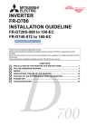
MITSUBISHI ELECTRIC
GOT1000
GT1020/GT1030 to FX Connection
Start-up Guide
Art.-Nr.: xxxxxx
20 102008
Version A
MITSUBISHI ELECTRIC
INDUSTRIAL AUTOMATION
About this Manual
The texts, illustrations, diagrams and examples in this manual are only intended as aids to help
explain the functioning, operation, use and programming of the GOT1000 terminals in combination with an FX PLC.
If you have any questions regarding the installation and operation of the hardware described in
this manual, please do not hesitate to contact your sales office or one of your Mitsubishi distribution partners.
b
CAUTION:
Do not attempt to install, operate, maintain or inspect the grafical operator terminal or
the PLC until you have read through the correrponding instruction manual carefully
and can use the equipment correctly. Do not use the PLC until you have a full
knowledge of the equipment, safety information and instructions.
You can also obtain information and answers to frequently asked questions from our Mitsubishi
website under www.mitsubishi-automation.com.
No part of this manual may be reproduced, copied, stored in any kind of information retrieval system or distributed without the prior express written consent of MITSUBISHI ELECTRIC.
MITSUBISHI ELECTRIC reserves the right to change the specifications of its products and/or
the contents of this manual at any time and without prior notice.
© Version A October 2008
Manual References:
Refer to the following manuals for more detailed explanations. For any further questions, please
contact your local Mitsubishi Product Provider.
● GT10 User’s Manual (JY997D24701)
● GT10 General Description (JY997D22901)
● RS-232 / USB Conversion Adapter User’s Manual (JY997D23401)
● GOT1000 Series Connection Manual 1/3 (SH(NA)-080532ENG)
b
CAUTION:
This Start-up Guide includes a brief summary of the main specifications of the
GOT1000 graphic operation terminals and the FX series of PLC, which should be
sufficient to enable experienced users to install and configure the units. For further
information on the operation terminals and the inverters please refer to the above
mentioned manuals.
Please observe also the safety precautions given in the manuals mentioned above.
GOT1000
I
II
Table of Contents
Table of Contents
1
Overview . . . . . . . . . . . . . . . . . . . . . . . . . . . . . . . . . . . . . . . . . . . . . . . . . . . . . . . . . . . .1
2
Hardware Introduction. . . . . . . . . . . . . . . . . . . . . . . . . . . . . . . . . . . . . . . . . . . . . . . . .1
3
Cabling . . . . . . . . . . . . . . . . . . . . . . . . . . . . . . . . . . . . . . . . . . . . . . . . . . . . . . . . . . . . .2
3.1
GOT Terminal . . . . . . . . . . . . . . . . . . . . . . . . . . . . . . . . . . . . . . . . . . . . . . . . . .3
3.2
Programming Cables . . . . . . . . . . . . . . . . . . . . . . . . . . . . . . . . . . . . . . . . . . . .4
3.3
Example Connection Diagram . . . . . . . . . . . . . . . . . . . . . . . . . . . . . . . . . . . . .4
4
Firmware Updates . . . . . . . . . . . . . . . . . . . . . . . . . . . . . . . . . . . . . . . . . . . . . . . . . . . .5
5
Confirm Communication . . . . . . . . . . . . . . . . . . . . . . . . . . . . . . . . . . . . . . . . . . . . . . .6
GOT1000
III
Overview
1
Start-up Guide
Overview
This document provides a simple guide and reference for setting up the GT1020 or GT1030
Graphic Operation Terminal (GOT) hardware and firmware for use with an FX Series PLC.
2
Hardware Introduction
The GT1020 and GT1030 are monochrome, 3-color backlight, two communication channel
GOT1000 Series touch panel interfaces, and consist of the following models:
Model
Size
Backlight Colors
-LBD
Green/Orange/Red
-LBD2
-LBDW
GT1020
-LBDW2
3.7”
160 x 64 dot
White/Pink/Red
-LBL
Green/Orange/Red
-LBLW
White/Pink/Red
-LBD
Comm. IF
Power
RS-422
RS-232C
RS-422
24 V DC
RS-232C
RS-422
5 V DC
RS-422
Green/Orange/Red
-LBD2
GT1030
-LBDW
RS-232C
4.5”
288 x 96 dot
24 V DC
RS-422
White/Pink/Red
-LBDW2
Tab. 1:
RS-232C
Specifications of the operator terminals
For new GT1020 and GT1030 units,
included in the box should be the following
items:
앫 (A) GT1020/GT1030
앫 (B) 1 PLC Communication Connector
앫 (C) 1 rubber Panel Mounting Packing
앫 (D) 4 Panel Mounting Brackets
A
B
C
D
GOT1000
1
Start-up Guide
3
Cabling
Cabling
Power
All GT1020/GT1030 GOTs except for the
GT1020-LBL and GT1020-LBLW (5V DC
versions) require an external 24V DC power
supply to be connected to the Power Terminal on the back of the GOT. The 5V DC versions are powered through the communication cables, described below.
5V DC version GT1020 GOTs
The GT1020-LBL and GT1020-LBLW are the only two 5V DC GOTs in the GOT1000 lineup.
They are powered directly from the communication cable, and can only be connected with an FX
Series PLC. Other PLCs and connectable products will not provide the necessary 5V DC power.
The power terminals have been removed from the 5V DC versions.
Communication
For the GT1020/GT1030 to communicate with an FX Series PLC, a dedicated communication
cable is required to connect the provided PLC Communication Connector with the Programming
Port (RS-422 8-pin Mini-DIN) or other communication channel of the FX (RS-422 8-pin Mini-DIN
or RS-232C 9-pin D-sub). The cable names and length and specific wiring for each case are illustrated below:
Cable Name
Length
햲
1m
햲
GT10-C10R4-8P
GT10-C30R4-8P
3m
GT10-C100R4-8P
10m
GT10-C200R4-8P
20m
GT10-C300R4-8P
30m
Tab. 2:
Applicable GOTs
FX Comm. Equipment
GT1020-LBD
GT1020-LBDW
GT1030-LBD
GT1030-LBDW
Programming Port
FX3U-422-BD
FX2N-422-BD
FX1N-422-BD
Connection to an RS-422 FX communication channel
햲 Only the GT10-C10R4-8P and GT10-C30R4-8P apply to the GT1020-LBL and GT1020-LBLW GOTs
(5V DC versions).
GOT Side (terminal block)
Signal name
24V products
CSA
CSB
2
PLC side
Cable connection
United wire color
of GT10-C첸첸첸R4-8P
Pin layout
5V products
SDA
Brown
SDB
Red
RDA
Orange
RDB
Yellow
SG
Green
RSA
Black
RSB
White
INPUT 5VDC +
MINI-DIN 8 Pin: male
Cabling
Start-up Guide
Cable Name
All RS-232C GT1020/GT1030-to-FX
connection cables must be made by
the user as described below.
Tab. 3:
Applicable GOTs
FX Comm. Equipment
GT1020-LBD2
GT1020-LBDW2
GT1030-LBD2
GT1030-LBDW2
FX3U-232-BD
FX3U-232ADP(-MB)햳
FX2N-232-BD
FX2NC-232ADP햳
FX1N-232-BD
Connection to an RS-232C FX communication channel
햳 Special Adapters require an additional FX**-CNV-BD or, for the FX
3U only, a Communication Expansion Board.
GOT Side
(terminal block)
3.1
Cable connection
Signal name
PIN No.
SD
1
RD
2
ER
3
DR
4
SG
5
RS
6
CS
7
NC
8
NC
9
Pin layout
D-SUB 9 pins: female
GOT Terminal
For all screw terminals on the GT1020/
GT1030, use a small flathead screwdriver to
secure the wires within the PLC Communication Connector (recommended blade size
and tightening torque: 0.4 x 2.5 mm and
0.22 to 0.25 N•m).
Fig. 1:
GOT1000
FX PLC side
(Dsub 9 pin)
Select a screwdriver
with a straight tip.
Terminal points in detail
3
Start-up Guide
3.2
Cabling
Programming Cables
The GT1020 and GT1030 come pre-installed with an OS and FX communication driver, but without any project data. To download a project
from a PC running GT Designer2 to the GOT, a programming cable is
required that connects to the RS-232C 6-pin Mini-DIN port on the back
of the GOT. It is recommended to use a shielded USB A-type to MiniB type cable with a ferrite core paired with the GT10-RS2TUSB-5S, but
any RS-232C programming cable for the Q-Series will also work fine. A
diagram of both is shown below.
QC30R2 (RS-232C)
PC
GOT
or
USB + GT10-RS2TUSB-5S
Fig. 2:
NOTE
3.3
Connection diagram
Note that using the GT10-RS2TUSB-5S will require a virtual USB COM port driver to be
installed on the PC. The COM port number can be automatically or manually assigned so
that it does not overlap with the existing COM port numbers assigned on that PC. When
using a Q-Series programming cable, the COM port number already assigned to the RS232C interface of the PC will have to be checked.
Example Connection Diagram
The GOT in the following figure is supplied from the 24V DC service power supply of the FX3U base
unit.
Power supply
Programming
GT10-RS2TUSB-5S + USB
FX3U422-BD
FX3U-16MR-ES/UL
GT10-C100R4-8P
Data
Fig. 3:
4
GT1020-LBD
(Back)
Example for the connection of a GT1020 to a FX3U PLC
PC
Firmware Updates
4
Start-up Guide
Firmware Updates
(Version 2.73 or later)
To make sure the GT1020/GT1030 GOT is
able to use the latest functions and features,
it is the responsibility of the user to check and
update the firmware (Standard monitor OS)
of the GOT.
Launch the latest copy of GT Designer2 and
start a new project for the corresponding
GOT model (GT1020 or GT1030) with the
“MELSEC-FX” Controller Type. Select “Yes”
to set the Communication Setting and make
sure the Standard I/F-1 CH No. is set to 1 before selecting “OK”. The “Screen Property”
window that pops up for making a new screen
can be either canceled or accepted for the following steps.
Go to the “Communication” menu and select
“To/From GOT” to bring up the “Communicate with GOT” window. Go to the “Communication configuration” tab and select “RS232”
and the corresponding “Port No.” that connects the PC to the GOT. With the GOT power ON, use the “Test” button to verify that
the PC and GOT can communicate properly
then turn the GOT power OFF.
To access the OS installation mode of the
GT1020/GT1030, switch the GOT power
from OFF to ON, while holding the bottom
right corner of the touch screen (in Horizontal
layout), illustrated to the right.
While the “Please install the OS” screen is
displayed, go to the “OS Install -> GOT” tab in
the “Communicate with GOT” window of GT
Designer2 and select “Standard monitor OS”
from the data selection tree. Use the “Install”
button to initiate the data transfer and update
the firmware. Once the firmware update has
been completed the GOT will automatically
reboot and all features will be up to date. Note
that new project data will need to be downloaded to the GOT.
GOT1000
5
Start-up Guide
5
Confirm Communication
Confirm Communication
The communication monitoring is a function that checks whether the GOT can communicate
with the PLC. If no error is shown, communication has been set up correctly.
6
MITSUBISHI ELECTRIC
HEADQUARTERS
EUROPEAN REPRESENTATIVES
EUROPEAN REPRESENTATIVES
MITSUBISHI ELECTRIC EUROPE B.V.
EUROPE
German Branch
Gothaer Straße 8
D-40880 Ratingen
Phone: +49 (0)2102 / 486-0
Fax: +49 (0)2102 / 486-1120
MITSUBISHI ELECTRIC EUROPE B.V. CZECH REPUBLIC
Czech Branch
Radlicka 714/113 a
CZ-158 00 Praha 5
Phone: +420 251 551 470
Fax: +420-251-551-471
MITSUBISHI ELECTRIC EUROPE B.V.
FRANCE
French Branch
25, Boulevard des Bouvets
F-92741 Nanterre Cedex
Phone:+33 (0)1 / 55 68 55 68
Fax: +33 (0)1 / 55 68 57 57
MITSUBISHI ELECTRIC EUROPE B.V.
IRELAND
Irish Branch
Westgate Business Park, Ballymount
IRL-Dublin 24
Phone: +353 (0)1 4198800
Fax: +353 (0)1 4198890
MITSUBISHI ELECTRIC EUROPE B.V.
ITALY
Italian Branch
Viale Colleoni 7
I-20041 Agrate Brianza (MI)
Phone: +39 039 / 60 53 1
Fax: +39 039 / 60 53 312
MITSUBISHI ELECTRIC EUROPE B.V.
SPAIN
Spanish Branch
Carretera de Rubí 76-80
E-08190 Sant Cugat del Vallés (Barcelona)
Phone: 902 131121 // +34 935653131
Fax: +34 935891579
MITSUBISHI ELECTRIC EUROPE B.V.
UK
UK Branch
Travellers Lane
UK-Hatfield, Herts. AL10 8XB
Phone: +44 (0)1707 / 27 61 00
Fax: +44 (0)1707 / 27 86 95
MITSUBISHI ELECTRIC CORPORATION
JAPAN
Office Tower “Z” 14 F
8-12,1 chome, Harumi Chuo-Ku
Tokyo 104-6212
Phone: +81 3 622 160 60
Fax: +81 3 622 160 75
MITSUBISHI ELECTRIC AUTOMATION, Inc.
USA
500 Corporate Woods Parkway
Vernon Hills, IL 60061
Phone: +1 847 478 21 00
Fax: +1 847 478 22 53
GEVA
AUSTRIA
Wiener Straße 89
AT-2500 Baden
Phone: +43 (0)2252 / 85 55 20
Fax: +43 (0)2252 / 488 60
TEHNIKON
BELARUS
Oktyabrskaya 16/5, Off. 703-711
BY-220030 Minsk
Phone: +375 (0)17 / 210 46 26
Fax: +375 (0)17 / 210 46 26
Koning & Hartman b.v.
BELGIUM
Woluwelaan 31
BE-1800 Vilvoorde
Phone: +32 (0)2 / 257 02 40
Fax: +32 (0)2 / 257 02 49
AKHNATON
BULGARIA
4 Andrej Ljapchev Blvd. Pb 21
BG-1756 Sofia
Phone: +359 (0)2 / 817 6004
Fax: +359 (0)2 / 97 44 06 1
INEA CR d.o.o.
CROATIA
Losinjska 4 a
HR-10000 Zagreb
Phone: +385 (0)1 / 36 940 - 01/ -02/ -03
Fax: +385 (0)1 / 36 940 - 03
AutoCont C.S., s.r.o.
CZECH REPUBLIC
Technologicka 374/6
CZ-708 00 Ostrava Pustkovec
Phone: +420 (0)59 / 5691 150
Fax: +420 (0)59 / 5691 199
B:TECH, a.s.
CZECH REPUBLIC
U Borove 69
CZ-58001 Havlickuv Brod
Phone: +420 (0)569 777 777
Fax: +420 (0)569-777 778
Beijer Electronics A/S
DENMARK
Lykkegårdsvej 17, 1.
DK-4000 Roskilde
Phone: +45 (0)46/ 75 76 66
Fax: +45 (0)46 / 75 56 26
Beijer Electronics Eesti OÜ
ESTONIA
Pärnu mnt.160i
EE-11317 Tallinn
Phone: +372 (0)6 / 51 81 40
Fax: +372 (0)6 / 51 81 49
Beijer Electronics OY
FINLAND
Jaakonkatu 2
FIN-01620 Vantaa
Phone: +358 (0)207 / 463 500
Fax: +358 (0)207 / 463 501
UTECO A.B.E.E.
GREECE
5, Mavrogenous Str.
GR-18542 Piraeus
Phone: +30 211 / 1206 900
Fax: +30 211 / 1206 999
MELTRADE Ltd.
HUNGARY
Fertő utca 14.
HU-1107 Budapest
Phone: +36 (0)1 / 431-9726
Fax: +36 (0)1 / 431-9727
Beijer Electronics SIA
LATVIA
Vestienas iela 2
LV-1035 Riga
Phone: +371 (0)784 / 2280
Fax: +371 (0)784 / 2281
Beijer Electronics UAB
LITHUANIA
Savanoriu Pr. 187
LT-02300 Vilnius
Phone: +370 (0)5 / 232 3101
Fax: +370 (0)5 / 232 2980
INTEHSIS srl
MOLDOVA
bld. Traian 23/1
MD-2060 Kishinev
Phone: +373 (0)22 / 66 4242
Fax: +373 (0)22 / 66 4280
Koning & Hartman b.v.
NETHERLANDS
Haarlerbergweg 21-23
NL-1101 CH Amsterdam
Phone: +31 (0)20 / 587 76 00
Fax: +31 (0)20 / 587 76 05
Beijer Electronics AS
NORWAY
Postboks 487
NO-3002 Drammen
Phone: +47 (0)32 / 24 30 00
Fax: +47 (0)32 / 84 85 77
MPL Technology Sp. z o.o.
POLAND
Ul. Krakowska 50
PL-32-083 Balice
Phone: +48 (0)12 / 630 47 00
Fax: +48 (0)12 / 630 47 01
Sirius Trading & Services srl
ROMANIA
Aleea Lacul Morii Nr. 3
RO-060841 Bucuresti, Sector 6
Phone: +40 (0)21 / 430 40 06
Fax: +40 (0)21 / 430 40 02
Craft Con. & Engineering d.o.o.
SERBIA
Bulevar Svetog Cara Konstantina 80-86
SER-18106 Nis
Phone: +381 (0)18 / 292-24-4/5 , 523 962
Fax: +381 (0)18 / 292-24-4/5 , 523 962
INEA SR d.o.o.
SERBIA
Karadjordjeva 12/260
SER-113000 Smederevo
Phone: +381 (0)26 / 617 163
Fax: +381 (0)26 / 617 163
AutoCont Control, s.r.o.
SLOVAKIA
Radlinského 47
SK-02601 Dolny Kubin
Phone: +421 (0)43 / 5868210
Fax: +421 (0)43 / 5868210
CS MTrade Slovensko, s.r.o.
SLOVAKIA
Vajanskeho 58
SK-92101 Piestany
Phone: +421 (0)33 / 7742 760
Fax: +421 (0)33 / 7735 144
INEA d.o.o.
SLOVENIA
Stegne 11
SI-1000 Ljubljana
Phone: +386 (0)1 / 513 8100
Fax: +386 (0)1 / 513 8170
Beijer Electronics Automation AB
SWEDEN
Box 426
SE-20124 Malmö
Phone: +46 (0)40 / 35 86 00
Fax: +46 (0)40 / 35 86 02
Econotec AG
SWITZERLAND
Hinterdorfstr. 12
CH-8309 Nürensdorf
Phone: +41 (0)44 / 838 48 11
Fax: +41 (0)44 / 838 48 12
GTS
TURKEY
Darulaceze Cad. No. 43 KAT. 2
TR-34384 Okmeydani-Istanbul
Phone: +90 (0)212 / 320 1640
Fax: +90 (0)212 / 320 1649
CSC Automation Ltd.
UKRAINE
15, M. Raskova St., Fl. 10, Office 1010
UA-02002 Kiev
Phone: +380 (0)44 / 494 33 55
Fax: +380 (0)44 / 494-33-66
MITSUBISHI
ELECTRIC
FACTORY AUTOMATION
EURASIAN REPRESENTATIVES
Kazpromautomatics Ltd.
Mustafina Str. 7/2
KAZ-470046 Karaganda
Phone: +7 7212 / 50 11 50
Fax: +7 7212 / 50 11 50
CONSYS
Promyshlennaya st. 42
RU-198099 St. Petersburg
Phone: +7 812 / 325 36 53
Fax: +7 812 / 325 36 53
Drive Technique STC
1-st Magistralny tupik, 10, bld 1
RU-123290 Moscow
Phone: +7 495 / 786-21 00
Fax: +7 495 / 786-21 01
ELECTROTECHNICAL SYSTEMS
Derbenevskaya st. 11A, Office 69
RU-115114 Moscow
Phone: +7 495 / 744 55 54
Fax: +7 495 / 744 55 54
ELEKTROSTILY
Rubzowskaja nab. 4-3, No. 8
RU-105082 Moscow
Phone: +7 495 / 545 3419
Fax: +7 495 / 545 3419
RPS-AUTOMATIKA
Budennovsky 97, Office 311
RU-344007 Rostov on Don
Phone: +7 8632 / 22 63 72
Fax: +7 8632 / 219 45 51
KAZAKHSTAN
RUSSIA
RUSSIA
RUSSIA
RUSSIA
RUSSIA
MIDDLE EAST REPRESENTATIVE
SHERF Motion Techn. Ltd.
Rehov Hamerkava 19
IL-58851 Holon
Phone: +972 (0)3 / 559 54 62
Fax: +972 (0)3 / 556 01 82
ISRAEL
AFRICAN REPRESENTATIVE
CBI Ltd.
Private Bag 2016
ZA-1600 Isando
Phone: + 27 (0)11 / 928 2000
Fax: + 27 (0)11 / 392 2354
SOUTH AFRICA
Mitsubishi Electric Europe B.V. /// FA - European Business Group /// Gothaer Straße 8 /// D-40880 Ratingen /// Germany
Tel.: +49(0)2102-4860 /// Fax: +49(0)2102-4861120 /// [email protected] /// www.mitsubishi-automation.com