1
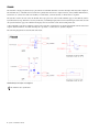
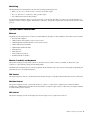
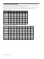
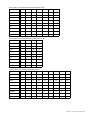
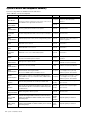
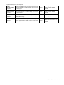
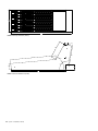
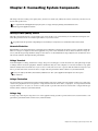
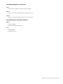
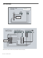
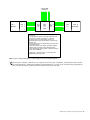
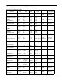
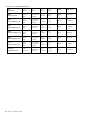
System 5 Installation Guide Legal Notices This guide is copyrighted ©2011 by Avid Technology, Inc., (hereafter “Avid”), with all rights reserved. Under copyright laws, this guide may not be duplicated in whole or in part without the written consent of Avid. 003, 96 I/O, 96i I/O, 192 Digital I/O, 192 I/O, 888|24 I/O, 882|20 I/O, 1622 I/O, 24-Bit ADAT Bridge I/O, AudioSuite, Avid, Avid DNA, Avid Mojo, Avid Unity, Avid Unity ISIS, Avid Xpress, AVoption, Axiom, Beat Detective, Bomb Factory, Bruno, C|24, Command|8, Control|24, D-Command, D-Control, D-Fi, D-fx, D-Show, D-Verb, DAE, Digi 002, DigiBase, DigiDelivery, Digidesign, Digidesign Audio Engine, Digidesign Intelligent Noise Reduction, Digidesign TDM Bus, DigiDrive, DigiRack, DigiTest, DigiTranslator, DINR, DV Toolkit, EditPack, Eleven, HD Core, HD I/O, HD MADI, HD OMNI, HD Process, Hybrid, Impact, Interplay, LoFi, M-Audio, MachineControl, Maxim, Mbox, MediaComposer, MIDI I/O, MIX, MultiShell, Nitris, OMF, OMF Interchange, PRE, ProControl, Pro Tools, Pro Tools|HD, QuickPunch, Recti-Fi, Reel Tape, Reso, Reverb One, ReVibe, RTAS, Sibelius, Smack!, SoundReplacer, Sound Designer II, Strike, Structure, SYNC HD, SYNC I/O, Synchronic, TL Aggro, TL AutoPan, TL Drum Rehab, TL Everyphase, TL Fauxlder, TL In Tune, TL MasterMeter, TL Metro, TL Space, TL Utilities, Transfuser, Trillium Lane Labs, Vari-Fi Velvet, X-Form, and XMON are trademarks or registered trademarks of Avid Technology, Inc. Xpand! is Registered in the U.S. Patent and Trademark Office. All other trademarks are the property of their respective owners. Product features, specifications, system requirements, and availability are subject to change without notice. Guide Part Number 9329-65128-00 REV A 08/11 Documentation Feedback We are always looking for ways to improve our documentation. If you have comments, corrections, or suggestions regarding our documentation, email us at [email protected]. Contents Chapter 1. Introduction . . . . . . . . . . . . . . . . . . . . . . . . . . . . . . . . . . . . . . . . . . . . . . . . . . . . . . . . . . . . . . . . . . . . . . . . . . . 5 System Requirements and Compatibility . . . . . . . . . . . . . . . . . . . . . . . . . . . . . . . . . . . . . . . . . . . . . . . . . . . . . . . . . . . . . 5 About This Guide. . . . . . . . . . . . . . . . . . . . . . . . . . . . . . . . . . . . . . . . . . . . . . . . . . . . . . . . . . . . . . . . . . . . . . . . . . . . . . 5 About www.avid.com . . . . . . . . . . . . . . . . . . . . . . . . . . . . . . . . . . . . . . . . . . . . . . . . . . . . . . . . . . . . . . . . . . . . . . . . . . . 6 Chapter 2. System 5 Overview . . . . . . . . . . . . . . . . . . . . . . . . . . . . . . . . . . . . . . . . . . . . . . . . . . . . . . . . . . . . . . . . . . . . . 7 Theory of Operation . . . . . . . . . . . . . . . . . . . . . . . . . . . . . . . . . . . . . . . . . . . . . . . . . . . . . . . . . . . . . . . . . . . . . . . . . . . . 7 I/O Solutions . . . . . . . . . . . . . . . . . . . . . . . . . . . . . . . . . . . . . . . . . . . . . . . . . . . . . . . . . . . . . . . . . . . . . . . . . . . . . . . 11 System Control Connections. . . . . . . . . . . . . . . . . . . . . . . . . . . . . . . . . . . . . . . . . . . . . . . . . . . . . . . . . . . . . . . . . . . . . 13 Estimating System Requirements . . . . . . . . . . . . . . . . . . . . . . . . . . . . . . . . . . . . . . . . . . . . . . . . . . . . . . . . . . . . . . . . . 14 System 5 Module and Component Summary . . . . . . . . . . . . . . . . . . . . . . . . . . . . . . . . . . . . . . . . . . . . . . . . . . . . . . . . . 18 Chapter 3. System 5 Console . . . . . . . . . . . . . . . . . . . . . . . . . . . . . . . . . . . . . . . . . . . . . . . . . . . . . . . . . . . . . . . . . . . . . 21 Console Component Connections . . . . . . . . . . . . . . . . . . . . . . . . . . . . . . . . . . . . . . . . . . . . . . . . . . . . . . . . . . . . . . . . . 21 Console Dimensions . . . . . . . . . . . . . . . . . . . . . . . . . . . . . . . . . . . . . . . . . . . . . . . . . . . . . . . . . . . . . . . . . . . . . . . . . . 23 Chapter 4. Connecting System Components . . . . . . . . . . . . . . . . . . . . . . . . . . . . . . . . . . . . . . . . . . . . . . . . . . . . . . . 27 Facility Power Quality Issues . . . . . . . . . . . . . . . . . . . . . . . . . . . . . . . . . . . . . . . . . . . . . . . . . . . . . . . . . . . . . . . . . . . . 27 Typical Room and Equipment Layout . . . . . . . . . . . . . . . . . . . . . . . . . . . . . . . . . . . . . . . . . . . . . . . . . . . . . . . . . . . . . . 28 Audio Connections . . . . . . . . . . . . . . . . . . . . . . . . . . . . . . . . . . . . . . . . . . . . . . . . . . . . . . . . . . . . . . . . . . . . . . . . . . . 30 Synchronization Connections . . . . . . . . . . . . . . . . . . . . . . . . . . . . . . . . . . . . . . . . . . . . . . . . . . . . . . . . . . . . . . . . . . . . 31 MADI Connections . . . . . . . . . . . . . . . . . . . . . . . . . . . . . . . . . . . . . . . . . . . . . . . . . . . . . . . . . . . . . . . . . . . . . . . . . . . . 34 Control Connections . . . . . . . . . . . . . . . . . . . . . . . . . . . . . . . . . . . . . . . . . . . . . . . . . . . . . . . . . . . . . . . . . . . . . . . . . . 36 System 5 Console and Module Specifications . . . . . . . . . . . . . . . . . . . . . . . . . . . . . . . . . . . . . . . . . . . . . . . . . . . . . . . . 37 Appendix A. Compliance Information . . . . . . . . . . . . . . . . . . . . . . . . . . . . . . . . . . . . . . . . . . . . . . . . . . . . . . . . . . . . . . 39 Environmental Compliance. . . . . . . . . . . . . . . . . . . . . . . . . . . . . . . . . . . . . . . . . . . . . . . . . . . . . . . . . . . . . . . . . . . . . . 39 EMC (Electromagnetic Compliance). . . . . . . . . . . . . . . . . . . . . . . . . . . . . . . . . . . . . . . . . . . . . . . . . . . . . . . . . . . . . . . . 39 Safety Compliance . . . . . . . . . . . . . . . . . . . . . . . . . . . . . . . . . . . . . . . . . . . . . . . . . . . . . . . . . . . . . . . . . . . . . . . . . . . 40 Contents iii iv System 5 Installation Guide Chapter 1: Introduction System 5 is an elaborately featured digital audio mixing system that can be configured to meet the requirements of large-scale film production, on-air broadcast, post-production, and music. System 5 features and options include: • Scalable control surface with application-specific controls, such as dual joysticks with a film monitor panel • Scalable DSP mix engine • Flexible I/O system • Integrated MADI router • Serial machine control interface • GPIO System Requirements and Compatibility Avid can only assure compatibility and provide support for hardware and software it has tested and approved. For complete system requirements and a list of qualified computers, operating systems, hard drives, and third-party devices, visit: www.avid.com/compatibility About This Guide This guide provides a basic overview of System 5 features and functionality. For complete instructions on connecting and configuring your system, see the System 5 Installation Guide. Conventions Used in This Guide All of our guides use the following conventions to indicate menu choices and key commands: : Convention Action File > Save Choose Save from the File menu Control+N Hold down the Control key and press the N key Control-click Hold down the Control key and click the mouse button Right-click Click with the right mouse button The names of Commands, Options, and Settings that appear on-screen are in a different font. The following symbols are used to highlight important information: User Tips are helpful hints for getting the most from your system. Important Notices include information that could affect your data or the performance of your system. Shortcuts show you useful keyboard or mouse shortcuts. Cross References point to related sections in this guide and other Avid guides. Chapter 1: Introduction 5 About www.avid.com The Avid website (www.avid.com) is your best online source for information to help you get the most out of your system. The following are just a few of the services and features available. Product Registration Register your purchase online. Support and Downloads Contact Avid Customer Success (technical support); download software updates and the latest online manuals; browse the Compatibility documents for system requirements; search the online Knowledge Base or join the worldwide Avid user community on the User Conference. Training and Education Study on your own using courses available online or find out how you can learn in a classroom setting at a certified Avid training center. Products and Developers Learn about Avid products; download demo software or learn about our Development Partners and their plug-ins, applications, and hardware. News and Events Get the latest news from Avid or sign up for a demo. 6 System 5 Installation Guide Chapter 2: System 5 Overview This chapter provides a basic overview of the System 5 theory of operation, I/O solutions, and system requirements. Chapter 3, “System 5 Console” presents the console in detail, including physical and environmental specifications. Chapter 4, “Connecting System Components” illustrates how to interconnect system modules and components. Theory of Operation The primary components of System 5 are the DF66 or DF70 SuperCore mix engine, control surface modules, the SC264 System Computer, and the CO600 MADI Changeover Switch (used in broadcast redundancy configurations). These devices, along with TCP/IP-controlled devices such as the Modular I/O Remote Preamps, communicate via a 100 Base-T star network. The SC264 contains the GPIO and serial machine control interface. Secondary peripheral devices, such as the ML530 Mic-Line Interface and the MC524 Monitor Interface, connect to the SC264 System Computer and communicate via the System 5 TCC serial protocol. All Avid I/O devices interface via MADI and connect directly to the DF66 or DF70 SuperCore, or to the CO600 MADI Changeover Switch. Digital Signal Processing The DF66 or DF70 SuperCore performs all System 5 audio processing and routing (Dynamics, EQ, mix busses, aux sends, and monitor busses). The DF66 can be fitted with up to six SP663 DSP Line cards, each of which provides four MADI I/Os. For systems that demand more DSP, the DF70 has eight cards that supports up to 454 channels at 48 kHz or 222 channels at 96 kHz. The actual DSP is allocated using factory-supplied Mixer Model files that provide different numbers of busses and channels. SuperCores with six or more SP663 Line Cards require Avantech modules with 1 GB RAM. The number of SP663 Line cards required in a system depends on the number of logical channels desired: a mono input uses one logical channel, a stereo input uses two, and a 7.1 input uses eight. The following devices can be used for non-redundant DSP configurations: • SC264D (1–2 cards) • SC264 + DF66 (1–6 cards) • SC264 + DF70 (8 cards) In broadcast redundancy configurations, two identical DF66s operate in parallel, one as primary and the other as backup. Each connects to the CO600 MADI Changeover Switch, which monitors the performance of both. If the primary DF66 fails, the backup is automatically placed online. The following devices can be used for redundant DSP configurations: • SC264D + DF66 + CO600 (1–2 cards) • SC264 + DF66x2 + CO600 (1–6 cards) All DSP card versions must run the most current firmware. See instructions with the update software. Chapter 2: System 5 Overview 7 TT002B The TT002B is a single-port, RS422 (Sony 9-pin) USB device and MMC machine controller that ships with all System Computers. The TT002B locks to a machine and reads LTC more quickly than the devices it replaced (TT002, TT007, MOTU Midi Interface, and GP132). To control more than one machine, a Sound Master, Colin Broad RM6, or similar device is required. The System 5 software can auto-sense the TT002B. The setup options are done from the Machines page on the CM401T, and the System Preferences Page. The timecode source, frame rate, track arming length, and fast forward/rewind speeds can all be set from the System Preferences page. The CM401T TFT displays the selected frame count and incoming frame rate. A TT003 machine controller is available for dual-operator System 5 configurations. It is physically different from the TT002 and requires different firmware. An additional USB port is provided to connect the two System Computers. The following diagram shows the TT002B’s GPI circuit. TT002B GPI input and output circuit diagrams The TT002 is not a synchronizer. 8 System 5 Installation Guide External Internal 37 way Female D- board header Type 1 1 20 2 2 3 21 4 3 5 22 6 4 7 23 8 5 9 24 10 6 11 25 12 7 13 26 14 8 15 27 16 9 17 28 18 10 19 29 20 11 21 30 22 12 23 31 24 13 25 32 26 14 27 33 28 15 29 34 30 16 31 35 32 17 33 36 34 18 35 37 36 19 37 GPI 1 GPO 1 GPI 2 GPO 2 GPI 3 GPO 3 GPI 4 GPO 4 GPI 5 GPO 5 GPI 6 GPO 6 GPI 7 GPO 7 GPI 8 GPO 8 GPI 9 GPO 9 GPI 10 GPO 10 GPI 11 GPO 11 GPI 12 GPO 12 GPI 13 GPO 13 GPI 14 GPO 14 GPI 15 GPO 15 GPI 16 GPO 16 GND(for GPI1~16) COM1 (for GPO1~4) COM2 (for GPO5~8) COM3 (for GPO9~12) COM4 (for GPO13~16) External Internal 37 way Female D- board header Type 1 1 20 2 2 3 21 4 3 5 22 6 4 7 23 8 5 9 24 10 6 11 25 12 7 13 26 14 8 15 27 16 9 17 28 18 10 19 29 20 11 21 30 22 12 23 31 24 13 25 32 26 14 27 33 28 15 29 34 30 16 31 35 32 17 33 36 34 18 35 37 36 19 37 GPI 17 GPO 17 GPI 18 GPO 18 GPI 19 GPO 19 GPI 20 GPO 20 GPI 21 GPO 21 GPI 22 GPO 22 GPI 23 GPO 23 GPI 24 GPO 24 GPI 25 GPO 25 GPI 26 GPO 26 GPI 27 GPO 27 GPI 28 GPO 28 GPI 29 GPO 29 GPI 30 GPO 30 GPI 31 GPO 31 GPI 32 GPO 32 GND(for GPI17~32) COM1 (for GPO17~20) COM2 (for GPO21~24) COM3 (for GPO25~28) COM4 (for GPO29~32) TT002B GPI input and output wiring chart Chapter 2: System 5 Overview 9 Control Surface Each control surface must include one CM401T Master Module and at least one CM408T Eight-Fader Module. The System 5 control surface modules are listed in the table below. Depending on the system configuration, the surface modules may have redundant PSUs. System 5 Control Surface Modules CM401T Master control module with configuration interface CM402T Expanded channel module with eight faders CM403 Dual joystick and film monitor panel CM408T Eight-fader module CM409F* Blank section, same size as the CM408T CM409H* Half-width blank section CM409HTP Half-width section with a trackball panner CM411 VGA input module with optional dual joysticks Facilities often install a larger console frame than is required for the initial surface module configuration. This can support future expansion or fulfill physical requirements for console access. Blank sections such as the CM409F and CM409H can fill otherwise empty spaces in the frame. Sources A System 5 fader can control one source at a time. Each source may be assigned a variety of formats, from mono to 7.1, and requires one or more logical channels. For example, a mono source requires one channel, a stereo source requires two, and a 7.1-channel source requires eight. This means that a fader assigned to a 7.1-channel source is controlling eight logical channels simultaneously. Physical Faders Each CM408T module has eight fader strips. Two sources in any format can be assigned to a fader strip, but only one can be controlled at a time. The fader strip’s Swap button switches between the two sources: When the Swap button is lit, the fader controls the Swap layer, otherwise it controls the Main layer. Layouts Source assignments to console faders can be saved using a Layout, which can map the entire console or just a selected number of faders. Layouts can be named, stored, and recalled to instantly remap the console surface. Recalling a Layout that does not include all faders remaps only those in the Layout. Consider two Layouts using a console with one CM408T with eight physical faders: • Layout 1 could recall 16 stereo sources assigned to the faders (eight Main, eight Swap), resulting in 32 logical channels. • Layout 2 could recall 16 5.1-channel sources assigned to the faders (eight Main, eight Swap), resulting in 96 logical channels. System Configuration The SC264 System Computer runs the eMix software, provides the primary console configuration interface, and performs file management functions. The computer also houses the TCC serial interface for monitor control, GPIO, and serial machine control. 10 System 5 Installation Guide DAW Control The SC264 uses the Avid EUCONTM high-speed network protocol to communicate with DAWs via a 100 Base-T network switch. Using EUCON, the console can simultaneously control up to five DAWs, including Pro Tools, Nuendo, Logic Pro, and Pyramix. EUCON network switch connection options include: • SC264D using virtual Hybrid Pilot (Fusion only) • PC254H Hybrid Pilot (S5, S5BP) SNMP SNMP monitoring is available in the DF66 and DF70 SuperCores and the CO600 MADI Changeover Switch. SNMP modules have battery back-up and an independent network connection. Power Most of the System 5 console components have dual power entry connectors for redundant power supplies. Avid recommends deriving power from two different sources to maximize failsafe capabilities. Connect one power supply to a UPS (Uninterruptible Power Supply) and the other to a clean technical power source. If a UPS is not used, the power supplies should be connected to separately protected, clean, technical power circuits. Synchronization Word Clock or AES Sync (DARS) may be used as the clock source required by many System 5 components, including the DF66/DF70 SuperCore, CO600 MADI Changeover Switch, and all MADI I/O. In addition, video sync is required for the serial machine control interface in the System Computer. Avid has tested several digital sync generators and distribution amplifiers and can supply these devices with the console. Contact Avid technical support for further information. The following guidelines produce reliable synchronization: • Word Clock/AES Sync is usually derived via a converter from the facility’s master video sync reference. Never employ multiple video sync-to-sample clock conversions in a single system. Separately derived sample clocks may not be in-phase. • Each distribution amplifier should be fed directly from the master clock source. This eliminates the timing differences between signal paths of different lengths. • Never loop synchronization signals through multiple MADI converters. This can lead to cumulative timing errors and loss of sync for downstream devices if that converter powers down. Illustrations in this guide show Word Clock, but AES Sync (DARS) may also be used. I/O Solutions Avid offers various I/O solutions, all employing MADI connections to the DF66/DF70/CO600. These include Avid stand-alone 2RU MADI converters as well as a flexible Modular I/O System (see page 12). It is also quite common to make MADI connections directly to DAWs and routers. Analog I/O The AM713 Analog-to-MADI Converter and MA703 MADI-to-Analog Converter are stand-alone 2RU units. The AM713 contains 26 analog inputs and one AES/SPDIF input with SRC (two channels). The MA703 contains 26 analog outputs and one AES/SPDIF output. Microphone The ML530 Mic-Line Interface contains 24 remote-controlled mic preamps. Audio outputs are fed to a dedicated AM713 Analog-to-MADI Converter for MADI connection to the DF66/DF70/CO600. The ML530 is controlled via the TCC serial protocol by the System Computer. Up to seven ML530s may be deployed in a system. Chapter 2: System 5 Overview 11 Digital I/O The DM714 AES-to-MADI Converter and MD704 MADI-to-AES Converter are stand-alone 2RU units. The DM714 contains 13 AES inputs (26 channels) with SRC, and two analog inputs. The MD704 contains 13 AES and two analog outputs. Units are available with 110- XLR or 75- BNC connections. Avid Modular I/O Avid Modular I/O System 5 configurations consist of one or more 3RU frames with redundant PSUs that can be fitted with a variety of I/O modules. All signals to the console are converted to and from MADI. Depending on the configuration, a maximum signal density of 64 inputs and 64 outputs can be achieved on a single MADI I/O. The Modular I/O system supports the following audio formats: remote-controlled preamp, line level analog, AES/EBU, and HD/SD embedder/de-embedder. Additional modules handle sync, MADI I/O, and remote-control interface. Refer to the Modular I/O Configuration Guide for complete details. The Modular I/O system includes the following modules: Digital • DD915 8ch AES I/O (110 DSub) 1 slot • DD916 8ch AES I/O (75 BNC) 2 slots Analog Line • AD920 4ch Analog Input (XLR) • DA921 4ch Analog Output (XLR) • AD922 4ch Analog Input (D-sub) • DA923 4ch Analog Output (D-sub) Microphone Preamp • AD914 4ch Mic Input (RJ-45) De-embedder The Modular I/O system can include a 16-channel de-embedder module that de-embeds audio from a video signal. • HD944 16ch HD De-embedder (no embedder function) Video In/Thru, 1 slot, supports SMPTE299M HD standard Dolby These Dolby encoders and decoders use one slot. See the Modular I/O Configuration Guide for details. • DE901 Dolby D/E Decoder • DE911 Dolby E Encoder • DE912 Dolby D/D+ Encoder Format Conversion The FC726 Format Converter is a bidirectional MADI converter, supplying 28 AES inputs (56 channels) with SRC and 28 AES outputs. I/O is divided into eight-channel banks to interface to multichannel devices, such as digital multitracks and DAWs. In addition to AES/EBU I/O, the FC726 supports direct connection to several third-party formats, including TDIF, SDIF-2, ADAT Optical, and MADI (via SRCs). AES/EBU outputs are always active even when using third-party formats. 12 System 5 Installation Guide Monitoring The MC524 Monitor-Comms Interface provides the following monitoring features: • Main (7.1), Alt 1 (5.1), and Alt 2 (stereo) control room speaker outputs • SLS (7.1), and Cues 1-3 (each stereo) studio speaker outputs • Two talkback and four listen mic preamps A dedicated MA703 MADI-to-Analog Converter feeds audio to the MC524. The MA703 is connected to the DF66 MADI out 1, which is reserved for monitor outputs. The MC524 is connected to the System Computer and controlled via the Avid TCC serial protocol. System Control Connections Ethernet All primary system components are connected via RJ-45 Ethernet through a 100 Base-T Ethernet switch. These devices include: • SC264 System Computer • CM401T Master Fader Module (console center section) • CM402T Expanded Channel Module (console center section) • CM403 Film and Joystick Panels • CM408T Eight-channel Modules • DF66 SuperCore • DF70 SuperCore • CO600 Changeover Switch • Modular I/O Remote modules Monitor, Trackball, and Keyboard The System Computer provides master control for the entire system. Connect a monitor, trackball, and keyboard to this computer to control mixing, routing, and file management. A KVM Extender is normally used to route these signals from the machine room to the control room through a single multi-pair cable built into the console Ethernet harness. TCC Control The System computer connects to the MC524 Monitor Interface and up to seven ML530 Mic-Line Interfaces via TCC connections. Machine Control The System Computer provides a 9-pin serial interface to connect to a serial device or synchronizer (Colin Broad RM6 or Soundmaster). A MIDI interface and timecode I/O are included on a separate 9-pin connector. A BNC video sync input is available for serial machine control reference. GPI Control The System Computer provides 32 GPI inputs and 32 GPI outputs on two 37-pin D-sub connectors. Chapter 2: System 5 Overview 13 Estimating System Requirements This section helps estimate your system’s installation requirements. Contact an Avid representative for an exact specification. Most of the studio details considered here are relevant to any digital mixing system. The Mixer Model’s relationship to the number of Line Cards is illustrated in the tables below. A Mixer Model consists of the attributes in a column. Note that the DF66 can have 1–6 Line Cards installed, while the DF70 always has eight. System 5B (Broadcast) at 48 kHz Cards 1 2 3 4 5 6 6 Channels 50 76 116 160 210 260 304 Mix 12 24 24 32 32 32 32 8 16 24 24 24 24 24 16 20 24 24 24 24 24 Bus Processors 0 8 12 16 16 16 0 Solo 2 2 2 2 2 2 2 Mix Minus 1 1 1 1 1 1 1 Externals 16 24 24 32 32 32 32 105 171 227 291 341 391 419 Group Aux Total Paths System 5 (Music), System 5BP (Broadcast-Post) at 48 kHz Cards 1 2 2 2 3 4 5 6 6 Channels 54 90 112 128 156 184 244 304 334 Mix 20 32 32 16 32 48 48 48 48 Group 8 8 8 24 8 8 8 8 8 Aux 8 16 16 2 16 24 24 24 24 Bus Processors 0 8 0 0 8 8 8 8 0 Solo 2 2 2 2 2 2 2 2 2 Mix Minus 0 0 0 0 0 0 0 0 0 Externals 16 24 24 6 24 32 32 32 32 108 180 194 178 246 306 366 426 448 Total Paths 14 System 5 Installation Guide System 5 (Music), System 5BP (Broadcast-Post) with DF70 at 48 kHz Cards 8 8 8 8 8 8 8 424 454 404 362 344 380 312 48 48 48 64 96 64 48 8 8 2 8 8 8 48 24 24 24 16 8 24 24 Bus Processors 8 0 48 64 48 24 48 Solo 2 2 2 2 2 2 2 Mix Minus 0 0 0 0 0 0 0 Externals 24 24 24 72 72 32 32 538 560 552 588 578 534 514 Channels Mix Group Aux Total Paths System 5 (Music), System 5BP (Broadcast-Post) with DF70 at 96 kHz Cards 8 8 8 8 202 222 124 180 32 32 64 64 8 8 8 24 16 12 16 24 Bus Processors 6 0 48 0 Solo 2 2 2 2 Mix Minus 0 0 0 0 Externals 16 16 16 16 282 292 278 310 Channels Mix Group Aux Total Paths System 5P (Post), System 5BP (Broadcast-Post) at 48 kHz Cards 1 2 2 3 4 5 6 6 6 Channels 54 96 116 152 170 228 286 324 266 Mix 12 12 12 12 24 24 24 24 32 Group 16 24 24 32 48 48 48 48 48 Aux 12 16 16 16 24 24 24 24 24 Bus Processors 0 6 0 6 6 6 6 0 6 Solo 2 2 2 2 2 2 2 2 2 Mix Minus 0 0 0 0 0 0 0 0 0 Externals 16 24 24 24 32 32 32 32 32 112 180 194 244 306 364 422 454 410 Total Paths Chapter 2: System 5 Overview 15 System 5 (Post), System 5BP (Broadcast-Post) at 96 kHz Cards 1 1 2 3 4 5 6 6 6 6 22 26 54 72 104 126 158 176 124 148 Mix 8 8 8 8 8 12 12 12 24 48 Group 8 2 8 16 16 24 24 24 24 8 Aux 8 6 8 8 8 12 12 12 24 16 Bus Processors 0 0 0 4 4 6 6 0 6 0 Solo 2 2 2 2 2 2 2 2 2 2 Mix Minus 0 0 0 0 0 0 0 0 0 0 Externals 8 8 8 8 8 16 16 16 16 8 56 52 88 121 150 198 230 242 220 230 Channels Total Paths Number of CM408T Eight-channel Sections One installation may require a small, powerful console to control many inputs from a small number of faders. Another may trade console size for the power of accessing each input quickly without swapping channels or recalling a Layout. Specify enough physical faders to conveniently control the required number of inputs. 16 System 5 Installation Guide MADI I/O Components The following tables summarize the I/O capabilities of Avid’s MADI converters for System 5. The DF66 MADI I/O depends on the number of SP663 DSP cards installed. Each card provides four MADI I/Os for a maximum of 24 MADI inputs and 23 MADI outputs (MADI out 1 is reserved for the MA703/MC524 monitor connection). For modular I/O, only mic, analog, AES, and embedder/de-embedder modules are shown. Refer to the Modular I/O Configuration Guide for more details on sync, MADI I/O, and remote control modules as well as general configuration requirements. Avid Converters and Interfaces Mic Inputs AES Inputs Analog Outputs 26 1 – – – – – – 26 1 – 19 in 3RU – 2 13 – – – MD704 MADI to AES Converter 19 in 3RU – – – 2 13 – FC726 Format Converter 19 in 3RU – – 28 – 28 – ML530 Mic-Line Interface 19 in 3RU 24 – – – – – MC524 Monitor Interface 19 in 3RU 6 – – – – 24 Device Size AM713 Analog to MADI Converter 19 in 3RU – MA703 MADI to Analog Converter 19 in 3RU DM714 AES to MADI Converter Analog Inputs AES Outputs Monitor Outputs Avid Modular I/O Devices Device # of Slots Mic Inputs Analog Inputs Analog Outputs AES Inputs Dolby In Dolby Out AES Outputs Video In Video Out Video Thru DE901 Dolby D/E Decoder 1 – – – – 1 1 – – – – DE911 Dolby E Encoder 1 – – – – 1 1 – – – – DE912 Dolby D/D+ Encoder 1 – – – – 1 1 – – – – AD914 4ch Mic Input 1 4 – – – – – – – – – DD915 8ch AES I/O (110 ) 1 – – – 4 – – 4 – – – DD916 8ch AES I/O (75 ) 2 – – – 4 – – 4 – – – AD920 4ch Analog Input 2 – 4 – – – – – – – – DA921 4ch Analog Output 2 – – 4 – – – – – – – AD922 4ch Analog Input 1 – 4 – – – – – – – – DA923 4ch Analog Output 1 – – 4 – – – – – – – HD944 16ch SDI-Demux (De-Embedder) 1 – – – – – – – 1 – 1 All AES I/O are shown as pairs with two channels per I/O. Chapter 2: System 5 Overview 17 System 5 Module and Component Summary System 5’s components are summarized in the table below. System 5 Modules, Console, and Components Component CM401T Master Module Function Number Notes 1 required CM401T includes TB Mic and expansion port to wire TB external switches. These two modules comprise the center section of the console. The CM402T offers eight additional channels. CM402T Expanded Channel Module optional CM403 Film/Post Module Houses joystick panner and film monitor panels. optional Ethernet device CM408T Eight-channel Module Contains 8 physical faders that control two layers of 8 inputs. 1 required Ethernet device CM411 VGA Input Module VGA flat display inside module; can be configured with joysticks. optional VGA display device with serial port option for joysticks. CM409F Module Full, blank console section. optional Serial device CM409H Module Blank half-width console section. optional Serial device CM409HTP Track Panner Module Half-width console section with trackball panner. optional Serial device TT002B Machine control Interface; GPIO controller; Housed in the SC264 System Computer. required Video sync recommended for 9-pin operation MC524 Monitor Interface Analog monitor output controller 1 required TCC connection to Interface Pilot. 1 MA703 is required (standard). ML530 Mic-Line Interface 24 remote-control mic preamps 7 max 1 AM713 is required per ML530. SC264 System Computer Master system computer configures DF66/DF70 and controls MC524, ML530, and integrated DAWs. Houses the TT002B machine and GPIO controller. 1 required Ethernet device. Connects to control room display monitor (optionally CM411), keyboard, and trackball. SC264D System Computer Master system computer controls MC524, ML530, and integrated DAWs. Houses up to 2 DSP Line Cards, TT002 machine and GPIO controller. 1 required Ethernet device. Connects to control room display monitor (optionally CM411), keyboard, and trackball. DF66 SuperCore Performs all system DSP; can contain up to 6 DSP cards 1 required (4 max) Ethernet device. Requires digital sync reference. DF70 SuperCore Performs all system DSP with eight DSP line cards. Drives up to 454 channels at 48 kHz or 222 channels at 96 kHz (depends on Mixer Model) optional (2 max) Ethernet device. Requires digital sync reference. CO600 Changeover Switch MADI routing hub for Failover system optional Ethernet device AM713 Analog to MADI Converter Provides 24 Analog to MADI Converters, a dual-channel Aux Digital Input (AES/EBU or S/PDIF available), and 2 channels Aux Analog Input. 1 required for each ML530 specified. Requires digital sync reference. MA703 MADI to Analog Converter Provides 24 MADI to Analog Converters, a dual-channel Aux Digital Output (AES/EBU or S/PDIF available), and 2 channels Aux Analog Output. 1 required for the MC524 Requires digital sync reference. 18 System 5 Installation Guide System 5 Modules, Console, and Components DM714 AES/EBU to MADI Converter Provides 24 AES/EBU to MADI Converters, a dual-channel Aux Digital Input (AES/EBU or S/PDIF available), and 2 channels optional Aux Analog Input. Requires digital sync reference. Optional 75- BNC AES/EBU connectors. MD704 MADI to AES/EBU Converter Provides 24 MADI to AES/EBU Converters, dual-channel Aux Digital Output (AES/EBU or S/PDIF available), and 2 channels Aux Analog Output. optional Requires digital sync reference. Optional 75- BNC AES/EBU connectors. FC726 Digital Format Converter Provides 56 channels of format converted inputs and outputs (112 channels total). Supports MADI, AES/EBU, T-DIF, ADAT Optical, S-DIF2, ProDigi. optional Requires digital sync reference. Modular I/O Provides format conversion for up to 64 input and output channels. Supports MADI, AES/EBU, Analog, remote-control mic preamps, HD/SD embedders/de-embedders. optional Requires digital sync reference and Ethernet connection for remote mic preamps and 8-channel embedder/de embedder. Chapter 2: System 5 Overview 19 20 System 5 Installation Guide Chapter 3: System 5 Console The System 5 Console consists of one CM401T Master Module and other optional components that include the CM402T Expanded Channel Module, the CM408T Eight Channel Module, the CM403 Film/Post Module, and the CM409HTP Track Panner Module. Console Component Connections Each console component has the following connections: Power Connector (IEC) Accepts standard IEC power cord (provided). An auto-switching supply accepts voltages in the range 100–240 VAC, 50–60 Hz. Network Port (RJ-45) Connects to EUCON Network Switch via RJ-45 through the console Ethernet harness (provided). Expansion Port (DB-25) Active on the CM401T only. Connects optional, external talkback system (also available through the Events system). An optional 16-port BNC Bulkhead Panel supports access to the MADI ports of the DSP cards. VGA Port (HD15D) For Avid internal use only. Mouse and Keyboard Used only on the CM401T. Serial Port Used to connect the Joysticks. 1 13 25 14 Pin # 1 2 3 4 5 6 7 8 9 10 11 12 13 14 15 16 17 18 19 20 21 22 23 24 25 Signal LED 1 output (active low) Switch 1 input (active high) +5V LED 3 output (active low) Switch 3 input (active high) +5V LED 5 output (active low) Switch 5 input (active high) +5V LED 7 output (active low) Switch 7 input (active high) +5V +5V +5V LED 2 output (active low) Switch 2 input (active high) +5V LED 4 output (active low) Switch 4 input (active high) +5V LED 6 output (active low) Switch 6 input (active high) +5V LED 8 output (active low) Switch 8 input (active high) Function Switch Talley Talkback to Mon A (SLS) Switch 1 (pin 2) LED 1 (pin 1) Talkback to Mon B (Cue 1) Switch 2 (pin 16) LED 2 (pin 15) Talkback to Mon C (Cue 2) Switch 3 (pin 5) LED 3 (pin 4) Talkback to Mon D (Cue 3) Switch 4 (pin 19) LED 4 (pin 18) CM401T Expansion Port: DB-25 Female pinout Chapter 3: System 5 Console 21 +5 V (pins 3, 6, 14, 17) Pin 1 TB to MON A (SLS) Pin 2 Pin 15 TB to MON B (CUE 1) Pin 16 Function Pin 4 TB to MON C (CUE 2) Pin 5 Pin 18 TB to MON D (CUE 3) Pin 19 Switch Talley Talkback to Mon A (SLS) Switch 1 (pin 2) LED 1 (pin 1) Talkback to Mon B (Cue 1) Switch 2 (pin 16) LED 2 (pin 15) Talkback to Mon C (Cue 2) Switch 3 (pin 5) LED 3 (pin 4) Talkback to Mon D (Cue 3) Switch 4 (pin 19) LED 4 (pin 18) Typical talkback wiring (top) and switch function table (bottom) 22 System 5 Installation Guide Console Dimensions 4.0 in 72.0 in 4.0 in 41.0 in System 5 Console top dimensions 41 in 30.5 in 39.5 in 29.5 in 24.2 in System 5 Console side dimensions Chapter 3: System 5 Console 23 11.96 33.65 CM40X module top dimensions (inches) 1.75 2.43 120.0 9.12 9.69 24.63 60.0 100.0 1.61 3.08 2.49 29.52 CM40X module side dimensions (inches) 24 System 5 Installation Guide System 5MC top console depth (inches) System 5MC side console dimensions (inches) Chapter 3: System 5 Console 25 26 System 5 Installation Guide Chapter 4: Connecting System Components This chapter discusses facility power quality issues, shows how to make sync, MADI, and control connections, and lists console and module specifications. See “Typical Room and Equipment Layout for System 5” on page 28 before planning an installation to learn about suggested equipment locations. Facility Power Quality Issues Although a detailed discussion of power quality issues is beyond the scope of this manual, we recommend following the standards and specifications below for reliable performance of your Avid console. If a product must be operated in a degraded power environment, be careful not to exceed the EN55102 electronic limits. Harmonic Distortion IEEE Standard 519: Recommended Practices and Requirements for Harmonic Control In Electrical Power Systems, establishes harmonic limits on voltages for computers and related equipment. AC power sources shall have no more than 5% harmonic voltage distortion, with the largest single harmonic being no more than 3% of the fundamental voltage. Higher levels of harmonics can result in erratic behavior and unpredictable performance. Voltage Transient A transient impulse is a sharp, sudden rise in voltage. The power can jump up to several thousand volts, with spikes large enough to damage sensitive electronic equipment. Transient disturbances may also cause computers to reset and/or breakers to trip. Spike durations usually last between 4 ms and 1 cycle (17 ms at 60 Hz) and exceed 50% or greater than the nominal voltage level. System 5’s products have been tested and found to comply with the performance limits of EN55103:2, E-4 Environment. A two-year study by the IEEE of 200 locations found that over 80% of the equipment interruptions were due to power lines transients. Voltage Fluctuation Voltage fluctuation is a sudden and noticeable change in RMS voltage level, usually caused by variable system loads. Certain types of electronic equipment are more susceptible to voltage fluctuations than others. Flicker, or light flicker, is voltage fluctuation with a typical duration of 3–10 cycles (50–167 ms at 60 Hz). System 5’s products have been tested and found to comply with the performance limits of EN55103:2, E-4 Environment. Voltage Sag A voltage sag is a brief dip in voltage below 90% of the equipment rating. System 5’s products have been tested and found to comply with the performance limits of EN55103:2, E-4 Environment. Chapter 4: Connecting System Components 27 Grounding The main service entrance should contain the only neutral-ground bond, except in the case of a separately derived system, such as an isolation transformer. Avid recommends that the neutral-to-ground voltage in a 120 V, single-phase system be less than 3 V RMS. In high-availability systems, a neutral-to-ground voltage above 0.5 V has been identified as a possible source of disturbances. Ground leakage currents should be 0.0035 A or less. Ground resistance is due to the resistivity of the soil in the vicinity of the grounding electrode. Most computer manufacturers recommend a maximum ground resistance of 2 . Uninterruptible Power Supply (UPS) UPS devices provide continuous power, even when utility supply power is interrupted or lost. Since the power on an on-line UPS flows through a rectifier and inverter before reaching the load, most power disturbances are eliminated through constant filtering. Therefore, an on-line UPS is a good idea for all high-availability systems operated in environments that cannot guarantee high-quality power. Most UPS devices have a voltage regulator to compensate for the voltage variances described above. If it is determined that your facility is below standard in any of the specifications described above, we recommend contacting an experienced electrician (or engineering consultant for large facilities) with expertise in power quality issues. Typical Room and Equipment Layout EUCON Switch System Computer Changeover Switch (optional) SwitchEU Changeover DF66/DF70 SuperCore(s) Mic-Line IF & Patch Mic-Line ADC Analog IF & Patch AES/EBU IF & Patch Monitor IF & Patch Monitor DAC HD/SD Embedder/ De-embedder (optional) Typical Room and Equipment Layout for System 5 28 System 5 Installation Guide Rack Elevations Single and redundant core systems with rack specifications Typical Console Layout System 5 Console Chapter 4: Connecting System Components 29 Audio Connections Microphone Studi o Mic Lines 1-48 ML530 OUTPUTS INPUTS 1-12 48 Analog 48 Analog AM713 48 Analog AM713 13-24 ML530 OUTPUTS INPUTS 1-12 13-24 Mic Line Interface Analog to MADI Digital I/O AES/EBU Device Inputs 1-48 MD704 48 channels (24 AES/EBU pairs) MD704 MADI to AES/EBU AES/EBU Device Outputs 1-48 DM714 48 channels (24 AES/EBU pairs) DM714 Devices requiring format conversion 1-56 In 1-56 Out AES/EBU to MADI FC726 Cabling dependant on device type FORMAT CONVERTER Analog I/O Analog Device Inputs 1-48 48 Analog 48 Analog Upper 25-48 Lower 25-48 Upper 1-24 MA703 Lower 1-24 Patchbay MADI to Analog 48 Analog Analog Device Outputs 1-48 48 Analog Upper 25-48 Lower 25-48 Upper 1-24 AM713 AM713 Lower 1-24 Patchbay Analog to MADI 2 Analog (Talkbackauxiliary feed tochannels AM713not Auavailable x A nalog In) in PatchNet Monitoring MC524 OUT 1 IN 1 OUT 2 38 Analog (MC524 Outs 1 & 2) Main Monitors (7.1) Alt 1 Monitors (5.1) Upper 25-48 Lower 25-48 IN 2 24 Analog (MC524 In 2) MA703 OUT 3 Monitor Interface Control Room 8 Analog (MC524 Out 3) MADI to Analog 6 Analog (MC524 In 1) Upper 1-24 Lower 1-24 Patchbay Alt 2 Monitors (stereo) Studio Mon A - SLS (7.1) Mon B - Cue 1 (stereo) Mon C - Cue 2 (stereo) Mon D - Cue 3 (stereo) MA703 30 Analog 8 Analog 6 Analog Console Talkback Producers Talkback Studio Listen Mics (4) Talkback Mic Preamp Outs (2) Talkback Mic Preamp Outs (2) Listen Mic Preamp Outs (4) Listen Mic Preamp Outs (4) Solo Bus Out (stereo) Solo Bus Out (stereo) Audio connections The MA703, MD704, AM713, and DM714 converters have extra pairs of auxiliary AES/EBU and analog channels available. 30 System 5 Installation Guide Synchronization Connections PSU #1 OUTPUTS ML530 Maximum Cable Distances: Word: 165 ft (50 m) Alternate Sync Distances: AES 110 ohm: 328 ft (100m) AES 75 ohm: 3281 ft (1000m) PSU #2 Modular I/O INPUTS 1-12 W/C In 13-24 AM713 OUTPUTS ML530 INPUTS 1-12 W/C In 13-24 AM713 Mic Line Interface Studio House Video Analog to MADI Word Clock Distribution Amplifier Studio Master Clock W/C In FC726 Format Converter W/C In MD704 W/C In MD704 MADI to AES/EBU W/C In MA703 W/C In MA703 W/C In SYNC MADI I/O MADI I/O MADI I/O MADI I/O MADI I/O MADI I/O Lock 75 AES In 110 AES In 75 Word In W/C In 75 Word Out DF66 SuperCore 1 W/C In MADI to Analog DM714 DM714 AES/EBU to MADI W/C In SYNC MADI I/O MADI I/O MADI I/O MADI I/O MADI I/O W/C In AM713 W/C In AM713 MADI I/O Lock 75 AES In 110 AES In 75 Word In 75 Analog to MADI Word Out Video DF66 SuperCore 1A TT002/System PC MA703 W/C In MC524 IN 1 IN 2 MADI to Analog OUT 1 OUT 2 OUT 3 Monitor Interface W/C In PSU #1 PSU #2 Machine Room Modular I/O Synchronization connections Chapter 4: Connecting System Components 31 Synchronization Issues It is important to avoid, or at least minimize, timing differences between signal paths so timing errors do not pose an audible problem. It is good practice to send sync signals to all system components from one source. Feed each distribution amplifier directly from the master clock source, and do not loop sync signals. The following guidelines illustrate correct sync distribution. Word clock or AES/EBU sync may be used, but word clock has lower cabling and labor costs. Studios with an Existing Digital Master Clock and Sync Distribution • Clock jitter should be less than 0.025 UI (AES3-1992 (r1997)). • Each system component requires one additional D/A output. • Use equal cable lengths from the master clock to the distribution amps (AES11-1997, 5.4). Studios Without an Existing Digital Master Clock • Use one of Avid’s recommended sync generators (see next page), which may be set to internal or gen-locked to a video reference. • Use one of Avid’s recommended distribution amps (see next page) to directly feed all system components and studio devices. • Use equal cable lengths from the master clock to the distribution amps (AES11-1997, 5.4). Correct synchronization distribution System 5 Components Requiring Digital Sync • DF66 and DF70 DSP Cores • AM713 Analog to MADI Converters • MA703 MADI to Analog Converters • DM714 AES to MADI Converters • MD704 MADI to AES Converters • FC726 Format Converters • Modular I/O 32 System 5 Installation Guide Recommended Digital Sync Generators Lucid • SSG192: Greatest number of features, most user friendly NVision • SG4410: Convenient modular design, no pull up/down rates Apogee • Big Ben: Convenient modular design, six word clock outputs Recommended Sync Distribution Amplifiers NVision • DA4010: AES/EBU • DA4023: Word Clock (48 kHz only) Lucid • AESx4 AES/EBU • CLKx6 Word Clock Chapter 4: Connecting System Components 33 MADI Connections DF66 with 1 DSP Line Card DF66 Maximum MADI Cable Distance: 165 ft (50m) Source Destination MADI Outputs MADI Inputs MADI Inputs A B C D MADI Outputs A B C D MA703 MADI to Analog Converter for MC524 Monitor Interface SP663 DSP Line Card One DF66 with >1 DSP Line Cards Source MADI Outputs up to 16 more Source outputs .......... DF66 MA703 MADI to Analog Converter for MC524 Monitor Interface MADI Inputs MADI Inputs A B C D ......... MADI Outputs MADI Outputs A B C D ......... card 1 card 2 SP663 Line DSP Cards up to 4 more cards MADI connections: 1 DF66, 1 DSP line card (top); 1 DF66 with > 1 DSP line cards (bottom) 34 System 5 Installation Guide Destination MADI Inputs up to 16 more Destination inputs .......... To/From MADI Converters* DF66 - 1 (Main DSP) MADI I/O 1 1 2 3 2 DSP A MADI 3 I/O 4 4 1 1 1 System MADI I/O DSP B 2 MADI I/O 3 2 CO600 4 4 2 3 4 3 MADI I/O DF66 - 1A (Backup DSP) - Each Green interconnect line represents four (4) MADI connections. - A single CO600 can hold four (4) CO601 Changeover cards. - Each CO601 is capable of handling 4 In, 4 Out MADI connections from and to input/output converters. It distributes/switches these inputs/outputs to and from each DF66 DSP core. - Interconnections between CO600 and DF66 are made using Avid-supplied cabling. - Input and output from the CO600 is provided by Euphonixsupplied cabling, terminating to BNC "Bulkhead" panels. - Above Configuration shows a total of 16 MADI connections in and out of the CO600/DSP *) Output Port 1, MADI connection #1 is reserved for the MA703/MC524 monitoring output MADI connections: primary DF66 SuperCore, CO660 Changeover Switch, backup DF66 SuperCore System designers, integrators, and end users are responsible for choosing cables, terminations, and equalizations that conform to the recommended practice. Although the maximum recommended distances over copper can be exceeded by using high performance cables, Avid does not endorse a particular brand or method of achieving the end result. Chapter 4: Connecting System Components 35 Control Connections Up to six additional Mic/Line Interfaces Sony 9-pin MMC MTC LTC ML530 OUTPUTS Maximum Distances INPUTS 1-12 Ethernet: 91.4 m (300ft) TCC Control: 228.6 m (750ft) MIDI: 6m (20ft) RS422: 1200m (3937ft) KVM: 152.4m (500ft) 13-24 System Computer Mic/Line Interface TT002 SYNC MADI I/O MADI I/O MADI I/O MADI I/O MADI I/O MADI I/O Lock 75 DF66 #1 AES In 110 AES In 75 TCC Extension Word In 75 Word Out TCC Main Port KVM Extender Changeover Switch Machine Room Ethernet MADI I/O SYNC MADI I/O MADI I/O MADI I/O MADI I/O MADI I/O Lock 75 AES In 110 AES In 75 Word In 75 Word Out Ethernet Switch DF66 #1-A PSU #1 IN 1 MC524 PSU #2 OUT 1 OUT 2 IN 2 OUT 3 Monitor Interface Modular I/O System 5 Ethernet Cable Harness Ethernet CM408 Control Room Talkback Switches CM408 CM408 CM402 CM401 CM409 HTP CM408 CM408 CM408 Keyboard Trackball Monitor eMix Control connections 36 System 5 Installation Guide KVM Extender System 5 Console and Module Specifications The following table summarizes important specifications for System 5 components. System 5 Console and Module Specifications Component Height Width Depth Weight Power Consumption Heat Dissipation CM401T Master Module 13.25” 34 cm 12” 30 cm 33.5" 84 cm 35 lb 16 kg 250 W 853 BTU/hr CM402T Expanded Channel Module 13.25” 34 cm 12” 30 cm 33.5" 84 cm 35 lb 16 kg 250 W 853 BTU/hr CM403 Film/Post Module 13.25” 34 cm 12” 30 cm 33.5" 84 cm 35 lb 16 kg 120 W 450 BTU/hr CM408T Eight Channel Module 13.25” 34 cm 12” 30 cm 33.5" 84 cm 35 lb 16 kg 250 W 853 BTU/hr CM409F 13.25” 34 cm 12” 30 cm 33.5" 84 cm 16 lb 7 kg – – CM409H 13.25” 34 cm 6” 15 cm 33.5" 84 cm 9 lb 4 kg – – CM409HTP Track Panner Module 13.25” 34 cm 6” 15 cm 33.5" 84 cm 10 lb 4.5 kg – – CM411 VGA Input Module 13.25” 34 cm 12” 30 cm 33.5” 84 cm 18 lb 8.2 kg 35 W 410 BTU/hr CM424 Producer’s Module with Writing Surface 13.25” 34 cm 24” 60 cm 33.5" 84 cm 35 lb/16 kg (50.5 lb/22.9 kg with display) 150 W with display 512 BTU/hr with display Console Frame 6 ft 39.5” 1m 6’10” 2.08 m 41” 1.04 m 245 lb 111 kg – – Console Frame 9 ft 39.5” 1m 9’10” 3m 41” 1.04 m 300 lb 136 kg – – Console Frame 12 ft 39.5” 1m 12’10” 3.9 m 41” 1.04 m 380 lb 172 kg – – S5MC Frame 5 ft 38.4” 0.975 m 5’5” 1.64 m 41.5” 1.05 m 270 lb 122.5 kg – – S5MC Frame 7 ft 38.4” 0.975 m 7’5” 2.25 m 41.5” 1.05 m 326 lb 147.9 kg – – S5MC Frame 9 ft 38.4” 0.975 m 9’5” 3m 41.5” 1.05 m 382 lb 173.3 – – MC524 Monitor Interface 3.5” 89 mm 2RU 17”/432 mm (19”/483 mm faceplate) 18.5” 470 mm 17 lb 7.7 kg 70 W 240 BTU/hr ML530 Mic-Line Interface 3.5” 89 mm 2RU 17”/432 mm (19”/483 mm faceplate) 18.5” 470 mm 17 lb 7.7 kg 100 W 345 BTU/hr SC264 System Computer 7” 177 mm 4RU 19” 483 mm 19” 483 mm 44 lb 20 kg 200 W 685 BTU/hr DF66 Digital Frame 7” 177 mm 4RU 19” 483 mm 19” 483 mm 44 lb 20 kg 500 W 1025 BTU/hr Chapter 4: Connecting System Components 37 System 5 Console and Module Specifications DF70 Digital Frame 8.75" 222 mm 19" 482 mm 26" 660 mm 79.3 lb 36 kg 400 W 1400 BTU/hr CO600 Changeover Switch 3.5” 89 mm 2RU 17”432 mm (19”/483 mm faceplate) 11.7” 296 mm 18.7 lb 8.5 kg 100 W 345 BTU/hr AM713 Analog to MADI Converter 3.5” 89 mm 2RU 17”/432 mm (19”/483 mm faceplate) 18.5” 470 mm 17 lb 7.7 kg 50 W 175 BTU/hr MA703 MADI to Analog Converter 3.5” 89 mm 2RU 17”/432 mm (19”/483 mm faceplate) 18.5” 470 mm 17 lb 7.7 kg 50 W 175 BTU/hr DM714 AES/EBU to MADI Converter 3.5” 89 mm 2RU 17”/432 mm (19”/483 mm faceplate) 18.5” 470 mm 17 lb 7.7 kg 25 W 90 BTU/hr MD704 MADI to AES/EBU Converter 3.5” 89 mm 2RU 17”/432 mm (19”/483 mm faceplate) 18.5” 470 mm 17 lb 7.7 kg 25 W 90 BTU/hr FC726 Digital Format Converter 3.5” 89 mm 2RU 17”/432 mm (19”/483 mm faceplate) 18.5” 470 mm 13.5 lb 6 kg 50 W 175 BTU/hr Modular I/O Configuration System 5.25” 133.5 mm 17”/432 mm (19”/483 mm faceplate) 18.5” 470 mm ~12 lb ~5.3 kg 80 W 275 BTU/hr 38 System 5 Installation Guide Appendix A: Compliance Information Environmental Compliance Disposal of Waste Equipment by Users in the European Union EMC (Electromagnetic Compliance) Avid declares that this product complies with the following standards regulating emissions and immunity: • FCC Part 15 Class A • EN55103-1 E4 • EN55103-2 E4 • AS/NZS CISPR 22 Class A • CISPR 22 Class A FCC Compliance for United States Communication Statement This symbol on the product or its packaging indicates that this product must not be disposed of with other waste. Instead, it is your responsibility to dispose of your waste equipment by handing it over to a designated collection point for the recycling of waste electrical and electronic equipment. The separate collection and recycling of your waste equipment at the time of disposal will help conserve natural resources and ensure that it is recycled in a manner that protects human health and the environment. For more information about where you can drop off your waste equipment for recycling, please contact your local city recycling office or the dealer from whom you purchased the product. Proposition 65 Warning This product contains chemicals, including lead, known to the State of California to cause cancer and birth defects or other reproductive harm. Wash hands after handling. Perchlorate Notice Note: This equipment has been tested and found to comply with the limits for a Class A digital device, pursuant to part 15 of the FCC Rules. These limits are designed to provide reasonable protection against harmful interference when the equipment is operated in a commercial environment. This equipment generates, uses, and can radiate radio frequency energy and, if not installed and used in accordance with the instruction manual, may cause harmful interference to radio communications. Operation of this equipment in a residential area is likely to cause harmful interference in which case the user will be required to correct the interference at his own expense. Any modifications to the unit, unless expressly approved by Avid, could void the user's authority to operate the equipment. Australian Compliance N1709 This product may contain a lithium coin battery. The State of California requires the following disclosure statement: “Perchlorate Material – special handling may apply, See www.dtsc.ca.gov/hazardouswaste/perchlorate.” Canadian Compliance Recycling Notice This Class A digital apparatus meets all requirements of the Canadian Interference-Causing Equipment Regulations. Cet appareil numérique de la classe A respecte toutes les exigences du Règlement sur le material brouilleur du Canada. CE Compliance (EMC and Safety) Avid is authorized to apply the CE (Conformité Europénne) mark on this compliant equipment thereby declaring conformity to EMC Directive 2004/108/EC and Low Voltage Directive 2006/95/EC. Appendix A: Compliance Information 39 Safety Compliance Safety Statement This equipment has been tested to comply with USA and Canadian safety certification in accordance with the specifications of UL Standards: UL60950-1:2007, 2nd Ed and CAN/CSA C22.2 No. 60950-1-07, 2nd Ed. Avid Technology Inc., has been authorized to apply the appropriate NRTL mark on its compliant equipment. Warning 13) Unplug this equipment during lightning storms or when unused for long periods of time. 14) Refer all servicing to qualified service personnel. Servicing is required when the equipment has been damaged in any way, such as power-supply cord or plug is damaged, liquid has been spilled or objects have fallen into the equipment, the equipment has been exposed to rain or moisture, does not operate normally, or has been dropped. 15) For products that are a Mains powered device: The equipment shall not be exposed to dripping or splashing and no objects filled with liquids (such as vases) shall be placed on the equipment. Warning! To reduce the risk of fire or electric shock, do not expose this equipment to rain or moisture. 16) For products containing a lithium battery: CAUTION! Danger of explosion if battery is incorrectly replaced. Replace only with the same or equivalent type. 17) For products with a power switch: It should remain accessible after installation. 18) The equipment shall be used at a maximum ambient temperature of 40° C. Important Safety Instructions 1) Read these instructions. 19) This unit is provided with a power supply cord set suitable for 120V AC input only (for U.S.A.and Canada). For other than U.S.A. and Canada, a qualified person must provide for use with this unit, an appropriate, approved power supply cord set which is in compliance with the end use country requirements and has a minimum cross-sectional area of 1.0mm2. 2) Keep these instructions. 20) For products with more than one power cord: 3) Heed all warnings. CAUTION: This unit has more than one power supply cord. Disconnect two power supply cords before servicing to avoid electrical shock. 4) Follow all instructions. 5) Do not use this equipment near water. 6) Clean only with dry cloth. 7) Do not block any ventilation openings. Install in accordance with the manufacturer’s instructions. 8) Do not install near any heat sources such as radiators, heat registers, stoves, or other equipment (including amplifiers) that produce heat. 9) Do not defeat the safety purpose of the polarized or grounding-type plug. A polarized plug has two blades with one wider than the other. A grounding type plug has two blades and a third grounding prong. The wide blade or the third prong are provided for your safety. If the provided plug does not fit into your outlet, consult an electrician for replacement of the obsolete outlet. 10) Protect power cords from being walked on or pinched particularly at plugs, convenience receptacles, and the point where they exit from the equipment. 11) Only use attachments/accessories specified by the manufacturer. 12) For products that are not rack-mountable: Use only with a cart, stand, tripod, bracket, or table specified by the manufacturer, or sold with the equipment. When a cart is used, use caution when moving the cart/equipment combination to avoid injury from tip-over. 40 System 5 Installation Guide ATTENTION: Cet appareil comporte plus d’un cordon d’alimentation. Afin de prévenir les chocs électriques, débrancher les deux cordons d’alimentation avant de faire le dépannage. 21) For products with an operator-accessible fuse: CAUTION: For continued protection against risk of fire, replace only with same type and rating of fuse. ATTENTION: Pour ne pas compromettre la protection contre les risques d’incendie, remplacer par un fusible de même type et de même caractéristiques nominales. Avid Technical Support (USA) Product Information 2001 Junipero Serra Boulevard Daly City, CA 94014-3886 USA Visit the Online Support Center at www.avid.com/support For company and product information, visit us on the web at www.avid.com


![System 5 v5.3 Release Notes - akmedia.[bleep]digidesign.](http://vs1.manualzilla.com/store/data/007435483_1-869dfe736550f807afef326210c3426b-150x150.png)