1
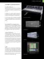
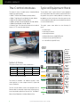
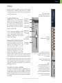
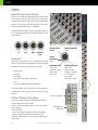
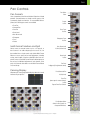
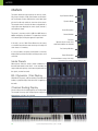
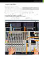
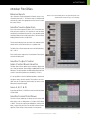
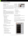
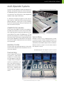
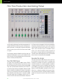
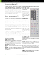
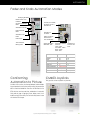
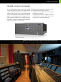
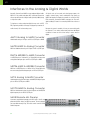
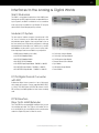
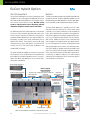
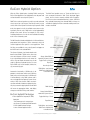
System 5 Digital Audio Mixing System - InDepth
1
EUPHONIX - SYSTEM 5 INDEPTH
Table of Contents
System 5............................................................................................................................ 4
System 5 Key Features..................................................................................................... 4
Innovative Solutions......................................................................................................... 4
System Components........................................................................................................ 5
The Control Modules........................................................................................................ 6
Typical Equipment Rack.................................................................................................. 6
System 5 Control Surface - 6 Module Frame................................................................ 7
Channels........................................................................................................................... 8
Strips................................................................................................................................... 9
Inputs............................................................................................................................... 11
Channel Process Order................................................................................................. 12
EQ & Filters...................................................................................................................... 12
Dynamics........................................................................................................................ 13
Bus Routing and Aux Sends........................................................................................... 14
Pan Controls................................................................................................................... 15
Meters . ........................................................................................................................... 16
Master Facilities.............................................................................................................. 17
Multi-Operator Systems................................................................................................. 23
Film Post-Production Monitoring Panel ....................................................................... 24
System 5 Multi-Operator Configuration ...................................................................... 25
SnapShot Recall™.......................................................................................................... 26
Total Automation™ ....................................................................................................... 26
Fader and Knob Automation Modes.......................................................................... 27
Conforming ................................................................................................................... 27
CM403 Joysticks............................................................................................................. 27
Patching - PatchNet...................................................................................................... 28
File Management........................................................................................................... 29
DF66 DSP SuperCore with MADI I/O & Router............................................................ 30
SC263 Studio Computer................................................................................................ 31
Interfaces to the Analog & Digital Worlds................................................................... 32
EuCon Hybrid Option..................................................................................................... 34
Digital Factory, Normandy, France............................................................................. 36
System 5 InDepth
Version 12a
All system specifications are subject to change without notice
euphonix.com
Copyright © 2009 Euphonix Inc. All rights reserved. MC Pro, System 5, System 5-MC, S-5, PatchNet, eMix, EuCon, StudioHub, GainBall, SnapShot, SnapShot
Recall are trademarks of Euphonix Inc. Other products mentioned are the trademarks of their respective manufacturers.
Specifications are subject to change without notice.
Euphonix Inc., 1330 West Middlefield Road, Mountain View, CA 94043, USA. ph: (650) 855 0400 fax: (650) 969 3510
2
System 5 Digital Audio Mixing System - InDepth
EUPHONIX - SYSTEM 5 INDEPTH
System 5 Two-Operator Console
Shepperton Studios, U.K.
System 5 Digital Audio Mixing System - InDepth
3
INTRODUCTION
System 5
System 5 is a high performance digital audio mixing system
specifically designed for audio post-production and music applications. System 5 has been re-engineered to add a host of
new features ..
• New Control Surface
- New touch-sensitive LED color-coded knobs
- New higher-resolution TFT screens
- Faster processors and more memory
- Improved fader resolution around 0dB
• New EuCon Hybrid Option
- Control multiple DAWs from the System 5 Surface
- Save Layouts of DSP and DAW tracks together
System 5 Key Features
• Easy to use and learn—intuitive interface
• New software features
- Aux to faders
- Scene automation
- Dual zone Spill area
- Buses can be controlled from Strips
- Bus processing
• New DSP SuperCore & Studio Computer
- Faster and more powerful
- More channels & buses
- Supports bus processors
- Fewer rack components
- Up to 1,536x1,536 router (24x24 MADI)
• New modular converters including SDI support
Innovative Solutions
• Modular surface and I/O design
Layouts
• Constant visual feedback for the operator
Place sources anywhere on the surface and save the positions
as Layouts for fast access to tracks you need the most.
• Highest sound quality
• Star format Ethernet module interconnection resulting in
more secure operation and no communication bottleneck
• Mixer Channel & Bus Size:
- modular up to 300 channels
- each channel has 4 band EQ, dynamics and two filters
- up to 48 mix buses, 48 group buses, 24 aux sends, 72
Multi-Format Masters
Control a surround sound source on one fader.
Spill
Spill brings all the elements of Multi-Format Master to the surface for individual adjustment.
external inputs
• High-resolution LED meters next to each fader
• 240 SnapShot Recalls of all console settings
• 48 Layouts for different surface configurations
• PatchNet - digital router/patchbay
• Surround panning and monitoring as standard
• Spill function for easy access to multi-format sources
With Spill the 5.1 (or any other format)
Multi-Format Master is ‘spilled’ out to
its six discrete elements for individual
control
• 8 Knobs & 100mm touch sensitive moving fader per strip
• TFT high-resolution displays at the top of each channel
for metering (up to 5.1), EQ, dynamics & pan graphs and
routing
• Dynamic automation of most parameters to timecode
• Conform to picture
• Comprehensive machine control facilities integrating with
Soundmaster, Colin Broad, Tamura and JSK
• Up to 3-operator configuration
4
EuCon Hybrid Option
The new EuCon Hybrid option lets System 5 control multiple
DAWs simultaneously bringing DAW tracks onto the console
surface for mixing. No other control system or console
comes close to the power and total integration of
Euphonix control surfaces with EuCon.
System 5 Digital Audio Mixing System - InDepth
SYSTEM COMPONENTS
System Components
Control Surface
Much like any audio console the System 5’s surface includes
channel strips and a center section for master facilities. The
surface is modular, making it easy to add extra channel strips
at any time.
Connections to the rack are Cat 5 Ethernet so placement is not
restricted by complex cabling. No audio flows through the control surface as the audio electronics are housed remotely.
The console surface controls the Euphonix DSP SuperCore
and, with the EuCon Hybrid Option, can control DAW tracks
on multiple external DAWs via the EuCon control protocol over
Ethernet .
System 5 Control Surface
New Digital Processing Core
Audio signals are processed in the new modular DSP SuperCore
which includes DSP for channels, MADI I/O and a router
(patchbay). The DSP SuperCore easily handles 24-bit 48kHz or
96kHz audio up to 40-bit floating point processing and is hardware capable of even higher sample rates up to 384kHz.
DSP SuperCore
Audio Interfaces
Audio Interconnections use AES10 MADI (up to 64 channels
of 24-bit digital audio data carried on a single 75ohm coax
cable or fiber). To interface the console to the outside world,
multi-channel digital and analog converters, digital format
converters with sample rate conversion, as well as remote
mic/line input amps, are available. Cabling is simplified because converters can be placed next to the equipment they
interface to. The modularity means that the balance between
analog and digital I/O can be tailored to the specific needs
of the facility.
Converters
eMix
Operations such as system setup, file management, patching, and diagnostics are managed by a program called eMix
which runs with a screen and keyboard, usually situated next
to the console. PatchNet, a powerful digital patching system
that handles patching for all the console’s inputs and outputs,
replaces a traditional patchbay with a system that can store
and recall every single patch that is made.
eMix Software
System 5 Digital Audio Mixing System - InDepth
5
CONTROL SURFACE
The Control Modules
Typical Equipment Rack
The System 5 surface is modular and can include 6 different
modules (see opposite page) :
• CM401-T Master Control Module (1ft wide, 305mm)
• CM402-T Sub-Master Control Module (1ft wide, 305mm)
• CM403-F/J Film Module (1ft wide, 305mm)
• CM408-T 8-Fader Channel Strip Module (1ft wide, 305mm)
• CM409-F Blank Module (1ft wide, 305mm)
• Producer’s Desk - Flat worksurface with provision for built-in
high-res 23” TFT screen (2ft wide, 610mm)
The rack below shows a typical System 5 system equipment
rack. Further details about the converters may be found later in
the guide. As the system is modular, additional converters may
be added at any time in the future to allow the system to grow
to match production needs and to match the digital/analog ratio
of sources and destinations.
Producer’s Desk
The typical system shown below has the following I/O
totals:
• 24 Mic Sources
• 26 Analog Line Sources
• 26 Analog Destinations
• 56 Digital Destinations (28 AES/EBU pairs)
• 56 Digital Sources (28 AES/EBU Pairs)
• 4 to 24 MADI I/O (4 per DSP Card)
Ethernet
EuCon to
Surface
Ethernet
Switch
SC263
Studio
Computer
System 5 Frame
DF66 DSP
SuperCore
Up to 6
SP662 DSP
Cards
MADI
The System 5 Frame comes in three standard sizes.*
Trim
Frame
Height
Width
Depth
6 modules
39.5” (1 m)
6’10” (2.08m)
41” (1.04m)
9 modules
39.5” (1 m)
9’10” (3m)
41” (1.04m)
12 modules
39.5” (1 m)
12’10” (3.9m)
41” (1.04m)
1-8
1
2
3
4
5
6
7
8
9-16
9
10
11
12
13
14
15
16
17-24
17
18
19
20
21
22
23
24
96
48
44.1
CUSTOM
A1
TRIM
A2
SR
CONV
D1
AES
WORD
INTERNAL
AUTO
D2
MONITOR-COMMS INTERFACE
MC
524
Monitors
FORMAT A
CH 1-8
SRC ENABLE
ON (STD)
* Custom Frame sizes are available.
OFF
Two frames are available - the traditional System 5 frame
shown opposite, or a more compact frame this is lighter and
more cost effective.
24 Mics
MADI
SDIF-2
PRODIGI
TDIF
ADAT
PROTOOLS
AES
SRC
MADI
SDIF-2
PRODIGI
TDIF
ADAT
PROTOOLS
AES
SRC
16
20
16
20
16
20
24
24
OUTPUT BIT
DEPTH
OUTPUT BIT
DEPTH
3
4
5
6
7
8
11
12
13
14
15
16
21
22
23
24
24
OUTPUT BIT
DEPTH
2
20
CH 49-56
MADI
SDIF-2
PRODIGI
TDIF
ADAT
PROTOOLS
AES
SRC
10
19
CH 41-48
MADI
SDIF-2
PRODIGI
TDIF
ADAT
PROTOOLS
AES
SRC
16
20
9
18
CH 33-40
MADI
SDIF-2
PRODIGI
TDIF
ADAT
PROTOOLS
AES
SRC
16
20
1
17
FORMAT CONVERTER
CH 25-32
TDIF
ADAT
PROTOOLS
AES
SRC
OUTPUT BIT
DEPTH
MADI
CH 17-24
MADI
SDIF-2
PRODIGI
16
20
24
ON-ALT
56 Digital
In and Out
CH 9-16
MADI
SDIF-2
PRODIGI
TDIF
ADAT
PROTOOLS
AES
SRC
16
20
24
OUTPUT BIT
DEPTH
OUTPUT BIT
DEPTH
FORMAT B
96
48
44.1
CUSTOM
AES
WORD
MADI
FORMAT A
AUTO
24
OUTPUT BIT
DEPTH
MIC LINE INTERFACE
24
Trim
1
2
3
4
5
6
7
9-16
9
10
11
12
13
14
15
16
17-24
17
18
19
20
21
22
23
24
1-8
8
96
48
44.1
CUSTOM
A1
TRIM
A2
D1
SR
CONV
D1
SR
CONV
AES
WORD
INTERNAL
AUTO
D2
Trim
The main console modules connect to the equipment rack via
Ethernet cables for extremely simple hookup, allowing the surface to be placed long distances from the rack. The CM401-T
Master Control Module also includes talkback wiring.
6
1-8
1
2
3
4
5
6
7
8
9-16
9
10
11
12
13
14
15
16
96
48
44.1
CUSTOM
26 Analog
In
17-24
17
18
19
20
21
22
23
24
A1
TRIM
A2
AES
WORD
INTERNAL
AUTO
D2
Trim
1-8
1
2
3
4
5
6
7
8
9-16
9
10
11
12
13
14
15
16
17-24
17
18
19
20
21
22
23
24
96
48
44.1
CUSTOM
26 Analog
Out
System 5 Digital Audio Mixing System - InDepth
A1
TRIM
A2
D1
SR
CONV
D2
AES
WORD
INTERNAL
AUTO
FC
726
MA703
DAC
Monitors
MC524
Monitor
Controller
FC726
Digital I/O
1-56
ML530
Mic Pre
1-24
AM713
ADC
Mic Pre
AM713
ADC
1-26
MA703
DAC
1-26
Color TFT Display
in each module
CM408-T
8 Fader Channel Strip Module
Optional CM402-T
Sub-Master Control Module
CM401-T
Master Control Module
Optional CM403-F/J
Film Module with PEC Direct
Panel and Joysticks
System 5 Control Surface - 6 Module Frame
CONTROL SURFACE
System 5 Digital Audio Mixing System - InDepth
7
CHANNELS
Channels
The number of cards in the DSP SuperCore determine the number of channels and buses that are available in each System
5. For a given number of cards in the DSP SuperCore, different
combinations of channels and buses may be quickly configured
using the eMix Mixer Model software. Usually a Mixer Model
is chosen during installation and is used throughout the life of
the system as it will best match the application requirements
of the studio.
Each System 5 channel has:
A
B
Channel Inputs
Trim & Phase
• 2 inputs, that may be fed from analog or digital sources
(using appropriate converters), labelled A & B. Either A, B
Input Select
or A & B may be selected to feed the channel.
• phase reverse
• gain trim
• delay up to 2 secs
• insert send & return
• 4 band fully parametric EQ
• 2 filters
• dynamics including compress/expand-gate with hysteresis, key input and side chain filter
• touch sensitive moving fader
• multi-format panning to mix-minus/group and mix buses
• up to 48 group buses
Function
2
1 of 8
7
Delay
Function
2 of 7
Meter
Function
3 of 7
Insert
Function
4 of 7
EQ
Function
5 of 7
Filters
Function
6 of 7
DYN
Any Order
switchable in
pairs of channels
Key
Link
Function
7 of 7
• up to 24 aux send buses
Fader
& Mute
• solo (APL, PFL, SIP)
• 2 direct outputs - pre-fader & post-fader
Post-Fader
Direct Output
• input impedance - hi/lo
• phantom power
• hi pass filter
• analog input gain
8
Solo
PFL/AFL
Aux
Sends
Grp
Pan/Route
Mix
Pan/Route
System 5 Digital Audio Mixing System - InDepth
System Buses
If mic preamps are connected to the channel these additional
controls are available which relate to the ML 530 remote mic/
line interface unit :
Pre-Fader
Output
STRIPS
Strips
System 5 is built up of modules of 8 strips. Controls closely
resemble those of a traditional analog surface. In its simplest
form a single strip controls a single source so a 48 strip surface
could control 48 channels.
Swap (Replace)
TFT Graphic Display:
meters, designation, pan, EQ,
dyn graphs, routing indication
Swap Button
However there is a very useful function
Designations:
called “Swap” which allows single strips,
Swap Source
or every strip, to switch between two chanMain Source
nels. So 96 channels (sources) could easily
be controlled from 48 strips by Swapping
ON & Fader
between the two layers at the push of a
Select/Punch
button (1-48 and 49-96).
Wave Button
System 5 adds further flexibility by allow(brings source
ing any source to be controlled from any
to center)
strip, it is even possible to have two strips
controlling a single source. This is where
Touch
Layouts come into play.
Sensitive
Moving Fader
Knobset:
8 knobs with 4 character
displays
Layouts & Control Groups
The position of sources on the surface can Dual Hi-Res
be saved and recalled as Layouts. For exLED Meters
ample one Layout could be sources 1-48
and another sources 49-96 for a console
with 96 channels and 48 strips. More importantly the most critical sources can be
placed next to the operator. For example,
dialog to the left and music sources to the
right of the center. Different Layouts can be saved so that the
engineer always has the most important sources within easy
reach. Layouts do not save and recall knob and fader settings,
they simply recall the layout of sources on the control surface.
SnapShots are used to save parameter settings. Control Groups
allow a number of faders to be controlled from a single strip.
Layouts can store/recall the entire desk or only certain strips
defined by the operator.
Central Control of Strips
The Master Control Module includes a complete strip for central control of any source. The optional CM402-T module also
includes additional knobsets that are available for control of EQ,
dynamics, aux sends, filters, input and routing at the same time.
Pressing the Wave key next to a source fader brings that source
to the center.
Knobset Function Select:
selects the 8 knobs to control
Input, Dyn, EQ, Filters, Aux, Pan
or Routing
Swaps the Strip between the
Main and Swap Source
Fader:
twin 4-character designations
(that may be linked to the facility router), solo, channel on,
channel select key for bringing
up the source in the center of
the console, 100mm long-throw
touch-sensitive motorized fader,
twin hi-res LED meters
System 5 Digital Audio Mixing System - InDepth
9
STRIPS
Strips
New Rotary Touch Knobs
System 5 uses unique rotary illuminated touch-sensitive knobs
that instantly reset after a recall. The center of the knob also
includes a switch which can be used for certain knobset select
functions, and to punch in the knob automation, if the touchsensitive knob automation option is switched off.
The displays reflect the type of control, for example a gain control is shown opposite. Below are the different displays for different functions:
Knob with Push
Switch
Q
Pan
Gain
Frequency
&Q
Knobsets
At the top of each strip are a set of 8 knobs with associated
switches. These knobs can be selected to control the following
parameters using the switches just below the knobs:
• Input Controls
• Dynamics
• EQ & Filters
Switch
Automation
Write
Knob Status LEDs
Touch - Blue
Auto-Glide - Yellow
Read - Green
Write - Red
• Aux Sends - level, pre/post and routing
• Pan
• Routing to Group/Clean Feeds and Mix Buses
The selected button in this photo shows that the knobset is
controlling EQ. To the left of these keys are processor In/Out
switches.
Processor In/Out Keys
Other Channel Functions
Here are just some extra functions available to the engineer:
• Copy and Paste one strip to another
• Use a single strip to select function such as EQ, Dynamics,
Aux for all strips
• Clear all controls
• Lock a strip to prevent changes when the Layout changes
• Select a strip to be controlled from the center section
• Expand a strip so that EQ, Dyn, etc. controls are spread across
several strips
10
Bright Orange LED
Pointer
Knobset Function
Select Keys
System 5 Digital Audio Mixing System - InDepth
Knob Function Color
Input - Red
Expand - Green
Compress - Turquoise
Pan - Dark Blue
Aux - Yellow
EQ & Filters - Violet
INPUTS
Inputs
Each channel has two digital inputs labelled A and B. Controls
for each input include:
• Phase Reverse
• Delay
• Input Select (A, B, or A+B)
Patching Input Sources
(PatchNet)
The PatchNet routing system (see page 28) is used to patch
sources to inputs. Any sources within the system, such as mixminus/group outputs or externals may be sent to these inputs.
External MADI inputs can also be directly patched. For Analog,
AES/EBU and other digital sources the Euphonix converters are
used. See the Converter section for details (page 32) .
Analog Controls - ML 530 Mic/Line Interface
• Gain Trim
Impedance
High Z/Low Z
Phantom
In/Out
High Pass Filter
In/Out
Analog Mic/Line Gain
Mic/Line Preamp
Gain Trim
Phantom
Impedance
Hi-Pass
Analog Gain
Analog to Digital
Converter
Chan A In
Chan B In
(Digital)
(Digital)
This can also act as a direct box,
providing correct impedance
matching with balanced outputs
plus the benefit of gain control.
A Trim
(Digital)
B Trim
(Digital)
A Phase
B Phase
Digital Controls - A Input shown
For variable gain analog mic inputs Euphonix provides the ML
530 with 24 mic/line input preamps and the AM713 analog to
digital converter. If this is connected to the system the controls
for phantom power, input impedance, high pass filter and gain are
available on the channel strip.
Phase
In/Out
Delay (up to 2 secs)
In/Out
A/B Select
A
B
Input Switch: A, B, A&B
Delay
Page to additional controls:
Input A, Input B, Processor In/Out
24 Microphones
ML530 Mic/Line
1
2
3
4
5
6
7
8
9
10
11
12
13
14
15
16
17
18
19
20
21
22
23
24
MIC LINE INTERFACE
ML
530
Input Function Selected
24 Analog Line Level
AM713 Analog to MADI
ANALOG TO MADI
Trim
1-8
1
2
3
4
5
6
7
8
9-16
9
10
11
12
13
14
15
16
17-24
17
18
19
20
21
22
23
24
96
48
44.1
CUSTOM
MADI to
StudioHub Router
A1
TRIM
A2
D1
SR
CONV
AES
WORD
INTERNAL
AUTO
AM
713
D2
TCC Control
System 5 Digital Audio Mixing System - InDepth
11
EQ
Channel Process Order
EQ Select
Clear
High Band
Freq/Q Page
Freq Adj
Peak/Shelf
Each channel has an insert point which can be placed in any of
the seven process positions. The Euphonix converters provide
analog and digital I/O for insertion of any type of device, such
as a delay line, into the signal path.
There are 7 processing sections:
• Delay
• Metering Source
• Insert Point
• EQ
• 2 Filters
• Dynamics
• Fader and Mute
Any Order
switchable in
pairs of channels
Function
2 of 7
8
1
Delay
Function
2 of 7
Meter
Function
3 of 7
Insert
Function
4 of 7
EQ
Function
5 of 7
Filters
Function
6 of 7
DYN
Gain Adj
High Band In/Out
High Mid Band
Freq/Q Page
Freq Adj
Key
Link
Function
7 of 7
Fader
& Mute
These can be arranged in any order using the eMix application,
even when passing audio, but must be re-ordered at least two
adjacent channels at a time. For example, the EQ may be set to
follow dynamics, the insert may be placed after the EQ or dynamics, and metering, can be placed after the fader, on channels 1
and 2, or on channels 1-8.
EQ & Filters
The EQ controls are shown opposite. Euphonix has a wellearned reputation for the highest quality EQ algorithms with
an uncompromised approach to design. System 5’s equalizer
is much more than just a simple EQ. The four bands are each
fully parametric, with additionally switchable peak/shelf selection on two of the bands. Frequencies are not limited to fixed
ranges; each band covers the entire 20Hz - 20kHz spectrum,
with a gain +/- 24dB and local variable Q control. The Page key
at the bottom of the knobs brings up the Filters. There are two
Gain Adj
High Mid Band In/Out
Low Mid Band
Freq/Q Page
Freq Adj
Gain Adj
Low Mid Band In/Out
Low Band
Freq/Q Page
Freq Adj
Peak/Shelf
Gain Adj
Low Band In/Out
Filters that can each be set to: High Pass, Low Pass, Band Pass
or Notch. Each filter has a frequency control. The notch filter
includes Q control and a “boost/listen” function, monitoring the
audio without the filter in the circuit, to help identify any problematic frequency prior to selection. A 50/60 Hz hum, or other
unexpected noise problem can be taken care of without disturbing the program mix or compromising any equalizer settings as
with shared designs.
Page Keys to Filters
EQ Display
Whenever an equalizer is being adjusted a graphical display appears to illustrate what the processor is doing to the audio at
the top of the channel.
12
System 5 Digital Audio Mixing System - InDepth
EQ In/Out
EQ Knobset
Select
DYNAMICS
Dynamics
Dynamics Select
Clear
Compressor
The System 5 has an extremely powerful dynamics section
comprising of a Compressor/Limiter, an Expander/Gate and side
chain key input with filter. System 5 allows both Compress and
Expand sections to be used together. The knobset shown opposite is the simple Compress/Expand knobset with the main
controls for both sections available. The page keys at the bottom allow the knobset to be switched to a further 3 sets of
knobs that give more advanced control. Here are the full set of
parameters that can be adjusted:
Release
Attack
Compressor
Threshold
Release
Attack
Threshold
Ratio
Ratio
Compressor In/Out
Expander
Depth
Knee
Gain Make Up
Release
Compressor In/Out
Expander/Gate
Release
Attack
Attack
Threshold
Ratio
Threshold
Depth
Knee
Hold
Hysteresis
Ratio
Expander In/Out
Expander/Gate In/Out
Side Chain
Page Keys
Filter Type - Hi Pass, Lo Pass, Band Pass, Notch
Side Chain Listen
Side Chain Source - Channel, Key Input, Link
Detector Type - Peak, Average
Dynamics In/Out
Dynamics Knobset Select
Dynamics Display
Whenever dynamics are being adjusted a graphical display is
shown on the display at the top of the strip to illustrate how the
processor is affecting the audio.
System 5 Digital Audio Mixing System - InDepth
13
BUSES & ROUTING
Bus Routing and Aux Sends
Aux Select
Clear
Number of Buses - Mixer Models
The number of Mix, Group and Aux buses available in a System 5 console is dependent on the number of cards in the DSP
SuperCore and the selected Mixer Model. Additional DSP cards
may be added at any time to increase the number of channels.
(Aux 1 & 2 are setup as stereo)
Aux 1 & 2 Pan
Pan In/Out
Bus Processing
Pre/Post
Aux 1 & 2 Level
Aux 1 & 2 On/Off
The new DSP SuperCore supports dedicated bus processing
comprising filters and dynamics that can be attached to any mix,
group or aux bus and controlled from a Strip.
Pre/Post
Aux 3 Gain
Aux 3 On/Off
Mix Buses
The mix buses are grouped in Sections (Stems) to allow mixing
to different formats. For example, a stereo mix section has two
individual buses and a 5.1 mix section has six. Up to 16 mix sections may be simply configured from the eMix setup software and
each may be given a name. System 5 supports up to 48 individual
mix buses. Formats are Mono, Stereo, LCRS, 5.1, 6.1 and 7.1 plus
custom formats. Routing a source to a Mix Section is done from
the switches on the Knobset after first pressing the Route - Mix
key. Just as with the Aux sends, as shown right, each On/Off key
switches the signal to that bus section. The channel signal may be
routed to all buses in that section with or without the pan inserted.
It is also possible to route to individual buses (direct assign) in each
section, for example, just the center bus of a 5.1 mix section.
Pre/Post
Aux 3 Gain
Aux 3 On/Off
Pre/Post
Aux 3 Gain
Aux 3 On/Off
Pre/Post
Aux 3 Gain
Aux 3 On/Off
Group Buses
Pre/Post
Aux 3 Gain
Aux 3 On/Off
Up to 48 audio group/DAW send buses are available. They can
be set to any format from mono thru 7.1. Routing is similar to Mix
buses by pressing the Route - Group key then using the knobset On/
Off switches. For traditional sub-group control these buses may be
brought back into channels that can act as audio sub-group masters
- note that dedicated bus processing is also available. The Group
knobsets also include an overall group send level control.
Pre/Post
Aux 3 Gain
Aux 3 On/Off
Aux Page To Additional Sends
Aux Send
Up to 24 Aux sends are available and can be configured in mono
or stereo pairs. Press the Aux function key to bring up the Aux
sends on the knobset. The example on the right shows typical
Aux sends with 1 & 2 working as a stereo send with pan. Sends
can be individually set to feed pre or post-fader and can be used
as effects sends or foldback sends. Aux masters are controlled
from the center section and include individual talkback and tone
insert provisions. Each send may be named to reflect its destination. Aux sends can be flipped to be controlled from the faders
- very useful for setting complex monitor mixes and sends.
14
Aux Knobset Select
Group and Mix Routing
Knobset Select
System 5 Digital Audio Mixing System - InDepth
PAN
Pan Controls
Pan Select
Clear
Pan Formats
Years of experience in the film world allows Euphonix to include
powerful surround features not found on other systems, with
an extremely simple user interface. For surround Mix Sections
(Stems) the following pan controls are available:
Rotate
In/Out
• Front Pan
• Surround Pan
Focus Front
On/Cut
• Rear Pan
• Boom Level
• Non-Boom Level
• Divergence
Divergence Front
On/Cut
• Focus
• Rotate
Multi-Format Masters and Spill
Stereo sources or surround sources such as a 5.1 pre-mix, or
the 6 sources in an audio sub-group (in the case of 5.1) can
be controlled from a single control strip called a Multi-Format
Master to save on space and to make adjustments, including
routing, much simpler. A function called Spill allows the component sources of the Multi-Format Master to be brought up on
the surface, for individual adjustment of each element, at the
push of the channel select button on the Multi-Format Master
or Control Group.
Panning Display
Whenever pan is being adjusted the display above the channel
indicates the pan position.
Non-Boom Level
In/Out (follow front)
Boom Level
In/Out
Pan Rear
In (bypass)/Out (phantom center)
Front/Surround Pan
In/Out (front)
Front Pan
(stereo pan for stereo formats)
In/Out
Page to Extra Pan Controls
Pan Knobset Select
Switch In Pan Controls to
Group and Mix Buses
System 5 Digital Audio Mixing System - InDepth
15
METERS
Meters
The meters above each strip may be set to show any source,
Mix, Group or Aux bus. Single or dual meters can be selected. For example, all strips could have the source fader signal
plus the first 48 strips could also show the mix bus levels.
The example shown to the right has been configured with a
single input meter displaying the source signal (channel 1)
and a dynamics meter.
The meter is accurate to within 1/4dB from 0dBfs down to
48dBfs and displays clip indication. The green bar to the left
of the meter lights showing the approach to peak level.
If the strip is set to a Multi-Format Master that has stereo
or surround format then the meter at the top of the strip will
show stereo or 5.1 metering.
It is also possible to set up the channel meters so that they
display metering for both the Main and Swap sources at the
same time.
Meter Presets
High Resolution Meter
Dynamics Meter
Source Designation
Channel Number
EQ Curve
(dynamics & pan curves show
when their knobsets are selected)
Bus Routing Indication
Button Designation
(for the two buttons at top of the strip)
Screen at the top of 8 strips showing 8 channel meters
Meter presets allow the setup of meter combinations to
be stored and named for later recall - 24 are available. One
setup could contain primary source meters together with mix
bus signals, another Aux sends.
EQ / Dynamics / Pan Display
Whenever EQ, Dynamics, and Pan are being controlled on the
knobset, a graphical display illustrates what is happening to
the audio.
Channel Routing Display
Source routing to the mix and group buses are also displayed.
The example shown top right is displaying the routing to the
48 group buses, with bus 1 & 2 selected.
16
System 5 Digital Audio Mixing System - InDepth
MASTER FACILITIES
Master Facilities
Central Assignable Controls
A source can be brought to the center section strip in the CM401T Master Module either from one of the strips, by pressing the
Wave key, or by selecting a channel from the 32 keys on the
optional CM402-T Sub-Master module. These 32 keys, together
with source names and ON keys, are located just above the 8
assignable faders and can scroll through all the channels and
control groups on the console. Once a strip has been brought to
the center, control is exactly the same as on a strip elsewhere
on the console. The CM402-T module, as shown below, has 40
Optional CM402-T
Sub-Master Module
Central Input, EQ,
Filters, Dynamics,
Aux, Pan, Channel
Controls
32 Channel
Select Keys
with Name
Displays
Group & Mix Route Buttons
extra knobs together with more displays and switches that are
available for expanded EQ, Dynamics, Aux, Input, Group and
Mix bus controls. The screen at the top shows extra metering
and larger graphs for EQ and Dynamics.
8 Assignable Strip Faders
At the bottom of the optional CM402-T are 8 faders. These can
be assigned to control any channel, control group or multi-format master.
CM401-T
Master Module
Aux / Group / Mix Bus Masters
Central Channel Assign Area
4 x SLS/Cue Controls
Main Panel
Solo/AFL/PFL
Main Monitor
Control & Display
Sub Panel
Central Assign Strip
Master Fader
8 Assignable Faders
Quick Access Panel
System 5 Digital Audio Mixing System - InDepth
Transport & Locate
Automation Controls
17
SUB-MASTER MODULE
Master Facilities
CM402-T 32 Source Select Keys
These 32 buttons in the optional CM402-T module make it very
easy to move around the console from the sweet spot. The
display shows the channel name, and the right button beneath
each display selects this channel to the center strip. The left
button can act as an On/Off or a Solo button. The Page keys
at the bottom allow the 32 buttons to page to more channels.
These controls may also be switched to select control groups.
CM402-T Central Knobsets
Aux
Dynamics
18
Filters
EQ
System 5 Digital Audio Mixing System - InDepth
SUB-MASTER MODULE & BUS MASTERS
Master Facilities
Dynamics & EQ
Once a source has been brought to the center, the two sets
of knobs at the bottom of the CM402-T Knobset Panel allow
dedicated control of dynamics (12 left knobs) and EQ (12 right
knobs). Functions are exactly the same as those found in the
strip controls. The CM402-T display includes simultaneous dynamics, EQ and filter graphics to show the processor settings.
Upper Knobsets - Aux, Filters & Inputs
At the top of the CM402-T panel are two sets of 8 knobs that can
be switched to control Aux Sends, Filters, and Inputs. The functions available are exactly the same as those found in the strips.
CM402-T 48 Routing Keys
These 48 keys allow group and mix section routing on dedicated
keys.
Bus Masters
Bus Masters are controlled from the 8 knobs and function select switches in the middle of the console. The knobset can be
switched between Group, Mix and Aux Bus Masters using the
function select keys at the bottom of the knobset. The page key
allows the 8 knobs to switch between sets of 8 controls (1-8,
9-16 etc.)
Each master has a gain trim and On/Off switch plus an insert.
For a Mix Section this will control the gain of all the buses within the section. For the Mix Masters the upper switch next to
each knob switches the knobs to allow On/Off and gain trim for
individual buses within each Section. The user can lock the bus
masters so the point of reference is always the same.
Bus Masters
Bus Designation
Mix Section Expand
Bus Level
On/Off
Page Keys
Bus Master
Knobset
Function Select
Master Fader
The Master Fader in the middle of the center section controls all
Mix Section output levels. It can also be locked out.
System 5 Digital Audio Mixing System - InDepth
19
MASTER METERS & MONITORING
Master Facilities
Main Panel
Master Meters
The flat screen display above the center section includes metering for main monitor outputs. The number of meters will match
the monitor’s format (5.1 is shown in the example below).
The 8 meters at the bottom of the screen are for Aux, Group,
Mix outputs or the SLS/Cue monitors, depending on the bus
master knobset selection.
The main panel in the center section is used for making monitor
selections as well as for many other functions including saving
and loading Layouts, Meter Presets and SnapShots. It is very
simple to operate with a straightforward menu structure and
designations which describe functions next to the actual keys.
The External Monitor Selection is shown opposite for selecting
external sources to the Control Room Monitors.
Main Panel
(Currently switched to Solo Options)
4 SLS/Cue
Mon Outs
Solo, AFL, PFL
System 5 includes:
• Solo-In-Place (SIP)
• After Pan Listen (APL)
• Pre Fader Listen (PFL)
• Fader Backstop PFL
• Solo Safe - for isolating effects returns
from Solo-In-Place
The solo control knob in the center section allows the level of
APL and PFL to be set and pressing the top of the knob will clear
any solos. There is also a solo active LED.
Solo Options:
• Inter-cancelling, Momentary or Latching Solo switches
• Solo (AFL, PFL) can be sent to either of the two alternate
speaker outputs or can be sent to whichever is the currently selected speaker
• Solo can dim the monitors
Monitoring
System 5 has five monitor outputs; Control Room (main and two
alternates), and the SLS/Cue outputs Mon A, B, C and D. Each
of the 5 monitor feeds can select from external inputs configured as External Devices, the Mix Sections (Stems) both bus
and playback return, and the aux sends.
CR Monitor
Solo
Externals
Mix Stems
Stem
Alt 1
6 Out (max 5.1)
CR
Monitors
8 Out (max 7.1)
The format of the main control room monitors, and Mon A can
handle up to an 8 output surround format. Even the Alt 1 outputs
can handle 6 speakers which is very useful for a second set of
control room speakers when mixing in surround. Group outputs
are usually monitored on the strips but can also be picked up by
the External inputs using PatchNet.
Alt 2
Stereo
Mon A
8 Out (max 7.1)
Mon B
Stereo
Mon C
Stereo
Mon D
Stereo
Monitor Selector
20
Main
8 Out (max 7.1)
Aux Sends
Stem
Rtn
System 5 Digital Audio Mixing System - InDepth
MONITORING
Master Facilities
External Inputs
Up to 32 devices may be configured for External sources in any
surround format up to 7.1. The monitor matrix is intelligent and
automatically selects the appropriate monitor format to match
the source’s format.
Monitor Section and the Main panel to the right. Main panel shows
the Main Menu with all the major section headings
Monitor Source Selection
Each of the monitor outputs (CR, Mon A, B, C, D) have their own
level and source select key. It is important to note that these
are digitally controlled analog controls as they provide a quiet
and highly stable monitor output stage which is essential when
feeding powerful monitors at high levels.
The 8-character display shows the name of the selected source
and the switch on the level knob acts as a speaker mute.
The Main Control Room feed can be sent to the Main Monitors,
Alt 1, or Alt 2.
Each of the 5 monitor outputs has a Source button. Pressing this
activates the Main panel.
Monitor Output Control
Main Control Room Monitor
The Main Control Room speaker section includes a digital readout of level, 8-character source display and dedicated Dim and
Mute keys. The active speakers are indicated just above the level
control to show which speakers are switched on (L C R etc.).
It is also possible to switch off individual speakers, set dim level
and phase reverse the Left speaker. These options are accessible from the CR Output key which brings up menus on the
Main panel (see previous page).
Mon A, B, C & D
By pushing the Mon A, B, C & D level control switch these feeds
can be muted.
Monitor Format Fold Down
The Control Room Output key also brings up main monitor fold
down options such as folding down a 5.1 feed to LCRS, Stereo
or Mono. The way the outputs get folded down, and any level
drops, can be set by the user from the eMix software (shown
opposite). These settings can be stored as 24 user presets.
System 5 Digital Audio Mixing System - InDepth
21
COMMUNICATIONS
Master Facilities
Oscillator
Communications
Facilities
System 5 includes a comprehensive communications system
including talkback, listenback, oscillator and slate. The Comms
Ctrl button, just above the main monitor controls, brings up all
the communications options on the Main panel. The Quick Keys
panel (shown opposite) can also used for fast access to comms
facilities.
Digital oscillator again
accessible from the
Comms Control key and
keys on the Main panel.
Features:
• Dedicated 100Hz, 440Hz, 1kHz, 10kHz and user settable
key
• Sine or Pink Noise
Talkback
• Oscillator level control
Two talkback mic inputs are available with phantom power. One
talkback mic is provided and is normally situated in the engineers position, a second can be added for the producer and located elsewhere in the control room. A remote talkback enable
switch input is provided. Mon A, B, C and D are usually used for
SLS or Cue feeds.
• Osc to Mix Sections
• Osc to Mix Minus/Group Buses
• Osc to Aux Sends
• Osc to All above
Quick Access Panel
This panel has 4 sets of 5 keys, factory set for quick access to
commonly used comms features.
Talkback features:
• Talkback to Mon A
• Talkback to Mon B
The four buttons at the top bring up four sets of 5 keys, the one
shown right is the set of talkback keys.
• Talkback to Mon C
• Talkback to Mon D
• Talkback to all 4 Monitors
• Individual level control of each talkback mic
• Talkback keys can latch or be momentary
• Talkback to Aux sends
All these functions can also be found in the main Communication section of the Main Panel as explained opposite. The Quick
Access Panel simply bring the most frequently used keys closer
to the engineer.
• Main CR monitor dims during talkback
• Mon A, B, C or D dims during talkback
Listenback
Four Listenback mic inputs are available. These include phantom power and individual level controls.
Listenback features:
• Listenback to Main Control Room Monitor
• Listenback to Alt 1 Monitor
• Listenback to Alt 2 Monitor
• Listenback can follow CR Speakers
• Listenback to Mon A, B, C, D
• 4 Listenback On/Off Switches
• Listenback can be latching or momentary
• Listenback can be set to dim CR speakers
22
System 5 Digital Audio Mixing System - InDepth
MULTI-OPERATOR SYSTEMS
Multi-Operator Systems
The System 5 can be supplied from single to three-operator configurations, each operator having access to film monitoring panels, dedicated automation, joystick panning and multi-operator
solo functionality. These large systems can be configured with
hundreds of inputs and up to 48 mix buses.
CM403-F/J with Film monitor panel and Joysticks
It is becoming increasingly more popular to install single operator systems for smaller film facilities and long format postproduction applications. These System 5 consoles still benefit
from the film monitoring panels and joystick panning but only
have one automation file system.
CM403-F/J Film Module
The form factor of the CM403 is the same as the standard control module. The architecture is also the same as other modules
with a single Ethernet port connecting the module to the system
via the 100-BaseT Eucon switch. The CM403 houses a TFT and
fits three same-size panels (i.e., the Film Post Panel and/or the
Dual-Joystick Panel). The film panel can be placed above or below the joysticks depending on the preference of the operator.
The user has the option of placing their own motion controller
into the spare panel.
Machine Control
Film environments often require both operators to share control
over the machines. Machine control commands from two consoles can be combined.
Solo-In-Place
Whenever a channel is in solo, on either the primary or secondary surface, any sources currently assigned to the monitors are
temporarily removed (i.e., externals and returns). The monitors
automatically source the direct outputs from the console buses.
When the channel is no longer in solo, the monitors revert to
their setup prior to the solo.
Twin CM403 Film panels in the Shepperton System 5 console with
Colin Broad’s machine control panel top right.
Track Arming
System 5 supports track arming up
to 48 tracks of a single machine
via MMC or P2. The 48 mix buses
are hard-mapped to the 48 tracks.
To support arming over multiple P2
machines (i.e., eight 6-track, six 8track, or two 24-track machines), a
third-party device that distributes
48 tracks from one P2 port to multiple P2 ports is required (contact
customer support for more information).
System 5 Digital Audio Mixing System - InDepth
23
FILM PANEL
Film Post-Production Monitoring Panel
The Film and Post Monitoring Panel fulfills the requirements for
a traditional PEC/Direct monitoring system for the film post-production environment. It can be used in single and multi-operator
System 5 consoles. Up to four Film Post Panels can be installed
in a system.
The Film Monitor module is divided into two distinct parts: the
traditional PEC/DIR panel on the left, and an additional utility
panel to the right. The right panel duplicates most of the master
section’s monitoring and setup functions.
The PEC/DIR Panel
This panel houses the traditional paddles used for PEC/DIR,
Bus/Playback, or Bus/Tape switching. The second sets of paddles are used to put track(s) into record. There are eight paddle
strips, with associated switches above them, and a master control strip. Bus/Tape switching on the paddles is between the Mix
Sections and their associated returns. However, it is possible to
switch not only the whole bus section but the individual buses
(legs). By default, each mix bus section is assigned to a paddle.
The master simply controls all linked bus sections at once, (i.e.,
hit the On switch on the master and all linked On switches turn
24
On). The bus section name appears in the four-character display.
All operations take place within the console’s existing monitor
matrix and affect only the main (CR) monitors. Turn a section On
and it is sent to the monitors (same as the CM401-T monitor
section), solo a section and anything currently assigned to the
main monitors is removed, leaving only the required section.
The Ready switch enables dropping the tracks associated with
the bus-section into record using the record paddle.
Speaker Re-Assign
The system automatically sends mix buses to the correct monitor bus based on the bus section format. For example, when
monitoring FX, the left bus of the section is automatically sent
to the left monitor bus. It is sometimes required to override this
assignment and send a mix bus to a different monitor bus than
was intended. It is possible to use the Exp/Sel keys above the
displays on the PEC/DIR paddle to select buses within a section.
When a bus is selected, the Speaker Re-Assign panel illuminates the current monitor bus assignment. Selecting a different
speaker from the panel re-assigns the bus within the monitor
matrix.
System 5 Digital Audio Mixing System - InDepth
MULTI-OPERATOR CONFIGURATION
CM403 TFT Display
The TFT screen displays meters and an overview of the monitor
bus assignments. The top half of the screen displays metering.
The lower half of the screen displays 48 mix buses across the
top, the first eight bus sections down the side, and the eight
speaker (main monitor bus) outputs.
Metering display showing all Stems
System 5 Multi-Operator Configuration
In a multi-operator film post environment, the user experiences
a single, large console that allows multiple operators. In reality, each section is a unique System 5 console, which allows a
maximum number of channels per operator. The Mix and Solo
buses are normally linked across the consoles. Often the Aux
and Group buses are not linked but local to each operator. In a
two-operator system, one console usually handles the FX and
the other Music and Dialog. Only one console, designated the
Master, uses its monitor matrix. Each operator has a Film Post
Panel located in their section. Although positioned near a particular operator’s surface, each panel is connected to the Master console network allowing access to the monitor matrix.
Metering display showing an expanded Stem
Bus/Track and Monitor Assignments display
MADI
Machine Control
Network
Third-Party Machine
Control/Syncronizer
(Soundmaster, JSK)
Audio Sources
and Recorders
TT002
Converters
DSP SuperCore
Bus Cascade
Converters
DSP SuperCore
Converter
Monitor Controller
Main
Monitors
Film
Panel
Slave Console
Film
Panel
Master Console
Film
Panel
System 5 Digital Audio Mixing System - InDepth
25
SNAPSHOT RECALL & TOTAL AUTOMATION
SnapShot Recall™
A SnapShot stores console settings for recall at a later date.
System 5 supports 240 SnapShots per Title. The operator can
choose which parameters to include in a SnapShot. For example, a SnapShot may include every setting on all channels, a
single channel, or just the EQ or pan settings on a single channel. SnapShots can be named and can also be modified. When
a Title is stored the state of the console is stored in that Title so
when it loads it brings back all console settings.
Automation Performance Control
Several modes are available to modify the main
automation status:
Total Automation™
Preview - When activated
the engineer can preset a
value prior to punching an
object into write. Useful
for writing an abrupt jump
in level.
As System 5 is a fully digital console, it has been designed with
Total Automation in mind. Almost all parameters on the console
may be dynamically automated to timecode including faders,
EQ, pans, Aux sends, dynamics, processor in/out and fader On/
Off.
Suspend Preview - Allows the engineer to quickly switch between the new
value and the underlying
automated value.
The faders are motorized and touch-sensitive, as are the knobs,
which (with their unique illuminated displays) show automation
moves as they playback, with dedicated LEDs showing automation status. Each switch that can be automated has its own
automation punch key.
Capture - Stores in memory the values of objects
which are writing. Punch
Capture allows all these
objects to be punched back
into record at the stored
values.
Join - Stores in memory
which objects were writing when the transport
was stopped (i.e. objects
that were not punched out
manually). The join key allows all these objects to be punched
back into record.
In the center of the console are a set of dedicated automation keys. These are used to select objects for inclusion into
the automation and for selecting the object status. Automation
may be written in small sections, which is more normal for post
work, or can be written as continuous moves throughout the
length of the Title.
Automation Status
Isolate - Object behaves manually.
Read - Object plays back automated move. When playing back
an automated move in READ the engineer can manually override the control or fader by simply touching and moving the control - nothing is written but the manual moves will be heard.
Write Absolute - moves are recorded.
Write Trim - trim moves can be written on top of an existing
move.
Auto Glide - This is a punch out mode for a soft ramped change
between the level at punch out and the underlying level. Glide
time can be user set.
26
Auto Join - Automatically punch all the objects that were
writing when the transport was stopped back into write at the
timecode where the transport was stopped.
Fill - Four keys that allow a level or switch state to be written from the punch out point to the start, or to the end of a
region. Can also write the punch out level or state between two
points.
All Match - Punches out all objects currently writing. Objects
will glide back to previously recorded values.
System 5 Digital Audio Mixing System - InDepth
AUTOMATION
Fader and Knob Automation Modes
Underlying ON Status
Auto Glide
Master / Slave / Link
Indicators
Function (such as EQ,
Dynamics, Pan etc.)
Select/Punch
On Switch read/write
LEDs
Select/Punch for ON
HiF
Fader read/write
LEDs
Select/Punch
for Switch
Select/Punch for
Fader
Fader Touch
Switch (usually an
audio function
such as ON/OFF)
Touch Sensitive
Moving Fader
Switch Automation
Write LED - Red
Conforming
Automation to Picture
Automation LEDs for
the Knob
Touch - Blue
Auto-Glide - Yellow
Read - Green
Write - Red
Select/Punch
switch for the
knob
Automation Mode
Write LED
Read LED
Isolated
Read
Read 'Suspended'
Write Absolute
Write Trim
Writing Automation
In ATO/Glide
In Preview
off
off
off
on
on
medium flash
fast pulse
off
on
fast pulse
off
on
slow pulse
CM403 Joysticks
Twin joysticks can be assigned to any channels.
As video or film sections are inserted, deleted, and moved during post-production, the Conform utility realigns the automation
data to match the edited film. Data from an Edit Decision List
(EDL) with the start time, end time, and duration for each edit,
along with the type of operation (insert, delete, move) is entered into the Conform utility. The Conform utility creates a new
mix with the EDL changes.
System 5 Digital Audio Mixing System - InDepth
27
EMIX-PATCHNET
Patching - PatchNet
System 5 includes a large comprehensive digital patchbay
called PatchNet, operated from the eMix software program
which runs on a monitor next to the console.
Devices
AES/EBU
MADI
Analog
Mic/Line
AES/EBU
MADI
Monitors
Analog
Mic/Line
Audio Interfaces
eMix
MADI
PatchNet is one of the eMix menus. Other menus that are accessible on this computer are the File Directory, Bus Formatting, System Setup, Format Fold Down, External Source Setup
& Conform.
PatchNet
System 5 ’s patching system. PatchNet operates in the same way
as an engineer would make a patch on a traditional patchbay.
First the source is located and selected, then the destination,
and the patch can then be made.
The screen below shows PatchNet in operation. The left hand
side of the screen shows the groups of signals, such as console
A & B inputs, or External Inputs. Once the group of signals is
selected every signal in that group appears on the main part of
screen for patching. Multiple signals can be selected making it
a simple job to patch 48 bus outputs to 48 recorder inputs, for
example.
Patches are saved within Titles. So when the session starts and
the engineer loads the Title, the complete patchbay comes back
exactly as it was left at the end of the last session.
MADI
DSP SuperCore
Control
MADI Router Hub
MADI
PatchNet
MADI
Console I/O
Audio Processing
Control
Default Title
Each studio can set up default PatchNet wiring and naming after installation. This includes naming of all studio patchpoints
such as mic inputs and effects devices. Normalling of standard
connections such as sources to inputs and console outputs to
device inputs can also be setup. These initial settings are similar to the studio wiring, normalling and patchbay labelling in an
analog studio. These default settings are brought into PatchNet
each time a new Title is created. They can be updated at any
time to reflect the addition of new equipment.
Main Category. Click to select other categories of patchpoints
- Console I/O, Device Inputs, Device Outputs or MADI Cabling
Individual Patchpoint list
within a group
e.g. A/B Channel Inputs
Text in a cell indicates
what is patched to that
cell
Sub-Category of patchpoints
e.g. A/B Inputs, Inserts
Patches the selected
patchpoints
Unpatches selected
patchpoints
Tabs page through
patchpoints
Shows all selected
patchpoints as sources
and destinations
Shows log of any failed
patches
Buttons select different eMix screens
28
System 5 Digital Audio Mixing System - InDepth
Unselects all patchpoints
EMIX-FILE MANAGEMENT
File Management
eMix - Directory Screen
eMix
eMix is the management software program for System 5 and
runs on a screen that sits next to the console. The program comprises the following modules:
• Directory
• PatchNet
• System Diagnostics and Mixer Models
• Mix and Group Bus Setup
• Monitor Fold Down Setup
• External Inputs Setup
• Conform (see page 27)
Directory
System 5 has the following file hierarchy: Drives - Projects Titles - Mixes. A project is a folder which contains Titles.
eMix - Main Mix Bus Setup - Creating Mix Sections
A project is like a folder and can be used to house all an operator’s Titles or all Titles in a Show. The Titles are where all the
important data relating to a session is stored.
The directory includes all the features you would expect from a
file management system such as copy, paste, rename, open and
close. The eMix computer includes a large hard disk, recordable
CD-RW drive and floppy drive. The CD-RW can be used to store
and remove Project/Title information. Loading a Title brings back
all the stored information about that title including Last Setup,
Layouts, Meter Presets, SnapShots and, most importantly, the
PatchNet digital patchbay.
PatchNet
eMix - External Inputs Setup
See previous page.
System Mixer Models
eMix allows the combination of channels, buses and externals
to be changed very simply so that the system can be tailored to
each application and installation.
Mix, Group, Fold-Down,
External Setup
Sections of eMix allow the mix and group bus formats, external
formats and monitor fold down to be defined. Up to 48 external
devices are available and can be set to be any format and can also
be named such as 5.1 format DVD player or stereo CD player.
System 5 Digital Audio Mixing System - InDepth
29
DSP SUPERCORE
DF66 DSP SuperCore with MADI I/O & Router
The new lightweight and compact DF66 DSP SuperCore is the
primary signal-processing engine and router for System 5 digital
mixing consoles. It is comprised of a system board and up to six
plug-in SP662 DSP cards. The SuperCore has more than enough
DSP horsepower, system functionality, and reliability to satisfy
today’s demanding music and post applications.
The DSP SuperCore provides:
• DSP Processing - Massive amount of scalable DSP available for fully featured channels and busses with Delay, EQ
& Dynamics processing. Each SP662 card adds 4.8 GFLOPS
of processing power.
• MADI I/O - each SP662 card adds 4 MADI inputs and outputs (256 x 256 paths at 48kHz)
• Router controlled by the console’s PatchNet Software
DF66 DSP SuperCore
SP662 Card
DSP SuperCore Features
The DSP SuperCore is packed with advanced features that stand out from the competition:
• Compact, lightweight, modular and scalable
• Over 300 signal paths per DSP SuperCore at 48kHz
• Independent EQ, filters and dynamics processing per channel
• Up to 2 seconds delay per channel
• Bus processing with dynamics and filters
• 4,096-path FPGA audio router on each SP662 DSP card
• Up to 24x24 MADI I/O (1536x1536 paths @ 48kHz) per DSP SuperCore
• Hardware compatible with 192/384 kHz
• DSPs support 40 bit, 32 bit IEEE floating point and 32 bit fixed point formats
• Hybrid FPGA and DSP technology to accommodate 40 bit floating point (extended precision) operation, for timing precision, and wide feature set
• Parallel signal processing utilizing SIMD (Single Instruction Multiple Data) architecture
• Optional SNMP System Management Controller remotely monitors operating conditions
and notifies the user to take action to avert system failure
• Optional 100% changeover redundancy
30
System 5 Digital Audio Mixing System - InDepth
STUDIO COMPUTER
SC263 Studio Computer
The new SC263 Studio Computer runs the eMix software
which includes the file management system and the PatchNet
software. It includes twin drives set up as a RAID array for redundant storage of all data. There is a separate keyboard and
mouse for this computer and an external screen for showing the
eMix software. Alternatively, instead of an external screen, a
CM411 Video Display Module (similar to a CM409-F blank module but with a TFT display) can be purchased to have the eMix
display integrated into the main console surface.
The SC263 includes an Ethernet port for connection to the System 5 LAN and is fitted with two controller cards:
• TCC Card for controlling ML530 remote mic preamps and
the MC524 monitor controller
• TT002 card for machine control, including a single RS422
port, MMC port, video ref plus 32 GPIO for use with the
console the events system (available Sept 07)
SC263 Studio Computer
System 5 Console at Sydney Opera House Recording Studio
Connected via fiber MADI to Euphonix Consoles in Opera House, Concert Hall & Drama Theater
System 5 Digital Audio Mixing System - InDepth
31
I/O
Interfaces to the Analog & Digital Worlds
Internally, System 5 uses MADI to route and patch digital audio.
MADI is a very stable and robust AES sanctioned format that
allows up to 64 channels of digital audio (at 24-bit, 48kHz) along
a single coax cable.
To interface to analog and other digital formats such as AES/
EBU, Euphonix provides a full range of high quality converters in
multi-channel, 19” rack mounting cases.
All signals such as Aux sends, mix minus/group outputs, mix
outputs, channel inputs, inserts and dynamic key inputs are
MADI and require the Euphonix converters for analog or AES/
EBU connection. Commercial MADI converters are also available including PCI cards for connecting MADI into and out of
PCs.
Because the system is modular, it is easy to start working with
the System 5 in an analog environment and then add digital
converters in future as more of the facility’s sources move to
digital.
AM713 Analog to MADI Converter
26 balanced analog on XLR plus an AES or S/PDIF pair to MADI.
MA703 MADI to Analog Converter
MADI to 26 balanced analog on XLR plus an AES or S/PDIF pair.
DM714 AES/EBU to MADI Converter
13 AES/EBU pairs on 110ohm XLR, or 75ohm BNC, with two extra
analog balanced inputs plus an AES or S/PDIF pair to MADI.
MD704 MADI to AES/EBU Converter
MADI to 13 AES/EBU pairs on 110ohm XLR or 75ohm BNC withtwo extra analog balanced outputs plus an AES or S/PDIF pair.
MI715 Analog to MADI Converter
16 balanced analog line level inputs and 8 AES/EBU digital inputs
plus an AES or S/PDIF pair to MADI.
MO705 MADI to Analog Converter
MADI to 16 balanced analog line level outputs and 8 AES/EBU
digital outputs plus an AES or S/PDIF pair.
ML530 Remote Mic Preamp
24 remote controlled mic preamps with XLR inputs. Usually supplied with AM713 Analog to MADI converter. The mic preamps
are controlled remotely using TCC serial control from the SC263
Studio Computer.
32
System 5 Digital Audio Mixing System - InDepth
I/O
Interfaces to the Analog & Digital Worlds
SH612 StudioHub
The SH612 is a comprehensive professional 12x12 MADI router.
Although the new DSP SuperCore includes complete MADI routing for System 5, the SH612 is available for use as a standalone
router and can be controlled from any Windows PC using the
optional SH612 Route Manager patching software.
Modular I/O System
The new range of modular converters is based around a 3RU
19” chassis conforming to the DIN 41494 specification with
dual redundant power supplies. Cards may be fitted in slots at
the front and the rear for high density configurations. Although
designed primarily for broadcast use, modules such as the SDI
de/embedders may be useful in a post or music facility. 10 different input/output cards are available in any configuration:
• MADI Interface Module (coax or fiber)
• 4 Ch Analog Line Input Module
• 4ch SDI De/Embedder Module
• 4 Ch Analog Line Output Module
• 8ch SDI De/Embedder Module
• 4 Ch Microphone Input Module
• 8ch HD/SD SDI De/Embedder
• Ethernet Remote Control Module
• 4 Ch AES/EBU Input/Output Module - 75Ω BNC or 110Ω XLR
• Sync Module
• 8 Ch AES/EBU Input Module - 75Ω BNC or 110Ω XLR
• 4x Wordclock Output Module
• 8 Ch AES/EBU Output Module - 75Ω BNC or 110Ω XLR
• Power Module
FC726 Digital Format Converter
with SRC
Bi-directional digital format conversion of up to 56 channels
with sample rate conversion. Formats supported; MADI, SPDIF2, ProDigi, TDIF, ADAT Optical, AES/EBU. 56 channels of AES/
EBU are always available regardless of what formats are being
used.
FT730 FiberTran
Fiber Optic MADI Extender
The FT730 FiberTran can extend MADI and Digital Sync for up to
1km over fiber optic cable. The FT730 can also extend TCC control to an ML530 mic pre or the MC524 monitor controller when
used with a Euphonix System 5 or Max Air console.
System 5 Digital Audio Mixing System - InDepth
33
EUCON HYBRID OPTION
EuCon Hybrid Option
Get Connected
EuCon
The new EuCon Hybrid option for System 5 extends the control
capabilities of the console beyond the dedicated DSP Core to
the outside world, bringing DAW tracks from multiple workstations onto the console surface for mixing. No other control
system or console comes close to the power and total
integration of Euphonix control surfaces with EuCon.
The EuCon control protocol makes all this connectivity possible and is
transparent to the user. The EuCon Hybrid Pilot Computer scans the
Ethernet network for available workstations. Any PC or Mac application, not just DAWs, can be controlled from the System 5 surface.
Any DAW running the EuCon Client Application on the network
can have its tracks selected for placement and control on the
System 5 surface. The position of DAW tracks on the surface is
completely flexible. Multiple tracks from separate DAWs may
be placed in any order on the surface simultaneously next to
Euphonix DSP channels. These channel Layouts may be saved,
making them easy to access and organize - one Layout for DSP
channels, one for Pro Tools and one with combinations from
multiple DAWs for example.
This greatly extends the capability of any System 5 console and
allows operators access to DAW tracks that would otherwise
be available only as traditional playback sources. It is now possible to have direct, high-speed access to any of these tracks,
their plug-ins and metering.
The EuCon Client Application is installed on each PC or Mac
workstation for basic connectivity. This allows control surface
commands, such as fader or knob moves, to be translated into
EuCon, HUI or Mackie Control commands for each application.
Native EuCon applications that directly support the EuCon protocol, such as Digital Performer, Nuendo, Logic Pro, Maestro,
MIO Console, SONAR and Pyramix, have an extremely high
level of integration with high-resolution, high-speed connectivity to all of the application’s functions, including multi-channel
metering and EQ/pan curves. Control is fast and highly responsive. EuCon Hybrid also provides extensive high-speed control
of Pro Tools, and Final Cut Pro through a combination of Mackie
HUI or Control Universal protocols and Euphonix-specific protocol extensions. In addition to fader, pan, aux sends, metering
and routing, EuCon Hybrid allows access to the track’s plug-ins
from the 8 knobs on the System 5.
Pro Tools Mac G5
Euphonix DSP SuperCore
EuCon Hybrid
Pilot Computer
System 5 Studio Computer
2 Ethernet Cards
System 5 LAN Bridges the System 5 LAN and
DAW LAN
DAW LAN
Ethernet Switch
Ethernet Router
DVI Switch from
System 5 EuCon
Panel via
USB-GP I/O
Logic Pro Mac G5
Nuendo PC
Pyramix PC
DAD AX24 Converter/Mic Pre
MCs & System 5-MCs
Nuendo
Pyramix
Pro Tools
Pro Tools
Groups
Euphonix DSP Logic Pro
Save and recall different combinations of channels with Layouts
34
System 5 Digital Audio Mixing System - InDepth
Screens DVI
EUCON HYBRID OPTION
EuCon Hybrid Option
With the EuCon Hybrid option installed, DAWs running the
EuCon Client Application are highlighted in the sub-panel and
can be selected for access by the System 5.
DAW Tracks can be assigned to any strip in any order and saved
using Layouts (up to 48 Layouts). Auto-Assign works just the
same as with normal System 5 channel strip assignments. DAW
tracks also appear in the list of available sources when assigning directly from the strip. DAW tracks can be independently
placed on the control surface. For example, Pro Tools track 1
could be placed next to its track 24 which could be followed by
track 14 from a Nuendo system.
The MC Controller includes multiple banks of 24 SmartSwitches,
programmed with keystroke or EuCon commands, which are
saved in Application Sets specific to each application. These
Soft Keys are available for use on the System 5 and appear on
the Main Panel for the selected DAW.
The System 5 includes a jog/shuttle wheel at the
bottom of the CM401-T center section. One of the
most useful features of EuCon control is the ability to assign different functions to this wheel. As
well as Jog and Shuttle the wheel may also be
used for adjusting clip based functions in some
EuCon DAWs such as trim head/tail, fade in/out,
slip, move and clip gain.
Automation functionality of DAW tracks is dependent on the features within each DAW. Any
fader, knob or switch automation for DAW tracks
is written directly to the DAW software and is
not associated with the Euphonix System 5 automation of DSP Core channels. Faders are touchsensitive and knobs include auto-pickup functionality. Any automation playing back from the DAW
will move the appropriate faders, and display
changes on the knob LED rings and switches.
EuCon Hybrid Package
• EuCon Hybrid Pilot Computer (PC 254h)
fitted with:
- Two Ethernet ports for connecting to
the System 5 and external DAW networks
- EuCon Hybrid Software Package
- Latest software Application Sets
The Main Panel provides access to Tracks and Soft Keys for
each connected workstation. With Tracks displayed (upper
photo), the list of tracks currently available from the application in focus on the connected workstation is shown. With Soft
Keys selected (lower photo) the selected DAWs soft keys are
available for sending out EuCon commands and Keystroke commands to the DAW.
Main Panel
DAW Track Select
with Name (1st 8 chars)
Setup - Select DAWs on
network for System 5 access
Toggle Tracks or Soft Keys
Page Tracks
Auto-Assign Tracks
DAW Select - push to bring
DAW Tracks and Soft Keys
to the Main Panel
Sub Panel
DAW Soft Key
Setup - Select DAWs on
network for System 5 access
Toggle Soft Keys or Tracks
Page Soft Keys
DAW Select - push to bring
DAW Tracks and Soft Keys
to the Main Panel
System 5 Digital Audio Mixing System - InDepth
35
System 5 Digital Audio Mixing System - InDepth
Digital Factory, Normandy, France
Largest console in the world
System 5 with 144 faders & 620 channels
36


![System 5 v5.3 Release Notes - akmedia.[bleep]digidesign.](http://vs1.manualzilla.com/store/data/007435483_1-869dfe736550f807afef326210c3426b-150x150.png)