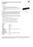
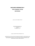
1
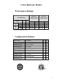
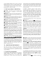
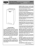
Installation & Operating Instructions Engineering Specifications Hydronic GW 240 thru 360 Series TABLE OF CONTENTS Section Title Page I. Ultra Hydronic Models A. Performance Ratings B. Configuration Options 2 II. Introduction to ECONAR Heat Pumps 3 III. Hydronic Heat Pump Applications A. Radiant Floor Heating B. Fan Coils C. Baseboard Heating D. Other Applications 4 IV. Unit Sizing A. Building Heat Loss / Heat Gain B. Ground Sources and Design Water Temperatures C. Hydronic-Side Heat Exchangers D. Temperature Limitations 5 V. Unit Location / Mounting 6 VI. Ground Source Design A. Ground Loop Applications 6 VII. Hydronic-Side System Design A. Storage Tanks B. Hydronic Side Circulators.lgkj C. Expansion Tanks D. Application Diagrams 7 VIII. Electrical Service 9 IX. 24 Volt Control Circuit A. Transformer B. Remote Hydronic Controls (Aquastat / Thermostat) C. Controller 9 X. Startup / Checkout 11 XI. Service and Lockout Lights 12 XII. Room Thermostat Operation 12 XIII. Performance Data 13 XIV. Physical Dimensions 15 XV. Electrical Data 15 XVI. Wiring 16 XVII. Correctional Factors 18 XVIII. Troubleshooting Guide for Lockout Conditions 19 XIX. Troubleshooting Guide for Unit Operation 20 XX.. Additional Figures, Tables, and Appendices 22 1 I. Ultra Hydronic Models Performance Ratings Ground Loop MODELS GW 2400 GW 3600 st 1 Stage 2nd Stage 1st Stage 2nd Stage HEATING COOLING 2nd Stage: 32°F EWT 1st Stage: 41°F EWT 2nd Stage: 77°F EWT 1st Stage: 68°F EWT 104ºF Hyd EWT 53.6ºF Hyd EWT Hyd GPM Ground GPM BTU/hr COP BTU/hr EER 40 40 54 54 60 60 78 78 130,600 222,400 189,750 318,000 4.3 3.3 4.3 3.3 142,000 240,700 191,700 316,500 21.8 15.2 19.6 14.6 * Tested using AHRI/ISO 13256-2 Configuration Options Model Suffix Description 240 360 GWxx0-x-Uxxx Standard, No Desuperheater • • GWxxx-2-Uxxx 208/230-3, 60Hz • • GWxxx-9-Uxxx 380-3, 60Hz ∗ ∗ GWxxx-3-Uxxx 460-3, 60Hz ∗ ∗ GWxxx-A-Uxxx 200/220 -3, 50Hz ∗ ∗ GWxxx-B-Uxxx 380-3, 50Hz ∗ ∗ GWxxx-C-Uxxx 575-3, 60Hz ∗ ∗ GWxxx-x-Ux0x Standard Hydronic • • GWxxx-x-UxTx Staged Tandem Compressor • • 2 II. INTRODUCTION TO ECONAR HEAT PUMPS Enertech Global, LLC, is home to ECONAR geothermal heat pumps, a brand that has been in Minnesota for over twenty years. The cold winter climate has driven the design of ECONAR’s heating and cooling equipment to what is known as a "ColdClimate" geothermal heat pump. This cold climate technology focuses on maximizing the energy savings available in heating dominated regions without sacrificing comfort. Extremely efficient heating, cooling, dehumidification and optional domestic hot water heating are provided in one neatly packaged system. Enertech produces three types of ECONAR heat pumps: hydronic, which transfers energy from water to water; forced air, which transfers energy from water to air; and combination, which incorporates the hydronic heating unit into a forced air unit. Geothermal heat pumps get their name from the transfer of energy to and from the ground. The ground-coupled heat exchanger (geothermal loop) supplies the source energy for heating and absorbs the discharged energy from cooling. The system uses a compression cycle, much like your refrigerator, to collect the ground’s energy supplied by the sun and uses it to heat your home. Since the process only moves energy, and does not create it, the efficiencies are three to four times higher than most efficient fossil fuel systems. Safety and comfort are designed into every ECONAR geothermal heat pump. Since the system runs completely on electrical energy, the entire home can have the safety of being gas-free. The best engineering and quality control is in every heat pump. Proper application and correct installation will ensure excellent performance and customer satisfaction. The Enertech commitment to quality is written on the side of every heat pump built. Throughout the manufacturing process, the technicians who assemble each unit sign their names to the quality assurance label after completing their inspections. As a final quality test, every unit goes through a full run-test where the performance and operation is verified in both the heating and cooling modes. No other manufacturer goes as far as to run a full performance check to ensure system quality. This guide discusses the Ultra hydronic unit. The Ultra uses R-410A refrigerant, which is environmentally friendly to the earth’s protective ozone layer. WARNING – Service of refrigerant-based equipment can be hazardous due to elevated system pressures and hazardous voltages. Only trained and qualified personnel should install, repair or service. The installer is responsible to ensure that all local electrical, plumbing, heating and air conditioning codes are followed. WARNING – ELECTRICAL SHOCK CAN CAUSE PERSONAL INJURY OR DEATH. Disconnect all power supplies before installing or servicing electrical devices. Only trained and qualified personnel should install, repair or service this equipment. WARNING –Verify refrigerant type before servicing. The nameplate on the heat pump identifies the type and the amount of refrigerant. All refrigerant removed from these units must be reclaimed by following accepted industry and agency procedures. CAUTION – Ground and hydronic loops must be freeze protected. Insufficient amounts of antifreeze may cause severe damage and may void warranty. The hydronic loop antifreeze must be non-flammable. Never operate with ground or hydronic loop flow rates less than specified. Continuous operation at low flow rates, or no flow, may cause severe damage and may void warranty. COMMON ACRONYMS DHW dP EWT GPM/gpm Ground Loop GTF HP LWT LP P/T VA Domestic Hot Water Pressure Differential Entering Water Temperature Gallons per Minute Also known as Closed Loop GeoThermal Transfer Fluid High Pressure Leaving Water Temperature Low Pressure Pressure/Temperature Volt Amperes III. HYDRONIC HEAT PUMP APPLICATIONS A. Radiant Floor Heating Radiant floor heat tubing is probably the most popular form of hydronic heating. It provides excellent comfort and very high efficiencies by supplying low temperature fluid to the floor slab and keeping the heat concentrated evenly near the floor. Radiant floor systems heat the occupants and surfaces directly with comfortable radiant energy. In contrast, forced air heating moves air around the building, which can create temperature stratification, drafts, and air rising to the ceiling. Remember that hot air rises, radiant energy does not. Radiant floor heating usually consists of 1/2 inch plastic tubing (PEX) approximately one linear foot of pipe per square foot of floor space. This value is doubled for one pass along the outside walls to concentrate more heat in that area. The tubing is generally laid into the concrete slab floor of the building. New construction techniques have also made installation into wood floors and suspended floors possible. The amount and spacing of the tubing is sized to meet the heating load of the space at a certain fluid temperature in the tubing. To optimize efficiency and capacity, the fluid temperature in the tubing should be 3 maintained as low as comfortably possible. The type of floor covering and the spacing of the pipe in the floor have the greatest effect on operating fluid temperature. Table 1 gives a rough estimate of expected operating temperatures for specific floor coverings: Table 1 – Expected Operating Floor Temps Floor Covering Temp (oF) Carpeting 115 Tile/Linoleum/Hard Wood 100 Concrete/Quarry Tile - Residential 85 Concrete/Quarry Tile - Commercial 70 Enertech designs its ECONAR hydronic heat pumps using a 115oF leaving water temperature (LWT) design point. This LWT is the ideal maximum fluid temperature for radiant floor systems. Higher operating temperatures would result in an uncomfortable hot feeling in the conditioned space. In fact, boilers connected to radiant floor heating systems must be restricted to a 115oF maximum temperature by mixing valves or other control devices. Suppliers of radiant floor heat exchanger tubing can help size the length of pipe and fluid temperature required for specific radiant floor heat exchanger applications. Be sure to include two inches of polystyrene insulation under the slab and two to four inches around the perimeter down to a four-foot depth. This insulation reduces the heat loss to the ground and decreases the response time of the heating system. Insulation is as important in radiant floor heating as it is in other methods of heating. Poorly insulated buildings can result in higher floor temperatures needed to heat the building, which could exceed the level of human comfort. Night setback controls are not recommended on radiant floor systems due to the slow response time of the slab. Radiant floor systems are not usually recommended for cooling, since poor dehumidification and cold/clammy floors may result. To provide cooling to a radiant floor heating installation, the installation of an ECONAR FC fan coil unit is recommended.. B. Fan Coils Fan coils, such as the ECONAR FC series, can be used with ECONAR hydronic heat pumps in the heating and cooling mode. In many cases, radiant floor heating and fan coil cooling are used together. Fan coils also provide dehumidification in the cooling mode, and the rate of dehumidification can be adjusted by selection of the fan coil operating temperature. Many different sizes and configurations of fan coils are available, making them very flexible to each particular application. Valence heating and cooling systems, which use natural convection to move air, can also be very versatile. Important – Fan coil units for cooling must have a condensate pan; and if accidental water discharge could cause property damage, there must also be a drained drain pan under the unit. Fan coils are sized for capacity at specific water flow rate and temperature combinations. Sizing also depends on air temperatures, air flow rates (which remain constant based on fan speed selection and static pressure differential), and humidity conditions. The fan coils are then matched to the heat pump at a common system flow rate and operating temperature to provide the overall system capacity to a space load. High static pressure fan coils have recently come onto the market, which work well with ECONAR hydronic heat pumps. These systems provide heating and cooling for houses without ductwork. They use a high static pressure blower to supply air through small tubes, which run through chaseways to the living space. The blower passes air though a water-to-air coil that is coupled to a hydronic heat pump to provide heating and cooling. These systems work nicely on retrofit applications where ductwork isn't available or wanted. C. Baseboard Heating Another application of hydronic heating is finned tube baseboard heating. This is the same tubing used with boilers with the major difference being that the discharge temperature of a geothermal heat pump is much lower than a boiler. The heat pump system must be sized at 115oF maximum hydronic LWT to maintain efficiency. Standard 3/4" finned tube baseboard conductors have approximately 200 Btuh/ft at 115oF hydronic LWT. There have been successful installations using baseboard as supplemental heating, and many other factors must be considered, such as sufficient perimeter area in the conditioned space to allow for the required amount of baseboard. Suppliers of baseboard radiators can help size the amount of baseboard and fluid temperature required for specific applications. Cast iron radiators have been used successfully. When rated for an output of 70 Btuh/square inch at a 115ºF hydronic LWT, they work well with geothermal systems. Although the radiator may be rated at 130oF, the system could still operate at the maximum 115oF LWT of the water-to-water heat pump. D. Other Applications Open loop applications such as outdoor swimming pools, hot tubs, whirlpools, tank heating, etc. are easily sized based on heat exchanger operating temperature and flow. In many instances, sizing the heat pump to these applications comes down to recovery time. A larger heat pump (within reason to avoid short cycling) will provide faster system recovery. Important – An intermediate nickel/stainless plate heat exchanger (as shown in Figure 1) between the heat pump 4 hydronic loop and the open system is required when corrosive fluid is used in the open loop; especially on swimming pools where pH imbalance can damage the heat pump. Note: Expect the operating temperature of an indirect coupled application to be 10oF below the LWT of the heat pump. Other forms of closed loop systems such as indoor swimming pools, pretreated fresh air systems, snow melt systems, and valance heating/cooling systems are also very common with hydronic heat pumps. The sizing of the heat pump to these systems is more precise, and information from those system manufacturers is required. IV. UNIT SIZING Selecting the unit capacity of a hydronic geothermal heat pump requires four things: A) Building Heat Loss / Heat Gain. B) Ground Sources and Design Water Temperatures. C) Hydronic-Side Operating Temperatures. D) Temperature Limitations A. Building Heat Loss / Heat Gain The space load must be estimated accurately for any successful HVAC installation. There are many guides or computer programs available for estimating heat loss and gain, including the Enertech Geothermal Heat Pump Handbook, Manual J, and others. After the heat loss and gain analysis is completed, Entering Water Temperatures (EWT’s) are established, and hydronic-side heating conditions are determined. The heat pump can now be selected using the hydronic heat pump data found in the Engineering Specifications. Choose the capacity of the heat pump based on both heating and cooling loads. B. Ground-Sources and Design Water Temperatures ECONAR Engineering Specifications provide capacities at different loop water temperatures and hydronic leaving water temperatures. Note: Table 2 shows the water-flow (GPM) requirements and water-flow pressure differential (dP) for the heat exchanger, and Table 3 shows the dP multiplier for various levels of freeze protection. Table 2 – Ground-Side Flow Rate Requirements Series Flow (gpm) dP* (psig) 60 5.6 GW240 78 6.0 GW360 * dP (psig) heat exchanger pressure drops are for pure water. Note: dP values are for standard heat exchanger configurations. Cupro Nickel heat exchanger configurations for Ground Water applications have higher dP. Table 3 – Heat Exchanger Pressure Differential (dP) Correction Factors for Freeze Protection (Typical) AntiFreeze Percent Volume (1) GTF 50% GTF Propylene 20% Glycol 25% (1) Freeze Level o 12 F 18oF 15oF dP Multiplier 25oF 35oF 90oF 110oF 125% 123% N/a N/a 136% 133% 118% 114% 145% 142% N/a N/a GTF = GeoThermal Transfer Fluid. 60% water, 40% methanol. 1. Ground Loop Systems (see Figure 2) Loop systems use high-density polyethylene pipe buried underground to supply a tempered water solution back to the heat pump. Loops operate at higher flow rates than ground water systems because the loop Entering Water Temperature (EWT) is lower. EWT affects the capacity of the unit in the heating mode, and loops in cold climates are normally sized to supply a wintertime EWT to the heat pump down to 25oF. C. Hydronic-Side Heat Exchangers Hydronic-side heat exchangers discussed in section VI are designed to operate at a specific fluid supply temperature. This operating temperature will have to be supplied to the selected space conditioning heat exchanger by the hydronic heat pump. The manufacturers or suppliers of the hydronicside heat exchangers publish the capacity of their equipment at different operating temperatures and fluid flow rates, and these capacities and operating temperatures are required to select the heat pump to be used in the system. When selecting the heat pump, choose a unit that will supply the necessary heating or cooling capacity at the minimum and maximum hydronic loop temperature conditions, respectively. Example; if a fan coil system requires 35000 Btu/hr to cool a space with 45oF water temperature entering the water-to-air fan coil, a GW47x Ultra heat pump is required to handle the cooling load. If an intermediate heat exchanger is used between the storage tanks as pictured in Figure 1, expect a 10oF operating temperature difference between the two tanks. For example, if the direct-coupled storage tank is at 110oF, expect the maximum operating temperature of the indirectcoupled tank connected through an intermediate heat exchanger to be 100oF. D. Temperature Limitations Be aware of the operating range of the geothermal system when sizing the particular heat pump to avoid premature equipment failure. Operating outside of these limitations may cause severe damage to the equipment and may void warranty. CAUTIONS: 5 • The acceptable hydronic LWT is 70 F to 115 F for o o o o heating and 35 F to 50 F for cooling. Hydronic EWT should remain above 50oF to avoid low-pressure lockouts. o o • The acceptable Ground Loop EWT is 25 F to 50 F for o o heating and 50 F to 100 F for cooling. V. UNIT LOCATION / MOUNTING CAUTION – Units must be kept in an upright position during transportation or installation, or severe internal damage may occur. Important – To ensure easy removal and replacement of access panels, leave panels secured in place until the unit is set in place and leveled. Important – Locate the unit in an indoor area where the ambient temperature will remain above 45oF. Service is done primarily from the front. Top and rear access is desirable and should be provided when possible. Important – A field installed drain pan is required under the entire unit where accidental water discharge could damage surrounding floors, walls or ceilings. CAUTION – Do not use this unit during construction. Dust and debris may quickly contaminate electrical and mechanical components; resulting in damage. CAUTION – Before driving screws into the cabinet, check on the inside of the unit to ensure the screw will not damage electrical, water, or refrigeration lines. Important – Units must be mounted on a vibrationabsorbing pad slightly larger than the base to provide isolation between the unit and the floor. Water supply pumps should not be hard plumbed directly to the unit with copper pipe; this could transfer vibration from the water pump to the refrigeration circuit, causing a resonating sound. Hard plumbing must be isolated from building structures that could transfer vibration from the unit through the piping to the living space. CAUTION – Always use plastic male fittings into plastic female or into metal female fittings. Never use metal male fittings into plastic female fittings. On metal-to-metal fittings; use pipe thread compound, do not use pipe thread tape, hand tighten first, and then only tighten an additional ½ turn with a tool if necessary. On plastic fittings, always use 2 to 3 wraps of pipe thread tape, do not use pipe thread compound, hand tighten first, and then only tighten an additional ½ turn with a tool if necessary. Do not overtighten, or damage may occur. VI. GROUND SOURCE DESIGN Since water is the source of energy in the winter and the energy sink in the summer, a good water supply is possibly the most important requirement of a geothermal heat pump system installation. a. Ground Loop Installation A Ground Loop system circulates the same antifreeze solution through a closed system of high-density underground polyethylene pipe. As the solution passes through the pipe, it collects energy (in the heating mode) from the relatively warm surrounding soil through the pipe and into the relatively cold solution. The solution circulates to the heat pump, which transfers energy with the solution, and then the solution circulates back through the ground to extract more energy. The Ultra is designed to operate on either vertical or horizontal ground loop applications. Vertical loops are typically installed with a well drilling rig up to 200 feet deep, or more. Horizontal loops are installed with excavating or trenching equipment to a depth of about six to eight feet, depending on geographic location and length of pipe used. Loops must be sized properly for each particular geographic area, soil type, and individual capacity requirements. Contact Enertech Customer Support or a local installer for loop sizing requirements in your area. Typical winter operating EWT to the heat pump ranges from 25oF to 32oF. CAUTION – Ground Loops must be properly freeze protected. Insufficient amounts of antifreeze may result in a freeze rupture of the unit or can cause unit shutdown problems during cold weather operation. Propylene glycol and Geothermal Transfer Fluid (GTF) are common antifreeze solutions. GTF is methanol-based antifreeze and should be mixed 50% with water to achieve freeze protection of 12oF. Propylene glycol antifreeze solution should be mixed 25% with water to obtain a 15oF freeze protection. Important – Do not mix more than 25% propylene glycol with water in an attempt to achieve lower than 15oF freeze protection, since more concentrated mixtures of propylene glycol become too viscous at low temperatures and cannot be pumped through the earth loop. Horizontal loops typically use GTF, and vertical loops typically use propylene glycol. Note – Always check State and Local codes for any special requirements on antifreeze solutions. CAUTION – Never operate with flow rates less than specified. Low flow rates, or no flow, may cause the unit to shut down on a pressure lockout or may cause a freeze rupture of the heat exchanger. Important – Figure 2 shows that Pressure/Temperature (P/T) ports must be installed in the entering and leaving water lines of the heat pump. A thermometer can be inserted into the P/T ports to check entering and leaving water temperatures. A pressure gauge can also be inserted into these P/T ports to determine the pressure differential between the entering and leaving water. This pressure differential can then be compared to the specification data on each particular heat pump to confirm the proper flow rate of the system. An individually-sized Enertech flow center can supply pumping requirements for the Ground Loop fluid, and can also be used to purge the loop system. Note – Refer to instructions included with the flow center for properly purging the ground loop. Important – the pump must be installed to supply fluid 6 into the heat pump. Filling and purging a loop system are very important steps to ensure proper heat pump operation. Each loop must be purged with enough flow to ensure two feet per second flow rate in each circuit in the loop. This normally requires a 1½ to 3 HP high-head pump to circulate fluid through the loop to remove all the air out of the loop. Allow the pump to run 10 to 15 minutes after the last air bubbles have been removed. After purging is completed, add the calculated proper amount of antifreeze to give a 12oF to 15oF freeze protection. After antifreeze has been installed and thoroughly circulated, it should be measured with a hydrometer, refractometer or any other device to determine the actual freezing point of the solution. The purge pump can be used to pressurize the system for a final static pressure of 30-40 psig after the loop pipe has had enough time to stretch. In order to achieve the 30 to 40 psig final pressure, the loop may need to be initially pressurized to 60-65 psig. This static pressure may vary 10 psig from heating to cooling season, but the pressure should always remain above 20 psig, so circulation pumps do not cavitate or pull air into the system. Contact your local installer, distributor or factory representative for more information. VII. HYDRONIC-SIDE SYSTEM DESIGN This section deals with some common practices used when coupling the ECONAR Ultra hydronic heat pumps to the space conditioning heat exchanger. There are so many possible applications for hydronic systems that they cannot all be covered in this text. Hopefully these ideas can help in many of your system designs. Note – Actual systems must be constructed to all appropriate codes and according to accepted plumbing practices. Caution – Always use copper pipe on the hydronic side of the system. Important – Pressure/Temperature port fittings must be installed in the entering and leaving hydronic lines of the heat pump. A. Storage Tanks Important – The heat pump must be coupled to the space conditioning system through a water storage tank. Important – The guideline for the active amount of fluid circulating between the heat pump and the storage tank is 10 gallons of fluid for each ton of hydronic heat pump capacity (Example, 50 gallons minimum for a 5-ton unit. If the fluid only circulates through half of the storage tank, then that half of the storage tank must contain the minimum 10 gallons per ton.). A properly sized storage tank eliminates many problems with multiple zone hydronic systems. These problems include excessive leaving water temperature if a single zone cannot dissipate heat quickly enough and hydronic flow reduction through the heat pump when only one zone is calling. This may occur because the hydronic circulating pump is normally sized to provide the heat pump’s required flow with all zones calling. In applications that use multiple smaller zones, storage tanks absorb the relatively large amount of energy supplied by the heat pump in order to provide longer run times and less compressor cycling for the heat pump. Storage tanks also serve to dispense energy in small amounts so that the conditioned zones have time to absorb heat without requiring high discharge water temperatures. (The only instance where a storage tanks is not required is when the heat pump is coupled to a large heat exchanger containing the recommended amount of fluid capable of absorbing the entire capacity of the heat pump.) Insulated water heaters are commonly used for storage tanks. Note – Always check local codes to ensure water heaters can be used as storage tanks. Using the electric elements in the tank as a secondary heat source to the heat pump is appealing in some applications, but special Listing Agency Certifications may be required by many local codes. Specially listed water heaters are available. While all hot water tanks are insulated on the top and sides, many do not have insulation on the bottom. An insulated pad beneath uninsulated tanks will reduce energy loss to the floor. Important – The hydronic flow into the storage tank (particularly a water heater) must not be restricted. If the water heater has an internal diffuser “dip tube,” cut it off at approximately 12 inches into the tank. The tank temperature can be controlled with a simple Aquastat or a setpoint controller. The setpoint controller senses tank water temperature and outside air temperature to increase the tank temperature as the outside air becomes colder. This control scheme provides the highest heating efficiencies by requiring the lowest possible water temperature to heat the space. Setting the optimal design temperatures in the controller is difficult, and the simple Aquastat does have its advantages. To help in setpoint control, the following equation can be used: Reset Ratio = Design Water Temp – Indoor Design Temp Indoor Design Temp – Outdoor Design Temp B. Hydronic Side Circulators Hydronic circulator pumps transfer the energy supplied by ECONAR hydronic heat pumps to the water storage tank. Select a quiet operating pump with the ability to supply the required flow rate at the system pressure drop. The circulator supplying the heat pump must be placed in the water supply line into the unit to provide the best pump performance. Individual zone circulators must also be placed in the supply lines of the heat exchangers they serve. These pumps are often used as the on/off control mechanism for the zone they supply as shown in Figure 4. Zone valves are also commonly used for this purpose using a common pump as shown in Figure 5. Note – Select a common pump at the total flow of all the zones and the highest pressure drop of any one parallel 7 zone. Small Grundfos pumps (230 Vac) should be used as circulator pumps. These pumps are impedance protected and do not require additional fusing if powered directly from the heat pump. CAUTION – Never operate with hydronic flow rates less than specified. Low flow rates, or no flow, may cause the unit to shut down on a pressure lockout or may cause a freeze rupture of the heat exchanger. Circulator pumps must be sized to provide the required flow to a heat pump heat exchanger at its corresponding system pressure drop calculated from the pressure drop through the piping, plus the pressure drop of the water storage tank, and plus the pressure drop through the heat pump heat exchanger. Table 4 shows the hydronic waterflow requirements and pressure drop (dP), and Table 3 shows the dP multiplier for various levels of freeze protection. Use these tables for sizing the circulating pump between the hydronic side of the heat pump and a storage tank. Table 4 – Storage Tank Circulators Hyd. Loop Series Flow dP (gpm) (psig) 40 3.4 GW240 54 3.3 GW360 Grundfos Circulator * * *Size circulators for specific installations. Note: See Table 3, Heat Exchanger Pressure Differential (dP) Correction Factors for Freeze Protection. Table 4 represents the minimum pump size to supply the heat pump’s required hydronic side flow to a storage tank at the pressure drop of the heat pump and 30 feet of ¾” type K copper tubing (or a combination of approximately 20 feet with typical elbows and fittings) (2” pipe on 240 and 360 series). A common problem with circulator pumps is trapped air in the system. This air accumulates in the suction port of the circulator causing cavitation in the pump, which leads to premature pump failure and noisy operation. The air can be eliminated by completely purging the system or by placing an air separator in the plumbing lines. The entire system must be purged of air during initial installation and pressurized to a 10-25 psig static pressure to avoid air entering the system. This static pressure may fluctuate when going from the heating to cooling modes but should always remain above zero. If a leak in the system causes the static pressure to drop, the leak must be repaired to assure proper system operation. The hydronic side circulator supplying the heat pump should be controlled to run only when the compressor runs. If the pump is allowed to circulate cold water through the system during off cycles, the refrigerant in the heat pump will migrate to the hydronic side heat exchanger. This can cause heat pump starting problems (especially when this refrigerant migrates into the condenser). C. Circulation Fluid The fluid circulating through the hydronic side of the geothermal heat pump system is the transfer medium for the heating and cooling being supplied to the conditioned space. Selection of this fluid is very important. Water is the most readily available fluid but has the drawback of expansion during freezing which can damage the system. System operation in the cooling mode, extended power interruption to a structure, or disabling of an outside zone (such as a garage floor) provides the opportunity for freezing the circulating fluid. CAUTION – the hydronic side of the system must be freeze protected to reduce the risk of a freeze rupture of the unit. A propylene glycol based antifreeze (readily available through HVAC wholesalers) and water solution is recommended. A non-flammable antifreeze solution is recommended for use on any hydronic system where heat is being added to the system for structural heating purposes. Freeze protection for the hydronic side fluid down to 18oF (20% propylene glycol by volume in water) is recommended for most indoor applications. Forty percent propylene glycol in water (-5oF freeze protection) is recommended by radiant tube manufactures for snow melt applications to protect the tubing from expansion in outdoor applications. Using over 40% in hydronic side applications can cause pumping problems due to high viscosity. The water being added to the system should have 100-PPM grain hardness or less. If poor water conditions exist on the site, softened water is recommended, or acceptable water should be brought in. Bacteria or algae growth in the water is a possibility at the temperatures produced in the heating system and can cause buildup on hydronic side heat exchanger surfaces, reducing the efficiency of the system or causing the heat pump to run at higher head pressures and possibly lock out. A gallon of bleach or boiler system conditioner can reduce the possibility of growth and can clean up other components in the system. D. Expansion Tanks Expansion tanks must be used in the hydronic side of the water-to-water system to absorb the change in pressure of the closed system due to the change in temperature when heat is supplied to the system. Diaphragm-type expansion tanks should be used. EPDM diaphragm tanks are compatible with glycol-based antifreeze fluids (butyl rubber diaphragms will slowly dissolve with glycol-based antifreezes). Expansion tanks from 1 to 10 gallons are generally used with heat pump systems in residential and light commercial applications. Expansion tanks should be installed in the system near the suction of the circulator pump to maintain positive pressure at the circulator pump and reduce the highest working pressure of the system. A pressure gauge near the inlet of the expansion tank gives a good indication of how the system is operating. 8 be connected to the middle leg on the contactor. Pressure relief valves are required on hydronic applications. A 30 psig relief is adequate if the system is operated at 12 to 15 psig pressure. If a water heater is used for a storage tank, the 150 psig pressure relief may be acceptable (check local codes). E. Application Diagrams Figures 1 through 4 show the components of a hydronic heat pump system discussed above used in some common applications. These figures by no means represent all the possible hydronic heat pump applications, but they do show some important principals that can be applied to any system. VIII. ELECTRICAL SERVICE Note – Always refer to the inside of the electrical box cover for the correct wiring diagram, and always refer to the nameplate on the exterior of the cabinet for the correct electrical specifications. WARNING – ELECTRICAL SHOCK CAN CAUSE PERSONAL INJURY OR DEATH. Disconnect all power supplies before installing or servicing electrical devices. Only trained and qualified personnel should install, repair or service this equipment. WARNING – THE UNIT MUST BE PROPERLY GROUNDED! The main electrical service must be protected by a fuse or circuit breaker and be capable of providing the amperes required by the unit at nameplate voltage. All wiring must comply with the national electrical code and/or any local codes that may apply. Access to the line voltage contactor is through the knockouts provided on the side of the heat pump next to the front corner. Route EMT or flexible conduit with appropriate size and type of wire. Ensure adequate supply wiring to minimize the level of dimming lights during compressor startup on single-phase installations. Some dimming is normal, and a variety of start-assist accessories are available if dimming is objectionable. Important – some models already have a factory-installed start assist. Do not add additional start assists to those units. CAUTION – route field electrical wiring to avoid contact with electrically live bare metal parts inside the electrical box and to avoid contact with the surface of the factory-installed start assist (if provided). CAUTION – Three-phase units must be wired properly to ensure proper compressor rotation. Improper rotation may result in compressor damage. An electronic phase sequence indicator must be used to check supply-wiring phases. Also, the “Wild” leg of the three-phase power must Note – GW240 and 360 do not have an internal pump relay. A pump for the GW240 and 360, or a pump larger than 1/3 horsepower on any other unit, must be powered from a separate fused power supply and controlled through an isolation relay that has its 24Vac coil wired to the Y and X terminals. IX. 24 VOLT CONTROL CIRCUIT Note – Always refer to the inside of the electrical box cover for the correct wiring diagram. There are three basic sections of the low voltage circuit; transformer, remote hydronic controls, and controller. A. Transformer An internal transformer provides 24Vac for all control features of the heat pump. Even though the transformer is larger than the industry standard, it is in a warm electrical box and can be overloaded quickly. Table 5 shows the transformer usage. Table 5 – Transformer Usage (VA) Component Contactor Pump Relay Reversing Valve Controller 20-1038 Compressor Overload Contactor Pilot Relays Remote Hydronic Control Plug Accessory (PA) Total Transformer VA size 240 360 16 (2) 27 (2) N/A N/A 18 18 2 2 N/A 6 (2) 4 (2) 4 (2) 2 2 10 10 72VA 106VA 150 150 Important – If the system’s external controls require more than shown in Table 5, an external transformer and isolation relays should be used. In contrast, Figure 4 shows a fan coil system with its own power supply, which must interface to the heat pump to put the heat pump into the cooling mode. This can be accomplished by using the fan coil’s independent power supply to energize the coil of an isolation relay with contacts located in heat pump's control circuit. WARNING – GW240 and 360 use a large-capacity 24Vac Control Transformer, and field wiring to remote hydronic controls must be suitable for NEC Class 1. Important – Miswiring of 24Vac control voltage on system controls can result in transformer burnout. Important – Units with a dual voltage rating (example, 208/230) are factory-wired for the higher voltage (example, 230). If connected to a power supply having the lower voltage, change the wiring to the transformer primary to the correct lead; otherwise premature failure, or inability to 9 operate the control components may occur. system if zone valves were used instead of two pumps. B. Remote Hydronic Controls C. Controller The GW240, and 360 use tandem compressors (two connected together) configured as stage-controlled with separate Y and Y2 inputs with an adjustable time delay for the Y2-controlled contactor. Consult the instructions packaged with the remote hydronic controls for proper mounting and operation of the hydronic controls. The heat pump controller receives a signal from the remote hydronic control, initiates the correct sequence of operation for the heat pump, and performs the following functions: 1) Compressor Anti-Short Cycle 2) Compressor Control 3) Ground Loop Pump 4) Compressor Staging 5) Hydronic Circulator Pump Control 6) 4-Way Valve Control 7) Compressor Lockouts 8) System Diagnostics 9) 24Vac Fuse 10) Plug Accessory 11) Alarm Output 12) GW360 Compressor Overload Modules Important – If one remote hydronic control operates multiple heat pumps, the control wiring of the heat pumps must be isolated with isolation relays to avoid excessive voltages or overheating and premature failure of the control components. Power is supplied to the remote hydronic control from the R and X terminals on the heat pump terminal strip. A single-stage hydronic control (heating Aquastat) on a storage tank or a wall mounted thermostat may be all that is required for simple heat-only systems. The contact on the hydronic control closes and provides 24Vac to the Y terminal. When using a hydronic control, insert the temperature sensor approximately 1/3 of the way down into the storage tank. Set the hydronic control setpoint to 110115oF typical, and set the differential to 15oF to avoid short cycling. CAUTION – The setpoint of the hydronic control must limit the LWT from the heat pump to a maximum of 120oF to avoid premature failure of the compressor. A cooling hydronic control (Aquastat) can be mounted on the water supply line, as shown in Figure 4. This control acts as a low limit, which shuts the heat pump down when the cooling water reaches the setpoint (e.g. 45oF). Changeover from heating to cooling can be achieved in two ways: 1) a manual toggle switch to select the heating or the cooling hydronic control (Aquastat), or 2) a cooling thermostat which powers the coil of a single pole/double throw relay to select the heating hydronic control (normally closed contact) or the cooling hydronic control (normally open contact). Note – Always wire the system to shut down (Anti-shortcycle) between a heating and cooling mode changeover, or nuisance trip-outs could occur from changing modes “on the fly.” 1. Compressor Anti-Short Cycle An Anti-Short-Cycle (ASC) is a delay period between the time a compressor shuts down and when it is allowed to come on again. This protects the compressor and avoids nuisance lockouts for these two conditions; 1. A 70 to 130-second random time-out period occurs before a re-start after the last shutdown. 2. A 4-minute/25-second to 4-minute/45-second randomstart delay occurs immediately after power is applied to the heat pump. This occurs only after reapplying power to the unit. To reduce this timeout delay while servicing the unit, apply power, disconnect and reapply power very quickly to shorten the delay. 2. Compressor Control When 24Vac is applied to the Y terminal on the controller wiring block, the controller decides, based on lockout and anti-short-cycle periods, when to turn on the compressor contactor. The M1 output of the controller energizes the contactor(s) until 24Vac is removed from the Y terminal. 3. Ground Loop Pump / Ground Water Initiation On ground loop systems, a M1 output from the controller will energize the contactor to start the compressor and the ground loop pump. On ground water systems, the M1 output will also energize the ground water solenoid valve through the “Plug Accessory” connector. 4. Compressor Staging For Zoning applications, any number or types of thermostats, Aquastats, or switches can be used with an independent power supply (typically a 24-volt transformer) to activate specific zone controls. These zone controls are normally either a zone pump (Figure 4) or zone valves (Figure 5). End switches on the zone valves can be used to control a pump relay when the zone valve is open. The pump relay then activates a common pump, which supplies any number of zones. Example: the fan coil in Figure 4 could be supplied by the same pump as the radiant floor GW240 and 360 have staged compressors controlled with separate Y and Y2 inputs. The M1 output of the controller energizes the first compressor contactor and begins the time-out of the time delay (adjustable 10 to 1000 seconds; factory set at 10). After the time-out delay, a Y2 input can energize the 2nd compressor contactor. Note – Ensure there is always a delay time between the operation of the two compressors to avoid nuisance low-pressure lockouts. 10 The hydronic circulator pump is energized either directly with the compressor contactor through the internal pump relay (RP) and 3-pole terminal block (BP) or through an isolation relay having its 24Vac coil wired to the Y and X terminals. identified as “Fault Test” on the controller board and as DO on the wiring diagram. It is an isolated dry contract output (0.1 ohm resistance) that closes during a controller lockout and is intended for use as an input to a dial-out type of monitoring system. The maximum electrical rating is 2mA up to 30Vac or 50mA up to 40Vdc. 6. 4-Way Valve Control 11. GW360 Compressor Overload Modules When 24Vac is applied to the O terminal on the wiring block, the controller energizes its O output to provide 24Vac power to the reversing valve (VR) to switch the refrigerant circuit to the cooling mode. The GW360 has additional compressor overload modules mounted directly onto the compressor. 5. Hydronic Circulator Pump Control X. STARTUP / CHECKOUT 7. Compressor Lockouts The controller will lock out the compressor if either of the following switches open: 1) high-pressure 600 psig, 2) lowpressure 35 psig (previously 50) on ground loop or 60 psig on ground water, or 3) discharge refrigerant temperature (275ºF). A lockout condition means that the unit has shut itself down to protect itself, and will not come back on until power has been disconnected (via the circuit breaker) to the heat pump for one minute. Problems that could cause a lockout situation include: 1. Low water flow or extreme water temperatures 2. Cold ambient air temperature conditions 3. Internal heat pump operation problems. If a lockout condition exists, the heat pump should not be reset more than once; and a service technician should be called immediately. CAUTION – Repeated reset may cause severe damage to the system and may void warranty. The cause of the lockout must be determined and corrected. 8. System Diagnostics The controller is equipped with diagnostic LED lights that indicate the system status at any particular time. The lights indicate the following conditions: 1. 24 Volt system power GREEN 2. Fault or Lockout YELLOW 3. Anti-short-cycle mode RED If a room thermostat installed with the heat pump system has a lockout indicator, the controller will send a signal from L on the terminal strip to a LED on the thermostat to indicate a lockout condition. 9. 24 Vac Fuse The controller has a glass-cartridge fuse located on the circuit board adjacent to the 24Vac power connector. The green system power LED will be off if this fuse is open. A spare fuse is located in the saddle attached to the side of the 24Vac power connector, and the GW240 and 360 also have a miniature rocker-type circuit breaker located on the divider-wall in the electrical box. Note – Ensure the new fuse fits tightly in the fuse clips after replacement. 10. Alarm Output This output is a 2-position screw terminal connector Before applying power to the heat pump, check the following items: • Water supply plumbing to the heat pump is completed and operating. Manually open the water valve on well systems to check flow. Make sure all valves are open and air has been purged from a loop system. Never operate the system without correct water supply flow on either the ground side or the hydronic side. • All high voltage and all low voltage wiring is correct and checked out, including wire sizes, fuses and breakers. Set system to the “OFF” position. • Note – the heat pump is located in a warm area (above 45oF). (Starting the system with low ambient temperature conditions is more difficult and may cause low-pressure lockout.) Do not leave the area until the space is brought up to operating temperatures. • Hydronic side water temperatures are warm enough (50oF or above) to start in the heating mode. Apply power to the unit. A 4-minute/35-second delay on power-up is programmed into the controller before the compressor will operate. During this time, the pump relay will energize the hydronic side-circulating pump. Verify the flow rate and temperature of the hydronic side flow. The following steps will ensure the system is heating and cooling properly. After the initial time-out period, the red indicator light on the controller will shut off. The heat pump is now ready for operation. • Turn the heating setpoint to its highest temperature setting, and place the system to run in heating. The compressor should start 1 to 2 seconds later. If an electronic thermostat is used, it may cause its own compressor delay at this time, but the compressor will come on after the time-out period. • After 5 minutes of heating operation, check hydronicside return and supply water temperatures. A water temperature rise of 10oF to 15oF is normal (variation in water temperature and water flow rate can cause slight variations). Use a single pressure gauge to check the fluid pressure drop through the heat exchangers to ensure proper flow for the system. • Set the system to the “OFF” position. The compressor will shut down in 1 to 2 seconds. • Next, turn the setpoint to its lowest setting. Place the 11 system to run in cooling. The compressor will start after an anti-short-cycle period of 70 to 130 seconds from its last shutdown. The anti-short-cycle period is indicated by the red light on the controller. • After 5 minutes of cooling operation, check hydronic side return and supply water temperatures. A water temperature drop of 10oF to 15oF is normal (variation in water temperature and water flow can cause slight variations). Use a single pressure gauge to check the fluid pressure drop through the heat exchangers to ensure proper flow for the system. • Set the system and the setpoint for normal operation. • Instruct the owner on correct operation of the entire heat pump system. The unit is now operational. XI. SERVICE and LOCKOUT LIGHTS Properly installed, the ECONAR Ultra heat pump requires only minor maintenance, such as periodic cleaning of the ground water heat exchanger for heat pumps installed in ground-water applications. Setting up regular service checkups with your Enertech dealer could be considered. Any major problems with the heat pump system operation will be indicated on the lockout lights. CAUTION – During evacuation of refrigerant of a system not having antifreeze protection of either the ground-side or the hydronic-side, water in the unprotected heat exchanger must be removed or continuously flowing to avoid a potential heat exchanger failure caused by freeze rupture. Important – Always install a new filter/dryer after replacing a refrigeration component (compressor, etc.). The heat pump controller (and a room thermostat, if part of the system installation) will display a system lockout. If lockout occurs, follow the procedure below: 1) Determine and record which indicator lights on the Controller are illuminated. (Refer to Section XIV for more information on possible causes of Lockout Conditions.) 2) Check for correct water supply from the ground loop. 3) Check for correct water supply on the hydronic side. 4) Reset the system by disconnecting power at the circuit breaker for one minute and then reapplying. 5) If shutdown reoccurs, call your Enertech dealer. Do not continuously reset the lockout condition or serious damage may occur. Note – Improper fluid flows or incorrect antifreeze levels are the cause of almost all lockouts. XII. ROOM THERMOSTAT OPERATION Installations may include a wide variation of available electronic room thermostats, and most of them require to be configured by the Installer (according to the Installation Guide included with the thermostat) and checked out after being installed. Important – At a minimum: 1. Ensure the thermostat is set up for the “System Type” it is installed on. 2. Ensure the thermostat is configured for “Manual Heat/Cool Changeover.” 3. Change other Installer Settings only if necessary. 4. Remember to press “Done” to save the settings and to exit “Installer Setup.” 5. Run the system through all modes of operation in the thermostat instructions to ensure correct operation. If you have additional questions, please refer to the installation manual that was sent with the thermostat. 12 GW 2400 Heating Performance Data GROUND EWT o F GPM dP psig dP ft Hyd LWT o F 70 25 30 35 40 50 60 60 60 60 60 5.6 5.6 5.6 5.6 5.6 First Stage Second Stage Second Stage HYDRONIC FLOW - 40 GPM HYDRONIC FLOW - 40 GPM 3.4 PSIG dP, 7.9 FT dP 3.4 PSIG dP, 7.9 FT dP REFRIGERANT PRESSURE TEMP DROP CAP kBTUh PWR kW COP HE kBTUh TEMP DROP CAP kBTUh PWR kW COP HE kBTUh 5.9 117.4 5.3 6.5 99.4 10.6 211.6 10.6 5.8 175.4 85 5.7 113.4 6.7 5.0 90.6 10.4 204.4 13.4 4.5 162.1 100 5.5 109.3 8.1 4.0 81.8 10.2 197.2 16.3 3.6 148.7 115 5.3 105.3 9.5 3.3 73.0 10.0 190.0 19.1 3.0 135.4 70 6.3 126.4 5.4 6.9 108.2 11.3 225.8 10.8 6.2 189.1 85 6.1 121.7 6.7 5.3 98.7 11.1 218.9 13.6 4.7 174.8 100 5.8 116.9 8.1 4.2 89.3 10.8 211.9 16.4 3.8 160.4 115 5.6 112.2 9.5 3.5 79.9 10.6 205.0 19.2 3.2 146.1 70 6.8 135.4 5.4 7.3 116.9 12.0 240.0 10.9 6.5 202.8 85 6.5 130.0 6.8 5.6 106.9 11.7 231.7 13.7 5.0 187.5 100 6.2 124.6 8.1 4.5 96.8 11.4 223.3 16.5 4.0 172.1 115 6.0 119.1 9.5 3.7 86.7 11.1 215.0 19.2 3.4 156.8 70 7.2 144.4 5.5 7.7 125.7 12.7 254.2 11.1 6.7 216.5 13.0 Suction Pressure 60 - 70 13.0 65 - 75 13.0 70 - 80 85 6.9 138.3 6.8 5.9 115.0 12.4 247.3 13.8 5.3 200.1 100 6.6 132.2 8.2 4.7 104.3 12.0 240.3 16.5 4.3 183.8 115 6.3 126.1 9.5 3.9 93.6 11.7 233.3 19.3 3.5 167.4 70 8.1 162.3 5.6 8.5 143.3 14.1 282.7 11.4 7.3 243.9 85 7.7 154.8 6.9 6.6 131.3 13.7 273.5 14.1 5.7 225.5 100 7.4 147.4 8.2 5.2 119.3 13.2 264.5 16.7 4.6 207.2 115 7.0 140.0 9.6 4.3 107.4 12.8 255.0 19.4 3.8 188.8 13.0 75 - 90 13.0 85 - 105 Head Pressure 195 215 255 275 315 335 375 395 195 215 255 275 315 335 375 395 200 220 260 280 320 340 380 400 200 220 265 285 325 345 385 405 205 225 265 285 330 350 390 410 GW 2400 Cooling Performance Data GROUND Hyd LWT o F EWT o F 50 70 80 90 100 GPM 60 60 60 60 60 dP psig 5.6 5.6 5.6 5.6 5.6 dP ft 13.0 13.0 13.0 13.0 13.0 First Stage Second Stage Second Stage HYDRONIC FLOW - 40 GPM HYDRONIC FLOW - 40 GPM 3.4 PSIG dP, 7.9 FT dP 3.4 PSIG dP, 7.9 FT dP REFRIGERANT PRESSURE TEMP DROP CAP kBTUh PWR kW EER HR kBTUh TEMP DROP CAP kBTUh PWR kW EER HR kBTUh Suction Pressure 35 6.3 126.3 4.4 28.6 141.4 11.1 222.6 9.6 23.3 255.3 80 - 90 40 6.7 133.9 4.5 29.8 149.2 11.7 234.9 9.6 23.7 268.7 85 - 95 45 7.1 141.4 4.5 31.1 157.0 12.4 247.2 10.2 24.2 282.1 85 - 95 50 7.5 149.0 4.6 32.3 164.7 13.0 259.5 10.6 24.6 295.5 90 - 100 35 5.7 113.7 6.0 19.1 134.0 10.5 209.4 12.9 16.2 252.4 85 - 95 40 6.1 122.4 6.0 20.3 142.9 11.2 223.7 13.2 16.9 268.9 90 - 100 45 6.5 131.0 6.1 21.6 151.7 11.9 238.0 13.6 17.5 284.4 90 - 100 50 7.0 139.6 6.1 2.8 160.5 12.6 252.3 13.9 18.1 299.8 95 - 105 35 5.4 107.4 6.7 16.0 130.4 10.1 202.8 14.6 13.9 252.5 85 - 105 40 5.8 116.6 6.8 17.2 139.7 10.9 218.1 14.9 14.6 269.0 90 - 110 45 6.3 125.8 6.8 18.4 149.1 11.7 233.5 15.3 15.3 285.5 90 - 100 50 6.7 134.9 6.9 19.6 158.4 12.4 248.8 15.6 15.9 302.1 95 - 105 35 5.1 101.1 7.5 13.5 126.7 9.8 196.2 16.2 12.1 251.6 90 - 100 40 5.5 110.8 7.5 14.7 136.6 10.6 212.6 16.6 12.8 269.1 95 - 105 45 6.0 120.5 7.6 15.9 146.4 11.4 228.9 16.9 13.5 286.7 95 - 105 50 6.5 130.2 7.6 17.0 156.3 12.3 245.2 17.3 14.2 304.2 100 - 110 35 4.7 94.9 8.3 11.5 123.0 9.5 189.6 17.9 10.6 250.7 90 - 100 40 5.3 105.1 8.3 12.6 133.4 10.3 207.0 18.3 11.3 269.3 95 - 105 45 5.8 115.3 8.4 13.8 143.8 11.2 224.3 18.6 12.0 287.8 95 - 105 50 6.3 125.5 8.4 14.9 154.2 12.1 241.6 19.0 12.7 306.4 100 - 110 Head Pressure 175-205 260 290 290 325 325 365 370 405 13 GW 3600 Heating Performance Data GROUND EWT o F 25 30 35 40 50 GPM 78 78 78 78 78 dP psig 6.0 6.0 6.0 6.0 6.0 dP ft Hyd LWT o F First Stage Second Stage Second Stage HYDRONIC FLOW - 54 GPM HYDRONIC FLOW - 54 GPM 3.3 PSIG dP, 7.6 FT dP 3.3 PSIG dP, 7.6 FT dP REFRIGERANT PRESSURE TEMP DROP CAP kBTUh PWR kW COP HE kBTUh TEMP DROP CAP kBTUh PWR kW COP HE kBTUh 70 6.9 187.6 9.2 5.9 156.0 12.6 331.3 16.4 5.9 275.4 85 6.6 177.5 10.8 4.8 140.8 11.9 313.4 20.1 4.6 244.8 100 6.2 167.4 12.3 4.0 125.5 11.2 295.4 23.8 3.6 214.1 115 5.8 157.2 13.8 3.3 110.2 10.5 277.4 27.5 3.0 183.5 70 7.4 199.7 9.3 6.3 167.9 13.5 350.4 16.8 6.1 293.2 13.8 Suction Pressure 50 - 70 85 7.0 189.3 10.8 5.1 152.2 12.8 333.8 20.4 4.8 264.1 100 6.6 178.9 12.3 4.2 136.7 12.1 317.1 24.1 3.9 235.0 115 6.2 168.5 13.9 3.5 121.1 11.3 300.5 27.7 3.2 205.9 70 7.8 211.8 9.4 6.6 179.8 14.5 369.4 17.1 6.3 310.9 13.8 55 - 75 85 7.4 201.1 10.0 5.4 163.9 13.7 354.1 20.7 5.0 283.4 100 7.1 190.4 12.4 4.5 148.0 13.0 338.9 24.3 4.1 255.8 115 6.7 179.7 14.0 3.8 132.0 12.2 323.6 28.0 3.4 228.3 70 8.3 223.9 9.4 6.9 191.7 15.4 388.4 17.5 6.5 328.7 85 7.9 212.9 11.0 5.7 175.4 14.6 374.5 21.1 5.2 302.7 100 7.5 201.9 12.5 4.7 159.2 13.9 360.7 24.6 4.3 276.7 115 7.1 190.9 14.1 4.0 142.9 13.1 346.8 28.2 3.6 250.6 70 9.2 248.0 9.6 7.6 215.4 17.2 426.5 18.2 6.8 364.3 13.8 57 - 80 13.8 60 - 85 85 8.8 236.5 11.1 6.2 198.5 16.4 415.3 21.7 5.6 341.3 100 8.3 224.9 12.7 5.2 181.6 15.6 404.2 25.1 4.7 318.4 115 7.9 213.3 14.3 4.4 164.7 14.8 393.0 28.6 4.0 295.4 13.8 65 - 98 Head Pressure 195 215 260 280 320 340 380 400 195 215 260 280 320 340 383 403 195 215 260 280 320 340 385 405 195 215 260 280 320 340 385 405 195 215 260 280 320 340 390 410 GW 3600 Cooling Performance Data GROUND Hyd LWT o F EWT o F 50 70 80 90 100 GPM 78 78 78 78 78 dP psig 6.0 6.0 6.0 6.0 6.0 dP ft 13.8 13.8 13.8 13.8 13.8 First Stage Second Stage Second Stage HYDRONIC FLOW - 54 GPM HYDRONIC FLOW - 54 GPM 3.3 PSIG dP, 7.6 FT dP 3.3 PSIG dP, 7.6 FT dP REFRIGERANT PRESSURE TEMP DROP CAP kBTUh PWR kW EER HR kBTUh TEMP DROP CAP kBTUh PWR kW EER HR kBTUh Suction Pressure 35 6.6 182.0 7.8 23.3 208.6 11.1 299.1 15.3 19.5 351.4 62 - 72 40 7.4 192.6 7.8 24.6 219.2 12.5 318.3 15.4 20.7 370.8 66 - 76 45 8.3 203.3 7.8 26.0 229.8 13.8 337.4 15.5 21.8 390.2 70 - 80 50 9.1 213.7 7.8 27.3 240.4 15.2 356.5 15.6 22.9 409.5 75 - 85 35 6.1 170.4 9.9 17.3 204.0 10.6 290.6 20.0 14.5 359.0 63 - 73 40 6.8 180.7 9.9 18.2 214.5 11.7 306.7 20.1 15.2 375.4 68 - 78 45 7.5 191.1 10.0 19.2 225.1 12.8 322.7 20.2 15.9 391.8 72 - 82 50 8.1 201.4 10.0 20.1 235.6 13.9 338.8 20.3 16.7 408.2 77 - 87 35 5.8 164.6 10.9 15.1 201.7 10.4 286.3 22.4 12.8 362.8 64 - 74 40 6.4 174.8 11.0 15.9 212.2 11.4 300.9 22.5 13.4 377.7 69 - 79 45 7.1 185.0 11.1 16.7 222.7 12.3 315.4 22.6 13.9 392.6 73 - 83 50 7.7 195.2 11.1 17.5 233.2 13.3 329.9 22.7 14.5 407.5 77 - 87 35 5.5 158.8 11.9 13.3 199.4 10.2 282.0 24.8 11.4 366.5 65 - 75 40 6.1 168.9 12.0 14.1 209.9 11.0 295.1 24.9 11.9 380.0 69 - 79 45 6.7 179.0 12.1 14.8 220.3 11.8 308.1 25.0 12.3 393.4 74 - 84 50 7.2 189.0 12.2 15.4 230.8 12.7 321.1 25.1 12.8 406.9 78- 88 35 5.3 153.0 12.9 11.8 197.1 9.9 277.8 27.1 10.2 370.3 66 - 76 40 5.8 163.0 13.1 12.5 207.5 10.6 289.3 27.3 10.6 382.3 70 - 80 45 6.3 172.9 13.2 13.1 218.0 11.3 300.8 27.4 11.0 394.2 75 - 85 50 6.7 182.9 13.3 13.7 228.4 12.0 312.3 27.5 11.3 406.2 79 - 89 Head Pressure 165 196 250 280 290 325 335 360 380 410 14 XIV. Physical Dimensions – Ultra Hydronic Models GW 240 and 360 Series 36.7" 30" 0.88" Dia. Knockouts 51" Access Panel Out to Ground Loop Out to Hydronic Load In from Ground Loop In from Hydronic Load Ground Model *GW240 Hydronic Inlet Outlet Inlet Outlet Desuperheater 2.0 MPT 2.0 MPT 2.0 MPT 2.0 MPT Not Available 2.0 MPT 2.0 MPT 2.0 MPT 2.0 MPT Not Available *GW360 *Note: GW 77-110 have a 1-1/2” support rails. This height is in addition to the height shown in the drawing. *Note: GW240 and GW360 have a 2” support rail. This height is in addition to the height shown in the drawing. Physical Data Ultra 240 Compressor Expansion Device Desuperheater Pump Transformer (VA) Weight (lbs) 360 Compliant Scroll Thermostatic 1/150 HP None 50 or 55 150 800 1010 XV. Electrical Data (all HCAR-type circuit breaker per NEC) (GD, GW) – (*HCAR-type circuit breaker per NEC) Model 2400 3600 Voltage Phase Frequency (Hz) 208/230-3, 60 460-3, 60 380-3, 60 200/220-3, 50Hz 380-3, 50Hz 575-3, 60 208/230-3, 60 460-3, 60 380-3, 60 200/220-3, 50Hz 380-3, 50Hz 575-3, 60 Compressor RLA LRA 33.3 x 2 239 x 2 17.9 x 2 125 x 2 23.7 x 2 145 x 2 34.6 x 2 239 x 2 17.9 x 2 118 x 2 12.8 x 2 80 x 2 55.8 x 2 340 x 2 26.9 x 2 173 x 2 34.0 x 2 196 x 2 50.6 x 2 325 x 2 25.0 x 2 173 x 2 23.7 x 2 132 x 2 Hydronic Pump HP FLA ------------------------- Without PumpPAK Total Min. Max FLA Amp. Fuse 66.6 74.9 105 35.8 40.3 55 47.4 53.3 75 69.2 77.9 110 35.8 40.3 55 25.6 28.8 40 111.6 125.6 180 53.8 60.5 85 68.0 76.5 110 101.2 113.9 160 50.0 56.3 80 47.4 53.3 75 PumpPAK HP FLA ------------------------- Total FLA ------------- With PumpPAK Min. Max Amp. Fuse ------------------------- 15 XVI. Wiring Diagram – Ultra Hydronic Models [GW240x-x-UxTx] Hydronic Control System NEC Class 1 Wiring (24Vac) Yel T2 T1 Y2 NC NO CB5 PWR SP E R G O Y W2 L X J1 F1 R Equipment Ground Yel Red X2 Red Power 24V Transf WHT Power Block H2, 208V Yel X1 Blu X J2 BLK H1, BLK BLU Blu RED X Red J3 B L K Yel R X Blu Yel G X LP/ FP HP M1 M1 Blu Yel RI B L K Red Blu Blk Blk DT Blk M2 2nd-Stage Relay Blu O X R E D Blu Blu Controller B L U Yel ASC PA DT 3-Phase COM Yel DO TD B L U B L K R E D B L U R E D Red Blu Blu HP VR L2 L2 LP / FP L1 10VA Maximum External Connected Load (24Vac) Hydronic Heat Pump Electrical Diagram Rev C, 07/08 80-0049 L1 L3 COMPRESSOR 2 COMPRESSOR 1 Factory Low Voltage Factory Line Voltage Field Line Voltage Field Class 1 Wiring CB5 Circuit Breaker, 5A DO DT F1 FP HP Dry Contact Output Discharge Thermostat Fuse, Transformer Freeze Protection High-Press Switch LP Low-Press Switch M1, M2 Contactor PA Plug, Accessory RI Relay, Isolation SP Spare Fuse L3 TD VR J1 J2 J3 Time Delay Valve, Reversing Remove for Hydronic Ties W2 to E Overflow Protection 16 Wiring Diagram – Ultra Hydronic Models [GW360x-x-UxTx] Hydronic Control System NEC Class 1 Wiring (24Vac) Yel NC NO T2 T1 Y2 Blu DO SP E R G O Y W2 L X J1 F1 CB5 R Equipment Ground Yel 3-Phase Power COM Yel PWR TD Red X2 Red 24V Transf WHT Power Block H2, 208V Yel X1 Blu X J2 BLK H1, BLK BLU Blu RED Red X B L K Yel J3 R B L U Yel R E D Red ASC X Controller Blu Blu O Blu Blu X PA DT LP/ FP M1 G X HP M1 Yel Blu Blk RI Red Red Blk B L K Red B L U Blu B L U R E D Blk Red Blu HP Blu B L K Blu R E D Yel DT M2 2nd-Stage Relay VR T2 T1 M2 M1 L2 T2 T1 M2 M1 L2 LP / FP L1 10VA Maximum External Connected Load (24Vac) Yel Factory Low Voltage Factory Line Voltage Field Line Voltage Field Class 1 Wiring CB5 Circuit Breaker, 5A DO DT F1 FP HP Dry Contact Output Discharge Thermostat Fuse, Transformer Freeze Protection High-Press Switch L3 COMPR 2 COMPR 1 Yel Hydronic Heat Pump Electrical Diagram Rev _, 07/08 80-0055 L1 L3 Yel LP Low-Press Switch M1, M2 Contactor PA Plug, Accessory RI Relay, Isolation SP Spare Fuse TD VR J1 J2 J3 Time Delay Valve, Reversing Remove for Hydronic Ties W2 to E Overflow Protection 17 XVII. Correction Factors Ground Side Flow Rates NOMINAL GPM 60% 70% 80% 90% 100% 110% 120% 130% 140% 150% HEATING BTU/hr KW 0.95 0.98 0.97 0.98 0.98 0.99 0.99 0.99 1.00 1.00 1.01 1.00 1.02 1.01 1.03 1.01 1.04 1.01 1.05 1.02 GW, Hydronic Side Flow Rates COOLING BTU/hr KW 0.98 1.07 0.98 1.05 0.99 1.03 0.99 1.02 1.00 1.00 1.01 0.99 1.02 0.98 1.02 0.98 1.03 0.97 1.03 0.96 NOMINAL GPM 80% 90% 100% 120% 140% 160% 180% 200% HEATING BTU/hr KW 0.99 1.03 1.00 1.01 1.00 1.00 1.00 0.97 1.01 0.96 1.01 0.94 1.01 0.93 1.02 0.93 COOLING BTU/hr KW 0.96 0.99 0.98 1.00 1.00 1.00 1.03 1.01 1.06 1.02 1.08 1.03 1.09 1.04 1.10 1.05 Water Coil Pressure Drop Ratings (Pure Water)* Gnd Loop Hyd Loop Flow GPM dP PSIG 55 58 60 62 65 4.9 5.3 5.6 5.8 6.6 75 80 85 90 95 100 5.6 6.4 6.9 7.4 8.0 8.7 Flow GPM dP PSIG 38 39 40 41 42 3.1 3.2 3.4 3.5 3.6 50 55 60 65 70 75 80 85 90 95 2.9 3.4 3.9 4.6 5.4 6.3 7.3 8.5 9.8 11.2 GW 2400 GW 3600 *Note: dP Pressure Drops apply to standard coils, and cupro-nickel ground water coils have higher pressure drops. Note: Head Loss = Pressure Drop in PSI x 2.31. 18 XVIII. TROUBLESHOOTING GUIDE FOR LOCKOUT CONDITIONS If the heat pump goes into lockout on a high or low pressure switch or discharge refrigerant temperature, the cause of the lockout can be narrowed down by knowing the operating mode and which switch the unit locked out on. The following table will help track down the problem once this information is known. Note – A lockout condition is a result of the heat pump shutting itself off to protect itself, never bypass the lockout circuit. Serious damage can be caused by the system operating without lockout protection. CONDITION AC power applied AC power applied AC power applied Run cycle complete PWR INDICATOR LIGHTS ASC LP HP Off X X Off X Off X X X X Flash X X X X X X Off DT Off COMMENTS Blown fuse or power removed or loose fuse clips. ASC indicator on for 4' 35" on power initialization. Power applied - unit running or waiting for a call to run. ASC indicator ON for 70 to 130 seconds after compressor shutdown. LOW PRESSURE INDICATOR Heating or Cooling – before Y call -Check if Low Pressure switch is open. -Check electrical connections between Low Pressure switch and Controller. -Loss/lack of flow through ground-side heat exchanger. -Low fluid temperature operation in ground-side heat exchanger. -Freezing fluid in ground-side heat exchanger (lack of antifreeze). -Dirty (fouled) ground-side heat exchanger (on ground water systems). -Low ambient temperature at the heat pump. -Increase time delay for #2 compr on “2-compressor” units to 60 seconds. -Undercharged / overcharged refrigerant circuit. -Expansion valve / sensing bulb malfunction. -Excessive low fluid temperature in the hydronic-side heat exchanger. -Loss/lack of flow through hydronic heat exchanger. -Low fluid temperature in the hydronic loop. -Freezing fluid in the hydronic heat exchanger (lack of antifreeze). -Low ambient temperature at the heat pump. -Increase time delay for #2 compr on “2-compressor” units to 60 seconds. -Undercharged / overcharged refrigerant circuit. -Expansion valve / sensing bulb malfunction. -Excessively low fluid temperature in the ground side heat exchanger. Heating - during Y call Cooling - during Y call HIGH PRESSURE INDICATOR Heating or Cooling – before Y call X X X X X X X X -Check if High Pressure switch is open. -Check electrical connections between High Pressure switch and Controller. -Loss/lack of flow through hydronic heat exchanger. -High fluid temperature in the hydronic loop. -Overcharged refrigerant circuit. -Expansion valve / sensing bulb malfunction. -Loss/lack of flow through the ground-side heat exchanger. -High fluid temperature in the ground-side heat exchanger. -Dirty (fouled) ground-side heat exchanger (on ground water systems). -Overcharged refrigerant circuit. -Expansion valve / sensing bulb malfunction. Heating - during Y call Cooling – during Y call DISCHARGE REFRIGERANT TEMPERATURE INDICATOR (DT) Heating or Cooling – before Y call X X X X X X X X Heating - during Y call Cooling – during Y call -Check if DT switch is open. -Check electrical connections between DT switch and Controller. -Significantly low flow through hydronic side and / or ground-side heat exchanger. -Above maximum hydronic and / or below minimum ground temperatures. -Significantly undercharged refrigerant circuit. -Significantly low flow through hydronic side and / or ground-side heat exchanger. -Above maximum ground and / or below minimum hydronic temperatures. -Significantly undercharged refrigerant circuit. 19 XIX. TROUBLESHOOTING GUIDE FOR UNIT OPERATION PROBLEM POSSIBLE CAUSE Blown Fuse/Tripped Circuit Breaker Blown Fuse on Controller Broken or Loose Wires Voltage Supply Low Entire unit Low Voltage Circuit does not run. Remote Hydronic Control or Room Thermostat CHECKS AND CORRECTIONS Replace fuse or reset circuit breaker. (Check for correct size fuse or circuit breaker.) Replace fuse on controller. (Check for correct size fuse.) Check for loose fuse clips. Replace or tighten the wires. If voltage is below minimum voltage on data plate, contact local power company. Check 24-volt transformer for burnout, blown fuse or voltage less than 18 volts. Set system to "Cool" and lowest temperature setting, unit should run. Set system to "Heat" and highest temperature setting, unit should run. If unit does not run in either case, the hydronic control (or room thermostat) could be faulty or incorrectly wired. To prove faulty or miswired, disconnect thermostat wires at the unit and jumper between "R", "Y" and "G" terminals, and unit should run. Only replace with correct replacement. A substitute may not work properly. Interruptible Power Check incoming supply voltage. Water Lack of sufficient pressure, flow, temperature and/or quantity of water. Unit Undersized Recalculate heat gains or losses for space to be conditioned. If excessive, rectify by adding insulation, shading, etc. Loss of Conditioned Air by Check for leaks in ductwork or introduction of ambient air through doors and windows. Leaks Thermostat Improperly located thermostat (e.g. near kitchen sensing inaccurately the comfort level in living areas). If thermostat has an anticipator, it should be set at 1.0 or 1.2. Insufficient Airflow (Across fan coil) Lack of adequate airflow or improper distribution of air. Check the motor speed and duct sizing. cooling or Check the filter, it should be inspected every month and changed if dirty. Remove or add heating resistance accordingly. Refrigerant Charge Low on refrigerant charge causing inefficient operation. Adjust only after checking CFM, GPM and inlet/outlet temperatures. Compressor Check for defective compressor. If discharge pressure is too low and suction pressure too high, compressor is not pumping properly. Replace compressor. Reversing Valve Defective reversing valve creating bypass of refrigerant from discharge to suction side of compressor. When it is necessary to replace the reversing valve, wrap it with a wet cloth and direct the heat away. Excessive heat can damage the valve. Desuperheater The desuperheater circuit (in-line fuse) should be disconnected during cold weather to allow full heating load to house. Remote Hydronic Control Check setting and wiring. If thermostat has an anticipator, set it at 1.0 or 1.2. or Room Thermostat Wiring Check for loose or broken wires at compressor, capacitor, or contactor. Blown Fuse Replace fuse or reset circuit breaker. (Check for correct size fuse or circuit breaker.) High Pressure or Low The unit could be off on high pressure, low-pressure or discharge refrigerant temperature cutout. Pressure Switch or Check water GPM and temperatures, ambient temperature and loss of refrigerant. If unit still Discharge Refrigerant fails to run, individually check for faulty switches or wiring. Replace if defective. Temperature Switch Defective Capacitor Check capacitor, if defective remove, replace, and rewire correctly. Hydronic Voltage Supply Low If voltage is below minimum voltage specified on the data plate, contact local power company. pump runs Check voltage at compressor for possible open terminal. but Low Voltage Circuit Check 24-volt transformer for burn out or voltage less that 18 volts. With a voltmeter, check compressor signal from thermostat at Y to X, M1 on controller to X, capacitor voltage drop. Replace does not, or component that does not energize. compressor Compressor Overload Open In all cases an "internal" compressor overload is used. If the compressor motor is too hot, the short cycles. overload will not reset until the compressor cools down. If the compressor is cool and the overload does not reset, there may be a defective or open overload. Replace the compressor. Compressor Motor Shorted Internal winding grounded to the compressor shell. Replace the compressor. If compressor to Ground burnout replace the liquid line filter/drier. Compressor Windings Open Check continuity of the compressor windings with an ohmmeter. If the windings are open, replace the compressor. Seized Compressor Try an auxiliary capacitor in parallel with the run capacitor momentarily. If the compressor still does not start, replace it. 20 PROBLEM POSSIBLE CAUSE Remote Hydronic Control or Room Thermostat Compressor Overload CHECKS AND CORRECTIONS Improperly located thermostat (e.g. near kitchen, sensing inaccurately the comfort level in living areas).If thermostat has an anticipator, it should be set at 1.0 or 1.2. Unit short cycles Defective compressor overload, check and replace if necessary. If the compressor runs too hot, it may be due to a insufficient refrigerant charge. Aquastat The differential is set to close on Aquastat. Increase differential setting to 15oF. Wiring and Controls Loose wiring connections, or control contactor defective. Thermostat Improperly Set Is it below room temperature? Check the thermostat setting. Unit will not Defective Thermostat Check thermostat operation. Replace if found defective. operate in Incorrect Wiring Check for broken, loose, or incorrect wires. "heating" Aquastat set Too High Heat pump is trying to heat hot water to too hot of a temperature (over 120oF). Reduce Aquastat setpoint. Remote Hydronic Control or Ensure that these products are properly configured according to their own Room Thermostat instructions for the “System Type” they are installed on. Reversing Valve does not Shift Defective solenoid valve will not energize. Replace solenoid coil. Unit does not cool Reversing Valve does not Shift, The solenoid valve is de-energized due to miswiring at the unit or remote control (Heats Only) the Valve is Stuck correct wiring. Replace if valve is tight or frozen and will not move. Switch from heating to cooling a few times to loosen valve. Aquastat set Too Low Heat pump is trying to cool water too low. Increase Aquastat setpoint. Insufficient Antifreeze Water is freezing in hydronic coil. Check antifreeze level and add antifreeze to obtain correct freeze protection. Compressor Make sure the compressor is not in direct contact with the base or sides of the cabinet. Cold surroundings can cause liquid slugging, increase ambient temperature. Contactor A "clattering" or "humming" noise in the contactor could be due to control voltage less than 18 volts. Check for low supply voltage, low transformer output or extra long runs of thermostat wires. If the contactor contacts are pitted or corroded or coil is defective, repair or replace. Noisy Operation Rattles and Vibrations Check for loose screws, panels, or internal components. Tighten and secure. Copper piping could be hitting the metal surfaces. Carefully readjust by bending slightly. Check that hard plumbing is isolated from building structures. Water and Airborne Noises Excessive water through the water-cooled heat exchanger will cause a squealing sound. Check the water flow ensuring adequate flow for good operation but eliminating the noise. Cavitating Pumps Purge air from ground loop or hydronic loop system. Squealing Sound from Inside the Purge air from the water side of the desuperheater heat exchanger or defective Cabinet desuperheater heat exchanger. 21 XX. ADDITIONAL FIGURES, TABLES, AND APPENDICES Fan Coil 3-Way Diverting Valve Expansion Tank Pressure Gauge Radiant Floor Thermostat Instantaneous booster to car wash - 125F Cooling Storage Tank Radiant Heat Storage Tank Circulator Pump Zone Valves Car Wash Storage Tank ECONARHydronic heat pump with PumpPAK Intermediate Heat Exchanger Drains Thermostat/Aquastat Direction of Flow Radiant Floor Zone Note – Always use copper pipe on the hydronic side. Note – Conceptual drawing only. Check local codes and use proper plumbing procedures. Important – Expect a 10°F temperature differential between supply tank and receiving tank when transferring heat with an intermediate heat exchanger. Figure 1 – ECONAR Hydronic Heat Pump – Supplying Radiant Floor Heating, Fan Coil Cooling, and Car Wash Water Heating for a Service Station IN TO/FROM Ground Loop OUT PumpPAK Pressure/Temperature P/T Ports Figure 2 – Ground Loop Water Plumbing 22 Fan Coil Fan coil controls tied in with isolation relay. Expansion Tank Air Separator Cooling Aquastat Heating Aquastat Radiant Floor Thermostat ECONARHydronic heat pump with PumpPAK Pressure Gauge Storage Tank Circulator Pump Drains Thermostat/Aquastat Direction of Flow Check Valve Radiant Floor Zone Note – Always use copper pipe on the hydronic side. Note – Conceptual drawing only. Check local codes and use proper plumbing procedures. Figure 3 – ECONAR Hydronic Heat Pump – Radiant Floor Heating and Fan Coil Cooling Garage thermostat to open zone valve only. This sends flow to the garage floor only when the other zones are calling, which buffers the heat pump against bursts of cold water. Radiant floor thermostats and power supply to open zone valves and activate pump. ECONARHydronic heat pump with PumpPAK Expansion Tank Storage Tank Pressure Gauge Circulator Pump Zone Valves Drains Thermostat/Aquastat Direction of Flow Radiant Floor Zones Reverse Return Garage Floor Zone Note – Always use copper pipe on the hydronic side. Note – Conceptual drawing only. Check local codes and use proper plumbing procedures. Figure 4 – ECONAR Hydronic Heat Pump – Multizone System 23 Notes Notes 25 Greenville, IL & Mitchell, SD [email protected] www.gogogeo.com 90-1050 Rev C (2013-002) | ©2013 Enertech Global, LLC. | All Rights Reserved 26