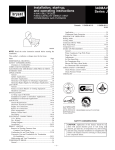
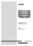
1
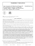
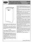
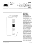
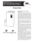
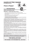
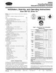
4-WAY MULTIPOISE
FIXED-CAPACITY NON-DIRECT-VENT
CONDENSING GAS FURNACE
345MAV
Sizes 040 thru 120
Combustion System—Enclosed burner assembly isolates
operating noise without the expense of sound deadening
devices. This furnace uses combustion air from an area adjacent to the furnace and brings it in through a short section of
inlet pipe that terminates just outside of the cabinet.
3-Pass Primary Heat Exchangers—This design accelerates
heat transfer and extracts heat that conventional heat exchangers waste up the flue. The primary heat exchanger is made of
aluminized steel for corrosion resistance.
Flow-Through Secondary Heat Exchangers—Each cell is
laminated with our patented Everlastic™ polypropylene for
greater resistance to corrosion. This breakthrough in heating
technology helps extend the life of the furnace for years of
dependable performance. The heat exchanger is positioned in
the furnace to extract additional heat from the combustion
products regardless of furnace orientation.
Warranty—Limited Lifetime Warranty on the heat exchangers
for the lifetime of original owner in single family residence; 20
years in other residential and commercial applications. 5 year
Limited Warranty on entire unit.
Monoport Inshot Burners—Produce precise air-to-gas mixture which gives a clean burn. The large monoport on the
inshot or injection-type burners seldom, if ever, needs cleaning.
Integrated Control Center—The printed-circuit board and all
internal wiring are factory installed. Convenient terminals permit quick-connection of a thermostat, and air conditioning
control circuits. Connections for a humidifier and air cleaner are
also provided.
4-WAY MULTIPOISE
CONDENSING GAS FURNACE
The model 345MAV Multipoise Condensing Furnace is specifically designed to meet the needs of the new construction
market. This high-efficiency furnace utilizes a unique 4-way
multipoise design and compact size to fit where other furnaces will not. The model 345MAV can be installed in any of 4
positions including horizontally in attics or crawlspaces, freeing space formerly used as a utility or furnace room. Sidewall
or through-the-roof venting options and the use of PVC pipe
eliminate the need for dedicated chimneys or chaseways to
facilitate furnace venting. Time-saving installation features
yield a very cost effective way to provide new home buyers
with a high-efficiency and high-quality home comfort system.
FEATURES
4-Way Multipoise Design—Allows a model 345MAV to be
installed in an upflow, downflow, or horizontal orientation.
The model 345MAV is available in 11 heat/airflow combinations and, when combined with the 4-way design, allows for 44
different application types. Factory configured for upflow application, this furnace can easily be made ready for downflow or
horizontal installation.
The control has a built-in status indicator and self-test feature.
The status indicator flashes to indicate a problem condition and
assists the servicer in diagnosis. The self-test feature allows for
a complete check of the major components in only seconds.
Combustion Air and Ventilation—The 345MAV advanced
design allows Schedule 40PVC, PVC-DWV, SDR-21 PVC,
SDR-26 PVC (not approved in Canada), ABS-DWV, or ABSF628 Schedule 40 pipe to bring air into the furnace for combustion. The extracted heat lowers the temperature of the combustion products to a point (typically below 115°F) that any of
the approved types of pipe can also be used for venting combustion products outside the structure. The vent pipe can
terminate through a sidewall or through the roof.
Insulated Casing—Foil-faced insulation in the heat exchanger
section cuts heat loss. The casing also has the required openings for left- or right-side connection of gas, electric, drain, and
vent connections.
Certifications—The 345MAV units are CSA (A.G.A. and
C.G.A.) design certified for use with natural and propane
gases, as well as GAMA efficiency rating certified. The furnace
is factory-shipped for use with natural gas. A CSA (A.G.A./
C.G.A.) certified gas conversion kit is required to convert furnace for use with propane gas. The model 345MAV meets
California Air Quality Management District emission
requirements.
Quality Registration—The 345MAV is engineered and manufactured under an ISO 9001 registered quality system.
Form No. PDS 345M.40.5
—2—
11⁄4"
1"
14 1⁄2"
TYP
26 15⁄16"
1
26 15⁄16" TYP
23 1⁄4" TYP
SIDE INLET
SIDE INLET
⁄2-IN. DIA THERMOSTAT
ENTRY
22 11⁄16"
2-IN. VENT CONN
DIA
GAS CONN
1⁄2-IN.
2-IN. COMBUSTIONAIR CONN
22 5⁄16"
24 1⁄2"
26 1⁄4"
/16"
11
E
INLET
OUTLET
D
/16"
11
18 1⁄4"
A
17-1/2
17-1/2
17-1/2
17-1/2
17-1/2
17-1/2
17-1/2
21
21
21
24-1/2
UNIT SIZE
024040
036040
024060
036060
048060
036080
048080
060080
048100
060100
060120
15-7/8
15-7/8
15-7/8
15-7/8
15-7/8
15-7/8
15-7/8
19-3/8
19-3/8
19-3/8
22-7/8
D
16
16
16
16
16
16
16
19-1/2
19-1/2
19-1/2
23
E
DIMENSIONS (In.)
TYP
9⁄16"
DIMPLE LOCATORS
FOR HORIZONTAL
HANGING
CONDENSATE
DRAIN LOCATION
(UPFLOW)
30 1⁄2"
CONDENSATE DRAIN
TRAP LOCATION
(DOWNFLOW &
HORIZONTAL RIGHT)
OR ALTERNATE
1⁄2-IN. DIA GAS CONN
13/16"
164
168
171
174
174
190
196
204
220
221
245
SHIP. WEIGHT (Lb)
NOTES: 1. Minimum return-air openings at furnace, based on metal duct. If flex duct is used,
see flex duct manufacturer’s recommendations for equivalent diameters.
2. Minimum return-air opening at furnace:
a. For 800 CFM–16-in. round or 141/2 x 12-in. rectangle.
b. For 1200 CFM–20-in. round or 141/2 x 191/2-in. rectangle.
c. For 1600 CFM–22-in. round or 141/2 x 231/4-in. rectangle.
d. For airflow requirements above 1800 CFM, see Air Delivery table in Product Data
literature for specific use of single side inlets. The use of both side inlets, a
combination of 1 side and the bottom, or the bottom only will ensure adequate
return air openings for airflow requirements above 1800 CFM at 0.5” W.C. ESP.
CONDENSATE
DRAIN LOCATION
(UPFLOW)
9 7⁄16"
TYP
33 1⁄4"
TYP
32 5⁄8"
TYP
13
30 ⁄16"
29 11⁄16"
TYP
27 5⁄8"
27 9⁄16"
TYP
24 1⁄2"
17 5⁄16"
CONDENSATE
DRAIN TRAP
LOCATION
(ALTERNATE
UPFLOW)
⁄8-IN. DIA
ACCESSORY
POWER ENTRY
7
DIA
POWER CONN
7⁄8-IN.
CONDENSATE DRAIN
TRAP LOCATION
(DOWNFLOW &
HORIZONTAL LEFT)
13/16"
A
AIRFLOW
24 3⁄16"
BOTTOM INLET
22 1⁄4" TYP
SIDE INLET
22 11⁄16"
2-IN. VENT CONN
1
⁄2-IN. DIA
THERMOSTAT ENTRY
⁄8-IN. DIA
POWER CONN
7
⁄2-IN. DIA
GAS CONN
1
2-IN. COMBUSTIONAIR CONN
OUTLET
19"
22 5⁄16"
26 1⁄4"
28 1⁄2"
26 15⁄16"
A02147
11⁄16"
7⁄16"
1"
39 7⁄8"
⁄16"
5
5⁄8"
13⁄16"
CONDENSATE TRAP
FURNACE
DOOR
BLOWER SHELF
CONDENSATE
TRAP
CONDENSATE
TRAP (INSIDE)
FURNACE
DOOR
FURNACE
SIDE
4 78
FURNACE
SIDE
4
534
534
4
FIELD
DRAIN
CONN
ALTERNATE DRAIN
TUBE LOCATION
26 1 4
26 1 4
11 2
SIDE VIEW
CONDENSATE TRAP
DRAIN TUBE LOCATION
FIELD
DRAIN
CONN
FRONT VIEW
END VIEW
SLOT FOR SCREW
HORIZONTAL
APPLICATION
(OPTIONAL)
FRONT VIEW
HORIZONTAL
APPLICATIONS
DOWNFLOW AND ALTERNATE
EXTERNAL UPFLOW APPLICATIONS
UPFLOW APPLICATIONS
34
1⁄4 OD
COLLECTOR BOX TO
TRAP RELIEF PORT
11 2
1⁄2 OD
INDUCER HOUSING
DRAIN CONNECTION
34
5⁄8 OD
COLLECTOR BOX
DRAIN CONNECTION
71 8
SCREW HOLE FOR
UPFLOW OR DOWNFLOW APPLICATIONS
(OPTIONAL)
13 4
WIRE TIE
GUIDES
(WHEN USED)
FRONT VIEW
78
21 4
1⁄2-IN.
PVC OR CPVC
SIDE VIEW
ama
A93026
CERTIFIED
MEETS DOE RESIDENTIAL
CONSERVATION SERVICES
PROGRAM STANDARDS.
Before purchasing this appliance, read
important energy cost and efficiency
information available from your retailer.
As an ENERGY STAR Partner,
Bryant Heating and Cooling
Systems has determined that
this product meets the
ENERGY STAR guidelines for
energy efficiency.
REGISTERED QUALITY SYSTEM
These products are engineered and
manufactured under an ISO 9001
registered quality system.
—3—
SPECIFICATIONS
UNIT SIZE
024040
036040
024060
036060
048060
RATINGS AND PERFORMANCE
Input Btuh*
40,000
40,000
60,000
60,000
60,000
Output Capacity†
Nonweatherized ICS
37,000
37,000
55,000
55,000
55,000
AFUE%†
Nonweatherized ICS
90.0
90.0
90.0
90.0
90.0
30—60
15—45
45—75
30—60
20—50
Certified Temperature Rise Range (°F)
Certified External Static Pressure
Airflow CFM‡
Heating
0.10
0.10
0.12
0.12
0.12
Cooling
0.50
0.50
0.50
0.50
0.50
Heating
850
1125
885
1065
1320
Cooling
895
1215
900
1200
1545
ELECTRICAL
Unit Volts—Hertz—Phase
115—60—1
Operating Voltage Range Min—Max**
104—127
Maximum Unit Amps
6.1
7.3
6.1
7.1
9.5
Unit Ampacity††
8.4
10.0
8.4
9.8
12.8
Minimum Wire Size
14
14
14
14
14
Maximum Wire Length (Ft)‡‡
44
37
44
38
29
Maximum Fuse Size or Ckt Bkr Amps***
15
15
15
15
15
Transformer (24v)
40va
External Control
Heating
12va
Power Available
Cooling
21va
Air Conditioning Blower Relay
Standard
CONTROLS
Limit Control
SPST
Heating Blower Control (Off Delay)
Selectable 90, 120, 150, or 180 Sec
Burners (Monoport)
2
2
3
Gas Connection Size
3
3
1/2-in. NPT
GAS CONTROLS
Gas Valve
Manufacturer
White-Rodgers
Min Inlet Pressure (In. wc)
4.5 (Natural Gas)
Max Inlet Pressure (In. wc)
13.6 (Natural Gas)
Ignition Device
Hot Surface
BLOWER DATA
Direct-Drive Motor HP (PSC)
1/5
1/3
1/5
1/3
1/2
Motor Full Load Amps
4.9
5.8
5.8
7.9
1075—3
1075—4
4.9
1075—3
10 x 6
10 x 7
10 x 6
10 x 7
RPM (Nominal)—Speeds
Blower Wheel Diameter x Width (In.)
Filter Size (In.)—Permanent Washable
1075—4
11 x 8
(1) 16 x 25 x 1
FACTORY-AUTHORIZED AND LISTED, DEALER-INSTALLED OPTIONS
Electronic Air Cleaner
Model EACA
Mechanical Air Cleaner
EZXCAB, or FILCAB
Humidifier
Model HUM
Heat Recovery Ventilator
HRV
Twinning Kit†††
N/A
Energy Recovery Ventilator
KGATW0601HSI
ERV
Side Filter Rack (Without Filter)†††
KGAFR0206ALL
Condensate Freeze Protection Kit
KGAHT0101CFP
Condensate Neutralizer Kit (Obtained thru RCD)
P908-0001
Downflow Base (For Combustible Floors With or
Without A/C Coil)
KGASB0201ALL
Gas Conversion Kit—Natural-to-Propane
KGANP2901ALL
Gas Conversion Kit—Propane-to-Natural
KGAPN2301ALL
Vent/Exhaust Pipe External Trap Kit
KGAET0106ETK
UV Lights
Model UVL
See notes on page 5.
—4—
SPECIFICATIONS Continued
UNIT SIZE
036080
048080
060080
048100
060100
060120
RATINGS AND PERFORMANCE
Input Btuh*
80,000
80,000
80,000
100,000
100,000
120,000
Output Capacity†
Nonweatherized ICS
74,000
74,000
74,000
92,000
92,000
111,000
AFUE%†
Nonweatherized ICS
90.0
90.0
90.0
90.0
90.0
90.0
40—70
30—60
20—50
45—75
30—60
40—70
Certified Temperature Rise Range (°F)
Certified External Static Pressure
Airflow CFM‡
Heating
0.15
0.15
0.15
0.20
0.20
0.20
Cooling
0.50
0.50
0.50
0.50
0.50
0.50
Heating
1190
1285
1785
1315
1690
1720
Cooling
1245
1525
1925
1570
1930
2000
ELECTRICAL
Unit Volts—Hertz—Phase
115—60—1
Operating Voltage Range Min—Max**
104—127
Maximum Unit Amps
7.6
10.0
14.1
10.2
14.8
14.6
Unit Ampacity††
10.4
13.4
18.4
13.5
19.3
19.1
Minimum Wire Size
14
14
12
14
12
12
Maximum Wire Length (Ft)‡‡
36
28
31
27
30
30
Maximum Fuse Size or Ckt Bkr Amps
(Time-delay type recommended)
15
20
15
20
20
Transformer (24v)
40va
External Control
Heating
12va
Power Available
Cooling
21va
Air Conditioning Blower Relay
Standard
CONTROLS
Limit Control
SPST
Heating Blower Control (Off Delay)
Selectable 90, 120, 150, or 180 Sec
Burners (Monoport)
4
4
4
5
Gas Connection Size
5
6
1/2-in. NPT
GAS CONTROLS
Gas Valve
Manufacturer
White-Rodgers
Min Inlet Pressure (In. wc)
4.5 (Natural Gas)
Max Inlet Pressure (In. wc)
13.6 (Natural Gas)
Ignition Device
Hot Surface
BLOWER DATA
Direct-Drive Motor HP (PSC)
1/3
1/2
3/4
1/2
3/4
3/4
Motor Full Load Amps
5.8
7.9
11.1
7.9
11.1
11.1
10 x 7
11 x 8
11 x 10
11 x 8
11 x 10
RPM (Nominal)—Speeds
Blower Wheel Diameter x Width (In.)
1075—4
Filter Size (In.)—Permanent Washable
(1) 20 x 25 x 1
11 x 10
(1) 24 x 25 x 1
FACTORY-AUTHORIZED AND LISTED, DEALER-INSTALLED OPTIONS
Electronic Air Cleaner
Model EACA
Mechanical Air Cleaner
EZXCAB, or FILCAB
Humidifier
Model HUM
Heat Recovery Ventilator
Twinning Kit†††
HRV
N/A
Energy Recovery Ventilator
KGATW0601HSI
ERV
Side Filter Rack (Without Filter)†††
KGAFR0206ALL
Condensate Freeze Protection Kit
KGAHT0101CFP
Condensate Neutralizer Kit (Obtained thru RCD)
P908-0001
Downflow Base***
KGASB0201ALL
Gas Conversion Kit—Natural-to-Propane
KGANP2901ALL
Gas Conversion Kit—Propane-to-Natural
KGAPN2301ALL
Vent/Exhaust Pipe External Trap Kit
KGAET0106ETK
UV Lights
Model UVL
* Gas input ratings are certified for elevations to 2000 ft. For elevations above 2000 ft, reduce ratings 2% for each 1000 ft above sea level. In Canada,
derate the unit 5% for elevations 2000 to 4500 ft above sea level.
† Capacity and AFUE in accordance with U.S. Government DOE test procedures.
‡ Airflow shown is for bottom only return-air supply. For air delivery above 1800 CFM at 0.5'' W.C. ESP, see Air Delivery Table for other options. A filter is
required for each return-air supply.
** Permissible voltage limits for proper furnace operation.
†† Unit ampacity = 125% of largest component’s full load amps plus 100% of all other potential operating components’ (EAC, humidifier, etc.) full load amps.
‡‡ Length shown is measured 1 way along wire path between unit and service panel for maximum 2% voltage drop.
*** Required for installation on combustible floors when no coil box is used, or when any coil box other than a Bryant CD5, CK5, or KCAKC cased coil is used.
††† See kit Installation Instructions for details.
N/A—Not applicable
ICS—Isolated Combustion System
PSC—Permanent Split Capacitor
—5—
VENT PIPING
MAXIMUM ALLOWABLE VENT PIPE LENGTH (FT)
ALTITUDE
ABOVE SEA
LEVEL (FT)
UNIT SIZE
024040
036040
024060
036060
048060
0 to 2000
036080
048080
060080
048100
060100
060120
024040
036040
2001 to 3000
024060
036060
048060
036080
048080
060080
048100
060100
060120
024040
036040
3001 to 4000
024060
036060
048060
036080
048080
060080
048100
060100
060120
024040
036040
4001 to 5000†
024060
036060
048060
036080
048080
060080
048100
060100
060120
024040
036040
5001 to 6000†
024060
036060
048060
036080
048080
060080
048100
060100
060120
VENT PIPE
DIA
(IN.)
1
1-1/2
2
1-1/2
1
5
70
70
20
2
NA
70
70
15
2
1-1/2
2
2-1/2
2
2-1/2
3
2-1/2
3*
1-1/2
2
1-1/2
70
10
55
70
5
40
70
10
70
67
70
17
70
NA
50
70
NA
30
70
NA
70
62
70
12
70
NA
35
70
NA
20
70
NA
70
57
70
7
2
2
70
49
67
44
2-1/2
2-1/2
3
3*
1-1/2
2
1-1/2
70
35
70
63
64
70
16
2
2
NUMBER OF 90°ELBOWS
3
4
NA
NA
65
60
70
70
10
5
5
NA
60
70
NA
6
NA
55
70
NA
70
NA
30
70
NA
20
70
NA
70
52
70
NA
70
NA
30
70
NA
10
70
NA
70
52
70
NA
70
NA
20
70
NA
NA
70
NA
70
47
70
NA
66
30
61
25
61
25
61
15
70
26
70
62
59
70
11
70
16
70
62
54
70
6
70
16
70
61
49
70
NA
70
6
66
61
48
70
NA
70
NA
61
61
43
70
NA
68
46
63
41
62
28
57
23
57
22
56
13
2-/12
2-1/2
3
3*
1-1/2
2
1-1/2
70
33
70
59
60
70
15
70
24
70
59
55
70
10
70
15
70
58
50
70
5
70
14
66
57
45
70
NA
70
5
61
57
44
70
NA
70
NA
56
56
39
70
NA
2
2
64
44
59
39
58
26
53
21
52
20
52
11
2-1/2
2-1/2
3
3*
1-1/2
2
1-1/2
70
31
70
56
57
70
14
70
22
70
55
52
70
9
70
13
67
54
47
70
NA
70
12
62
53
42
70
NA
70
NA
57
52
40
70
NA
70
NA
52
52
35
70
NA
2
2
60
41
55
36
54
23
49
18
48
17
47
8
2-1/2
2-1/2
3
3*
70
29
70
53
70
21
67
52
70
12
62
50
70
11
57
49
70
NA
52
48
70
NA
47
47
See notes on page 7.
—6—
MAXIMUM ALLOWABLE VENT PIPE LENGTH (FT) Continued
ALTITUDE
ABOVE SEA
LEVEL (FT)
UNIT SIZE
024040
036040
6001 to 7000†
024060
036060
048060
036080
048080
060080
048100
060100
060120
024040
036040
7001 to 8000†
024060
036060
048060
036080
048080
060080
048100
060100
060120
024040
036040
8001 to 9000†
024060
036060
048060
036080
048080
060080
048100
060100
060120
024040
036040
9001 to
10,000†
024060
036060
048060
036080
048080
060080
048100
060100
060120
VENT PIPE
DIA
(IN.)
1-1/2
2
1-1/2
1
53
70
13
2
48
70
8
2
2
57
38
52
33
50
21
2-1/2
2-1/2
3
3*
1-1/2
2
1-1/2
70
27
68
49
49
66
12
70
19
63
48
44
65
7
2
2
53
36
2-1/2
2-1/2
3
3*
1-1/2
2
1-1/2
NUMBER OF 90° ELBOWS
3
4
43
38
68
67
NA
NA
5
37
66
NA
6
32
64
NA
45
16
44
15
43
6
68
10
58
47
39
63
NA
67
9
53
45
34
62
NA
66
NA
48
44
33
60
NA
64
NA
43
43
28
59
NA
48
31
46
19
41
14
40
12
38
NA
66
25
63
46
46
62
11
65
17
58
44
41
60
6
63
8
53
43
36
58
NA
62
7
48
41
31
56
NA
60
NA
43
40
29
55
NA
59
NA
38
38
24
53
NA
2
2
49
33
44
28
42
17
37
12
35
10
34
NA
2-1/2
2-1/2
3
3*
1-1/2
2
62
23
59
43
42
57
60
15
54
41
37
55
58
7
49
39
32
53
56
5
44
37
27
51
55
NA
39
35
25
49
53
NA
34
34
20
47
2
45
40
38
33
31
29
2
30
25
14
9
7
NA
2-1/2
2-1/2
3
3*
57
21
54
39
55
13
49
37
53
5
44
35
51
NA
39
33
49
NA
34
31
47
NA
29
29
* Wide radius elbow.
† Vent sizing for Canadian installations above 4500 ft (1370m) above sea level are subject to acceptance by the local authorities having jurisdiction.
NA — Not Allowed; pressure switch will not make.
NOTES:
1. Do not use pipe size greater than those specified in table or incomplete combustion, flame disturbance, or flame sense lockout may occur.
2. Assume two 45° elbows equal one 90° elbow. Long radius elbows are desirable and may be required in some cases.
3. Elbows and pipe sections within the furnace casing and at the vent termination should not be included in vent length or elbow count.
4. The minimum pipe length is 5 ft for all applications.
—7—
MAXIMUM ALLOWABLE EXPOSED VENT PIPE LENGTH (FT) WITH INSULATION
IN WINTER DESIGN TEMPERATURE AMBIENT*
INSULATION THICKNESS (IN.)†
UNIT SIZE
024040
036040
024060
036060
048060
036080
048080
060080
048100
060100
060120
WINTER DESIGN MAXIMUM PIPE
TEMP °F
DIA (IN.)
20
1-1/2
0
1-1/2
–20
1-1/2
20
2
0
2
–20
2
20
2-1/2
0
2-1/2
–20
2-1/2
20
3
0
3
–20
3
20
3
0
3
–20
3
0
3/8
1/2
3/4
1
31
16
9
45
25
16
55
31
20
61
33
20
70
40
26
56
34
23
70
51
36
70
61
43
70
65
45
70
70
55
63
39
27
70
58
42
70
69
49
70
70
52
70
70
64
70
47
34
70
70
51
70
70
61
70
70
65
70
70
70
70
54
39
70
70
60
70
70
70
70
70
70
70
70
70
* Pipe length (ft) specified for maximum vent pipe lengths located in unconditioned spaces. Vent pipes located in unconditioned space cannot exceed the total
allowable pipe length as specified in Maximum Allowable Pipe Length table.
† Insulation thickness based on R value of 3.5 per in.
—8—
CLEARANCE TO COMBUSTIBLES
INSTALLATION
This forced air furnace is equipped for use with natural gas at altitudes 0 - 10,000 ft (0 - 3,050m), except 140 size Furnaces are only approved for altitudes 0 - 7,000 ft. (0 - 2,135m).
An accessory kit, supplied by the manufacturer, shall be used to convert to propane gas use or may be required for some natural gas applications.
This furnace is for indoor installation in a building constructed on site. This furnace may be installed in a manufactured (mobile) home when stated on rating plate and using factory
authorized kit.
This furnace may be installed on combustible flooring in alcove or closet at minimum clearance from combustible material.
This appliance requires a special venting system. Refer to the installation instructions for parts list and method of installation. This furnace is for use with schedule-40 PVC, PVC-DWV,
CPVC, or ABS-DWV pipe, and must not be vented in common with other gas-fired appliances. Construction through which vent/air intake pipes may be installed is maximum 24 inches
(600 mm), minimum 3/4 inches (19 mm) thickness (including roofing materials).
Cette fournaise à air pulsé est équipée pour utilisation avec gaz naturel et altitudes comprises entre 0 - 3,050m
(0-10,000 pi), excepté queles fournaises de 140 taille sont pour altitudes comprises entre 0 - 2,135m (0 - 7,000 pi).
Utiliser une trousse de conversion, fournie par le fabricant, pour passer au gaz propane ou pour certaines installations au gaz naturel.
Cette fournaise à air pulsé est pour installation à l´intérieur dans un bâtiment construit sur place. Cette fournaise à air pulsé peut être installée dans une maison préfabriquée
(maison mobile) si prescrit par la plaque signalétique et si l´on utilise une trousse specifiée par le fabricant.
Cette fournaise peut être installée sur un plancher combustible dans un enfoncement ou un placard en observant les dégagements minimums avec les matériaux combustibles.
Cet appareil nécessite un système d´évacuation spécial. La méthode d´installation et la liste des pièces nécessaires figurent dans les instructions d´installation.Cette fournaise doit
s´utiliser avec la tuyauterie des nomenclatures 40 PVC, PVC-DWV, CPVC, ou ABS-DWV et elle ne peut pas être ventilée conjointment avec d´autres appareils à gaz. Épaisseur de la
construction au travers de laquelle il est possible de faire passer les tuyaux d´aération (admission/évacuation): 24 po (600 mm) maximum, 3/4 po (19 mm) minimum (y compris la toiture).
For upflow and downflow applications, furnace must be installed level, or pitched within 1/2"
of level. For a horizontal application, the furnace must be pitched minimum 1/4" to
maximum of 1/2" forward for proper drainage. See Installation Manual for IMPORTANT unit
support details on horizontal applications.
Pour des applications de flux ascendant et descendant, la fournaise doit être installée de
niveau ou inclinée à pas plus de 1/2" du niveau. Pour une application horizontale, la
fournaise doit être inclinée entre minimum 1/4" et maximum 1/2" du niveau pour le drainage
approprié. En cas d'installation en position horizontale, consulter les renseignements
IMPORTANTS sur le support dans le manuel d'installation.
LEVEL (0")
TO
1/2" MAX
UPFLOW OR
DOWNFLOW
MIN 1/4"
TO
1/2" MAX
FRONT
MINIMUM INCHES CLEARANCE TO COMBUSTIBLE CONSTRUCTION
R
Cette fournaise est approuvée pour l´installation HORIZONTALE
et la circulation d´air VERS LE HAUT et VERS LE BAS.
Minimum front clearance for service 30 inches (762mm).
140 size furnaces require 1 inch back clearance to combustible materials.
DOWNFLOW POSITIONS:
†
Clearance arrows
do not change with
furnace orientation.
For installation on combustible floors only when installed on special base No. KGASB0201ALL, Coil
Assembly, Part No. CD5 or CK5, or Coil Casing, Part No. KCAKC.
HORIZONTAL POSITIONS:
§
Line contact is permissible only between lines formed by intersections of top and two sides of furnace
jacket, and building joists, studs, or framing.
Clearance shown is for air inlet and air outlet ends.
120 and 140 size furnaces require 1 inch bottom clearance to combustible materials.
††
0"B
A
Ø
DÉGAGEMENT MINIMUM EN POUCES AVEC ÉLÉMENTS DE CONSTRUCTION COMBUSTIBLES
R
A
C
RI K
ER
E
POUR TOUS LES POSITIONS :
*
Dégagement avant minimum de 762mm (30 po) pour l´entretien.
1"
TOP/PLENUM
DESSUS/CHAMBRE D´AI
*
HORIZONTAL
This furnace is approved for UPFLOW, DOWNFLOW and
HORIZONTAL installations.
ALL POSITIONS:
††
FRONT
Les fléches de dégagement
ne change pas avec
l´orientation de la
générateur d´air chaud.
E
AC SE
RN A I
F U URN
T
ON
FO
F R AN T
V
A
†† Pour les fournaises de 140 taille, 1 po (25mm) dégagement des matériaux combustibles est requis
au-arriere.
POUR LA POSITION COURANT DESCENDANT:
n° KGASB0201ALL, l´ensemble serpentin, pièce n° CD5 ou CK5, ou le carter de serpentin, pièce
n° KCAKC.
§
0"
POUR LA POSITION HORIZONTALE:
§
Ø
Le contact n´est permis qúentre les lignes formées par les intersections du dessus et des deuxcôtés de la
chemise de la fournaise, et des solives, des montants ou de la charpente du bátiment.
La distance indiquée concerne l´extrémité du tuyau d´arrivée d´air et l´extrémité du tuyau de sortie d´air.
Pour les fournaises de 120 et 140 taille, 1 po (25mm) dégagement des matériaux combustibles est requis
au-dessous.
Clearance in inches
Dégagement (po).
324999-201 REV. D (LIT TOP)
F
R
A V ON
T
A
NT
BOTTOM
DESSOUS
† Pour l´installation sur le plancher combustible seulement quand on utilise la base spéciale, pièce
DE
SI E S
T
O
C
0"
†Ø
DE
SI E S
T
O
C
LÈ
0" §
S
E
NT R VI
RE C
TI E
EN
MIN
3"
Vent clearance to
combustibles 0".
0 (po) Dégagement
d´évent avec combustibles.
A02148
ACCESSORY SIDE FILTER RACK*
1
1⁄
4″
(TYP)
3⁄ ″
8
TABS
1⁄
2″
2 3⁄8″
1 1⁄4″
17 1⁄8″
25 1⁄8″
23 1⁄8″
OPENING
3⁄
4″
16 1⁄8″
14 1⁄2″
OPENING
A80199
*Accepts one 16 x 25 x 1 in. filter.
—9—
*
30
AIR DELIVERY—CFM (With Filter)*
UNIT SIZE
RETURN-AIR
SUPPLY
024040
1 side
or
bottom
036040
1 side
or
bottom
024060
1 side
or
bottom
036060
1 side
or
bottom
048060
1 side
or
bottom
036080
1 side
or
bottom
048080
1 side
or
bottom
060080
1 side
or
bottom
both sides or
1 side and
bottom
048100
060100
1 side
or
bottom
1 side
or
bottom
both sides or
1 side and
bottom
bottom
only
060120
both sides or
1 side and
bottom
1 side only
SPEED
EXTERNAL STATIC PRESSURE (In. wc)
0.3
0.5
0.4
0.6
0.2
1040
825
700
1415
1280
1110
925
1065
865
710
1375
1260
1055
895
1695
1465
1295
1170
1470
1350
1175
1020
1685
1455
1260
1105
2175
2025
1760
1555
2280
1925
0.7
0.8
High
Med-Low
Low
High
Med-High
Med-Low
Low
High
Med-Low
Low
High
Med-High
Med-Low
Low
High
Med-High
Med-Low
Low
High
Med-High
Med-Low
Low
High
Med-High
Med-Low
Low
High
Med-High
Med-Low
Low
High
Med-High
0.1
1075
850
740
1470
1315
1125
930
1100
890
745
1430
1270
1070
915
1700
1500
1325
1205
1535
1395
1200
1040
1750
1495
1310
1135
2200
2100
1815
1560
2360
1965
995
780
650
1400
1235
1085
910
1005
810
670
1325
1215
1045
885
1640
1435
1265
1145
1405
1300
1125
990
1635
1405
1225
1075
2085
1945
1720
1515
2210
1870
945
740
620
1285
1180
1045
850
945
765
625
1275
1160
1015
865
1580
1385
1230
1110
1330
1125
1065
960
1575
1355
1170
1040
2025
1865
1670
1460
2130
1830
895
685
565
1215
1115
990
830
900
705
565
1200
1105
975
840
1545
1355
1190
1080
1245
1155
1030
910
1525
1305
1125
995
1925
1785
1620
1435
2035
1760
840
635
515
1120
1035
915
770
805
620
505
1135
1035
920
800
1450
1300
1150
1035
1160
1080
970
860
1445
1250
1095
995
1820
1700
1550
1390
1960
1710
760
560
455
995
930
830
705
730
540
425
1040
950
850
720
1380
1250
1105
990
1065
985
890
785
1380
1185
1040
910
1735
1620
1480
1340
1875
1670
670
480
385
890
825
740
635
610
475
360
935
850
750
650
1310
1185
1050
950
935
880
780
680
1310
1120
980
860
1635
1540
1405
1270
1790
1575
High
Med-High
Med-Low
Low
High
Med-High
Med-Low
Low
High
Med-High
1740
1500
1340
1195
2250
2020
1725
1490
2360
1960
1705
1470
1315
1175
2175
1950
1690
1480
2315
1940
1660
1445
1300
1165
2090
1900
1660
1460
2265
1930
1615
1410
1270
1130
2020
1840
1630
1440
2200
1900
1570
1375
1235
1100
1930
1790
1575
1380
2130
1850
1500
1330
1200
1070
1855
1710
1520
1340
2055
1800
1425
1280
1140
1030
1760
1640
1460
1295
1965
1740
1355
1210
1095
975
1670
1545
1370
1230
1890
1660
High
Med-High
Med-Low
Low
High
Med-High
2350
2100
1770
1545
2435
2040
2250
2015
1720
1520
2360
2000
2160
1955
1675
1465
2285
1950
2070
1875
1620
1415
2220
1905
2000
1810
1575
1365
2130
1835
1885
1710
1515
1325
2050
1790
1790
1650
1450
1265
1965
1725
1635
1540
1365
1185
1875
1650
High
Med-High
2255
1985
2190
1930
2115
1890
2045
1840
1965
1780
1890
1720
1800
1645
1710
1560
*A filter is required for each return-air suppy.
• For horizontal and downflow applications, use “1 side or bottom” or “bottom only” as airflow reference.
—10—
—11—
SPECIFICATIONS SUBJECT TO CHANGE WITHOUT NOTICE
UNIT MUST BE INSTALLED IN ACCORDANCE
WITH INSTALLATION INSTRUCTIONS
Cancels: 345M.40.4
© 2003 Bryant Heating & Cooling Systems, 7310 W. Morris St., Indianapolis, IN 46231
—12—
PRINTED IN U.S.A.
Catalog No. 5234-505
12-03