1
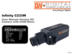
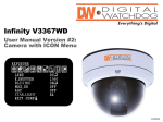
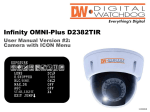
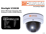
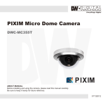
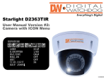
DWC-MC352 / MC352-29 / MC352DIR /
Micro Dome Camera
User Manual
5436 W Crenshaw St. Tampa, FL 33634
Tel: 866-446-3595 / 813-888-9555
Fax: 813-888-9262
www.Digital-Watchdog.com
[email protected]
Technical Support Hours: Monday-Friday
8:30am to 8:00pm Eastern Time
ABOUT MANUAL
Before installing and using the camera, please read this manual carefully.
Be sure to keep it handy for future reference.
12232010
PRECAUTIONS
Do not open or modify.
Do not open the case except during maintenance and installation,
for it may be dangerous and can cause damages.
■ Do not put objects into the unit.
■ Keep
metal objects and flammable substances from entering the camera. It can cause fire, short- circuits,
or other damages.
■ Be careful when handling the unit.
■ To prevent damages, do not drop the camera or subject it to shock or vibration.
■ Do not install near electric or magnetic fields.
■ Protect from humidity and dust.
■ Protect from high temperature.
■ Be careful when installing near the ceiling of a kitchen or a boiler room, as the temperature may rise to
high levels.
■ Cleaning
■ To remove dirt from the case, moisten a soft cloth with a soft detergent solution and wipe.
■ Mounting Surface
■ The material of the mounting surface must be strong enough to support the camera.
■
DIMENSIONS*
■
FCC COMPLIANCE
This equipment has been tested and found to comply with the limits for a Class B digital device, pursuant
to Part 15 of the FCC rules. These limits are designed to Provide reasonable protection against harmful
interference .when the equipment is operated in a residential environment. This equipment generates, uses,
and radiates radio frequency energy; and if it is not installed and used in accordance with the instruction
manual, it may cause harmful interference to radio communications.
R25.0
20.5
7.5
49.0
8.4
9.5
11.5
ø56.0
ø80.0
VIDEO(yellow)
BNC JACK
ø66.5
WARNING : Changes or modifications are not expressly approved by the manufacturer.
TROUBSHOOTING
4 ø4.5
RED
BLACK
DC12V
0.2 INCHES(5.0mm)
TWIST SOLDERING
Before sending your camera for repair, check the following or contact our technical specialist.
No VIDEO
Check the coaxial cable and make sure it is connected securely.
Check the lens’ iris adjustment at the menu setup of the camera.
Check the power supply and make sure the camera has the proper voltage and current.
Out-of-Focus VIDEO
Check the clear dome cover and the lens for dirt or fingerprints. Use a soft cloth and gently clean.
Check the lens manual focal and zoom adjustment. Field test monitor is recommended.
2
3
CAMERA SETTING AND INSTALLATION*
CONNECTIONS AND LENS ADJUSTMENTS*
■CONNECTIONS
■LENS ADJUSTMENTS
A
A
B
B
C
DC 12V
VIDEO OUT
41°
C
62.0°
D
D
E
CAUTION
Check for polarity when using a DC 12V power supply.
4
With LED Type
Without LED Type
Adjust the pan(360˚)
and tilt(41˚) position.
※ MC352DIR
Adjust the pan(360˚)
and tilt(62˚) position.
※ MC352,MC352-29
E
G
Camera Position Adjustment :
(1)Loosen the SCREW(B) on the UPPER CASE(C), using the L-WRENCH(A).
(2)Separate BOTTOM CASE(E) from
UPPER CASE(C) by turning UPPER
CASE(C) to the right.
(3)Separate CLEAR DOME(D) from BOTTOM CASE(E).
(4)Adjust the camera gimbal in BOTTOM CASE(E).
(5)Assemble CLEAR DOME(D) and
UPPER CASE(C) with BOTTOM CASE(E)
(6)Tighten the SCREW(B) on the UPPER
CASE(C), using the L-WRENCH(A).
F
1 R
emove 1 STOP SCREW(B) on UPPER CASE(C), using the L-WRENCH(A).
2 Separate UPPER CASE(C) from BOTTOM CASE(E).
3 Make the 4 mounting screw hole on the ceiling
/wall. The holes of BOTTOM CASE(E) can help
to make the correct hole location.
4 Put POWER CABLE(F) and VIDEO CABLE(G) into
the ceiling/wall.
5 Fix the BOTTOM CASE(E) onto the ceiling/wall
by using the SCREWS(D).
6 Camera Adjustment and Setting.
(Referance - “CAMERA SETTING” )
7 Connect UPPER CASE(C) and BOTTOM CASE(E).
8 Tighten the STOP SCREWS(B) onto the UPPER CASE(C), using the L-WRENCH(A).
5
WARRANTY INFORMATION*
Digital Watchdog (referred to as “the Warrantor”) warrants the Camera Series against defects in
materials or workmanship as follows.
LABOR : For the initial five (5) years and one (1) year on LED from the date of original purchase, if the camera is
determined to be defective, the Warrantor will repair or replace the unit, with new or refurbished product at its option,
at no charge.
PARTS : In addition, the Warrantor will supply replacement parts for the initial five (5) years and one (1) year on LED.
To obtain warranty or out of warranty service, please contact a Technical Support Representative at 1-866-4463595 Monday through Friday from 8:30AM to 8:00PM Eastern.
A purchase receipt or other proof of the original purchase date is required before warranty service is rendered. This
warranty only covers failures due to defects in materials and workmanship which arise during normal use. This
warranty does not cover damagethat occurs in shipment or failures caused by products not supplied by the Warrantor
or failures which result from accident, misuse, abuse, neglect, mishandling, misapplication, alteration, modification,
faulty installation, set-up adjustments, improper antenna, inadequate signal pickup, maladjustment of consumer
controls, improper operation, power line surge, improper voltage supply, lightning damage, rental use of the product
or service by anyone other than an authorized repair facility or damage that is attributable to acts of God.
LIMITS AND EXCLUSIONS*
There are no express warranties except as listed above. The Warrantor will not be liable for incidental or
consequential damages (including without limitation and damage to recording media) resulting from the use
of these products, or arising out of any breach of the warranty. All express and implied warranties, including the
warranties of merchantability and fitness for particular purpose, are limited to the applicable warranty period set
forth above.
Some states do not allow the exclusion or limitation of incidental or consequential damages, or
limitations on how long an implied warranty lasts, so the above exclusions or limitations may not
apply to you. This warranty gives you specific legal rights, and you may also have other rights that
vary from state to state.
If the problem is not handled to your satisfaction, then write to the Address listed on the back page.
Service calls which do not involve defective materials or workmanship as determined by the
Warrantor in its sole discretion are not covered. Costs of such service calls are the responsibility of the
purchase
6
SPECIFICATIONS*
Model
Camera TYPE
Color
MC352 / MC352-29 / MC352DIR
Vandal-Proof Micro Dome Camera
Mount
Device
Pixels-Total
Pixels-Effective
Scanning
System
Horizontal Frequency Internal Mode
Horizontal Frequency Line-Lock Mode
Vertical Frequency Internal Mode
Vertical Frequency Line-Lock Mode
F1.2: 30IRE (MC352, MC352-29), IR LED
Min. Scene Illumination
(MC352DIR)
IR DISTANCE
IR (MC352DIR only)
DIR Switch
Lens
Fixed Length
Resolution
Horizontal
Video Output
VBS 1.0Vp-p
S/N Ratio
S/N Ratio
Environmental Conditions Operating Temperature
Humidity
Power
Power Requirement
Power Consumption
Physical Specification
Dimensions( x H)
Nema Type
Weight
Certifications
CE, FCC, RoHS
Image
M9
1/3” Super HAD ll CCD
811(H) x 508(V)
768(H) x 494(V)
NTSC
15,734Hz
N/A
59.94Hz
N/A
0.2Lux(MC352, MC352-29), 0Lux(MC352DIR)
23ft Range
N/A
3.6mm (MC352, MC352DIR), 2.9mm(MC352-29)
540 TV
1.0Vp-p
48dB
-10oC ~ 50oC (14oF ~ 122oF)
Less than 90%
12VDC
12VDC: 77mA(MC352, MC352-29), 160mA(MC352DIR)
80 X 49 mm (3.15 X 1.93 in)
IP66
160g (0.353 lbs)
Certified
7