1
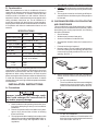
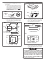
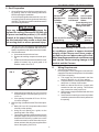
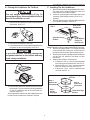
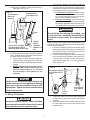
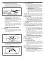
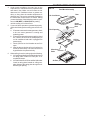
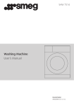
Type 3253.332 Installation and Operating Instructions
RECORD THIS UNIT INFORMATION FOR FUTURE
REFERENCE:
Model Number
Serial Number
Date Purchased
MODEL B3200
Roof-Top Air Conditioner
used with
Mechanical Air Distribution Box
SERVICE OFFICE
Dometic Corporation
For Information
Contact:
www.dometic.com
This manual must be read and understood before installation, adjustment, service, or maintenance
is performed. This unit must be installed by a qualified service technician. Modification of this product
can be extremely hazardous and
could result in personal injury or
property damage.
INSTALLATION & OPERATING
INSTRUCTIONS
REVISION:
Form No. 3310070.010 4/06
(Replaces 3310070.000)
©2006 Dometic Corporation
LaGrange, IN 46761
Important: These Instructions
must stay with unit.
Owner read carefully.
1
TYPE
3253.332
Air Conditioner
Type 3253.332 Installation and Operating Instructions
GENERAL INSTRUCTIONS
SAFETY INSTRUCTIONS
A. Product features or specifications as described or illustrated are subject to change without notice.
The following are the basic requirements:
1. Installation opening. Cut through the roof and ceiling.
2. Additional Wiring.
220-240 VAC, 50 Hz. 10 Amp.
3. Power with the air conditioner on must be above 209
VAC and the frequency must be at 50 HZ. at all
times.
This manual has safety information and instructions to help users eliminate or reduce the risk of
accidents and injuries.
RECOGNIZE SAFETY INFORMATION
!
B. This Air Conditioner Is Designed For:
This is the safety-alert symbol. When you see this
symbol in this manual, be alert to the potential for
personal injury.
C.
Follow recommended precautions and safe operating instructions.
UNDERSTAND SIGNAL WORDS
A signal word , WARNING OR CAUTION is used
with the safety-alert symbol. They give the level of
risk for potential injury.
! WARNING indicates a potentially hazardous situation which, if not avoided, could result in
death or serious injury.
1. Installation on a recreational vehicle during the time
the vehicle is manufactured.
2. Mounting on the roof of a recreational vehicle.
3. Roof construction with rafters/joists on minimum of
40.6 cm centers.
4. Minimum of 5 cm and maximum of 10 cm distance
between roof to ceiling of recreational vehicle. Alternate installation methods will allow for roofs more
than 10 cm thick.
The ability of the air conditioner to maintain the desired
inside temperature depends on the heat gain of the
Caravan.
Some preventative measures taken by the occupants of
the Caravan can reduce the heat gain and improve the
performance of the air conditioner. During extremely
high outdoor temperatures, the heat gain of the vehicle
may be reduced by:
1. Parking the Caravan in a shaded area
2. Using window shades (blinds and/or curtains)
3. Keeping windows and doors shut or minimizing
usage.
4. Avoiding the use of heat producing appliances
Operation on High Fan/Cooling mode will give optimum or
maximum efficiency in high humidity or high outside temperatures.
! CAUTION indicates a potentially hazardous situation which, if not avoided may result in
minor or moderate injury.
Starting the air conditioner early in the morning and giving it
a "head start" on the expected high outdoor ambient will
greatly improve its ability to maintain the desired indoor
temperature.
CAUTION
used without the safety alert
symbol indicates, a potentially hazardous situation which, if not avoided may result in property
damage.
For a more permanent solution to high heat gain, accessories like Dometic A&E outdoor patio and window awnings will
reduce heat gain by removing the direct sun. They also add
a nice area to enjoy company during the cool of the evening.
Read and follow all safety information and instructions.
2
Type 3253.332 Installation and Operating Instructions
4. DO NOT add any devices or accessories to this air
conditioner except those specifically authorized by
Dometic.
5. This equipment must be serviced by qualified personnel and some localities require these people to
be licensed.
D. Condensation
Note: The manufacturer of this air conditioner will not be
responsible for damage caused by condensed moisture on
ceilings or other surfaces. Air contains moisture and this
moisture tends to condense on cold surfaces. When air
enters the Caravan, condensed moisture may appear on the
ceiling, windows, metal parts, etc. The air conditioner removes this moisture from the air during normal operation.
Keeping doors and windows closed when this air conditioner
is in operation will minimize condensed moisture on cold
surfaces.
B. CHOOSING PROPER LOCATION FOR THE
AIR CONDITIONER
This air conditioner is specifically designed for installation on the roof of a recreational vehicle (Caravan). When
determining your cooling requirements, the following
should be considered:
• Size of Caravan;
• Window area (increases heat gain);
• Amount of insulation in walls and roof;
• Geographical location where the Caravan will be
used;
• Personal comfort level required.
1. Normal Location-The air conditioner is designed to
fit over an existing roof vent opening. When the vent
is removed, it normally creates a 35.5 cm x 35.5 cm
SPECIFICATIONS
Type
3253.332
Air Cond
Electric
Heater
Nominal Capacity (KW)
3.2
Electrical Rating
220 - 240 VAC 50 Hz. 1Ph.
1.6
FL Amps (Comp/Motor) 5.2/1.6
6.3/1.6
LR Amps (Comp/Motor) 26/4.4
--/4.4
Power (KW)
1.3
1.9
Min. Wire Size
Up to 8 meters, use 1.5mm2 Copper
Circuit Protection
10 Amp Time Delay Fuse or
10 Amp Circuit Breaker
Generator Size
1 Unit
2 Units
opening. See FIG. 1.
FIG. 1
3.5 KW
5.0 KW
The Manufacturer gives only general guidelines for Generator
requirements. These Generator requirements come from
experiences consumers have with our equipment in field
applications. When sizing Generators, the total electrical
power consumption of the caravan must be considered. Keep
in mind that Generators lose power because of altitude
increase above sea level, high outside temperatures and lack
of maintenance.
2. Other Locations-When no roof vent is available or
another location is desired, the following is recommended:
a. For one unit installation :
The air conditioner should be mounted slightly
forward of the center (front to back ) and centered from side to side on the Caravan. See FIG.
2.
INSTALLATION INSTRUCTIONS
A. Precautions
FIG. 2
1/2L
Improper installation; may damage equipment; could endanger life; cause serious injury and/or property damage.
L
L
2/3L
1/3L
1. Read Installation and Operating Instructions carefully before attempting to start your air conditioner
installation.
2. Dometic Corporation will not be liable for any damages or injury incurred due to failure in following
these instructions.
3. The equipment shall be installed in accordance with
nation wiring regulation per ICE 335-2-40, 7.12.1.Installation must comply with applicable codes or
regulations.
L = Length
b. For two unit installations:
Install one air conditioner 1/3 and the other 2/3's
back from the front of the caravan and centered
from side to side. See FIG. 2.
3
Type 3253.332 Installation and Operating Instructions
3. Check the location acceptability before beginning
the installation.
a. If possible mount the air conditioner in a section
of the roof which is both flat and level when the
caravan is parked on a level surface; otherwise,
a sideways pitch or forward pitch up to 8° can be
tolerated, but a backward pitch can never be
accepted. See FIG. 3.
FIG. 5
24 cm
97 cm
73 cm
51
cm
FIG. 3
OK
Good
56 cm
Side
Side
6.4 cm
8° With A/C
Facing Forward
b. Check on the roof to insure no obstructions are
in the area where the air conditioner will be
installed. See FIG. 4 & 5.
10 cm
FIG. 4
c. Check inside the Caravan for air box obstructions (i.e. door openings, room dividers, curtains, ceiling fixtures, etc.) See FIG. 6.
10 cm
Roof /Return Air Grill - Cross
Section
35.5 cm
18 cm
10.5 cm
54 cm
35.5 x35.5 cm
OPENING
Center Line
of Unit
REAR
OF
UNIT
Light
18 cm
Prohibits Installation
KEEP THESE AREAS
FREE OF OBSTRUCTIONS
30 cm
FIG. 6
7.5 cm
51 cm
Air Box
PERIMETER
35.5 x35.5 cm
OPENING
Center Line
of Unit
10 cm
10 cm
Cabinet - Prohibits Use
7.5 cm
d. The roof must be designed to support 60 Kg.
when the Caravan is in motion. Normally a 90
Kg. static load design will meet this requirement. See FIG. 7.
56 cm
CAUTION
It is the responsibility of the installer of this
air conditioner system to ensure structural integrity of the Caravan roof. Never create a low
spot on the roof where water will collect. Water standing around the air conditioner may
leak into the interior causing damage to the
product and the Caravan.
4
Type 3253.332 Installation and Operating Instructions
C. Roof Preparation
FIG. 6
1. Opening Requirements - Before preparing the ceiling opening, read all of the following instructions
before beginning the installation.
If a roof vent opening will not be used a 35.5 cm x 35.5
cm opening must be cut through the roof and ceiling
of the RV. This opening must be located between the
roof reinforcing members.
Do Not Cut
Roof Structure
Or Rafters
2 cm Min.
! WARNING
There may be electrical wiring between the
roof and the ceiling. Disconnect 220-240 volt
AC power cord and the positive (+) 12 volt DC
terminal at the supply battery. Failure to follow this instruction may create a shock hazard causing death or severe personal injury.
Good-Rafters
Good LocationSupported By Between Roof
Cross Beams
Rafters
Frame Opening So It
Won't Collapse When
Bolting Down Unit
Leave Access For Power
Supply Wiring
38 cm Min.
At Front of
opening
CAUTION
The 35.5 cm x 35.5 cm opening is part of the return
air system of the Air Conditioner and must be finished in accordance with national and local codes.
2. Roof Vent Removal
a. Unscrew and remove the roof vent.
b. Remove all caulking compound around opening.
c. Seal all screw holes and seams where the roof
gasket is located. Use a good grade of all
weather sealant. See FIG. 5.
It is the responsibility of the installer of this
air conditioner system to ensure structural
integrity of the Caravan roof. Never create a
low spot on the roof where water will collect.
Water standing around the air conditioner may
leak into the interior causing damage to the
product and the Caravan.
D.
Wiring Requirements
1.
FIG. 5
d. If the opening exceeds 36.5 cm x 36.5 cm, it will
be necessary to re-size the opening to 35.5 cm
x 35.5 cm.
e. If the opening is less than 35.5 cm x 35.5 cm,
it must be enlarged.
3. New Opening- (Installation Other Than Vent Opening)
a. Mark a 35.5 cm x 35.5 cm square on the roof and
carefully cut the opening.
b. Using the roof opening as a guide, cut the
matching hole in the ceiling.
c. The opening created must be framed to provide
adequate support and prevent air from being
drawn from the roof cavity. Lumber 2 cm or more
in thickness must be used. Remember to provide an entrance hole for power supplies at the
front of the opening. See FIG. 6.
5
220-240 VAC Supply Line
Route a copper 1.5 mm2, with ground, 220-240 VAC
supply line from the time delay fuse or circuit breaker
box to the roof opening.
a. This supply line must be located in the front
portion of the 35.5 cm x 35.5 cm opening.
b. The power MUST be on a separate 10 Amp time
delay fuse or 10 Amp circuit breaker.
c. Make sure that at least 38 cm of supply wire
extends into the roof opening. This ensures
easy connection at the junction box.
d. Wiring must comply with all National and Local
Wiring Codes.
e. Use a steel sleeve and a grommet or equivalent
methods to protect the wire where it passes into
the opening.
Type 3253.332 Installation and Operating Instructions
E. Placing Air Conditioner On The Roof
F. Installing The Air Conditioner
1.
This unit weighs approximately 45 Kg. To
prevent back injury, use a mechanical hoist to
place Air Conditioner on roof.
2.
3.
1. Remove the air conditioner from the carton and discard carton. See FIG. 7.
Remove air box and mounting hardware from carton.
The upper duct is shipped inside the lower duct
which is part of the ceiling template.
Check for correct alignment and adjust the unit as
necessary (Roof Gasket centers over 35.5 cm
opening).
Remove upper duct from ceiling template and locate
it over blower discharge. See FIG. 9.
FIG. 9
FIG. 7
Upper Discharge
Air Duct
2. Place the air conditioner on the roof.
3. Lift and place the unit over the prepared opening using
the gasket on the unit as a guide. See FIG. 8.
Rear Of Air
Conditioner
Edge Without
Flange To
Rear Of Unit
Note: Edge without flange installs toward REAR of opening.
4. Use two (2) sharp pointed 1.0 cm long sheet metal
screws to hold duct to base pan. Screw holes are
provided in bottom of base pan for these screws.
5. Reach up into return air opening of the air conditioner
and pull the unit electrical cord down for later
connection.
6. Measure the ceiling to roof thickness:
a. If distance is 5.0 cm, remove perforated tabs
from both upper and lower ducts. See FIG. 10.
b. If distance is 5.0cm -7.5cm, remove perforated
tabs from bottom duct only. See FIG. 10.
c. If distance is 7.5 cm - 10.0 cm, install ducts as
received. See FIG. 10.
CAUTION
Do not slide the unit. This may damage the
roof gasket attached to the bottom and may
create a leaky installation.
FIG. 8
FRONT
FIG. 10
Step a
Remove At
Perforation
4. Place the Mechanical Air Distribution Box Kit inside
the Caravan. This box contains mounting hardware
for the air conditioner and will be used inside the
Caravan. See FIG. 7.
This completes the outside work. Minor adjustments can
be done from the inside of the Caravan if required.
Step c
Use As
Packaged
6
Upper Discharge
Air Duct
Step b
Remove At
Perforation
Lower Discharge
Air Duct
Type 3253.332 Installation and Operating Instructions
7.
Install ceiling template by sliding lower duct over
upper duct. See FIG. 11.
1. You may either wire direct into the junction box for
a permanent connection or wire a molded plug into
the junction box for a plug in connection.
a. If a Permanent Connection: Route the power
supply line, previously installed to the roof opening, into the junction box on the ceiling template. Connect as described below.
b. If a Plug In Connection: Use the electric supply line, to power an electrical outlet installed,
according to applicable laws, at the end of the
roof opening farthermost from the junction box.
Slide Lower Air
Discharge Duct
Over Upper Duct
FIG. 11
Air Conditioner
Return Air
Opening
! WARNING
Roof
Hold Ceiling Template With
One Hand And Install 3
Mounting Bolts Finger Tight
8.
Shock Hazard: Do not plug the molded cord
in until you have completely installed the air
conditioner and are ready for an operational
check.
Tighten
bolts to
compress
gasket to 13
mm
Note: If optional electric heater is part of this installation, now
is the time to install it. Installation instructions are provided
with the electric heater kit.
1. Route the molded plug set from the electric outlet
into the junction box insuring not to coil excess wire
so it will block air flow. Connect the plug set to the
terminal block as described below.
2. Connect the power supply line to the air conditioner
at the terminal block provided in the junction box.
Connect red to red; black to black; and green to
green or bare copper wire (P, P, and , respectfully). See Fig. 12.
Hold the ceiling template with one hand and with the
other, install the three mounting bolts through the
template and into the base pan.
a. Finger-tighten the bolts and check alignment.
There should be an equal opening on each side
and the rear flange must be tight against the roof
opening.
b. EVENLY tighten the three bolts to a torque
of 4.5 to 5.0 NM. This will compress the roof
gasket to approximately 13 cm. The bolts
are self locking so over tightening is not
necessary.
FIG. 12
Route Power Supply
Through Romex Connector
CAUTION
If bolts are left loose there may not be an adequate roof seal or if over tightened, damage
may occur to the air conditioner base or ceiling template. Tighten to torque specifications
listed in this manual.
Install
Cover
Plug Conduit
Into Switch
Box
G. Wiring The System
3. Tighten the strain relief onto the power supply line
to hold it firmly in place being careful not to pinch
the wires.
4. Carefully push all excess wire back into the junction
box and install cover onto the box with two blunt
pointed screws.
! WARNING
Disconnect 220-240 volt AC. Failure to follow
these instructions could create a shock hazard
causing death or severe personal injury.
7
Type 3253.332 Installation and Operating Instructions
B. Cooling Operation
H. Air Distribution Box Installation
1. Set the thermostat at the desired temperature level.
2. Select the fan speed that best satisfies your needs:
a. HIGH COOL (3): Selected when maximum
cooling and dehumidification required.
b. MED COOL (2): Selected when normal or average cooling required.
c. LOW COOL (1): Selected when room at desired comfort level and needs to be maintained.
Normally this speed used for night time operation.
Note: The blower runs continuously to circulate air and
maintain an even temperature. The compressor will come on
as cooling is required to maintain the selected temperature
level.
1. Remove the two return air grills and filters.
2. Slide the front end of the air box over the shafts of
the thermostat and selector switch. See FIG. 13.
FIG. 13
Slide Air Box over Controls
3. Install four screws through legs in air box into the
pre-punched holes in the ceiling template.
4. Install the return air grills and filters by simply pushing them into place.
5. Install the two knobs provided on the ends of the
thermostat and selector switch shafts.
6. The power supply to the air conditioner may now be
turned “ON”.
7. Your air conditioner is now installed and ready for
operation. Please read the following instructions before attempting to run the unit.
C. Fan Operation:
1.
D. Heating Operation: (With Optional Heat Kit
Installed)
Note: This electric heater will not replace a furnace for
heating your Caravan in cold weather. The intent is to remove
the chill on cool days or mornings.
1. Turn the selector switch to "OPT HEAT". See FIG.
14
2. The Heater will come on and begin heating. There
are three positions: HIGH HEAT (3), MED HEAT (2)
or LOW HEAT (1) to select from, depending upon
personal choice. See FIG. 14.
3. When desired temperature level in Caravan is
reached, the thermostat will cycle the electric heat
strip on and off; the fan will continue to operate in the
speed selected.
4. Move the selector switch to "OFF" or "FAN" position to stop operation of the electric heat strip.
Note: If the electric heat strip is not installed, the fan will
operate in the same manner as in the FAN mode.
OPERATING INSTRUCTIONS
A. Controls
1. The Selector Switch has eight positions including
"OFF". This controls fan speed, heating mode, and
cooling modes. See FIG. 14.
FIG. 14
Heat Strip
2
Fan
3
1
1
3
2
2
3
1
Cool
E. "OFF" Position
1. This is to turn Unit off.
Selector Switch
G. Customer Maintenance
Off
1. Periodically remove the return air filters located
above the removable panels in the air box. Wash the
filters with soap and warm water, let dry and then
reinstall.
Note: Never run the air conditioner without return air filter in
place. This may plug the unit evaporator coil with dirt and may
substantially affect the performance of the unit.
2. Clean air box housing and control panel with a soft
cloth dampened with a mild detergent. Never use
furniture polish or scouring powders.
3. The blower motor is factory lubricated and requires
no service under normal use.
2. The thermostat controls the compressor ON/OFF
operation in cooling temperature range of 18° to
35°C. See FIG. 15.
FIG. 15
Warmer
This will circulate the air in your Caravan without
cooling or heating. There are three positions: HIGH
FAN (3), MED FAN (2) or LOW FAN (1) to select
from, depending upon personal choice. See FIG. 14.
Thermostat
Cooler
8
Type 3253.332 Installation and Operating Instructions
4.
Under certain conditions, frost may form on the
evaporator coil. If this should occur, inspect the filter
and clean if dirty. Make sure air louvers are not
obstructed. Air conditioners have a greater tendency to frost when the outside temperature is
relatively low. This may be prevented by adjusting
the thermostat control knob to a warmer setting
(counter clockwise). Should frosting continue, operate on LOW, MED, or HIGH FAN only setting
until the cooling coil is free of frost.
5. If your unit fails to operate or operated improperly,
check the following before calling your service center.
a. If Caravan connected to motor generator, check
to be sure motor generator is running and
producing power.
b. If Caravan connected to power supply by a land
line, check to be sure line is sized properly to
run air conditioner load and it is plugged into
power supply.
c. Check your fuse or circuit breaker to see if it is
open.
d. After the above checks, call your local service
center for further help. This unit must serviced
by qualified service personnel only.
6.
FIG. 16
Roof Mount Assembly
Air Conditioner
Rear
Upper
Discharge
Duct
Roof Opening
Ceiling
Template
Mounting
Bolts
When calling for service, always give the following:
a. Air Conditioner Model and Serial Number found
on rating plate located on base pan of air
conditioner bottom.
b. Air Distribution Box Kit Part and Serial Number
found on rating plate located on ceiling template. Observe this rating plate through the air
box filter grill opening.
Air Box
9
Type 3253.332 Installation and Operating Instructions
AIR CONDITIONER WIRING DIAGRAM
COMPRESSOR
PASSED
DIELECTRIC
C
MOTOR
S
R
GRN/YEL
O.L. *
6 PIN CONN
BRN
2
BLK
WHT
FAN
C
HERM
COMP STARTER
START
PTCR
CAP
*
WHT
RUN CAP
1
BLU
WHT
RED
YEL
3
RED
4
WHT
5
6
RED
GRN/YEL
*
NOT USED ON
SOME MODELS
3308032.008
AIR BOX WIRING DIAGRAM
ROTARY
SW
1
OFF
FAN
CAP
2
ORN
4
YEL
L1
C
RED
H
BRN
WHT
G-Y
BLK
BRN
MOTOR
BRN
BLK YEL
1
2
3
4
5
6
7
RED
PTCR
WHT
YEL
YEL
RED
WHT
START CAP
WHT
COMPRESSOR
YEL
RUN
CAP
COMP
R
O.L.
RC
S
C
RUN CAP
S
START
CAP
BLU
PTCR
G-Y
LIMIT SWITCH
GRY
1
2
3
BLU
GRY
2 T'STAT
4
3
HEATER
BLK
BLK
WHT
C H
LO 4
MED 2
HI 1
L1
ROTARY
SWITCH
HEAT PACKAGE
RED
EARTH( )
ACTIVE(P)
JUNCTION
BOX
NEUTRAL(P)
G-Y
FACTORY WIRING
FIELD WIRING
220/240V 50 Hz 10
USE COPPER CONDUCTORS ONLY
4 3
2
ELECTRICAL
BOX
ELEMENT
THERMOSTAT
MOTOR
FAN
CAP
220/240 V~
50Hz
3106599.008
10