1
StorageWorks RAID Array 200
Subsystem Family
Installation and Configuration Guide
Order Number: EK-SWRA2-IG. A01
You must read this guide before you refer to the
software user's guide to install and configure your
subsystem correctly.
Digital Equipment Corporation
Maynard, Massachusetts
April 1994
The information in this document is subject to change without notice and should not
be construed as a commitment by Digital Equipment Corporation.
Digital Equipment Corporation assumes no responsibility for any errors that might
appear in this document.
The software, if any, described in this document is furnished under a license and may
be used or copied only in accordance with the terms of such license. No responsibility
is assumed for the use or reliability of software or equipment that is not supplied by
Digital Equipment Corporation or its affiliated companies.
1994 by Digital Equipment Corporation. All rights reserved.
Printed in the U.S.A.
The following are trademarks of Digital Equipment Corporation:
AXP, DEC, OpenVMS, StorageWorks, SWXCR, VAX, and the Digital logo.
The following are third-party trademarks:
Microsoft and MS-DOS are registered trademarks and Windows is a trademark of
Microsoft Corporation.
Intel, Intel486, and i486 are trademarks of Intel Corporation.
OS/2 and PS/2 are registered trademarks of International Business Machines
Corporation.
Phoenix BIOS is a trademark of Phoenix Technologies, Ltd.
SIMM is a trademark of Molex Corporation.
All other trademarks and registered trademarks are the property of their
respective holders.
The FCC wants you to know...
This equipment has been tested and found to comply with the limits for a Class B
digital device, pursuant to Part 15 of the FCC rules. These limits are designed to
provide reasonable protection against harmful interference in a residential installation.
Any changes or modifications made to this equipment may void the user's authority to
operate this equipment.
This equipment generates, uses, and can radiate radio frequency energy and, if not
installed and used in accordance with the instructions, may cause harmful interference
to radio communications. However, there is no guarantee that interference will not
occur in a particular installation. If this equipment does cause harmful interference to
radio or television reception, which can be determined by turning the equipment off
and on, the user is encouraged to try to correct the interference by one or more of the
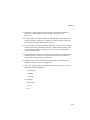
following measures:
•
Reorient or relocate the receiving antenna
•
Increase the separation between the equipment and receiver
•
Connect the equipment into an outlet on a circuit different from that to which
the receiver is connected
•
Consult the dealer or an experienced radio/TV technician for help
The user may find the following booklet prepared by the Federal Communications
Commission helpful: How to Identify and Resolve Radio-TV Interference Problems.
This booklet is available from the U.S. Government Printing Office, Washington,
D.C., 20402. Stock No. 004-00398-5.
All external cables connecting to this basic unit need to be shielded. For cables
connecting to option boards, see the option manual or installation instructions.
This digital apparatus does not exceed the Class B limits for radio noise emissions set
out in the radio interference regulations of the Canadian Department of
Communications.
This equipment is in the 2nd Class category (information equipment to be used in a
residential area or an adjacent area thereto) and conforms to the standards set by the
Voluntary Control Council For Interference by Data Processing Equipment and
Electronic Office Machines aimed at preventing radio interference in such residential
area.
When used near a radio or TV receiver, it may become the cause of radio interference.
Read the instructions for correct handling.
This equipment meets or exceeds requirements for safety in the U.S. (UL 1950),
Canada (CSA C22.2 No. 950), and Europe (EN 60950/IEC 950) with Nordic
requirements.
This equipment meets or exceeds the ergonomic requirements of ZH1/618 and is
certified to bear the GS mark by TUV Rheinland of Taiwan Ltd.
Contents
About This Guide
x
Chapter 1. Product Description
1-1
Introduction .................................................................................................. 1-1
Features ........................................................................................................ 1-1
Configurations .............................................................................................. 1-3
RAID Overview............................................................................................ 1-4
RAID Levels................................................................................................. 1-4
RAID 0 .................................................................................................. 1-4
RAID 1 .................................................................................................. 1-4
RAID 0 + 1 ............................................................................................ 1-5
RAID 5 .................................................................................................. 1-5
JBOD..................................................................................................... 1-5
Logical RAID Drive States .................................................................... 1-6
Drive Number and RAID Level ............................................................. 1-7
System Requirements ................................................................................... 1-8
Verifying the Components ............................................................................ 1-9
Chapter 2. Using the EISA Configuration Utility
2-1
Introduction .................................................................................................. 2-1
Order of Installation...................................................................................... 2-1
Running the ECU.......................................................................................... 2-2
v
Contents
Chapter 3. Installing the SWXCR-EA 1-Channel
RAID Controller
3-1
Introduction...................................................................................................3-1
Installing the 1-Channel RAID Controller .....................................................3-1
Installing the Cable and the Storage Pedestal.................................................3-3
Chapter 4. Installing the SWXCR-EB 3-Channel
RAID Controller
4-1
Introduction...................................................................................................4-1
Installing the 3-Channel RAID Controller .....................................................4-1
Installing Cables and Storage Pedestals .........................................................4-4
Chapter 5. Using the Standalone RAID Configuration
Utilities
5-1
Introduction...................................................................................................5-1
Background ...................................................................................................5-1
System Requirements ....................................................................................5-2
Before You Begin...................................................................................5-2
Files Contained on the Diskette ..............................................................5-3
Invoking the Utilities.....................................................................................5-4
Invoking the Utilities on Intel Systems ...................................................5-4
Invoking the Utilities on AXP System ....................................................5-5
Exiting the Utilities .......................................................................................5-7
Configuring the RAID Subsystem .................................................................5-8
Initial Configuration of the RAID Controller.........................................5-9
Using the Automatic Configuration Option.............................................5-12
Configuring the RAID Subsystem Interactively ......................................5-15
Creating a Drive Group....................................................................5-16
Understanding Drive Status .............................................................5-17
Creating a Logical RAID Drive .......................................................5-23
Defining a Hot Spare Drive..............................................................5-26
Initializing a Logical RAID Drive ..........................................................5-27
Saving the Configuration to a Diskette ...................................................5-29
Next Steps ..............................................................................................5-31
vi
Contents
Maintaining Your RAID Subsystem.............................................................. 5-32
Viewing and Updating Your Configuration Information......................... 5-33
Printing Your Configuration Information ............................................... 5-36
Checking Drive Information .................................................................. 5-38
Checking Logical RAID Drive Consistency (Parity Check) ................... 5-40
Adding a Hot Spare Drive after Initial Configuration ............................. 5-42
Failing a Drive....................................................................................... 5-43
Manual Rebuild of a Drive (Reconstruction).......................................... 5-45
Viewing the Bad Blocks on a Drive ....................................................... 5-47
Making a Drive Optimal ........................................................................ 5-48
Restoring the Subsystem Configuration from a Diskette......................... 5-49
Formatting the Drive.............................................................................. 5-50
Updating the BIOS................................................................................. 5-51
Updating the Firmware .......................................................................... 5-52
Updating the Firmware on an AXP System ............................................ 5-53
Chapter 6. Troubleshooting and Service Information
6-1
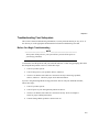
Introduction .................................................................................................. 6-1
Overview of Subsystem Indicators................................................................ 6-1
Storage Pedestal Status Indicators (SBBs).............................................. 6-1
Pedestal Status ....................................................................................... 6-2
Power Supply LEDs............................................................................... 6-2
Drive SBB Status LEDs ......................................................................... 6-6
Troubleshooting Your Subsystem ................................................................. 6-9
Before You Begin Troubleshooting........................................................ 6-9
Troubleshooting Techniques .................................................................. 6-10
Understanding Messages and Error Recovery......................................... 6-17
Removal and Replacement ........................................................................... 6-25
Replacing a Drive SBB .......................................................................... 6-25
Replacing a Power Supply SBB ............................................................. 6-28
Replacing a Primary Pedestal (Nonredundant) Power Supply.......... 6-29
Replacing a Redundant Power Supply............................................. 6-30
Replacing a Blower................................................................................ 6-31
Replacing the SWXCR Controller.......................................................... 6-34
Replacing the Controller (and Swapping the EEPROM).................. 6-35
vii
Contents
Appendix A. Specifications
A-1
Input Power Requirements.............................................................................A-1
Power Units...................................................................................................A-1
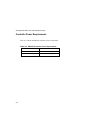
Controller Power Requirements.....................................................................A-2
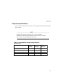
Physical Specifications..................................................................................A-3
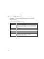
Environmental Specifications ........................................................................A-4
SBB Environmental Stabilization ..................................................................A-6
Appendix B. Illustrated Parts List
B-1
Appendix C. MS-DOS Verification Procedure
C-1
Verifying the Subsystem under MS-DOS.......................................................C-1
Using the Controller under Windows V3.1 ....................................................C-2
Figures
1-1. Logical RAID Drive State Diagram........................................................1-6
3-1. Jumper Location on the 1-Channel Controller ........................................3-2
3-2. Removing a Bezel ..................................................................................3-4
3-3. Removing the Blowers ...........................................................................3-5
3-4. Terminator and Jumper Locations ..........................................................3-6
3-5. SHELF_OK Jumper on the Terminator ..................................................3-7
3-6. SHELF_OK Jumper on the Jumper.........................................................3-8
3-7. Removing a Disk Drive or a Blank Panel ...............................................3-9
3-8. External Cable Routing ..........................................................................3-10
3-9. Cable Connections .................................................................................3-11
3-10. Device Labels.......................................................................................3-13
4-1. Jumper Location on the 3-Channel Controller ........................................4-2
4-2. Internal Cable Connections for the 3-Channel Controller .......................4-3
4-3. Removing a Bezel ..................................................................................4-5
4-4. Removing the Blowers ...........................................................................4-6
4-5. Terminator and Jumper Locations ..........................................................4-7
4-6. SHELF_OK Jumper on the Terminator ..................................................4-8
viii
Contents
4-5. SHELF_OK Jumper on the Jumper........................................................ 4-9
4-8. Removing a Disk Drive or a Blank Panel............................................... 4-10
4-9. Cable Routing........................................................................................ 4-11
4-10. External Cable Connections................................................................. 4-12
4-11. Device Labels...................................................................................... 4-14
5-1. Main Menu Screen................................................................................. 5-6
5-2. Hardware Parameters Screen ................................................................. 5-11
5-3. Automatic Configuration Screen............................................................ 5-14
5-4. New Configuration Screen..................................................................... 5-19
5-5. Define Drive Group Screen.................................................................... 5-20
5-6. Define Spare Screen .............................................................................. 5-26
5-7. Tools Screen.......................................................................................... 5-30
5-8. View/Update Configuration Screen........................................................ 5-33
5-9. View Matrix Screen............................................................................... 5-35
5-10. Device Information.............................................................................. 5-39
6-1. Power Supply LEDs............................................................................... 6-3
6-2. 3.5-inch SBB LEDs ............................................................................... 6-7
6-3. Removing a Storage Device................................................................... 6-27
6-4. Removing a Blower ............................................................................... 6-33
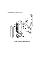
B-1. Pedestal Field Replaceable Parts ........................................................... B-2
Tables
1-1. Logical RAID States............................................................................. 1-6
6-1. Pedestal and Single Power Supply (PS) Status LEDs ............................ 6-4
6-2. Pedestal and Dual Power Supply (PS) Status LEDs............................... 6-5
6-3. Drive SBB Status LEDs........................................................................ 6-8
6-4. Troubleshooting Techniques................................................................. 6-10
A-1. BA350-KB Storage Pedestal Power Units ............................................ A-1
A-2. SWXCR Controller Power Requirements............................................. A-2
A-3. StorageWorks Storage Pedestal Physical Specifications....................... A-3
A-4. Environmental Specifications .............................................................. A-4
B-1. Illustrated Parts List for the Storage Pedestal ....................................... B-1
ix
Contents
x
About This Guide
Introduction
This guide describes how you install, configure, operate, and troubleshoot the
StorageWorks RAID Array 200 Family Subsystem. It helps to familiarize you with
all aspects of the RAID subsystem and provides a reference for questions you may
have.
Audience
This guide is written specifically for anyone who installs, configures, and operates the
StorageWorks RAID Array 200 Family Subsystem. You should be familiar with the
following:
•
System management of personal computers
•
Basic hardware installation procedures
•
System/EISA Configuration Utility
•
SCSI devices
•
Basic SCSI, RAID, and personal computer terminology (Refer to
the Acronyms and Abbreviations in this section of the guide.)
If you are not familiar with the above, contact your service representative for
installation assistance.
Related Documentation
Refer to the StorageWorks RAID Array 200 Subsystem Family Software User's Guide
for information on your operating system drive load procedure and on-line RAID
utilities.
x
About this Guide
Organization
This guide contains the following:
• Chapter 1: Product Description —Provides an overview of the StorageWorks
RAID Array 200 Subsystem including features, configurations, and system
requirements. A RAID overview is also provided.
• Chapter 2: Running the EISA Configuration Utility (ECU)—Describes how you
verify the availability of user-supplied hardware and software, how you inventory
what you received with the StorageWorks RAID Array 200 Subsystem and how
you run the ECU.
• Chapter 3: Installing the SWXCR-EA 1-Channel Controller—Describes how you
install the RAID controller in your host system and install the storage pedestal
and disk drives and connect the cables.
• Chapter 4: Installing the SWXCR-EB 3-Channel Controller—Describes how you
install the RAID controller in your host system and install the storage pedestals
and disk drives and connect the cables.
• Chapter 5: Using the Standalone RAID Configuration Utility—Includes
background information, system requirements, information on how you invoke
the utilities, configuration, and array maintenance information.
• Chapter 6: Troubleshooting and Service Information—Describes the status of the
SBB LED indicators and how you replace the components in the pedestal. It
presents a brief troubleshooting approach in the event of a pedestal component
malfunction and software errors and recovery actions for those errors.
• Appendix A: Specifications—Includes physical and environmental specifications
for the StorageWorks RAID Array 200 Subsystem Family.
• Appendix B: Illustrated Parts List—Includes the replacement part numbers and an
illustration of the StorageWorks storage pedestal.
• Appendix C: MS-DOS Verification Procedure—Contains a verification procedure
to test your RAID subsystem under the MS-DOS operating system.
xi
StorageWorks RAID Array 200 Subsystem Family
Terminology
Some of the terms you need to understand as you read this guide are defined as
follows:
Disk array: A set of disk drives and a specialized array controller. The array
controller keeps track of how data is distributed across the drives.
Drive group: A set of drives logically tied together and addressed as a single unit.
ECU: EISA (System) Configuration Utility is used to configure EISA option boards.
JBOD: Sometimes referred to as "just a bunch of disks." Each drive operates
independently and is seen by the operating system as a single drive. There is no data
redundancy in this RAID configuration.
Logical RAID drive: A section of storage space presented to the host operating
system as a single physical drive.
RAID: An acronym for a redundant array of independent (sometimes referred to as
inexpensive) disks.
RAID level: A numerical designator (0 to 5) assigned to each scheme of data
management possible in an array of drives. RAID levels supported by the SWXCR
controller include the following: RAID 0, RAID 0 + 1, RAID 1, and RAID 5.
SBB: System building block. A modular carrier plus the individual mechanical and
electromechanical interface required to mount it into a standard shelf. Any device
conforming to shelf mechanical and electrical standards is considered an SBB.
Write-Back caching: A caching policy in which the controller acknowledges that a
write operation has completed successfully before data is written to the disks. If you
choose this caching policy, you may increase the I/O performance of your RAID
subsystem, but if there is a power failure, you lose data in cache that is not yet written
to the disks.
xii
About this Guide
Write-Through caching: A caching policy in which the data is written to disk before
the controller acknowledges that a write operation is completed successfully. If you
choose this caching policy and there is a power failure, you minimize the chance of
data loss.
______________________ NOTE ____________________________
The Configuration Utility (and this document) uses the term 'MB' or
'megabyte' to mean 220 or 1,048,576 bytes. The Configuration Utility
reports only the formatted capacity.
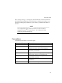
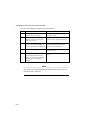
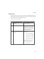
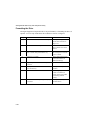
Conventions
The following conventions are used in this guide:
Convention Example
Description
bold text
Represents text or commands you must enter.
italics text
Indicates titles of manuals, chapters, sections of
chapters, new terms, and is used for emphasis.
c:\windows>
Monospaced text indicates file names, path names,
directories, or screen text.
<Enter>
Angle brackets surrounding text represents a key on
the keyboard. Used in screen displays only.
[Ctrl]+[Alt]+[Del]
A plus sign indicates that the keys shown should be
pressed at the same time.
⇒
1 234 567
A right arrow indicates a reference to additional
information.
Spaces are used in large numbers instead of commas.
xiii
StorageWorks RAID Array 200 Subsystem Family
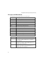
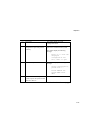
Acronyms and Abbreviations
The following acronyms and abbreviations are used in this guide:
xiv
Acronym
Meaning
BIOS
Basic input/output system
DMA
Direct memory access
DRAM
Dynamic random access memory
IDE
Integrated drive electronics
ISA
Industry standard architecture
EISA
Extended industry standard architecture
MS-DOS
Microsoft Disk Operating System
POST
Power-on self test
ROM
Read only memory
SCSI
Small computer system interface
SIMM
Single in-line memory modules
VGA
Video graphics array
Windows
Microsoft Windows application software
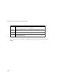
Abbreviation
Meaning
KB
A KB suffix to a numerical value indicates size in kilobytes.
For example, 640 KB, 7168 KB, and so on. A kilobyte
equals 1024 bytes.
MB
An MB suffix to a numerical value indicates size in
megabytes. For example, 1 MB, 256 MB, and so on. A
megabyte equals 1 048 576 bytes.
GB
A GB suffix to a numerical value indicates size in
gigabytes. For example, 1 GB, 256 GB, and so on. A
gigabyte equals 1 073 741 824 bytes.
About this Guide
Special Notices
Three kinds of special notices are used in this guide to emphasize specific
information.
_____________________WARNING___________________________
WARNING indicates the presence of a hazard that can cause personal
injury if the hazard is not avoided.
_____________________ CAUTION ___________________________
CAUTION indicates the presence of a hazard that might damage hardware
or corrupt software.
______________________ NOTE ____________________________
Notes provide additional information.
xv
1
Product Description
Introduction
The following topics are described in this chapter:
•
Features
•
Configurations
•
RAID overview
•
System requirements
•
Verifying the components
Features
The innovative design of the RAID Array 200 Subsystem’s SWXCR controller
incorporates all the functionality of a SCSI-based RAID controller with an EISAbased host adapter into a single, low-cost module that you can install directly into
your system. The SWXCR RAID controller supports a wide variety of RAID levels
including: 0, 1, 0 + 1, 5, and JBOD (just a bunch of disks).
This unique product, which is ideal for desktop systems or workgroup servers,
provides the power and flexibility of controller-based RAID with the scaleability of
StorageWorks packaging. The StorageWorks RAID Array 200 Subsystem Family
offers a broad choice of packaging and RAID levels that allow you to configure a
powerful and flexible high-availability storage solution that meets your unique needs.
1-1
StorageWorks RAID Array 200 Subsystem Family
The StorageWorks RAID Array 200 Subsystem Family has the following features:
1-2
•
Industry-standard EISA bus interface
•
SCSI drive interface (single-ended, 10 MB/second maximum)
•
1 or 3 SCSI channels by means of a scaleable architecture
•
Multiple SWXCR controllers (2)
•
RAID levels 0, 1, 0 + 1, 5, and JBOD are all supported
•
Cache support of 4 MB (with planned future expansion)
•
Hot spare disk drives
•
Hot swapping of disk drives
•
Mixed drive types within drive groups
Chapter 1
Configurations
The StorageWorks RAID Array 200 Subsystem Family is available in the following
configurations:
•
SWXCR-EA 1-channel unit connected to a BA350-KB storage
pedestal (or equivalent), supporting up to 7 disk drives
•
SWXCR-EB 3-channel unit connected to 1 to 3 BA350-KB storage
pedestals (or equivalent), supporting up to 21 disk drives
The following disk drives are supported:
•
RZ25L (535 MB)
•
RZ26 (1 GB - SWXD3-SA)
•
RZ26L (1GB - SWXD3-SC)
•
RZ28 (2 GB - SWXD3-SB)
Consult your supplier for additional supported disks.
A single controller can support up to eight drive groups. Following these general
rules when you configure your array:
•
Maximum number of drive groups: 8
•
Maximum number of drives in each drive group: 8
•
Maximum number of logical RAID drives: 8
1-3
StorageWorks RAID Array 200 Subsystem Family
RAID Overview
RAID (redundant array of independent disks) is a modular, integrated, end-user
solution that provides three main benefits:
•
Improved data availability
•
Improved I/O performance
•
Increased scaleability
A RAID array is a set of multiple disk drives and a specialized array controller that
manages how data is distributed across disk drives.
Data for a given file is divided into segments, which can be written across multiple
drives. A segment is a group of blocks that is continuous data which can be stored on
a disk drive. By using more than one drive, the array can provide higher data transfer
rates when compared to a single large drive. Depending on the RAID level used,
arrays can also provide redundancy to protect data availability.
As you configure your subsystem, select the RAID level appropriate for your
computing environment.
Raid Levels
RAID 0, 1, 0 + 1, 5 and JBOD are supported by the StorageWorks RAID Array 200
Subsystem Family and offer data redundancy/performance.
Raid 0
RAID 0 stripes data across the drives in the array, one segment at a time. RAID 0
offers a high I/O rate, but is a nonredundant configuration. No array parity
information is generated for reconstructing data if a drive fails.
Raid 1
RAID 1 transparently mirrors data by writing data to two drives simultaneously. This
is the simplest way of to achieve data redundancy. The cost of data storage is greater
than for a single drive, since double the disk space is required. However, RAID 1 is a
consideration for users where reliability is most important.
1-4
Chapter 1
Raid 0 + 1
RAID 0 + 1 is achieved in a multidrive RAID set by the combination of striping
mirrored sets. RAID 0 + 1 provides data redundancy and is beneficial for any critical
high-availability application. If a drive fails in a RAID 0 + 1 array, you can continue
to use the array normally since data from its mirrored drive is automatically retrieved.
Raid 5
RAID 5 combines striping (writing data across the set of drives) and storing parity
across all drives. If a drive fails in a RAID 5 array, you can continue to use the array
normally since the array controller automatically regenerates the data from the failed
drive using data and parity blocks from other operational drives. All data remains
accessible even when one drive fails.
JBOD
JBOD is an acronym for "just a bunch of drives." This mode allows a disk drive to be
accessed independently similar to using a non-RAID SCSI disk controller. This mode
does not provide any data redundancy.
1-5
StorageWorks RAID Array 200 Subsystem Family
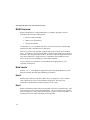
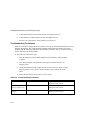
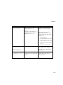
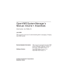
Logical RAID Drive States
The logical RAID drive or grouping of drives can be in different states. There are four
possible states as shown in Figure 1-1 and described in Table 1-1.
Figure 1-1. Logical RAID Drive State Diagram
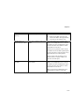
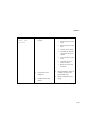
Table 1-1. Logical RAID Drive States
1-6
States
Description
Optimal
The array is operating at an optimal level. This is the
condition during normal operation.
Degraded
The logical RAID drive is operating in degraded mode. The
array is still functioning, but a single drive could have
failed. This state is only valid for RAID levels that provide
redundancy (1, 0 + 1, 3, and 5). To return the logical RAID
drive unit to optimal, rebuild (reconstruction) of the data
must be done.
Dead
The logical RAID drive unit is no longer functioning. This
is typical when two or more drives have failed.
Rebuild (Reconstruction)
The controller is currently rebuilding the logical RAID drive
unit using good data and parity information. This state is
valid only for RAID levels, 1, 0 + 1, 3, and 5 which provide
redundancy.
Chapter 1
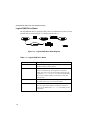
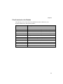
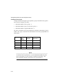
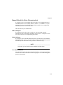
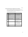
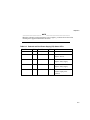
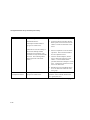
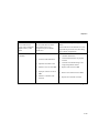
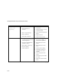
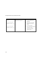
Drive Number and RAID Level
The choice of RAID level for logical RAID drives depends on the number of drives
within a drive group. The following table lists the RAID levels for drive group and
RAID level requirements.
RAID Level
0
Drives in
Drive
Group
28
Usable
Storage
Data
Redundancy
All
No
1
2
50%
Yes
0+1
38
50%
Yes
5
38
66%87%
Yes
JBOD
1
All
No
______________________ NOTE ____________________________
To maximize the I/O performance of your multichannel RAID subsystem,
locate each member of a drive group on a separate SCSI channel. This
allows the RAID controller concurrent access to the disk drives.
1-7
StorageWorks RAID Array 200 Subsystem Family
System Requirements
The StorageWorks RAID Array 200 Subsystem Family requires the following usersupplied hardware:
•
Intel or AXP-based computer system with VGA monitor and
keyboard:
- One floppy drive (3.5-inch, 1.44 MB)
- EISA backplane
- Associated system manual
- Your system ECU diskette
- EISA slot(s)
1-8
•
One for the SWXCR-EA (1-channel board)
•
Two for the SWXCR-EB (3-channel board)
•
Appropriate tools to service your computer
Chapter 1
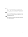
Verifying the Components
The StorageWorks RAID Array 200 Subsystem Family platform kit provides the
following components:
•
Software and documentation kit appropriate for your system and
your operating system
− Standalone RAID Array 200 Software for your system (3.5-inch diskette)
•
for AXP systems Part Number AK-Q6TFA-CA
•
for Intel systems Part Number AK-Q6TKA-CA
− On-line RAID Array 200 Software specific to your operating system
− This manual
− Software User's Guide specific to your operating system
and either
•
SWXCR-EA 1-channel controller with:
- One BA350-KB storage pedestal
- One to seven disk drives
- One 2-meter SCSI cable (BN21H-02)
or
1-9
StorageWorks RAID Array 200 Subsystem Family
•
SWXCR-EB 3-channel controller with
- One to three BA350-KB storage pedestals
- One to twenty-one disk drives
- One 2-meter SCSI cable (BN21H-02)
- One cable and bulkhead connector kit (CK-SWXCR-AA)
One internal dual-bus cable (17-03998-01)
One external Y SCSI cable (17-04000-01)
•
1-10
Optional accessories (for example, redundant power supply(ies)
(BA35X-HA)
2
Using the EISA Configuration Utility
Introduction
This chapter describes the major steps for running the EISA Configuration Utility
(ECU). Your system documentation may call this utility the System Configuration
Utility (SCU).
You use the ECU to configure your system's EISA nonvolatile memory whenever you
add or remove EISA controllers. When you boot your system, the system BIOS uses
the contents of the EISA nonvolatile memory to initialize your system's EISA
controllers.
Order of Installation
We recommended you install your subsystem in this order:
1.
Run the ECU.
2.
Install the RAID controller.
3.
Connect the cables and storage pedestal(s).
4.
Label and install the disk drives.
To install a second controller (1-channel or 3-channel), repeat the above installation
procedures. If you have two controllers, Controller 1 is the controller that is in the
EISA slot with the lowest EISA slot number and Controller 2 is the other controller.
2-1
StorageWorks RAID Array 200 Subsystem Family
Running the ECU
______________________ NOTE____________________________
At any time, you can press the ESC key to exit the ECU and begin again.
To run the ECU, follow these steps:
1.
Remove the cover from your system and locate the empty board slots. The
SWXCR controller is an EISA DMA (direct memory access) device. Refer
to your system documentation for any restrictions about installing such
devices. For more information about using the ECU on your system, refer to
your system documentation.
2.
Boot from your system ECU configuration diskette. Select the function that
configures your system and press the Enter key.
______________________ NOTE____________________________
ECUs differ from system to system. Check the procedures in this guide
before you respond to screen prompts.
2-2
Chapter 2
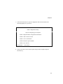
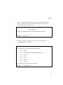
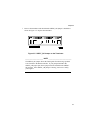
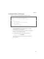
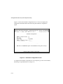
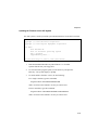
3.
Follow the instructions for system configuration until a menu similar to the
following displays on your screen.
EISA Configuration Utility
Steps in configuring your computer
STEP 1: Important EISA configuration information
STEP 2: Add or remove boards
STEP 3: View or edit details
STEP 4: Examine required details
STEP 5: Save and exit
Select=ENTER <Cancel=ESC>
4.
Choose the Add or remove boards option (Step 2 in this example) and press
the Enter key.
2-3
StorageWorks RAID Array 200 Subsystem Family
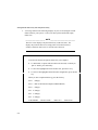
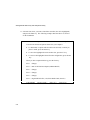
5.
A message similar to the following displays on your screen listing the current
EISA boards in your system. Look at your host system and find the empty
EISA slots.
______________________ NOTE____________________________
The ECU screen displays only the EISA slots, not the ISA slots. The
display may indicate that a slot is empty while in fact the board slot
actually contains an ISA board. You must look at the slots.
Step 2: Add or remove boards
Help=F1
Listed are the boards and options detected in your computer.
♦ To add boards or options which could not be detected, or which you
plan to install, press Insert Key.
♦ To move the highlighted board to another slot, press the F7 key.
♦ To remove the highlighted board from the configuration, press the Del
key.
When you have completed this step, press the F10 key.
Slot 1 (Empty)
Slot 2 DPT SCSI Host Bus Adapter (PM2012B2/9X)
Slot 3 (Empty)
Slot 4 (Empty)
Slot 5 (Empty)
Slot 6 (Empty)
Add=INSERT
2-4
<Remove=DEL>
<Move=F7>
<Done=F10>
Chapter 2
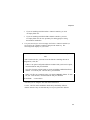
6.
•
If you are installing an SWXCR-EA 1-channel controller, you need
one empty EISA slot.
•
If you are installing an SWZCR-EB 3-channel controller, you need
two empty EISA slots in close proximity for cabling purposes during
the hardware installation.
Use your arrow keys to select an empty slot for the 1-channel controller (or
two slots for the 3-channel controller) and press the Insert key. The
following menu displays on your screen.
Step 2: Add or remove boards
Help=F1
Add
To add a board to the list, you must locate the diskette containing the boards
configuration (.CFG) file.
•
If there is an option configuration diskette included with your board or option,
insert that diskette and press ENTER.
•
CFG files for many popular boards are on the SYSTEM CONFIGURATION
diskette. To look for your .CFG file there, press ENTER.
•
Other .CFG files are contained on the .CFG FILE LIBRARY diskette. To look
for your .CFG file there, insert that diskette and press ENTER.
>Ok=ENTER<
<Cancel=ESC>
Note that you are doing the first item on the bulleted list.
Use the .CFG file on the Standalone RAID Array 200 Family Software
diskette instead of any versions that may be on your system ECU diskette.
2-5
StorageWorks RAID Array 200 Subsystem Family
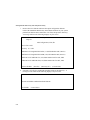
7.
Remove the ECU diskette and insert the option configuration diskette
labeled, the Standalone RAID Array 200 Software diskette for your system
platform (the diskette that contains the .CFG files) and press the Enter key.
A message similar to the following displays on your screen.
Step 2: Add or remove boards
Help=F1
Add Configuration (CFG) file
Select a file to add.
Directory: A:\*.CFG
! MLX0077.CFG Digital SWXCR-EA (1-ch) EISA RAID Cntlr (Generic)
! MLX0075.CFG Digital SWXCR-EB (3-ch) EISA RAID Cntlr (Generic)
AMLX0077.CFG SWXCR-EA (1-ch) EISA RAID Cntlr for OSF, VMS
AMLX0075.CFG SWXCR-EB (3-ch) EISA RAID Cntlr for OSF, VMS
Select=ENTER
8.
(Sort=F6)
(Directory=F7)
(Cancel=ESC)
Select the .CFG file for your RAID controller and press the Enter key. A
message screen similar to the following displays on your screen.
Destination Diskette
Insert the SYSTEM CONFIGURATION diskette.
Ok=ENTER
2-6
<Cancel=ESC>
Chapter 2
9.
Remove the Standalone RAID Array 200 Software diskette, insert the ECU
diskette, and press the Enter key. An add confirmation message, similar to
the following, displays on your screen.
Step 2: Add or remove boards
Add confirmation
Board Name: Digital SWXCR-EA (1-ch) EISA RAID Cntlr (Generic)
Ok=ENTER
<Cancel=ESC>
10. Press the Enter key to confirm the .CFG file. A message similar to the
following displays on your screen.
Add
Select an acceptable slot for the board and press ENTER.
Slot 1 (Empty)
Slot 2 DPT SCSI Host Bus Adapter (PM2012B2/9X)
Slot 3 (Empty)
Slot 4 (Empty)
Slot 5 (Empty)
Slot 6
(Empty)
The ( ) indicates an acceptable slot for the board
>Ok=Enter<
<Cancel=ESC>
2-7
StorageWorks RAID Array 200 Subsystem Family
11. Select the slot where you want to install the controller (the slot is highlighted)
and press the Enter key. The following example shows that Slot 6 is selected
for the installation.
Step 2: Add or remove boards
Help=F1
Listed are the boards and options detected in your computer.
♦ To add boards or options which could not be detected, or which you
plan to install, press the Insert key.
♦ To move the highlighted board to another slot, press the F7 key.
♦ To remove the highlighted board from the configuration, press the Del
key.
When you have completed this step, press the F10 key.
Slot 1 (Empty)
Slot 2 DPT SCSI Host Bus Adapter (PM2012B2/9X)
Slot 3 (Empty)
Slot 4 (Empty)
Slot 5 (Empty)
Slot 6 Digital SWXCR-EA (1-ch) EISA RAID Cntlr (Generic)
Add=INSERT
2-8
<Remove=DEL>
<Move=F7>
<Done=F10>
Chapter 2
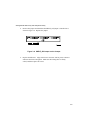
12. Press the F10 key. You return to the Steps in configuring your computer
menu. A display similar to the following appears on your screen.
EISA Configuration Utility
Steps in configuring your computer
STEP 1: Important EISA configuration information
STEP 2: Add or remove boards
STEP 3: View or edit details
STEP 4: Examine required details
STEP 5: Save and exit
Select=ENTER <Cancel=ESC>
2-9
StorageWorks RAID Array 200 Subsystem Family
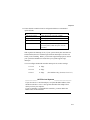
13. Select the View or edit details option (Step 3 in this example) and press the
Enter key. Scroll through the file until you find the slot number for the
controller you are installing. The information display for a 1-channel board
installation is similar to the following.
______________________ NOTE____________________________
The slot you are looking for has the "Added" identifier on the right side of
the screen display.
Slot 6 - Digital SWXCR-EA (1-ch) EISA RAID Cntlr (Generic)
Added
disk spin-up options.............................................2 disks started every 6 secsDefault
Channel 0 tag-queuing (SCSI-2)..........................Enable tag-queuing - Default
Channel 0 transfer-rate (max)..............................Synchronous, 10 MB/s (FAST) Default
BIOS (16K) Base Address...................................0CC000H - Default
Interrupt...............................................................Interrupt 11 (edge) - Default
Edit=ENTER
<Edit Resources=F6>
<Advanced=F7>
The display for a 3-channel board installation differs slightly.
2-10
<Done=F10>
Chapter 2
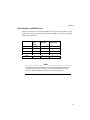
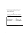
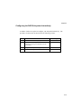
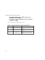
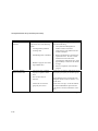
14. Ensure that the controller board is configured with these recommended
option defaults.
Option
Default Setting
Disk spin-up options
2 disks started every 6 seconds - Default
Tag-queuing
Enable tag-queuing - Default
Transfer-rate
Synchronous, 10 MB/s (FAST) - Default
BIOS
For AXP systems, disable this option.
For Intel systems, enable this option. See the
note below.
With regard to the Interrupt (level), if your system already has more than one
board installed, the ECU should assign a different interrupt level to the new
board you are installing. Before you select the edge/interrupt option, consult
your system documentation to ensure that your system supports edge
interrupts.
You can configure the RAID controller interrupt levels to these settings:
11 Level
11 Edge
12 Level
12 Edge
15 Level
15 Edge
(For NetWare only, do not use Level 15.)
_______________ NOTE for Intel Systems _____________________
If your boot device is an EISA adapter, verify that the BIOS address of the
SWXCR controller is set to a value greater than that of the adapter from
which you boot your computer.
If you are installing a second SWXCR controller, you must disable the
BIOS on the second controller.
2-11
StorageWorks RAID Array 200 Subsystem Family
15. Press the F10 key. You return to the Steps in configuring your computer
menu. A menu similar to the following displays on your screen.
EISA Configuration Utility
Steps in configuring your computer
STEP 1: Important EISA configuration information
STEP 2: Add or remove boards
STEP 3: View or edit details
STEP 4:
Examine required details
STEP 5:
Save and exit
Select=ENTER <Cancel=ESC>
2-12
Chapter 2
16. Select the Save and exit option (Step 5 in this example) and press the Enter
key. Your screen displays a message similar to the following.
EISA Configuration Utility
Help=F1
Your configuration file has been saved, and if possible a backup SYSTEM.SCI file
has been made on the current drive.
To complete your configuration, you must do one of the following:
If you need to install boards or change switches and jumpers on boards already
installed, turn off your computer and do so.
If you want to test your system or install an operating system, press ENTER to
restart your computer, run the configuration utility again, and select the appropriate
main menu item.
If you are finished configuring, remove the SYSTEM CONFIGURATION diskette if
it is in drive A and press ENTER to restart your computer.
Ok=ENTER
17. Follow the directions on your screen displays until you save and exit the
ECU.
18. Remove the diskette and turn off the host system.
•
If you are installing an SWXCR-EA 1-channel controller, go to
Chapter 3 to continue with the hardware installation of your
subsystem.
•
If you are installing an SWXCR-EB 3-channel controller, go to
Chapter 4 to continue with the hardware installation of your
subsystem.
2-13
3
Installing the SWXCR-EA 1-Channel
RAID Controller
Introduction
This chapter describes the major steps for installing the 1-channel controller:
•
Installing the 1-channel controller in the host system.
•
Installing the storage pedestal and the disk drives, and connecting the cables.
Installing the 1-Channel RAID Controller
_____________________ CAUTION ___________________________
To avoid static damage, follow adequate antistatic procedures when you
handle the RAID controller.
To install the RAID controller, follow these steps.
1.
Refer to your host system manual for general instructions on installing
adapters.
2.
Unpack the RAID controller.
3-1
StorageWorks RAID Array 200 Subsystem Family
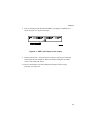
3.
Confirm that the jumper at JP5 (onboard termination enabled) is installed.
See Figure 3-1. If the jumper is not present, you must insert one or notify
your supplier.
Internal
Channel 0
Cache Module
JP5
External
Channel 0
MR0221
Figure 3-1. Jumper Location on the 1-Channel Controller
4.
Install the RAID controller in the slot you selected when you ran the ECU.
3-2
Chapter 3
Installing the Cable and the Storage Pedestal
This section describes the cabling and installation procedure for the storage pedestal.
If you are installing a system with embedded disk drives, refer to that system's
documentation for instructions on cabling.
______________________ NOTE ____________________________
If the SCSI port is set to the default values of synchronous and 10 MB/s
(FAST), the total cable length cannot exceed three meters (two meters for
the cable and one meter for the storage pedestal).
To install the storage pedestal and make the cable connections, follow these steps.
1.
Unpack the BN21H-02 cable and the storage pedestal. Place the storage
pedestal where it is to be used. Label it Pedestal 0.
2.
Unlock and open the front and rear bezel doors. See Figure 3-2.
3-3
StorageWorks RAID Array 200 Subsystem Family
3.
Remove the front and rear bezels from the storage pedestal by pushing down
on the locking tabs at the bottom of each bezel. See Figure 3-2.
REAR
BEZEL
TOP
BEZEL
FRONT
BEZEL
DOOR
KEY
LOCKING
TAB
MR0224
Figure 3-2. Removing a Bezel
3-4
Chapter 3
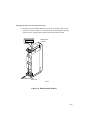
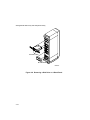
4.
At the rear of the storage pedestal, use a Phillips screwdriver to remove the
safety screw in each corner of the two blowers. See Figure 3-3.
5.
To remove a blower, press the locking tabs on the sides of the blower and
pull the blower straight out to disconnect it.
Figure 3-3. Removing the Blowers
3-5
StorageWorks RAID Array 200 Subsystem Family
6.
Remove the second blower to see the whole backplane.
The appearance of the backplane depends upon the version of the
StorageWorks storage pedestal that you have. After you remove the blowers,
determine if your pedestal has jumper pins next to the Slot 2 connector on the
rear of the backplane. See blowup of detail on Figure 3-4.
Figure 3-4. Terminator and Jumper Locations
•
If jumper pins are not present on the backplane and the terminator and
jumper are installed as shown in Figure 3-4, go to Step 7.
•
If jumper pins are present, install a jumper in the Shelf_OK_External_Cables
position as in Figure 3-4.
3-6
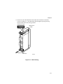
Chapter 3
7.
Remove the terminator and check that the SHELF_OK jumper is installed as
shown in Figure 3-5. Replace the terminator.
Figure 3-5. SHELF_OK Jumper on the Terminator
______________________ NOTE ____________________________
The SHELF_OK jumper allows the fault signals from the storage pedestal
to be fed back to the RAID controller. If your jumper/terminator has
SHELF_OK jumper pins, then a jumper must be installed in the SHELFOK position. If this SHELF_OK jumper is missing, insert one or notify
your supplier.
3-7
StorageWorks RAID Array 200 Subsystem Family
8.
Remove the jumper and check that the SHELF_OK jumper is installed on as
shown in Figure 3-6. Replace the jumper.
Figure 3-6. SHELF_OK Jumper on the Jumper
9.
Replace both blowers. Align each blower connector with its power connector
and insert the blower straight in. Make sure the locking tabs are firmly
seated, and then replace the screws.
3-8
Chapter 3
10. Remove the blank panels (and any disk drives) from the front of the storage
pedestal. See Figure 3-7.
DRIVE
LOCKING TABS
BLANK PANEL
MR0223
Figure 3-7. Removing a Disk Drive or a Blank Panel
3-9
StorageWorks RAID Array 200 Subsystem Family
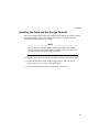
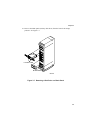
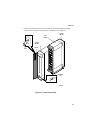
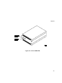
11. Thread one end of the BN21H-02 cable under the rear handle of the storage
pedestal, as shown in Figure 3-8. Then thread the cable through the opening
at the top of the storage pedestal and toward the front of the pedestal.
Viewed from Front
BN21H-02 or
Y-Cable
JA1
To JA1
To RAID Controller
Rear View
MR0226
Figure 3-8. External Cable Routing
3-10
Chapter 3
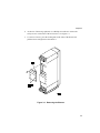
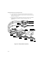
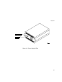
12. Loop the cable down below the divider plate and connect it to connector JA1
(upper-left connector when viewed from the front) on the storage pedestal.
See Figure 3-9.
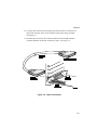
13. Insert the other end of the cable into the connector for the RAID controller
(external channel 0) at the back of the host system. See Figure 3-9.
Figure 3-9. Cable Connections
3-11
StorageWorks RAID Array 200 Subsystem Family
14. Thread the female end of the ac power cable under the handle of the storage
pedestal. Insert it into the ac receptacle on the ac distribution unit.
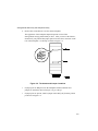
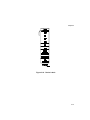
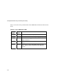
15. After you consult the pedestal configuration diagram (Figure 3-10), label the
disk drives with the following information:
• Device type
• Channel
• SCSI ID
For example:
Dev: RZ26L
CH: 0
ID: 1
3-12
Chapter 3
Figure 3-10. Device Labels
3-13
StorageWorks RAID Array 200 Subsystem Family
______________________ NOTE____________________________
These rules apply to device addresses for the storage pedestal:
•
The default device addresses use the slot number in the storage
pedestal, as shown in Figure 3-10.
•
The available addresses for each slot in the storage pedestal are 0
through 6.
16. Install the labeled drives in the storage pedestals using the configuration
layout shown in Figure 3-10.
17. To support the hot swap option, verify that all power supply SBBs
(BA35X-HA) are Rev. L01 or later.
18. Connect the other end of the ac power cable to an ac power source.
19. Replace the front and rear bezel doors.
20. Power up the storage pedestal.
21. Power up the host system.
3-14
Chapter 3
22. On Intel systems with the BIOS enabled, you can confirm proper installation
of the RAID controller when you see a message similar to the following
during the boot process.
SWXCR BIOS Version x.x
Digital Equipment Corporation
SWXCR Firmware Version x.x
SWXCR RAM: x Mbytes
If you do not get these messages or the installation aborts, refer to Chapter 6 of this
manual for troubleshooting and service information.
At this point, you used the ECU to inform your host system about the new RAID
controller (Chapter 2) and you added the RAID controller (this chapter). Now turn to
Chapter 5 to configure the RAID controller to use the disk devices.
3-15
4
Installing the SWXCR-EB 3-Channel
RAID Controller
Introduction
This chapter describes the major steps for installing the SWXCR-EB 3-channel
controller:
•
Installing the RAID controller in the host system
•
Installing the storage pedestals and disk drives, and connecting the cables
Installing the 3-Channel RAID Controller
_____________________ CAUTION ___________________________
To avoid static damage, follow adequate antistatic procedures when you
handle the RAID controller.
To install the RAID controller, you follow these steps.
1.
Refer to your host system manual for general instructions on installing
adapters.
2.
Unpack the RAID controller.
4-1
StorageWorks RAID Array 200 Subsystem Family
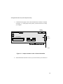
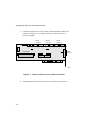
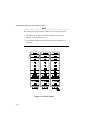
3.
Confirm that jumpers at JP3, JP4, and JP5 (onboard termination enabled) are
installed. See Figure 4-1. If a jumper is missing, you must insert one or
notify your supplier.
Internal
Channel 2
JP3
Internal
Channel 1
Internal
Channel 0
JP4
Cache Module
JP5
External
Channel 0
MR0217
Figure 4-1. Jumper Locations on the 3-Channel Controller
4.
4-2
Install the RAID controller in the slot you selected when you ran the ECU.
Chapter 4
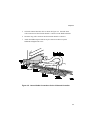
5.
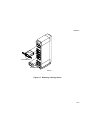
Orient the internal dual-bus cable as shown in Figure 4-2. Insert the short
cable connector into the internal channel 1 connector on the RAID controller.
6.
Insert the long cable connector into the internal channel 2 connector.
7.
Attach the bulkhead panel with its 68-pin connector to the host system
bulkhead and tighten the screw.
Figure 4-2. Internal Cable Connections for the 3-Channel Controller
4-3
StorageWorks RAID Array 200 Subsystem Family
Installing Cables and Storage Pedestals
This chapter describes the cabling and installation procedure for the storage pedestals.
If you are installing a system with embedded disk drives, refer to that system's
documentation for cabling instructions.
______________________ NOTE____________________________
If the SCSI port is set to the default values of synchronous and 10 MB/s
(FAST), the total cable length cannot exceed three meters (two meters for
the cable and one meter for the storage pedestal).
To install the storage pedestals and make the cable connections, you follow these
steps.
1.
Unpack the Y-cable, the BN21H-02 2-meter cable, and the storage pedestals.
Place the storage pedestals where they are to be used and label them.
______________________ NOTE____________________________
Depending on your configuration, you can install one, two, or three
storage pedestals on the RAID controller. Label the first pedestal as
Pedestal 0. Any other pedestals are labeled Pedestal 1 and Pedestal 2,
respectively. Pedestal 0 connects to Channel 0, Pedestal 1 connects to
Channel 1, and Pedestal 2 connects to Channel 2.
2.
4-4
Unlock and open the front and rear bezel doors. See Figure 4-3.
Chapter 4
3.
Remove all front and rear bezel doors from the storage pedestals by pushing
down on the locking tabs at the bottom of each bezel. See Figure 4-3.
REAR
BEZEL
TOP
BEZEL
FRONT
BEZEL
DOOR
KEY
LOCKING
TAB
MR0224
Figure 4-3. Removing a Bezel
4-5
StorageWorks RAID Array 200 Subsystem Family
4.
At the rear of the storage pedestal, use a Phillips screwdriver to remove the
safety screw in each corner of each blower. See Figure 4-4.
5.
To remove a blower, press the locking tabs on the sides of the blower and
pull the blower straight out to disconnect it.
Figure 4-4. Removing the Blowers
4-6
Chapter 4
6.
Remove the second blower to see the whole backplane.
The appearance of the backplane depends upon the version of the
StorageWorks pedestal that you have. After you remove the blowers,
determine if your pedestal has jumper pins next to the Slot 2 connector on the
rear of the backplane. See blowup of detail on Figure 4-5.
Figure 4-5. Terminator and Jumper Locations
•
If jumper pins are not present on the backplane and the terminator and the
jumper are installed as shown in Figure 4-5, go to Step 7.
•
If jumper pins are present, install a jumper in the Shelf_OK_External_Cables
position as in Figure 4-5.
4-7
StorageWorks RAID Array 200 Subsystem Family
7.
Remove the terminator and check that the SHELF_OK jumper is installed as
shown in Figure 4-6. Replace the terminator.
Figure 4-6. SHELF_OK Jumper on the Terminator
______________________ NOTE____________________________
The SHELF_OK jumper allows the fault signals from the storage pedestal
to be fed back to the RAID controller. If your jumper/terminator has
SHELF_OK jumper pins, then a jumper must be installed in the SHELFOK position. If this SHELF_OK jumper is missing, insert one or notify
your supplier.
4-8
Chapter 4
8.
Remove the jumper and check that the SHELF_OK jumper is installed on as
shown in Figure 4-7. Replace the jumper.
Figure 4-7. SHELF_OK Jumper on the Jumper
9.
Replace both blowers. Align each blower connector with its power connector
and insert the blower straight in. Make sure that the locking tabs are firmly
seated. Then replace the screws.
10. Remove the disk drives and any blank panels from the front of storage
pedestals. See Figure 4-8.
4-9
StorageWorks RAID Array 200 Subsystem Family
DRIVE
LOCKING TABS
BLANK PANEL
MR0223
Figure 4-8. Removing a Disk Drive or a Blank Panel
4-10
Chapter 4
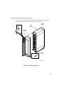
11. Thread one end of the BN21H-02 cable under the rear handle of Pedestal 0,
as shown in Figure 4-9. Then thread the cable through the opening at the top
and toward the front of the storage pedestal.
Viewed from Front
BN21H-02 or
Y-Cable
JA1
To JA1
To RAID Controller
Rear View
MR0226
Figure 4-9. Cable Routing
4-11
StorageWorks RAID Array 200 Subsystem Family
12. Loop the BN21H-02 cable down below the divider plate and connect the
cable to connector JA1 (upper-left connector when viewed from the front) on
Pedestal 0. See Figure 4-9.
13. Insert the other end of the BN21H-02 cable into the connector for the RAID
controller (External Channel 0) at the back of the host system. See
Figure 4-10.
Figure 4-10. External Cable Connections
4-12
Chapter 4
14. Thread the Y-cable connector labeled Channel 1 under the rear handle of
Pedestal 1, and through the opening at the top of the pedestal. See
Figure 4-9.
15. Loop the Channel 1 connector down below the divider plate of Pedestal 1 and
connect the cable to connector JA1 (upper-left connector when viewed from
the front) on the storage pedestal. See Figure 4-10.
16. If you are using a third storage pedestal, thread the Y-cable connector labeled
Channel 2 under the rear handle of Pedestal 2, and through the opening at the
top of the storage pedestal. See Figure 4-9. If you are not using Pedestal 2,
coil the Channel 2 cable.
17. Loop the Channel 2 connector down below the divider plate of Pedestal 2 and
connect the cable to connector JA1 (upper-left connector viewed from the
front) on the storage pedestal. See Figure 4-10.
18. Insert the 68-pin connector into the external channel 1/2 connector on the
bulkhead of the host system. See Figure 4-10.
19. After you consult the pedestal configuration diagram (Figure 4-11), label the
disk drives with this information:
• Device type
• Channel
• SCSI ID
For example:
Dev: RZ26L
CH: 0
ID: 1
4-13
StorageWorks RAID Array 200 Subsystem Family
______________________ NOTE____________________________
The following rules apply to device addresses for the storage pedestal:
•
The default device addresses use the slot number in the storage
pedestal, as shown in Figure 4-11.
•
The available addresses for each slot in the storage pedestal are 0
through 6.
Figure 4-11. Device Labels
4-14
Chapter 4
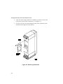
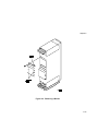
20. Insert the drives into the storage pedestal according to the layout shown in
Figure 4-11.
21. To support the hot swap option, verify that all power supply SBBs
(BA35X-HA) are Rev. L01 or later.
22. Insert the optional redundant power supply SBBs into the designated slots.
See Figure 4-11.
23. Thread the female end of the ac power cable under the handle of each storage
pedestal. Connect the cable to the ac receptacle on the ac distribution unit.
The ac extension cable is not used in this configuration.
24. Connect the other end of the ac power cable to an ac power source.
25. Replace the front and rear bezel doors.
26. Power up the storage pedestal.
27. Power up the host system.
28. On Intel systems with the BIOS enabled, you can confirm proper installation
of the RAID controller when you see a message similar to the following
during the boot process.
SWXCR BIOS Version x.x
Digital Equipment Corporation
SWXCR Firmware Version x.x
SWXCR RAM: x Mbytes
If you do not get a similar message, refer to Chapter 6 of this manual for
troubleshooting and service information.
At this point, you used the ECU to inform your host system about the new RAID
controller (Chapter 2) and you added the RAID controller (this chapter). Now turn to
Chapter 5 to configure the RAID controller to use the disk devices.
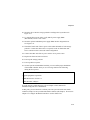
4-15
5
Using the Standalone RAID
Configuration Utilities
Introduction
This chapter contains the following topics:
•
Background information
•
System requirements
•
Invoke the utilities
•
Exit the utilities
•
Initial configuration of the SWXCR RAID controller
•
Configuration information
•
Array maintenance information
Background
Use the Standalone RAID Array 200 Software to configure and maintain your
StorageWorks RAID Array 200 Subsystem.
Before you can use your RAID subsystem, you must configure the disks into drive
groups, and then configure logical RAID drives (see the terminology section of this
guide) at a particular RAID level using the Standalone RAID Array 200 Software.
Once you complete the configuration process, the configuration data is saved in the
RAID controller's flash EEPROM/NVRAM (the controller's memory). However, you
should also save the configuration data to a file on a diskette so that you can restore it
in case the controller is ever replaced.
5-1
StorageWorks RAID Array 200 Subsystem Family
System Requirements
You must have the following to run the utility:
•
An Intel or Alpha AXP system with a VGA monitor and a keyboard
•
One floppy disk drive (3.5-inch, 1.44 MB)
•
SWXCR controller installed and all disk drives connected and powered on.
Before You Begin
Make a backup copy of the Standalone RAID Array 200 Software diskettes (the Intel
x86 or AXP diskette, whichever you are using on your system) on a PC using this
procedure.
5-2
1.
Copy the diskette using the MS-DOS diskcopy command (see your MS-DOS
manual for detailed instructions on how to use this command).
2.
Label the new diskette and store the original diskette in a safe place.
Chapter 5
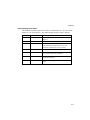
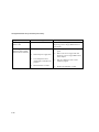
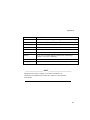
Files Contained on the Diskette
The following is a list of the files for the SWXCR controller contained on your
Standalone RAID Array 200 Software diskette:
File Names
Description
RELEASE.TXT
Release information
!MLX0077 CFG
SWXCR-EA 1-channel ECU configuration file (Generic)
!MLX0075.CFG
SWXCR-EB 3-channel ECU configuration file (Generic)
AMLX0077 CFG
SWXCR-EA 1-channel ECU configuration file for OSF, OpenVMS
AMLX0075.CFG
SWXCR-EB 3-channel ECU configuration file for OSF, OpenVMS
!!CFG.NDX
Configuration file for ECU
SWXCRMGR.EXE
Standalone RAID Configuration Utility
SWXCRFW.EXE
SWXCR Firmware Download Utility
SWXCRFW.nnn (version)
SWXCR Firmware
SWXCRBIO.EXE
SWXCR BIOS Download Utility
SWXCRBIO.nnn (version)
SWXCR BIOS
DACD.EXE
Diagnostic stub (reserved for future use)
5-3
StorageWorks RAID Array 200 Subsystem Family
Invoking the Utilities
You can invoke the utilities on an Intel system or an AXP system. If you have an
Intel system, refer to the "Invoking the Utilities on Intel Systems" section of this
chapter. If you have an AXP system, refer to the "Invoking the Utilities on AXP
Systems" section of this chapter.
Before you power on and boot your system to invoke the utilities, be sure that all
storage pedestals are powered on.
When you invoke the utilities, the software checks the status of each drive. If the
drive status changes after you invoke the utilities (for example, if a drive fails or if
you remove a drive), the change does not display until the next time you invoke the
utilities.
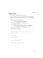
Invoking the Utilities on Intel Systems
1.
Insert the Standalone RAID Array 200 Software Vx.x for Intel
Systems diskette in your floppy drive and boot from that drive.
2.
Enter this command at the prompt:
A:\SWXCR> SWXCRMGR
After checking the drives, the system displays the main menu of the
utilities as shown in Figure 5-1.
5-4
Chapter 5
Invoking the Utilities on AXP Systems
Consult your AXP system documentation to invoke this boot menu.
ARC Multiboot DEC Version 2.07
Copyright (c) 1993 Microsoft Corporation
Copyright (c) 1993 Digital Equipment Corporation
Boot Menu
Boot Windows NT
Boot an alternate operating system
Run a program
Supplementary menu ...
Use the arrow keys to select, then press Enter.
1.
Insert the Standalone RAID Array 200 Software Vx.x for AXP
Systems diskette into your floppy drive.
2.
To select the Run a program option, use the arrow key and press the
Enter key. The system displays a prompt.
3.
To run the utilities from the A: drive, enter the following:
Program to Run: A:SWXCRMGR
After checking the drives, the system displays the main menu as
shown in Figure 5-1.
5-5
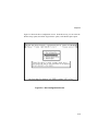
StorageWorks RAID Array 200 Subsystem Family
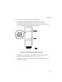
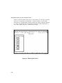
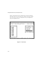
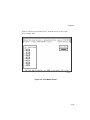
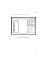
Figure 5-1 shows the main menu screen. From this menu, you can invoke each
of the utilities. As you move the cursor from one option to the next, the
message window changes to display a message for the highlighted option.
MR0229
Figure 5-1. Main Menu Screen
5-6
Chapter 5
______________________ NOTE ____________________________
You can use the Enter key or the Return key interchangeably.
From this point on, the description of the utilities is the same for both Intel
and AXP systems.
Use the arrow keys to move through the menu, highlight your selection,
and then press the Enter key to select the option you want. From the main
menu, you can type the highlighted letter (usually the first letter of the
menu item) for your selection and then press the Enter (or Return) key.
Exiting the Utilities
At any time, you can exit the utilities by pressing the ESC key from the main menu.
The system prompts you to confirm that you want to exit the utilities. Select Yes to
return to the MS-DOS prompt.
5-7
StorageWorks RAID Array 200 Subsystem Family
Configuring the RAID Subsystem
The following tasks are involved in configuring your subsystem.
•
Initial installation of the subsystem requires setting the these options:
−
Fault Management
−
Battery Backup
You only need to set these options once. The settings become effective when
the system is rebooted.
•
There are two ways to configure the RAID Subsystem. Depending upon your
specific hardware configuration and needs, select one of these:
−
Automatic Configuration
You can only use this option if your RAID subsystem has between
three and eight drives and you want all of the drives configured as
either RAID 5 or JBOD.
−
Interactive Configuration
You use this option to configure your RAID subsystem with the
utilities. During the procedure, you use the utilities to perform the
following steps:
5-8
•
Configure one or more drive groups
•
Configure one or more logical RAID drives
−
Specify RAID levels
−
Specify caching policy
•
Initialize drives with RAID parity information
•
Specify a hot spare drive if you choose to include one
Chapter 5
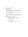
Initial Configuration of the RAID Controller
At the initial installation, set the Fault Management and Battery Backup options. You
only need to set these options once.
For the Fault Management option, consider the following:
•
If your RAID controller is connected to StorageWorks pedestals or to shelves that
support fault management, enable this option.
•
If your RAID controller is connected to non-StorageWorks storage shelves or
directly to disk drives by means of ribbon cables, disable this option.
Since the Battery Backup option is not supported, verify that it is disabled.
5-9
StorageWorks RAID Array 200 Subsystem Family
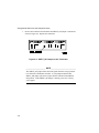
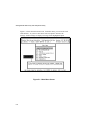
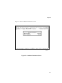
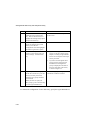
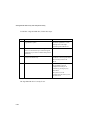
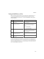
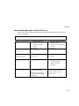
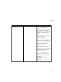
To set the Fault Management option, proceed as follows.
Step
1
Action
Select the Advanced Functions
option from the main menu.
Result
The system displays an Edit/View
Parameter menu.
2
Use the arrow keys to highlight the
Hardware Parameters option and
press the Enter key.
The system displays the current status
of both options, similar to Figure 5-2.
3
Use the arrow keys to highlight the
option and to change the status of
an option, then press the Enter key.
The system toggles the option
between Enable and Disable each
time you press the Enter key.
4
Press the ESC key.
You return to the Edit/View
Parameter menu.
5
Press the ESC key again.
The system returns you to the main
menu.
If you changed the status of an
option, save the current status by
selecting the Yes option at the
prompt.
______________________ NOTE____________________________
Any change to the Fault Management setting becomes effective the next
time the system is rebooted.
5-10
Chapter 5
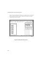
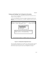
Figure 5-2 shows the Hardware Parameters screen.
MRO235
Figure 5-2. Hardware Parameters Screen
5-11
StorageWorks RAID Array 200 Subsystem Family
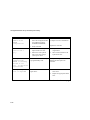
Using the Automatic Configuration Option
You can use this procedure if you have three to eight drives in your subsystem that
you want to configure as either RAID 5 or JBOD. Use the procedure for automatic
configuration as described below.
If you plan to define one of your drives as a hot spare drive, you must do the
following:
1.
Exit the utility.
2.
Remove the drive you want to designate as your hot spare drive.
3.
Reinvoke the utility.
4.
Use the procedure for automatic configuration below.
5.
Go to the section of this chapter called, "Adding a Hot Spare after Initial
Configuration."
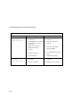
Step
1
2
Action
Select the Automatic Configuration
option from the main menu.
Result
The system displays a warning
message saying that a valid
configuration exists and if you
proceed, you will destroy it. There is
also a confirmation window.
Select Yes if you want to proceed.
If you select No, the system returns
you to the main menu.
The system displays a window with
this message:
Do you want Write
Cache enabled?
Continued on the next page.
5-12
Chapter 5
Step
3
Action
Select No to set the cache policy to
Write Through (the recommended
policy).
Result
The system displays a window with
this message at the bottom of the
screen:
Saving
configuration,
please wait ...
The system then displays a screen
with your system configuration
information. See Figure 5-3.
4
Press any key to return to the main
menu.
5
From the main menu, select the
Initialize Logical Drive option
described later in this chapter.
5-13
StorageWorks RAID Array 200 Subsystem Family
Figure 5-3 shows the Automatic Configuration screen. This screen displays the
configuration information that results from using the Automatic Configuration
option.
MRO231
Figure 5-3. Automatic Configuration Screen
To complete the automatic configuration of your subsystem, go to the section entitled,
Initializing a Logical RAID Drive, on Page 5-27.
5-14
Chapter 5
Configuring the RAID Subsystem Interactively
A number of tasks are required to configure your subsystem interactively. The
procedures for these tasks are described in the following sections.
Step
1
Action
Create one or more drive groups.
See Page
P. 5-18
2
Create one or more logical RAID drives,
including specifying their RAID levels and
cache policy.
P. 5-23
3
Designate a hot spare drive (optional)
P. 5-25
4
Initialize each logical RAID drive.
P. 5-27
5-15
StorageWorks RAID Array 200 Subsystem Family
Creating a Drive Group
A single controller can support up to eight drive groups. Remember these general
rules when you configure your array:
•
Maximum number of drive groups: 8
•
Maximum number of drives in each drive group: 8
•
Maximum number of logical RAID drives: 8
The choice of RAID level for logical RAID drives depends on the number of drives
within a drive group. This table shows the RAID levels for drive group/RAID level
requirements.
RAID Level
0
Drives in
Drive
Group
28
Usable
Storage
Data
Redundancy
All
No
1
2
50%
Yes
0+1
38
50%
Yes
5
38
66%87%
Yes
JBOD
1
All
No
______________________ NOTE____________________________
To maximize the I/O performance of your multichannel RAID subsystem,
locate each member of a drive group on a separate SCSI channel. This
allows the RAID controller concurrent access to the disk drives.
5-16
Chapter 5
Understanding Drive Status
The SWXCR controller assigns a drive status to each SCSI device. The drive status
changes as you use the utilities. The utilities display the drive status as follows.
Display
FLD
Drive Status
Failed
Meaning
The device failed due to errors or you manually
failed it.
FMT
Formatting
The device is formatting.
HSP
Hot spare
The device is configured as a hot spare (within a
redundant RAID configuration) for use in an
automatic rebuild in the event of a failure.
OPT
Optimal
The device is on line and configured for use.
RDY
Ready
The device is spun up and ready to be used by
the controller, but is not configured.
UNF
Unformatted
The device was being formatted and you halted
the format operation.
WOL
Write Only
The device is being rebuilt and is in a write-only
mode.
5-17
StorageWorks RAID Array 200 Subsystem Family
To begin the configuration process, first you create a drive group.
______________________ NOTE____________________________
The total capacity of a drive group is determined by the member with the
least capacity. If you are uncertain about the size of a particular drive, use
the Device Information option on the Define Drive Group screen to check
the size before you create a drive group.
If you select a drive for the drive group by mistake or you want to redefine a drive
group, use the Cancel Group option and begin again. However, you can only use the
Cancel Group option until you arrange the drive groups. Once you use the Arrange
Group option, the Cancel Group option does not function.
Step
1
2
Action
Select the New Configuration
option from the main menu.
Result
The system displays a screen like
Figure 5-4. The Define Drive Group
function is highlighted.
Press the Enter key to select the
Define Drive Group option.
The system displays a drive matrix
that shows the drives connected to the
adapter and the status of each. See
Figure 5-5. The Create Group
function on the screen's menu is
highlighted.
Continue to the next step.
5-18
Chapter 5
Figure 5-4 shows the New Configuration screen. From this screen, you can select the
Define Group option, the Define Logical Drive option, or the Define Spare option.
MRO230
Figure 5-4. New Configuration Screen
5-19
StorageWorks RAID Array 200 Subsystem Family
Figure 5-5 shows the Define Drive Group screen. From this screen, you can create a
drive group, cancel a group you created, arrange the drive group(s), and display
information about your drive groups.
MRO232
Figure 5-5. Define Drive Group Screen
5-20
Chapter 5
Step
3
4
Action
Press the Enter key to select the
Create Group option on the menu.
Result
The cursor moves to the drive matrix.
Position the cursor on the drive you
want to add to the drive group and
press the Enter key.
The system adds that drive to the drive
group. The RDY (ready) status next
changes to OPT (optimal). The drive
is assigned a group letter and a
sequence number.
Add other drives to the drive group
by repeating this step.
If you plan to specify a hot spare
drive, leave at least one drive of
equal or greater capacity to the other
drives in the RDY (ready) state.
If you assign all the physical devices
to drive groups, the system
automatically highlights the Arrange
Group option and you can continue at
Step 7.
5
To declare the end of the drive
group, press the ESC key.
The system returns to the Group
Definition screen as shown in
Figure 5-5.
6
Repeat Steps 3 through 5 of this
procedure for each additional drive
group.
Each new drive group is assigned a
different group letter and the drives in
the group are assigned a sequence
number.
When you have set up all your drive
groups, go on to the next step to
arrange the groups.
Continued on the next page.
5-21
StorageWorks RAID Array 200 Subsystem Family
Step
7
Action
If the cursor is not on the Group
Definition menu, press the ESC
key. Then use the arrow keys to
highlight the Arrange Group option
and press the Enter key.
Result
The cursor moves to the drive pictorial
on this screen.
NOTE: In Step 8, when all drive
groups are arranged, the system
returns you to the New
Configuration menu and highlights
the Define Logical Drive option.
8
9
Use the arrow keys to move the
cursor to a drive in the group you
want to arrange. Press the Enter
key.
Repeat Step 8 for all drive groups.
NOTE: Be careful not to press the
ESC key because you lose the
remaining drive groups and must
recreate them.
•
If you have arranged all drive
groups, see the next section of this
chapter, "Creating a Logical RAID
Drive" for a description of the steps
for this procedure.
•
If you have not arranged all drive
groups, the drive group and size
information for arranged drive
groups is displayed in the table at
the lower-right side of the screen,
as shown in Figure 5-5.
As each drive group is arranged, its
information is added to the table.
When you have set up all your
drive groups, go on to the next step
to create logical RAID drives.
To continue the configuration of a new disk array, specify the logical RAID drives.
5-22
Chapter 5
Creating a Logical RAID Drive
A logical RAID drive is presented to the host operating system as one physical drive.
To the operating system, there is no difference between a controller logical RAID
drive and a single physical drive on a conventional disk controller. A logical RAID
drive consists of part or all of any drive group.
______________________ NOTE ____________________________
For a RAID 5 configuration, the controller must use some of the space for
parity information. When you specify the size, calculate the usable space
according to this formula:
usable space = total space * (N-1/N) where N is the number of drives in
the drive group.
Step
1
Action
Select the Define Logical Drive option.
Result
A screen shows the drive groups
available for selection as logical RAID
drives.
2
Select the Create Logical Drive option.
A pop-up window displays the RAID
levels available for that logical RAID
drive. Unavailable levels are still
visible but you cannot select them.
3
Select the RAID level for the logical
RAID drive.
A pop-up window displays the usable
size of the logical RAID drive.
4
Enter a size for the new logical RAID
drive.
The status block is updated with the
RAID level and size of the logical
RAID drive.
5
Confirm that you want to create this
logical RAID drive. Select Yes.
The system adds the logical RAID
drive to the list at the lower-left of the
screen.
Continued on the next page.
5-23
StorageWorks RAID Array 200 Subsystem Family
Step
6
7
Action
Repeat this procedure for up to eight
logical RAID drives, or until all the
capacity of the selected drive group is used.
Result
Each new logical RAID drive is
added to the table on the lower-left
of the screen.
Choose a caching policy. The default
policy is Write-Thru (Through).
The cursor moves to the right-hand
column of the list of logical RAID
drives and highlights the Write-Thru
of the first logical RAID drive.
To change the cache policy, select the
Toggle Write Policy option on the menu.
NOTE: Digital strongly recommends a
Write-Through caching policy to eliminate
the chance of data loss due to a power
failure. See the Terminology section in the
About this Guide portion of this manual.
8
Press the Enter key to toggle the caching
policy to the alternative: Write-Back.
Use the arrow keys to move to another
logical RAID drive.
9
5-24
When you are finished with the cache
policy, press the ESC key once.
You return to the Logical Drive
Definition menu.
10
Press the ESC key again.
You return to the New Configuration
menu.
11
Press the ESC key again.
The system displays a confirmation
window.
12
Select Yes in the confirmation box.
The configuration is saved to the
flash EEPROM/NVRAM. The
system returns you to the main
menu. You can now initialize the
logical RAID drives.
Chapter 5
Defining a Hot Spare Drive
If your business cannot tolerate data loss or downtime due to drive failures, you
should keep a drive available in the array as a hot spare for automatic rebuilds.
Follow this procedure to create a hot spare drive.
Step
1
Action
Select the View Update option from
the main menu.
Result
The system displays the
View/Update Configuration menu as
shown in Figure 5-8.
2
Select the Define Spare option.
The system displays the Define
Spare menu as shown in Figure 5-6.
3
Use the arrow keys to select the
drive you want to define as a spare
and press the Enter key.
The system changes the drive status
to HSP (hot spare).
4
If you select the wrong drive or
decide that you do not want a hot
spare drive, press the Enter key
again.
The status of the drive returns to its
previous status.
5
Press the ESC key.
The system displays a confirmation
window that asks if you want to save
your configuration.
6
Select Yes.
The system saves your configuration
and returns you to the main menu.
5-25
StorageWorks RAID Array 200 Subsystem Family
Figure 5-6 shows the Define Spare screen. In this example, you can only see Channel
0 because it corresponds to an SWXCR-EA 1-channel controller. If your RAID
subsystem uses an SWXCR-EB 3-channel controller, the display would show channels
0, 1, and 2. Note that the drive in Target ID 4 of channel 0 in this example shows a
drive status of HSP. This drive is defined as the hot spare.
MRO234
Figure 5-6. Define Spare Screen
5-26
Chapter 5
Initializing a Logical RAID Drive
Before you can use a logical RAID drive, it must be initialized to ensure consistent
RAID parity information. For RAID levels that provide redundancy, this step is
crucial to ensure that the RAID parity information is consistent from the beginning.
_____________________ CAUTION ___________________________
Do not initialize a logical RAID drive if it has valid data. Initialization
overwrites and destroys all data.
After you initialize a logical RAID drive, do not change or rearrange the physical
drives or cables. Otherwise, all data in the drive group can be lost.
5-27
StorageWorks RAID Array 200 Subsystem Family
To initialize a logical RAID drive, follow these steps.
Step
1
Action
From the main menu, select the Initialize
Logical Drive option.
Result
The system displays the
Initialize Logical Drive screen,
showing each of the eight
possible logical RAID drives.
2
You can initialize more than one logical RAID
drive. Use the arrow keys to select the logical
RAID drives you want to initialize and press the
Return key.
3
Use the arrow keys to select the Start button
and press the Return key.
The system warns you that the
initialization of the logical RAID
drives destroys data on the
drives.
4
Select Yes in the confirmation box.
The status bar gradually fills as
the initialization process
completes and asks you to
continue by pressing any key
when done.
The system saves the
configuration and returns you to
the main menu.
The logical RAID device is ready for use.
5-28
Chapter 5
Saving the Configuration to a Diskette
Digital strongly recommends that you save your configuration to a file on a diskette at
this point. In the event that your controller fails, you need a backup of your
configuration file in order to restore your original configuration on your new
controller.
You can use a formatted diskette or save the file to the diskette that you are using to
run the utilities.
To save the configuration, proceed as follows.
Step
1
Action
Insert the diskette.
Result
2
From the main menu, select the
Tools option.
The system displays the Tools
menu. See Figure 5-7.
3
To save the configuration
information in a file, select the
Backup/Restore conf option.
The system displays the
Backup/Restore conf menu.
4
Select Backup from the
Backup/Restore conf menu.
The system prompts for the name
of the file.
5
Enter an appropriate file name with
up to eight characters not including
the file extension. For example:
The system creates the file in your
current directory.
PCNAME_1
6
Press the ESC key to exit.
The system returns to the main
menu.
5-29
StorageWorks RAID Array 200 Subsystem Family
Figure 5-7 shows the Tools screen. From this screen, you can review the bad
block table, list the error count, format a drive, change a drive status to optimal,
fail a drive, back up or restore your configuration, clear your configuration, or
print your configuration to a file.
MRO233
Figure 5-7. Tools Screen
5-30
Chapter 5
Next Steps
You can either repeat the previous procedure to create additional logical RAID
drives or exit the utilities and boot your operating system to initialize the logical
RAID drives you just created.
For information about using the utilities under your operating system, refer to
the StorageWorks RAID Array 200 Subsystem User's Guide specific to your
operating system.
If you are using an Intel system, refer to Appendix C for a verification procedure
that you can use to test your subsystem.
5-31
StorageWorks RAID Array 200 Subsystem Family
Maintaining Your RAID Subsystem
To maintain your RAID subsystem, use the utilities to do the following:
•
View the current configuration
•
Print the current configuration
•
Check drive information
•
Check logical RAID drive consistency
•
Add a hot spare after initial configuration
•
Fail a physical drive
•
Rebuild a drive
View bad block information
Make a drive optimal
•
Restore a configuration from diskette
•
Format a drive
•
Update the firmware
•
Update the BIOS
The procedures for these tasks are described in the following sections.
5-32
Chapter 5
Viewing and Updating Your Configuration Information
You can use the View/Update Configuration option from the main menu to view or
change an existing configuration.
To view your configuration, select the View/Update Configuration option from the
main menu. The system displays the View/Update Configuration menu as shown in
Figure 5-8.
MRO236
Figure 5-8 . View/Update Configuration Screen
The View/Update Configuration screen contains some of the same options as the New
Configuration menu described in the section, "Configuring the RAID Subsystem."
However these options all operate on the current configuration to modify it.
5-33
StorageWorks RAID Array 200 Subsystem Family
This menu's unique option is the View Logical Matrix option. Use this option to
display the current configuration before you make any changes.
Step
1
Action
Select the View Logical Drive
Matrix option.
Result
The system displays the View matrix screen
as shown in Figure 5-9.
2
Press the ESC key.
The system displays the View/Update
Configuration screen as shown in Figure 5-8.
3
Press the ESC key to exit.
The system returns you to the main menu.
Display
FLD
5-34
Drive Status
Failed
Meaning
The device failed due to errors or you manually failed it.
FMT
Formatting
The device is formatting.
HSP
Hot spare
The device is configured as a hot spare (within a redundant
RAID configuration) for use in an automatic rebuild in the
event of a failure.
OPT
Optimal
The device is on line and configured for use.
RDY
Ready
The device is spun up and ready to be used by the
controller, but is it not configured.
UNF
Unformatted
The device was being formatted and you halted the format
operation.
WOL
Write Only
The device is being rebuilt and is in write-only mode.
Chapter 5
Figure 5-8 shows the View Matrix screen. From this screen you can see the
drives and their status.
MRO238
Figure 5-9 . View Matrix Screen
5-35
StorageWorks RAID Array 200 Subsystem Family
Printing Your Configuration Information
To print your existing configuration, use the Print Configuration option as follows.
Step
1
2
3
4
5-36
Action
Select the Tools option from the
main menu.
Result
The system displays the Tools screen as
shown in Figure 5-7.
Select the Print Configuration
option.
The system displays this prompt:
Enter an eight-character file name
(including the file extension) for
the log file that saves the
configuration information. Then
press the Enter key.
The system displays this message:
Select yes to save the information
to the file you specified, or select
No and press the ESC key to
return to the previous menu.
When you select Yes, the system displays this
message:
5
Press the ESC key to return to the
main menu.
6
To exit the utilities, press the ESC
key again.
7
Select Yes to return to the MSDOS prompt.
8
Print the file you saved to your
printer.
Enter File Name
Existing File, if any
will be overwritten!
Saved configuration print
file. Press any key to
continue.
The system prompts you to confirm that you
want to exit the utilities.
The file is similar to the following example.
Chapter 5
Example of a Print Configuration File
*************************************************************
Digital Disk Array Controller - Configuration Utility
*
*
*
Version 2.20
*************************************************************
CONFIGURATION INFORMATION OF :
==============================
1 Channel - 7 Target
SWXCR
in Slot 3
Firmware version 1.97
DRIVE GROUP INFORMATION :
===========================
Number of drive groups = 1
Group 0 : [0:0]
LOGICAL RAID DRIVE INFORMATION :
=================================
Number of Logical RAID Drives = 1
Log. Drv # Phy. Size
Raid Level Eff. Size
========
=========
0
========
4004 MB
5
========
3003 MB
Write Policy
============
Write Thru
5-37
StorageWorks RAID Array 200 Subsystem Family
Checking Drive Information
To check your drive information, use the Device Information option as follows.
Step
1
Action
Select the View/Update
Configuration option from the
main menu.
Result
The system displays the View/Update
Configuration screen as shown in Figure 5-8.
2
Select the Define Drive Group
option.
The system displays the Define Drive Group
screen as shown in Figure 5-5.
3
Select the Device Information
option from the Group Definition
portion of the screen.
The cursor moves to the Drive Matrix portion
of the screen.
4
Use the arrow keys to move the
cursor to the drive for which you
want information and press the
Enter key.
The system displays the drive information at
the lower-right of the screen as shown in
Figure 5-10.
5
Continue to select drives and
display their information. When
you finish, press any key to stop
displaying information, but to
continue to use this menu.
The system displays the View/Update
Configuration screen.
Press the ESC key to return to the
View /Update Configuration
screen.
6
5-38
Press the ESC key again to return
to the main menu.
The system displays the main menu.
Chapter 5
Figure 5-10 shows the Device Information for a selected disk.
MRO240
Figure 5-8 . Device Information
5-39
StorageWorks RAID Array 200 Subsystem Family
Checking Logical RAID Drive Consistency (Parity Check/Repair)
Use the Parity Check/Repair utility to check a logical RAID drive for the consistency
of the RAID parity information. Run this utility after a power failure or a system
crash to verify the integrity of parity information on logical RAID drives in the array.
______________________ NOTE____________________________
This utility is only available for redundant RAID levels (for example,
RAID 1, RAID 0 + 1, and RAID 5).
This utility reads the data from the logical RAID drives and computes the expected
parity information for each series of blocks. The computed parity information is then
compared with the parity information stored on the disks. Any discrepancies between
the two are flagged.
5-40
Chapter 5
To check the consistency of a logical RAID drive, follow these steps.
Step
1
Action
Select the Parity Check option on the main
menu.
Result
The system displays the Parity
Check screen and lists the
logical RAID drives.
2
Select a logical RAID drive to check the
consistency of the parity information on the
logical RAID drive.
The parity check status bar in
the center of the screen displays
the status of the consistency
check. The bar gradually fills as
the process completes.
3
If the utility detects any fault with the disk, the
system displays a message. Follow the
instructions at the bottom of the screen.
4
To fix inconsistent RAID parity information on a
logical RAID drive, enter Yes when queried by
the utility.
NOTE: If you choose not to fix inconsistent
RAID parity information, your data may not be
regenerated correctly if a drive fails.
5
When the bar displays 100%, press any key to
continue.
The system returns you to the
main menu.
5-41
StorageWorks RAID Array 200 Subsystem Family
Adding a Hot Spare Drive after Initial Configuration
If your business cannot tolerate data loss or downtime due to drive failures, you
should keep a drive available in the array as a hot spare for automatic rebuilds.
If you plan to define one of your drives as a hot spare drive, you must do the
following:
1.
Exit the utility.
2.
Insert the drive you want to designate as your hot spare drive.
3.
Invoke the utility.
4.
Use the procedure for creating a hot spare below.
5.
Save your new configuration to a diskette as described on Page 5-29.
Step
1
5-42
Action
Select the View/Update Configuration
option from the main menu.
Result
The system displays the View /Update
Configuration menu as shown in Figure 5-8.
2
Select the Define Spare option from the
View/Update Configuration menu.
The system displays the Define Spare menu as
shown in Figure 5-6.
3
Use the arrow keys to select the drive
you want to define as a spare and press
the Enter key.
The system changes the drive status to HSP (hot
spare).
4
If you select the wrong drive or decide
that you do not want a hot spare drive,
press the Enter key again.
The status of the drive returns to its previous
status.
5
Press the ESC key.
The system displays a confirmation window that
asks if you want to save your configuration.
6
Select Yes.
The system saves your configuration and returns
you to the main menu.
Chapter 5
Failing a Drive
A drive can fail due to errors on the device or because you manually failed it. If the
utility records errors on a drive in your array, you may want to manually fail and then
replace the drive before a permanent failure occurs.
To fail a drive, proceed as follows.
Step
1
Action
Select the Tools option from the
main menu.
Result
The system displays the Tools menu
as shown in Figure 5-7.
2
Select the Kill Drive option.
The system displays the drive
matrix. The drives you can fail are
highlighted. The drives you cannot
select are grayed out (drives with a
status of RDY (ready) or FLD
(failed) cannot be selected.
3
Use the arrow keys to select the
drive you want to fail and press the
Return key.
The system displays a message
similar to this:
Killing an OPTIMAL
drive will change
its state to FAILED
and will stop reads
and writes to that
drive. This could
change the state of
the logical drive.
The system displays this message
while the utility fails the drive.
Press any key to
continue
Continued on the next page.
5-43
StorageWorks RAID Array 200 Subsystem Family
Step
4
5-44
Action
Press any key.
Result
The system displays a confirmation
window.
5
Select Yes.
The system spins down the drive.
The status of the drive changes to
FLD (failed).
6
Pull out the drive and replace it with
a new drive.
The system automatically rebuilds
on the new drive.
Chapter 5
Manual Rebuild of a Drive (Reconstruction)
A rebuild is a process of recreating data on a new drive in a configuration with a
redundant RAID level (for example, RAID 1, RAID 0 + 1, and RAID 5). If your
logical RAID drive was configured with a RAID level that does not support data
redundancy, all data is lost if a drive fails.
There are three ways to rebuild a drive.
With a Hot Spare
If you defined a spare drive, when a SCSI drive fails, the RAID controller
automatically starts to rebuild the information on a hot spare. A hot spare is set to
write only so data is not corrupted during the rebuild.
With a Hot Swap
If you replace a drive while the RAID subsystem is operating and you enabled the
Fault Management option (as described earlier in this chapter) the RAID controller
automatically starts the rebuild. This operation is called a hot swap.
______________________ NOTE ____________________________
It may take up to one minute for the automatic rebuild to begin.
For a Manual Rebuild
You can rebuild a SCSI drive that you failed manually or a drive that could not be
rebuilt because either an automatic rebuild is in progress or the Fault Management
option was not enabled.
5-45
StorageWorks RAID Array 200 Subsystem Family
______________________ NOTE____________________________
To minimize the chance of data loss due to a second drive failure, upon
detection of a drive failure, replace the drive as soon as possible.
To manually rebuild data of a failed physical drive (if you have not defined a hot
spare drive), follow these steps.
Step
1
2
Action
Remove the failed drive from the RAID
subsystem and replace it with a new drive.
Result
Go to the main menu and select the Rebuild
option.
The system displays a screen
with the drive matrix, showing
the drives and their status.
The new drive is recognized by
the system and spun up. The
status of the new drive remains
FLD (failed) until the rebuild
begins.
5-46
3
Select the drive to be rebuilt. The drive you
select must have a FLD (failed) status.
The rebuild status bar gradually
fills as the process completes.
4
When the bar displays 100%, press any key to
continue.
The system returns you to the
main menu.
Chapter 5
Viewing the Bad Blocks on a Drive
During a rebuild, the bad block table receives entries from a rebuild with errors. If
you are using the Rebuild option to rebuild a disk and the rebuild fails, the drive
remains in the WOL (write only) state. You can use the Bad Block Table option to
view the bad blocks.
Step
1
2
Action
Select the Tools option from the
main menu.
Result
The system displays the Tools menu as
shown in Figure 5-7.
Select the Bad Block Table option
from the Tools menu.
The system displays the View Bad Block
Table menu at the lower-left side of the
screen. You can select one of these
options:
•
View Rebuild BBT
•
View Write Back BBT
3
Select the View Rebuild BBT.
The system displays bad blocks on the
logical RAID drive including the block
number and the number of consecutive bad
blocks encountered.
4
Press any key to return to the View
Bad Block Table menu.
The system clears Rebuild Bad Block
Table once it is read. You can save it to a
file.
5
Press the ESC key to return to the
main menu.
The system displays the main menu.
If you have Write-Back cache enabled, the bad block table receives information on
any errors encountered during a write. You can use the View Write Back BBT option
on the View Bad Block Table menu to view this information. This option works like
the View Rebuild BBT described above.
5-47
StorageWorks RAID Array 200 Subsystem Family
Making a Drive Optimal
In some circumstances described in the Troubleshooting Your Subsystem section of
Chapter 6, you may have to use the Make Optimal option to change the state of a
drive from failed (FLD) to (OPT) optimal. If you use this method to change the state
of a drive instead of using the Rebuild option, the drive may contain faulty data.
_____________________CAUTION __________________________
When you use this option, ensure the integrity of the data stored on all
logical RAID drive(s) that use the failed drive. For example, do the
following:
• For drives with a redundant RAID level (RAID 1, 0 + 1, or 5), use the
Parity Check option from the Tools menu.
• Run an operating system file integrity check.
• Run a data integrity check of your files (application-specific).
If corrupted files are detected, you have to restore data from backups.
To change the status of a drive to optimal, use these steps.
Step
1
5-48
Action
Select the Tools option from the
main menu.
Result
The system displays the Tools menu as
shown in Figure 5-7.
2
Select the Make Optimal option
from the Tools menu.
The cursor moves to the Drive Matrix.
3
Use the arrow keys to move the
cursor to the drive you want to
change to optimal status and press
the Enter key.
The system changes the state of the FLD
(failed) drive to OPT (optimal).
4
Press the ESC key to return to the
main menu.
The system displays the main menu.
Chapter 5
Restoring the Subsystem Configuration from a Diskette
To restore your configuration information due to RAID controller replacement, use
the file containing the configuration you saved on a diskette (the procedure for saving
your configuration information was described earlier in this chapter).
To restore the configuration, proceed as follows.
Step
1
Action
Insert the diskette.
Result
2
Select the Tools option from the
main menu.
The system displays the Tools
menu as shown in Figure 5-7.
3
Select the Backup/Restore option.
The system warns you of the
result.
4
Press any key to continue.
The system prompts you for a file
name.
5
Enter the name of the file with the
configuration information.
The system asks if you want to
restore the configuration.
6
Select Yes.
The system reports that the file has
been restored and asks you again to
confirm that you want to restore
the configuration.
7
Select Yes.
The system reports that the
contents of the file has been
written to the RAID controller's
memory. When the process is
complete, the system reports
success.
8
Press the ESC key to exit from the
display.
5-49
StorageWorks RAID Array 200 Subsystem Family
Formatting the Drive
All Digital Equipment Corporation drives are preformatted, so formatting the drives is
optional. You can only format those drives that have not been configured.
Step
1
5-50
Action
From the main menu, select the Tools option.
Result
The system displays the
Tools menu as shown in
Figure 5-7.
2
Select the Format Drive option.
The cursor moves to the
first available drive in the
matrix.
3
Use the arrow keys to highlight the drive you
want to format and press the Enter key.
The system warns you of
the consequences and asks
you to confirm.
4
Select Yes to confirm.
Drive status changes from
UNF (unformatted) to
FMT (formatting).
5
Repeat Steps 3 and 4 for each drive you want
to format.
6
When you have selected one or more drives,
press the ESC key.
The system asks you to
confirm.
7
Select Yes to confirm.
Formatting begins. When
a disk is formatted, its
status changes from FMT
(formatting) to RDY
(ready).
8
When the format is complete, press any key
to continue.
The system returns you to
the main menu.
Chapter 5
Updating the BIOS
You do not need to update the BIOS for AXP systems.
To update your BIOS on an Intel system, insert the standalone RAID Array 200
Software Vx.x for Intel Systems diskette in your floppy drive and boot from that
drive.
For a single controller, type this command:
A:\SWXCR>SWXCRBIO SWXCRBIO.nnn
where nnn refers to the BIOS version you want to load.
For two controllers, type this command:
A:\SWXCR>SWXCRBIO SWXCRBIO.nnn SWXCRBIO.nnn
where nnn refers to the BIOS version you want to load.
The system displays these messages.
SWXCR BIOS Write Utility Ver. 1.0
-
January 4, 1993
Mylex Corporation
Writing EEPROM ...
Verifying EEPROM ...
SWXCR BIOS Write Completed
Press any key to reboot the system
5-51
StorageWorks RAID Array 200 Subsystem Family
Updating the Firmware
To update your controller's firmware, proceed as follows.
Updating the Firmware on an Intel System
To update your firmware on an Intel system, insert the standalone RAID Array 200
Software Vx.x for Intel Systems diskette into your floppy drive and boot from that
drive.
For a single controller, type this command:
A:\SWXCR>SWXCRFW SWXCRFW.nnn
where nnn refers to the firmware version you want to load.
For two controllers, type this command:
A:\SWXCR>SWXCRFW SWXCRFW.nnn SWXCRFW.nnn
where nnn refers to the firmware version you want to load.
The system displays these messages:
****************************************************************
SWXCR Firmware Download Utility (V2.21, Jun 02, 1993)
****************************************************************
This utility is used to upgrade the firmware on the SWXCR
controller.
****************************************************************
SWXCR Controller supporting 7 targets per channel found at slot 3
5-52
Chapter 5
Updating the Firmware on an AXP System
For AXP systems, consult your AXP system documentation to invoke this boot menu.
ARC Multiboot DEC Version 2.07
Copyright (c) 1993 Microsoft Corporation
Copyright (c) 1993 Digital Equipment Corporation
Boot Menu
Boot Windows NT
Boot an alternate operating system
Run a program
Supplementary menu ...
Use the arrow keys to select, then press Enter.
1.
Insert the Standalone RAID Array 200 Software Vx.x for AXP
Systems diskette into your floppy drive.
2.
To select the Run a program option, use the arrow key and press the
Enter key. The system displays a prompt.
3.
To run the utilities from the A: drive, do the following:
For a single controller, type this command:
Program to Run: A:SWXCRFW SWXCRFW.nnn
where nnn refers to the firmware version you want to load.
For two controllers, type this command:
Program to Run: A:SWXCRFW SWXCRFW.nnnSWXCRFW.nnn
where nnn refers to the firmware version you want to load.
5-53
StorageWorks RAID Array 200 Subsystem Family
The system displays the following messages.
****************************************************************
SWXCR Firmware Download Utility (V2.21, Jun 02, 1993)
****************************************************************
This utility is used to upgrade the firmware on the SWXCR
controller.
****************************************************************
SWXCR Controller supporting 7 targets per channel found at slot 3
5-54
6
Troubleshooting and Service Information
Introduction
This chapter describes the following:
•
Overview of subsystem indicators
•
Troubleshooting subsystem problems
•
Removal and replacement
Overview of Subsystem Operations
The following sections provide an overview of operations for the StorageWorks components.
Review these sections before you start troubleshooting.
Storage Pedestal Status Indicators (SBBs)
!"#$&%$'(")(*"#+$,-%
++.!)(*"
.)
/#0 $213
54'-
6*"17"#(.*5
8$ / '9"):9"(.!!!+':
;'<#=>6',
.#'!'
0 (? !9",.!!! 0 7#'<#>@ACBDE++ F#
"17+ $+G#'6)HI=>!!%+'9?+J)*5 '!K)*5; / 2 !'6L*ML
)"!))"# +N$5>*"+ '!(-%
+&.!)E'
,
O% .!!*)$'!)H!
O9P
+#"!)"! !>@CABQ#'!'
0 =
6-1
StorageWorks RAID Array 200 Subsystem Family
Pedestal Status
29"(.!!! 0 @ABJ-1 #+ / $* &+D
O9"=!! / 9",
$2)
(%!$!!
!)< >*"++J
O !
9"(.!!! 0
!)< ! !*
!*, ")
2 !>)
L !< '* = 29"
.!!! 0 @ACBD-+#'*"
$
%!$2!
6*"17!"6=!!>@CABD
+#'* %
.!&!9?!"!>%!$!%+9?&J* #+$',*"*).!
9"(.!!! 0 %
.!+
• / '9"-!) / '"1
• F*,+6!.!!9"8! / '"1
•
Power Supply LEDs
(. *"
!""17&!$!>
$.(% / $? !
/ '9"),
?$!9"
.!!!+' /#0 '+J
!$29"(.!!! 0 F)"@ACBD(
F(9??+ F.!) =
2"%$@ACB '!'
0 8 !
6
$.,
?$! F6@CABQ#'!'
0 -$
9",.!!! 0 $.=
6-2
Chapter 6
Figure 6-1. Power Supply LEDs
6-3
StorageWorks RAID Array 200 Subsystem Family
•
•
! "? !'"%$@AB '(6: / $?$2!
/ 9",
O !9"
.!!!+',
)%$.!*5$6+N!)" 0 =
!"? !'"%$@AB '(% %$:"&$!"(
!
/ 9"((
9"(.!!! 0 '
!!%$.!*5 '#+ !)" 0 =
Tables 6-1 and 6-2 describe the power supply LED codes.
Table 6-1. Pedestal and Single Power Supply (PS) Status LEDs
Shelf Status
6-4
Power Supply Status
Indicates
On
On
Normal. Pedestal functioning
properly.
Off
On
Bad blower unit. Replace faulty
blower.
Off
Off
Power supply bad. Replace faulty
supply.
Chapter 6
_______________________ NOTE_____________________________
When the pedestal is equipped with two power supplies, you must observe the LEDs
on both power supplies to determine the status.
Table 6-2. Pedestal and Dual Power Supply (PS) Status LEDs
Shelf Status
PS1
Shelf Status
PS2
Indicates
On
On
On
On
Normal.
Off
On
Off
On
Blower unit bad.
Replace blower.
Off
Off
On
On
PS1 bad.
Replace faulty supply.
On
On
Off
Off
PS2 bad.
Replace faulty supply.
Off
Off
Off
Off
PS1 and/or PS2 bad.
Possible input power
problem.
6-5
StorageWorks RAID Array 200 Subsystem Family
Drive SBB Status LEDs
F.!) 9-$= M&!*5 #' #'<6=!! <#!
8$9 @CAB &#'*"
)
$
#'!'
0 $
.,%!$N!< '* =!!>
.,* &$'!(%!$!>@ACBD,
)
+'?+C
/ ' =!!>@ACBD8
F<62 #)>
!=
2"%$@ACB E$F)"!H#8$N!< *">
F*)$'<+ 0 @CAB O,8% '
6+
•
9?!"? ! <#',
*5 '<#=
2; F#@ACB EM
1 / ")H#'8 ! ;'<#%
.!+@ACB O+#'* ,
")
•
*"#+ '?9?!"?+!'( EM* "!!9?!" 0 . .!?$ 0 "1 #:
!$
! +1 / '"%!%$
F#& 8!13
'H =
6-6
Chapter 6
Figure 6-2. 3.5-inch SBB LEDs
6-7
StorageWorks RAID Array 200 Subsystem Family
Table 6-3 shows the activity and fault status for the SBB LEDs and indicates what the status
means.
Table 6-3. Drive SBB Status LEDs
Activity
Status
Fault
Status
Indicates
On
Off
Normal: Device is operating properly.
Off
Off
Normal: Device is inactive and operating properly.
On
On
Error: Device is hung up.
Replace the device.
6-8
Off
On
Error: Device is inactive and spun down. Replace the
device.
On/Off
Flashing
Error: Device is active and spinning down due to the
fault. (When you turn the system on, brief flashing is
normal.)
Chapter 6
Troubleshooting Your Subsystem
This section contains troubleshooting information to correct problems that may be easy to fix. It
also directs you to the appropriate documentation for further troubleshooting if needed.
Before You Begin Troubleshooting
_______________________ NOTE_____________________________
Always turn off the power to your system before you turn off the power to
your storage pedestal(s).
To determine what the problem with your SWXCR controller is when using packaging other than
the StorageWorks pedestal or shelves, follow these steps:
1.
Turn off your host system.
2.
Turn off the power to your pedestal, shelves, and drives.
3.
Check to see that the SCSI cables are connected correctly to the storage pedestal,
shelves, and drives. Check for proper SCSI cable termination.
If you are using the StorageWorks storage pedestal or shelves with your SWXCR controller,
follow these steps:
1.
Turn off your host system.
2.
Turn off power to your StorageWorks pedestal or shelves.
3.
Check to see that the SCSI cables are connected correctly. Refer to Chapters 3
and 4, for proper cabling instructions.
4.
Turn the StorageWorks pedestal or shelves back on.
6-9
StorageWorks RAID Array 200 Subsystem Family
5.
Verify that all the drives LEDs flash on when you turn the power on.
6.
Verify that the two LED indicators on the power supplies are on.
7.
Turn on your system and see if the problem is now resolved.
Troubleshooting Techniques
When the controller or subsystem does not operate correctly, use the information in this section to
diagnose the problem. The troubleshooting techniques described do not identify all possible
problems with the SWXCR controller or StorageWorks pedestal or shelves, nor do the corrective
actions suggested correct all problems.
To use Table 6-4, follow these steps:
1.
Note the symptoms of the problem displayed by the controller, storage pedestal,
or shelves.
2.
See if the description of the problem in the Symptom column in Table 6-4 is
similar to yours.
3.
Check the conditions for that symptom in the Possible Cause(s) column. If more
than one possible cause is given, check all of the possible causes in the order
listed.
4.
Follow the directions in the Action(s) to Take column.
Table 6-4. Troubleshooting Techniques
Symptom
Drive SBB Fault Light is
On
Possible Cause(s)
Drive failed.
Action(s) to Take
Replace drive using the Replacing a Drive
SBB section of this chapter.
Drive SBB Fault and
Activity Lights are On
Drive failed or is hung.
Replace drive using the Replacing a Drive
SBB section of this chapter.
Drive SBB Fault Light is
Flashing
Drive failed and is spinning down.
Replace drive using the Replacing a Drive
SBB section of this chapter.
Continued on the next page.
6-10
Chapter 6
Symptom
Replaced Drive has not
Spun Up
Possible Cause(s)
Drive not seen by the controller.
Multiple Drives in
Pedestal/Shelf are Failed
There was a pedestal or shelf power
failure.
Action(s) to Take
• Manually rebuild the drive.
•
Remove drive SBB, wait 20 seconds,
reinsert drive SBB. Wait approximately
one minute for the rebuild to start.
Check the monitor log to verify the power
failure or for multiple drive errors. Invoke
the utilities and select the Bad Block option
on the Tools menu of the utilities to check
for bad blocks on the drives.
Restore power to pedestal or shelf. Invoke
the utilities and use the Make Optimal option
on the Tools menu to change the state of any
FLD (failed) drives to OPT (optimal).
See the caution under the Making Drives
Optimal section in Chapter 5 before you
proceed to use that option.
Multiple Logical Drives
are Dead
There was a pedestal or shelf
power failure.
Check the monitor log to verify the power
failure or for multiple drive errors. Invoke
the utilities and select the Bad Block option
on the Tools menu of the utilities to check
for bad blocks on the drives.
Refer to the action for "Multiple Drives in
Pedestal/Shelf are Failed" on this table.
Continued on the next page.
6-11
StorageWorks RAID Array 200 Subsystem Family
Symptom
Drive has a WOL Status•
Possible Cause(s)
Drive is being rebuilt.
Action(s) to Take
• No action required.
•
•
Rebuild failed drive.
•
Invoke the utilities and select the Bad
Block option on the Tools menu of the
utilities to check for bad blocks on the
drives.
•
Shelf failure occurred resulting in
the need for multiple rebuild
operations to be initiated. (The
controller can only rebuild one disk
at a time. The remaining failed
disks will be left with a WOL
status.)
•
Wait for completion of current rebuild
operations. Start a manual rebuild on
the new replacement drive.
•
After the rebuild completes, fail the
drive in WOL state using the on-line
utilities. Use the manual rebuild
procedure described in Chapter 5 on that
drive. Continue this operation for each
drive in the WOL state.
•
Rebuild cannot work if multiple drives
are in the WOL state within the same
drive group.
Auto Rebuild Not Started
on Replacement Drive
Disk replaced while rebuild in
progress on another drive.
Disk replaced while rebuild in
progress on another drive.
Wait for completion of current rebuild
operations. Start a manual rebuild on the
new replacement drive.
Continued on the next page.
6-12
Chapter 6
Symptom
Failed Drive LED Status
is Lost After Power
Cycle with an Automatic
Replacement by a Hot
Spare
Possible Cause(s)
The controller does not maintain
the drive LED status or failed
status when a drive is not
configured as part of a RAID
logical drive.
Action(s) to Take
Check the monitor log to verify power
failure.
Drives not Seen by the
Controller
•
SCSI cable is not connected.
•
Check SCSI between the SWXCR
controller and shelves.
•
Incorrect SCSI termination.
•
Check shelf terminators are properly
inserted.
•
•
Duplicate SCSI IDs on bus.
•
Check drive SCSI ID settings if not
using StorageWorks shelves.
Defective drive or drive SBB.
•
Replace with new drive SBB.
•
Improper insertion of a drive
SBB.
•
Remove and reinsert the drive SBB
•
Defective controller SCSI
channels.
•
Replace the controller if needed.
You should remove the failed drive as soon
as possible to prevent the drive from being
used in future configurations.
Continued on the next page.
6-13
StorageWorks RAID Array 200 Subsystem Family
Symptom
Automatic Rebuild Does
Not Start
Automatic Rebuild
Starts and then Fails
Possible Cause(s)
Automatic rebuild feature is not
supported for one of the following
reasons:
•
A StorageWorks pedestal is
not being used.
•
Fault Management is disabled.
•
Rebuild in progress on another
logical RAID drive.
Action(s) to Take
If you are using the StorageWorks pedestal
perform the following:
•
Verify that Fault Management is
enabled. Refer to the Initial
Configuration of the RAID Controller
section of Chapter 5.
•
Remove the failed drive and insert the
replacement drive. Be sure to wait a
minimum of 20 seconds before
reinserting the replacement drive. Wait
approximately 1 minute for the rebuild
to begin.
•
Wait for completion of the rebuild in
progress.
•
You used a drive of smaller
capacity to replace a failed
drive.
Check to be sure that the replacement size is
the proper type/capacity for the drive group.
•
The new drive may be
defective.
If the replacement drive consistently fails
during the rebuild, it may be defective. Try
another drive.
•
Another drive in the drive
group may have errors.
Check drive error logs. Invoke the utilities
and select the Bad Block option from the
Tools menu to check for bad blocks on the
drive.
Continued on the next page.
6-14
Chapter 6
Symptom
Rebuild Attempt
Unsuccessful
Possible Cause(s)
• You attempted to rebuild a
drive in a nonredundant
configuration (RAID 0 or
JBOD) or multiple failures
have occured in a redundant
RAID level configuration.
Action(s) to Take
You must restore your data from backup
copies of the disks.
Rebuild Completes with
Error
Error during rebuild.
Check drive logs. Determine whether the
drive should be replaced with a new drive.
Warning: This should only be done if no
system operations have occurred to the drives
since the error condition has occurred.
Rebuild Completes
100%, but Drive Status
Remains WOL
Errors occurred on a drive during a
rebuild. The drive is in a WOL
state.
Check the drive error logs for information.
Manually set the drive state back to optimal
using the Standalone utilities.
Warning: This should only be done if no
system operations have occurred to the drives
since the error condition has occurred.
Controller not Seen on
System Boot
•
Incorrect seating of controller.
•
Incorrect ECU configuration
setting.
•
Controller failure.
•
Remove and reseat controller into
system.
•
Run the system ECU and check
configuration parameters.
•
Replace the controller.
Continued on the next page.
6-15
StorageWorks RAID Array 200 Subsystem Family
Symptom
Power Supply SBB Shelf
Status is Off.
Possible Cause(s)
Shelf fault.
Action(s) to Take
Refer to the Power Supply LEDs and
Replacing a Power Supply SBB sections of
this chapter.
Power Supply SBB Shelf
Status and Power Supply
Status LEDs are both Off.
•
Input power problem.
•
Check for proper connection of input
power.
•
Shelf and power supply fault.
•
•
Refer to the Power Supply LEDs and
Replacing a Power Supply SBB sections
of this chapter.
You attempted to start a
rebuild while a rebuild was in
progress.
•
Wait for completion of the current
rebuild in progress.
•
Bad terminators or cables.
•
Replace the terminator or cable.
6-16
Chapter 6
Understanding Messages and Error Recovery
This section lists error messages that may appear and provides suggestions for the action to
take to resolve them.
Diagnostic Messages
Error/Problem
SWXCR fatal error memory test failed!
Possible Cause(s)
• DRAM Simms are not
properly inserted.
Action(s) To Take
• Remove controller and reinsert
the DRAM Simms
•
•
SWXCR Controller is
defective.
Replace with new SWXCR
controller
SWXCR fatal error command interface
test failed!
Same as above.
Same as above.
SWXCR firmware
checksum error reload firmware
Power fail during the loading of
new firmware.
Reload firmware. Refer to Chapter
5 for details.
SWXCR hardware
error
Problem with the controller.
•
Remove controller and reinsert
the DRAM Simms.
•
Replace with a new
controller.
SWXCR configuration
checksum error
Power failure while the controller
was configuring itself.
Mismatch between NVRAM
configuration and EEPROM
configuration.
No action required. Controller will
use the configuration from the
location that does not have a
checksum error.
Continued on the next page.
6-17
StorageWorks RAID Array 200 Subsystem Family
BIOS Messages
Error/Problem
Cannot find SWXCR
in any slot: no
drives installed
SWXCR not
responding - no
drives installed
Possible Cause(s)
• SWXCR not properly seated
in EISA slot.
Action(s) To Take
• Remove and reseat the
controller.
•
SWXCR BIOS is not enabled
on the board in the lower
EISA slot.
•
Rerun ECU and correct
problem.
•
BIOS on more than on
SWXCR controller is
enabled.
•
Rerun ECU and disable
appropriate BIOS.
•
•
Defective EISA slot.
•
Try another EISA slot in your
system.
Controller failure.
•
Replace the controller.
•
Incorrect firmware on
controller.
•
Reload correct firmware on
controller.
•
Defective controller.
•
Replace with new controller.
Continued on the next page.
6-18
Chapter 6
Error/Problem
No Logical drives
found: None
installed
Possible Cause(s)
• Logical RAID drives cannot
be found.
•
A logical drive is not
configured.
•
Configuration has been
cleared.
Action(s) To Take
• Check configuration.
1.
Shut off the power to the
system.
2.
Shut off the power to the
drives.
3.
Check for loose cabling.
4.
Check that the cables are
connected to the correct
channels.
5.
Turn on the power to the
system.
6.
Check that the power
LEDs are correct.
7.
Reboot the system and
disk drives.
•
Run the standalone utilities to
configure your drives into
logical RAID drives.
•
Restore configuration from
floppy.
Continued on the next page.
6-19
StorageWorks RAID Array 200 Subsystem Family
Error/Problem
SCSI device at Chn
X Tgt y not
responding
Installation Abort
Possible Cause(s)
• SCSI cable is not connected.
•
SCSI termination is
incorrect.
Action(s) To Take
• Check SCSI cable
connections.
•
Check termination is correct
on the SCSI cable.
•
Turn on power to pedestal or
shelves.
•
•
Replace the drive.
•
Drive is not powered up.
•
•
Drive is defective.
•
Configuration change has
occurred from last controller
saved configuration.
•
Check for configuration issues
due to power, cabling , or
other hardware problems:
•
No power to StorageWorks
pedestal or shelves.
1.
Shut off the power to the
system.
•
•
•
Drive failure on power-up.
2.
Shut off the power to the
drives.
3.
Check for loose cabling.
4.
Check that the cables are
connected to the correct
channels.
5.
Turn on the power to the
system.
6.
Check that the power LEDs
are correct.
7.
Reboot the system and disk
drives.
SCSI cable is defective.
Incorrect cabling.
Cable is defective.
Replace the SCSI cable.
Continued on the next page.
6-20
Chapter 6
Error/Problem
Installation Abort
(continued)
Possible Cause(s)
Action(s) To Take
• Check configuration by
running the utilities:
The utility provides you a display
of the current drive and RAID
logical drive status. Determine the
corrective action needed on the
drives.
You can choose to quit or save the
current configuration.
To quit, press the ESC key.
To save the current configuration,
press the S key. (This updates the
controller 's configuration with the
current state of the drives and
RAID logical drives.)
You can choose to ignore the
configuration error to start a new
configuration. This can be done by
overriding the display process by
entering the following:
SWXCRMGR -o
You have the option of quitting
from the utility or saving the new
configuration.
Warning: If you save this
configuration you will lose your
data.
Continued on the next page.
6-21
StorageWorks RAID Array 200 Subsystem Family
Error/Problem
Mismatch between
NVRAM & Flash
EEPROM
configurations
Unidentified device
found at Chn x
Tgt y
Possible Cause(s)
• Power failure occurred
before the configuration data
was updated to both the
NVRAM and EEPROM.
Action(s) To Take
Run the Standalone utilities. Refer
to Chapter 5 for more information.
Replace the controller.
•
Faulty NVRAM.
•
Drive was inadvertently
replaced with new drive.
•
Replace identified drive with
original drive.
•
Failed drive was replaced
with a new drive during a
system power down.
•
Start a manual rebuild on the
replacement drive.
Warning: the
firmware Flash
EEPROM is reaching
the end of its
life. It should be
replaced ASAP
Controller EEPROM is reaching
its programmability limit.
Back up the configuration to
diskette and then replace the
controller.
Warning: x system
drive is degraded
Drive failed in a redundant RAID
Logical Drive.
•
Run the utilities to check the
drive status.
•
Replace the appropriate failed
drive.
Continued on the next page.
6-22
Chapter 6
Error/Problem
Warning: x system
drive is dead
Possible Cause(s)
Drive failed in a nonredundant
RAID Logical Drive (0 or
JBOD).
Action(s) To Take
Check all power, cabling, and
hardware for proper operation.
More than one drive failed in a
redundant RAID level logical
RAID drive (1, 0 + 1, 5).
Data integrity can not be
maintained, you must correct the
situation and restore data from a
backup source.
1.
Run the utilities.
2.
Identify failed drive or drives.
3.
Replace failed drive or drives.
4.
Reinitialize the RAID logical
drive.
5.
Restore data from backup.
Warning: the
following SCSI
devices are dead
Chn x, Tgt y
Drive failed.
Run the utilities to identify failed
drive. Replace drive using the
Replacing a Drive SBB section of
this chapter.
Configuration Error
on SWXCR-E in Slot
xx!!
An error has occurred in
configuring the controller into the
system.
Run the system EISA
Configuration Utility (ECU) to
correct problem.
Continued on the next page.
6-23
StorageWorks RAID Array 200 Subsystem Family
Error/Problem
SWXCR RAM : 4
Mbytes
Device identified
for Chn 0, Tgt 1
found at Chn 0, Tgt
2
Device identified
for Chn 0, Tgt 2
found at Chn 0, Tgt
1
6-24
Possible Cause(s)
Drives were removed and
replaced in the wrong slot.
Action(s) To Take
1. Use the message to identify
the drives that have been
misplaced.
2.
Power off your system and
StorageWorks pedestal or
shelves.
3.
Correct the problem.
4.
Turn on the storage pedestal(s)
and then the system.
5.
Verify that no warning
messages appear.
Chapter 6
Removal and Replacement
This section describes the following:
•
Replacing a drive SBB
•
Replacing a power supply SBB
•
Replacing a blower
•
Replace an SWXCR controller
Replacing a Drive SBB
______________________CAUTION ___________________________
Once a device has been configured by the SWXCR controller, moving the device
to another bus or changing the device address can cause problems or loss of data.
?1 + 0 :
N)
LN!< *"'8)"!
F* O9?!"? ! <'*"%
.!+!+'* 8,
FK"% +!?+C
/ ' =>A!!.!)$!
0 . %
+ ! <#>
O$
! ! <#!
!.! 9? =>J)"13 <6-)"!'
*">
N)
LN!< *"" :6!J !%+'9?+=
______________________CAUTION ___________________________
Ensure the replacement SBB is the same type as the one being replaced. Also,
always use both hands when handling a device and be careful not to touch the
device connector to prevent electrostatic discharge damage.
6-25
/#N0 !"?.$#!+ !G !(9??$?2 %!)#' * / +F" 6
/ O,
"!1 $ <#/ $$! 1 / F%!"$% ) / 1 "!= =#))8 !$9J * +N
/ -D)"'
5$N!< *"":
O!.!& !.!#+!.!6$+
$2)
(*"#*5K#')"
L-%$)1 $ / * !'
!>*"#*5
StorageWorks RAID Array 200 Subsystem Family
=
EM
!!)F+1 " 0 !+!*)!H =
= -"1 <#$!
7
,!9??+ F.!) =
#=
+ 5* !:L$!"?&!)"!$2"!'
F* "1 "# !< *"+#J$NF.! !>
'9? 0 !.?+!&?.!#$& &!'8% .!+ 0 )
?$!1 .!# +N
/ ,"
L
$2!
=
/ )")<62 !>
$.,@ABJ(?$!!"9 !< '* =NF)" !< *">
F*)$'<+ 0
=
@CAB ,"+ !"(#:% '
F6+F:(%$%$:
O$
1 / "K<'*"%
.!+@ACB ',%$%;=
= -"!'
F* 2 !%$)6 / "6
"!.!)$ / "'* +N
/ ,!
&#D!'
*"
*5 )$ / "!!=
6-26
Chapter 6
DRIVE
LOCKING TABS
BLANK PANEL
MR0223
Figure 6-3. Removing a Storage Device
6-27
StorageWorks RAID Array 200 Subsystem Family
Replacing a Power Supply SBB
(.!?J"!'
F* >9"(.!!! 0 9?!"?$@ABJ-+#'* %
.!&
*"#+ '
F(.! ++O+
/ ' : :
=
29
1 9
!!+ 1 " !6 %!)"!'
*5&J
>9"(.!!! 0 1 0 / 2.)O9?"
$")
)$9D9"(.!!!+'=!#81 " !6 +'9 0 . J)"13 <62 !
"%*5 '<#9",.!!! 0 9?#+2 !> !"-9"(.!!! 0 %$.!;#'!K*,9"-
$2!
=
2&#!.!!9"-%(
F*)
F*,9"(.!!! 0 '(*"# )+' /#0 N9?+*)? !>
F*
/ .!$?.!6+= "$ +N$#,9?+*)? % %!)"1 <#-9"8% )1 +9"
.!!!+'8&?$!!
=CD)"1 <#9"-%$)1 N+F'9"(.!!! 0 :
+17! 0 ')* 6!*)!$!9"(*"
/ 2% )1 !
!9",.!!! 0 O)"1 <62 !
.!#+;=
_____________________ CAUTION___________________________
To support the hot swap option, ensure that you replace the power supply SBB
with a BA35X-HA Rev. L01 or later.
6-28
Chapter 6
Replacing a Primary Pedestal (Nonredundant) Power Supply
D5$2%+'9?+N!)*"#.!)J"!'
F* >
!+1 0 9"(.!!! 0 = F#.! !9? 0 .!( 0 "1 O$"?9"!9??$2!
/#0 5" $+ !
9",9?+*5?$
*>#'$ / .! '? O)"1 <62 !+#!.!!9"
*"
/ '2% )1 $!9"(.!!! 0 =
= N"?$! ! (?$2% )# / F"6
O"1 <#$! / F"% )1 !
/#0 !.#+G!9?? !'* + / ,
!$ / $1 %!$ / "=
= #))8 !$9J * +N
/ -D)"'
5$2.!6+$:
+ !2+.!%!$
EM+1 +'
8J)"!
F*)+D
D;'<#>
F(!9??+ F.!) FH =
#= M5";!$!)"!'
*""13"#.!!! 0 &#D$NF.! !',
O!.?+!+?.!6$+ !
/ 8'* +#J!'
*"=
= -*"#*5!$2&#!.!!9"(*"
/ 2J$29"(.!!! 0 ?$.!? !9"
9?+*)? !>
F*>#'$; / .!$'? =
/ )")<62 !>@CABD,
".!)2 !9",.!!! 0 '8% .!!*)$'#& !"; 0
=
E)"%"-G
/ HI= / )")<62 !>@CABD, / ?$29"(.!!! 0
O$
<'*"-%-!1 6"
+N+#'*"
$=
= -"!'
F* 2 !%$)6 / "6
"!.!)$ / "'* +N
/ ,!
&#D!'
*"
*5 )$ / "!!=
= .!; 0 .!( 0 "1 =
6-29
StorageWorks RAID Array 200 Subsystem Family
Replacing a Redundant Power Supply
D5$2%+'9?+N!)*"#.!)J"!'
F* >
)#.!!
6!9"(.!!! 0 = N"?$! ! (?$2% )# / F"6
O"1 <#$! / F"% )1 !
/#0 !.#+G!9?? !'* + / ,
!$ / $1 %!$ / "=
= #))8 !$9J * +N
/ -D)"'
5$2.!6+$:
+ !2+.!%!$
EM+1 +'
8J)"!
F*)+D
D;'<#>
F(!9??+ F.!) FH =
= M5";!$!)"!'
*""13"#!)#.!!
6.!!! 0 +6D$! F.! !'(
O!.?+
+?.!# +$2
/ 8 * G+6D!'
F* =
#= -*"#*5!$2&#!.!!9"(*"
/ 2J$2.!
#!9"(.!!! 0 $.!? !9",9?+*5?$
*>#'$ / .! '?G =
/ )")<62 !>@CABD,
".!)2 !9",.!!! 0 '8% .!!*)$'#& !"; 0
=
E)"%"-G
/ HI= / )")<62 !>@CABD, / ?$29"(.!!! 0
O$
<'*"-%-!1 6"
+N+#'*"
$=
= -"!'
F* 2 !%$)6 / "6
"!.!)$ / "'* +N
/ ,!
&#D!'
*">
*5')
$ / "!!=
6-30
Chapter 6
Replacing a Blower
_____________________ WARNING ___________________________
Due to hazardous high-current energy levels present in the backplane area, use
extreme caution while swapping blowers in the following procedure. Keep all
metal objects, including rings and jewelry, out of the blower/backplane cavity.
______________________CAUTION ___________________________
To prevent an overheating condition, the replacement blower should be readily
available to immediately replace the faulty blower during the following
procedure.
2!
!
8$9 / '9")81 .!6 !$2)
=6!*5),?$
/ F
* !
2!)< $ +!*,G")
$ / '9")= -'J
,
/ '9"8,")
$'!
+: !")'(.!% %$'*)'"#
+% '9PJ!)<6"#
<#"
+
*"#+ ' = ""+$" / 9"-%
+:L$!'"% "+%
$.(@CAB ?$29"
.!!! 0 ,%$% E+)"%"-G
/ ' H = "
/ '9"88)"1 <6: !>*5
+
$
+% '9P
$"?)#.*"8 !>*"++ D$2+6!$!
!$2!
6*"
<#"
!+
)*"= F.!) D!98 !)"1 <#
6%
/ '9"=
6-31
StorageWorks RAID Array 200 Subsystem Family
CD)"!'
*">
/ '9":.)$!%+9?& ! * .! = BD""17&!9?#'*)%! !$9 / 9"8!
8%
&' /#0 %"++N$
+-%$'9 $ / $1 %
*5 / '9"=
= N"?$! ! (?$2)
/ F"6
O)"13 <62 ! / F"%$1 !
/#0 !.#+G!9?? !'* + / ,
!$ / $1 %!$ / "=
= D&J
##++&+,)*5"9 <#":"1 <#$!>)
%" 0 5*))"9 +?$* ;!"(%!$!
/ '9"=
#= #))8 !>M'* + / 8J)"'
)2 ! / '9"=
= #.!+$ / '9"($)
F#.!! 5* #!*)!+!%$1 !
9"
*"#*5 =
=
+ F?$2)"!
F* "1 "# / '9"(*"#*5(
O&!)"!$213##.!'>$)
F#
+ #:L1 +J.!)$
/ $?'* & / (
)%$&17 0 5
?+?$2!
=
= -"!'
F* 2 !>)
%" 0 )*))"9P&?$!>*""(%! ! / '9"=
= "+% 0 $
! !
6
+ C(
)>")
$+ !)" 0 E)"%"-
6
$.:
/ ' HI=
= -"!'
F* 2 !)
/ "6
"!.!)$ / " * +N
/ (!
+6D!'
F* =
_______________________ NOTE ____________________________
If the left power supply LED (pedestal status) does not come on and all the pedestal
power supplies are operating, the second blower may have failed or the wrong
blower was replaced.
6-32
Chapter 6
Figure 6-4. Removing a Blower
6-33
StorageWorks RAID Array 200 Subsystem Family
Replacing the SWXCR Controller
The following procedure describes replacing a defective SWXCR controller. Use this
procedure in the event that the ECU cannot find the controller or you suspect a controller
problem.
The following procedure describes replacing the SWXCR controller.
1.
Turn off the system.
3.
Turn off the storage pedestal(s).
4.
Disconnect the cable(s) connecting the controller to the storage pedestal(s).
5.
Remove the defective controller.
6.
Insert the new controller.
7.
Reconnect the cable(s).
8.
Turn on the storage pedestal(s) and then the system.
9.
Invoke the utilities and restore the configuration (see the Restoring the Configuration
from a Diskette section in Chapter 5).
10. Use the View/Update option on the main menu to verify the status of the drives.
11. If any drive have a FLD (failed) status, use the Rebuild option on the main menu to
rebuild the drive.
12. Use the Parity Check option on the main menu to check the consistency of the logical
RAID drive(s).
13. If you cannot recover, you need to reconfigure the array and restore your data from
backup media.
6-34
Chapter 6
Replacing the Controller (and Swapping the EEPROM)
The following procedure describes swapping the EEPROM from a defective SWXCR
controller to a new SWXCR controller. Use this procedure in the event that you cannot save
the existing configuration to a diskette.
______________________CAUTION ___________________________
To avoid static damage, follow adequate antistatic procedures when handling the
RAID controller. For example, use the following procedure in a static protected
area and be sure to use a static strap.
To remove the EEPROM from the controller, follow these steps.
Step
1
Action
1. Power off system and storage pedestal(s).
2.
Disconnect the cable(s) that connects the controller to the storage
pedestal(s) and remove the defective controller.
3.
Make note of EISA slot where the board was located.
2
Carefully remove the EEPROM at U33 from the new controller. Label it as
"new" and set it aside carefully.
3
Carefully remove EEPROM at U33 from the defective controller and set it
aside (out of the way).
4
Take the new board and align the notches of the old EEPROM with the
notch at U33 on the new controller to ensure that pin 1 is aligned correctly.
Carefully insert the old EEPROM into position U33.
WARNING: Do not bend the pins on the EEPROM.
Continued on the next page.
6-35
StorageWorks RAID Array 200 Subsystem Family
Step
5
6
Action
Install the new controller with the
old EEPROM into the same EISA
slot that the original controller was
in. Connect the cable(s) to the
storage pedestal(s) and power on the
pedestal(s).
Result
Power on the system.
The system displays the following
message:
Mismatch between
NVRAM and flash
EEPROM configuration.
Spinning up drives...
7
Invoke the utilities as described in
Chapter 5.
The utilities display the following
message:
The NVRAM and flash
EEPROM configurations
do not match
Proceeding further
will allow selection
between NVRAM and
Flash configurations.
Press any key to
continue
Continued on the next page.
6-36
Chapter 6
Step
8
9
Action
Press a key.
Result
The utilities display the Load
Configuration menu.
Select the Load FLASH
configuration option and press the
Enter key.
The utilities display all optimal and hot
spare drives connected to the system.
The utilities display the following
message:
Press 'S' to save the
displayed
configuration and
exit, <ESC> to quit
10
Press the S key.
The utilities display the following
message:
Saving configuration,
please wait....
Please REBOOT the
System HARD reset
ONLY
11
Press the reset button on your
system or power the system off and
then turn it back on.
Continued on the next page.
6-37
StorageWorks RAID Array 200 Subsystem Family
Step
12
Action
Invoke the utilities as described in Chapter 5. Make sure that the system
configuration matches the previous configuration.
13
Use the View/Update option on the main menu to verify the status of your
drives.
14
Rebuild any failed drives.
15
Use the Parity Check option on the main menu to check the consistency of
the logical RAID drive(s).
If you cannot recover, you need to reconfigure the array and restore your data from backup
media.
6-38
A
Specifications
This appendix describes the physical and environmental specifications for the
StorageWorks RAID Array 200 Subsystem Family products.
Input Power Requirements
Input power requirements for a BA350-KB storage pedestal are determined by the
number and type of power units and system building block (SBB) devices.
Power Units
The enclosure can have a redundant power unit to ensure that a power unit failure
does not disable the unit. In most cases, battery backup units (BBUs) can be combined
with the pedestal power unit to provide extended system data integrity. Table A-1
contains the specifications for the BA350-KB power supply.
Table A-1. BA350-KB Storage Pedestal Power Units
Specifications
BA350–KB
Power unit type
AC input
Input voltage range
90–264 V ac
Nominal input voltage
110 V ac ≈ 2 Amps
Autoranging feature
Yes
Output voltages
12 V dc
5 V dc
Output power
131 W
Sequential device spin-up at 4-second interval mandatory
Charging voltage
A-1
StorageWorks RAID Array 200 Subsystem Family
Controller Power Requirements
Table A-2 contains the SWXCR controller power requirements.
Table A-2. SWXCR Controller Power Requirements
A-2
SWXCR-Ex
Specifications
+5 V dc
+/- 5% @ 3.5 Amps
+12 V dc
+/- 5% @ 0.1 Amps
Appendix A
Physical Specifications
Table A-3 lists the physical specifications of the storage pedestal and system building
blocks (SBBs).
______________________ NOTE ____________________________
Depth specifications do not include service area requirements.
Position the portable deskside expansion enclosures to allow a front or
rear service area of 762 millimeters (30 inches).
Table A-3. StorageWorks Storage Pedestal Physical
Specifications
Description
Height
Width
Depth
mm (in)
mm (in)
mm (in)
578 (22.75)
203 (8.0)
400 (15.75)
121 (4.8)
51 (2.0)
216 (8.5)
Storage Pedestal
Deskside expansion enclosure
System Building Blocks
3½-inch SBB
A-3
StorageWorks RAID Array 200 Subsystem Family
Environmental Specifications
StorageWorks environmental specifications in Table A-4 are the same as for other
Digital storage devices.
Table A-4. Environmental Specifications
Condition
Specification
Temperature
+10° to +35° C (+50° to +95° F)
Deduct 1.8° C for each 1000 m (1.0° F for each 1000 ft) of altitude
Maximum temperature gradient 11° C/hr (20° F/hr) ±2° C/hr (4°
F/hr)
Rate of change
3° C (5.4° F)
Step change
3° C (5.4° F)
Altitude
From sea level to 2400 m (8000 ft)
Inlet air volume
0.026 cubic m per second (50 cubic ft per minute)
Relative humidity
10% to 90% (non condensing)
Maximum wet bulb temperature: 28° C (82° F)
Minimum dew point: 2° C (36° F)
Continued on the next page.
A-4
Appendix A
Condition
Specification
Maximum Nonoperating or Storage Environment (Range)
Temperature
Nonoperating
+18° to +29° C (+65° to +85° F)
Storage
-10° to +55° C (-14° to + 131° F)
Relative humidity
Nonoperating
10% to 90% (non condensing)
Storage
8% to 95% in original shipping container (non condensing);
otherwise, 50% (non condensing)
Altitude
From -300 m (-1000 ft) to +3600 m (+12,000 ft) MSL
Storage period
for periods of up to 3 months
______________________ NOTE ____________________________
Equipment moved from a storage or a transit environment to an
operational environment must be allowed to stabilize to the operating
environment.
A-5
StorageWorks RAID Array 200 Subsystem Family
SBB Environmental Stabilization
To ensure proper operation of Digital Equipment Corporation storage devices, the
SBB temperature must be within 18–29° C (65-85° F).
_____________________CAUTION __________________________
Always stabilize storage devices in the operating environment prior to
installation or operation. Otherwise, the media or associated
electronics may be damaged when power is applied to the unit.
If condensation is visible on the outside of the storage device:
Stabilize the device and the SBB in the operating environment for 6 hours or until the
condensation is no longer visible, whichever is longer. Do not insert the storage
device into the shelf until it is fully stabilized.
If condensation is not visible on the outside of the storage device:
Let the SBB stabilize at room temperature for at least an hour.
A-6
B
Illustrated Parts List
This appendix shows the parts for the StorageWorks storage pedestal.
Table B-1. Illustrated Parts List for the Storage Pedestal
Item
Part Number
Description
1
BA35X-HA
131 W universal AC power supply
2
N/A
3
N/A
4
SWxx3-xx
3.5-inch disk drive
5
BA35X-PA
3.5-inch filler panel
6
BA35X-MA
Fan carrier (blower) assembly
7
BA35X-MB
8
BA35X-MC
SCSI backplane active terminator board
SCSI backplane jumper board*
9
70-29914-01
AC distribution unit
* Part number located on back of part.
B-1
StorageWorks RAID Array 200 Subsystem Family
Figure B-1. Pedestal Field Replaceable Parts
B-2
C
MS-DOS Verification Procedure
This appendix describes the MS-DOS verification procedure for the Standalone RAID
Array 200 Software.
Verifying the Subsystem under MS-DOS
For Intel system only, you can verify the operation of your subsystem using the
Standalone RAID Array 200 Software diskette to create an MS-DOS file system on
your subsystem (for testing purposes).
Use the following steps to test your subsystem.
1.
Boot your system using the Standalone RAID Array Software Vx.x for Intel
Systems diskette.
2.
Create and initialize a logical RAID drive (see Chapter 5).
3.
Exit the utilities.
4.
Run the fdisk utility to create a DOS partition on your subsystem.
______________________ NOTE ____________________________
Consult your MS-DOS system manual for information on the fdisk utility.
The maximum size for an MS-DOS file system is 2048 blocks.
5.
Use the format command to format the MS-DOS file system.
6.
Copy files from a diskette to the file system.
C-1
StorageWorks RAID Array 200 Subsystem Family
Using the Controller under Windows V3.1
In order to use the SWXCR controller under the Windows V3.1 operating system, the
SWXCRWIN.SYS driver that is included on the Standalone RAID Array 200
Software diskette must be loaded into your CONFIG.SYS file using the following
command:
DEVICE=C:\DOS\SWXCRWIN.SYS
C-2
Index
A
Adding
a hot spare
to an automatic configuration, 5-12
to an interactive configuration, 5-25
a second controller, 2-1
Arranging a drive group, 5-23
Automatic configuration option, 5-12
Automatic rebuild of a drive, 5-46
B
BA350 storage shelf
See storage pedestal, 3-3
BA350-KB storage pedestal
See storage pedestal, 4-4
Backup
copy of the utilities, 5-2
of your configuration, 5-30
Backup/Restore conf option, 5-30, 5-49
Bad blocks
viewing, 5-47
Battery backup, 5-9
BIOS
updating, 5-51
Blower
removal and replacement, 6-31
C
Cables
connections, 3-10, 3-11, 4-11, 4-12
installation, 3-3, 4-4
Checking
drive information, 5-38
logical RAID drive consistency, 5-40
Components
of the kit, 1-9
Configuration
automatic, 5-12
information, 1-3, 5-6, 5-14
initial, 5-9
interactive (new), 5-15
printing, 5-36
restoring, 5-49
saving, 5-29
updating, 5-33
viewing, 5-33
Controller failure
replacing the controller, 6-34
swapping the EEPROM, 6-35
Creating
a drive group, 5-16, 5-18
a logical RAID drive, 5-23
D
Define Drive Group screen, 5-20
Define Spare Screen, 5-26
Defining
a drive group, 5-18
a hot spare, 5-26, 5-42
Controller 1, 2-1
logical RAID drive, 5-23
Definitions, xii
Diskcopy command, 5-2
Index-1
StorageWorks RAID Array 200 Subsystem Family
Drive
bad blocks, 5-47
defining a hot spare, 5-26, 5-42
failing, 5-43
formatting, 5-50
information, 5-38
labeling, 3-12, 4-13
making optimal, 5-48
rebuilding manually, 5-45
SBB replacement, 6-25
status, 5-17, 5-34
supported, 1-3
Drive group
arranging, 5-22
creating, 5-16, 5-18
E
EEPROM
definition, 5-1
swapping, 6-35
EISA Configuration Utility (ECU)
add or remove boards, 2-3
running, 2-2
save and exit the configuration, 2-13
view or edit details, 2-10
Errors, 6-17
Exiting the utilities, 5-7
F
Failing a drive, 5-43
Fan assembly
See blower, 6-31
Fault management, 5-10
Fdisk command, C-1
Files, 5-3
Firmware
updating, 5-53, 5-54
Format command, C-1
Formatting a drive, 5-50
FRUs (field replaceable units)
Index-2
for the storage pedestal, B-1
G
Getting started
with the Standalone RAID Array 200
Software, 5-2
H
Hardware
installation, 3-3, 4-4
1-channel controller, 3-1
3-channel controller, 4-1
cable and pepdestal, 3-3, 4-4
Hardware Parameters screen, 5-11
Hot spare
defining, 5-25, 5-42
definition, 5-45
Hot swap
definition of, 5-45
I
Illustrated parts list, B-1
Indicators
drive
SBB status LEDs, 6-6
pedestal
power supply LEDs, 6-2
SBBs, 6-1
status, 6-2
Initial configuration of the RAID controller,
5-9
Initializing a logical RAID drive, 5-27
Installation
cables, 3-3, 4-4
of a second controller, 2-1
order of, 2-1
storage pedestal, 3-3, 4-4
SWXCR-EA 1-Channel RAID controller,
3-1
Index
SWXCR-EA 1-channel RAID controller,
3-1
SWXCR-EB 3-channel RAID controller,
4-1
Invoking the utilities, 5-4
on AXP systems, 5-5
on Intel Systems, 5-4
L
Labeling drives (1-channel), 3-12, 3-13
Labeling drives (3-channel), 4-13, 4-14
LEDs
drive SBB status, 6-6
pedestal and dual power supply, 6-5
pedestal and single power supply, 6-4
pedestal status, 6-2
power supply, 6-2
Logical RAID drive
checking consistency, 5-40
creating, 5-23
initializing, 5-27
states, 1-6
Looking at
See Viewing, 5-33
M
Main menu, 5-6
Maintaining the RAID subsystem, 5-32
Making a drive optimal, 5-48
Manual rebuild of a drive, 5-45, 5-46
MS-DOS command
diskcopy, 5-2
fdisk, C-1
format, C-1
N
New Configuration screen, 5-19
O
Options
Arrange Group, 5-18
Automatic Configuration, 5-12
Backup/Restore conf, 5-29, 5-49
Bad Block Table, 5-47
Battery Backup, 5-8
Cancel Group, 5-18
Create Group, 5-22
Define Drive Group, 5-20
Define Logical Drive, 5-23
Define Spare, 5-25, 5-42
Device Information, 5-38, 5-39
Fault Management, 5-8
Format Drive, 5-50
Initialize Logical Drive, 5-28
Kill Drive, 5-43
New Configuration, 5-18, 5-19
Parity Check, 5-41
Printing your configuration, 5-36
Rebuild, 5-46
Tools, 5-30, 5-50
View Logical Drive Matrix, 5-34
View/Update Configuration, 5-33
Order of installation, 2-1
P
Parity check, 5-40
Parts list
storage pedestal, B-1
Physical specifications, A-3
Power
requirements, A-1
controller, A-3
units, A-1
Power supply SBB
replacement, 6-28
Printing your configuration, 5-36
Index-3
StorageWorks RAID Array 200 Subsystem Family
Product
components, 1-9
description, 1-1
features, 1-1
system requirements, 1-8
R
RAID levels, 1-4
drive number and RAID level, 1-7
JBOD, 1-5
RAID 0, 1-4
RAID 0 + 1, 1-5
RAID 1, 1-4
RAID 5, 1-5
RAID overview, 1-4
Rebuilding a drive, 5-45
Reconstruction
See Rebuilding, 5-45
Recovery, 6-17
Removal and replacement
blower, 6-31
drive SBB, 6-25
power supply
primary pedestal, 6-29
redundant, 6-30
power supply SBB, 6-28
Replaceable parts, B-1
Restoring the subsystem configuration, 5-49
Running the EISA Configuration Utility
chapter, 2-1
S
Saving the configuration, 5-29
SBB environmental stabilization, A-6
Screen
Automatic Configuration, 5-14
Define Drive Group, 5-20
Define Spare, 5-26
Device Information, 5-39
Hardware Parameters, 5-11
Index-4
main menu, 5-6
New Configuration, 5-19
Tools, 5-30
View Matrix, 5-35
View/Update Configuration, 5-33
Service information, 6-1
Specifications
environmental, A-4
physical, A-3
power, A-1
SBB environmental stabilization, A-6
Standalone RAID Array 200 Software, 5-1
exiting, 5-7
files on the diskette, 5-3
invoking on AXP systems, 5-5
invoking on Intel systems, 5-4
main menu, 5-6
uses, 5-1
States
of logical RAID drives, 1-6
Status
of drives, 5-18, 5-35
Storage
pedestal installation, 4-4
shelf installation, 3-3
Subsystem
components, 1-9
requirements, 1-8
verifying under MS-DOS, C-1
SWXCR RAID Subsystem
system requirements, 1-8
SWXCR-EA 1-Channel RAID controller
installation, 3-1
SXWCR-EB 3-channel RAID controller
installation, 4-1
System requirements, 5-2
T
Terms, xii
Tools screen, 5-30
Index
Troubleshooting, 6-1
U
Understanding error messages, 6-17
Updating
the BIOS, 5-51
the firmware, 5-52, 5-53
your configuration, 5-33
V
Verifying components, 1-9
View Matrix screen, 5-35
View/Update Configuration screen, 5-33
Viewing
bad blocks on a drive, 5-47
your configuration, 5-33
Viewing bad blocks on a drive, 5-47
W
Windows V3.1 driver, C-2
Index-5