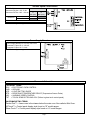
1
FREESTANDING ELECTRIC RANGE
PRODUCT SERVICE MANUAL
EI30EF55G ,
* ,, CEI30EF5G
*
*
*
MODELS - EW30EF65G
CEW30EF6G
Wave-Touch™
IQ Touch™
EW30EF65
Publication # 5995521555
August 2008
EI30EF565
PN / 316439223
TABLE OF CONTENTS
SAFE SERVICING PRACTICES............................... 3
SERVICE TIPS - DEVELOP GOOD
WORK HABITS.......................................................... 4
SERVICE TOOLS AND EQUIPMENT....................... 4
RANGE TECHNICAL DATA.................................5-14
Maximum Allowable
Surface Temperatures........................................... 5
RTD Temperature / Resistance Chart................... 5
Electric Range Component
Resistance Chart................................................... 5
Oven Relay Board Circuit Analysis Matrix
(ES 610/615)......................................................... 6
EOC Signal Voltage Test Matrix............................ 6
Variable Speed Control Board............................... 7
Power Supply Board............................................. 7
Terms and Abbreviations....................................... 7
ELECTRONIC OVEN CONTROL
FAILURE/FAULT CODES (ES630)....................... 8
ELECTRONIC SURFACE ELEMENT CONTROL
(ESEC 30) TROUBLESHOOTING GUIDE
Wave Touch Models........................................ 9
IQ Touch Models........................................... 10
Wiring Diagram - Electric Wave Touch Models
with Lower Oven................................................. 11
Schematic Diagram - Electric Wave Touch Models
with Lower Oven................................................. 12
Wiring Diagram - Electric IQ Touch Models
with Warming Drawer.......................................... 13
Schematic Diagram - Electric IQ Touch Models
with Warming Drawer.......................................... 14
PRODUCT OVERVIEW........................................... 15
Touch Sensor Technology
(TST) Control SYSTEM...................................... 16
Troubleshooting The TST Panel.......................... 16
Diagnostic Service Mode.................................... 17
eLECTRONIC SURFACE ELEMENT
CONTROL SYSTEM (esec 30).............................. 18
ERROR CODES - Wave Touch Models............. 18
ERROR CODES - IQ Touch Models.................. 19
eLECTRONIC oven CONTROL (es 630) ............ 20
EOC Troubleshooting and Testing....................... 21
Power Supply Boards.................................... 23
VARIABLE SPEED CONTROL............................... 24
Variable Fan Speed............................................. 24
LUXURY™ Lighting............................................. 25
RACK SENSING SWITCH....................................... 26
MEAT PROBE FEATURE........................................ 28
Theory Of Operation........................................... 28
Component Parts................................................ 28
Troubleshooting................................................... 28
Component access and replacement
Cooktop & Elements....................................... 29
Surface Element Replacement........................... 30
OVEN DOOR............................................................ 31
Door Removal..................................................... 31
Door Disassembly............................................... 32
UPPER OVEN Components............................... 35
Bake Element...................................................... 35
Broil Element....................................................... 36
Convection Fan Blade and
Element Replacement......................................... 37
Rack Sensing Switch Replacement.................... 37
Halogen Oven Lights........................................... 38
Luxury Glide Oven Rack
Removal & Maintenance..................................... 39
Rack Sensor Assembly
Removal & Maintenance..................................... 40
Lower Oven Component Service................ 41
Replacing Lower Oven Element.......................... 41
Replacing Drawer Glide Rails............................. 42
Replacing Drawer Seal....................................... 42
Lower Oven Chassis........................................... 43
Warmer DRAWER
Theory of Operation....................................... 44
Warmer DRAWER
Component Service......................................... 44
Removing and Replacing
Warmer Drawer .................................................. 44
Replacing Warmer Drawer
Element & Thermo Disc...................................... 45
MODEL APPLICATION LIST
The information contained in this manual can be
applied to the models listed below:
EW30EF65GW EI30EF55GW
EW30EF65GB EI30EF55GB
EW30EF65GS EI30EF55GS
CEW30EF6GW CEI30EF5GW
CEW30EF6GB CEI30EF5GB
CEW30EF6GS CEI30EF5GS
NOTE:
The information contained in this manual is subject
to change as product development continues after
the date this manual was created.
Page 09/0408
SAFE SERVICING PRACTICES
- ALL APPLIANCES To avoid personal injury and/or property damage, it is important that Safe Servicing Practices be
observed. The following are some limited examples of safe practices:
1. DO NOT attempt a product repair if you have any doubts as to your ability to
complete it in a safe and satisfactory manner.
2. Before servicing or moving an appliance:
• Remove the power cord from the electrical outlet, trip the circuit breaker to the
OFF position, or remove the fuse.
• Turn off the gas supply.
• Turn off the water supply.
3. Never interfere with the proper operation of any safety device.
4. USE ONLY REPLACEMENT PARTS CATALOGED FOR THIS APPLIANCE.
SUBSTITUTIONS MAY DEFEAT COMPLIANCE WITH SAFETY
STANDARDS SET FOR HOME APPLIANCES.
5. GROUNDING: The standard color coding for safety ground wires is GREEN, or
GREEN with YELLOW STRIPES. Ground leads are not to be used as current
carrying conductors. It is EXTREMELY important that the service technician
reestablish all safety grounds prior to completion of service. Failure to do so will
create a hazard.
6. Prior to returning the product to service, ensure that:
• All electrical connections are correct and secure
• All electrical leads are properly dressed and secured away from sharp edges,
high-temperature components, and moving parts
• All non-insulated electrical terminals, connectors, heaters, etc. are adequately
spaced away from all metal parts and panels
• All safety grounds (both internal and external) are correctly and securely
connected
• All panels are properly and securely reassembled
• All gas connections are secure and have been leak tested
ATTENTION!!!
This service manual is intended for use by persons having electrical and mechanical
training and a level of knowledge of these subjects generally considered acceptable in
the appliance repair trade. The manufacturer cannot be responsible, nor assume any
liability, for injury or damage of any kind arising from the use of this manual.
Page SERVICE TIPS - DEVELOP GOOD WORK HABITS
Consistently following a standard routine when servicing appliances will insure that you do not
waste time searching for a complex solution to a simple problem. One of the most common mistakes
made by service technicians is failing to verify the incoming power supply to the appliance.
Many times electronic controls and other components are replaced unnecessarily because
the incoming power supply was not verified. When testing the electrical supply the test should be
performed at the terminal block where the power cord or house wiring attaches to the appliance.
Verify that there are 240 volts between L1 & L2 and that there is 120 volts from L1 to Neutral and
also from L2 to Neutral. You should also check the power supply while the appliance is operating
or “under load”. The power supply may check good with the product sitting idle but fail when certain
components are turned on. This can be caused by a weak connection in the customer’s house wiring,
or a faulty circuit breaker or fuse.
Another common mistake is failure to verify all component part wire harness connections. It is
essential that all component connections be checked visually and with the appropriate circuit tester.
Many times components are assumed to be faulty because they do not operate or there is an error
code displayed by the electronic control system. Often the failure is caused by a loose or miswired
connection which can cause the same error code as a defective component part. Newly installed
appliances may have loose connections resulting from shipping and handling conditions or improper
installation. Check the wiring connections before you order replacement parts.
When the repair has been completed the product should be thoroughly tested to verify that the
service performed corrected the problem and that all of the other features and functions of the product
are in proper working order. The extra time taken to do this will create consumer confidence in your
efficiency and professionalism as well as possibly saving an expensive callback.
SERVICE TOOLS AND EQUIPMENT
In addition to standard hand tools such as wrenches, screwdrivers, pliers, etc; the following
instruments are considered to be essential equipment for technicians servicing Electrolux cooking
products. Proper testing and diagnostic procedures are not possible without these tools.
• Volt/ohmmeter - Must be capable of voltage measurement from 0 to 500 volts AC and
resistance measurements from 0 to 2 meg-ohms. This usually requires a meter that utilizes a 9 volt battery. Either digital or analog meters are acceptable however most technicians find analog meters easier to use. Appropriate test leads and tips are required to test certain
electronic components and connections.
• Clamp on amp meter - Should be capable of measuring from 0 to 60 amps.
• Temperature Meter - Should be high quality with thermocouple or electronic
“K-type” test probe. Capable of temperature readings up to 1000 degrees Fahrenheit.
Additional instruments that a technician will need to have access to at various times include the
following:
• Combustible gas leak detection meter.
• U tube manometer or equivalent testing device for measuring LP and Natural gas line
pressure on gas ranges. Measurements must be in IWC (inches water column)
• Carbon Monoxide (CO) detection meter capable of measuring from 0-1000 PPM.
• Microwave Leak Detection Meter
NOTE: Electrolux Does Not Supply Tools Or Test Instruments.
Page RANGETECHNICAL
TECHNICAL DATA
RANGE
DATA
Maximum Allowable Surface Temperatures
All gas and electric ranges must comply with U.L and A.N.S.I. surface temperature limits outlined in the following chart.
Note that the testing temperature is different for electric ranges produced after 08/26/2003.
SURFACE TEMPERATURE LIMITS
MATERIAL TYPE / FINISH
PAINTED
PORCELAIN
Side Panel
152° F
160° F
Oven Door
152° F
160° F
Warmer Drawer
Front Panel
152° F
160° F
—
Knobs & Handles
—
—
—
*167° F
**182° F
Skirt
—
—
—
*182° F
1. Product must be undamaged, correctly assembled and have the correct oven temperature.
GLASS
PLASTIC†
METAL
—
—
—
172° F
182° F
—
—
—
LOCATION
2. All skin temperatures are based on a room temperature of 77° F (25° C)
and an oven set temperature as specified below:
For ELECTRIC ranges built prior to 08/26/2003 - 400° F
For ELECTRIC ranges built after 08/26/2003 - 475° F
For GAS ranges built prior to 01/01/2004 - 400° F
For GAS ranges built after 01/01/2004 - 475° F
3. Oven must be cycling at designated test temperature for one hour
before test is conducted.
4. Pyrometers, (temperature testers), must be of high quality and properly
adjusted.
Cooktop
Lower Console
Oven Vent Area
5. An increase or decrease of 1° F in the room ambient temperature, will
allow a 1° F increase or decrease in the maximum allowable surface
temperature of the range.
131° F
**152° F
*152° F
NO TEMPERATURE LIMITS APPLY TO THIS AREA
†
Includes plastic with metal plating not more than 0.005” thick and metal with a plastic covering not
less than 0.005” thick.
* Self-Clean Gas Range at Clean Temperature
** Self-Clean Electric Range at Clean Temperature
RTD Temperature / Resistance Chart
The chart seen here can be used to test the resistance of
the oven temperature sensor probe. For accuracy in testing
use a high quality thermometer or temperature meter to
determine actual oven temperature before reading the
resistance of the probe.
RTD SCALE
Temperature (°F)
Resistance (ohms)
32 ± 1.9
1000 ± 4.0
75 ± 2.5
1091 ± 5.3
250 ± 4.4
1453 ± 8.9
350 ± 5.4
1654 ± 10.8
450 ± 6.9
1852 ± 13.5
550 ± 8.2
2047 ± 15.8
650 ± 9.6
2237 ± 18.5
900 ± 13.6
2697 ± 24.4
Probe circuit to case ground
Open circuit / Infinite Resistance
Electric Range Component Resistance Chart
NOTE: Resistance measurements are approximate. Variations due to temperature changes
and other factors are normal.
Component
Voltage
Rating
Wattage
APPROXIMATE
Resistance Ω (ohms)
Bake ELEMENT
208 / 242
3000
16 Ω
BROIL ELEMENT
208 / 242
4000
14 Ω
Warmer Drawer Element
108 / 132
700
20.5 Ω
Warmer Drawer Element
108 / 132
450
32 Ω
Mini oven element
108 / 132
1000
14 Ω
Convection Element
108 / 132
350
40 Ω
Convection element
108 / 132
200
72 Ω
Convection Fan Motor
Windings
108 / 132
35 Ω
Lock Motor Windings
108 / 132
2000 Ω
OVEN TEMPERATURE SENSOR
PROBE (AT ROOM TEMPERATURE)
Page 1100 Ω *
*(refer to rtd chart)
RANGE TECHNICAL DATA
ES 610/615 Oven Relay Board Circuit Analysis Matrix
Relay Contacts
P4 (R)
to
P2 (O)
P6 (BK)
to
P10 (Y)
P6 (BK)
to
P8 (BL)
P6 (BK)
to
P12 (Y/BK)
J4/3 (BK)
to
J4/5 (V)
J4/3 (BK)
to
J4/6 (BR)
Component
L2 Out
Relay
Bake
Element
Broil
Element
Lower Oven
Element
Convection
Element
Door Lock
Motor
X
X
X
X
Bake / Time Bake
Convection Bake/Roast
O
P
E
R
A
T
I
O
N
P
X
X
Broil
Dehydrate
X
X
X
X
X
X
X
X
Bread Proof
Slow Cook
Keep Warm (Upper Oven)
X
X
Keep Warm (Lower Oven)
Bake (Lower Oven) *
Door Lock Motor
Locking/Unlocking
Clean
X = Contact Closed
*Some Models
X
X
X
P = Contact closed during Pre-Heat only
EOC Signal Voltage Test Matrix
Test for 3.3 VDC (+/- .5 volts) between GND on EOC circuit board and the indicated connector pin when the specified
function is activated.
FREESTANDING ELECTRIC and DUAL FUEL MODELS
FUNCTION / RELAY
EOC CONNECTOR / PIN#
RELAY BOARD CONNECTOR / PIN #
Lower Oven or Warmer Drawer / K3
P9
/ Pin 7
J5 / Pin 7
L2 Out
/ K2
P11 / Pin 4
J7 / Pin4
Broil
/ K4
P11 / Pin 1
J7 / Pin 1
Bake
/ K6
P11 / Pin 2
J7 / Pin 2
Convection Element / K10
P11 / Pin 5
J7 / Pin 5
Lock Motor / K12
P11 / Pin 6
J7 / Pin 6
Page VSC Test Points.
Connector P6 pins 1 & 6 - 5 vdc
Connector P2 Pins 3 & 5 - 120 vac
OPERATION
Variable Speed Control Board
RELAY CONTACTS
P2/5 (BK)
to
P2/1 (Tan)
Oven Lamps
P2/5 (BK)
to
P2/7 (Pink)
X
Convection Fan Mtr.
X
X = Contact Closed
NOTE: All voltages are approximate.
Power Supply Board
Power Supply Board (PS1 or PS2) Test Points
Connector P1 pins 1 & 4 - 120 vac
Connector P2 pins 1 & 5 - 8 vdc
NOTE: All voltages are approximate.
Terms and Abbreviations
TECHNICAL TERMS
EOC = ELECTRONIC OVEN CONTROL
GND = GROUND
LED = LIGHT EMITTING DIODE
RTD = RESISTANCE TEMPERATURE DEVICE (Temperature Sensor Probe)
VSC = VARIABLE SPEED CONTROL
TST = TOUCH SENSOR TECHNOLOGY (Refers to glass touch control panel)
SALES/MARKETING TERMS
Perfect Pair™ = Lower oven in the drawer below the main oven. Also called a Mini Oven.
IQ Touch™ = Control panel display style found on “B” model ranges.
Wave-Touch™ = Control panel display style found on “A” model ranges.
Page RANGE TECHNICAL DATA
ELECTRONIC OVEN CONTROL
FAILURE/FAULT CODES (ES630)
For each Fault code there is a listing of the likely failure condition or cause, as well as suggested
corrective actions to be taken. Perform the steps one at a time in the order listed below to correct the
specific failure condition.
Note: Fault codes are not a foolproof system. Never assume that a part has failed based on a displayed fault
code. An example would be if the EOC is displaying F30 (open sensor), the failure could be caused by a loose
connection or faulty wire harness between the EOC and sensor or the sensor could simply be unplugged.
FAULT
CODE
LIKELY FAILURE
CONDITION/CAUSE
SUGGESTED CORRECTIVE ACTION
F10
Runaway Temperature.
Oven heats when no cook
cycle is programmed.
1. Check RTD Sensor Probe using the RTD scale found in the tech sheet. Replace if defective.
2. If oven is overheating disconnect power from the range and unplug connector P1 from power supply
board 1. Reapply power to the range. If oven continues to heat when the power is reapplied, replace the
oven relay board.
3. Replace the EOC
NOTE: Severe overheating may require the entire oven to be replaced should damage be extensive.
F11
Shorted Keypad
1. Reset power supply to range to see if failure code will clear.
2. Check/reseat ribbon harness connections between TST panel and EOC.
3. Replace the TST panel
4. Replace the EOC
F13
Internal software error in
EOC
Disconnect power, wait 30 seconds and reapply power. If fault returns upon power-up, replace EOC.
F14
TST Display tail missing or
not connected
1. Check/reseat ribbon harness connections between TST panel and EOC.
2. Replace the TST panel
3. Replace the EOC
F15
Signal loss between oven
relay board and EOC
1. Test the harness and connections from EOC connector P16 to oven relay board J2.
2. Replace the oven relay board
3. Replace the EOC
F20
Communication failure
between EOC and ESEC
1. Test wiring harness and connections between EOC connector P2 and ESEC 30 UIB P9
2. Test wiring harness and connections between ESEC 30 UIB and ESEC 20 relay board
3. Test wiring harness and connections between PS board 2 (P2) and ESEC 30 UIB connector P7
4. Test for approximately 8 volts DC output from PS board 2 at ESEC 30 UIB connector P7, pins 1 & 5.
If output voltage is incorrect test incoming power supply to PS board 2 at harness connector P1 pins
1 & 4. If incoming power is correct (120 VAC) replace PS board 2.
If output voltage is correct replace ESEC 30 UIB
5. Replace EOC
F23
F25
Communication failure
between VSC board and
EOC
1. Check harness and connections between VSC board and EOC.
2. Test for approximately 5 volts DC to VSC board at P6 connector pins 1 & 6.
If voltage is correct replace VSC board. If voltage is incorrect replace EOC.
F30
Open probe connection.
F31
Shorted Probe connection
1. (F30 or F31) Check resistance at room temperature & compare to RTD Sensor resistance chart. If
resistance does not match the RTD chart replace RTD Sensor Probe. Check Sensor wiring harness between
EOC & Sensor Probe connector.
2. (F30 or F31) Check resistance at room temperature, if less than 500 ohms, replace RTD Sensor Probe.
Check for shorted Sensor Probe harness between EOC & Probe connector.
F90
Door lock motor latch
failure
Electric
Models
Only
If lock motor runs:
1. Test continuity of wiring between EOC and lock switch on lock motor assy. Repair if needed.
2. Advance motor until cam depresses the plunger on lock motor switch. Test continuity of switch contacts.
If switch is open replace lock motor assy.
3. If motor runs and switch contacts and wiring harness test good, replace the EOC
If lock motor does not run:
1. Test continuity of lock motor windings. Replace lock motor assy if windings are open.
2. Test lock motor operation by using a test cord to apply voltage. If motor does not operate replace lock
motor assy.
3. If motor runs with test cord check continuity of wire harness to lock motor terminals. If harness is good
replace the EOC.
Page RANGE TECHNICAL DATA
ELECTRONIC SURFACE ELEMENT CONTROL (ESEC 30) TROUBLESHOOTING GUIDE
- Wave Touch Models For each Fault code there is a listing of the likely failure condition or cause, as well as suggested
corrective actions to be taken. Perform the steps one at a time in the order listed below to correct the
specific failure condition.
SYMPTOM
Control Beeping
No Error Codes
Displayed
LIKELY FAILURE
CONDITION/CAUSE
SUGGESTED CORRECTIVE ACTION
ESEC key display ribbon
cable is disconnected or
defective
1. Check/reseat ribbon connection J3 connection on the ESEC 30 UIB.
2. Replace ESEC 30 UIB.
3. Replace TST panel.
ESEC key display ribbon
cable is disconnected or
defective
1. Check/reseat ribbon connection J2 connection on the ESEC30 UIB.
2. Replace ESEC 30 UIB.
3. Replace TST panel.
Shorted Keypad
1. Reset power supply to range to see if failure code will clear.
2. Check/reseat ribbon harness and connectors between the TST panel and ESEC 30 UIB.
3. Replace the TST panel
4. Replace the ESEC 30 UIB
“ E 14 “
In Displays
ESEC key read ribbon
cable is disconnected or
defective
1. Check/reseat ribbon connection J4 connection on the ESEC 30 UIB.
2. Replace ESEC 30 UIB.
3. Replace TST panel.
“ E 15 “
In Displays
Signal loss between ESEC
30 UIB and ESEC relay
board.
1. Check/reseat harness and connections between connector P6 of ESEC30 UIB to connector J2 of
ESEC relay board. Repair or replace harness as needed.
2. If connection and harness are good. then replace ESEC relay board.
3. If error remains ESEC30 UIB.
4. If the previous steps do not resolve the failure replace the TST panel.
Surface element and its
associated hot surface
limiter mis-wired
1. Correct wiring of that element and its hot surface limiter.
“HE” displayed
when surface is
cold
1. Hot surface limiter
contacts closed.
2. Defective Relay Board.
3. Defective ESEC 30 UIB
1. Disconnect power and check continuity of hot surface limiter contacts. (See Note A)
2. If hot surface limiter contacts are open replace ESEC relay board.
3. Replace ESEC 30 UIB
Surface
Element hot,
but “HE”
is not displayed
1. Loose connection
between surface element
and Relay Board J4
2. Miswired element
harness.
3. Open limiter contacts.
4. Failed harness or
connector from UIB to
Relay Board
5. Defective Relay Board.
6 Defective ESEC 30 UIB
1. Check the wire harness connector and seat properly to Relay Board J4 connector.
2. Check surface harness for correct wiring from each element’s hot surface limiter correct wiring or replace harness if necessary.
3. Turn on all elements to Hi. Wait 3 minutes to ensure all surfaces are hot. Check
continuity of limiter switch circuit for each element. (See Note A)
4. Check the wire harness and connectors from ESEC 30 UIB P5 to Relay Board
Connector J5. Replace harness if defective.
5. Replace Relay Board
6. Replace ESEC 30 UIB
Element does not
heat when turned
on at TST panel.
1. Miswiring or faulty connection from element to
Relay Board
2. Faulty connection from
ESEC 30 UIB to ESEC
Relay Board
3. Open Element
4. Defective Relay Board
5. Defective UIB
1. Check wiring harness and connections from element to Relay Board.
2. Check harness and connections from UIB connector P10 to Relay Board J3.
3. Check continuity of surface element heating circuit.
4. Replace ESEC Relay Board.
5. Replace ESEC 30 UIB
“E“
In Displays
“E 11”
In Displays
“HE”
displayed and no
power to Element
Note A: Limiter contacts can be tested through the
harness on Relay Board connector J4
Page RANGE TECHNICAL DATA
ELECTRONIC SURFACE ELEMENT CONTROL (ESEC 30) TROUBLESHOOTING GUIDE
- IQ Touch Models For each Fault code there is a listing of the likely failure condition or cause, as well as suggested
corrective actions to be taken. Perform the steps one at a time in the order listed below to correct the
specific failure condition.
SYMPTOM
LIKELY FAILURE CONDITION/
CAUSE
SUGGESTED CORRECTIVE ACTION
Control Beeping &
Center Burner Only
LED’s Flashing
ESEC key display ribbon cable is
disconnected or defective
1. Check/reseat ribbon connection J3 connection on the ESEC 30 UIB.
2. Replace ESEC 30 UIB.
3. Replace TST panel.
Control Beeping &
Left Side Burners
Only LED’s
Flashing
ESEC key display ribbon cable is
disconnected or defective
1. Check/reseat ribbon connection J2 connection on the ESEC30 UIB.
2. Replace ESEC 30 UIB.
3. Replace TST panel.
Control Beeping &
All Burners LED’s
Flashing
E11 Failure Mode - Shorted Keypad
Turn off power to range for 30 seconds then reapply power.
Does error return within 5 seconds ?
YES: Go to Solution A
NO: Does error return after 30 seconds?
YES: Go to Solution B NO: Test operation. If error does not return then the
condition was corrected by power reset.
or
E14 Failure Mode - ESEC key
read ribbon cable is unplugged or
defective
or
E15 Failure Mode - Internal ESEC
error or Signal loss between ESEC
30 UIB and ESEC relay board.
Solution A - E14 Failure Mode key read ribbon cable is disconnected or defective
1. Check/reseat ribbon connection J4 connection on the ESEC 30 UIB.
2. Replace ESEC 30 UIB.
3. Replace TST panel.
E15 Failure Mode ESEC error or signal loss between ESEC 30 UIB and relay board.
1. Check harness and connections between connector P6 of ESEC30 UIB to
connector J2 of ESEC relay board. Repair or replace harness as needed.
2. If connection and harness are good. then replace ESEC relay board.
3. If error remains replace ESEC30 UIB.
4. If the previous steps do not resolve the failure replace the TST panel.
Solution B - E11 Failure Mode Shorted Keypad
1. Reset power supply to range to see if failure code will clear.
2. Check/reseat ribbon harness and connectors between the TST panel and ESEC
30 UIB.
3. Replace the TST panel
4. Replace the ESEC 30 UIB
“hot surface”
displayed and no
power to Element
Surface element and its associated
hot surface limiter mis-wired
1. Correct wiring of that element and its hot surface limiter.
“hot surface”
displayed when
surface is cold
1. Hot surface limiter contacts closed.
2. Defective Relay Board.
3. Defective ESEC 30 UIB
1. Disconnect power and check continuity of hot surface limiter contacts. (See Note A)
2. If hot surface limiter contacts are open replace ESEC relay board.
3. Replace ESEC 30 UIB
Surface
Element hot,
but “hot surface”
is not displayed
1. Loose connection between surface
element and Relay Board J4
2. Miswired element harness.
3. Open limiter contacts.
4. Failed harness or connector from
UIB to Relay Board
5. Defective Relay Board.
6 Defective ESEC 30 UIB
1. Check the wire harness connector and seat properly to Relay Board J4 connector.
2. Check surface harness for correct wiring from each element’s hot surface limiter correct wiring or replace harness if necessary.
3. Turn on all elements to Hi. Wait 3 minutes to ensure all surfaces are hot. Check
continuity of limiter switch circuit for each element. (See Note A)
4. Check the wire harness and connectors from ESEC 30 UIB P5 to Relay Board
Connector J5. Replace harness if defective.
5. Replace Relay Board
6. Replace ESEC 30 UIB
Element does not
heat when turned
on at TST panel.
1. Miswiring or faulty connection from
element to Relay Board
2. Faulty connection from ESEC 30
UIB to ESEC Relay Board
3. Open Element
4. Defective Relay Board
5. Defective UIB
1. Check wiring harness and connections from element to Relay Board.
2. Check harness and connections from UIB connector P10 to Relay Board J3.
3. Check continuity of surface element heating circuit.
4. Replace ESEC Relay Board.
5. Replace ESEC 30 UIB
Note A: Limiter contacts can be tested through the
harness on Relay Board connector J4
Page 10
Wiring Diagram - Electric Wave Touch Models with Lower Oven
Page 11
Schematic Diagram - Electric WaveTouch Models with Lower Oven
Page 12
Wiring Diagram - Electric IQ Touch Models with Warming Drawer
Page 13
Schematic Diagram - Electric IQ Touch Models with Warming Drawer
Page 14
PRODUCT OVERVIEW
Electrolux branded freestanding electric ranges are currently available in two distinct model series.
The Wave Touch series and IQ Touch series.
Both designs feature a smooth ceramic glass cooktop with electronic surface element controls, self
cleaning main oven with hidden bake element, convection and normal bake modes in the main oven,
variable speed convection fan motor, Luxury Glide oven racks, Dual halogen oven lights, and meat
probe.
The Wave Touch models also feature a Perfect Pair™ lower oven capable of baking at temperatures
up to 450 degrees in addition to functioning as a warming drawer.
The IQ Touch models features a lower warming drawer only. The appearance of the Touch Sensor
control panel of the IQ Touch series is also very different from the Wave Touch series as will be seen
later in this manual.
The oven and warmer drawer functions are controlled by the ES630 Electronic Oven Control. Surface
elements are controlled by the ESEC 30 electronic surface element control system.
The oven door hinges are designed to allow the door to stand open in virtually any position without
springing closed.
Current finish options available are White , Black and Stainless Steel. Both ranges operate on 220
volt 60 hz AC power supply.
IQ Touch™
Wave-Touch™
EW30EF65
Page 15
EI30EF565
Touch Sensor Technology (TST) Control SYSTEM
The TST system utilizes a touch sensitive glass panel (photo A) to allow the user to control the upper
and lower ovens, warmer drawer and cooktop surface elements including the cooktop Warmer Zone
element. The TST panel is connected to the electronic oven control (EOC) and the electronic surface
element control (ESEC) system UIB (user interface board) via ribbon connectors. It is similar in
function to a membrane switch.
The TST control panel generates an electromagnetic field around each touch pad. When this field is
interrupted by touching the glass, the control panel communicates the selection information to the
EOC or ESEC system . The EOC or ESEC system then responds by signaling the oven relay board
or surface element control board to close the appropriate relays to perform the selected operation or
function.
NOTE: The TST system touch glass is a non serviceable part and must be replaced as a complete
assembly if found to be defective. The replacement glass panel will come attached to the frame and
will include ribbon connectors. (Photo B)
Photo A
Frame
Touch Glass
Photo B
Troubleshooting The TST Panel
The TST control panel has ribbon connectors that link it to the EOC and ESEC 30 UIB. (Photo C).
If these connectors fail or become loose the TST control panel will not operate and under some
conditions will generate a fault code in the EOC or ESEC display window.
If the TST control malfunctions or fails to operate inspect and re-seat the ribbon connectors. If a
failure/fault code is present follow the diagnostic procedure for that code.
If no fault code appears but the EOC system does not respond when the TST panel is programmed
then the cause can be the EOC or the TST panel. Replace the EOC first. If the problem remains
replace the TST panel assembly.
Photo C
ESEC 30 UIB
EOC
If the ESEC does not respond when the TST
panel is programmed then the cause can be
the ESEC UIB or the TST panel. Replace the
UIB first. If the problem remains replace the
TST panel assembly.
If only a single key is non responsive then the
TST panel is the most likely cause of failure.
Ribbon Connectors
Page 16
Diagnostic Service Mode
When an error or failure occurs in the Electronic Oven Control (EOC) system, or the Electronic Surface
Element Control (ESEC) system, the control panel will usually produce an audible beep accompanied by a
special display to indicate that there is a failure condition. The manner in which ESEC failures are displayed
will vary greatly between the Wave Touch models and the IQ touch models due to the different styles of
control panels. In order for a service technician to be able to more easily determine which failure condition has
occurred a special Diagnostic Service Mode has been built in to the control panel software.
To enter the service mode the range must be in the “IDLE” condition meaning that all elements and functions
are turned off. Press and hold the TIMER keypad for the upper oven and the Upper Oven selector keypad for 3
seconds. Always press the TIMER keypad first immediately followed by the Upper Oven selector keypad.
After three seconds the control panel will enter the service mode and will display the most recent error or
failure codes for the upper and lower ovens as well as the ESEC system.
The control will exit the Diagnostic Service Mode after one minute or it can be ended by pressing the CANCEL
keypad. The service mode can be restarted if necessary by repeating the steps outlined above. While the
control is in the Diagnostic Service Mode the error codes can be cleared from memory by pressing the Upper
Oven Timer keypad. Once they are cleared they can not be recalled.
Error Displayed
for Upper Oven
Control
Error Displayed
for Lower Oven
Control
Press and Hold for three seconds
to start Service Mode
Error Displayed
for ESEC System
The photo above shows an IQ Touch control panel that has been programmed into the Diagnostic Service
Mode. The upper oven control is displaying an F11 error code (Stuck Keypad), The lower oven control is
displaying no error code, and the ESEC error code E 14 is displayed in the upper oven timer window. Once
it has been determined which failure condition is present follow the troubleshooting steps outlined in the tech
sheet and this service manual to correct that specific condition.
.
NOTE: The Diagnostic Service Mode works exactly the same for both IQ Touch and Wave Touch models.
Page 17
eLECTRONIC SURFACE ELEMENT CONTROL SYSTEM (esec 30)
The ESEC 30 Electronic Surface Element Control System operates the radiant surface elements and
warming zone element. The ESEC 30 UIB receives the operator selection from the TST panel and
signals the ESEC 20 Surface Unit Control Board (relay board) which then closes the appropriate relay
to turn on the desired element.
If a failure occurs in the ESEC system there are several error codes that may be displayed to guide
the service technician in diagnosing the failure.
It is important to note that the error codes are displayed are differently between the “A” models with
Wave-Touch™” display and the “B” model with “ IQ Touch™” display. Although the display method is
different the potential failure conditions and possible cause are the same.
ERROR CODES Wave Touch Models
When a failure occurs in the ESEC system the control
will beep and usually display an error code. These error
codes will appear in two front element displays. The left
side will display the letter E and the right side will display
the error code number. (Fig 1). In some cases the control
may beep and display only the letter “ E “ in the left
display or there may be no display in either window.
Fig 1
The troubleshooting guide below provides a listing of the likely failure condition or cause, as well as
suggested corrective actions to be taken. Perform the steps one at a time in the order listed below to
correct the specific failure condition.
ELECTRONIC SURFACE ELEMENT CONTROL (ESEC 30) TROUBLESHOOTING GUIDE
- Wave Touch ModelsSYMPTOM
Control Beeping
No Error Codes
Displayed
LIKELY FAILURE
CONDITION/CAUSE
SUGGESTED CORRECTIVE ACTION
ESEC key display ribbon
cable is disconnected or
defective
1. Check/reseat ribbon connection J3 connection on the ESEC 30 UIB.
2. Replace ESEC 30 UIB.
3. Replace TST panel.
ESEC key display ribbon
cable is disconnected or
defective
1. Check/reseat ribbon connection J2 connection on the ESEC30 UIB.
2. Replace ESEC 30 UIB.
3. Replace TST panel.
Shorted Keypad
1. Reset power supply to range to see if failure code will clear.
2 Check/reseat ribbon harness and connectors between the TST panel and ESEC 30 UIB.
3. Replace the TST panel
4. Replace the ESEC 30 UIB
“ E 14 “
In Displays
ESEC key read ribbon
cable is disconnected or
defective
1. Check/reseat ribbon connection J4 connection on the ESEC 30 UIB.
2. Replace ESEC 30 UIB.
3. Replace TST panel.
“ E 15 “
In Displays
Signal loss between ESEC
30 UIB and ESEC relay
board.
1. Check/reseat harness and connections between connector P6 of ESEC30 UIB to connector J2 of
ESEC relay board. Repair or replace harness as needed.
2. If connection and harness are good, then replace ESEC relay board.
3. If error remains ESEC30 UIB.
4. If the previous steps do not resolve the failure replace the TST panel.
“E“
In Displays
“E 11”
In Displays
Page 18
ERROR CODES - IQ Touch Models
When a failure occurs in the ESEC system the control will beep and half
of the power level indicator segments for the surface elements will flash in
various combinations to indicate which error has occurred. (Fig. 1)
The troubleshooting guide provides a listing of the likely failure condition or
cause, as well as suggested corrective actions to be taken.
Perform the steps one at a time in the order listed below to correct the
specific failure condition. In some cases you can also use the diagnostic
service mode described on page 17 to determine which ESEC error
condition is present
Fig 1
ELECTRONIC SURFACE ELEMENT CONTROL (ESEC 30) TROUBLESHOOTING GUIDE
- IQ Touch ModelsSYMPTOM
LIKELY FAILURE CONDITION/
CAUSE
SUGGESTED CORRECTIVE ACTION
Control Beeping &
Center Burner Only
LED’s Flashing
ESEC key display ribbon cable is
disconnected or defective
1. Check/reseat ribbon connection J3 connection on the ESEC 30 UIB.
2. Replace ESEC 30 UIB.
3. Replace TST panel.
Control Beeping &
Left Side Burners
Only LED’s
Flashing
ESEC key display ribbon cable is
disconnected or defective
1. Check/reseat ribbon connection J2 connection on the ESEC30 UIB.
2. Replace ESEC 30 UIB.
3. Replace TST panel.
Control Beeping &
All Burners LED’s
Flashing
E11 Failure Mode - Shorted Keypad
Turn off power to range for 30 seconds then reapply power.
Does error return within 5 seconds ?
YES: Go to Solution A
NO: Does error return after 30 seconds?
NO: Test operation. If error does not return then the
YES: Go to Solution B condition was corrected by power reset.
or
E14 Failure Mode - ESEC key
read ribbon cable is unplugged or
defective
or
E15 Failure Mode - Internal ESEC
error or Signal loss between ESEC
30 UIB and ESEC relay board.
Solution A - E14 Failure Mode key read ribbon cable is disconnected or defective
1. Check/reseat ribbon connection J4 connection on the ESEC 30 UIB.
2. Replace ESEC 30 UIB.
3. Replace TST panel.
E15 Failure Mode ESEC error or signal loss between ESEC 30 UIB and relay board.
1. Check harness and connections between connector P6 of ESEC30 UIB to
connector J2 of ESEC relay board. Repair or replace harness as needed.
2.. If connection and harness are good, then replace ESEC relay board.
3. If error remains replace ESEC30 UIB.
4. If the previous steps do not resolve the failure replace the TST panel.
Solution B - E11 Failure Mode Shorted Keypad
1. Reset power supply to range to see if failure code will clear.
2. Check/reseat ribbon harness and connectors between the TST panel and ESEC
30 UIB.
3. Replace the TST panel
4. Replace the ESEC 30 UIB
Page 19
ELECTRONIC oven CONTROL (ES630)
The Electrolux branded ranges covered in this manual feature the ES630 Electronic Oven Control
(EOC) . This control system is comprised of the Electronic Oven Control Board, Oven Relay Board,
and Power Supply Board. The ES630 EOC interfaces with the TST (Touch Sensor Technology) panel
to allow the consumer to select the desired function and options.
There are currently two different versions of the TST control panels sometimes referred to as “A” and
“B” versions. Other terms used to refer to the different control styles are: “Wave-Touch™” for the A
model and “ IQ Touch™” for the B model.
The most obvious difference is the appearance of
the control panels when they are in an idle state.
The Wave-Touch™ display panel has a “sleep
mode” that turns off the illuminated control icons
on the touch panel whenever the range is idle for 2
minutes (Diag A). During this sleep mode only the
time of day will be illuminated in the control panel.
Diag.A
To wake the control simply touch the glass surface.
The touch control keypads will illuminate to allow the
user to program the desired function (Diag B).
Diag. B
The IQ Touch™ display panel has permanent
graphics imprinted in the glass panel and will remain
visible at all times (Diag C).
Diag. C
In current models the Wave-Touch control is always used on ranges that feature the “Perfect Pair™
lower oven”, also referred to as a Mini Oven.
Models that have the IQ Touch control feature a warmer drawer instead of a mini oven.
Page 20
ELECTRONIC oven CONTROL (ES630)
EOC Troubleshooting and Testing
The Electronic Oven Control system found in the Electrolux freestanding electric ranges uses a
separate oven relay board to power the individual components such as the bake and broil elements,
lock motor, warmer drawer or lower oven element, etc. This is different from some other styles of
electronic oven controls where the EOC and control relays are integrated in to a single component.
The servicer must follow the troubleshooting and diagnostic information found in this manual and in
the product tech sheet to accurately diagnose any failures and avoid unnecessary parts replacement.
Photo A shows the locations of the EOC Board, Oven Relay Board, ESEC 30 UIB and Power supply
boards as seen from the rear of the range with the rear panel removed. The ribbon connectors to the
TST panel can be seen at the bottom of the EOC board.
ESEC 30 UIB
Photo A
EOC Board
Power Supply Boards
Oven Relay Board
Page 21
ELECTRONIC oven CONTROL (ES630)
If a component part that is controlled by the EOC fails to operate the cause could be due to a defect
in the EOC, Oven Relay Board, wiring connections , or the non functioning component. Component
parts such as elements, fan motors, lock motors, etc. can be tested with a simple continuity check
using an ohm meter. Verify the continuity of the component and the wiring circuit between the
component to the relay board first. Also verify continuity of the wiring harness and connectors
between the EOC and Oven Relay Board.
If the component and wiring connections are good test the output signal voltage from the EOC to the
Relay board for the particular relay that turns on that component part. When testing the output signal
set your volt meter to read DC voltage. The output signal will be approximately 3.3 volts DCV.
Using the EOC SIGNAL VOLTAGE TEST MATRIX it is possible to determine if the EOC is properly
signaling the relay board to turn on a particular component. If the proper signal is detected but the
relay does not close then the relay board is defective and must be replaced. If the proper signal is not
detected then the EOC is defective and must be replaced.
RELAY BOARD CONNECTORS
EOC Signal Voltage Test Matrix (ES630)
J7
Test for 3.3 VDC (+/- .5 volts) between GND on EOC circuit board and the
indicated connector pin when the specified function is activated.
J5
FREESTANDING ELECTRIC MODELS, and DUAL FUEL MODELS
FUNCTION
EOC Test Points
Connector/Pin#
Relay Board Test Points
Connector/Pin #
Lower Oven or Warmer Drawer
P9/Pin 7 → to GND
J5/Pin 7
→
to GND
L2 Out Relay
P11/Pin 4 → to GND J7/Pin 4
→
to GND
Broil Relay
P11/Pin 1 → to GND
J7/Pin 1
→
to GND
Bake Relay
P11/ Pin 2 → to GND J7/Pin 2
→
to GND
Convection Element Relay
P11/Pin 5 → to GND J7/Pin 5
→
to GND
Lock Motor Relay
P11/Pin 6 → to GND J7/Pin 6
→
to GND
When testing the signal voltage from the EOC the negative (-) lead of the test meter must connect
the GND circuit on the EOC circuit board. The easiest access point to the GND circuit is located just
above the left corner of the P11 connector. (Photo A). Either of the GND access points can be used.
Photo B demonstrates testing the Bake Relay signal voltage by measuring the voltage output
between connector J7 pin #2 (red wire) and the GND circuit on the EOC circuit board on a gas range.
GND (-) CIRCUIT ACCESS POINTS
BAKE RELAY SIGNAL VOLTAGE TEST
Photo A
Photo B
Page 22
Power Supply Boards
The EOC and ESEC system are powered by separate power supply boards that are mounted on the
rear of the range chassis just below the EOC as seen in photo A.
The two Power Supply Boards are identical however one board is designated as PS 1 and the other
is PS 2 on the wiring diagram. PS 2 provides the power supply to the EOC while PS 1 powers the
ESEC system. Wire harness connections and colors are identical on both boards and it does not
matter which board is connected to the EOC or ESEC system however the length of the wiring
harness will only allow both harnesses to be connected in one orientation.
Incoming voltage to the boards should be approximately 120 VAC at P1. Output voltage should be
approximately 8 VDC at P2.
Always test the incoming and outgoing voltage at the power supply boards when troubleshooting
EOC or ESEC control failures.
Photo A
EOC Board
Power Supply Board
Power Supply Board (PS1 or PS2) Test Points
Connector P1 pins 1 & 4 - 120 vac
Connector P2 pins 1 & 5 - 8 vdc
NOTE: All voltages are approximate.
PS 2
PS 1
Power Supply Boards
If there is a failure in the PS 1 (ESEC) power supply board or wiring the ESEC system display will not
illuminate and the surface elements can not operate. Additionally there will likely be an F20 failure
code displayed on the EOC display after several seconds.
If there is a failure in the PS 2 (EOC) power supply board or wiring the EOC display will not illuminate
and the oven components and other devices can not operate. The ESEC system may still allow the
surface elements to operate even though the EOC does not .
Page 23
VARIABLE SPEED CONTROL
The Variable Speed Control (VSC) board operates the Convection Fan as well as the Oven
LUXURY™ lighting. In the event that either of these features do not operate properly the VSC board
should be examined as a possible source of failure. When testing for convection fan operation it
should be noted that on gas ranges there is a six minute delay from the start of the convection
cooking cycle until the fan motor will run.
Variable Fan Speed
To achieve optimum cooking results during convection cooking the fan motor speed can be varied.
The EOC will signal the VSC board to speed up or slow down the fan as needed. This speed change
takes place automatically with no action required by the consumer.
The VSC Board is located on the rear of the range
just below the power supply boards, as seen
in photo A. The board varies the voltage to the
convection fan motor as directed by the EOC to
alter the motor speed. The speed control signal and
the power supply to operate the VSC board come
from the EOC through a wiring harness connected
between P2 on the EOC and P1 on the VSC board.
This harness must be intact and properly connected
for the VSC board to operate. If the harness is
defective or not properly connected the EOC will
display a fault code F23.
When testing the VSC board the power supply from
the EOC to the board can be verified by measuring
the voltage between pins 1 & 6 (the two outside pins)
on connector P6 of the VSC board. This connector is
not wired in field applications and the pins are easily
accessed to test voltage while the other harness
connectors are in place and power is applied to
the range. Test for approximately 5 volts DC (+/.5 volt) on these two pins. If the EOC appears to
operate normally but the voltage to the VSC board is
incorrect or if there is no voltage present inspect and
test the wire harness and connectors between the
EOC and VSC board. If the harness is good then the
EOC is defective and should be replaced.
Photo A
VSC Board
P2
Photo B
P6
Pin 1
Pin 6
P1
If the convection fan motor fails to run test for voltage to the convection fan motor. If no voltage is
present then the failure is either in the VSC board, EOC , or the wiring in between. If there is proper
voltage to the fan motor but it does not run then either the motor windings are open or the motor is
stuck. Test the continuity of the motor windings with an ohm meter. There should be approximately
15 ohms of resistance in the convection fan motor windings. If the windings test good inspect the fan
blade and motor shaft to see if the motor will turn. Adjust the fan blade to eliminate binding or replace
the motor assembly if the motor shaft is seized.
Page 24
LUXURY™ Lighting
When the oven door is opened or the LIGHT keypad
on the touch control panel is pressed the interior
oven halogen lights (photo A) come on and brighten
gradually. When turned off they dim gradually
until they are completely off. This feature is also
sometimes referred to as “Ramp Up lighting”.
Photo A
The incremental changing of the oven lights is
controlled by the VSC board. A triac on the board
gradually increases the voltage to the lights over a
2 - 3 second time span until the lights are on at full
power.
If none of the halogen oven lights operate, plug
in the range and open the oven door. Test for
approximately 120 volts AC at pins 1 & 3 of the P2
wire harness connector (brown & white wires) on the
VSC board (photo B).
Always use special care when making live voltage
tests.
If the voltage is correct then the failure is caused by
defective bulbs, sockets or wiring connections.
If the voltage is incorrect the problem could be
caused by a defective door switch, VSC board, or
EOC.
Test the contacts of the oven door switch by
disconnecting the P10 connector on the EOC and
checking for continuity between the grey and pink
wires in the wire harness.
Page 25
P2
Photo B
P6
Pin 1
Pin 3
P1
RACK SENSING SWITCH
In order to prevent damage to the extendable
telescoping interior oven racks, the EOC will not
perform a self clean cycle until the racks are removed.
A rack sensing switch mounted in the rear of the oven
liner signals to the EOC that the racks have been
removed. (Photo A)
When the oven racks are installed the rear edge of the
rack pushes against a pivoting rod on the rack sensor
assembly causing a cam on the rod to depress the
sensor switch. When the switch is depressed the switch
contacts are open. As long as the switch contacts are
open the EOC will assume that the racks are installed
in the oven.
When the racks have been removed the cam of the
sensor rod releases the pressure on the rack sensing
switch allowing the switch contacts to close.
When the EOC detects that the rack sensing switch
contacts are closed it will allow the self cleaning cycle
to operate.
Mtg. screw
Rack Sensing
Switch
Rack Sensor
Assembly
Photo A
If the customer starts a self cleaning cycle without
removing the racks a message on the EOC will
illuminate instructing them to remove the racks.
(Photo B).
If the racks have been properly removed but the EOC
displays the REMOVE RACKS message then the failure
could be caused by defective switch contacts, wiring
harness connections, stuck sensor rod assembly or
defective EOC.
Examine the sensor assembly rod to be sure it can
move freely. Also inspect the metal plunger cover on
the switch to make sure it has not stuck. The sensor
rod assembly can be removed for cleaning and
lubricating if necessary.
If the sensor switch becomes stiff or hard to depress
the metal cap may need lubrication on the underside at
the contact point of the switch plunger.
Use only an approved , water based graphite lubricant
on the sensor assembly and switch. Part number is
5304468694 and is available through your authorized
parts distributor.
Page 26
Mtg. screw
Photo B
RACK SENSING SWITCH
To test the rack sense switch contacts remove the rear
wire cover on the range and access the wire harness
connector P10 on the EOC. (Photo A)
Unplug the harness and test for continuity between the
blue & grey wires in the harness. When the racks are
removed there should be less than 1 ohm of resistance
if the switch contacts are closed.
If the switch contacts are closed but the EOC displays
the “REMOVE RACKS” message then the EOC is
defective.
If the switch contacts are open then test the switch
through the harness plug on the switch itself. Unplug
the harness connector (Photo B) and test for continuity
between he brown wires of the harness.
If the switch contacts are open replace the switch. If the
switch contacts are closed then the harness from the
switch to the EOC is defective.
Photo A
EOC P10 Connector
Photo B
Rack Switch Harness Connector
Page 27
MEAT PROBE FEATURE
Theory Of Operation
Some models feature a meat probe that is used to monitor the internal temperature of the food during
cooking. The meat probe is a RTD (Resistance Temperature Device) similar to the oven temperature
sensor found in ranges with electronic oven controls. As the temperature of the meat probe increases
the resistance decreases. The E O C monitors this resistance whenever the probe is inserted into the
receptacle and uses this information to determine when the food has reached the target temperature.
Component Parts
The components of the meat probe
feature are: Probe assembly (Fig 1 )
and the receptacle assembly which
includes the wire harness (Fig 2 ).
Fig 2
Fig 1
Troubleshooting
Possible failures of the meat probe feature are:
• Loose wire or harness connection. • Defective meat probe.
• Defective receptacle and wiring harness.
• Defective Electronic Oven Control.
To troubleshoot the meat probe feature first test the probe itself
by using an ohm meter to measure resistance. Place one of the
meter leads on the very tip of the probe plug and the other lead
on the adjacent short segment as indicated in the photo.
The resistance will vary depending on the actual temperature of
the probe. At a room temperature of 77 degrees the resistance
will measure approximately 46,000 ohms.
Probe Resistance
Test Points
To test the accuracy of the probe place the metal wand end into a container of water that has a
temperature of 120 degrees Fahrenheit and measure the resistance. At 120 degrees the resistance
should be between 17,860 ohms and 19,740 ohms. If the resistance is incorrect replace the probe.
If the probe resistance is correct plug the probe into the receptacle inside the oven and disconnect
the probe harness connector from the E O C connection P 18.
Measure the resistance between the two
Probe Harness
wires in the harness plug. If the resistance is
Connector P 18
approximately equal to the resistance of the
probe then the harness and receptacle circuit
are good.
If the resistance is significantly higher or lower than that of the probe then the receptacle and wiring
harness should be replaced. The receptacle and wiring harness are replaced as an assembly.
If the probe, receptacle and harness are good but the probe feature does not work the failure is in the
E O C and it must be replaced.
Page 28
Component access and replacement
Cooktop & Elements
The procedure for servicing the smooth glass cooktop
and surface elements is similar to other Electrolux
manufactured ranges. The front of the cooktop can
be lifted by removing the screws that secure it to the
range chassis. (Photo A)
Note: The exact quantity and position of the screws
can vary between models.
Once these screws have been removed slide the
entire cooktop assembly forward approximately three
inches to disengage the hinge tabs found on each
side of the cooktop from the slot in the backguard
assembly. (Photo B).
Raise the front of the top up and use a wooden
or plastic dowel to support the top while service is
performed. (Photo C)
With the cooktop in the raised position the surface
heating elements, warmer zone element and their
wiring connections are accessible.
Page 29
Photo A
Remove Screws
Photo B
Tab Slot
Hinge Tab
Photo C
Surface Element Replacement
1. Before removing the element be sure to note
the locations of the element mounting clips in the
support channel slot. The replacement element must
be installed in the same position.
2. Carefully remove the wires from the element.
Take note of the terminal identification on the
element terminal block for each wire connection.
4. Remove the mounting screw that secures the
3. Before the element can
element support channel to the cooktop.
be removed from the support
channel the locking tab on the
mounting clip must be closed
by squeezing shut with a pair
of pliers. After the repair is
complete the tab can be
reopened by using an awl or
similar instrument.
5. Carefully pull the support channel away from
the cooktop far enough to disengage the element
mounting clips from the channel. Slide the element
out from between the support channel and the
cooktop. Reinstall or replace the element by
reversing steps 1-5.
Clip
The element mounting clips must be removed
from the original element and mounted to the
replacement. The screw holes on the element
body are numbered to identify the clip mounting
locations.
Page 30
OVEN DOOR
Door Removal
All components and parts of the Oven Door assembly can be serviced or replaced. The door is not
available as a complete assembly.
Photo A
Photo B
To service the door begin by removing the door
from the range. Open the door fully and pull both
hinge locks down until they stop. (Photo A & B)
Gently close the door until it stops against the hinge
locks at approximately a 45 degree angle. (Photo C)
Make sure you have a firm grasp on the door and
continue closing the door to disengage the hinges
from the receivers. (Photo D)
When the door is about 4 inches away from being
completely closed it can be lifted off the range.
(Photo E)
To reinstall the door reverse the previous steps. Use
your knee to stabilize and help guide the hinge arms
into the receiver slots in the frame. Once the door is
secure in the frame open it fully and close the hinge
locks back in to their normal position.
Page 31
Photo C
Photo D
Photo E
Door Disassembly
To service or replace the door components remove
the door as previously described and place the door
on a protected work surface with the handle side
down.
Photo A
REMOVE
SCREWS
Begin disassembly by removing the two screws
at the top of the porcelain door liner (Photo A),
Carefully turn the door over so that the handle side
is facing up. Remove the four screws located along
the bottom edge of the door. (Photo B )
Lift off the outer glass panel with door handle and
top trim cap attached.
Photo B
REMOVE
SCREWS
To remove and replace the door handle or top trim
cap remove the two screws on the back side of the
trim cap that secure the cap and door handle to the
door panel outer glass . (Photo C)
REMOVE SCREWS
Photo C
The outer door panel is replaced as an assembly
which includes the metal frame with outer glass, foil
tape and name badge already attached.
If the foil tape is not already attached install it
around the window opening as seen in Photo D.
Photo D
FOIL TAPE
Page 32
Door Disassembly
With the outer door panel remove the door filler trims
can be removed by taking out the two screws found
in each trim. (Photo A)
REMOVE SCREWS
Remove the air wash glass and mounting brackets by
removing the four screws that secure the brackets to
the porcelain door liner. (Photo B)
NOTE: The mounting brackets may be attached to the top
or the sides of the airwash glass depending on model.
Photo A
Photo B
REMOVE SCREWS
To remove the door hinge remove two hinge
mounting screws from the outside of the porcelain
door liner and pull the hinge out from the back.
(Photo C)
Photo C
REMOVE SCREWS
The hinges used in different models have the same
general appearance so to help identify the hinge a
color stripe is painted onto the spring. (Photo D)
When replacing the hinge make sure that the
spring color matches the color stated in the parts
description from the part list.
Page 33
Photo D
7316508700 Hinge Assembly, door, blue
Door Disassembly
Remove the wool shield by taking out the remaining
four screws securing the shield to the door liner.
(Photo A).
Photo A
REMOVE SCREWS
When reinstalling the wool shield be sure that
the bottom edge of the shield is nested under the
upturned edge of the porcelain door liner. Photo (B)
WOOL SHIELD
Photo B
DOOR LINER
Photo C
Carefully lift out the four pieces of insulation
surrounding the window cutout. When reinstalling the
insulation take care to tuck the insulation under the
screw brackets on the porcelain liner. (Photo C)
FOUR
INSULATION PIECES
Lift out the two inner door glass panes and their
spacer leaving only the porcelain door liner with door
gasket still attached.
The gasket is secured to the liner by spring clips
that can be pulled out from the opposite side. Make
sure to re-insert the loose ends of the gasket into
the holes at the bottom of the door liner before
reinstalling the inner door glass panes or insulation.
(Photo D)
Page 34
Photo C
DOOR GASKET
ENDS
UPPER OVEN Components
Bake Element
To remove and replace the bake element remove the
oven door and all interior oven racks. Remove the
rack sensor assembly by taking out the two screws
in the top mounting bracket and lifting the bracket
and sensor assembly rod out of the lower bracket.
(Photo A)
Remove the two screws that secure the convection
fan cover to the rear of the oven wall and remove the
cover. Remove the two screws at the rear corners of
the oven bottom panel. (Photo B)
Using your finger tips press down on the front edge
of the oven bottom to cause it to lift upward in the
rear of the oven cavity. (Photo C).
Lift the rear of the oven bottom upward and slide
it toward the rear oven wall to disengage the front
edge from the chassis. Remove the oven bottom.
(Photo D)
Page 35
Photo A
Mtg. screws
Photo B
Photo C
Photo D
Bake Element
The bake element is eight pass, 240 volts, 3000
watts. It is secured to the oven liner by the four
screws indicated by the red arrows in Photo A.
Photo A
Before removing the bake element disconnect the
element wires which can be accessed by removing
the lower rear shield on the back of the range.
(Photo B)
Photo B
Bake Element
Wires
Broil Element
The broil element is eight pass, 240 volts, 4000
watts. It is secured to the oven liner by the six
screws indicated by the red arrows in Photo B.
Photo C
Before removing the broil element disconnect the
element wires which can be accessed by removing
the lower rear shield on the back of the range.
Photo D
Broil Element
Wires
Page 36
Convection Fan Blade and Element Replacement
The Convection Fan Blade and Element are concealed by the fan cover. Remove the cover as
described on page 35.
The Blade can be removed by using a 13mm
The convection element is a single pass, 120
socket wrench to remove the blade retaining
volts, 350 watts. It is secured to the oven liner
nut. The nut has left hand threads so to remove
by the two screws indicated by the red arrows in
the nut turn the wrench in a clockwise direction.
Photo B.
(Photo A)
Photo B
Photo A
Turn Nut Clockwise
To Remove
Before removing the convection element
disconnect the element wires which can be
accessed by removing the lower rear shield on the
back of the range. (Photo C)
Photo C
Rack Sensing Switch Replacement
The rack sensing switch is installed into a cutout in the
oven liner rear wall. (Photo D)
To replace the switch first turn off the power to the
range and remove the lower back cover panel.
Unplug the harness connector (Photo E) and tie a 36
inch length of strong string or cord to the end of the
connector that is attached to the switch. Secure the
other end of the string so that it can not pull all the way
through.
From inside the oven remove the rack sensor assembly
by taking out the two screws at the top and bottom of
the assembly. (Page 26 - Photo A).
Depress the tabs on the switch (Photo D) to release it
from the cutout and carefully pull the switch with the
attached wire harness inside the oven cavity.
Attach the string to the new switch harness and
carefully pull the harness back through the oven liner
and insulation .
Page 37
Photo D
Rack Switch
Harness Connector
Photo E
Halogen Oven Lights
Each light assembly houses a replaceable 40 watt
bulb behind the clear lens.
To remove the lens use a thin bladed screwdriver or
putty knife to gently pry the lens out. Take care not to
damage the finish of the oven wall. (Photo A)
With the lens removed the bulb can be accessed.
Remove the bulb by pulling it out of the porcelain
base in the direction shown by the arrow in photo B.
Use only the correct replacement bulb.
Please note: do not allow your fingers to touch the
new bulb when replacing. This will shorten the life
of the new bulb. Use a paper towel to cover the new
bulbwhen installing.
If the socket or harness are defective the complete
assembly with attached harness, bulb and lens must
be replaced. The light assembly is installed from the
inside of the oven cavity.
When removing the old assembly it is recommended
to tie a string to the end of the harness plug as the
assembly is being removed. This string can then
be used to fish the wire harness of the replacement
assembly through the oven cavity liner and inner
shield.
Always orient the assembly with the wire harness
towards the center of the oven. (Photo C)
Page 38
Photo A
Photo B
Pull Bulb To
Remove
Toward Oven
Center
Photo C
Luxury Glide Oven Rack Removal & Maintenance
Using your thumbs push both plungers in at the
same time to unlock the rack. (Photo B).
Pull the rack assembly forward to remove it
from the oven.
To remove and replace the Luxury Glide oven
racks open the oven door completely. Locate
the spring loaded plunger below the rack
bearing channel on each side of the rack.
(Photo A).
Photo B
Photo A
The Luxury Glide Oven Racks have no serviceable parts and should be replaced as a complete
assembly if defective. The ball bearing glide assemblies on the oven racks should be lubricated
annually or more often as needed. Use only the approved water based graphite lubricant.
NEVER use grease or oil of any kind to lubricate the racks or bearings. Approved lubricant is
available through your authorized Electrolux parts supplier under part number 5304468694. This
lubricant should also be used on the rack switch sensor rod assembly
To lubricate the bearings remove the racks as
Lubricate Here
described in the owners manual. Place the rack on
a protected work surface and slide the rack to the
fully extended position to expose the ball bearing
assembly inside the track. Using the dispenser tip
of the lubricant bottle place a few drops of lubricant
on the top and bottom bearing carriers in the areas
indicated by the arrows in photo C. The lubricant
Photo C
will be spread to all of the ball bearings as the rack
is operated. Use the lubricant sparingly, a few drops
is all that is necessary.
Repeat this process for each bearing assembly. There are two bearing assemblies on each side
of the rack, one on the inside as seen in the photo and one on the outside. Also lubricate the rack
release plunger mechanism at all friction points as needed.
Page 39
Rack Sensor Assembly Removal & Maintenance
The pivot points of the oven rack sensor
assembly should be lubricated annually or more
often as needed.
Use only the approved water based graphite
lubricant available through authorized Electrolux
parts dealers. NEVER use grease or oil of any
kind to lubricate the rack sensor assembly.
To lubricate the assembly remove all oven racks
from the inside of the oven. Use the dispenser
tip of the lubricant bottle to place a few drops of
lubricant at the pivot points of the rack sensor
assembly bar. (Photo A)
Use the lubricant sparingly, a few drops is all that
is necessary.
Lubricate
Here
Photo A
To remove the rack sensor assembly begin by taking
out the two screws in the top mounting bracket and
lifting the bracket and sensor assembly rod out of
the lower bracket. (Photo B). The lower bracket can
now be removed if necessary.
Page 40
Photo B
Mtg. screws
Lower Oven Component Service
Replacing Lower Oven Element
Remove Drawer
Fig. 1
1. Before drawer removal, be sure to turn OFF
the lower oven and let the drawer area cool
completely.
2. Open the drawer to the fully open position.
Using a phillips-head screwdriver remove the two
drawer screws from the insides of the front oven
drawer compartment (See Fig. 1).
3. With one hand hold the drawer front in place.
Use your other hand to pull the glide away from
the oven (See Fig. 2) until the glide hook
disengages (See Fig. 3 & Fig. 4).
4. Repeat from step 3 above for the other side of
the drawer.
5. With both glide hooks disengaged, carefully
lift the drawer up and away from the oven. Push
both drawer glides into lower oven cavity.
From the rear of the range remove the six screws
that secure the lower rear shield. ( Fig. 5 )
Note that the center screw in the upper edge of
the panel is concealed behind the power cord. It
may be necessary to remove the cord to access
this screw.
Fig. 2
Fig. 3
Fig. 4
Glide Hook Disengaged
Glide Hook Engaged
This screw concealed
by power cord
Fig. 5
After the shield is removed the wire terminals to
the lower oven element and light can be accessed.
( Fig. 6 )
Element Terminals
With the drawer removed and the element wire
harness disconnected remove the eight screws
that secure the element to the base and remove
the element by pulling forward. ( Fig. 7 )
To remove the mounting screws a short / stubby
¼” nut driver or # 1 square drive screwdriver is
required.
Fig. 6
Use caution when working in this area.
There are sharp edges on the element
brackets and other areas. Protective clothing and / or gloves are recommended.
Fig. 7
Page 41
Replacing Drawer Glide Rails
The lower oven drawer glide rails (Fig. 8) clip into
the side wall of the lower oven cavity and are secured by one screw in each rail.
Fig. 8
The mounting screw is accessed through a hole in
the glide rail outer track. (Fig. 9) .
Fig. 9
Remove
Screw
Once the mounting screw is removed extend the outer track of the glide rail until it stops. Pull forward
firmly until the hooks on the back of the rail disengage from the slots in the oven cavity side wall.
( Fig. 11 & 12 )
Fig. 11
Fig. 12
Slots
Pull Forward
Glide Rail Hooks
Replacing Drawer Seal
The rubber drawer seal is secured to the drawer liner by metal
spring clips that are integral to the seal. To remove the seal grasp
securely at the clip and pull away from the liner. Replace by
positioning the point of the clip into the hole and pressing in until
the clip locks into place.
Page 42
Spring Clip
Lower Oven Chassis
The lower oven chassis can be removed as an
entire assembly. Begin by disconnecting the wire
harness connections to the element and cavity
light.
Remove the drawer per instructions on page 41.
Screw Access
Using a ¼” nut driver with magnetic screw holder
remove the two screws securing the lower oven
chassis to the range chassis. These screws are
accessed through the holes in the lower oven
cavity liner just below the drawer glide rail. (Photo
A).
Photo A
The lower oven chassis can now be pulled forward
and removed from the range. (Photo B).
With the lower oven chassis removed the
insulation and chassis panels can be serviced.
NOTE: The lower oven chassis is not available as a
complete replacement assembly.
Lower Oven
Chassis
Assembly
Page 43
Photo B
Warmer DRAWER Theory of Operation
Warmer drawer operation is controlled by the EOC and Oven Relay board. When the warmer drawer
is first activated a thermal disk mounted in the drawer cavity is used to detect when the warmer
drawer is cold and a call for heat is needed.
If the thermal disk is initially closed, the EOC assumes that the warmer drawer is cold. In this case the
Warmer Drawer relay activates and the heating element provides continuous heat (100% time ON)
until the thermal disk opens.
After the thermal disk opens the control starts cycling the warmer drawer relay based on timing data
that is programmed into the EOC. The cycle timings correspond to the warmer drawer settings and
are typically as follows:
WD Settings
150°F
160°F
170°F (default)
180°F
190°F
Relay Timing
10 sec ON
50 sec OFF
15 sec ON
45 sec OFF
20 sec ON
40 sec OFF
25 sec ON
35 sec OFF
30 sec ON
30 sec OFF
The thermal disk status is monitored during all the time while the Warmer Drawer is active. If the
status changes to “closed”, the relay activates again and the heating element provides continuous
heat until the thermal disk opens.
Warmer DRAWER Component Service
Removing and Replacing Warmer Drawer
To Remove the Warming Drawer:
1. Turn power off before removing the Warmer Drawer.
2. Open the drawer to the fully opened position (Photo C)
3. Remove the retaining screw in the right glide release
lever.
4. Pull up on the left glide lever and push down on the
right glide lever.
5. Pull the drawer away from the range.
To Replace the Warming Drawer:
1. Pull the bearing glides to the front of the chassis
glide (See Photo D).
2. Align the glide on each side of the drawer with the glide
slots on the range.
3. Push the drawer into the range until levers “click”
(approximately 2”). Pull the drawer open again to seat
bearing glides into position. If you do not hear the levers
“click” or the bearing glides do not feel seated remove the
drawer and repeat steps 1-3. This will minimize possible
damage to the bearing glides.
4. Reinstall the retaining screw in the right glide lever
Page 44
Photo C
Lever
Screw
Bearing Glide
Photo D
Replacing Warmer Drawer Element & Thermo Disc
The warmer drawer element and thermo disc are
mounted to a metal base pan which must be removed in
order to replace the element.
Remove the lower wire shield from rear of the range.
Unplug the warmer drawer harness connector and push
the connector through the slot in the back panel so that it
can be removed with the element and base assembly.
Remove the screws that secure the warmer drawer base
and the warmer drawer side shields to the main back
panel. (Photo A)
Harness Connector Plug
Side Shield Screws
Photo A
Remove the ¼” hex screws that secure the drawer
guide rail and element base pan on each side of the
drawer opening. (Photo B)
Remove the drawer guide rail and drawer shield together
by pulling straight forward.
Element Base Pan Screw
Guide Rail Screw
Drawer Guide Rail
Drawer Side Shield
Once both of the drawer guide rails and side shields have
been removed the base pan and element assembly can
be pulled forward to remove from the range. (Photo C)
Photo B
With the element and base pan assembly removed
the element and thermo disc are accessible for
servicing. (Photo D)
To remove the element from the pan remove the
screws and clips that secure it to the pan. Also remove
the screw that secures the thermo disc mounting
bracket.
Photo D
Pull base pan forward to
remove
→→
When reinstalling the thermo disc mounting
bracket always insure that the element terminal
shield is installed and properly positioned.
Base Pan Screw
Photo C
Mounting Screws and Clips
Thermo Disc Mounting Bracket
Warmer Drawer Element and
Base Pan Assy
Terminal Shield
Page 45
Page 46
NOTES
Page 47