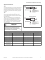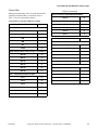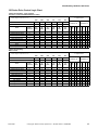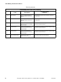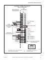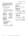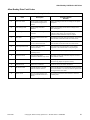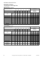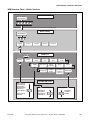
1
Supplement
Washer/Extractor
AC Adjustable Frequency
Drive Information
For Allen-Bradley Model Numbers:
160
1305
1336
PowerFlex 40
PowerFlex 400
U072M
U072M
PHM1396C
TMB1396C
U074M
U074M
FA
U
RE LT
AD
Y
U071M
U073M
U073M
U071M
Part No. F232120R7
April 2014
Supplement
Table of
Contents
General Information...........................................................................
Nameplate Location..............................................................................
General Inspection ................................................................................
Storage ..................................................................................................
3
4
5
5
PowerFlex 40 and 400 Drive Control Logic .....................................
Installation/Wiring................................................................................
Input Power Conditioning................................................................
Electrical Interference ......................................................................
Terminal Block Access ....................................................................
Power Terminal Block Description .................................................
Control Terminal Blocks Description and Control Logic................
AC Drive Diagnostics/Parameter Viewing...........................................
PowerFlex Integrated Keypad..........................................................
Fault Display and Troubleshooting Information ..................................
Allen-Bradley Drive Fault Codes ....................................................
Troubleshooting Suggestions...........................................................
6
6
6
7
8
9
10
28
28
32
33
35
Allen-Bradley 160-Series AC Drives.................................................
Installation/Wiring................................................................................
Input Power Conditioning................................................................
Electrical Interference ......................................................................
Terminal Block Access ....................................................................
Power Terminal Block Description .................................................
Control Terminal Blocks Description and Control Logic................
160 Series Drive Control Logic Chart .............................................
AC Drive Diagnostics/Parameter Viewing...........................................
160 Program Keypad Module (PKM or Parameter Unit) ................
CopyCat Keypad ..............................................................................
Fault Display and Troubleshooting Information ..................................
Fault Code Identification .................................................................
Allen-Bradley Drive Fault Codes ....................................................
Troubleshooting Suggestions...........................................................
36
36
36
37
39
40
41
42
51
51
54
58
58
59
61
Allen-Bradley 1305-Series AC Drives...............................................
Installation/Wiring................................................................................
Input Power Conditioning................................................................
Electrical Interference ......................................................................
Terminal Block Access ....................................................................
Power Terminal Block Description .................................................
Control Terminal Blocks Description and Control Logic................
AC Drive Diagnostics/Parameter Viewing...........................................
Human Interface Module (HIM or Parameter Unit) ........................
HIM Structure Chart – Series A 3.00, Series B 1.01 or
Later Versions ....................................................................................
HIM Structure Chart – Earlier Versions...............................................
Fault Display and Troubleshooting Information ..................................
Fault Code Identification .................................................................
Allen-Bradley Drive Fault Codes ....................................................
Troubleshooting Suggestions...........................................................
62
62
62
63
64
65
65
73
73
75
76
80
80
81
83
© Copyright 2014, Alliance Laundry Systems LLC
All rights reserved. No part of the contents of this book may be reproduced or transmitted in any form or by any
means without the expressed written consent of the publisher.
F232120R7
© Copyright, Alliance Laundry Systems LLC – DO NOT COPY or TRANSMIT
1
Supplement
Allen-Bradley 1336-Series AC Drives............................................... 84
Installation/Wiring................................................................................ 84
Input Power Conditioning................................................................ 84
Electrical Interference ...................................................................... 85
Terminal Block Access .................................................................... 86
Power Terminal Block Description ................................................. 87
Control Terminal Blocks Description and Control Logic................ 88
AC Drive Diagnostics/Parameter Viewing........................................... 98
Human Interface Module (HIM or Parameter Unit) ........................ 98
HIM Structure Chart – Series A 3.00, Series B 1.01 or
Later Versions ................................................................................ 100
HIM Structure Chart – Earlier Versions .......................................... 101
Fault Display and Troubleshooting Information .................................. 105
Fault Code Identification ...................................................................... 105
Allen-Bradley Drive Fault Codes .................................................... 107
Troubleshooting Suggestions........................................................... 109
2
© Copyright, Alliance Laundry Systems LLC – DO NOT COPY or TRANSMIT
F232120R7
General Information
General Information
• This drive contains ESD (Electrostatic
Discharge) sensitive parts and assemblies. Static
control precautions are required when installing,
testing, or servicing this assembly. Component
damage may result if ESD control procedures are
not followed.
• An incorrectly applied or installed drive can
result in component damage or a reduction in
product life. Wiring or application errors, such as
incorrect or inadequate AC supply or excessive
ambient temperatures, may result in malfunction
of the system.
CAUTION
Only personnel familiar with the drive and
associated machinery should plan or
implement the installation, start-up, and
subsequent maintenance of the system.
Failure to comply may result in personal
injury and/or equipment damage.
W659
• This drive contains power storage devices that
retain their charge for a time after the removal of
main power. Extreme caution should be used
when working in and around the drive. It is
recommended that main disconnect power to the
drive remain off for three minutes prior to
approaching connections.
Warnings specific to a particular subject will appear in
the manual with the discussion of that subject.
F232120R7
© Copyright, Alliance Laundry Systems LLC – DO NOT COPY or TRANSMIT
3
General Information
Nameplate Location
Pertinent drive information used in obtaining
information on drive operation or replacement is
located on the nameplate shown in Figures 1
through 4.
Nameplate Located on
Exterior of Enclosure
1305 NAMEPLATE LOCATION
U072ME3A
U072ME3A
FA
U
RE LT
AD
Y
Figure 2
Nameplate Located on
Exterior of Enclosure
160 NAMEPLATE LOCATION
U146ME3A
U146ME3A
Figure 1
Nameplate Located
on Bottom Portion of
Chassis Behind Cover
Nameplate Located
on Mounting Plate of
Main Control Board
FRAMES B-G
FRAMES A1, A2, A3, A4
U147ME3A
1336 PLUS NAMEPLATE LOCATION
U147ME3A
Figure 3
Nameplate Located on
Exterior of Enclosure.
TMB1396C
POWERFLEX NAMEPLATE LOCATION
PHM1396C
Figure 4
4
© Copyright, Alliance Laundry Systems LLC – DO NOT COPY or TRANSMIT
F232120R7
General Information
General Inspection
Storage
Upon delivery, verify the item’s nameplate catalog
number against the purchase order.
The drive should remain in its shipping container prior
to installation. If the equipment is not to be used for a
period of time, it must be stored according to the
following instructions in order to maintain warranty
coverage:
Before the installation and start-up of the drive, a
general inspection of the mechanical integrity (i.e.,
loose parts, wires, connections, etc.) should be made.
• Store in a clean, dry location.
• Store within an ambient temperature range of -40
to 70 degrees C.
• Store within a relative humidity range of 0 to 95
percent.
• Do not store equipment where it could be
exposed to a corrosive atmosphere.
• Do not store equipment in a construction area.
F232120R7
© Copyright, Alliance Laundry Systems LLC – DO NOT COPY or TRANSMIT
5
PowerFlex 40 and 400 Drive Control Logic
PowerFlex 40 and 400 Drive Control Logic
Installation/Wiring
Input Power Conditioning
The drive is suitable for direct connection to input
power within the rated voltage of the drive. Listed in
Table 1 are certain input power conditions which may
cause component damage or reduction in product life.
If any of the conditions exist, as described in Table 1,
install one of the devices listed under the heading
Corrective Action on the line side of the drive.
CAUTION
An incorrectly installed system can result in
component damage or reduction in product
life. The most common causes are:
1. Wiring AC line to drive output or control
terminals.
IMPORTANT: Only one device per branch circuit
is required. It should be mounted closest to the
branch and sized to handle the total current of the
branch circuit.
2. EXTERNAL voltage application to control
terminals.
3. Incorrect or inadequate AC supply.
Contact factory for assistance with
application or wiring.
W660
Input Power Condition
Corrective Action
Low Line impedance (less than 1% line reactance)
Greater than 120 kVA supply transformer
Line has power factor correction capacitors
Line has frequent power interruptions
•
•
•
Install Line Reactor
or Isolation Transformer
or Bus Inductor – 5.5 & 11kW (7.5 & 15 HP) drives
only
•
•
Install Line Reactor
or Isolation Transformer
•
•
Remove MOV jumper to ground.
or Install Isolation Transformer with grounded
secondary
if necessary
•
Install Line Reactor
Line has intermittent noise spikes in excess of 6000V
(lightning)
Phase to ground voltage exceeds 125% of normal line to line
voltage
Ungrounded distribution system
240V open delta configuration (stinger leg) (1)
(1)
For drives applied on an open delta with a middle phase grounded neutral system, the phase opposite the phase that is tapped in the
middle to the neutral or earth is referred to as the “stinger leg,” “high leg,” “red leg,” etc. This leg should be identified throughout the
system with red or orange tape on the wire at each connection point. The stinger leg should be connected to the center Phase B on the
reactor.
Table 1
6
© Copyright, Alliance Laundry Systems LLC – DO NOT COPY or TRANSMIT
F232120R7
PowerFlex 40 and 400 Drive Control Logic
Electrical Interference
SINGLE PHASE MACHINES
EMI
L1 ALLEN-BRADLEY
RFI
L2
LINE
INPUT
POWER
Careful attention must be given to the arrangement of
power and ground connections to the drive to avoid
interference with nearby sensitive equipment. Be sure
to replace all ground connections to their appropriate
locations.
FILTER
LOAD
1 2
2 3
3
PROVEN EARTH GROUND
WASHING
MACHINE
GROUNDING
TERMINAL
RFI
Drives can be installed with an RFI filter, which
controls high-frequency conducted emissions into the
main supply lines.
TO AC DRIVE UNIT Ð
GREEN-YELLOW WIRE MUST CONNECT TO
AC DRIVE GROUND TERMINAL.
BLACK WIRES WILL CONNECT TO AC DRIVE
INPUT TERMINALS "R", "S" & "T".
BLACK WIRES ARE NOT LABELED AND THEIR
RESPECTIVE TERMINATION IN AC DRIVE IS
NOT OF IMPORTANCE.
THREE PHASE MACHINES
Where it is essential that very low emission levels
must be achieved or if conformity with standards is
required, the optional RFI filter may be present.
Figure 5 displays an electrical schematic for various
RFI configurations. Table 2 shows associated RFI
filter part numbers.
L1 ALLEN-BRADLEY
L2
RFI
L3
LINE
INPUT
POWER
FILTER
LOAD
1 2
2 3
3
PROVEN EARTH GROUND
WASHING
MACHINE
GROUNDING
TERMINAL
CAUTION
TO AC DRIVE UNIT Ð
GREEN-YELLOW WIRE MUST CONNECT TO
AC DRIVE GROUND TERMINAL.
BLACK WIRES WILL CONNECT TO AC DRIVE
INPUT TERMINALS "R", "S" & "T".
BLACK WIRES ARE NOT LABELED AND THEIR
RESPECTIVE TERMINATION IN AC DRIVE IS
NOT OF IMPORTANCE.
U166ME3A
U166ME3A
ELECTRIC SHOCK HAZARD! Service and
maintenance to be performed only by an
authorized technician. Disconnect power
before opening any access panels.
Figure 5
W661
RFI Filter Part Number Information
Drive P/N
F8044301 and F8168603
F8044401 and F8168604
F8044701 and F8168601
F8044901 and F8168602
C002501 and F8168701
C002502 and F8168702
C002507 and F8168705
C002502, F200309300
and F8168703
C002506, F200309400
and F8168704
Drive Catalog
22B-B017N104xx
22B-D010N104xx
22B-B012N104xx
22B-D6P0N104xx
22B-B024N104xx
22B-D012N104xx
22B-D024N104xx
22B-B033N104Axx
Machine Voltage
200-240V 50-60Hz 3 phase
380-480V 50-60Hz 3 phase
200-240V 50-60 Hz 3 Phase
380-480V 50-60 Hz 3 Phase
200-240V 50-60 Hz 3 Phase
380-480V 50-60 Hz 3 Phase
380-480V 50-60 Hz 3 Phase
200-240V 50-60Hz 3 phase
Filter P/N
F8053901
F8053902
F8053901
F8053902
F8054001
F8054002
C002569
F8054001
22B-D017N104Axx
380-480V 50-60Hz 3 phase
F8054002
Table 2
F232120R7
© Copyright, Alliance Laundry Systems LLC – DO NOT COPY or TRANSMIT
7
PowerFlex 40 and 400 Drive Control Logic
Terminal Block Access
Opening the Cover
1. Press and hold in the tabs on each side of the
cover. Refer to Figure 6.
WARNING
2. Pull the cover out and up to release.
To reduce risk of electric shock, severe
injury or death, allow machine power to
remain off for three minutes minimum prior
to working in and around AC drive. Proceed
with caution.
W662
The following information illustrates the terminal
block designations for each of the drive models.
COVER
PHM636N
Figure 6
Power Terminal Block
The drive utilizes a finger guard over the power wiring
terminals. To remove:
1. Press in and hold the locking tab.
2. Slide finger guard down and out. Refer to
Figure 7.
3. Replace the finger guard when wiring is
complete.
POWER TERMINAL BLOCK (TYPICAL)
PHM637N
PHM637N
Figure 7
8
© Copyright, Alliance Laundry Systems LLC – DO NOT COPY or TRANSMIT
F232120R7
PowerFlex 40 and 400 Drive Control Logic
Power Terminal Block Description
PowerFlex 400
PowerFlex 40
Input and Output Power Terminals (TB1)
Input and Output Power Terminals (TB1)
Frame D
B Frame
R/L 1 S/L 2 T/L 3 U/T 1 V/T 2 W/T 3
R/L 1 S/L 2
T/L 3
P1
P2
DC-
U/T 1
V/T 2 W/T 3
PHM742N
DC-
DC+
BR+
Figure 9
BRPHM741N
Figure 8
PowerFlex 40
Power Block Terminal (TB1)
Terminal
R/L1, S/L2, T/L3
U/T1, V/T2, W/T3
DC-1, DC+, -DC
Description
Single-phase or
3-phase Power Input
3-phase Motor Output
DC Bus Connection
Ground Connection (PE)
PowerFlex 400
PowerFlex Power Block Terminal (TBI)
Terminal
R/L1, S/L2, T/L3
U/T1, V/T2, W/T3
P1, P3
P2, DC-
Table 3
Description
3-phase Power Input
3-phase Motor Output
DC Bus inductor connection
jumper or Bus inductor must
be present for drive to powerup.
DC Bus Connection
Ground Connection (PE)
Table 5
PowerFlex 40
PowerFlex 400
Power Terminal Block
Power Terminal Block
Torque
1.7-2.2 N-m (16-19 lb-in)
Torque
5.1N-m (45 lb-in)
Max Wire Size
5.3 mm2 (10 AWG)
Max Wire Size
33.6 mm2 (2 AWG)
Min Wire Size
1.3 mm2 (16 AWG)
Min Wire Size
8.4 mm2 (8 AWG)
Table 4
F232120R7
Table 6
© Copyright, Alliance Laundry Systems LLC – DO NOT COPY or TRANSMIT
9
PowerFlex 40 and 400 Drive Control Logic
Control Terminal Blocks Description and
Control Logic
WARNING
To reduce risk of electric shock, severe
injury or death, allow machine power to
remain off for three minutes minimum prior
to working in and around AC drive. Proceed
with caution.
W662
NOTE: Do not connect AC drive digital common,
analog common, or common terminals to chassis
ground.
Input Mode Parameter
The control terminal functions are determined in part
by the “Start Source” parameter #36. Changing this
parameter affects the function of some terminals.
Speed Selection
Motor speeds on digitally-controlled AC drives are
controlled by solid state or mechanical switch closure
inputs to Digital In 1, Digital In 2, and Digital In 3
terminals. Similarly, motor rotation direction is
controlled by inputs to Start/Run FWD and Direction/
Run REV terminals. Refer to Figure 10.
An inactive control input terminal (H) will measure
approximately 24v DC while an active control input
terminal (L) will measure less than 1v DC. When a
control input (i.e., Digital In 1, 2, 3, 4, Fwd, Rev, or
Stop) is connected to a common terminal (terminal 4),
the voltage on the control input terminal is reduced to
near zero and the input is activated.
Balance Output
The AC drive balance output signal is transmitted to
the machine controller by the operation of an on-board
normally open relay or transistor. Refer to Figure 10.
The AC drive will analyze the wash load distribution
during certain drain steps and communicate the
severity of load imbalance to the machine controller.
The machine controller then determines if the load is
suitably distributed for the programmed spin speed.
The severity of load imbalance is communicated
digitally by the on-board relay or transistor using a
series of pulses or continuous open or closed state.
CAUTION
Never permanently jumper the AC drive
balance output terminals or short the wires
in these terminals together. This will
override the balance detection routine and
cause the wash cycle to abort, potentially
causing machine damage or personal injury
in the process.
W671
Stop/Enable Input
The Stop Input function is machine dependent. The
input is typically used to disable the drive either when
the frame vibration safety limit switch has been
tripped or when the loading door has been opened.
Refer to the applicable machine electrical schematic
for details on the connection of this input. When the
Stop Input signal is interrupted, the control input
signals must be removed and reapplied to restart the
motor operation.
Tables 8 – 14 designate the speed and rotation
direction based on inputs to the control terminals. The
AC drive’s input status parameters display of 1s and 0s
at various machine actions can be viewed while
monitoring parameter #13 and/or #14. When the
control input terminal voltage is high (inactive) the
status display will read “0” (logic 0). When the control
input terminal voltage is low (active) the status will
read “1” (logic 1).
10
© Copyright, Alliance Laundry Systems LLC – DO NOT COPY or TRANSMIT
F232120R7
PowerFlex 40 and 400 Drive Control Logic
Sink/Source Switch
0-10V/0-20m A Switch
The PowerFlex series of drives include a DIP Switch
that will allow the drive input signals to be wired as
“sink” or “source”. This switch should be set to the
sink mode on all Alliance Laundry equipment made at
the time of this publication. Setting this switch in the
source mode will cause the drive to not operate and be
mistaken as a failed drive.
The PowerFlex series of drives include a DIP switch
that will allow the drive analog input signals to be
wired as a 0-10V/0-20 mA switch.This switch should
be set to the 0-10V mode on all Alliance Laundry
Equipment made at the time of this publication.
Setting this switch in the 0-20 mA mode may cause
the drive to not operate and be mistaken as a failed
drive.
Fault Code Display
Refer to Fault Display and Troubleshooting
Information.
F232120R7
© Copyright, Alliance Laundry Systems LLC – DO NOT COPY or TRANSMIT
11
PowerFlex 40 and 400 Drive Control Logic
PowerFlex 40 Control Terminal Block
Designations
Control Wiring Block Diagram
Enable
Jumper
Typical
SNK Wiring
Stop
01
02
03
SNK
SRC
04
05
06
07
08
09
+24V
11
+10V
12
13
14
Relay N.O.
Relay Common
Relay N.C.
R1
0-10V
+
-
R2
0/4-20mA
R3
15
16
17
18
30V DC
50mA
Non-inductive
0-10V
19
FWD
REV
Digital Common
Digital Input 1
Digital Input 2
Digital Input 3
Digital Input 4
Bal Common
+ 24V DC
+ 10V DC
0-10V ( or ± 10V) Input
Analog Common
Pot must be
1-10k ohm
1 Watt Min.
4-20mA Input
Analog Output
Common
Bal Output
24V
Opto Output 2
RS485 Shield
Analog Output Select
ENBL
01 02 03 04 05 06 07 08 09
Enable
Jumper
0-20mA
R1 R2 R3
SNK
11 12 13 14 15 16 17 18 19
RS485
(DSI)
SRC
PHM780N
Figure 10
Control Input/Output Terminal Block
Torque
0.5-0.8 N-m (4.4-7.0 lb-in)
Max Wire Size
1.3 mm2 (16 AWG)
Min Wire Size
0.13 mm2 (26 AWG)
Table 7
12
© Copyright, Alliance Laundry Systems LLC – DO NOT COPY or TRANSMIT
F232120R7
PowerFlex 40 and 400 Drive Control Logic
PowerFlex 400 Control Terminal Block
Designations
Control Wiring Block Diagram
1 of 7 Digital Input Circuits
01
02
Enable
Jumper
ENBL
03
SNK
SRC
04
05
SNK
06
SRC
07
08
#1 Relay N.O.
#1 Relay Common
#1 Relay N.C.
#2 Relay N.O.
#2 Relay Common
#2 Relay N.C.
Typical
SNK Wiring
Stop /
Function Loss
Start/Run FWD
Direction/Run REV
Digital Common
Digital Input 1
Digital Input 2
Digital Input 3
Digital Input 4
09
Digital Common
10
Opto Common
R1
+24V
11
R2
R3
Earth Referenced
Frames D & E
+10V
12
0-10V
13
0-20mA
R4
14
R5
+
-
R6
+
-
0-10V
15
16
0-10V
Isolated
17
0-20mA
18
19
30V DC
50mA
Non-inductive
A01
A02
AI1
AI1
10V 20mA 10V 20mA 10V 20mA 10V 20mA
20
+ 24V DC Source
+ 10V DC Source
Analog Input 1 (AI1)
Analog Common 1
Analog Output 1(AO1)
Pot must be
1-10k ohm
2 Watt Min.
Analog Output 2 (AO2)
Analog Input 2 (AI2)
Analog Common 2
Common
Opto Output
24V
AS485 Shield
RS485
(DSI)
SNK
SRC
01 02 03 04 05 06 07 08 09 10
R1 R2 R3
RS485
R4 R5 R6
11 12 13 14 15 16 17 18 19 20
RS485
PHM781N
PHM781N
Figure 11
F232120R7
© Copyright, Alliance Laundry Systems LLC – DO NOT COPY or TRANSMIT
13
PowerFlex 40 and 400 Drive Control Logic
PowerFlex 40 Drive Control Logic Chart
Cabinet Hardmount
“A” control, “B” control, “V” Control and EDC/Netmaster Control
0 = No signal received
1 = Signal received
H – Signal Voltage High (approximately 24V DC)
L – Signal Voltage Low (less than 1V DC)
Fwd
DC Volt Meter Red Probe Terminal Location
07
06
05
01
03
02
DC Volt Meter Black Probe Terminal Location
04
04
04
04
04
04
Terminal
#07
(SW3)
Terminal
#06
(SW2)
Terminal
#05
(SW1)
Terminal
#01
(Stop)
Terminal
#03
(STR)
Terminal
#02
(STF)
Action
Frequency
Preset
Parameter #
Digital Input
Control Input
Status – Parameter Status – Parameter
d014
d013
Fwd (STF)
Rev
Rev (STR)
Stop
Stop
Digital
In 1
Digital In 3
(SW3)
Digital In 2
(SW2)
Digital In 1
(SW1)
DB Trans
On
Digital
In 2
*Digital In 4
Digital
In 3
Idle
N/A
H
H
H
L/H
H
H
0
0
0
0
0
0/1
0
0
1/2 Wash Speed Forward
71
H
H
L
L
H
L
*1
0
0
1
0
1
0
1
1/2 Wash Speed Reverse
71
H
H
L
L
L
H
0
0
0
1
0
1
1
0
Wash Speed Forward
72
H
L
H
L
H
L
*1
0
1
0
0
1
0
1
Wash Speed Reverse
72
H
L
H
L
L
H
0
0
1
0
0
1
1
0
Distribution Speed
74
L
H
H
L
H
L
*1
1
0
0
0
1
0
1
Spin 1
73
H
L
L
L
H
L
*1
0
1
1
0
1
0
1
Spin 2
76
L
L
H
L
H
L
*1
1
1
0
0
1
0
1
Spin 3
75
L
H
L
L
H
L
*1
1
0
1
0
1
0
1
*If digital in 4 is wired to the Forward Input terminal #02, this input will be a “1” whenever the drive receives a forward command. Disregard otherwise.
Cabinet Hardmount
Galaxy control, Quantum control and UniMac Software Control
0 = No signal received
1 = Signal received
H – Signal Voltage High (approximately 24V DC)
L – Signal Voltage Low (less than 1V DC)
DC Volt Meter Red Probe Terminal Location
07
06
05
01
03
02
DC Volt Meter Black Probe Terminal Location
04
04
04
04
04
04
Terminal
#07
(SW3)
Terminal
#06
(SW2)
Terminal
#05
(SW1)
Terminal
#01
(Stop)
Terminal
#03
(STR)
Terminal
#02
(STF)
Digital Input
Control Input
Status – Parameter Status – Parameter
d014
d013
N/A
H
H
H
L/ H
H
H
0
0
0
0
0
0/1
0
0
70
H
H
H
L
L
H
0
0
0
0
0
1
1
0
Reduced Wash Speed (cw)
70
H
H
H
L
H
L
0
0
0
0
0
1
0
1
Wash Speed (ccw)
72
H
L
H
L
L
H
0
0
1
0
0
1
1
0
Wash Speed (cw)
72
H
L
H
L
H
L
0
0
1
0
0
1
0
1
Distribution Speed 1 (ccw)
71
H
H
L
L
L
H
0
0
0
1
0
1
1
0
Extract Speed 1 (ccw)
76
L
L
H
L
L
H
0
1
1
0
0
1
1
0
Extract Speed 2 (ccw)
75
L
H
L
L
L
H
0
1
0
1
0
1
1
0
Extract Speed 3 (ccw)
73
H
L
L
L
L
H
0
0
1
1
0
1
1
0
Extract Speed 4 (ccw)
77
L
L
L
L
L
H
0
1
1
1
0
1
1
0
Extract Speed 5 (ccw)
74
L
H
H
L
L
H
0
1
0
0
0
1
1
0
Frequency
Preset
Parameter #
Fwd
Idle
Reduced Wash speed (ccw)
Action
Rev
Stop
Fwd
DB Trans
On
Rev
Digital In 1
Stop
Digital In 2
Digital
In 1
Digital In 3
Digital
In 2
*Digital In 4
Digital
In 3
Table 8
14
© Copyright, Alliance Laundry Systems LLC – DO NOT COPY or TRANSMIT
F232120R7
PowerFlex 40 and 400 Drive Control Logic
PowerFlex 40 Drive Control Logic Chart
Pocket Hardmount - 35 lb through 125 lb Capacity
UniLinc control and M30 control
0 = No signal received
1 = Signal received
H – Signal Voltage High (approximately 24V DC)
L – Signal Voltage Low (less than 1V DC)
DC Volt Meter Red Probe Terminal Location
07
06
05
01
03
02
DC Volt Meter Black Probe Terminal Location
04
04
04
04
04
04
Terminal
#07
Terminal
#06
Terminal
#05
Terminal
#01
Terminal
#03
Terminal
#02
Digital Input
Control Input
Status – Parameter Status – Parameter
d014
d013
N/A
H
H
H
L/ H
H
H
0
0
0
0
0
0/1
0
0
70
H
H
H
L
H
L
0
0
0
0
0
1
0
1
Reduced Wash Speed (ccw)
70
H
H
H
L
L
H
0
0
0
0
0
1
1
0
Frequency
Preset
Parameter #
Fwd
Idle
Reduced Wash Speed (cw)
Action
Rev
Stop
Fwd
DB Trans
On
Rev
Digital In 1
Stop
Digital In 2
Digital
In 1
Digital In 3
Digital
In 2
Digital In 4
Digital
In 3
Wash Speed (cw)
72
H
L
H
L
H
L
0
0
1
0
0
1
0
1
Wash Speed (ccw)
72
H
L
H
L
L
H
0
0
1
0
0
1
1
0
Distribution Speed (cw)
71
H
H
L
L
H
L
0
0
0
1
0
1
0
1
Extract Speed 1 (ccw)
76
L
L
H
L
H
L
0
1
1
0
0
1
0
1
Extract Speed 2 (ccw)
75
L
H
L
L
H
L
0
1
0
1
0
1
0
1
Extract Speed 3 (ccw)
73
H
L
L
L
H
L
0
0
1
1
0
1
0
1
Extract Speed 4 (ccw)
77
L
L
L
L
H
L
0
1
1
1
0
1
0
1
Extract Speed 5 (ccw)
74
L
H
H
L
H
L
0
1
0
0
0
1
0
1
Pocket Hardmount - 150 Capacity
Terminator control Control
0 = No signal received
1 = Signal received
H – Signal Voltage High (approximately 24V DC)
L – Signal Voltage Low (less than 1V DC)
DC Volt Meter Red Probe Terminal Location
07
06
05
01
03
02
DC Volt Meter Black Probe Terminal Location
04
04
04
04
04
04
Terminal
#07
Terminal
#06
Terminal
#05
Terminal
#01
Terminal
#03
Terminal
#02
Digital Input
Control Input
Status – Parameter Status – Parameter
d014
d013
N/A
H
H
H
L/H
H
H
0
0
0
0
0
0/1
0
0
70
H
H
H
L
L
H
0
0
0
0
0
1
1
0
Reduced Wash Speed (cw)
70
H
H
H
L
H
L
0
0
0
0
0
1
0
1
Wash Speed (ccw)
72
H
L
H
L
L
H
0
0
1
0
0
1
1
0
Wash Speed (cw)
72
H
L
H
L
H
L
0
0
1
0
0
1
0
1
Distribution Speed (ccw)
71
H
H
L
L
L
H
0
0
0
1
0
1
1
0
Very Low Extract (ccw)
76
L
L
H
L
L
H
0
1
1
0
0
1
1
0
Low Extract (ccw)
75
L
H
L
L
L
H
0
1
0
1
0
1
1
0
Medium Extract (ccw)
73
H
L
L
L
L
H
0
0
1
1
0
1
1
0
High Extract (ccw)
77
L
L
L
L
L
H
0
1
1
1
0
1
1
0
Very High Extract (ccw)
74
L
H
H
L
L
H
0
1
0
0
0
1
1
0
Frequency
Preset
Parameter #
Fwd
Idle
Reduced Wash speed (ccw)
Action
Rev
Stop
Fwd
DB Trans
On
Rev
Digital In 1
Stop
Digital In 2
Digital
In 1
Digital In 3
Digital
In 2
Digital In 4
Digital
In 3
Table 9
F232120R7
© Copyright, Alliance Laundry Systems LLC – DO NOT COPY or TRANSMIT
15
PowerFlex 40 and 400 Drive Control Logic
PowerFlex 40 Drive Control Logic Chart
Pocket Hardmount
“V” control and “A” control - Designs 7 and 8
0 = No signal received
1 = Signal received
H – Signal Voltage High (approximately 24V DC)
L – Signal Voltage Low (less than 1V DC)
Fwd
DC Volt Meter Red Probe Terminal Location
07
06
05
01
03
02
DC Volt Meter Black Probe Terminal Location
04
04
04
04
04
04
Terminal
#07
(SW3)
Terminal
#06
(SW2)
Terminal
#05
(SW1)
Terminal
#01
(Stop)
Terminal
#03
(STR)
Terminal
#02
(STF)
Action
Frequency
Preset
Parameter #
Digital Input
Control Input
Status – Parameter Status – Parameter
d014
d013
Fwd (STF)
Rev
Rev (STR)
Stop
Stop
Digital
In 1
Digital In 3
(SW3)
Digital In 2
(SW2)
Digital In 1
(SW1)
DB Trans
On
Digital
In 2
*Digital In 4
Digital
In 3
Idle
N/A
H
H
H
L/H
H
H
0
0
0
0
0
0/1
0
0
1/2 Wash Speed Forward
71
H
H
L
L
H
L
*1
0
0
1
0
1
0
1
1/2 Wash Speed Reverse
71
H
H
L
L
L
H
0
0
0
1
0
1
1
0
Wash Speed Forward
72
H
L
H
L
H
L
*1
0
1
0
0
1
0
1
Wash Speed Reverse
72
H
L
H
L
L
Ha
0
0
1
0
0
1
1
0
Distribution Speed
74
L
H
H
L
H
L
*1
1
0
0
0
1
0
1
Spin 1 Extract
73
H
L
L
L
H
L
*1
0
1
1
0
1
0
1
Spin 2 Extract
76
L
L
H
L
H
L
*1
1
1
0
0
1
0
1
Spin 3 Extract
75
L
H
L
L
H
L
*1
1
0
1
0
1
0
1
*If digital in 4 is wired to the Forward Input terminal #02, this input will be a “1” whenever the drive receives a forward command. Disregard otherwise.
Pocket Hardmount
WE-6 control - Design 5 and Earlier
0 = No signal received
1 = Signal received
H – Signal Voltage High (approximately 24V DC)
L – Signal Voltage Low (less than 1V DC)
Fwd
DC Volt Meter Red Probe Terminal Location
07
06
05
01
03
02
DC Volt Meter Black Probe Terminal Location
04
04
04
04
04
04
Terminal
#06
(SW2)
Terminal
#05
(SW1)
Terminal
#01
(Stop)
Terminal
#03
(STR)
Terminal
#02
(STF)
Action
Frequency
Preset
Parameter #
Terminal
#07
(SW3)
Digital Input
Control Input
Status – Parameter Status – Parameter
d014
d013
Fwd (STF)
Rev
Rev (STR)
Stop
Stop
Digital
In 1
Digital In 3
(SW3)
Digital In 2
(SW2)
Digital In 1
(SW1)
DB Trans
On
Digital
In 2
*Digital In 4
Digital
In 3
Idle
N/A
H
H
H
L/H
H
H
0
0
0
0
0
0/1
0
0
1/2 Wash Speed Forward
74
L
H
L
L
H
H
*1
1
0
0
0
1
0
1
1/2 Wash Speed Reverse
74
L
H
H
L
L
H
0
1
0
0
0
1
1
0
Wash Speed Forward
72
H
L
H
L
H
H
*1
0
1
0
0
1
0
1
Wash Speed Reverse
72
H
L
H
L
L
H
0
0
1
0
0
1
1
0
Distribution Speed
71
H
H
L
L
H
L
*1
0
0
1
0
1
0
1
Medium Extract/Spray Rinse
76
L
L
H
L
H
H
*1
1
1
0
0
1
0
1
High 1 Extract
75
L
H
H
L
H
L
*1
1
0
1
0
1
0
1
High 2 Extract
73
H
L
L
L
H
L
*1
0
1
1
0
1
0
1
High 3 Extract
77
L
L
L
L
H
L
*1
1
1
1
0
1
0
1
*If digital in 4 is wired to the Forward Input terminal #02, this input will be a “1” whenever the drive receives a forward command. Disregard otherwise.
Table 10
16
© Copyright, Alliance Laundry Systems LLC – DO NOT COPY or TRANSMIT
F232120R7
PowerFlex 40 and 400 Drive Control Logic
Pocket Hardmount
WE-6 control - Design 6, 7 and 8
0 = No signal received
1 = Signal received
H – Signal Voltage High (approximately 24V DC)
L – Signal Voltage Low (less than 1V DC)
Fwd
DC Volt Meter Red Probe Terminal Location
07
06
05
01
03
02
DC Volt Meter Black Probe Terminal Location
04
04
04
04
04
04
Terminal
#07
(SW3)
Terminal
#06
(SW2)
Terminal
#05
(SW1)
Terminal
#01
(Stop)
Terminal
#03
(STR)
Terminal
#02
(STF)
Action
Frequency
Preset
Parameter #
Digital Input
Control Input
Status – Parameter Status – Parameter
d014
d013
Fwd (STF)
Rev
Rev (STR)
Stop
Stop
Digital
In 1
Digital In 3
(SW3)
Digital In 2
(SW2)
Digital In 1
(SW1)
DB Trans
On
Digital
In 2
*Digital In 4
Digital
In 3
Idle
N/A
H
H
H
L/H
H
H
0
0
0
0
0
0/1
0
0
1/2 Wash Speed Forward
70
H
H
H
L
H
L
*1
0
0
0
0
1
0
1
1/2 Wash Speed Reverse
70
H
H
H
L
L
H
0
0
0
0
0
1
1
0
Wash Speed Forward
72
H
L
H
L
H
L
*1
0
1
0
0
1
0
1
Wash Speed Reverse
72
H
L
H
L
L
H
0
0
1
0
0
1
1
0
Distribution Speed
71
H
H
L
L
H
L
*1
0
0
1
0
1
0
1
Medium Extract/Spray Rinse
76
L
L
H
L
H
L
*1
1
1
0
0
1
0
1
Extract Speed 1
75
L
H
L
L
H
L
*1
1
0
1
0
1
0
1
1
Extract Speed 2
73
H
L
L
L
H
L
*1
0
1
1
0
1
0
Extract Speed 3 (default)
77
L
L
L
L
H
L
*1
1
1
1
0
1
0
1
Extract Speed 3 (maximum)
74
L
L
H
L
H
L
*1
1
0
0
0
1
0
1
*If digital in 4 is wired to the Forward Input terminal #02, this input will be a “1” whenever the drive receives a forward command. Disregard otherwise.
Table 11
F232120R7
© Copyright, Alliance Laundry Systems LLC – DO NOT COPY or TRANSMIT
17
PowerFlex 40 and 400 Drive Control Logic
PowerFlex 40 Drive Control Logic Chart
Cabinet Freestanding
WE-6 control
0 = No signal received
1 = Signal received
H – Signal Voltage High (approximately 24V DC)
L – Signal Voltage Low (less than 1V DC)
Fwd
DC Volt Meter Red Probe Terminal Location
07
06
05
01
03
02
DC Volt Meter Black Probe Terminal Location
04
04
04
04
04
04
Terminal
#06
(SW2)
Terminal
#05
(SW1)
Terminal
#01
(Stop)
Terminal
#03
(STR)
Terminal
#02
(STF)
Digital Input
Control Input
Status – Parameter Status – Parameter
d014
d013
Fwd (STF)
Rev
Rev (STR)
Stop
Stop
Digital
In 1
Digital In 3
(SW3)
Digital In 2
(SW2)
Digital In 1
(SW1)
DB Trans
On
Digital
In 2
*Digital In 4
Digital
In 3
Idle
N/A
H
H
H
L/H
H
H
0
0
0
0
0
0/1
0
0
1/2 Wash Speed Forward
74
L
H
H
L
H
L
*1
1
0
0
0
1
0
1
1/2 Wash Speed Reverse
74
L
H
H
L
L
H
0
1
0
0
0
1
1
0
Wash Speed Forward
72
H
L
H
L
H
L
*1
0
1
0
0
1
0
1
Wash Speed Reverse
72
H
L
H
L
L
H
0
0
1
0
0
1
1
0
Distribution Speed
71
H
H
L
L
H
L
*1
0
0
1
0
1
0
1
Medium Extract
76
L
L
H
L
H
L
*1
1
1
0
0
1
0
1
High 1 Extract
75
L
H
L
L
H
L
*1
1
0
1
0
1
0
1
High 2 Extract
73
H
L
L
L
H
L
*1
0
1
1
0
1
0
1
High 3 Extract
77
L
L
L
L
H
L
*1
1
1
1
0
1
0
1
Action
Frequency
Preset
Parameter #
Terminal
#07
(SW3)
*If digital in 4 is wired to the Forward Input terminal #02, this input will be a “1” whenever the drive receives a forward command. Disregard otherwise.
Table 12
PowerFlex 400 Drive Control Logic Chart
Cabinet Freestanding (250 Model Only)
WE-6 control
0 = No signal received
1 = Signal received
H – Signal Voltage High (greater than 10V DC)
L – Signal Voltage Low (less than 1V DC)
DC Volt Meter Red Probe Terminal Location
07
06
05
02
01
03
DC Volt Meter Black Probe Terminal Location
04
04
04
04
04
04
Terminal
#06
(SW2)
Terminal
#05
(SW1)
Terminal
#02
(STF)
Terminal
#01
(Stop)
Terminal
#03
(STR)
Action
Frequency
Preset
Parameter #
Terminal
#07
(SW3)
Control Input Status – Parameter d302
Fwd (STF)
Rev
Rev (STR)
Stop
Stop
Fwd
Digital In 3
(SW3)
Digital In 2
(SW2)
Digital In 1
(SW1)
Digital
In 1
*Digital In 4
Digital
In 2
Not Used
Digital
In 3
Idle
N/A
H
H
H
H
L or H
H
0
0
0
0
0
0/1
0
0
1/2 Wash Speed Forward
355
L
H
H
L
L
H
0
*1
1
0
0
1
0
1
1/2 Wash Speed Reverse
355
L
H
H
H
L
L
0
0
1
0
0
1
1
0
Wash Speed Forward
145
H
L
H
L
L
H
0
*1
0
1
0
1
0
1
Wash Speed Reverse
145
H
L
H
H
L
L
0
0
0
1
0
1
1
0
Distribution Speed
144
H
H
L
L
L
H
0
*1
0
0
1
1
0
1
Medium Extract
357
L
L
H
L
L
H
0
*1
1
1
0
1
0
1
High 1 Extract
356
L
H
L
L
L
H
0
*1
1
0
1
1
0
1
High 2 Extract
146
H
L
L
L
L
H
0
*1
0
1
1
1
0
1
High 3 Extract
358
L
L
L
L
L
H
0
*1
1
1
1
1
0
1
*If digital in 4 is wired to the Forward Input terminal #02, this input will be a “1” whenever the drive receives a forward command. Disregard otherwise.
Table 13
18
© Copyright, Alliance Laundry Systems LLC – DO NOT COPY or TRANSMIT
F232120R7
PowerFlex 40 and 400 Drive Control Logic
PowerFlex 40 Drive Control Logic Chart
Pocket Hardmount - IPH, IP and CP Models
PS40 control
0 = No signal received
1 = Signal received
H – Signal Voltage High (approximately 24V DC)
L – Signal Voltage Low (less than 1V DC)
DC Volt Meter Black Probe Terminal Location
04
04
04
Action
Terminal
#01
Terminal
#03
Terminal
#02
Control Input Status –
Parameter d013
Fwd
02
Rev
Fwd
03
Stop
Rev
01
DB Trans
On
Stop
DC Volt Meter Red Probe Terminal Location
Idle
L
H
H
0
1
0
0
Wash Speed Forward
L
H
L
0
1
0
1
Wash Speed Reverse
L
L
H
0
1
1
0
Distribution Speed
L
H
L
0
1
0
1
Low Spin Speed
L
H
L
0
1
0
1
Medium Spin Speed
L
H
L
0
1
0
1
High Spin Speed
L
H
L
0
1
0
1
L
L
L
0
1
1
1
SmartSpin
NOTE: IPH models use analog signals to control speed - refer to parameter d002 (command freq.) and d020 (analog input %)
to verify speed input signal.
Table 14
F232120R7
© Copyright, Alliance Laundry Systems LLC – DO NOT COPY or TRANSMIT
19
PowerFlex 40 and 400 Drive Control Logic
Computer Output Boards
Connections identified on these figures set speed and
direction of the drive.
V-COMPUTER OUTPUT BOARD
Drive Control
Connections
X - fmr
COM
RL
RM
RH
STR
STF
V-Computer Output Board
P/N F370314
U135ME3A
Figure 12
WE-6 INTERFACE BOARD
Terminals 1 thru 16
J7A
J8
Ribbon
Drive Control
Connections
Terminals 17 thru 29
J3B
P/N F370577
J2A
J1
30 31 32 33 34 35
WE-6 Output Board
U136ME3A
U136ME3A
Figure 13
EDC OUTPUT BOARD
1
6
7
H2
12
H4
H5
Drive
Control
Connections
H1
H3
P/N: 370433 EDC Output Board
U148ME3A
Figure 14
20
© Copyright, Alliance Laundry Systems LLC – DO NOT COPY or TRANSMIT
F232120R7
PowerFlex 40 and 400 Drive Control Logic
UNILINC, QUANTUM, GALAXY AND UNIMAC SOFTWARE OUTPUT BOARD
Drive
Harness
Connection
H13
16
9
8
1
P/N: F8108001 UniLinc Output Board
PHM738N
Figure 15
A AND B-CONTROL OUTPUT BOARD
Drive Harness
Connection J11
PHM776N
PHM776N
Figure 16
F232120R7
© Copyright, Alliance Laundry Systems LLC – DO NOT COPY or TRANSMIT
21
PowerFlex 40 and 400 Drive Control Logic
PS40 CONTROL OUTPUT BOARD
Drive Harness
Connection J11
PHM777N
Figure 17
22
© Copyright, Alliance Laundry Systems LLC – DO NOT COPY or TRANSMIT
F232120R7
PowerFlex 40 and 400 Drive Control Logic
Control Wire
Table 15 (continued)
During troubleshooting, if the wire path between the
control board and the drive is uncertain, refer to
Table 15 for wire connection numbers.
Control Wire Connection Reference Table.
Output Board Terminal
V-Control F370314, F8206501 and F370447-6, etc.
UniLinc Control– Output Board F8108001
H13-2
04
H13-3
07
H13-4
06
H13-5
05
H13-6
03
H13-7
02
STF
02
STR
03
RH
07
RM
06
RL
05
J11-1-8/STF
02
COM
04
J11-1-7/STR
03
J11-1-6/RH
07
WE-6 Interface Board P/N: F370577, F0370446-xx
Output Board Terminal
A and B-Control P/N: F0370448xx
J2A-30
04
J11-1-5/RM
06
J2A-31
06
J11-1-4/RL
03
J2A-32
02
J11-1-3/COM
04
J2A-33
07
J2A-34
05
C12 OV, R-, L-
01, 04, 14
J2A-35
03
C12 0-10v
13
C12 R+
02
EDC – Output Board P/N: F370433
PS40 Main Board P/N: C000281
H2-7
07
C12 L+
03
H2-8
06
Jumper
N/A
H2-9
05
H2-10
04
H2-11
03
H2-12
02
Table 15
Table 15 (continued)
F232120R7
© Copyright, Alliance Laundry Systems LLC – DO NOT COPY or TRANSMIT
23
PowerFlex 40 and 400 Drive Control Logic
PowerFlex Drive Parameters
PowerFlex 40
Parameter
Group and
Number
PowerFlex 400 Parameter Group
and Number
Parameter
Description
Function
d001
b001
Output
Frequency
Displays instantaneous output frequency
(in Hz).
d002
b002
Command
Frequency
Displays command output frequency (in
Hz).
d003
b003
Output Current
Displays output current (in Amps).
d004
b004
Output Voltage
Displays output voltage (in VAC).
d005
b005
DC Bus Voltage
Displays DC Bus capacitor voltage (in
VDC).
d006
b006
Drive Status
Read from left to right, the four bits
indicate the drive's condition
(decelerating, accelerating, forward and
running). “0” = false and “1” = true
d007
d307
Fault 1 Code
Memory location for the most recent
fault. Refer to Table 20 for a list of most
fault codes. Repetitive faults are stored
only once.
d008
d308
Fault 2 Code
Memory location for the 2nd most recent
fault. Refer to Table 20 for a list of most
fault codes. Repetitive faults are stored
only once.
d009
d309
Fault 3 Code
Memory location for the 3rd most recent
fault. Refer to Table 20 for a list of most
fault codes. Repetitive faults are stored
only once.
d010
b008
Process Display
Not applicable to Alliance Laundry
Systems’ equipment. Refer to the
manual supplied with the PowerFlex
drive for detailed information.
d012
d301
Control Source
Read from left to right, the digits
indicate the active source of the Speed
Reference (P038) and Start Source
(P036) command.
d013
d302
Control Input
Status
Refer to Table 8 through Table 14 for
Control Status Input diagnostics.
d014
d302
Digital Input
Status
Refer to Table 8 through Table 14 for
Digital Input Status diagnostics.
d015
d303
Communication
Status
Not applicable to Alliance Laundry
Systems' equipment. Refer to the manual
supplied with the PowerFlex drive for
detailed information.
Table 16 (continued)
24
© Copyright, Alliance Laundry Systems LLC – DO NOT COPY or TRANSMIT
F232120R7
PowerFlex 40 and 400 Drive Control Logic
Table 16 (continued)
PowerFlex 40
Parameter
Group and
Number
PowerFlex 400 Parameter Group
and Number
Parameter
Description
Function
d016
d320
Control
Firmware
Version
Displays the AC drive's firmware
version. For PowerFlex 40 drives, this
will be 70.xx, 80.xx or 90.xx. For
PowerFlex 400 drives, this will be 14.01.
d017
d321
Drive Type
Displays the numeric code of the drive's
rating (e.g., 4508 = 5hp 200V drive)
d018
b012
Elapsed Run
Time
Displays the accumulated time the drive
has output power. The display is in 10hour increments (e.g., a display of 1
represents a value of 10 hours).
d019
d319
Testpoint Data
Displays a hexadecimal value of the
“Testpoint Selection” in parameter
A102.
d020
d305
Analog In
(0-10V)
Displays the value (in percentage) of the
voltage at terminal 13(e.g.,
100.0%=10V)
d021
d306
Analog In
(4-20mA)
Displays the value (in percentage) of the
current at terminal 15 (e.g., 0.0%=4mA;
100.0%=20mA)
d022
b010
Output Power
Displays the kilowatts present at
terminals U, V and W (in kW).
d023
d318
Output Power
Factor
Displays the angle in electrical degrees
between the motor voltage and the motor
current.
d024
b014
Drive
Temperature
Displays the present operating
temperature (in Celsius) of the drive's
internal power devices. Refer to Fault
008 in Table 20.
d025
N/A
Counter Status
Not applicable to Alliance Laundry
Systems' equipment. Refer to the manual
supplied with the PowerFlex drive for
detailed information.
d026
N/A
Timer Status
Not applicable to Alliance Laundry
Systems' equipment. Refer to the manual
supplied with the PowerFlex drive for
detailed information.
d028
N/A
Step Logic
Status
Not applicable to Alliance Laundry
Systems' equipment. Refer to the manual
supplied with the PowerFlex drive for
detailed information.
Table 16 (continued)
F232120R7
© Copyright, Alliance Laundry Systems LLC – DO NOT COPY or TRANSMIT
25
PowerFlex 40 and 400 Drive Control Logic
Table 16 (continued)
PowerFlex 40
Parameter
Group and
Number
PowerFlex 400 Parameter Group
and Number
Parameter
Description
Function
d029
b013
Torque Current
Displays the present value of the motor's
torque current (in Amps).
d030
N/A
OL Level
Displays the real-time motor overload
progression (100% = F007 Fault).
P041
P041
Reset to Defaults NOTE: This will reset the drive's
parameters back to the factory-default
values, requiring the AC drive to be reprogrammed. This will not reset A193.
(0 = Not Active; 1 = Reset - Induces
Fault F048).
A101
A198
Parameter Lock
Allows parameter modification.
0 = Parameters Unlocked
1= Parameters Locked
See also parameters A192 and A193.
A152
N/A
Limited
Frequency
Displays the maximum allowable
frequency (in Hz) based on DC Bus
voltage. The drive output frequency may
be limited due to low input voltage
conditions to alleviate potential motor
stalling.
A164
R261
Balance State
Displays the balance detection algorithm
progression (See A187 and A188). (0 =
Algorithm not active; 1 = programmed
pause time; 2 = programmed sample
time; 3 = programmed filter time; 4 =
result obtained)
A187
N/A
SmartSpin
Frequency
Displays the commanded SmartSpin
frequency (in Hz) as determined from
Balance Result A188.
A188
R285
Balance Result
Displays the numeric value indicating
severity of load imbalance. A balance
result value will be displayed only when
A164 = 4, otherwise the display will be
0.
A192
N/A
Parameter
CRC-16
Displays the numeric code culminating
from the value of all of the parameters.
This is intended as a quick reference and
is used to validate the parameter settings
for a specific application.
Table 16 (continued)
26
© Copyright, Alliance Laundry Systems LLC – DO NOT COPY or TRANSMIT
F232120R7
PowerFlex 40 and 400 Drive Control Logic
Table 16 (continued)
PowerFlex 40
Parameter
Group and
Number
A193
PowerFlex 400 Parameter Group
and Number
N/A
Parameter
Description
Counter
Function
This counter will increment each time
parameter A192 changes. This is
intended as a quick reference to show if
any parameter has been changed after
factory programming, even if a
parameter was changed and then
restored to the ALS-specified value.
NOTE: The above parameters and descriptions are based on firmware version 90.06 and may differ or be missing
from earlier versions of PowerFlex drive firmware. Refer to parameter d016 for the firmware's version.
NOTE: All PowerFlex drives used in Alliance Laundry Systems' equipment are custom-developed with unique
features and parameters. Parameter information provided within the Allen-Bradley PowerFlex series AC drive
manual will differ and may not be relevant.
Table 16
F232120R7
© Copyright, Alliance Laundry Systems LLC – DO NOT COPY or TRANSMIT
27
PowerFlex 40 and 400 Drive Control Logic
AC Drive Diagnostics/Parameter
Viewing
Integral Keypad
PowerFlex Integrated Keypad
The PowerFlex series AC drives have an integral
keypad that can be used for viewing and editing
parameter values. No external parameter unit is
required, however an external hand-held parameter
unit is available (22-HIM-A3) that can provide a userfriendly method of viewing and editing parameter
values in hard-to-access locations.
The integral keypad displays several main menu group
selections such as “d”, “P”, and “A” as described
below. Within the Display Group is a fault storage
buffer that stores the last three AC drive fault codes.
Refer to the Fault Display and Troubleshooting
Information Section for more information.
1
7
2
6
RUN
FWD
VOLTS
AMPS
REV
HERTZ
PROGRAM
FAULT
3
5
4
POWERFLEX LED DISPLAYS
PHM640N
Number
LED
LED State
Description
Display
Steady Red
Flashing Red
2
Displayed Units
Steady Red
Indicates parameter number, parameter value, or fault code.
Single digit flashing indicates that digit can be edited. All digits flashing
indicates a fault condition. See table below.
Indicates the units of the parameter value being displayed.
3
Fault Status
Flashing Red
Indicates drive is faulted.
Start Key Status
Steady Green
1
5
Pot Status
Steady Green
Indicates Start key on Integral Keypad is active. The Reverse key is also
active unless disabled by A095 (Reverse Disable).
Indicates potentiometer on Integral Keypad is active.
6
Program Status
Steady Red
Indicates parameter value can be changed.
7
Run/Direction
Status
Steady Red
Flashing Red
Indicates drive is running and commanded motor direction.
Drive has been commanded to change direction. Indicates actual motor
direction while decelerating to zero.
4
Figure 18
28
© Copyright, Alliance Laundry Systems LLC – DO NOT COPY or TRANSMIT
F232120R7
PowerFlex 40 and 400 Drive Control Logic
PowerFlex 40 Alphanumeric LED Display Groups
Menu
d
P
Description
Display Group (View Only). Consists of
commonly viewed drive operating conditions.
Basic Program Group. Consists of most
commonly used programmable functions.
Menu
Description
A
Advanced Program Group. Consists of remaining
programmable functions.
F
Fault Designator. Consists of list of codes for
specific fault conditions. Displayed only when fault is
present.
Table 17
PowerFlex 400 Alphanumeric LED Display Groups
Menu
Description
b
Basic Display
C
d
P
Basic Program
Menu
Description
A
Advanced Program
Communications
T
Terminal Block
Advanced Display
R
Aux Relay Card
Table 18
F232120R7
© Copyright, Alliance Laundry Systems LLC – DO NOT COPY or TRANSMIT
29
PowerFlex 40 and 400 Drive Control Logic
2
3
1
RUN
FWD
VOLTS
AMPS
REV
HERTZ
PROGRAM
4
FAULT
5
8
6
7
POWERFLEX KEYPAD BUTTONS
PHM640
Number
1
2
3
4
5
6
7
8
Name
Escape
Select
Up Arrow
Down Arrow
Enter
Stop
Reverse
Start
Potentiometer
Description
Back one step in programming menu.
Cancel a change to a parameter value and exit Program Mode.
Advance one step in programming menu.
Select a digit when viewing parameter value.
Scroll through groups and parameters.
Increase/decrease the value of a flashing digit.
Advance one step in programming menu.
Save a change to a parameter value.
Used to stop the drive or clear a fault. This key is always active.
Controlled by parameter P037 (Stop Mode).
Used to reverse direction of the drive. Default is active.
Controlled by parameters P036 (Start Source) and A095 (Reverse Disable).
Used to start the drive. Default is active.
Controlled by parameters P036 (Start Source).
Used to control speed of drive. Default is active.
Controlled by parameter P038 (Speed Reference).
Figure 19
30
© Copyright, Alliance Laundry Systems LLC – DO NOT COPY or TRANSMIT
F232120R7
PowerFlex 40 and 400 Drive Control Logic
Viewing and Editing Parameters
The last user-selected Display Group parameter is
saved when power is removed and is displayed by
default when power is reapplied.
Step
1
2
The following is an example of basic integral keypad
and display functions. This example provides basic
navigation instructions and illustrates how to program
the first Program Group parameter.
Description
Example
Displays
Key(s)
When power is applied, the last user-selected Display Group
parameter number is briefly displayed with flashing characters. The
display then defaults to that parameter’s current value. (Example
shows the value of d001 [Output Freq.] with the drive stopped.)
VOLTS
AMPS
HERTZ
PROGRAM
Press Esc or Sel until the Group Menu letter begins to flash.
VOLTS
AMPS
HERTZ
or
PROGRAM
3
Press the Up Arrow or Down Arrow to scroll through the group menu
(d, P and A).
or
4
Press Enter or Sel to enter a group. The right digit of the last viewed
parameter in that group will flash.
or
5
Press the Up Arrow or Down Arrow to scroll through the parameters
that are in the group.
or
6
Press Enter or Sel to view the value of a parameter. If you do not want
to edit the value, press Esc to return to the parameter number.
or
Press Enter or Sel to enter program mode to edit the parameter value.
The right digit will flash and the Program LED will illuminate if the
parameter can be edited.
8
Press the Up Arrow or Down Arrow to change the parameter value. If
desired, press Sel to move from digit to digit or bit to bit. The digit or
bit that you can change will flash.
9
Press Esc to cancel a change. The digit will stop flashing, the previous
value is restored and the Program LED will turn off.
OR
Press Enter to save a change. The digit will stop flashing and the
Program LED will turn off.
10
FAULT
VOLTS
AMPS
HERTZ
PROGRAM
7
FAULT
FAULT
VOLTS
AMPS
HERTZ
PROGRAM
FAULT
PROGRAM
FAULT
VOLTS
or
AMPS
HERTZ
or
Press Esc to return to the parameter list. Continue to press Esc to back
out of the programming menu.
If pressing Esc does not change the display, then d001 (Output
Frequency) is displayed. Press Enter or Sel to enter the group menu.
VOLTS
AMPS
HERTZ
PHM652
PROGRAM
FAULT
PROGRAM
FAULT
VOLTS
AMPS
HERTZ
Table 19
F232120R7
© Copyright, Alliance Laundry Systems LLC – DO NOT COPY or TRANSMIT
31
PowerFlex 40 and 400 Drive Control Logic
Fault Display and Troubleshooting
Information
This section provides information to guide users in
understanding drive fault conditions and general
troubleshooting procedures for Allen-Bradley drives.
Included is a listing and description of the various
drive faults with possible solutions, when applicable.
For any questions regarding fault conditions, consult
with the factory.
Each drive is equipped with a fault indicator light
which illuminates when a fault condition exists.
Clearing Faults
When a fault occurs, the cause must be corrected
before the fault can be cleared. Resetting a fault will
not correct the cause of the fault condition. After
corrective action has been taken, simply cycling power
to the drive will clear the fault.
When a fault occurs, the fault indicator light on the
integral keypad will illuminate. The fault code will
immediately be indicated on the display, such as
“F005”. The last three fault codes are also stored in the
fault memory location as indicated in Table 12.
Repetitive faults of the same fault code will only be
recorded once.
Refer to Viewing and Editing Parameters section of
AC Drive Diagnostics/Parameter Viewing chapter for
details on how to access parameter values.
Once a fault code is identified, refer to the AC drive
manual for the most up-to-date explanation of codes.
Table 20 also contains an abbreviated list of typical
fault codes.
1
RUN
VOLTS
FWD
REV
AMPS
HERTZ
PROGRAM
FAULT
PHM651N
POWERFLEX SERIES AC DRIVES
PHM651N
1
Fault Indicator Light
Figure 20
32
© Copyright, Alliance Laundry Systems LLC – DO NOT COPY or TRANSMIT
F232120R7
PowerFlex 40 and 400 Drive Control Logic
Allen-Bradley Drive Fault Codes
Allen-Bradley Drive Fault Codes
Fault
Corrective Action/
Remarks
Description
003
Power Loss Fault
DC Bus voltage remains below
85% nominal for longer than .5
seconds.
Monitor incoming AC line for low voltage or line power
interruption.
004
Under Voltage Fault
DC Bus voltage fell below
minimum.
Monitor AC incoming AC line for low voltage or line
power interruption.
005
Over Voltage Fault
DC Bus maximum voltage
exceeded.
Monitor the AC line for high line voltage or transient
conditions. High voltage can result from motor
regeneration. Buck transformer may be required.
006
Motor Stall
Motor has stalled. Motor load is
excessive.
Check motor wiring and connection terminals. Check wash
basket freedom of movement and excess belt tension.
007
Motor Overload Fault
Internal electronic overload trip.
Excessive motor load exists.
Check motor wiring and connection terminals. Check wash
basket freedom of movement and excess belt tension.
008
Over Temperature Fault
Excessive heat detected by
heatsink transducer.
Clear blocked or dirty heatsink fins. Check ambient
temperature. Check for blocked or nonoperating fan.
012
Overcurrent Fault
Overcurrent detected in
Check short circuit at the controller output or excessive
instantaneous hardware trip circuit. load conditions at motor.
013
Ground Fault
A current path to earth ground has
been detected at one or more of the
drive output terminals.
A current path to earth ground has been detected at one or
more of the drive output terminals.
024
Unable to Decelerate
DC Bus regulation prevents
machine from decelerating
typically due to high input voltage,
motor regeneration or unstable
motor operation.
Verify DC Bus (d005) is less than 340V for 200-240V
applications or 680V for 380-480V applications. Check for
an imbalanced wash load. Check for proper speed
increment through all extract speeds.
033
Max Retries Fault
Controller failed to reset fault
within the number of retries.
Fault exists that must be corrected before further operation.
Check “Fault Buffer 1” on 1305 and 1336 for specific fault
that triggered max retries fault.
038
Phase U Fault
Phase-to-ground fault detected
between controller and motor in
Phase U.
Check wiring between the drive and motor. Check for
grounded phase.
Table 20 (continued)
F232120R7
© Copyright, Alliance Laundry Systems LLC – DO NOT COPY or TRANSMIT
33
PowerFlex 40 and 400 Drive Control Logic
Table 20 (continued)
Allen-Bradley Drive Fault Codes (continued)
Fault
Description
Corrective Action
Remarks
039
Phase V Fault
Phase to ground fault detected
between controller and motor in
Phase V.
Check wiring between the drive and motor. Check for
grounded phase.
040
Phase W Fault
Phase to ground fault detected
between controller and motor in
Phase W.
Check wiring between the drive and motor. Check for
grounded phase.
041
UV Short Fault
Excessive current has been
detected between two controller
output terminals.
Check motor and external wiring to the controller output
terminals for shorted condition.
042
UW Short Fault
Excessive current has been
detected between two controller
output terminals.
Check motor and external wiring to the controller output
terminals for shorted condition.
043
VW Short Fault
Excessive current has been
detected between two controller
output terminals.
Check motor and external wiring to the controller output
terminals for shorted condition.
048
Reset to Default Values
Parameters were reset to the
factory default values.
Verify or re-load the Alliance Laundry Systems specified
parameters.
063
Software Over-current
Instantaneous (100 ms) trip based
on ALS-specified maximum
current setting.
Check for a locked motor or basket. Check for correct
motor, basket and pulley combination. Check for an
intermittent signal at the drive’s input terminals.
064
Drive Overload
The drive’s current rating has been
exceeded by 150% for 1 minute or
by 200% for 3 seconds.
Verify that the parameters are compatible with the motor
and pulley combination. Check for a restriction in the
basket’s rotation. Check for a poor or improper connection
in the motor circuit.
100
Parameter Checksum
There is an internal checksum
discrepancy.
Reset the drive’s parameters to the default factory settings
and re-load the ALS-specified parameters.
Table 20
34
© Copyright, Alliance Laundry Systems LLC – DO NOT COPY or TRANSMIT
F232120R7
PowerFlex 40 and 400 Drive Control Logic
Troubleshooting Suggestions
Problem:
Important Considerations
Drive started but wash basket is not rotating.
• Drive cooling is extremely important to the
overall service life of the product. Extreme care
should be used to keep cooling air paths clean.
Drive cabinet enclosures have been designed to
optimize cooling. Keep cabinet doors closed and
panels installed to maintain proper operation.
• Resetting a fault will not correct the cause of the
fault condition. Corrective action must be taken
prior to resetting a fault. Many drive error codes
are reset by cycling power to the drive. The fault
may not reappear until drive operation is
initiated.
• Drive to motor wiring is critical to proper drive
operation. Loose or bad connections can generate
heat and increase current output from drive.
These problems can manifest themselves in
operation by many fault codes indicating
overcurrent condition and maximum retries fault.
Corrective Action
1. Verify drive to motor wires are damage-free,
properly connected and torqued to specifications.
2. Verify no mechanical problems exist (i.e.,
binding, motion restriction).
3. Check control input signals. Refer to applicable
table of inputs.
Problem:
Wash basket not accelerating properly.
Corrective Action
1. Verify drive to motor wires are damage-free,
properly connected and torqued to specifications.
2. Verify speed selection control wire connections.
Refer to applicable table.
Problem/Corrective Action
Problem:
Wash basket does not rotate.
Corrective Action
1. Ensure computer control display on washer is
showing proper operation.
2. Check power circuit, supply voltage, fuses and
disconnects.
3. Verify drive to motor wires are damage free,
properly connected and torqued to specifications.
4. Check belt tension and condition.
5. Verify no mechanical problems exist (i.e.,
binding, motion restriction).
6. Check control input signals. Refer to applicable
table of inputs.
F232120R7
© Copyright, Alliance Laundry Systems LLC – DO NOT COPY or TRANSMIT
35
Allen-Bradley 160-Series AC Drives
Allen-Bradley 160-Series AC Drives
Installation/Wiring
Input Power Conditioning
The drive is suitable for direct connection to input
power within the rated voltage of the drive. Listed in
Table 21 are certain input power conditions which may
cause component damage or reduction in product life.
If any of the conditions exist, as described in Table 21,
install one of the devices listed under the heading
Corrective Action on the line side of the drive.
CAUTION
An incorrectly installed system can result in
component damage or reduction in product
life. The most common causes are:
1. Wiring AC line to drive output or control
terminals.
IMPORTANT: Only one device per branch circuit
is required. It should be mounted closest to the
branch and sized to handle the total current of the
branch circuit.
2. EXTERNAL voltage application to control
terminals.
3. Incorrect or inadequate AC supply.
Contact factory for assistance with
application or wiring.
W660
Input Power Condition
Corrective Action
Low Line impedance (less than 1% line reactance)
Greater than 120 kVA supply transformer
Line has power factor correction capacitors
Line has frequent power interruptions
•
•
•
Install Line Reactor
or Isolation Transformer
or Bus Inductor – 5.5 & 11kW (7.5 & 15 HP) drives
only
•
•
Install Line Reactor
or Isolation Transformer
•
•
Remove MOV jumper to ground.
or Install Isolation Transformer with grounded
secondary
if necessary
•
Install Line Reactor
Line has intermittent noise spikes in excess of 6000V
(lightning)
Phase to ground voltage exceeds 125% of normal line to line
voltage
Ungrounded distribution system
240V open delta configuration (stinger leg) (1)
(1)
For drives applied on an open delta with a middle phase grounded neutral system, the phase opposite the phase
that is tapped in the middle to the neutral or earth is referred to as the “stinger leg,” “high leg,” “red leg,” etc. This
leg should be identified throughout the system with red or orange tape on the wire at each connection point. The
stinger leg should be connected to the center Phase B on the reactor.
Table 21
36
© Copyright, Alliance Laundry Systems LLC – DO NOT COPY or TRANSMIT
F232120R7
Allen-Bradley 160-Series AC Drives
Electrical Interference
CAUTION
EMI
Careful attention must be given to the arrangement of
power and ground connections to the drive to avoid
interference with nearby sensitive equipment. Be sure
to replace all ground connections to their appropriate
locations.
ELECTRIC SHOCK HAZARD! Service and
maintenance to be performed only by an
authorized technician. Disconnect power
before opening any access panels.
W661
RFI
SINGLE PHASE MACHINES
L1 ALLEN-BRADLEY
RFI
L2
INPUT
POWER
Where it is essential that very low emission levels
must be achieved or if conformity with standards is
required, the optional RFI filter may be present.
Figure 21 displays an electrical schematic for various
RFI configurations. shows associated RFI filter part
numbers.
FILTER
LOAD
1 2
LINE
Drives can be installed with an RFI filter, which
controls high-frequency conducted emissions into the
main supply lines.
2 3
3
PROVEN EARTH GROUND
WASHING
MACHINE
GROUNDING
TERMINAL
TO AC DRIVE UNIT Ð
GREEN-YELLOW WIRE MUST CONNECT TO
AC DRIVE GROUND TERMINAL.
BLACK WIRES WILL CONNECT TO AC DRIVE
INPUT TERMINALS "R", "S" & "T".
BLACK WIRES ARE NOT LABELED AND THEIR
RESPECTIVE TERMINATION IN AC DRIVE IS
NOT OF IMPORTANCE.
THREE PHASE MACHINES
L1 ALLEN-BRADLEY
L2
RFI
L3
LINE
FILTER
LOAD
1 2
INPUT
POWER
2 3
3
PROVEN EARTH GROUND
WASHING
MACHINE
GROUNDING
TERMINAL
TO AC DRIVE UNIT Ð
GREEN-YELLOW WIRE MUST CONNECT TO
AC DRIVE GROUND TERMINAL.
BLACK WIRES WILL CONNECT TO AC DRIVE
INPUT TERMINALS "R", "S" & "T".
BLACK WIRES ARE NOT LABELED AND THEIR
RESPECTIVE TERMINATION IN AC DRIVE IS
NOT OF IMPORTANCE.
U166ME3A
U166ME3A
Figure 21
F232120R7
© Copyright, Alliance Laundry Systems LLC – DO NOT COPY or TRANSMIT
37
Allen-Bradley 160-Series AC Drives
RFI Filter Part Number Information
Drive P/N
370839
370839
370840
370841
370841
370842
Drive Catalog
Machine Voltage
Series A or Series B*
160-AA04 Series A or B
200-240V/1 Phase
160-AA04 Series A or B
200-240V/3 Phase
160-BA03 Series A or B
380-480V/3 Phase
160-AA08 Series A or B
200-240-V/1 Phase
160-AA08 Series A or B
200-240V/3 Phase
160-BA04 Series A or B
380-480V/3 Phase
Filter P/N
330277
330276
330275
330277
330276
330275
Series C
370855
160-AA04 Series C
200-240V/1 Phase
330282
370855
160-AA04 Series C
200-240V/3 Phase
330281
370856
160-BA03 Series C
380-480V/3 Phase
330281
370857
160-AA08 Series C
200-240V/1 Phase
330285
370857
160-AA08 Series C
200-240V/3 Phase
330280
370858
160-BA04 Series C
380-480V/3 Phase
330281
370843
160-AA12 Series C
200-240V/1 Phase
Not Available
370843
160-AA12 Series C
200-240V/3 Phase
330280
370844
160-BA06 Series C
380-480V/3 Phase
330280
370853
160-AA18 Series C
200-240V/1 Phase
Not Available
370853
160-AA18 Series C
200-240V/3 Phase
330284
370854
160-BA10 Series C
380-480V/3 Phase
330283
*Applies to *C 18–50 lb. models or *F 18–25 lb. models built before July 1999 with Series A or B drives. If Series A or B
drive was replaced with a Series C drive, refer to the Series C section.
Table 22
38
© Copyright, Alliance Laundry Systems LLC – DO NOT COPY or TRANSMIT
F232120R7
Allen-Bradley 160-Series AC Drives
Terminal Block Access
WARNING
To reduce risk of electric shock, severe
injury or death, allow machine power to
remain off for three minutes minimum prior
to working in and around AC drive. Proceed
with caution.
W662
The following information illustrates the terminal
block designations for each of the drive models.
1
2
3
4
5
6
7
8
9
10
11
F
A
R UL
E T
A
D
Y
The power and control terminal blocks are located
externally. Refer to Figure 22.
U/T
1
V/T
2
W/T
3D
C-
DC
+
FA
U
RE LT
AD
Y
Ground
Ground
TB1
R/L1 S/L2 T/L3 BR- BR+
FAULT
FAULT
READY
READY
TB3
TB2
1 2 3 4 5 6 7 8 9 1011
U/T1 V/T2 W/T3DC- DC+
Ground
U164ME3A
160 SERIES A & B
160 SERIES C
U164ME3A
Figure 22
F232120R7
© Copyright, Alliance Laundry Systems LLC – DO NOT COPY or TRANSMIT
39
Allen-Bradley 160-Series AC Drives
Power Terminal Block Description
Input and output power connections are performed
through two separate terminal blocks. Refer to
Figure 23.
160 Series A & B
160 Series C
Terminal Block One (TB1) For Line Power
Terminal Block One (TB1) For Line Power
Ground Tab
Chassis
Protected AC Input
Protected AC Input
Chassis
FAULT
L1
R
L2
S
L3
T
BR
-
BR
+
R/L1 S/L2 T/L3 BR- BR+
READY
R/L1 S/L2 T/L3 BR- BR+
FAULT
READY
Terminal Block Two (TB2) For Motor
T1
U
T2
V
T3
W
DC
1 2 3 4 5 6 7 8 9 1011
U/T1 V/T2 W/T3DC- DC+
+
DC
Terminal Block Two (TB2) For Motor
U/T1 V/T2 W/T3 DC- DC+
MOTOR
MOTOR
U165ME3A
160 SERIES A & B
160 SERIES C
U165ME3A
Figure 23
A-B 160 Power Block Terminal (TB1, TB2,
GRD)
Terminals
GRD
R, S, T (L1, L2, L3)
BR+, BR-
DC+, DCU, V, W (T1, T2, T3)
Description
Earth Ground
AC Input Line Terminals
Dynamic Brake Resistor
Option – Refer to instructions
with option
Capacitor Module Option
Motor Connection
Table 23
A-B 160 Torque Specifications
Terminal
Screw
Size
Max/Min Wire
Size mm2
(AWG)
Max/Min
Torque
N-m (lb-in)
TB1 & TB2
Series A & B
M4
4/0.75
(12/18)
1.81/1.35
(16/12)
4.0 kW
(7.5 HPDP)
Series C
M4
5.26 – 3.31
(10 – 12)
1.35 – 0.90
(12 – 8)
All Other
Ratings
Series C
M4
3.31 – 0.82
(12 – 18)
1.35 – 0.90
(12 – 8)
Table 24
40
© Copyright, Alliance Laundry Systems LLC – DO NOT COPY or TRANSMIT
F232120R7
Allen-Bradley 160-Series AC Drives
Control Terminal Blocks Description and
Control Logic
Input Mode = “1” Parameter #46
Typical Configuration
Control Terminal Block (TB3) Function
Washer-Extractor
Control Hardware
WARNING
To reduce risk of electric shock, severe
injury or death, allow machine power to
remain off for three minutes minimum prior
to working in and around AC drive. Proceed
with caution.
Drive Hardware
TB3
1 - SW1 - Preset Input 1
2 - SW2 - Preset Input 2
3 - Common
W662
4 - SW3 - Preset Input 3
5 - STR - Start Reverse
CAUTION
6 - STF - Start Forward
7 - Common
The controller is supplied with an internal
power supply. Dry contacts or open
collectors are required for discrete control
inputs. If an external voltage is applied,
component failure could occur.
8 - Stop
9 - Not Used
10,11 - Output - Balance
Detection
W663
Jumper,*
Switch,
or Relay
Input Mode Parameter
The control terminal functions are determined in part
by the Input Mode parameter #46. Changing this
parameter affects the function of some terminals. All
machines equipped with A-B 160 drives use Input
Mode “1”.
NOTE: If Input Mode is changed, power must be
cycled to the drive for the change to take effect.
Solid State Switch
* on older models
Figure 24
Control Terminal Block Designations
Terminal
Number
Speed Selection
Motor speeds on digitally-controlled AC drives are
controlled by solid state or relay switch closure inputs
to SW1, SW2, and SW3 in conjunction with STR and
STF (direction) inputs. Refer to Figure 24 and
Table 25.
PHM654N
Signal
Machine Use
SW1
Preset Speed Input
#1
SW2
Preset Speed Input
#2
SW3
Preset Speed Input
#3
5, 3
STR
Reverse Motion
6, 7
STF
Forward Motion
8, 7
Stop
Safety Device
Programmable
Output 1 Normally
Closed
Not Used
9, 10
Programmable
Output 1 Normally
Open
Balance Output
10, 11
1, 3
2, 3
4, 3
Table 25
F232120R7
© Copyright, Alliance Laundry Systems LLC – DO NOT COPY or TRANSMIT
41
Allen-Bradley 160-Series AC Drives
160 Series Drive Control Logic Chart
To activate a control input (i.e., SW1, SW2, etc.), the
terminal is connected to a common terminal (TB3-3 or
TB3-7) to lower the signal voltage to a low condition
(less than 1 Volt DC).
The following truth table (Tables 26 - 30) designates
the preset speed selection based on the inputs to the
control terminals. A disconnected control terminal will
seek the high signal voltage condition (greater than
10V DC).
Pocket Hardmount
V Control and A control
0 = No signal received
1 = Signal received
SW2
SW1
STF
Stop
STR
4
2
1
6
8
5
DC Volt Meter Black Probe Terminal Location
3
3
3
3
3
3
Terminal
#4
(SW3)
Terminal
#2
(SW2)
Terminal
#1
(SW1)
Terminal
#6
(STF)
Terminal
#8
(Stop)
Terminal
#5
(STR)
H
H
H
L/H
H
0
0
0
0
0
0
0/1
0
H
H
L
L
L
H
0
0
0
1
0
1
1
0
1/2 Wash Speed Reverse
62
H
H
L
H
L
L
0
0
0
1
0
0
1
1
Wash Speed Forward
63
H
L
H
L
L
H
0
0
1
0
0
1
1
0
Wash Speed Reverse
63
H
L
H
H
L
L
0
0
1
0
0
0
1
1
Distribution Speed
65
L
H
H
L
L
H
0
1
0
0
0
1
1
0
Spin 1
64
H
L
L
L
L
H
0
0
1
1
0
1
1
0
Spin 2
67
L
L
H
L
L
H
0
1
1
0
0
1
1
0
Spin 3
66
L
H
L
L
L
H
0
1
0
1
0
1
1
0
STR
H
62
SW1
N/A
SW2
Idle
1/2 Wash Speed Forward
SW3
Stop
Frequency
Preset
Parameter #
Input Status –
Parameter 12
STF
Action
Preset Status –
Parameter 15
Not Used
SW3
DC Volt Meter Red Probe Terminal Location
Not Used
H – Control Voltage High (greater than 10V DC)
L – Control Voltage Low (less than 1V DC)
Pocket Hardmount
WE-6 Control - Design 5 and Earlier
0 = No signal received
1 = Signal received
SW2
SW1
STF
Stop
STR
4
2
1
6
8
5
DC Volt Meter Black Probe Terminal Location
3
3
3
3
3
3
Terminal
#2
(SW2)
Terminal
#1
(SW1)
Terminal
#6
(STF)
Terminal
#8
(Stop)
Terminal
#5
(STR)
Terminal
#4
(SW3)
H
H
H
L/H
H
0
0
0
0
0
0
0/1
0
L
H
H
L
L
H
0
1
0
0
0
1
1
0
1/2 Wash Speed Reverse
65
L
H
H
H
L
L
0
1
0
0
0
0
1
1
Wash Speed Forward
63
H
L
H
L
L
H
0
0
1
0
0
1
1
0
Wash Speed Reverse
63
H
L
H
H
L
L
0
0
1
0
0
0
1
1
Distribution Speed
62
H
H
L
L
L
H
0
0
0
1
0
1
1
0
Medium Extract/Spray Rinse
67
L
L
H
L
L
H
0
1
1
0
0
1
1
0
High 1 Extract
66
L
H
L
L
L
H
0
1
0
1
0
1
1
0
High 2 Extract
64
H
L
L
L
L
H
0
0
1
1
0
1
1
0
High 3 Extract
68
L
L
L
L
L
H
0
1
1
1
0
1
1
0
STR
H
65
SW1
N/A
SW2
Idle
1/2 Wash Speed Forward
SW3
Stop
Frequency
Preset
Parameter #
Input Status –
Parameter 12
STF
Action
Preset Status –
Parameter 15
Not Used
SW3
DC Volt Meter Red Probe Terminal Location
Not Used
H – Control Voltage High (greater than 10V DC)
L – Control Voltage Low (less than 1V DC)
Table 26
42
© Copyright, Alliance Laundry Systems LLC – DO NOT COPY or TRANSMIT
F232120R7
Allen-Bradley 160-Series AC Drives
Pocket Hardmount
WE-6 Control Designs 6, 7 and 8
0 = No signal received
1 = Signal received
SW2
SW1
STF
Stop
STR
4
2
1
6
8
5
DC Volt Meter Black Probe Terminal Location
3
3
3
3
3
3
Terminal
#4
(SW3)
Terminal
#2
(SW2)
Terminal
#1
(SW1)
Terminal
#6
(STF)
Terminal
#8
(Stop)
Terminal
#5
(STR)
H
H
H
L/H
H
0
0
0
0
0
0
0/1
0
H
H
H
L
L
H
0
0
0
0
0
1
1
0
1/2 Wash Speed Reverse
61
H
H
H
H
L
L
0
0
0
0
0
0
1
1
Wash Speed Forward
63
H
L
H
L
L
H
0
0
1
1
0
1
1
0
Wash Speed Reverse
63
H
L
H
H
L
L
0
0
1
0
0
0
1
1
Distribution Speed
62
H
H
L
L
L
H
0
0
0
1
0
1
1
0
Medium Extract/Spray Rinse
67
L
H
L
L
L
H
0
1
0
1
0
1
1
0
Extract Speed 1
66
L
H
L
L
L
H
0
1
0
0
0
1
1
0
Extract Speed 2
64
H
L
L
L
L
H
0
0
1
1
0
1
1
0
Extract Speed 3 (Default)
68
L
L
L
L
L
H
0
1
1
1
0
1
1
0
Extract Speed 3 (Maximum)
65
L
H
H
L
L
H
0
1
0
0
0
1
1
0
STR
H
61
SW1
N/A
SW2
Idle
1/2 Wash Speed Forward
SW3
Stop
Frequency
Preset
Parameter #
Input Status –
Parameter 12
STF
Action
Preset Status –
Parameter 15
Not Used
SW3
DC Volt Meter Red Probe Terminal Location
Not Used
H – Control Voltage High (greater than 10V DC)
L – Control Voltage Low (less than 1V DC)
Table 27
F232120R7
© Copyright, Alliance Laundry Systems LLC – DO NOT COPY or TRANSMIT
43
Allen-Bradley 160-Series AC Drives
160 Series Drive Control Logic Chart
Cabinet Hardmount
A Control, B control, V control and EDC/Netmaster control
0 = No signal received
1 = Signal received
SW2
SW1
STF
Stop
STR
4
2
1
6
8
5
DC Volt Meter Black Probe Terminal Location
3
3
3
3
3
3
Terminal
#4
(SW3)
Terminal
#2
(SW2)
Terminal
#1
(SW1)
Terminal
#6
(STF)
Terminal
#8
(Stop)
Terminal
#5
(STR)
H
H
H
L/H
H
0
0
0
0
0
0
0/1
0
H
H
L
L
L
H
0
0
0
1
0
1
1
0
1/2 Wash Speed Reverse
62
H
H
L
H
L
L
0
0
0
1
0
0
1
1
Wash Speed Forward
63
H
L
H
L
L
H
0
0
1
0
0
1
1
0
Wash Speed Reverse
63
H
L
H
H
L
L
0
0
1
0
0
0
1
1
Distribution Speed
65
L
H
H
L
L
H
0
1
0
0
0
1
1
0
Spin 1
64
H
L
L
L
L
H
0
0
1
1
0
1
1
0
Spin 2
67
L
L
H
L
L
H
0
1
1
0
0
1
1
0
Spin 3
66
L
H
L
L
L
H
0
1
0
1
0
1
1
0
STR
H
62
SW1
N/A
SW2
Idle
1/2 Wash Speed Forward
SW3
Stop
Frequency
Preset
Parameter #
Input Status –
Parameter 12
STF
Action
Preset Status –
Parameter 15
Not Used
SW3
DC Volt Meter Red Probe Terminal Location
Not Used
H – Control Voltage High (greater than 10V DC)
L – Control Voltage Low (less than 1V DC)
Table 28
44
© Copyright, Alliance Laundry Systems LLC – DO NOT COPY or TRANSMIT
F232120R7
Allen-Bradley 160-Series AC Drives
160 Series Drive Control Logic Chart
Cabinet Freestanding - 18 lb. and 25 lb.
P Control, V control and EDC/Netmaster control
0 = No signal received
1 = Signal received
SW2
SW1
STF
Stop
STR
4
2
1
6
8
5
DC Volt Meter Black Probe Terminal Location
3
3
3
3
3
3
Terminal
#4
(SW3)
Terminal
#2
(SW2)
Terminal
#1
(SW1)
Terminal
#6
(STF)
Terminal
#8
(Stop)
Terminal
#5
(STR)
H
H
H
L/H
H
0
0
0
0
0
0
0/1
0
H
H
L
L
L
H
0
0
0
1
0
1
1
0
1/2 Wash Speed Reverse
62
H
H
L
H
L
L
0
0
0
1
0
0
1
1
Wash Speed Forward
63
H
L
H
L
L
H
0
0
1
0
0
1
1
0
Wash Speed Reverse
63
H
L
H
H
L
L
0
0
1
0
0
0
1
1
Distribution Speed
65
L
H
H
L
L
H
0
1
0
0
0
1
1
0
Spin 1
64
H
L
L
L
L
H
0
0
1
1
0
1
1
0
Spin 2
67
L
L
H
L
L
H
0
1
1
0
0
1
1
0
Spin 3
66
L
H
L
L
L
H
0
1
0
1
0
1
1
0
STR
H
62
SW1
N/A
SW2
Idle
1/2 Wash Speed Forward
SW3
Stop
Frequency
Preset
Parameter #
Input Status –
Parameter 12
STF
Action
Preset Status –
Parameter 15
Not Used
SW3
DC Volt Meter Red Probe Terminal Location
Not Used
H – Control Voltage High (greater than 10V DC)
L – Control Voltage Low (less than 1V DC)
Cabinet Freestanding
WE-6 Control
0 = No signal received
1 = Signal received
SW2
SW1
STF
Stop
STR
4
2
1
6
8
5
DC Volt Meter Black Probe Terminal Location
3
3
3
3
3
3
Terminal
#2
(SW2)
Terminal
#1
(SW1)
Terminal
#6
(STF)
Terminal
#8
(Stop)
Terminal
#5
(STR)
Terminal
#4
(SW3)
H
H
H
L/H
H
0
0
0
0
0
0
0/1
0
L
H
H
L
L
H
0
1
0
0
0
1
1
0
1/2 Wash Speed Reverse
65
L
H
H
H
L
L
0
1
0
0
0
0
1
1
Wash Speed Forward
63
H
L
H
L
L
H
0
0
1
0
0
1
1
0
Wash Speed Reverse
63
H
L
H
H
L
L
0
0
1
0
0
0
1
1
Distribution Speed
62
H
H
L
L
L
H
0
0
0
1
0
1
1
0
Medium Extract
67
L
L
H
L
L
H
0
1
1
0
0
1
1
0
High 1 Extract
66
L
H
L
L
L
H
0
1
0
1
0
1
1
0
High 2 Extract
64
H
L
L
L
L
H
0
0
1
1
0
1
1
0
High 3 Extract
68
L
L
L
L
L
H
0
1
1
1
0
1
1
0
STR
H
65
SW1
N/A
SW2
Idle
1/2 Wash Speed Forward
SW3
Stop
Frequency
Preset
Parameter #
Input Status –
Parameter 12
STF
Action
Preset Status –
Parameter 15
Not Used
SW3
DC Volt Meter Red Probe Terminal Location
Not Used
H – Control Voltage High (greater than 10V DC)
L – Control Voltage Low (less than 1V DC)
Table 29
F232120R7
© Copyright, Alliance Laundry Systems LLC – DO NOT COPY or TRANSMIT
45
Allen-Bradley 160-Series AC Drives
160 Series Drive Control Logic Chart
Pocket Hardmount - IPH, IP and CP Models
PS40 control
0 = No signal received
1 = Signal received
H – Control Voltage High (greater than 10V DC)
L – Control Voltage Low (less than 1V DC)
DC Volt Meter Black Probe Terminal Location
03
03
03
Action
Terminal
#06
(STF)
Terminal
#08
(Stop)
Terminal
#05
(STR)
Control Input Status –
Parameter 12
STR
05
Stop
Rev
08
STF
Stop
06
Not Used
Fwd
DC Volt Meter Red Probe Terminal Location
Idle
H
L
H
0
0
1
0
Wash Speed Forward
L
L
H
0
1
1
0
Wash Speed Reverse
H
L
L
0
0
1
1
Distribution Speed
L
L
H
0
1
1
0
Low Spin Speed
L
L
H
0
1
1
0
Medium Spin Speed
L
L
H
0
1
1
0
High Spin Speed
L
L
H
0
1
1
0
L
L
L
0
1
1
1
SmartSpin
NOTE: These models use analog signals to control speed – refer to parameter #6 (command freq.) and parameter #16 (analog
input %) to verify speed input signal.
Table 30
46
© Copyright, Alliance Laundry Systems LLC – DO NOT COPY or TRANSMIT
F232120R7
Allen-Bradley 160-Series AC Drives
The Preset and Input Status displays of 1s and 0s
represent the drive’s display of parameters #12 and
#15. These inputs can be viewed in the status display
with a Program Key Module (Parameter Unit). Refer
to the AC drive Diagnostics/Parameter Viewing
Section. Parameter #15 displays the Preset Status and
Parameter #12 displays the Input Status. When voltage
is high (inactive) for an input, the status display will
read “0” (Logic 0). When voltage is low (active) for an
input, the status display will read “1” (Logic 1).
Table 31 contains the correct display value for each
function. The first digit in the Preset and Input Status
parameters do not correspond to a control input
function.
Balance Output
The AC Drive Balance Output is transmitted to the
machine controller by the closure of an on-board
normally open mechanical relay shown in Figure 24.
This action occurs at distribution speed connecting
TB3-10 and TB3-11 when the drive detects an
acceptable balance condition.
CAUTION
MACHINE DAMAGE AND/OR PERSONAL
INJURY. Balance output terminals TB3-10
and TB3-11 should never be jumpered. This
action will force the machine beyond
designed tolerances.
W669
A secondary out-of-balance switch has been added to
some machine models to prevent an extreme out-ofbalance load from spinning. The switch opens the
STOP input which disables the drive. The control
inputs must be removed and reapplied to the drive for
motion to resume after a STOP input has been
interrupted.
Control Terminal (TB3) Torque Specifications
Max/Min Wire Size
mm2 (AWG)
2.5/0.5
(14/22)
Maximum Torque
N-m (lb-in)
0.8/0.4
(8/4)
Table 31
F232120R7
© Copyright, Alliance Laundry Systems LLC – DO NOT COPY or TRANSMIT
47
Allen-Bradley 160-Series AC Drives
Computer Output Boards
Connections identified on these figures set speed and
direction of the drive.
V-COMPUTER OUTPUT BOARD
Drive Control
Connections
X - fmr
COM
RL
RM
RH
STR
STF
V-Computer Output Board
P/N F370314
U135ME3A
Figure 25
WE-6 INTERFACE BOARD
Terminals 1 thru 16
J7A
J8
Ribbon
Drive Control
Connections
Terminals 17 thru 29
J3B
P/N F370577
J2A
J1
30 31 32 33 34 35
WE-6 Output Board
U136ME3A
U136ME3A
Figure 26
EDC OUTPUT BOARD
1
6
7
H2
12
H4
H5
Drive
Control
Connections
H1
H3
P/N: 370433 EDC Output Board
U148ME3A
Figure 27
48
© Copyright, Alliance Laundry Systems LLC – DO NOT COPY or TRANSMIT
F232120R7
Allen-Bradley 160-Series AC Drives
A AND B-CONTROL OUTPUT BOARD
Drive Harness
Connection J11
PHM776N
PHM776N
Figure 28
PS40 CONTROL OUTPUT BOARD
Drive Harness
Connection J11
PHM777N
Figure 29
F232120R7
© Copyright, Alliance Laundry Systems LLC – DO NOT COPY or TRANSMIT
49
Allen-Bradley 160-Series AC Drives
Control Wire
Table 32 (continued)
During troubleshooting, if the wire path between the
control board and the drive is uncertain, refer to
Table 32 for wire connection numbers.
Control Wire Connection Reference Table.
Output Board Terminal
V-Control F370314, F8206501 and F370447-6, etc.
Output Board Terminal
A and B-Control P/N: F0370448xx
J11-1-8/STF
6
J11-1-7/STR
5
J11-1-6/RH
4
STF
6
J11-1-5/RM
2
STR
5
J11-1-4/RL
1
RH
4
J11-1-3/COM
3
RM
2
RL
1
C12 OV, R-, L-
3
COM
3
C12 0-10v
2
C12 R+
6
WE-6 Interface Board P/N: F370577, F0370446-xx
PS40 Main Board P/N: C000281
J2A-30
3
C12 L+
5
J2A-31
2
Jumper
7 and 8
J2A-32
6
J2A-33
4
J2A-34
1
J2A-35
5
Table 32
EDC – Output Board P/N: F370433
H2-7
4
H2-8
2
H2-9
1
H2-10
3
H2-11
5
H2-12
6
Table 32 (continued)
50
© Copyright, Alliance Laundry Systems LLC – DO NOT COPY or TRANSMIT
F232120R7
Allen-Bradley 160-Series AC Drives
AC Drive Diagnostics/Parameter
Viewing
Installing the PKM
1. Remove power from the machine at main
disconnect. Delay approximately three minutes.
160 Program Keypad Module (PKM or
Parameter Unit)
2. Insert a small screwdriver into slot, pry back, and
remove status display cover. Refer to Figure 30.
Installation/Removal
3. Insert the PKM bottom end first and then press
The following are instructions for installing/removing
the Program Keypad Module (P/N F370851) for
parameter viewing and basic troubleshooting. Refer to
Table 31.
the symbol at the top of the module until the
module is fully seated. The module is fully seated
when its face is flush with the edges of its
surrounding case.
Removing the PKM
CAUTION
Users are prohibited from changing
parameter values unless specifically
instructed by the washer-extractor
manufacturer. Modification to parameter
values may present potential harmful
operating conditions for both hardware and
personnel.
W673
1. Remove power from the machine at main
disconnect. Delay approximately three minutes.
2. Insert small screwdriver into slot, pry back, and
pivot module out. Avoid bending or twisting
contact pins located underneath center portion of
the module (Figure 30).
3. Reinstall the status display cover.
WARNING
To reduce risk of electric shock, severe
injury or death, allow machine power to
remain off for three minutes minimum prior
to working in and around AC drive. Proceed
with caution.
W662
F232120R7
© Copyright, Alliance Laundry Systems LLC – DO NOT COPY or TRANSMIT
51
Allen-Bradley 160-Series AC Drives
3 0.
FA
FA
U
RE LT
AD
Y
ESC
0. 0
SEL
Status Display Cover
U091M
PROGRAM KEYPAD MODULE
(PKM OR PARAMETER UNIT)
Program
Keypad Module
(PKM)
Figure 31
PKM – Key Explanation
ESC
Escape key. Use to return to last or original
position.
30
.
ES
C
SE
L
0.
0
SEL
U090ME3A
Select key. Use to move cursor position.
STATUS DISPLAY COVER
Figure 30
Program Keypad Module (PKM) Operation
The PKM contains a six-digit display on the front. The
parameter number is displayed as the left two digits
and the value obtained from the right four digits
(Figure 31).
52
Up arrow key. Scroll up.
Down arrow key. Scroll down.
Enter key. Use to enter program selection or new
parameter value.
The PKM displays two groups of parameters: display
and program. The parameters are listed in . The
Display Group shows commonly viewed conditions
that are helpful for troubleshooting problems. The
Program Group contains parameters used to match the
drive to a particular motor and application.
© Copyright, Alliance Laundry Systems LLC – DO NOT COPY or TRANSMIT
F232120R7
Allen-Bradley 160-Series AC Drives
Display Mode Parameter Set
Viewing a Display Group
(Parameters #1 – 16 for Series A & B or
Parameters #1 – 19 for Series C)
1. Install PKM on A-B 160 drive. Refer to
“Installation/Removal”.
2. Turn on machine power.
3. Select the desired parameter by pressing the Up
and Down arrow keys
. The parameter
value is shown in the last four digits of the
display.
0
1
0.
0
CAUTION
Users are prohibited from changing
parameter values unless specifically
instructed by the washer-extractor
manufacturer. Modification to parameter
values may present potential harmful
operating conditions for both hardware and
personnel.
W673
Viewing a Program Group
1
Output Frequency
2
Output Voltage
3
Output Current
4
Output Power
5
Bus Voltage
6
Frequency Command
7
Last Fault
8
Heatsink Temperature
9
Controller Status
10
Controller Type
11
Control Version
12
Input Status
13
Power Factor Angle
14
Memory Probe Address
15
Preset Status
16
Balance Angle
*17
Fault Buffer 0
*18
Fault Buffer 1
*19
Fault Buffer 2
Table 33
(Parameters #30 – 80 for Series A & B or
Parameters #30 – 86 for Series C)
1. Install PKM on A-B 160 drive. Refer to
“Installation/Removal.”
2. Turn on machine power.
3. The PKM begins in Display. Press the ESC key
ESC
to enter the Program Group.
NOTE: Confirmation of the mode is presented by a
decimal point after the second parameter digit.
4. Parameter #30 should be displayed if entering the
program group for the first time.
5. From this point, parameters #30 – 80 can be
viewed by pressing the Up and Down arrow keys
.
3
0.
5.
0
6. To exit the Program Group, press the
ESC key
F232120R7
ESC
.
© Copyright, Alliance Laundry Systems LLC – DO NOT COPY or TRANSMIT
53
Allen-Bradley 160-Series AC Drives
CopyCat Keypad
Remote Programming Adapter (RPA)
Installation/Removal
(For use with A-B 160 Series C Drives
P/N F370843, F370844, and
F370853 – F370858)
Installing the RPA
The operation of the CopyCat Keypad requires the
installation of the 160 Series C Parameter Unit Kit
(F798751). The kit includes the following parts.
F370733 –
F370732 –
F370734 –
Remote Programming Adapter
(RPA)
Connector Cable (Note: This cable
is different than P/N F370716 used
with the HIM units on the 1305 and
1336 Model Drives).
CopyCat Keypad
1. Remove power from machine at main
disconnect. Delay for approximately three
minutes.
2. Insert a small screwdriver into slot, pry back, and
remove status display cover.
Refer to Figure 32.
RPA
FA
RE
AD
UL
Y
T
R
P em
Ad rog ote
ap ram
to
r
CAUTION
4
5
6
7
8
9
10
11
L
T
Contact Pins
(underneath)
FA
RE
AD
FA
ULT
RE
AD
R
P em
Y
Adarogr ote
pt am
or
ULT
Y
1
1
2
2
3
3
4
4
5
5
6
6
7
7
8
8
9
9
11
11
10
10
Users are prohibited from changing
parameter values unless specifically
instructed by the washer-extractor
manufacturer. Modification to parameter
values may present potential harmful
operating conditions for both hardware and
personnel.
W673
1T/
U
WARNING
To reduce risk of electric shock, severe
injury or death, allow machine power to
remain off for three minutes minimum prior
to working in and around AC drive. Proceed
with caution.
W662
2T/
V
1T/
U
3T/
W
-CD
+C
D
2T/
V
3T/
W
-CD
+C
D
U167ME3A
Figure 32
3. Insert the RPA bottom end first and then press the
symbol
at the top of the adapter until its face
is flush with the edges of its surrounding case.
54
© Copyright, Alliance Laundry Systems LLC – DO NOT COPY or TRANSMIT
F232120R7
Allen-Bradley 160-Series AC Drives
Removing the RPA
CAUTION
It is required that the RPA be earth grounded
to improve noise immunity and to guard the
CopyCat Keypad against hazardous DC bus
potential voltages.
W667
1. Remove power from machine at main
disconnect. Delay approximately three minutes.
2. Insert small screwdriver into slot, pry back, and
pivot module out. Avoid bending or twisting
contact pins located underneath center portion of
the module. Refer to Figure 32.
3. Reinstall the status display cover.
Connector Cable
T
L
U
A
Y
F
D
A
E
R
To remove the cable from the drive or the CopyCat
Keypad, pull back on the plastic housing of the cable
connector. Refer to Figure 34. The connector cable has
a locking mechanism to ensure the cable will not be
accidentally disconnected.
12
R
P e
Ad rog mote
ap ram
tor
3
4
5
6
7
8
91
01
1
Cable Connector
U168M
Figure 33
FA
ULT
RE
Y
A
te in
o am
r
em gr
R ro pto
P da
AD
1
g
2
3
4
5
6
7
8
9
10
11
WARNING
1T/
U
2T/
V
3T/
W
-CD
+C
D
A
B
A
L
L
E
N
-B
R
A
D
L
E
P
O
Y
R
A hazard of electric shock exists if the RPA
is not tied to earth ground. Failure to
provide an earth ground connection can
result in severe personal injury or death.
R
G
M
A
W668
L
A
O
C
S
E
D
N
U
R
1
E
R
L
E
S
2
4
V
E
S
R
E
3
5
7
6
8
.
9
0
L
E
D
U169M
Figure 34
F232120R7
© Copyright, Alliance Laundry Systems LLC – DO NOT COPY or TRANSMIT
55
Allen-Bradley 160-Series AC Drives
CopyCat Keypad Operation
SEL
Select key. In Program mode, press to use Up or
Down arrow keys to edit a parameter value.
INDICATOR LEDS
PROGRAM
LOAD
RUN
Up and Down arrow keys. In Program
mode, use to scroll parameter numbers or change a
parameter value. In Load mode, use to select a menu
option. In Display mode, use to scroll through display
parameters.
REVERSE
AB ALLEN-BRADLEY
PROGRAM
LOAD
ESC
RUN
REVERSE
Numeric keys. Numbers 0 through 9, decimal point,
and Delete keys enable direct entry of parameter
values.
SEL
1
2
3
4
5
6
7
8
9
.
0
DEL
Enter key. Press to save a new parameter value.
CAUTION
U175ME1A
Figure 35
CopyCat Keypad – Key Explanation
Indicator LEDs. Indicate mode of operation.
Users are prohibited from changing
parameter values unless specifically
instructed by the washer-extractor
manufacturer. Modification to parameter
values may present potential harmful
operating conditions for both hardware and
personnel.
Escape key. Use to navigate a menu structure.
Press to select mode of operation or, in Edit mode, to
cancel an edit sequence.
ESC
56
© Copyright, Alliance Laundry Systems LLC – DO NOT COPY or TRANSMIT
W673
F232120R7
Allen-Bradley 160-Series AC Drives
Selecting a Parameter
There are two methods for selecting and viewing
Display and Program Group parameters: scrolling
through the parameters or entering the parameter
number with the numeric keypad.
4. Enter the desired two-digit parameter number
using the numeric keys.
The display shows the parameter number entered.
For example: >17.
Output Current
P-03: 0.00 >17
Scroll Parameter List
1. Connect CopyCat Keypad to Drive. Refer to
“Installation/Removal” in this section.
To correct an entry, press the Delete
2. Turn on machine power.
key
DEL
.
3. For Display Group parameters (#1 – 19), press
the Escape key ESC until the Program LED and
Load LED are both off; for Program Group
parameters (#30 – 86), press the Escape key until
the Program LED lights.
4. Press the Up or Down arrow key
to
scroll to the next or previous parameter. Press
and hold the Up or Down arrow key to increase
scrolling speed.
Enter Parameter Number
1. Connect CopyCat Keypad to Drive. Refer to
“Installation/Removal”.
2. Turn on machine power.
3. For Display Group parameters (#1 – 19), press
the Escape key ESC until the Program LED and
Load LED are both off; for Program Group
parameters (#30 – 86), press the Escape key until
the Program LED lights.
F232120R7
5. Press the Enter key
, and the newly selected
parameter name, number and value are displayed.
Fault Buffer 0
P-17: Under Volt
If the parameter number entered does not exist, an
error message is displayed.
ERROR, No
Parameter P-33
6. Press the Enter key
or the Escape key
to return to the previous parameter.
ESC
NOTE: Ensure the parameter to be displayed is in
the group that is currently being displayed: Display
Group (#1 – 19) or Program Group (#30 – 86).
Refer to Step 3.
© Copyright, Alliance Laundry Systems LLC – DO NOT COPY or TRANSMIT
57
Allen-Bradley 160-Series AC Drives
Fault Display and Troubleshooting
Information
This section provides information to guide users in
understanding drive fault conditions and general
troubleshooting procedures for Allen-Bradley drives.
Included is a listing and description of the various
drive faults with possible solutions, when applicable.
For any questions regarding fault conditions, consult
with the factory.
Clearing Faults
When a fault occurs, the cause must be corrected
before the fault can be cleared. Resetting a fault will
not correct the cause of the fault condition. After
corrective action has been taken, simply cycling power
to the drive will clear the fault.
Each drive is equipped with a fault indicator light
which illuminates when a fault condition exists.
Fault Code Identification
Fault Indicator
Light
A-B 160
When a fault occurs, the fault indicator light will
illuminate on the front cover of the A-B 160 drive, as
shown in Figure 36. To view the fault type, the PKM
or CopyCat Keypad must be installed. The A-B 160
fault number is located in parameter #07. Refer to
PKM or CopyCat Keypad installation and operation.
The PKM will flash the display when a fault is present
as shown below (i.e., Fault Code 22). Cross reference
the number in Table 34 for fault identification and
possible corrective action.
FA
U
RE LT
AD
Y
U071ME3A
FAULT INDICATOR LIGHT LOCATION
Figure 36
In addition, A-B 160 Series C fault codes are stored in
a fault buffer with the capability to store up to three
fault codes. If more than three faults are identified, the
least recent fault is deleted to make room for the
additional fault. “Fault Buffer 0” is the most recent
fault. The faults are viewed using a PKM as shown
below. Refer to PKM installation and operation.
The fault parameters are identified as follows:
“Last Fault”
Parameter #7
Most Recent
“Fault Buffer 0”
Parameter #17
Most Recent
(same as
Parameter #7)
“Fault Buffer 1”
Parameter #18
—
“Fault Buffer 2”
Parameter #19
—
Fault
Parameter
0
58
7
Fault
Code
2
2
© Copyright, Alliance Laundry Systems LLC – DO NOT COPY or TRANSMIT
F232120R7
Allen-Bradley 160-Series AC Drives
Allen-Bradley Drive Fault Codes
Allen-Bradley Drive Fault Codes
Fault
Corrective Action/
Remarks
Description
03
Power Loss Fault
DC Bus voltage remains below
85% nominal for longer than 0.005
seconds.
Monitor incoming AC line for low voltage or line power
interruption.
04
Under Voltage Fault
DC Bus voltage fell below
minimum.
Monitor AC incoming AC line for low voltage or line
power interruption.
05
Over Voltage Fault
DC Bus maximum voltage
exceeded.
Monitor the AC line for high line voltage or transient
conditions. High voltage can result from motor
regeneration. Buck transformer may be required.
06
Motor Stall
Motor has stalled. Motor load is
excessive.
Check motor wiring and connection terminals. Check wash
basket freedom of movement and excess belt tension.
07
Motor Overload Fault
Internal electronic overload trip.
Excessive motor load exists.
Check motor wiring and connection terminals. Check wash
basket freedom of movement and excess belt tension.
08
Over Temperature Fault
Excessive heat detected by
heatsink transducer.
Clear blocked or dirty heatsink fins. Check ambient
temperature. Check for blocked or nonoperating fan.
11
Serial Fault
Drive lost communication with
controlling device.
HIM removed while power applied, cycle power to clear.
12
Overcurrent Fault
Overcurrent detected in
Check short circuit at the controller output or excessive
instantaneous hardware trip circuit. load conditions at motor.
20
IPM Overtemp Fault
Internal power module thermal
limit exceeded.
Check for blocked or dirty heatsink fins. Check ambient
air. Check fan operation or filter blockage.
22
Controller Reset Fault
Stop input not present.
Check stop input into control terminal board. Close door
and ensure any jumpers are placed correctly.
32
EEPROM Fault
EEProm has invalid data.
Consult the factory for further instructions.
33
Max Retries Fault
Controller failed to reset fault
within the number of retries.
Fault exists that must be corrected before further operation.
Check “Fault Buffer 1” on 1305 and 1336 for specific fault
that triggered max retries fault.
38
Phase U Fault
Phase-to-ground fault detected
between controller and motor in
Phase U.
Check wiring between the drive and motor. Check for
grounded phase.
Table 34 (continued)
F232120R7
© Copyright, Alliance Laundry Systems LLC – DO NOT COPY or TRANSMIT
59
Allen-Bradley 160-Series AC Drives
Table 34 (continued)
Allen-Bradley Drive Fault Codes (continued)
Fault
Description
Corrective Action
Remarks
39
Phase V Fault
Phase to ground fault detected
between controller and motor in
Phase V.
Check wiring between the drive and motor. Check for
grounded phase.
40
Phase W Fault
Phase to ground fault detected
between controller and motor in
Phase W.
Check wiring between the drive and motor. Check for
grounded phase.
41
UV Short Fault
Excessive current has been
detected between two controller
output terminals.
Check motor and external wiring to the controller output
terminals for shorted condition.
42
UW Short Fault
Excessive current has been
detected between two controller
output terminals.
Check motor and external wiring to the controller output
terminals for shorted condition.
43
VW Short Fault
Excessive current has been
detected between two controller
output terminals.
Check motor and external wiring to the controller output
terminals for shorted condition.
48
Reset to Default Values
Parameters were reset to the
factory default values.
Verify and re-load the desired parameters.
Table 34
60
© Copyright, Alliance Laundry Systems LLC – DO NOT COPY or TRANSMIT
F232120R7
Allen-Bradley 160-Series AC Drives
Troubleshooting Suggestions
Problem:
Important Considerations
Wash basket not accelerating properly.
• Drive cooling is extremely important to the
overall service life of the product. Extreme care
should be used to keep cooling air paths clean.
Drive cabinet enclosures have been designed to
optimize cooling. Keep cabinet doors closed and
panels installed to maintain proper operation.
Corrective Action
• Resetting a fault will not correct the cause of the
fault condition. Corrective action must be taken
prior to resetting a fault. Many drive error codes
are reset by cycling power to the drive. The fault
may not reappear until drive operation is
initiated.
Problem:
• Drive to motor wiring is critical to proper drive
operation. Loose or bad connections can generate
heat and increase current output from drive.
These problems can manifest themselves in
operation by many fault codes indicating
overcurrent condition and maximum retries fault.
When a HIM is disconnected with the drive powered,
communication is lost and a fault results. Always
remove power from the drive prior to HIM or PKM
removal or installation.
Problem/Corrective Action
1. Verify drive to motor wires are damage-free,
properly connected and torqued to specifications.
2. Verify speed selection control wire connections.
Refer to applicable table.
Drive gives Serial Fault (F10) when HIM is removed
from the drive.
Corrective Action
1. Cycle power to drive to clear the fault.
Problem:
Drive displays fault code #22 (i.e., “0722”).
Corrective Action
Problem:
Wash basket does not rotate.
Corrective Action
1. Ensure computer control display on washer is
showing proper operation.
1. Verify connection between TB3 terminals 7
and 8.
This fault is most likely caused by the absence of the
Stop Input.
2. Check power circuit, supply voltage, fuses and
disconnects.
3. Verify drive to motor wires are damage free,
properly connected and torqued to specifications.
4. Check belt tension and condition.
5. Verify no mechanical problems exist (i.e.,
binding, motion restriction).
6. Check control input signals. Refer to applicable
table of inputs.
Problem:
Drive started but wash basket is not rotating.
Corrective Action
1. Verify drive to motor wires are damage-free,
properly connected and torqued to specifications.
2. Verify no mechanical problems exist (i.e.,
binding, motion restriction).
3. Check control input signals. Refer to applicable
table of inputs.
F232120R7
© Copyright, Alliance Laundry Systems LLC – DO NOT COPY or TRANSMIT
61
Allen-Bradley 1305-Series AC Drives
Allen-Bradley 1305-Series AC Drives
Installation/Wiring
Input Power Conditioning
The drive is suitable for direct connection to input
power within the rated voltage of the drive. Listed in
Table 35 are certain input power conditions which may
cause component damage or reduction in product life.
If any of the conditions exist, as described in Table 35,
install one of the devices listed under the heading
Corrective Action on the line side of the drive.
CAUTION
An incorrectly installed system can result in
component damage or reduction in product
life. The most common causes are:
1. Wiring AC line to drive output or control
terminals.
IMPORTANT: Only one device per branch circuit
is required. It should be mounted closest to the
branch and sized to handle the total current of the
branch circuit.
2. EXTERNAL voltage application to control
terminals.
3. Incorrect or inadequate AC supply.
Contact factory for assistance with
application or wiring.
W660
Input Power Condition
Corrective Action
Low Line impedance (less than 1% line reactance)
Greater than 120 kVA supply transformer
Line has power factor correction capacitors
Line has frequent power interruptions
•
•
•
Install Line Reactor
or Isolation Transformer
or Bus Inductor – 5.5 & 11kW (7.5 & 15 HP) drives
only
•
•
Install Line Reactor
or Isolation Transformer
•
•
Remove MOV jumper to ground.
or Install Isolation Transformer with grounded
secondary
if necessary
•
Install Line Reactor
Line has intermittent noise spikes in excess of 6000V
(lightning)
Phase to ground voltage exceeds 125% of normal line to line
voltage
Ungrounded distribution system
240V open delta configuration (stinger leg) (1)
(1)
For drives applied on an open delta with a middle phase grounded neutral system, the phase opposite the phase that is tapped in the
middle to the neutral or earth is referred to as the “stinger leg,” “high leg,” “red leg,” etc. This leg should be identified throughout the
system with red or orange tape on the wire at each connection point. The stinger leg should be connected to the center Phase B on the
reactor.
Table 35
62
© Copyright, Alliance Laundry Systems LLC – DO NOT COPY or TRANSMIT
F232120R7
Allen-Bradley 1305-Series AC Drives
Electrical Interference
SINGLE PHASE MACHINES
EMI
L1 ALLEN-BRADLEY
RFI
L2
INPUT
POWER
LINE
2 3
3
PROVEN EARTH GROUND
TO AC DRIVE UNIT Ð
GREEN-YELLOW WIRE MUST CONNECT TO
AC DRIVE GROUND TERMINAL.
BLACK WIRES WILL CONNECT TO AC DRIVE
INPUT TERMINALS "R", "S" & "T".
BLACK WIRES ARE NOT LABELED AND THEIR
RESPECTIVE TERMINATION IN AC DRIVE IS
NOT OF IMPORTANCE.
WASHING
MACHINE
GROUNDING
TERMINAL
RFI
Drives can be installed with an RFI filter, which
controls high-frequency conducted emissions into the
main supply lines.
THREE PHASE MACHINES
1 2
L1 ALLEN-BRADLEY
L2
RFI
L3
INPUT
POWER
LINE
Where it is essential that very low emission levels
must be achieved or if conformity with standards is
required, the optional RFI filter may be present.
Figure 37 displays an electrical schematic for various
RFI configurations. Table 39 shows associated RFI
filter part numbers.
FILTER
FILTER
LOAD
Careful attention must be given to the arrangement of
power and ground connections to the drive to avoid
interference with nearby sensitive equipment. Be sure
to replace all ground connections to their appropriate
locations.
LOAD
1 2
2 3
3
PROVEN EARTH GROUND
WASHING
MACHINE
GROUNDING
TERMINAL
CAUTION
TO AC DRIVE UNIT Ð
GREEN-YELLOW WIRE MUST CONNECT TO
AC DRIVE GROUND TERMINAL.
BLACK WIRES WILL CONNECT TO AC DRIVE
INPUT TERMINALS "R", "S" & "T".
BLACK WIRES ARE NOT LABELED AND THEIR
RESPECTIVE TERMINATION IN AC DRIVE IS
NOT OF IMPORTANCE.
U166ME3A
U166ME3A
ELECTRIC SHOCK HAZARD! Service and
maintenance to be performed only by an
authorized technician. Disconnect power
before opening any access panels.
Figure 37
W661
RFI Filter Part Number Information
Drive P/N
370815
370815
370816
370818
Drive Catalog
1305-AA12
1305-AA12
1305-BA06
1305-BA09
Machine Voltage
200-240V/1 Phase
200-240V/3 Phase
380-480V/3 Phase
380-480V/3 Phase
Filter P/N
Not Available
330272
330271
330272
Table 36
F232120R7
© Copyright, Alliance Laundry Systems LLC – DO NOT COPY or TRANSMIT
63
Allen-Bradley 1305-Series AC Drives
Terminal Block Access
2. Lower hinged panel located below HIM or blank
front cover.
WARNING
3. For drives equipped with a blank front panel,
slide panel downward and remove it from drive.
Skip to Step 5.
To reduce risk of electric shock, severe
injury or death, allow machine power to
remain off for three minutes minimum prior
to working in and around AC drive. Proceed
with caution.
4. For drives equipped with a Human Interface
Module (HIM), press retaining lever directly
beneath the HIM and slide the HIM downward to
remove it from drive.
W662
The following information illustrates the terminal
block designations for each of the drive models.
5. Loosen front panel fastener by rotating
counterclockwise 90 degrees. Refer to Figure 38.
To access the power and control terminal blocks, refer
to Figure 38 and perform the following procedure:
6. Holding upper corners of front panel, pull top of
panel down 90 degrees and lift off.
1. Remove power from the machine at main
disconnect.
A-B 1305
Front Panel
Retaining Lever
Sto
+0 ppe
.00 d
Hz
ES
C
SE
L
Hinged Panel
HIM
TB2
TB1
U145ME3B
U145ME3B
Figure 38
64
© Copyright, Alliance Laundry Systems LLC – DO NOT COPY or TRANSMIT
F232120R7
Allen-Bradley 1305-Series AC Drives
Power Terminal Block Description
Input and output power connections are performed
through a ten-position terminal block, TB1. Refer to
Figure 39.
Control Terminal Blocks Description and
Control Logic
Control terminal functions are unique to each AllenBradley Drive. Each drive’s control terminal is
addressed independently.
Control Terminal Block (TB2) Function
GRD GRD L1
R
L2
S
L3
T
+DC BRK 1 T1
(-DC) U
T2
V
WARNING
T3
W
To reduce risk of electric shock, severe
injury or death, allow machine power to
remain off for three minutes minimum prior
to working in and around AC drive. Proceed
with caution.
To Motor
To
Motor
Protected AC Input
W662
U082ME3A
U082ME3A
CAUTION
Figure 39
Power Block Terminal (TB1)
Terminals
GRD
R, S, T (L1, L2, L3)
+DC, BRK (or -DC)
U, V, W (T1, T2, T3)
Description
Earth Ground
AC Input Line Terminals
Dynamic Brake Option – Refer
to instructions with option
Motor Connection
Table 37
Torque Specifications
Terminal
Screw
Size
Max/Min Wire
Size mm2
(AWG)
Max/Min
Torque
N-m (lb-in)
3.5/0.75
(12/18)
0.90
(8)
TB1 (0.37 to
0.75 kW
1/2 to 1 HP)
M4
TB1 (All
except above)
M4
4/0.75
(10/18)
1.81
(16)
M3.5
1.5/0.20
(14/24)
0.90
(8)
TB2 (All)
Table 38
F232120R7
The controller is supplied with an internal 5V
supply. Dry contacts or open collectors are
required for discrete control inputs. If an
external voltage is applied, component
failure could occur.
W670
Input Mode Parameter
The control terminal functions are determined in part
by the Input Mode parameter #21. Changing this
parameter affects the function of some terminals. All
machines equipped with 1305 drives use Input Mode
“UNIMAC”.
NOTE: If the Input Mode is changed, power must
be cycled to the drive for the change to take effect.
Speed Selection
Motor speeds are controlled by solid state or
mechanical switch closure inputs to SW1, SW2 and
SW3 in conjunction with STR and STF (direction)
inputs. Refer to Figure 40 and Table 39.
Table 44 designates the preset speed selection based
on the inputs to the control terminals. A disconnected
control terminal will seek the high control voltage
condition (approx. 5 Volts DC). To activate a control
input (i.e., SW1, SW2, etc.), the terminal is connected
to a common terminal (TB2-7, TB2-12, or TB2-15) to
lower the control voltage to a low condition (less than 1
Volt DC).
© Copyright, Alliance Laundry Systems LLC – DO NOT COPY or TRANSMIT
65
Allen-Bradley 1305-Series AC Drives
The Input Status’ display of 1s and 0s represents the
drive’s display of parameter #55. These inputs can be
viewed in the status display with a Human Interface
Module (HIM or parameter unit). Parameter #55
displays the Input Status. When voltage is high
(inactive) for an input, the status display will read “0”
(Logic 0). When voltage is low (active) for an input,
the status display will read “1” (Logic 1).
Table 44 contains the correct display value for each
function.
The first digit in the Input Status parameter does not
correspond to a control input function. Refer to
Table 44.
NOTE: The Preset Speed logic is specific to the
type of computer the machine is equipped with (i.e.,
WE-6 or V-Control).
Balance Output
The Balance Output is transmitted to the machine
controller by the closure of a normally open
mechanical relay shown in Figure 40. This action
occurs at distribution speed connecting TB2-9 and
TB2-10 when the drive detects an acceptable balance
condition.
CAUTION
MACHINE DAMAGE AND/OR PERSONAL
INJURY. Never jumper inputs if not
previously configured with jumpers as
identified on the applicable electrical
schematic. Jumpering these inputs will
override safety features.
W665
Running Status
Some machines require an output from the drive
indicating the drive is running. TB2-19 and TB2-20
connect to the computer (V-Computer, EDC). The
drive connects the two terminals with a solid state
switch to indicate the drive is running.
Control Terminal Block Designations
Terminal
Number
1, 2, 3
2, 3
4, 3
CAUTION
MACHINE DAMAGE AND/OR PERSONAL
INJURY. Balance output terminals TB2-9
and TB2-10 should never be jumpered. This
action will force machine beyond
designated tolerances.
5, 3
6, 7
8, 7
Signal
External Speed Pot
Specialty
Machines Only
0 – 10V Analog Input
Specialty
Machines Only
4 – 20mA Analog Input
Specialty
Machines Only
0 – 10V Analog Output
Specialty
Machines Only
STF
Forward Motion
Stop
Out-of-Balance
Switch or Jumper
Programmable Output 1
Normally Open
Balance Relay
Drive Enable
Emergency Stop
Disable Out-ofBalance Switch or
Jumper
W664
9, 10
Typical
Machine Use
A secondary out-of-balance switch has been added to
some machine models to prevent an extreme out-ofbalance load from spinning. The switch opens the
Enable or STOP input which disables the drive. The
control inputs must be removed and reapplied to the
drive for motion to resume after a STOP or Enable
input has been interrupted.
13, 12
STR
Reverse Motion
Jumpered Inputs
14, 15
Jog
Unused
Carefully review electrical schematics when replacing
a drive. Some machine models jumper the STOP and/
or ENABLE inputs to the drive (refer to Figure 40).
16, 15
SW1
Preset Speed
Input #1
SW2
Preset Speed
Input #2
SW3
Preset Speed
Input #3
Programmable Output 2
Normally Open
Drive running
output
NOTE: Verify that inputs are jumpered. Wire or
metal clip jumpers may be used and can be easily
overlooked during a replacement.
11, 12
17, 15
18, 15
19, 20
Table 39
66
© Copyright, Alliance Laundry Systems LLC – DO NOT COPY or TRANSMIT
F232120R7
Allen-Bradley 1305-Series AC Drives
Input Mode = “UniMac” Parameter #21
Typical Configuration
Washer-Extractor
Control Hardware
1305
Drive Hardware
TB2
1
2
3
4
5
Jumper,
Drive Interlock or
Out-of-Balance
Switch
Output
Balance
Detection
6
STF - Start Forward
7
Common
8
Stop
9
Output - Balance Relay
10
1/2 Wash Relay
On Some Machines
11
Enable
12
Common
13
STR - Start Reverse
14
Unused
15
Common
16
SW1 - Preset Input 1
17
SW2 - Preset Input 2
18
SW3 - Preset Input 3
19
Output Run
Indication
20
Output 2 - Solid State Switch (Sink)
Running Indication
Solid State Switch or
Relay Contact
PHM665N
1
2
Jumper Balance Switch or Drive Interlock Relay
Jumper or Motor Overtemp Switch
3
4
1/2 WashRelay on some machines
Fault Indicator Light
Figure 40
F232120R7
© Copyright, Alliance Laundry Systems LLC – DO NOT COPY or TRANSMIT
67
Allen-Bradley 1305-Series AC Drives
Control Logic Chart
Pocket Hardmount
V Control
H – Control Voltage High (approximately 5V DC)
L – Control Voltage Low (less than 1V DC)
0 = No Signal Received
1 = Signal Received
SW3
SW2
SW1
Rev
Stop
Fwd
Input Status - Parameter #55
Action
Frequency
Preset
Parameter
Terminal
#18
(SW3)
Terminal
#17
(SW2)
Terminal
#16
(SW1)
Terminal
#13
(STR)
Terminal
#8
(Stop)
Terminal
#6
(STF)
Fwd (STF)
7
Stop
6
7
Rev (STR)
8
7
Not Used
13
7
SW1
16
7
SW2
17
7
SW3
18
Not Used
DC Volt Meter Red Probe Terminal Location
DC Volt Meter Black Probe Terminal Location
Idle
N/A
H
H
H
H
L/H
H
0
0
0
0
0
0
0/1
0
1/2 Wash Speed Forward
27
H
H
L
H
L
L
0
0
0
1
0
0
1
1
1/2 Wash Speed Reverse
27
H
H
L
L
L
H
0
0
0
1
0
1
1
0
Wash Speed Forward
28
H
L
H
H
L
L
0
0
1
0
0
1
1
0
Wash Speed Reverse
28
H
L
H
L
L
H
0
1
0
0
0
0
1
1
Distribution Speed
73
L
H
H
H
L
L
0
1
0
0
0
0
1
1
Spin 1
29
L
L
H
H
L
L
0
1
1
1
0
0
1
1
Spin 2
75
L
L
H
H
L
L
0
1
1
0
0
0
1
1
Spin 3
74
L
H
L
H
L
L
0
1
0
1
0
0
1
1
Pocket Hardmount
WE-6 Control
H – Control Voltage High (approximately 5V DC)
L – Control Voltage Low (less than 1V DC)
0 = No Signal Received
1 = Signal Received
SW2
SW1
Rev
Stop
Fwd
16
13
8
6
DC Volt Meter Black Probe Terminal Location
7
7
7
7
7
7
Terminal
#17
(SW2)
Terminal
#16
(SW1)
Terminal
#13
(STR)
Terminal
#8
(Stop)
Terminal
#6
(STF)
Input Status - Parameter #55
H
H
L/H
H
0
0
0
0
0
0
0/1
0
H
H
H
L
L
0
1
0
0
0
0
1
1
Half-Wash Speed Reverse
73
L
H
H
L
L
L
0
1
0
0
0
1
1
0
Wash Speed Forward
28
H
L
H
H
L
L
0
0
1
0
0
0
1
1
Wash Speed Reverse
28
H
L
H
L
L
H
0
0
1
0
0
1
1
0
Distribution Speed
27
H
H
L
H
L
L
0
0
1
0
0
1
1
0
Medium Extract/Spray Rinse
75
L
L
H
H
L
L
0
1
1
0
0
0
1
1
High 1 Extract
74
H
L
L
H
L
L
0
1
0
1
0
0
1
1
High 2 Extract
29
H
L
L
H
L
L
0
0
1
1
0
0
1
1
High 3 Extract
76
L
L
L
H
L
L
0
1
1
1
0
0
1
1
Not Used
H
L
SW1
H
73
Terminal
#18
(SW3)
SW2
N/A
Frequency
Preset
Parameter
SW3
Idle
Half-Wash Speed Forward
Action
Not Used
Stop
17
Rev (STR)
18
Fwd (STF)
SW3
DC Volt Meter Red Probe Terminal Location
Table 40
Control Terminal (TB2) Torque Specifications
Max/Min Wire Size
mm2 AWG
1.5/0.20
(14/24)
Maximum Torque
N-m (lb-in)
0.90
(8)
Table 41
68
© Copyright, Alliance Laundry Systems LLC – DO NOT COPY or TRANSMIT
F232120R7
Allen-Bradley 1305-Series AC Drives
1305-Series Drive Control Logic Chart
Cabinet Hardmount
V-Control and EDC/Netmaster Control
H – Control Voltage High (approximately 5V DC)
L – Control Voltage Low (less than 1V DC)
0 = No Signal Received
1 = Signal Received
SW2
SW1
Rev
Stop
Fwd
16
13
8
6
DC Volt Meter Black Probe Terminal Location
7
7
7
7
7
7
Terminal
#18
(SW3)
Terminal
#17
(SW2)
Terminal
#16
(SW1)
Terminal
#13
(STR)
Terminal
#8
(Stop)
Terminal
#6
(STF)
Input Status - Parameter #55
H
H
L/H
H
0
0
0
0
0
0
0/1
0
H
L
H
L
L
0
0
0
1
0
0
1
1
1/2 Wash Speed Reverse
27
H
H
L
L
L
H
0
0
0
1
0
1
1
0
Wash Speed Forward
28
H
L
H
H
L
L
0
0
1
0
0
0
1
1
Wash Speed Reverse
28
H
L
H
L
L
H
0
0
1
0
0
1
1
0
Distribution Speed
73
L
H
H
H
L
L
0
1
0
0
0
0
1
1
Spin 1
29
H
L
L
H
L
L
0
0
1
0
0
0
1
1
Spin 2
75
L
L
H
H
L
L
0
1
1
0
0
0
1
1
Spin 3
74
L
H
L
H
L
L
0
1
0
1
0
0
1
1
Not Used
H
H
SW1
H
27
SW2
N/A
Frequency
Preset
Parameter
SW3
Idle
1/2 Wash Speed Forward
Action
Not Used
Stop
17
Rev (STR)
18
Fwd (STF)
SW3
DC Volt Meter Red Probe Terminal Location
Table 42
F232120R7
© Copyright, Alliance Laundry Systems LLC – DO NOT COPY or TRANSMIT
69
Allen-Bradley 1305-Series AC Drives
1305-Series Drive Control Logic Chart
Cabinet freestanding
P Control, V Control and EDC/Netmaster Control
H – Control Voltage High (approximately 5V DC)
L – Control Voltage Low (less than 1V DC)
0 = No Signal Received
1 = Signal Received
SW2
SW1
Rev
Stop
Fwd
16
13
8
6
DC Volt Meter Black Probe Terminal Location
7
7
7
7
7
7
Terminal
#18
(SW3)
Terminal
#17
(SW2)
Terminal
#16
(SW1)
Terminal
#13
(STR)
Terminal
#8
(Stop)
Terminal
#6
(STF)
Input Status - Parameter #55
H
H
H
L/H
H
0
0
0
0
0
0
0/1
0
H
H
L
H
L
L
0
0
0
1
0
0
1
1
1/2 Wash Speed Reverse
27
H
H
L
L
L
H
0
0
0
1
0
1
1
0
Wash Speed Forward
28
H
L
H
H
L
L
0
0
1
0
0
0
1
1
Wash Speed Reverse
28
H
L
H
L
L
H
0
0
1
0
0
1
1
0
Distribution Speed
73
L
H
H
H
L
L
0
1
0
0
0
0
1
1
Spin 1
29
H
L
L
H
L
L
0
0
1
1
0
0
1
1
Spin 2
75
L
L
H
H
L
L
0
1
1
0
0
0
1
1
Spin 3
74
L
H
L
H
L
L
0
1
0
1
0
0
1
1
SW3
Not Used
H
27
SW1
N/A
Frequency
Preset
Parameter
SW2
Idle
1/2 Wash Speed Forward
Action
Not Used
Stop
17
Rev (STR)
18
Fwd (STF)
SW3
DC Volt Meter Red Probe Terminal Location
Cabinet Freestanding
WE-6 Control
H – Control Voltage High (approximately 5 V DC)
L – Control Voltage Low (less than 1 V DC)
0 = No Signal Received
1 = Signal Received
SW2
SW1
Rev
Stop
Fwd
16
13
8
6
DC Volt Meter Black Probe Terminal Location
7
7
7
7
7
7
Terminal
#17
(SW2)
Terminal
#16
(SW1)
Terminal
#13
(STR)
Terminal
#8
(Stop)
Terminal
#6
(STF)
Input Status - Parameter #55
H
H
L/H
H
0
0
0
0
0
0
0/1
0
H
H
H
L
L
0
1
0
0
0
0
1
1
Half-Wash Speed Reverse
73
L
H
H
L
L
H
0
1
0
0
0
1
1
0
Wash Speed Forward
28
H
L
H
H
L
L
0
0
1
0
0
0
1
1
Wash Speed Reverse
28
H
L
H
L
L
H
0
0
1
0
0
1
1
0
Distribution Speed
27
H
H
L
H
L
L
0
0
1
0
0
0
1
1
Medium Extract
75
L
L
H
H
L
L
0
1
1
0
0
0
1
1
High 1 Extract
74
L
H
L
H
L
L
0
1
0
1
0
0
1
1
High 2 Extract
29
H
L
L
H
L
L
0
0
1
1
0
0
1
1
High 3 Extract
76
L
L
L
H
L
L
0
1
1
1
0
0
1
1
Not Used
H
L
SW1
H
73
Terminal
#18
(SW3)
SW2
N/A
Frequency
Preset
Parameter
SW3
Idle
Half-Wash Speed Forward
Action
Not Used
Stop
17
Rev (STR)
18
Fwd (STF)
SW3
DC Volt Meter Red Probe Terminal Location
Table 43
70
© Copyright, Alliance Laundry Systems LLC – DO NOT COPY or TRANSMIT
F232120R7
Allen-Bradley 1305-Series AC Drives
Computer Output Boards
Connections identified on these figures set speed and
direction of the drive.
V-COMPUTER OUTPUT BOARD
Drive Control
Connections
X - fmr
COM
RL
RM
RH
STR
STF
V-Computer Output Board
P/N F370314
U135ME3A
Figure 41
WE-6 INTERFACE BOARD
Terminals 1 thru 16
J7A
J8
Ribbon
Drive Control
Connections
Terminals 17 thru 29
J3B
P/N F370577
J2A
J1
30 31 32 33 34 35
WE-6 Output Board
U136ME3A
U136ME3A
Figure 42
EDC OUTPUT BOARD
1
6
7
H2
12
H4
H5
Drive
Control
Connections
H1
H3
P/N: 370433 EDC Output Board
U148ME3A
Figure 43
F232120R7
© Copyright, Alliance Laundry Systems LLC – DO NOT COPY or TRANSMIT
71
Allen-Bradley 1305-Series AC Drives
Control Wire
During troubleshooting, if the wire path between the
control board and the drive is uncertain, refer to
Table 44 for wire connection numbers.
Control Wire Connection Reference Table.
Output Board Terminal
V-Control F370314, F8206501 and F370447-6, etc.
STF
6
STR
13
RH
18
RM
17
RL
16
COM
7
WE-6 Interface Board P/N: F370577, F0370446-xx
J2A-30
7
J2A-31
17
J2A-32
6
J2A-33
18
J2A-34
16
J2A-35
13
EDC – Output Board P/N: F370433
H2-7
18
H2-8
17
H2-9
16
H2-10
7
H2-11
13
H2-12
6
Table 44
72
© Copyright, Alliance Laundry Systems LLC – DO NOT COPY or TRANSMIT
F232120R7
Allen-Bradley 1305-Series AC Drives
AC Drive Diagnostics/Parameter
Viewing
3. Slide blank panel cover toward base of drive and
remove it. Place top edge of HIM approximately
1/2 inch from top edge of the cover. Push inward
on bottom of HIM and slide HIM up (toward the
top of the drive) into position.
Human Interface Module (HIM or
Parameter Unit)
Removing the HIM
Installation/Removal
The following are instructions for installing/removing
the Human Interface Module (P/N F370597) on the
drive for parameter viewing and basic troubleshooting.
The parameter unit (F370597) and instructions
(F232120) are included in the Parameter Kit (P/N
F744501).
1. Remove power from machine at main
disconnect. Delay approximately three minutes.
2. Lower hinged panel located below HIM.
3. Press retaining lever located directly beneath
HIM. Slide HIM downward and remove it from
drive.
4. Reinstall blank panel cover. Close hinged panel.
CAUTION
External HIM Connection
Users are prohibited from changing
parameter values unless specifically
instructed by the washer-extractor
manufacturer. Modification to parameter
values may present potential harmful
operating conditions for both hardware and
personnel.
W673
WARNING
The HIM unit can be installed using an adapter cable
(P/N P370716). This method of attaching the HIM
uses an external connector shown in Figure 44. The
HIM unit operates in the same manner in this
configuration.
NOTE: If the HIM is removed while the drive is
powered, a communication fault (Serial Fault #10)
will occur and the drive will be disabled. Cycle
power to the drive to reset the fault condition.
To reduce risk of electric shock, severe
injury or death, allow machine power to
remain off for three minutes minimum prior
to working in and around AC drive. Proceed
with caution.
W662
Installing the HIM
1. Remove power from machine at main
disconnect. Delay approximately three minutes.
External HIM
Cable Connection
2. Lower the hinged panel located below the HIM.
Retaining Lever
Sto
+0 ppe
.00 d
Hz
ES
C
SE
L
Hinged Panel
Human Interface
Module
Blank Panel Cover
U079ME3A
Figure 44
F232120R7
© Copyright, Alliance Laundry Systems LLC – DO NOT COPY or TRANSMIT
73
Allen-Bradley 1305-Series AC Drives
Human Interface Module (HIM) Operation
When power is first applied to the drive, the HIM will
cycle through a series of displays. The displays will
show drive name, HIM ID number, and
communications status. Upon completion, the Status
Display will be displayed. If a fault condition exists, it
will appear on the display.
NOTE: If “Not Enabled” is displayed, the Enable
input is not active. Check that the door is closed
and locked, or that all necessary jumpers are in
place. Refer to Section 2 of this manual.
HIM – Key Explanation
ESC
Escape key. Use to return to last or original
position.
SEL
Select key. Use to move cursor position.
Up arrow key. Scroll up.
Down arrow key. Scroll down.
Enter key. Use to enter program selection or new
parameter value.
Stopped
+0.00 Hz
ESC
The structure charts on the following pages illustrate
how to navigate between the levels to obtain
information necessary for troubleshooting for earlier
and later HIM versions.
SEL
The HIM Structure is broken into 4 levels: Operator
Level, Mode Level, Group Level (Main File for earlier
versions), and Parameter Level.
In the Group Level (Main File for earlier versions),
only three Groups are used: Metering, Faults, and
Linear List. Most diagnostic information is found in
Metering or Faults.
U093M
Human Interface Module (HIM)
Figure 45
74
© Copyright, Alliance Laundry Systems LLC – DO NOT COPY or TRANSMIT
F232120R7
Allen-Bradley 1305-Series AC Drives
HIM Structure Chart – Series A 3.00,
Series B 1.01 or Later Versions
OPERATOR LEVEL
Power-Up Mode &
Status Display
ESC
SEL
MODE LEVEL
"Choose Mode"
Display
Process
Program
EEProm
Search
Control
Status
Feature
Select
Output
Config
Password
GROUP LEVEL
Metering
Setup
Advanced
Setup
Faults
Frequency
Set
Diagnostics
Ratings
(1336 only)
Adapter I/O
Process
Display
Masks
Encoder
Feedback
(1336 only)
Owners
Linear List
PARAMETER LEVEL
Output Current
Output Voltage
Output Power
DC Bus Voltage
Output Freq
Freq Command
...
Heatsink Temp
Last Fault
...
Fault Buffer 0
Fault Buffer 1
Fault Buffer 2
Fault Buffer 3
...
Parameters
Listed By
Number
U141M
F232120R7
© Copyright, Alliance Laundry Systems LLC – DO NOT COPY or TRANSMIT
75
Allen-Bradley 1305-Series AC Drives
HIM Structure Chart – Earlier
Versions
OPERATOR LEVEL
Power-Up Mode &
Status Display
ESC
SEL
MODE LEVEL
"Choose Mode"
Display
Process
Program
EEProm
Password
MAIN FILE
Metering
Setup
Advanced
Setup
Faults
Frequency
Set
Feature
Select
Diagnostics
Ratings
(1336 only)
Adapter I/O
Process
Display
Output
Config
Masks
Owners
Encoder
Feedback
(1336 only)
Linear List
PARAMETER LEVEL
Output Current
Output Voltage
Output Power
DC Bus Voltage
Output Freq
Freq Command
...
Heatsink Temp
Last Fault
...
Fault Buffer 0
Fault Buffer 1
Fault Buffer 2
Fault Buffer 3
...
Parameters
Listed By
Number
U138M
76
© Copyright, Alliance Laundry Systems LLC – DO NOT COPY or TRANSMIT
F232120R7
Allen-Bradley 1305-Series AC Drives
NOTE: The following programming instructions
include information for two versions of HIMs
(Human Interface Modules or parameter units).
Refer to the nameplate information on the back of
HIM to determine which programming
information to use.
Displaying Metering Information
1. Install the HIM on the A-B drive.
2. Turn on machine power.
3. After three to five seconds of initialization,
display will show the status display. If drive is in
a faulted condition, fault will appear in display;
otherwise, drive will read current status. Refer to
examples below.
Faulted Drive
Normal Condition
Fault Description
Fault Number
Status of Drive
Frequency Commanded
Examples of Faults
Example of Normal
Condition
Serial Fault
F 10
Stopped
+0.00 Hz
Max Retries Fault
F 33
SEL
to choose Group Level.
Choose Group
Metering
For earlier HIM versions, press the Enter key
to choose Main File. Display will read:
Metering
Main File
7. Use the Up and Down arrow keys
to
select “Metering” if not displayed immediately.
8. Press the Enter key
to choose Parameter
Level. Display now shows parameters under the
“Metering” Group.
Output Current
0.00 Amps
9. Use the Up and Down arrow keys
select desired parameter display.
to
ESC
4. Press any key to enter Mode Level,
ESC
6. Press the Enter key
Display will read:
10. From this point, press the Escape key
to
move display up one Level (i.e., press the Escape
key three times to return to Operator Level).
..Display will read:
Choose Mode
Display
5. Use the Up and Down arrow keys
to
select “Display” if not displayed immediately.
F232120R7
© Copyright, Alliance Laundry Systems LLC – DO NOT COPY or TRANSMIT
77
Allen-Bradley 1305-Series AC Drives
Displaying Fault Buffers
1. Install the HIM on the A-B drive.
2. Turn on machine power.
3. After three to five seconds of initialization,
display will show the status display. If drive is in
a faulted condition, fault will appear in display;
otherwise, drive will read current status. Refer to
examples below.
Faulted Drive
Normal Condition
Fault Description
Fault Number
Status of Drive
Frequency Commanded
Examples of Faults
Example of Normal
Condition
Serial Fault
F 10
Stopped
+0.00 Hz
4. Press any key to enter Mode Level,
SEL
to choose Group Level.
Choose Group
Faults
For earlier HIM versions, press the Enter key
to choose Main File. Display will read:
Faults
Main File
7. Use the Up and Down arrow keys
select “Faults.”
to
8. Press the Enter key
to choose Parameter
Level. Display now shows parameters under the
“Faults” Group.
Fault Buffer 0
48
Max Retries Fault
F 33
ESC
6. Press the Enter key
Display will read:
..Display will read:
9. Use the Up and Down arrow keys
select desired fault buffer display.
to
ESC
10. From this point, press the Escape key
to
move display up one Level (i.e., press the Escape
key three times to return to Operator Level).
Choose Mode
Display
5. Use the Up and Down arrow keys
to
select “Display” if not displayed immediately.
78
© Copyright, Alliance Laundry Systems LLC – DO NOT COPY or TRANSMIT
F232120R7
Allen-Bradley 1305-Series AC Drives
Displaying Linear List of Parameters
1. Install the HIM on the A-B drive.
2. Turn on machine power.
3. After three to five seconds of initialization,
display will show the status display. If drive is in
a faulted condition, fault will appear in display;
otherwise, drive will read current status. Refer to
examples below.
Faulted Drive
Fault Description
Fault Number
Normal Condition
Example of Normal
Condition
Serial Fault
F 10
Stopped
+0.00 Hz
Choose Group
.
Linear List
For earlier HIM versions, press the Enter key
to choose Main File. Display will read:
Linear List
Main File
7. Use the Up and Down arrow keys
select “Linear List.”
to
8. Press the Enter key
to choose Parameter
Level. Display now shows all parameters in
numerical order.
Output Voltage
0 Vlts 1
Max Retries Fault
F 33
4. Press any key to enter Mode Level,
SEL
to choose Group Level.
Status of Drive
Frequency Commanded
Examples of Faults
ESC
6. Press the Enter key
Display will read:
..Display will read:
9. Use the Up and Down arrow keys
select desired parameter display.
to
ESC
10. From this point, press the Escape key
to
move display up one Level (i.e., press the Escape
key three times to return to Operator Level).
Choose Mode
Display
5. Use the Up and Down arrow keys
to
select “Display” if not displayed immediately.
F232120R7
© Copyright, Alliance Laundry Systems LLC – DO NOT COPY or TRANSMIT
79
Allen-Bradley 1305-Series AC Drives
Fault Display and Troubleshooting
Information
The fault parameters are identified as follows:
“Last Fault”
Parameter #4
Most Recent
This section provides information to guide users in
understanding drive fault conditions and general
troubleshooting procedures for Allen-Bradley drives.
Included is a listing and description of the various
drive faults with possible solutions, when applicable.
For any questions regarding fault conditions, consult
with the factory.
“Fault Buffer 0”
Parameter #86
Most Recent
(same as
Parameter #4)
“Fault Buffer 1”
Parameter #87
—
“Fault Buffer 2”
Parameter #88
—
“Fault Buffer 3”
Parameter #89
Least Recent
Each drive is equipped with a fault indicator light
which illuminates when a fault condition exists.
Clearing Faults
Fault Code Identification
When the A-B 1305 drives encounter a fault, an LED
is illuminated. Refer to Figure 46 and Figure 45,
respectively. These LEDs are viewed with the front
cover removed. To view the specific fault description,
the HIM (parameter unit) must be installed. Refer to
HIM installation and operation.
When a fault occurs, the cause must be corrected
before the fault can be cleared. Resetting a fault will
not correct the cause of the fault condition. After
corrective action has been taken, simply cycling power
to the drive will clear the fault.
Once the HIM is installed, the current fault condition
is displayed as shown below with the corresponding
fault code. Cross reference the number in Table 45 for
fault identification and possible corrective action.
Serial Fault
F 10
Fault Indicator Light
In addition, A-B 1305 fault codes are stored in a fault
buffer with the capability to store up to four fault
codes. If more than four faults are identified, the least
recent fault is deleted to make room for the additional
fault. “Fault Buffer 0” is the most recent fault. The
faults are viewed using a HIM as shown below. Refer
to HIM installation and operation
Blank Panel
U076ME3A
Figure 46
.
Fault Buffer 0
48
80
© Copyright, Alliance Laundry Systems LLC – DO NOT COPY or TRANSMIT
F232120R7
Allen-Bradley 1305-Series AC Drives
Allen-Bradley Drive Fault Codes
Allen-Bradley Drive Fault Codes
Fault
Corrective Action/
Remarks
Description
03
Power Loss Fault
DC Bus voltage remains below
85% nominal for longer than .5
seconds.
Monitor incoming AC line for low voltage or line power
interruption.
04
Under Voltage Fault
DC Bus voltage fell below
minimum.
Monitor AC incoming AC line for low voltage or line
power interruption.
05
Over Voltage Fault
DC Bus maximum voltage
exceeded.
Monitor the AC line for high line voltage or transient
conditions. High voltage can result from motor
regeneration. Buck transformer may be required.
06
Motor Stall
Motor has stalled. Motor load is
excessive.
Check motor wiring and connection terminals. Check wash
basket freedom of movement and excess belt tension.
07
Motor Overload Fault
Internal electronic overload trip.
Excessive motor load exists.
Check motor wiring and connection terminals. Check wash
basket freedom of movement and excess belt tension.
08
Over Temperature Fault
Excessive heat detected by
heatsink transducer.
Clear blocked or dirty heatsink fins. Check ambient
temperature. Check for blocked or nonoperating fan.
10
Serial Fault
Drive lost communication with
controlling device.
HIM removed while power applied, cycle power to clear.
12
Overcurrent Fault
Overcurrent detected in
Check short circuit at the controller output or excessive
instantaneous hardware trip circuit. load conditions at motor.
22
Controller Reset Fault
Stop input not present.
Check stop input into control terminal board. Close door
and ensure any jumpers are placed correctly.
32
EEPROM Fault
EEProm has invalid data.
Consult the factory for further instructions.
33
Max Retries Fault
Controller failed to reset fault
within the number of retries.
Fault exists that must be corrected before further operation.
Check “Fault Buffer 1” on 1305 and 1336 for specific fault
that triggered max retries fault.
38
Phase U Fault
Phase-to-ground fault detected
between controller and motor in
Phase U.
Check wiring between the drive and motor. Check for
grounded phase.
Table 45 (continued)
F232120R7
© Copyright, Alliance Laundry Systems LLC – DO NOT COPY or TRANSMIT
81
Allen-Bradley 1305-Series AC Drives
Table 45 (continued)
Allen-Bradley Drive Fault Codes (continued)
Fault
Description
Corrective Action
Remarks
39
Phase V Fault
Phase to ground fault detected
between controller and motor in
Phase V.
Check wiring between the drive and motor. Check for
grounded phase.
40
Phase W Fault
Phase to ground fault detected
between controller and motor in
Phase W.
Check wiring between the drive and motor. Check for
grounded phase.
41
UV Short Fault
Excessive current has been
detected between two controller
output terminals.
Check motor and external wiring to the controller output
terminals for shorted condition.
42
UW Short Fault
Excessive current has been
detected between two controller
output terminals.
Check motor and external wiring to the controller output
terminals for shorted condition.
43
VW Short Fault
Excessive current has been
detected between two controller
output terminals.
Check motor and external wiring to the controller output
terminals for shorted condition.
44
IPM Current Fault
Internal power module overcurrent
limit exceeded.
Check for short circuit at the drive output or excessive load
conditions at the motor, specifically cable capacitance to
ground.
45
IPM Overtemp Fault
Internal power module thermal
limit exceeded.
Check for blocked or dirty heatsink fins. Check ambient
air. Check fan operation or filter blockage.
48
Reset to Default Values
Parameters were reset to the
factory default values.
Verify and re-load the desired parameters.
Table 45
82
© Copyright, Alliance Laundry Systems LLC – DO NOT COPY or TRANSMIT
F232120R7
Allen-Bradley 1305-Series AC Drives
Troubleshooting Suggestions
Problem:
Important Considerations
Wash basket not accelerating properly.
• Drive cooling is extremely important to the
overall service life of the product. Extreme care
should be used to keep cooling air paths clean.
Drive cabinet enclosures have been designed to
optimize cooling. Keep cabinet doors closed and
panels installed to maintain proper operation.
Corrective Action
• Resetting a fault will not correct the cause of the
fault condition. Corrective action must be taken
prior to resetting a fault. Many drive error codes
are reset by cycling power to the drive. The fault
may not reappear until drive operation is
initiated.
Problem:
• Drive to motor wiring is critical to proper drive
operation. Loose or bad connections can generate
heat and increase current output from drive.
These problems can manifest themselves in
operation by many fault codes indicating
overcurrent condition and maximum retries fault.
When a HIM is disconnected with the drive powered,
communication is lost and a fault results. Always
remove power from the drive prior to HIM or PKM
removal or installation.
Problem/Corrective Action
1. Verify drive to motor wires are damage-free,
properly connected and torqued to specifications.
2. Verify speed selection control wire connections.
Refer to applicable table.
Drive gives Serial Fault (F10) when HIM is removed
from the drive.
Corrective Action
1. Cycle power to drive to clear the fault.
Problem:
HIM displays “Pin ID Error” or “Network Error.”
Corrective Action
Problem:
Wash basket does not rotate.
Corrective Action
1. Ensure computer control display on washer is
showing proper operation.
2. Check power circuit, supply voltage, fuses and
disconnects.
3. Verify drive to motor wires are damage free,
properly connected and torqued to specifications.
4. Check belt tension and condition.
5. Verify no mechanical problems exist (i.e.,
binding, motion restriction).
1. Place the HIM directly on the drive.
This communication error with the drive may be the
result of a bad cable or connector that establishes
communication with the HIM.
Problem:
HIM displays “Not Enabled.”
Corrective Action
1. Verify the jumper connecting the control terminal
“Enable” to “Common” is present and is not
loose.
This connection must be present to enable the drive.
6. Check control input signals. Refer to applicable
table of inputs.
Problem:
Drive started but wash basket is not rotating.
Corrective Action
1. Verify drive to motor wires are damage-free,
properly connected and torqued to specifications.
2. Verify no mechanical problems exist (i.e.,
binding, motion restriction).
3. Check control input signals. Refer to applicable
table of inputs.
F232120R7
© Copyright, Alliance Laundry Systems LLC – DO NOT COPY or TRANSMIT
83
Allen-Bradley 1336-Series AC Drives
Allen-Bradley 1336-Series AC Drives
Installation/Wiring
Input Power Conditioning
The drive is suitable for direct connection to input
power within the rated voltage of the drive. Listed in
Table 46 are certain input power conditions which may
cause component damage or reduction in product life.
If any of the conditions exist, as described in Table 46,
install one of the devices listed under the heading
Corrective Action on the line side of the drive.
CAUTION
An incorrectly installed system can result in
component damage or reduction in product
life. The most common causes are:
1. Wiring AC line to drive output or control
terminals.
IMPORTANT: Only one device per branch circuit
is required. It should be mounted closest to the
branch and sized to handle the total current of the
branch circuit.
2. EXTERNAL voltage application to control
terminals.
3. Incorrect or inadequate AC supply.
Contact factory for assistance with
application or wiring.
W660
Input Power Condition
Corrective Action
Low Line impedance (less than 1% line reactance)
Greater than 120 kVA supply transformer
Line has power factor correction capacitors
Line has frequent power interruptions
•
•
•
Install Line Reactor
or Isolation Transformer
or Bus Inductor – 5.5 & 11kW (7.5 & 15 HP) drives
only
•
•
Install Line Reactor
or Isolation Transformer
•
•
Remove MOV jumper to ground.
or Install Isolation Transformer with grounded
secondary
if necessary
•
Install Line Reactor
Line has intermittent noise spikes in excess of 6000V
(lightning)
Phase to ground voltage exceeds 125% of normal line to line
voltage
Ungrounded distribution system
240V open delta configuration (stinger leg) (1)
(1)
For drives applied on an open delta with a middle phase grounded neutral system, the phase opposite the phase that is tapped in the
middle to the neutral or earth is referred to as the “stinger leg,” “high leg,” “red leg,” etc. This leg should be identified throughout the
system with red or orange tape on the wire at each connection point. The stinger leg should be connected to the center Phase B on the
reactor.
Table 46
84
© Copyright, Alliance Laundry Systems LLC – DO NOT COPY or TRANSMIT
F232120R7
Allen-Bradley 1336-Series AC Drives
Electrical Interference
SINGLE PHASE MACHINES
EMI
L1 ALLEN-BRADLEY
RFI
L2
INPUT
POWER
LINE
2 3
3
PROVEN EARTH GROUND
TO AC DRIVE UNIT Ð
GREEN-YELLOW WIRE MUST CONNECT TO
AC DRIVE GROUND TERMINAL.
BLACK WIRES WILL CONNECT TO AC DRIVE
INPUT TERMINALS "R", "S" & "T".
BLACK WIRES ARE NOT LABELED AND THEIR
RESPECTIVE TERMINATION IN AC DRIVE IS
NOT OF IMPORTANCE.
WASHING
MACHINE
GROUNDING
TERMINAL
RFI
Drives can be installed with an RFI filter, which
controls high-frequency conducted emissions into the
main supply lines.
THREE PHASE MACHINES
1 2
L1 ALLEN-BRADLEY
L2
RFI
L3
INPUT
POWER
LINE
Where it is essential that very low emission levels
must be achieved or if conformity with standards is
required, the optional RFI filter may be present.
Figure 47 displays an electrical schematic for various
RFI configurations. Table 47 shows associated RFI
filter part numbers.
FILTER
FILTER
LOAD
Careful attention must be given to the arrangement of
power and ground connections to the drive to avoid
interference with nearby sensitive equipment. Be sure
to replace all ground connections to their appropriate
locations.
LOAD
1 2
2 3
3
PROVEN EARTH GROUND
WASHING
MACHINE
GROUNDING
TERMINAL
CAUTION
TO AC DRIVE UNIT Ð
GREEN-YELLOW WIRE MUST CONNECT TO
AC DRIVE GROUND TERMINAL.
BLACK WIRES WILL CONNECT TO AC DRIVE
INPUT TERMINALS "R", "S" & "T".
BLACK WIRES ARE NOT LABELED AND THEIR
RESPECTIVE TERMINATION IN AC DRIVE IS
NOT OF IMPORTANCE.
U166ME3A
U166ME3A
ELECTRIC SHOCK HAZARD! Service and
maintenance to be performed only by an
authorized technician. Disconnect power
before opening any access panels.
Figure 47
W661
RFI Filter Part Number Information
Drive P/N
370838
370838
370835
370837
370834
370828
370825
Drive Catalog
1336-AQF50
1336-AQF50
1336-BRF50
1336-AQF100
1336-BRF100
1336-AO15
1336-BO25
Machine Voltage
200-240V/1 Phase
200-240V/3 Phase
380-480V/3 Phase
200-240V/3 Phase
380-480V/3 Phase
200-240V/3 Phase
380-480V/3 Phase
Filter P/N
Not Available
330274
330273
Not Available
330274
330268
330268
Table 47
F232120R7
© Copyright, Alliance Laundry Systems LLC – DO NOT COPY or TRANSMIT
85
Allen-Bradley 1336-Series AC Drives
Terminal Block Access
To access the power and control terminal blocks,
perform the following procedure:
WARNING
To reduce risk of electric shock, severe
injury or death, allow machine power to
remain off for three minutes minimum prior
to working in and around AC drive. Proceed
with caution.
W662
The following information illustrates the terminal
block designations for each of the drive models.
1. Remove power from machine at main
disconnect. Verify power light is off.
2. Loosen the front cover fastener located at the
base of the front cover. Refer to Figure 48.
3. Lift off cover.
NOTE: HIM unit extension unit cable inserts into
separate port for 1305 and 1336 A-B drives.
A-B 1336
TB3
ES
C
SE
Sto
+0 pped
.00
Hz
L
ES
C
SE
Front Cover
TB2 TB1
Sto
+0 pped
.00
Hz
L
TB3 TB2 TB1
U077ME3B
A-B 1336
Figure 48
86
© Copyright, Alliance Laundry Systems LLC – DO NOT COPY or TRANSMIT
F232120R7
Allen-Bradley 1336-Series AC Drives
Power Terminal Block Description
Input and output connections are performed through
terminal block TB1. Refer to Figure 49.
A4 Frame
A1-A3 Frame
200-240V, 0.37 Ð 3.7 kW (0.5 Ð 5 HP) Terminal Designations
380-480V, 0.37 Ð 3.7 kW (7.5 Ð 10 HP) Terminal Designations
GRD GRD
R
S
T
(L1) (L2) (L3)
DC
+
DC
-
To
Motor
380-480V, 5.5 Ð 7.5 kW (7.5 Ð 10 HP) Terminal Designations
GRD GRD
U
V
W
(T1) (T2) (T3)
R
S
T
(L1) (L2) (L3)
To
Motor
To Motor
DC
+
DC BRK 2 U
V
W
(T1) (T2) (T3)
COM
DC
Input Line
To Motor
Protected
AC Input
Protected AC Input
Dynamic Brake
U084ME3A
U083ME3A
B1 Frame
B2 Frame
200-240V, 5.5 kW (7.5 HP) Terminal Designations
380-480V/500-600V, 5.5 Ð 11 kW (7.5 Ð 15 HP) Terminal Designations
200-240V, 7.5 Ð 11 kW (10 Ð 15 HP) Terminal Designations
380-480V, 15 Ð 22 kW (20 Ð 30 HP) Terminal Designations
PE
PE
DC
+
DC R
S
T
U
V
W
- (L1) (L2) (L3) (T1) (T2) (T3)
To
Motor
PE
PE
DC
+
DC R
S
T
U
V
W
- (L1) (L2) (L3) (T1) (T2) (T3)
To Motor
To
Motor
Protected
AC Input
To Motor
Protected
AC Input
Dynamic Brake
Dynamic Brake
U086ME3A
U085ME3A
Figure 49
Power Block Terminal (TB1)
Terminal
PE
R (L1), S (L2), T (L3)
+DC, -DC
U (T1), V (T2), W (T3)
Description
Potential Earth Ground
AC Line Input Terminals
DC Bus Terminals
Motor Connection
Table 48
Torque Specifications
Drive
Frame
Size
A1-A4
B1
B2
Max./Min. Wire
Size*
mm2 (AWG)
5.3/0.8
(10/18)
8.4/0.8
(8/18)
13.3/0.5
(6/20)
Maximum Torque
N-m (lb.-in.)
1.81
(16)
1.81
(16)
1.70
(15)
* Wire sizes given are maximum/minimum sizes that TB1 will accept –
these are not recommendations.
Table 49
F232120R7
© Copyright, Alliance Laundry Systems LLC – DO NOT COPY or TRANSMIT
87
Allen-Bradley 1336-Series AC Drives
Control Terminal Blocks Description and
Control Logic
Control terminal functions are unique to each AllenBradley Drive. Each drive’s control terminal is
addressed independently.
Control Terminal (TB2/TB3) Function
WARNING
To reduce risk of electric shock, severe
injury or death, allow machine power to
remain off for three minutes minimum prior
to working in and around AC drive. Proceed
with caution.
W662
NOTE: The Preset Speed logic is specific to the
type of computer the machine is equipped with (i.e.,
WE-6 or V-Computer).
Balance Output
WARNING
The controller is supplied with an internal 5V
supply. Dry contacts or open collectors are
required for discrete control inputs. If an
external voltage is applied, component
failure could occur.
W670
NOTE: Do not connect drive common terminals
(TB2 or TB3) to ground. There must be no ground
potential difference between source and drive.
Input Mode Parameter
The control terminal functions are determined in part
by the Input Mode parameter #21. Changing this
parameter affects the function of some terminals. All
machines equipped with A-B 1336 drives use Input
Mode “12”.
NOTE: If the Input Mode is changed, power must
be cycled to the drive for the change to take effect.
Speed Selection
Motor speeds are controlled by solid state or
mechanical switch closure inputs to SW1, SW2, and
SW3 in conjunction with STR and STF (direction)
inputs. Refer to Figure 50 and Table 50.
Table 50 designates the preset speed selection based
on the inputs to the control terminals. A disconnected
control terminal will seek the high control voltage
condition (approx. 5 Volts DC). To activate a control
input (i.e., SW1, SW2, etc.), the terminal is connected
to a common terminal (TB3-21, TB3-25, or TB3-29)
to lower the control voltage to a low condition (less
than 1 Volt DC).
88
The Input Status’ display of 1s and 0s represents the
drive’s display of parameter #55. These inputs can be
viewed in the status display with a Human Interface
Module (HIM or parameter unit). Parameter #55
displays the Input Status. When voltage is high
(inactive) for an input, the status display will read “0”
(Logic 0). When voltage is low (active) for an input,
the status display will read “1” (Logic 1).
Table 50 contains the correct display value for each
function. The sixth display digit from the left in Input
Status parameter does not correspond to a control
input function. Refer to Table 50.
The AC drive Balance Output is transmitted to the
machine controller by the closure of an on-board
normally open mechanical relay shown in Figure 50.
This action occurs at distribution speed connecting
TB3-16 and TB3-17 when the drive detects an
acceptable balance condition.
CAUTION
MACHINE DAMAGE AND/OR PERSONAL
INJURY. Balance output terminals TB2-16
and TB2-17 should never be jumpered. This
action will force machine beyond designed
tolerances.
W666
Stop Input (Door Interlock /Out-of-Balance
Switch)
The Stop Input function is machine dependent. The
input is used in some machines to disable the drive in
case of an excessive out-of-balance condition; in
others, the input is used to disable the drive when the
door is open. Refer to the applicable electrical
schematic to see the correct wiring of this input. The
control inputs must be removed and reapplied to the
drive for motion after a STOP input has been
interrupted.
Jumpered Inputs
Carefully review electrical schematics when replacing
a drive. Some machine models jumper the STOP,
Motor Temp Input, and/or ENABLE inputs to the
drive (refer to Figure 50).
NOTE: Wire or metal clip jumpers may be used
and can be easily overlooked during a replacement.
© Copyright, Alliance Laundry Systems LLC – DO NOT COPY or TRANSMIT
F232120R7
Allen-Bradley 1336-Series AC Drives
Fault Indicator Light
CAUTION
The A-B 1336 is equipped with a mechanical relay
which transitions when a drive fault occurs. Some
machines use this contact for lighting an external
indicator light. This relay is used to switch the neutral
(AC common) lead to the fault indictor light and
connects between TB3-13 and TB3-14. Refer to
Figure 50.
MACHINE DAMAGE AND/OR PERSONAL
INJURY. Never jumper inputs if not
previously configured with jumpers as
identified on the applicable electrical
schematic. Jumpering these inputs will
override safety features.
W665
Motor Thermal Protection
On some machines the motor is equipped with a
thermal protection switch. Switch inputs are placed
between TB3-24 and TB3-25. If an over-temp occurs,
the switch is opened triggering a drive fault indicator
light to illuminate. If no thermal switch is present, the
connections are jumpered. This input can be viewed in
the Input Status parameter. For normal operation, logic
input for “Motor Temp” remains “1”. If the logic input
is “0”, a jumper is missing or an over-temp condition
exists with the motor.
F232120R7
© Copyright, Alliance Laundry Systems LLC – DO NOT COPY or TRANSMIT
89
Allen-Bradley 1336-Series AC Drives
Input Mode =“12” Parameter #21
Typical Configuration
Washer-Extractor
Control Hardware
1336
Drive Hardware
TB3
1
2
3
1
19
STF - Start Forward
20
Stop
21
Common
22
STR - Start Reverse
23
Common
24
Motor Temp Input
25
Common
26
SW3 - Preset Input 3
27
SW2 - Preset Input 2
28
SW1 - Preset Input 1
29
Common
30
Enable
TB2
Resistor
or
Potentiometer
on some
Models
5
1
+5v
2
A/D
3
Common
12
13
Fault Indicator Contact
(Some Machines)
14
15
Output
Balance
Detection
16
Output - Balance Relay
17
18
A1
A2
Solid State Switch or
Relay Contact
PHM638N
PHM638N
1
2
Jumper, Balance Switch or drive interlock relay
Jumper or motor overtemp switch
3
5
1/2 wash relay on some machines
Fault indicator light
Figure 50
90
© Copyright, Alliance Laundry Systems LLC – DO NOT COPY or TRANSMIT
F232120R7
Allen-Bradley 1336-Series AC Drives
Control Terminal Block Designations
Terminal
Number
Signal
Machine Use
True Earth
Not Used
External Speed Pot
Select Machines
Only
Signal Common
Specialty
Machines Only
0 – 10V DC Input
Specialty
Machines Only
4 – 20 mA Input
Specialty
Machines Only
7, 8
Pulse Input for
Frequency
Specialty
Machines Only
9
Analog Output
Not Used
10, 11
Programmable Contact
Not Used
11, 12
Run Contact
Not Used
Fault Contact NO
Fault Indicator
Light (Some
Machines)
14, 15
Fault Contact NC
Not Used
16, 17
Alarm Contact NO
Balance Relay
17, 18
Alarm Contact NC
Not Used
A1, A2
Future Use
Not Used
19, 29
STF
Forward Motion
Stop
Drive Balance
Switch Interlock
Relay or Jumper
TE
1, 2, 3
4
5
6
13, 14
20, 21
21
STR
Reverse Motion
23, 21
Input
Not Used
Input
Motor Thermal
Switch (Some
Machines)
24, 25
28, 29
27, 29
26, 29
29
Max/Min Wire Size
mm2 (AWG)
2.1/0.3
(14/22)
Maximum Torque
N-m (lb-in)
1.36
(12)
Table 51
Common
22, 29
25
Torque Specifications
Common
SW1
Preset Speed Input
#1
SW2
Preset Speed Input
#2
SW3
Preset Speed Input
#3
Common
Enable
Balance Switch,
Drive Interlock or
Jumper
30, 29
Table 50
F232120R7
© Copyright, Alliance Laundry Systems LLC – DO NOT COPY or TRANSMIT
91
Allen-Bradley 1336-Series AC Drives
Allen-Bradley 1336-Series
1336-Series Drive Control Logic Chart
Pocket Hardmount
WE-6 Control - Design 5 and Earlier
H – Signal Voltage High (approximately 5V DC)
L – Signal Voltage Low (less than 1V DC)
0 = No Signal Received
1 = Signal Received
DC Volt Meter Red Probe Terminal Location
19
DC Volt Meter Black Probe Terminal Location
29
29
29
29
29
29
Terminal
#27
(SW2)
Terminal
#28
(SW1)
Terminal
#26
(SW3)
Terminal
#22
(STR)
Terminal
#20
(Stop)
Terminal
#19
(STF)
Input Status –
Parameter #55
Fwd (STF)
Fwd
20
H
H
H
L/H
H
0
0
0
1
0
0
0/1
0
H
H
L
H
L
L
0
0
1
1
0
0
1
1
1/2 Wash Speed Reverse
73
H
H
L
L
L
H
0
0
1
1
1
0
1
0
Wash Speed Forward
28
L
H
H
H
L
L
1
0
0
1
0
0
1
1
Wash Speed Reverse
28
L
H
H
L
L
H
1
0
0
1
1
0
1
0
Distribution Speed
27
H
L
H
H
L
L
0
1
0
1
0
0
1
1
Medium Extract/Spray Rinse
75
L
H
L
H
L
L
1
0
1
1
0
0
1
1
High 1 Extract
74
H
L
L
H
L
L
0
1
1
1
0
0
1
1
High 2 Extract
29
L
L
H
H
L
L
1
1
0
1
0
0
1
1
High 3 Extract
76
L
L
L
H
L
L
1
1
1
1
0
0
1
1
SW3
H
73
Frequency
Preset
Parameter #
SW1
N/A
Action
SW2
Idle
1/2 Wash Speed Forward
Fwd (STF)
Stop
22
Stop
Rev
26
Not Used
SW3
28
Rev (STR)
SW1
27
Auxiliary
SW2
Pocket Hardmount
WE-6 Control Designs 6, 7 and 8
H – Signal Voltage High (approximately 5V DC)
L – Signal Voltage Low (less than 1V DC)
0 = No Signal Received
1 = Signal Received
Stop
Fwd
22
20
19
DC Volt Meter Black Probe Terminal Location
29
29
29
29
29
29
Terminal
#27
(SW2)
Terminal
#28
(SW1)
Terminal
#26
(SW3)
Terminal
#22
(STR)
Terminal
#20
(Stop)
Terminal
#19
(STF)
Input Status –
Parameter #55
H
H
H
H
L/H
H
0
0
0
1
0
0
0/1
0
73
H
H
H
H
L
L
0
0
0
1
0
0
1
1
1/2 Wash Speed Reverse
73
H
H
H
L
L
H
0
0
0
1
1
0
1
0
Wash Speed Forward
28
L
H
H
H
L
L
1
0
0
1
0
0
1
1
Wash Speed Reverse
28
L
H
H
L
L
H
1
0
0
1
1
0
1
0
SW3
N/A
Frequency
Preset
Parameter #
SW1
Idle
1/2 Wash Speed Forward
Action
SW2
Stop
Rev
26
Not Used
SW3
28
Rev (STR)
SW1
27
Auxiliary
SW2
DC Volt Meter Red Probe Terminal Location
Distribution Speed
27
H
L
H
H
L
L
0
1
0
1
0
0
1
1
Medium Extract/Spray Rinse
75
L
H
L
H
L
L
1
0
1
1
0
0
1
1
High Extract Speed 1
74
H
L
L
H
L
L
0
1
1
1
0
0
1
1
High Extract Speed 2
29
H
L
L
L
L
H
0
0
1
1
0
0
1
1
High Extract Speed 3
(Default)
76
H
H
L
H
L
L
1
1
1
1
0
0
1
1
High Extract Speed 3
(Maximum)
76
H
H
L
H
L
L
0
0
1
1
0
0
1
1
Table 52
92
© Copyright, Alliance Laundry Systems LLC – DO NOT COPY or TRANSMIT
F232120R7
Allen-Bradley 1336-Series AC Drives
1336-Series Drive Control Logic Chart
Cabinet Freestanding
WE-6 Control
H – Control Voltage High (approximately 5 V DC)
L – Control Voltage Low (less than 1 V DC)
0 = No Signal Received
1 = Signal Received
Rev
Stop
Fwd
20
19
DC Volt Meter Black Probe Terminal Location
29
29
29
29
29
29
Terminal
#27
(SW2)
Terminal
#28
(SW1)
Terminal
#26
(SW3)
Terminal
#22
(STR)
Terminal
#20
(Stop)
Terminal
#19
(STF)
Input Status - Parameter #55
H
H
H
H
L/H
H
0
0
0
1
0
0
0/1
0
73
H
H
L
H
L
L
0
0
1
1
0
0
1
1
Half-Wash Speed Reverse
73
H
H
L
L
L
H
0
0
1
1
1
0
1
0
Wash Speed Forward
28
L
H
H
H
L
L
1
0
0
1
0
0
1
1
Wash Speed Reverse
28
L
H
H
L
L
H
1
0
0
1
1
0
1
0
Distribution Speed
27
H
L
H
H
L
L
0
1
0
1
0
0
1
1
Medium Extract
75
L
H
L
H
L
L
1
0
1
1
0
0
1
1
High 1 Extract
74
H
L
L
H
L
L
0
1
1
1
0
0
1
1
High 2 Extract
29
L
L
H
H
L
L
1
1
0
1
0
0
1
1
High 3 Extract
76
L
L
L
H
L
L
1
1
1
1
0
0
1
1
SW3
N/A
Frequency
Preset
Parameter
SW1
Idle
Half-Wash Speed Forward
Action
SW2
Stop
22
Not Used
26
Fwd (STF)
SW3
28
Rev (STR)
SW1
27
Auxiliary
SW2
DC Volt Meter Red Probe Terminal Location
Table 53
F232120R7
© Copyright, Alliance Laundry Systems LLC – DO NOT COPY or TRANSMIT
93
Allen-Bradley 1336-Series AC Drives
1336-Series Drive Control Logic Chart
Cabinet Hardmount
A Control and V Control
0 = No signal received
1 = Signal received
H – Control Voltage High (greater than 10V DC)
L – Control Voltage Low (less than 1V DC)
Rev
Stop
Fwd
20
19
DC Volt Meter Black Probe Terminal Location
29
29
29
29
29
29
Terminal
#27
(SW2)
Terminal
#28
(SW1)
Terminal
#26
(SW3)
Terminal
#22
(STR)
Terminal
#20
(Stop)
Terminal
#19
(STF)
Input Status – Parameter 55
H
H
H
H
L/H
H
0
0
0
1
0
0
0/1
0
73
H
H
L
H
L
L
0
0
1
1
0
0
1
1
1/2 Wash Speed Reverse
73
H
H
L
L
L
H
0
0
1
1
1
0
1
0
Wash Speed Forward
28
L
H
H
H
L
L
1
0
0
1
0
0
1
1
Wash Speed Reverse
28
L
H
H
L
L
H
1
0
0
1
1
0
1
0
Distribution Speed
27
H
L
H
H
L
L
0
1
0
1
0
0
1
1
Spin 1
75
L
H
L
H
L
L
1
0
1
1
0
0
1
1
Spin 2
29
L
L
H
H
L
L
1
1
0
1
0
0
1
1
Spin 3
74
H
L
L
H
L
L
0
1
1
1
0
0
1
1
SW3
N/A
Frequency
Preset
Parameter #
SW1
Idle
1/2 Wash Speed Forward
Action
SW2
Stop
22
Not Used
26
Fwd (STF)
SW3
28
Rev (STR)
SW1
27
Auxiliary
SW2
DC Volt Meter Red Probe Terminal Location
Table 54
94
© Copyright, Alliance Laundry Systems LLC – DO NOT COPY or TRANSMIT
F232120R7
Allen-Bradley 1336-Series AC Drives
Computer Output Boards
Connections identified on these figures set speed and
direction of the drive.
V-COMPUTER OUTPUT BOARD
Drive Control
Connections
X - fmr
COM
P/N F370314
RL
RM
RH
STR
STF
V-Computer Output Board
U135ME3A
Figure 51
WE-6 INTERFACE BOARD
Terminals 1 thru 16
J7A
J8
Ribbon
Drive Control
Connections
J3B
P/N F370577
Terminals 17 thru 29
J2A
J1
30 31 32 33 34 35
WE-6 Output Board
U136ME3A
U136ME3A
Figure 52
F232120R7
© Copyright, Alliance Laundry Systems LLC – DO NOT COPY or TRANSMIT
95
Allen-Bradley 1336-Series AC Drives
UNILINC OUTPUT BOARD
Drive
Harness
Connection
H13
16
9
8
1
P/N: F8108001 UniLinc Output Board
PHM738N
Figure 53
96
© Copyright, Alliance Laundry Systems LLC – DO NOT COPY or TRANSMIT
F232120R7
Allen-Bradley 1336-Series AC Drives
Control Wire
During troubleshooting, if the wire path between the
control board and the drive is uncertain, refer to
Table 55 for wire connection numbers.
Control Wire Connection Reference Table.
Output Board Terminal
V-Control F370314, F8206501 and F370447-6, etc.
STF
19
STR
22
RH
28
RM
27
RL
26
COM
29
WE-6 Interface Board P/N: F370577, F0370446-xx
J2A-30
29
J2A-31
27
J2A-32
19
J2A-33
26
J2A-34
28
J2A-35
22
UniLinc Control– Output Board F8108001
H13-2
29
H13-3
28
H13-4
27
H13-5
26
H13-6
22
H13-7
19
Table 55
F232120R7
© Copyright, Alliance Laundry Systems LLC – DO NOT COPY or TRANSMIT
97
Allen-Bradley 1336-Series AC Drives
AC Drive Diagnostics/Parameter
Viewing
External HIM Connection
The HIM unit can be installed using an adapter cable
(P/N P370716). This method of attaching the HIM
uses an external connector shown in Figure 54. The
HIM unit operates in the same manner in this
configuration.
Human Interface Module (HIM or
Parameter Unit)
Installation/Removal
The following are instructions for installing/removing
the Human Interface Module (P/N F370597) on the
drive for parameter viewing and basic troubleshooting.
The parameter unit (F370597) and instructions
(F232120) are included in the Parameter Kit (P/N
F744501).
NOTE: If the HIM is removed while the drive is
powered, a communication fault (Serial Fault #10)
will occur and the drive will be disabled. Cycle
power to the drive to reset the fault condition.
CAUTION
Users are prohibited from changing
parameter values unless specifically
instructed by the washer-extractor
manufacturer. Modification to parameter
values may present potential harmful
operating conditions for both hardware and
personnel.
W673
ES
C
Sto
+0 pped
.00
Hz
SE
L
Retaining
Lever
WARNING
To reduce risk of electric shock, severe
injury or death, allow machine power to
remain off for three minutes minimum prior
to working in and around AC drive. Proceed
with caution.
W662
Installing the HIM
1. Remove power from machine at main
disconnect. Delay approximately three minutes.
2. Remove the front cover.
External HIM
Cable Connection
Front Cover
Human Interface
Module
Blank Panel Cover
U092ME3A
Figure 54
3. Slide blank panel cover toward base of drive and
remove it. Place top edge of HIM approximately
1/2 inch from top edge of the cover. Push inward
on bottom of HIM and slide HIM up (toward the
top of the drive) into position.
Removing the HIM
1. Remove power from machine at main
disconnect. Delay approximately three minutes.
2. Remove front cover.
3. Press retaining lever located directly beneath
HIM. Slide HIM downward and remove it from
drive.
4. Replace front cover.
98
© Copyright, Alliance Laundry Systems LLC – DO NOT COPY or TRANSMIT
F232120R7
Allen-Bradley 1336-Series AC Drives
Human Interface Module (HIM) Operation
When power is first applied to the drive, the HIM will
cycle through a series of displays. The displays will
show drive name, HIM ID number, and
communications status. Upon completion, the Status
Display will be displayed. If a fault condition exists, it
will appear on the display.
NOTE: If “Not Enabled” is displayed, the Enable
input is not active. Check that the door is closed
and locked, or that all necessary jumpers are in
place. Refer to Section 2 of this manual.
HIM – Key Explanation
ESC
Escape key. Use to return to last or original
position.
SEL
Select key. Use to move cursor position.
Up arrow key. Scroll up.
Down arrow key. Scroll down.
Enter key. Use to enter program selection or new
parameter value.
Stopped
+0.00 Hz
ESC
The structure charts on the following pages illustrate
how to navigate between the levels to obtain
information necessary for troubleshooting for earlier
and later HIM versions.
SEL
The HIM Structure is broken into 4 levels: Operator
Level, Mode Level, Group Level (Main File for earlier
versions), and Parameter Level.
In the Group Level (Main File for earlier versions),
only three Groups are used: Metering, Faults, and
Linear List. Most diagnostic information is found in
Metering or Faults.
U093M
Human Interface Module (HIM)
Figure 55
F232120R7
© Copyright, Alliance Laundry Systems LLC – DO NOT COPY or TRANSMIT
99
Allen-Bradley 1336-Series AC Drives
HIM Structure Chart – Series A 3.00,
Series B 1.01 or Later Versions
OPERATOR LEVEL
Power-Up Mode &
Status Display
ESC
SEL
MODE LEVEL
"Choose Mode"
Display
Process
Program
EEProm
Search
Control
Status
Feature
Select
Output
Config
Password
GROUP LEVEL
Metering
Setup
Advanced
Setup
Faults
Frequency
Set
Diagnostics
Ratings
(1336 only)
Adapter I/O
Process
Display
Masks
Encoder
Feedback
(1336 only)
Owners
Linear List
PARAMETER LEVEL
Output Current
Output Voltage
Output Power
DC Bus Voltage
Output Freq
Freq Command
...
Heatsink Temp
Last Fault
...
Fault Buffer 0
Fault Buffer 1
Fault Buffer 2
Fault Buffer 3
...
Parameters
Listed By
Number
U141M
100
© Copyright, Alliance Laundry Systems LLC – DO NOT COPY or TRANSMIT
F232120R7
Allen-Bradley 1336-Series AC Drives
HIM Structure Chart – Earlier Versions
OPERATOR LEVEL
Power-Up Mode &
Status Display
ESC
SEL
MODE LEVEL
"Choose Mode"
Display
Process
Program
EEProm
Password
MAIN FILE
Metering
Setup
Advanced
Setup
Faults
Frequency
Set
Feature
Select
Diagnostics
Ratings
(1336 only)
Adapter I/O
Process
Display
Output
Config
Masks
Owners
Encoder
Feedback
(1336 only)
Linear List
PARAMETER LEVEL
Output Current
Output Voltage
Output Power
DC Bus Voltage
Output Freq
Freq Command
...
Heatsink Temp
Last Fault
...
Fault Buffer 0
Fault Buffer 1
Fault Buffer 2
Fault Buffer 3
...
Parameters
Listed By
Number
U138M
F232120R7
© Copyright, Alliance Laundry Systems LLC – DO NOT COPY or TRANSMIT
101
Allen-Bradley 1336-Series AC Drives
Displaying Metering Information
1. Install the HIM on the A-B drive.
6. Press the Enter key
Display will read:
to choose Group Level.
2. Turn on machine power.
3. After three to five seconds of initialization,
display will show the status display. If drive is in
a faulted condition, fault will appear in display;
otherwise, drive will read current status. Refer to
examples below.
Faulted Drive
Fault Description
Fault Number
Examples of Faults
Serial Fault
F 10
Normal Condition
Example of Normal
Condition
Stopped
+0.00 Hz
to choose Main File. Display will read:
Metering
Main File
7. Use the Up and Down arrow keys
to
select “Metering” if not displayed immediately.
8. Press the Enter key
to choose Parameter
Level. Display now shows parameters under the
“Metering” Group.
Output Current
0.00 Amps
4. Press any key to enter Mode Level,
SEL
For earlier HIM versions, press the Enter key
Status of Drive
Frequency Commanded
Max Retries Fault
F 33
ESC
Choose Group
Metering
..Display will read:
9. Use the Up and Down arrow keys
select desired parameter display.
to
ESC
Choose Mode
Display
10. From this point, press the Escape key
to
move display up one Level (i.e., press the Escape
key three times to return to Operator Level).
5. Use the Up and Down arrow keys
to
select “Display” if not displayed immediately.
102
© Copyright, Alliance Laundry Systems LLC – DO NOT COPY or TRANSMIT
F232120R7
Allen-Bradley 1336-Series AC Drives
Displaying Fault Buffers
1. Install the HIM on the A-B drive.
2. Turn on machine power.
3. After three to five seconds of initialization,
display will show the status display. If drive is in
a faulted condition, fault will appear in display;
otherwise, drive will read current status. Refer to
examples below.
Faulted Drive
Normal Condition
Fault Description
Fault Number
Status of Drive
Frequency Commanded
Examples of Faults
Example of Normal
Condition
Serial Fault
F 10
Stopped
+0.00 Hz
4. Press any key to enter Mode Level,
SEL
to choose Group Level.
Choose Group
Faults .
For earlier HIM versions, press the Enter key
to choose Main File. Display will read:
Faults
Main File
7. Use the Up and Down arrow keys
select “Faults.”
to
8. Press the Enter key
to choose Parameter
Level. Display now shows parameters under the
“Faults” Group.
Fault Buffer 0
48
Max Retries Fault
F 33
ESC
6. Press the Enter key
Display will read:
..Display will read:
9. Use the Up and Down arrow keys
select desired fault buffer display.
to
ESC
10. From this point, press the Escape key
to
move display up one Level (i.e., press the Escape
key three times to return to Operator Level).
Choose Mode
Display
5. Use the Up and Down arrow keys
to
select “Display” if not displayed immediately.
F232120R7
© Copyright, Alliance Laundry Systems LLC – DO NOT COPY or TRANSMIT
103
Allen-Bradley 1336-Series AC Drives
Displaying Linear List of Parameters
1. Install the HIM on the A-B drive.
2. Turn on machine power.
3. After three to five seconds of initialization,
display will show the status display. If drive is in
a faulted condition, fault will appear in display;
otherwise, drive will read current status. Refer to
examples below.
Faulted Drive
Fault Description
Fault Number
Normal Condition
Example of Normal
Condition
Serial Fault
F 10
Stopped
+0.00 Hz
Choose Group
Linear List
For earlier HIM versions, press the Enter key
to choose Main File. Display will read:
Linear List
Main File
7. Use the Up and Down arrow keys
select “Linear List.”
to
8. Press the Enter key
to choose Parameter
Level. Display now shows all parameters in
numerical order.
Output Voltage
0 Vlts 1
Max Retries Fault
F 33
4. Press any key to enter Mode Level,
SEL
to choose Group Level.
Status of Drive
Frequency Commanded
Examples of Faults
ESC
6. Press the Enter key
Display will read:
..Display will read:
9. Use the Up and Down arrow keys
select desired parameter display.
to
ESC
10. From this point, press the Escape key
to
move display up one Level (i.e., press the Escape
key three times to return to Operator Level).
Choose Mode
Display
5. Use the Up and Down arrow keys
to
select “Display” if not displayed immediately.
104
© Copyright, Alliance Laundry Systems LLC – DO NOT COPY or TRANSMIT
F232120R7
Allen-Bradley 1336-Series AC Drives
Fault Display and Troubleshooting
Information
The fault parameters are identified as follows:
“Last Fault”
Parameter #4
Most Recent
This section provides information to guide users in
understanding drive fault conditions and general
troubleshooting procedures for Allen-Bradley drives.
Included is a listing and description of the various
drive faults with possible solutions, when applicable.
For any questions regarding fault conditions, consult
with the factory.
“Fault Buffer 0”
Parameter #86
Most Recent
(same as
Parameter #4)
“Fault Buffer 1”
Parameter #87
—
“Fault Buffer 2”
Parameter #88
—
“Fault Buffer 3”
Parameter #89
Least Recent
Each drive is equipped with a fault indicator light
which illuminates when a fault condition exists.
Fault Code Identification
When the A-B 1336 drives encounter a fault, an LED
is illuminated. Refer to Figure 56. These LEDs are
viewed with the front cover removed. To view the
specific fault description, the HIM (parameter unit)
must be installed. Refer to HIM installation and
operation.
NOTE: FOR A-B 1336 ONLY. During normal
operating conditions (no faults present, drive
running) the fault contacts at TB2-13 & 14 are
open, and the contacts at TB2-14 & 15 are closed.
When a fault occurs, the state of these contacts will
change. On some machine models, this contact is
connected to a fault indicator light.
In addition, A-B 1336 fault codes are stored in a fault
buffer with the capability to store up to four fault
codes. If more than four faults are identified, the least
recent fault is deleted to make room for the additional
fault. “Fault Buffer 0” is the most recent fault. The
faults are viewed using a HIM as shown below. Refer
to HIM installation and operation.
Fault Buffer 0
48
F232120R7
© Copyright, Alliance Laundry Systems LLC – DO NOT COPY or TRANSMIT
105
Allen-Bradley 1336-Series AC Drives
Clearing Faults
When a fault occurs, the cause must be corrected
before the fault can be cleared. Resetting a fault will
not correct the cause of the fault condition. After
corrective action has been taken, simply cycling power
to the drive will clear the fault.
Fault Indicator
Light
Fault Indicator
Light
CA
WHUTIO
AN EN N HA
D NEO Z
WA N
IT
DC Bus Charge Light
U143ME3A
Figure 56
106
© Copyright, Alliance Laundry Systems LLC – DO NOT COPY or TRANSMIT
F232120R7
Allen-Bradley 1336-Series AC Drives
Allen-Bradley Drive Fault Codes
Allen-Bradley Drive Fault Codes
Fault
Corrective Action/
Remarks
Description
02
Motor Temp
Fault
The motor thermal switch path is
open.
Motor temperature high. Check for: ambient air, cooling
fan blockage or operation, break in switch wire path (not
on all machines).
03
Power Loss Fault
DC Bus voltage remains below
85% nominal for longer than .5
seconds.
Monitor incoming AC line for low voltage or line power
interruption.
04
Under Voltage Fault
DC Bus voltage fell below
minimum.
Monitor AC incoming AC line for low voltage or line
power interruption.
05
Over Voltage Fault
DC Bus maximum voltage
exceeded.
Monitor the AC line for high line voltage or transient
conditions. High voltage can result from motor
regeneration. Buck transformer may be required.
06
Motor Stall
Motor has stalled. Motor load is
excessive.
Check motor wiring and connection terminals. Check wash
basket freedom of movement and excess belt tension.
07
Motor Overload Fault
Internal electronic overload trip.
Excessive motor load exists.
Check motor wiring and connection terminals. Check wash
basket freedom of movement and excess belt tension.
08
Over Temperature Fault
Excessive heat detected by
heatsink transducer.
Clear blocked or dirty heatsink fins. Check ambient
temperature. Check for blocked or nonoperating fan.
10
Serial Fault
Drive lost communication with
controlling device.
HIM removed while power applied, cycle power to clear.
12
Overcurrent Fault
Overcurrent detected in
Check short circuit at the controller output or excessive
instantaneous hardware trip circuit. load conditions at motor.
22
Controller Reset Fault
Stop input not present.
Check stop input into control terminal board. Close door
and ensure any jumpers are placed correctly.
32
EEPROM Fault
EEProm has invalid data.
Consult the factory for further instructions.
33
Max Retries Fault
Controller failed to reset fault
within the number of retries.
Fault exists that must be corrected before further operation.
Check “Fault Buffer 1” on 1305 and 1336 for specific fault
that triggered max retries fault.
38
Phase U Fault
Phase-to-ground fault detected
between controller and motor in
Phase U.
Check wiring between the drive and motor. Check for
grounded phase.
Table 56 (continued)
F232120R7
© Copyright, Alliance Laundry Systems LLC – DO NOT COPY or TRANSMIT
107
Allen-Bradley 1336-Series AC Drives
Table 56 (continued)
Allen-Bradley Drive Fault Codes (continued)
Fault
Description
Corrective Action
Remarks
39
Phase V Fault
Phase to ground fault detected
between controller and motor in
Phase V.
Check wiring between the drive and motor. Check for
grounded phase.
40
Phase W Fault
Phase to ground fault detected
between controller and motor in
Phase W.
Check wiring between the drive and motor. Check for
grounded phase.
41
UV Short Fault
Excessive current has been
detected between two controller
output terminals.
Check motor and external wiring to the controller output
terminals for shorted condition.
42
UW Short Fault
Excessive current has been
detected between two controller
output terminals.
Check motor and external wiring to the controller output
terminals for shorted condition.
43
VW Short Fault
Excessive current has been
detected between two controller
output terminals.
Check motor and external wiring to the controller output
terminals for shorted condition.
57
Ground Warning
A current path to ground in excess
of 2A has been detected at one or
more of the drive output terminals.
Check motor and external wiring to drive output terminals
for a grounded condition.
48
Reset to Default Values
Parameters were reset to the
factory default values.
Verify and re-load the desired parameters.
Table 56
108
© Copyright, Alliance Laundry Systems LLC – DO NOT COPY or TRANSMIT
F232120R7
Allen-Bradley 1336-Series AC Drives
Troubleshooting Suggestions
Problem:
Important Considerations
Wash basket not accelerating properly.
• Drive cooling is extremely important to the
overall service life of the product. Extreme care
should be used to keep cooling air paths clean.
Drive cabinet enclosures have been designed to
optimize cooling. Keep cabinet doors closed and
panels installed to maintain proper operation.
Corrective Action
• Resetting a fault will not correct the cause of the
fault condition. Corrective action must be taken
prior to resetting a fault. Many drive error codes
are reset by cycling power to the drive. The fault
may not reappear until drive operation is
initiated.
Problem:
• Drive to motor wiring is critical to proper drive
operation. Loose or bad connections can generate
heat and increase current output from drive.
These problems can manifest themselves in
operation by many fault codes indicating
overcurrent condition and maximum retries fault.
When a HIM is disconnected with the drive powered,
communication is lost and a fault results. Always
remove power from the drive prior to HIM or PKM
removal or installation.
Problem/Corrective Action
1. Verify drive to motor wires are damage-free,
properly connected and torqued to specifications.
2. Verify speed selection control wire connections.
Refer to applicable table.
Drive gives Serial Fault (F10) when HIM is removed
from the drive.
Corrective Action
1. Cycle power to drive to clear the fault.
Problem:
HIM displays “Pin ID Error” or “Network Error.”
Corrective Action
Problem:
Wash basket does not rotate.
Corrective Action
1. Ensure computer control display on washer is
showing proper operation.
2. Check power circuit, supply voltage, fuses and
disconnects.
3. Verify drive to motor wires are damage free,
properly connected and torqued to specifications.
4. Check belt tension and condition.
5. Verify no mechanical problems exist (i.e.,
binding, motion restriction).
1. Place the HIM directly on the drive.
This communication error with the drive may be the
result of a bad cable or connector that establishes
communication with the HIM.
Problem:
HIM displays “Not Enabled.”
Corrective Action
1. Verify the jumper connecting the control terminal
“Enable” to “Common” is present and is not
loose.
This connection must be present to enable the drive.
6. Check control input signals. Refer to applicable
table of inputs.
Problem:
Drive started but wash basket is not rotating.
Corrective Action
1. Verify drive to motor wires are damage-free,
properly connected and torqued to specifications.
2. Verify no mechanical problems exist (i.e.,
binding, motion restriction).
3. Check control input signals. Refer to applicable
table of inputs.
F232120R7
© Copyright, Alliance Laundry Systems LLC – DO NOT COPY or TRANSMIT
109