1
Installing Module into Matrix N3 Chassis
Installing Module into Matrix N3 Chassis
Caution: Failure to observe static safety precautions could cause damage to the
DFE-Gold module. Follow static safety handling rules and wear the antistatic wrist strap.
Do not cut the non-conductive bag to remove the DFE-Gold module. Sharp objects
contacting the board or components can cause damage.
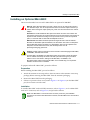
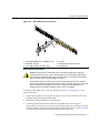
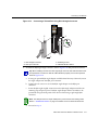
To install a DFE-Gold module, refer to Figure 3-7 and use the same procedure described
in “Installing Module into a Matrix E7 or Matrix N7 Chassis” on page 3-10. As with the E7
and N7 chassis, 7xxxxx modules cannot be installed with the 4xxxxx modules.
Caution: When setting the locking levers to the closed position, do not try to force the
locking levers to the point that they touch the face of the front panel. Forcing the locking
levers to this point could damage the module and chassis.
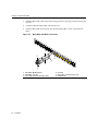
Figure 3-7
Installing Module into Matrix N3 Chassis
12
11
10
9
8
4
7
3
6
2
4
5
1
3
GROUP
SELECT
2
GROUP
1
COM
CPU
➁
DFE
7C203-1
4H4282-49
47X
4
G
R
O
U
P
37X
35X
3
G
R
O
U
P
25X
23X
2
G
R
O
U
P
13X
G
R
O
U
P
1
REDUNDANCY
11X
PWR
1X
FAST ENET
MGMT
RESET
➆
100-125V~12.0A
200-240V~6.0A
50/60 Hz
7C203-1
PWR
REDUNDANCY
100-125V~12.0A
200-240V~6.0A
50/60 Hz
➄
➃
➅
➀➂
1
2
3
4
Card guides
Slot 1 (Top slot is slot 3.)
Module card
Metal back panel
5 Upper locking tab (shown in closed position)
6 Lower locking tab (shown in closed position)
7 FTM2 backplane and power connectors
Matrix DFE-Gold Series Modules Installation Guide
3-13