1
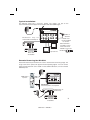
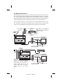
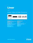
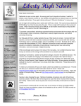
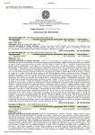
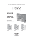
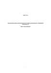
PERFORMANCE MULTI-ROOM VIDEO
3 x 8 Coax Cable Panel
DA-550BID
DA-550HHR
+15vdc
gnd
ir out
TM
DA-550BID
bi-directional 3 X 8 coax panel for cable systems
B
(pwr)
mod input
tv output
catv
A
12v, two-way multi-room ir remote control
+15vdc
gnd
ir out
PRINTER'S INSTRUCTIONS:
MANUAL DA-550HHR/BID - LINEAR P/N: 600-135 F - INK: BLACK - MATERIAL: 20 LB. MEAD BOND - SIZE: 5.500" X 8.500" - FOLDING: ALBUM FOLD - BINDING: SADDLE STITCH - SCALE: 1-1
®
TM
DA-550HHR
high headroom 3 X 8 coax panel for antenna or one-way cable systems
B
(pwr)
mod input
tv output
A
12v, two-way multi-room ir remote control
2005
600-135 F
IMAGE 1
ant/catv
Model DA-550
The DA-550 is the heart of a multi-room distribution system. The
DA-550 connects as many as 8 televisions to cable or antenna,
while maintaining compatibility with ChannelPlus video
modulators and the bi-directional, 12V, IR repeating system.
DA-550
Additional mounting ears*
Power Supply (15VDC @ 300mA)
Power/IR adaptor
+15vdc
gnd
ir out
Contents:
TM
DA-550BID
bi-directional 3 X 8 coax panel for cable systems
B
(pwr)
mod input
tv output
catv
A
*Additional mounting
ears are designed to
allow the DA-550 series
to be OpenHouse®
compatible.
12v, two-way multi-room ir remote control
Model Differences:
The DA-550HHR is for antenna or uni-directional cable systems. The HHR has
the highest headroom of any coax panel available in the market.
The DA-550BID is for bi-directional cable systems providing a 5-42MHz back
channel for cable modems or interactive set-top boxes.
Accessories:
®
VIDEO SYSTEM
POWER
15VDC
IR
EMITTERS
SYSTEM POWER
FROM
MODULATOR
Model 2010
Power injector wall plate
Powers the DA-550
remotely and has a built-in
IR wall plate.
select
A
C
model 5545 quad digital modulator
program
D
pll frequency control
Series 5500 and series SVM
modulators create local TV
channels, have built-in IR
engines and can remotely
power the DA-550.
Model 2184 IR breakout
replaces the power
supply adapter and
drives up to four IR
emitters.
TO EXPANSION PANEL
Model 2181 IR extender allows
IR signals to be passed from
one DA-550 to another.
2
600-135 F
B
IMAGE 2
Typical Installation:
+15vdc
gnd
ir out
The DA-550 works like a zero-loss splitter. The signals you put on the
antenna/CATV input will appear on the outputs with about 3dB of gain.
TM
DA-550HHR
high headroom 3 X 8 coax panel for antenna or one-way cable systems
B
CATV or
Antenna
(pwr)
mod input
Modulator may be
connected to A or B input.
ant/catv
A
RG-6 coax
recommended
for all runs
12v, two-way multi-room ir remote control
LOOP
POWER
OUTPUT
tv output
DC block 2501
needed in series
with coax when
2100A is not used
AUDIO AUDIO VIDEO
DC block
Up to 8 TVs
DVD, VCR
or Satellite
Remote Powering the DA-550
+15vdc
gnd
ir out
Put the DA-550 coax panel where the coax is: often the basement or garage. The
single coax carries power, RF signals and IR repeating signals. You can remote
power the DA-550 from series 5500 or series SVM modulators, or from a model
2010 wall plate.
TM
DA-550HHR
high headroom 3 X 8 coax panel for antenna or cable systems
VIDEO SYSTEM
2010 power
injector
POWER
15VDC
B
(pwr)
IR
EMITTERS
mod input
tv output
ant/catv
A
5v, multi-room ir remote control
SYSTEM POWER
FROM
MODULATOR
Or
Important:
To remote power, use input B.
LOOP
POWER
OUTPUT
AUDIO AUDIO VIDEO
DVD, VCR
or Satellite
600-135 F
IMAGE 3
5500 series or
SVM series
3
IR Repeating System:
With DA-550 you can also control your video devices from any room in the house.
Any or all 8 outputs may be connected to the model 2100A wall plates. The 2100A
will interface with models 2130A, 2231 & 2132 IR targets as well as a variety of
industry standard IR receivers. Direct your remote control at the IR target and the
2173 IR emitter will repeat the IR signal to the video devices in the media room.
Normally, the IR emitters are also connected to the model 2100A wall plates. But, if
the coax panel is located in the media center, you may chose to connect the
emitters to a model 2184 IR breakout panel. Both examples are shown below.
model 2100A
wall plate
Media
Center
VIDEO SYSTEM
POWER
15VDC
IR
EMITTERS
SYSTEM POWER
model 2173
IR emitter
IR signals are repeated at
media center controlling a
video product.
FROM
MODULATOR
+15vdc
gnd
ir out
model 2173
IR emitter
TM
DA-550BID
Bedroom
bi-directional 3 X 8 coax panel for cable systems
B
(pwr)
VIDEO SYSTEM
POWER
15VDC
mod input
tv output
catv
IR
EMITTERS
A
SYSTEM POWER
12v, two-way multi-room ir remote control
FROM
MODULATOR
IR target
2130A
TV with IR target connected to a
2100A wall plate.
+15vdc
gnd
ir out
2184 IR
breakout
TM
DA-550BID
bi-directional 3 X 8 coax panel for cable systems
Bedroom
B
(pwr)
mod input
tv output
catv
VIDEO SYSTEM
POWER
15VDC
A
IR
EMITTERS
12v, two-way multi-room ir remote control
SYSTEM POWER
FROM
MODULATOR
Option:
DA-550 located in the media
center. Use a model 2184 IR
breakout panel to connect the
power supply and up to 4 IR
emitters will control the video
source devices in the media
center.
IR target
2130A
TV with IR target connected to a
2100A wall plate.
4
600-135 F
IMAGE 4
IR Systems: 12V vs. 5V
●
●
●
There are two common IR repeating systems. The 12V system is very versatile
and intended for professional installation. The 12V system is compatible with
Xantech IR receivers
The DA-550 coax panels use the 12V system.
12V and 5 V IR targets are NOT interchangeable. The emitters ARE
interchangeable. The 2010 wall plate, 550 series modulations and SVM series
modulators ARE compatible with both 12V and 5V systems.
12V IR Systems: Troubleshooting
1) If IR light glows
steadily, there is noise
TARGET
+15vdc
gnd
ir out
LED
EMITTER
TM
DA-550BID
TV set
is ON
POWER
bi-directional 3 X 8 coax panel for cable systems
TO
TV
B
(pwr)
mod input
tv output
catv
A
12v, two-way multi-room ir remote control
ChannelPlus
modulator
®
select
A
B
C
model 5545 quad digital modulator
program
D
pll frequency control
2) First disconnect the coax cables from all of the television output jacks. Find the
source of the noise by re-connecting cables one at a time until the IR light glows.
This identifies that coax as a noise source. Connect this noisy coax only for the next
steps. Remember that there could be more than one source of noise, so you may
need to repeat the following steps for each coax. Now step 3 will determine which
type of noise problem you have.
TV set
is ON
Shade the target
TV set
is ON
Move the target
3a) Optical noise. Cover the target with a towel. If
the IR lights stops blinking, you have optical noise.
The target may be pointed at a window, a fluorescent
light or a plasma TV. Reposition the target so it can’t
“see” the source of IR light. If the IR light still glows,
proceed to the next step.
3b) EMI noise: TV sets are sources of EMI,
electromagnetic interference. Move the target away
from the TV and try to reposition the target so the IR
light stays off.
If the system trips the circuit breakers
(IR systems only)
+15vdc
gnd
ir out
Using DC blocks. All output ports must be connected to a 2100A wall plate OR
a DC block. If DC blocks are not used, the internal circuit breakers may trip to
protect the system. (An output port that is not used will not trip the system and
requires no DC block.)
TM
DA-550BID
bi-directional 3 X 8 coax panel for cable systems
Use a DC block on all output
ports that do not connect to
a 2100A wall plate. (IR
systems only)
B
(pwr)
mod input
DC Block
tv output
catv
A
12v, two-way multi-room ir remote control
600-135 F
IMAGE 5
5
Expanding the DA-550:
+15vdc
gnd
ir out
Master DA-550
TM
DA-550BID
bi-directional 3 X 8 coax panel for cable systems
B
(pwr)
mod input
tv output
catv
A
12v, two-way multi-room ir remote control
CATV or
Antenna
TO EXPANSION PANEL
+15vdc
gnd
ir out
Model 2181
TM
DA-550BID
bi-directional 3 X 8 coax panel for cable systems
B
mod input
tv output
+15vdc
gnd
ir out
(pwr)
catv
Up to 64 TV outlets
You may connect up to 8
more DA-550s to the
outputs of a master DA550, for a total of 64 TV
outlets. The longest
recommended coax run
should not exceed 150’.
That is a total of the coax
from master to slave and
slave to TV.
TM
DA-550BID
A
bi-directional 3 X 8 coax panel for cable systems
12v, two-way multi-room ir remote control
B
(pwr)
mod input
tv output
catv
A
12v, two-way multi-room ir remote control
Slave DA-550
Each DA-550 must be powered individually. Each slave DA-550 can have local
modulators and a zoned IR system for TVs connected to the eight outputs. Any
modulator signals injected into a slave DA-550 will be viewable only on the eight TVs
connected to it. Modulators connected to the master DA-550 will be viewable on all
TV outputs including slave DA-550s. To combine IR control signals of slave DA-550
units, use one 2181 IR extender for each slave DA-550.
(See model 2181 instruction manual)
Circuit Breaker:
The model 2010 and DA-550 have built-in circuit breakers. If any of
power LEDs are not lit, reset the circuit breaker by disconnecting
and reconnecting the power supply. If the system does not reset,
look for an installation error.
DA-550
VIDEO SYSTEM
B
POWER
15VDC
(pwr)
mod input
tv out
A
Model
2010
IR
EMITTERS
SYSTEM POWER
12v, two-way multi-room ir remote control
Power LED
FROM
MODULATOR
Power LED
6
Note: Connecting a 75ohm terminator
directly to an output of a DA-550 will cause
the circuit breaker to trip.
600-135 F
IMAGE 6
FCC Requirements:
THIS PRODUCTS COMPLIES WITH FCC REQUIREMENTS. A SYSTEM USING THIS
DEVICE WILL COMPLY WITH FCC REQUIREMENTS. USE ONLY VIDEO
MODULATORS THAT COMPLY WITH PART 15 OF THE FCC RULES AND HAVE A
25dBmV MAX OUTPUT LEVEL. FAILURE TO DO SO MAY VOID THE USER’S
AUTHORITY TO OPERATE THIS EQUIPMENT.
THE DA-550HHR IS SUITABLE FOR USE WITH AN ANTENNA OR WITH CATV
SYSTEMS.
THE DA-550BID IS SUITABLE FOR USE WITH CATV SYSTEMS.
Things To Watch For:
Herringbone interference on modulator channel (diagonal lines): You
may have chosen a channel number that is not completely vacant. Distant UHF
stations may not be watchable, but will cause interference if you try to create a
new channel at the same frequency. Also, cable companies often have extra
signals where there should be none. Try moving the modulator channel to another
number. You may have to add a low pass filter to remove the cable company noise.
If the filter does not work, try adding a DC-block to remove common mode
interference.
Herringbone interference on many channels, including modulator
channels (disappears when you remove the CATV/antenna feed): The
RF amplifier can be overloaded by abnormally strong signals. Often, you can cure
the problem with a simple attenuator. Use a variable attenuator and try to find a
signal level where the interference just disappears. Sometimes, the problem is one
station is far stronger than the rest. In this case, attenuating all of the signals with a
simple attenuator will cause the desired stations to be weak (snowy). You must
reduce the strength of the only offending station. A common FM trap will help if the
problem is a nearby FM tower. If the problem is a nearby TV station, often the
station management can provide suitable filters.
We recommend using only RG-6 coax when wiring a house. Why? Although good
RG-59 has only slightly more loss than RG-6, it is harder to find a good RG-59 with
wide bandwidth. RG-6 is a little more expensive and a little harder to run (it is
thicker). But you will avoid surprises if you stick to RG-6.
10dB
5dB
0dB
min
15dB
20dB
max
Inexpensive variable
attenuator
Inexpensive DC block
for RF
600-135 F
IMAGE 7
7
Specifications: typical @ 25°C ± 5°C
Gain:
CATV/Antenna port to output
Modulator input to output
Output to CATV (reverse)
(5-42MHz)
DA-550HHR
DA-550BID
3dB
-10dB
n/a
3dB
-10dB
-15dB
Isolation
Modulator input to CATV/Ant
>80dB
5-1000MHz
>35dB
54-1000MHz fwd
5-42MHz reverse
20dBmV(+80dBuV) 20dBmV(+80dBuV)
15 VDC @ 300mA
15 VDC @ 300mA
Max CATV/Antenna input
Power Supply (included)
General
Width x height x depth (cm)
Shipping weight
6.5” x 1.25” x 4.5”
3 lbs.
Warranty
Linear LLC warrants this product to be free from defects in material and workmanship for 5 years. The time period will be
measured using the date code labeled on the product. Linear LLC is not responsible for damage to the product resulting from
the buyer's improper handling, stocking or warehousing of the product.Any implied warranty arising from the sale of the product
including implied warranties of merchantability and fitness for purpose are limited. Linear LLC shall not be responsible for any
losses, damages or expenses, whether direct, consequential, or incidental arising from the use or the inability to use the
product.Some states and countries do not allow limitations or how long an implied warranty lasts or the exclusion or limitation or
incidental or consequential damages, so the above exclusions may not apply. The Linear LLC warranty gives specific legal
rights in addition to other rights, which may exist and vary from state to state and country to country.
The warranty is limited to repair or replacement of products returned, freight prepaid, to Linear LLC, there is NO PROVISION
FOR LABOR COST OR OTHER REIMBURSEMENTS OF ANY KIND.
1. Failures due to product abuse, such as negligence, improper use, and electrical surge including damage from lightning,
water damage or other damage due to natural disasters are not covered by the warranty. The most common form of product
abuse is surge damage caused by lightning.
2. The warranty shall also be voided by any tampering with the date code, labels or other markings on the product.
3. Products that are damaged in transit to Linear LLC due to improper packaging or by the carrier (shipping company) will not
be covered under the warranty.If the product was damaged or lost by the carrier, it is the sender's responsibility to create a claim
against the carrier.
4. The user is responsible for all labor costs associated with removing, reinstalling and returning the product to Linear LLC.
Linear LLC, at its option, will repair or replace the defective product. Replacements will be made from B-Stock, if an exact
replacement is not available, Linear LLC, at its option, will select the nearest equivalent product. The user is responsible for
freight charges to Linear LLC. Linear LLC will return warranted repaired or replacements by UPS Ground or an equivalent
service.A customer may pay the additional costs for second-day or next-day service.
All products returned for warranty service require a Return Product Authorization Number (RPA#). Contact Linear Technical
Services at 1-800-999-5225 for an RPA# and other important details.
© 2005 Linear LLC, Carlsbad, CA
600-135 F
600-135 F
IMAGE 8