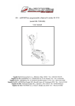
1
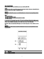
™ r Sc hwi nn®MPowe Cons ol eV2+Po we r Specifications MPower Console V2 Speed Sensor Power Requirements Power Sensor 5.25” (13.34 cm) 2.38” (6.03 cm) Patent Information: 2 Important Safety Instructions ,QGLFDWHV D SRWHQWLDOO\ KD]DUGRXV VLWXDWLRQ ZKLFK LI QRW DYRLGHG FRXOG UHVXOW LQ GHDWK RU VHULRXV LQMXU\ Before using this equipment, obey the following warnings: Read and understand the complete Owner’s Manual. Keep Owner’s Manual for future reference. 5HDG DQG XQGHUVWDQG DOO ZDUQLQJV RQ WKLV PDFKLQH ,I DW DQ\ WLPH WKH :DUQLQJ VWLFNHUV EHFRPH ORRVH XQUHDGDEOH RU GLVORGJHG FRQWDFW6WDLU0DVWHU &XVWRPHU 6HUYLFH IRU UHSODFHPHQW VWLFNHUV s &KLOGUHQ PXVW QRW EH OHW RQ RU QHDU WR WKLV PDFKLQH 0RYLQJ SDUWV DQG RWKHU IHDWXUHV RI WKH PDFKLQH FDQ EH GDQJHURXV WR FKLOGUHQ &RQVXOW D SK\VLFLDQ EHIRUH \RX VWDUW DQ H[HUFLVH SURJUDP 6WRS H[HUFLVLQJ LI \RX IHHO SDLQ RU WLJKWQHVV LQ \RXU FKHVW EHFRPH VKRUW RI EUHDWK RU IHHO IDLQW &RQWDFW \RXU GRFWRU EHIRUH \RX XVH WKH PDFKLQH DJDLQ 8VH WKH YDOXHV FDOFXODWHG RU PHDVXUHG E\ WKH PDFKLQH¶V FRPSXWHU IRU UHIHUHQFH SXUSRVHV RQO\ ,I \RX KDYH D SDFHPDNHU RU RWKHU LPSODQWHG HOHFWURQLF GHYLFH FRQVXOW \RXU GRFWRU EHIRUH XVLQJ D ZLUHOHVV FKHVW VWUDS RU RWKHU WHOHPHWULF KHDUW UDWH PRQLWRU 'R QRW XVH RU SXW WKH PDFKLQH LQWR VHUYLFH XQWLO WKH PDFKLQH KDV EHHQ IXOO\ DVVHPEOHG DQG LQVSHFWHG IRU FRUUHFW SHUIRUPDQFH LQ DFFRUGDQFH ZLWK WKH 2ZQHU¶V 0DQXDO 5HDG DQG XQGHUVWDQG WKH FRPSOHWH 2ZQHU¶V 0DQXDO VXSSOLHG ZLWK WKH PDFKLQH EHIRUH ILUVW XVH .HHS WKH 2ZQHU¶V DQG $VVHPEO\ 0DQXDOV IRU IXWXUH UHIHUHQFH FCC Compliance &KDQJHV RU PRGLILFDWLRQV WR WKLV XQLW QRW H[SUHVVO\ DSSURYHG E\ WKH SDUW\ UHVSRQVLEOH IRU FRPSOLDQFH FRXOG YRLG WKH XVHU¶V DXWKRULW\ WR RSHUDWH WKH HTXLSPHQW Note: TKLV GHYLFH FRPSOLHV ZLWK 3DUW RI WKH )&& 5XOHV 2SHUDWLRQ LV VXEMHFW WR WKH IROORZLQJ WZR FRQGLWLRQV WKLV GHYLFH PD\ QRW FDXVH KDUPIXO LQWHUIHUHQFH DQG WKLV GHYLFH PXVW DFFHSW DQ\ LQWHUIHUHQFH UHFHLYHG LQFOXGLQJ LQWHUIHUHQFH WKDW PD\ FDXVH XQGHVLUHG RSHUDWLRQ 7KHVH OLPLWV DUH GHVLJQHG WR SURYLGH UHDVRQDEOH SURWHFWLRQ DJDLQVW KDUPIXO LQWHUIHUHQFH LQ D UHVLGHQWLDO LQVWDOODWLRQ 7KLV HTXLSPHQW JHQHUDWHV XVHV DQG FDQ UDGLDWH UDGLR IUHTXHQF\ HQHUJ\ DQG LI QRW LQVWDOOHG DQG XVHG LQ DFFRUGDQFH ZLWK WKH LQVWUXFWLRQV PD\ FDXVH KDUPIXO LQWHUIHUHQFH WR UDGLR FRPPXQLFDWLRQV +RZHYHU WKHUH LV QR JXDUDQWHH WKDW LQWHUIHUHQFH ZLOO QRW RFFXU LQ D SDUWLFXODU LQVWDOODWLRQ ,I WKLV HTXLSPHQW GRHV FDXVH KDUPIXO LQWHUIHUHQFH WR UDGLR RU WHOHYLVLRQ UHFHSWLRQ ZKLFK FDQ EH GHWHUPLQHG E\ WXUQLQJ WKH HTXLSPHQW RII DQG RQ WKH XVHU LV HQFRXUDJHG WR WU\ WR FRUUHFW WKH LQWHUIHUHQFH E\ RQH RU PRUH RI WKH IROORZLQJ PHDVXUHV 5HRULHQW RU UHORFDWH WKH UHFHLYLQJ DQWHQQD ,QFUHDVH WKH VHSDUDWLRQ EHWZHHQ WKH HTXLSPHQW DQG UHFHLYHU &RQVXOW WKH GHDOHU RU DQ H[SHULHQFHG UDGLR79 WHFKQLFLDQ IRU KHOS 3 4 A1 A2 A3 A7 A6 A5 A4 5 A1 KM / MPH (Speed) A5 STAGE Time and Distance A2 WATTS (Power) A6 RPM (Cadence) A3 KCAL (Calories) A7 Heart Rate A4 TOTAL Time and Distance Note: If you need to change the measurement units to English Imperial or metric, refer to the User Setup section of this manual. 6SHHG The Speed display field shows the estimated speed of the bike in kilometers per hour (KM/H) or miles per hour (MPH). To view the average speed during Workout Mode, tap the AVG/END button. :DWWV The WATTS display field shows the power that you are producing at the current resistance level (1 horsepower = 746 watts). WATTS data only shows if there is a power sensor installed on the bike. To see the average watts during Workout Mode, tap the AVG/END button. +HDUW 5DWH The Heart Rate display field shows the heart rate in beats per minute (BPM) from the heart rate monitor (HRM). The heart icon flashes when the console receiver senses the HRM signal. If the console receiver does not sense the HRM, the center of the heart icon is on solid. If the console receiver senses an Ant+ HRM signal, there is an outline around the heart icon. The outline does not flash. If the HRM signal is a standard EM 5kHz pulse signal, there is not an outline around the icon. To see your average heart rate during Workout Mode, tap the AVG/END button. Consult a physician before you start an exercise program. Stop exercising if you feel pain or tightness in your chest, become short of breath, or feel faint. Contact your doctor before you use the machine again. Use the values calculated or measured by the machine’s computer for reference purposes only. &DORULHV The Calories display field shows the estimated calories that you have burned during the exercise. If the bike does not have a Power Sensor, the console calculates the calories from the heart rate data from the HRM. 530 The RPM display field shows the current pedal revolutions per minute (RPM). To see the average RPM during Workout Mode, tap the AVG/END button. For bikes that do not have a Power Sensor installed, the RPM field is also the user weight input field during User Setup Mode. The console will show error messages in this field if an error occurs. :RUNRXW 6WDJH The STAGE display field shows the time and distance in the current Stage of the workout. The display values start at zero and count forward until the end of the Stage. At each Stage in the workout, the Stage icon shows the Stage number with the number of segments that are on: 6 Workout Totals 7KH 727$/ GLVSOD\ ILHOG VKRZV WKH WRWDO WLPH DQG GLVWDQFH UHVXOWV DW WKH HQG RI WKH ZRUNRXW 7KH 7RWDO LFRQ LV OLW GXULQJ :RUNRXW 0RGH LCD + and – Icons 7KH DQG ± SOXV DQG PLQXV LFRQV RQ WKH /&' IODVK WR SURPSW WKH XVHU WR HQWHU WKHLU ZHLJKW GXULQJ 8VHU 6HWXS 0RGH 7KH LFRQV WXUQ RII ZKHQ QRW LQ XVH Keypad 7KH PXOWLIXQFWLRQ NH\SDG OHWV \RX VHW WKH FRQVROH PHDVXUHPHQWV IRU \RXU ZRUNRXW VHH DQG XSGDWH \RXU ZRUNRXW GDWD DQG H[DPLQH WKH FRQVROH GLDJQRVWLF PHVVDJHV 7DS DQ\ EXWWRQ WR DFWLYDWH WKH FRQVROH IURP 6OHHS 0RGH 7KH 2SHUDWLRQV VHFWLRQ RI WKLV PDQXDO JLYHV WKH SURFHGXUHV IRU XVLQJ WKH EXWWRQV LQ HDFK 2SHUDWLRQV PRGH 7KH %DFNOLJKW EXWWRQ VHWV \RXU VHOHFWLRQV LQ 8VHU 6HWXS 0RGH DQG 6HUYLFH 0RGH Alerts 7KH &RQVROH LFRQV DQG /&' GLVSOD\ PHVVDJHV VKRZ WKH VWDWXV RI WKH FRQVROH DQG VHQVRU RSHUDWLRQV Battery Level 7KH %DWWHU\ /HYHO LFRQ VKRZ WKH EDWWHU\ OHYHO IRU HDFKFRPSRQHQWRIWKHFRQVROHVHQVRU V\VWHP $OO VHJPHQWV RI WKH LFRQ DUH RQ ZKHQ WKH EDWWHU\ OHYHO LV KLJK :KHQ WKH EDWWHU\ OHYHO LV ORZ RQO\ WKH ERWWRP VHJPHQW LV RQ 7KH ERWWRP VHJPHQW IODVKHV ZKHQ EDWWHU\ OHYHO LV YHU\ ORZ If the battery level is too low to continue operation, the console display flashes the message "LO batt" and the console goes into Sleep Mode. If this occurs during a workout, the workout stops and the console display shows the workout results for 10 second. Then the "LO batt" message shows and the console goes into Sleep Mode. 7 Errors Error messages tell you when there is a problem in the bike's operation: 8 When the Cadence decreases to less than 5 RPM for 3 seconds or more, the console pauses and the LCD Display shows the last workout data values. If you stay paused for more than 5 minutes, the workout stops and the console goes to Display Results mode. To set the STAGE time and STAGE distance back to zero for a new stage in the workout, tap the STAGE button. The TOTAL time and TOTAL distance continue the total measurement for the workout. To end the workout, push the AVG/END button and hold for 3 seconds. The console goes to Display Results mode. Operations Sleep Mode 7KH FRQVROH DXWRPDWLFDOO\ JRHV LQWR 6OHHS 0RGH WR FRQVHUYH WKH EDWWHU\ LI WKHUH LV QR DFWLYLW\ IRU VHFRQGV DIWHU 8VHU 6HWXS DIWHU 'LVSOD\ 5HVXOWV LI :RUNRXW 0RGH SDXVHV DQG WKHUH LV QR DFWLYLW\ IRU PLQXWHV 3XVK DQ\ EXWWRQ WR DFWLYDWH WKH FRQVROH IURP 6OHHS 0RGH User Setup :KHQ WKH FRQVROH LV LQ 6OHHS 0RGH SXVK DQ\ EXWWRQ WR JR WR 8VHU 6HWXS PRGH 'XULQJ 8VHU 6HWXS 0RGH WKH FRQVROH FROOHFWV WKH QHFHVVDU\ XVHU GDWD WR FDOFXODWH DQG UHFRUG \RXU ZRUNRXW GDWD 3UR[LPLW\ OLQNLQJ WR WKH XVHU¶V +50 RU $QW ZDWFK RFFXUV ZKLOH LQ 8VHU 6HWXS ,I WKH FRQVROH GRHV QRW ILQG D 86% VWRUDJH GHYLFH RU $QW ZDWFK WKH DUURZ LFRQV RQ WKH FRQVROH EOLQN 8VH WKH DSSURSULDWH LQVWUXFWLRQ IRU \RXU PRQLWRULQJ HTXLSPHQW 86% VWRUDJH GHYLFH²LQVWDOO WKH GHYLFH LQ WKH 86% SRUW :KHQ WKH FRQVROH VHQVHV WKH GHYLFH WKH 86% DUURZ LQGLFDWRU VWD\V RQ • $QW ZDWFK²OLQN WR WKH FRQVROH 0RYH WKH ZDWFK WR ± ± FP RU OHVV IURP WKH $QW /LQN +HUH ORJR RQ WKH FRQVROH DQG KROG LW WKHUH XQWLO WKH DUURZ VWD\V RQ 7KH $QW DUURZ DQG ZDWFK LQGLFDWRUV FRPH RQ ZKHQ SUR[LPLW\ OLQNLQJ LV FRPSOHWH • $QW +50²OLQN WR WKH FRQVROH /HDQ LQWR WKH FRQVROH VR WKDW WKH +50 LV ± ± FP IURP WKH $QW /LQN +HUH ORJR XQWLO WKH DUURZ VWD\V RQ 7KH $QW DUURZ LQGLFDWRU FRPHV RQ ZKHQ SUR[LPLW\ OLQNLQJ LV FRPSOHWH ,I WKH $QW LQGLFDWRU LV QRW RQ WKH FRQVROH XVHV (0 N+] VLJQDO WR FDOFXODWH +50 Note: ,I \RX KDYH DQ $QW 6SRUW :DWFK DQG SDLUHG $QW +50 LW LV RQO\ QHFHVVDU\ IRU WKH WKH FRQVROH WR OLQN ZLWK WKH VSRUW ZDWFK +RZHYHU LI \RX KDYH DQ $QW 6SRUW :DWFK DQG (0 N+] +50 WKH FRQVROH OLQNV WR WKH ZDWFK DQG WKH +50 9 Ant+ Watch HRM )RU ELNHV WKDW GR QRW KDYH D 3RZHU 6HQVRU LQVWDOOHG XVHU ZHLJKW GDWD LV QHFHVVDU\ WR FDOFXODWH WKH &DORULHV GXULQJ WKH ZRUNRXW ,I WKH FRQVROH GRHV QRW JHW WKH ZHLJKW GDWD IURP D GHYLFH \RX PXVW PDQXDOO\ VHW WKH ZHLJKW YDOXH 7KH DQG ± LFRQV RQ WKH /&' IODVK DQG WKH 530 ILHOG GLVSOD\V OEV NJ 8VH WKH 67$*( ± DQG $9*(1' EXWWRQV WR DGMXVW WKH QXPEHU WR \RXU ZHLJKW Note: 7R FKDQJH WKH ZHLJKW XQLWV WR (QJOLVK ,PSHULDO RU PHWULF 3XVK WKH 67$*( DQG $9*(1' EXWWRQV IRU VHFRQGV WR JR WR 6HUYLFH 0RGH 7DS WKH $9*(1' EXWWRQ XQWLO \RX VHH WKH 81 PHQX RSWLRQ DQG SXVK WKH %DFNOLJKW EXWWRQ 3XVK WKH 67$*( RU $9*(1' EXWWRQ WR VHH WKH 81 PHQX RSWLRQV²81 PHWULF DQG 81 ,PSHULDO 3XVK WKH %DFNOLJKW EXWWRQ WR VHW WKH XQLWV PHDVXUH 7KH FRQVROH JRHV EDFN WR WKH 6HUYLFH 0RGH PHQX DQG WKH 81 PHQX RSWLRQ DSSHDUV 7DS WKH 67$*( RU $9*(1' EXWWRQ XQWLO \RX VHH WKH ³± ±´ H[LW RSWLRQ LQ WKH 6HUYLFH 0HQX 3XVK WKH %DFNOLJKW EXWWRQ WR JR EDFN WR 8VHU 6HWXS 0RGH 3XVK WKH %DFNOLJKW EXWWRQ WR UHFRUG \RXU ZHLJKW 'XULQJ 8VHU 6HWXS ZKLOH 530 LV OHVV WKDQ LW LV SRVVLEOH WR ORVH WKH SUR[LPLW\ OLQNLQJ WR DQ $QW ZDWFK RU $QW +50 LI \RX PRYH WRR IDU DZD\ IURP WKH &RQVROH ,I WKLV RFFXUV IRU WKH $QW ZDWFK WKH $QW ZDWFK LQGLFDWRU IODVKHV ,I WKLV RFFXUV IRU WKH $QW +50 WKH +5 GLVSOD\ ILHOG VKRZV ]HUR <RX PXVW GR WKH SUR[LPLW\ OLQNLQJ SURFHGXUH DJDLQ ,I :RUNRXW 0RGH GRHV QRW VWDUW LQ VHFRQGV WKHUH LV QR NH\SDG DFWLYLW\ DQG 530 LV OHVV WKDQ WKH FRQVROH UHWXUQV WR 6OHHS 0RGH Workout Mode $IWHU 8VHU 6HWXS LV FRPSOHWH VWDUW SHGDOLQJ WKH ELNH :KHQ WKH &DGHQFH 530 LQFUHDVHV WR 530 RU PRUH WKH FRQVROH JRHV LQWR :RUNRXW 0RGH 7KH :RUNRXW 67$*( DQG 727$/ LFRQV FRPH RQ DQG WKH ZRUNRXW PHDVXUHPHQWV VWDUW 10 Display Results Device Pairing 2. Push the STAGE and AVG/END buttons for 5 seconds to go to Service Mode. 3. Tap the AVG/END button until you see the Power menu option, and push the Backlight button. 4. Push the STAGE or AVG/END button to see the Power submenu options—Sport (not power enabled) and Perform (power enabled). • If you have a Power Sensor, go to the Perform option and push the Backlight button to set. • If there is no Power Sensor, go to the Sport option and push the Backlight button to set. 5. The console goes back to the Service Mode menu and the Power menu option appears. 6. Make sure that the switch (U) on the Speed Sensor is set to S (speed). 7. Push the pairing buttons on the Console (L1), the Speed Sensor (L2) and the Power Sensor (L3), if applicable. 8. The console display shows PPP and the time display counts down from 0:35 (seconds). 11 A43 A48 A44 A47 A45 A46 A43 Pairing A47 Countdown Timer (Power Sensor) A44 Countdown Timer (Speed Sensor) A48 Pairing Indicator A45 Process Status (Speed Sensor) A46 Process Status (Power Sensor) 9. The Process Status indicator(s) on the console display shows “– – –” while the Pairing operation continues. If Pairing is completed satisfactorily, the console display shows PASS. The circuit board inside the Power Sensor cover has 2 color LEDs — 1 green and 1 red. The 2 LEDs come on during the Pairing operation. While the operation continues satisfactorily, the green LED is on. When Pairing is completed satisfactorily, both LEDs turn off. If the Pairing operation is not completed satisfactorily, only the red LED stays on. If the Pairing operation is not completed satisfactorily, the console display shows FAIL. Push the pairing button on the console (L1). Then do the Device Pairing procedure again. 10. When the Pairing procedure is completed, push the Backlight button to go back to the Service Menu. If the Pairing operation was not completed satisfactorily, the console display shows the pairing button on the console (L1). Then do the Device Pairing procedure again. P– – menu option again. Push the 11. Tap the STAGE or AVG/END button until you see the “– – –” (exit) option in the Service Menu, and push the Backlight button. 12. Install the console and sensors on the bike. Refer to the MPower™ installation guides. Device Pairing for Multiple Bikes For Schwinn A.C.™ bikes with MPower™ Consoles in a group setting, make sure to set up Device Pairing for only one bike at a time to prevent crosstalk between the devices on different bikes. NOTICE: When you remove the handlebars (with console) to clean them, make sure that you install them again on the same bike to keep the Device Pairing correct. If you install the handlebars and console on a different bike, the console does not read data from the correct sensors. Recommendation: You can put number labels on the bikes and handlebars to make sure that the Device Pairing stays correct. 12 13 14 When you select the submenu option for a specific battery (AP1, AP2, or AP3), the console shows the level of that battery. Battery Status Icon Console Speed Sensor Power Sensor Voltage 4 segments 80–100% 80–100% 1.5V or more 3 segments 60–80% 60–80% 1.3–1.499V 2 segments 40–60% 40–60% 1.1–1.299V 1 segment 20–40% 20–40% 0.9–1.099V 1 segment flashing less than 20% less than 20% less than 0.9V If the battery level is low, refer to the instructions for battery replacement in this manual. SyVteP 7KLVRSWLRQLQWKH6HUYLFH 0RGH PHQX OHWV \RX LQVSHFW PDLQWHQDQFH GDWD LQ WKH FRQVROH DQG DGMXVW VHWWLQJV LQ WKH ((3520 ILUPZDUH WKURXJK WKH VXEPHQX RSWLRQV 6XPPDU\²&RQVROH VHWXS VXPPDU\ 5HVHW²&RQVROH ³5HVHW´ IXQFWLRQ IRU WHFKQLFLDQ WR XSGDWH WKH ILUPZDUH $FWLYH530²$FWLYH VSHHG RSWLRQ OHWV \RX FKDQJH WKH 530 WKUHVKROG GHIDXOW YDOXH IRU WKH FRQVROH WR VWDUW :RUNRXW 0RGH (UURU+LVWRU\²(UURU KLVWRU\ %DFNOLJKW²%DFNOLJKW RSWLRQV %DFN²([LW 6XPPDU\ Displays usage hourVGLVWDQFHDQGFRQVROH ILUPZDUHYHUVLRQ 15 Error History $OORZVUHYLHZRIHUURUORJ A1 A2 A3 A1 A2 Error Message Error Count A3 Error Sequence If the battery level is low, refer to the instructions for battery replacement in this manual. 6\VWHP (UURU0HVVDJH7KHHUURUPHVVDJHVKRZVDV([[,IWKHUHLVQRHUURUFXUUHQWRSHUDWLRQLVFRPSOHWHGFRUUHFWO\WKHGLVSOD\VKRZVDV (UURU&RXQW1XPEHURIWLPHVWKDWHUURURFFXUUHG (UURU6HTXHQFH6HTXHQFHLQHUURUKLVWRU\LVQHZHVWLVROGHVW Tap the STAGE or AVG/END button to look through the sequence of error messages in the error history. Push and hold the AVD/END button for 3 seconds to clear the Error Count for the specified error message. 16 Backlight Allows changes to Backlight functions. Timer: Sets the operation so that you must push the Backlight button to turn on the backlight. The length of time the backlight stays on can be adjusted. ON: Sets the operation so that the backlight comes on and stays on when the console is on. USB This option on the Service Mode menu sets the USB function to: ON or OFF The Export Data option is only for the Service Technician to download system data (EP0 and EPN display data) to a USB device. Data Export to USB Storage Device To record the console system data on a USB storage device, connect the USB device to the console and go to the U03 option Allows changes to Backlight functions. 17 IC Class Setup To use Schwinn A.C.™ bikes with MPower™ consoles in a group setting, make sure to leave sufficient space between the bikes to prevent interference in the proximity linking of the console and the rider’s HRM and Ant+ Sport Watch. Refer to the IC class floorplan below for the distance between bikes. Z1 The proximity linking zone for the console and the HRM and Ant+ Sport Watch and HRM. Z2 The tracking zone for the console to sense the HRM and Ant+ Sport watch after proximity linking is complete. Note: The tracking zone for an EM 5kHz HRM is approximately 28" (70 cm). 18 Maintenance Equipment must be regularly examined for damage and repairs. The owner is responsible to make sure that regular maintenance is done. Worn or damaged components must be replaced immediately or the equipment removed from service until the repair is made. Only manufacturer supplied components can be used to maintain and repair the equipment. This product, its packaging, and components contain chemicals known to the State of California to cause cancer, birth defects, or reproductive harm. This Notice is provided in accordance with California’s Proposition 65. If you would like additional information, please refer to our Web site at www.nautilus.com/prop65 Before each use, inspect the exercise machine for loose, broken, damaged, or worn parts. Do not use if found in this condition; repair or replace all parts at the first sign of wear or damage. After each use, use a damp cloth to wipe your equipment and computer free of sweat. Important: To avoid damaging the finish on your bike and console, never use a petroleum-based solvent when cleaning. Avoid getting excessive moisture on the console. Replace the batteries every 1 year (as necessary): • • • Console — (2) C batteries (LR14) Speed Sensor — (1) CR2032 battery Power Sensor (if installed) — (1) AA battery (LR6) Replacing the Console Batteries If you need to replace the batteries in the console: • • • • • • Remove the screw that attaches the end of the console bracket to the back of the console. Move the console up along the console bracket to open the battery bay. Remove the old batteries. Put the new batteries in the console. Make sure that they point in the correct direction (+ and –). Move the console down the console bracket to close the battery bay. Attach the console to the console bracket with the screw. Replacing the Speed Sensor Battery If you need to replace the batteries in the speed sensor: • • • • • • • Remove the 2 screws that attach the speed sensor to the front of the chainguard. Remove the small screw that attaches the inner sensor housing to the outer housing. Slide the inner housing off the outer housing. The battery holder is in the inner housing. Carefully slide the old battery out of the battery holder. Carefully slide the new battery into the battery holder. Make sure that you can see the + icon on the battery. Install the inner sensor housing to the outer housing with the small screw. Attach the sensor to the chainguard with the 2 screws. 20 Replacing the Power Sensor Battery This procedure is only for bikes that have the Power Sensor upgrade installed. If you need to replace the batteries in the Power Sensor, refer to the Schwinn® MPower™ Power Upgrade Installation Guide: • • • • • • Remove the 2 screws that attach the Power Sensor to the Brake Carriage. Remove the gasket from the outer sensor housing. Remove the old battery from the battery bay. Put the new battery in the battery bay. Make sure that it points in the correct direction (+ and –). Put the gasket back on the outer housing . Attach the Power Sensor to the Brake Carriage with the 2 screws. Troubleshooting Condition/Problem Check Solution Console does not come on No batteries or dead batteries Replace batteries. Speed display is not accurate Display set to wrong unit of measure. (English/Metric) Go to Service Mode menu and change the Units configuration. Power display is not accurate Range of Watt values Do the Full Up Position calibration. If the power display is still not accurate, replace the Power Sensor. No Speed display Speed Sensor Make sure Speed Sensor is installed. Make sure that the Speed Sensor can sense the magnet in the flywheel. Replace Speed Sensor battery. No Power display Power Sensor Make sure Power Sensor is installed. Replace Power Sensor battery. No Heart Rate display while using chest strap Transmitter contact with skin Moisten skin contact area on the chest strap. Electromagnetic interference Turn off any television, AM radio, microwave, or computer within 6 feet (2 meters) of the bike. Chest strap transmitter Test chest strap with another HRM device such as HR watch or a machine at a gym. If transmitter has good skin contact and still does not send a HR signal, replace chest strap transmitter. HR receiver If chest strap is known to work with other devices and no sources of interference are present, or console is tested with a Pulse Simulator and does not receive the signal, contact Nautilus Customer Care. Note: The LCD display is different for Errors that occur during Service Mode and Errors during non-Service Mode. Error Code E00 Condition/Problem Solution Push the pairing button on the back of the Console, Console did not pair with Speed Sensor correctly. (This error only occurs after Device Pairing was not completed Speed Sensor and Power Sensor (if applicable) and try the Device Pairing procedure again. satisfactorily.) Replace all batteries, and try the Device Pairing procedure again. E01 Push the pairing button on the back of the Console, Console did not pair with Power Sensor correctly. (This error only occurs after Device Pairing was not completed Speed Sensor and Power Sensor (if applicable) and try the Device Pairing procedure again. satisfactorily.) Replace all batteries, and try the Device Pairing procedure again. 22 E02 Power Sensor did not pair with Speed Sensor correctly. Push the pairing button on the back of the Console, Speed Sensor and Power Sensor (if applicable) and try (This error only occurs after Device Pairing was not the Device Pairing procedure again. completed satisfactorily.) Replace all batteries, and try the Device Pairing procedure again. Battery low on Console or Speed Sensor Do a Battery Level check. Interference from the adjacent area Turn off any television, AM radio, microwave, or computer within 6 feet (2 meters) of the bike, or move the bike. Battery low on Console or Power Sensor Do a Battery Level check. Interference from the adjacent area Turn off any television, AM radio, microwave, or computer within 6 feet (2 meters) of the bike, or move the bike. E07 Tilt Sensor Calibration was not done. Go to Service Mode menu,C- - submenu, C01 option. Call StairMaster Customer Care. E08 Tilt Sensor Calibration is incorrect or out of date Go to Service Mode menu, C- - submenu, C01 option. Call StairMaster Customer Care. E09 USB disabled due to low battery Replace Console batteries, and go to Service Mode,U- submenu,U02 option. E10 No signal from Power Sensor Change the Brake position and pedal the bike for a few seconds to turn on the Power Sensor. E12 EEPROM error Remove the console batteries and install them again. If that does not work, call StairMaster Customer Care. E13 Power Sensor is paired to the wrong Speed Sensor. Do the Device Pairing procedure again. E14 Console wireless module not able to transmit/receiv Replace console. Call StairMaster Customer Care. E03 E04 23 Contacts NORTH AMERICA CUSTOMER SERVICE Tel: 888-678-2476 E-mail: [email protected] CORPORATE HEADQUARTERS StairMaster World Headquarters 4400 NE 77th Ave, Suite 300 Vancouver, WA, USA 98662 Tel: 888-678-2476 24 25