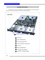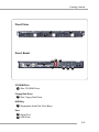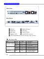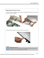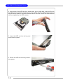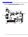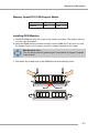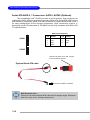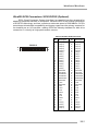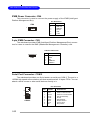
1
MS-9246 1U Rackmount Server English Version G52-S9246X1 i Manual Rev: 1.0 Release Date: July 2004 FCC-A Radio Frequency Interference Statement This equipment has been tested and found to comply with the limits for a class A digital device, pursuant to part 15 of the FCC rules. These limits are designed to provide reasonable protection against harmful interference when the equipment is operated in a commercial environment. This equipment generates, uses and can radiate radio frequency energy and, if not installed and used in accordance with the instruction manual, may cause harmful interference to radio communications. Operation of this equipment in a residential area is likely to cause harmful interference, in which case the user will be required to correct the interference at his own expense. Notice 1 The changes or modifications not expressly approved by the party responsible for compliance could void the user’s authority to operate the equipment. Notice 2 Shielded interface cables and A.C. power cord, if any, must be used in order to comply with the emission limits. VOIR LA NOTICE D’INSTALLATION AVANT DE RACCORDER AU RESEAU. Micro-Star International MS-9246 This device complies with Part 15 of the FCC Rules. Operation is subject to the following two conditions: (1) this device may not cause harmful interference, and (2) this device must accept any interference received, including interference that may cause undesired operation. ii Copyright Notice The material in this document is the intellectual property of MICRO-STAR INTERNATIONAL. We take every care in the preparation of this document, but no guarantee is given as to the correctness of its contents. Our products are under continual improvement and we reserve the right to make changes without notice. Trademarks All trademarks are the properties of their respective owners. Intel ® and Pentium® are registered trademarks of Intel Corporation. PS/2 and OS ® /2 are registered trademarks of International Business Machines Corporation. Windows® 95/98/2000/2003/NT/XP are registered trademarks of Microsoft Corporation. Netware ® is a registered trademark of Novell, Inc. Award® is a registered trademark of Phoenix Technologies Ltd. AMI® is a registered trademark of American Megatrends Inc. Revision History Revision V1.0 Revision History First release Date July 2004 Technical Support If a problem arises with your system and no solution can be obtained from the user’s manual, please contact your place of purchase or local distributor. Alternatively, please try the following help resources for further guidance. Visit the MSI website for FAQ, technical guide, BIOS updates, driver updates, and other information: http://www.msi.com.tw/program/service/faq/ faq/esc_faq_list.php Contact our technical staff at: [email protected] iii Safety Instructions 1. Always read the safety instructions carefully. 2. Keep this User’s Manual for future reference. 3. Keep this equipment away from humidity. 4. Lay this equipment on a reliable flat surface before setting it up. 5. The openings on the enclosure are for air convection hence protects the equipment from overheating. DO NOT COVER THE OPENINGS. 6. Make sure the voltage of the power source and adjust properly 110/220V before connecting the equipment to the power inlet. 7. Place the power cord such a way that people can not step on it. Do not place anything over the power cord. 8. Always Unplug the Power Cord before inserting any add-on card or module. 9. All cautions and warnings on the equipment should be noted. 10. Never pour any liquid into the opening that could damage or cause electrical shock. 11. If any of the following situations arises, get the equipment checked by a service personnel: h h h h The power cord or plug is damaged. Liquid has penetrated into the equipment. The equipment has been exposed to moisture. The equipment has not work well or you can not get it work according to User’s Manual. h The equipment has dropped and damaged. h The equipment has obvious sign of breakage. 12. DO NOT LEAVE THIS EQUIPMENT IN AN ENVIRONMENT UNCONDITIONED, STORAGE TEMPERATURE ABOVE 600 C (1400F), IT MAY DAMAGE THE EQUIPMENT. CAUTION: Danger of explosion if battery is incorrectly replaced. Replace only with the same or equivalent type recommended by the manufacturer. iv CONTENTS FCC-A Radio Frequency Interference Statement .......................................................... ii Copyright Notice ........................................................................................................... iii Trademarks .................................................................................................................... iii Revision History ............................................................................................................ iii Technical Support .......................................................................................................... iii Safety Instructions ........................................................................................................ v Chapter 1. Getting Started .................................................................................... 1-1 Packing Checklist ................................................................................................ 1-2 System Overview ............................................................................................... 1-4 Top View ..................................................................................................... 1-4 Front View .................................................................................................. 1-4 Front Bezel .................................................................................................. 1-4 Rear Bezel ................................................................................................. 1-10 Rear View ................................................................................................. 1-10 System Specifications ...................................................................................... 1-12 Mainboard Layout ............................................................................................. 1-16 MSI Special Features ........................................................................................ 1-17 PC Alert™ III .............................................................................................. 1-17 Chapter 2. System Hardware ............................................................................... 2-1 System Assembly Flowchart ............................................................................. 2-2 System Assembly ............................................................................................... 2-4 Removing the Chassis Cover ..................................................................... 2-4 Replacing the Chassis Cover ..................................................................... 2-5 CPU, Heatsink, and Fan Duct ...................................................................... 2-6 Memory Bus Features ................................................................................ 2-8 DDR Memory ............................................................................................... 2-8 Memory Population Rules ............................................................................ 2-9 PCI Expansion Card ................................................................................... 2-10 PCI Riser Card (Optional) .......................................................................... 2-12 SCSI HDD ................................................................................................... 2-13 Rack Mounting .................................................................................................. 2-17 Chassis Ears ............................................................................................ 2-17 Chassis Rails ........................................................................................... 2-18 Rack Rails .................................................................................................. 2-20 Cable Arm (Optional) ................................................................................ 2-21 Chassis into the Rack ............................................................................... 2-23 Chassis off the Rack ................................................................................ 2-24 v Chapter 3. Mainboard Hardware ......................................................................... 3-1 Quick Components Guide ................................................................................... 3-2 Central Processing Unit: CPU ............................................................................. 3-3 CPU Installation Procedures for Socket 604 .............................................. 3-4 Memory ............................................................................................................... 3-5 Memory Bus Features ................................................................................ 3-5 Memory Population Rules ............................................................................ 3-6 Installing DDR Modules ................................................................................ 3-7 Memory Speed/CPU FSB Support Matrix ................................................... 3-7 Power Supply ..................................................................................................... 3-8 SSI 24-Pin Power Connector: JPWR1 ........................................................ 3-8 Connectors ......................................................................................................... 3-9 Front USB Connector: USB1 ....................................................................... 3-9 Serial ATA RAID 0, 1 Connectors: SATA1, SATA2 (Optional) ................. 3-10 Ultra320 SCSI Connectors: SCSI1/SCSI2 (Optional) ................................ 3-11 IPMB Power Connector: CN4 .................................................................... 3-12 5-pin IPMB Connector: CN3 ....................................................................... 3-12 Serial Port Connector: COM 2 ................................................................... 3-12 Jumpers ............................................................................................................ 3-13 Clear CMOS Jumper: JBAT1 ..................................................................... 3-13 BIOS Recovery Jumper: CN6 .................................................................... 3-14 Clear BIOS Password Jumper: J7 ............................................................ 3-14 Clear Event Log Jumper: J8 ...................................................................... 3-14 Slots .................................................................................................................. 3-15 SO DIMM (Small Outline DIMM) .................................................................. 3-15 PCI (Peripheral Component Interconnect) Slots ....................................... 3-15 Chapter 4. BIOS Setup ........................................................................................... 4-1 Entering Setup .................................................................................................... 4-2 Control Keys ............................................................................................... 4-2 Getting Help ................................................................................................. 4-3 General Help <F1> ...................................................................................... 4-3 The Menu Bar ..................................................................................................... 4-4 Main ..................................................................................................................... 4-6 System Summary ................................................................................................ 4-8 Advanced ........................................................................................................... 4-9 IPMI (Optional) ................................................................................................... 4-16 Security ............................................................................................................. 4-19 Boot ................................................................................................................... 4-21 Exit ..................................................................................................................... 4-22 vi Appendix A: SCSI BIOS Setup (Optional) .......................................................... A-1 Entering SCSI BIOS ............................................................................................ A-2 Control Keys .............................................................................................. A-2 Selecting the SCSI Channel ....................................................................... A-2 Selecting the Management Type ................................................................ A-2 Configure/View SCSI Controller Settings .......................................................... A-4 SCSI Bus Interface Definitions .................................................................. A-4 Additional Options ...................................................................................... A-5 BIOS Information ........................................................................................ A-8 Disk Utilities ........................................................................................................ A-9 Appendix B: Adaptec SATA RAID Utility for Intel ICH5R (Optional) ............... B-1 Introduction ........................................................................................................ B-2 1. Overview ............................................................................................... B-2 2. Operating System Compatibility ............................................................. B-2 3. Storage Requirements ........................................................................... B-2 4. Features ................................................................................................. B-2 5. Storage Management Software Overview ........................................... B-2 Installing the Driver ............................................................................................ B-4 1. Installing the Driver in a New Windows System ................................... B-4 2. Installing the Driver in an Existing Windows System ............................ B-5 3. Installing Red Hat Linux 7.3 or 8.0 ......................................................... B-5 4. Installing SuSE Linux 8.0 or 8.1 ............................................................. B-6 Installing Adaptec Storage Manager – Browser Edition ................................... B-7 1. Overview ............................................................................................... B-7 2. Supported Browsers ............................................................................. B-7 3. Typical, Custom, and Compact Installations .......................................... B-7 4. Installing Adaptec Storage Manager on Windows ............................... B-8 5. Installing Adaptec Storage Manager on Linux ..................................... B-11 Using Adaptec Storage Manager – Browser Edition ..................................... B-12 1. Overview ............................................................................................. B-12 2. Architecture Overview ........................................................................ B-13 3. Logging In ............................................................................................. B-13 4. Installing a Security Certificate ............................................................ B-14 5. Registering Your Software .................................................................. B-14 6. The Basics ........................................................................................... B-15 Adaptec RAID Configuration Utility .................................................................. B-19 1. Using the Array Configuration Utility ................................................... B-19 2. Using the Disk Utilities .......................................................................... B-22 Glossary .......................................................................................................... B-23 vii Getting Started Chapter 1. Getting Started Getting Started The MS-9246 1U Rackmount Server is a high-performance barebone system powered by dual Intel ® Xeon TM processors, Lindenhurst MCH, ICH5R/PXH PCI Bridges, and NS PC87366-ICK/VLA I/O Bridge. With high scalability, reliability, ease of use, and overall value, the MS-9246 makes an ideal choice for value conscious customers. 1-1 MS-9246 1U Rackmount Server Packing Checklist Unpack the package and check if all items listed below are present. If any item contained in the package is damaged or missing, please contact your local dealer for replacement. In addition, keep the box and packing materials for possible future use. Your MS-9246 1U Rackmount Server Barebone package should contain the following items: MS-9246 1U Rackmount Server (includes a mainboard, an SSI EPS 1U Power Supply and a Fan Duct ) User’s Guide Server Driver CD Y-type PS/2 Converter 1-2 Heatsink Getting Started Ear Set Rail Set Power Supply Options Single Power 1 + 1 Redundant Power 1 Redundant Power 1-3 MS-9246 1U Rackmount Server System Overview This section shows the configuration of the MS-9246 from different angles, and the connectors and buttons on the front and back panel. Top View 7 8 6 5 4 2 3 1 1-4 1 HDD Tray 2 Slim CD-ROM Drive 3 Slim Floppy Disk Drive 4 Axial Fan Module (redundant) 5 Fan Duct 6 Memory DIMM Slots 7 PCI Riser Card Bracket 8 SSI EPS 1U Power Supply Getting Started Front View 2 1 3 Front Bezel 6 4 8 9 5 7 10 11 12 13 CD-ROM Drive 1 Slim CD-ROM Drive Floppy Disk Drive 2 Slim Floppy Disk Drive HDD Bay 3 Swappable Hard Disk Drive Bays Port 4 5 Serial Port USB Ports 1-5 MS-9246 1U Rackmount Server LED 6 Power LED This indicator shows the power status of the system. It glows when the main power is turned on. 7 HDD Activity LED This indicator shows the activity status of the hard disk drive. It flashes when the system is accessing data on the hard disk and remains off when no disk activity is detected. 8 Status LEDs of LAN# 1/2 1. The green LED is on when there is an active connection on the LAN port. 2. This LED flashes when transmitting or receiving activities to or from the system are detected. 9 10 System ID LED System Status LED Button 11 12 NMI (Non-Maskable Interrupt) Switch Power Button Press this button once to shut down the system, and then once to switch on. 13 1-6 System ID Button Getting Started Front Bezel LEDs LED Color State Description Power/Sleep Green On Legacy power on/ACPI S0 state Blink (~1/sec) Sleep/ACPI S1 state HDD Activity LAN1/LAN2 Activity Off Off Power off/ACPI S4, S5 state Green Blink HDD accesss activity Off Off No disk activity Green On LAN link Green Blink LAN access activity System Status Green On Running/normal operation w/ BMC Amber On Critical or non-recoverable condition Amber Blink Non-critical condition Off Off POST/system stop System Status Green On Running/normal operation w/o BMC Amber On Fan failure System ID Off Off POST/system stop Blue On Identify active via command or button Off Off No identification Swappable HDD Green On Power connected Power Off Off Power disconnected Swappable HDD Green Blink HDD access Status w/ SAF-TE Amber On Failure or rebuild stopped Amber Blink (~1/sec) Rebuild Amber Blink (~3/sec) Identification 1-7 MS-9246 1U Rackmount Server Diagnostic LEDs: DLED1/DLED2/DLED3/DLED4 Memory LEDs:D29/D30/D31/D32/D33/D35 Component LEDs and four Diagnostic LEDs are integrated onboard, helping users diagnose their systems. When POST or Service Processor detects an error, the corresponding LEDs light up to alert users to the condition and help service personnel identify the failing component. A system status LED on the front panel of the system first alerts users that an error has occurred. Service personnel next check inside the system to see which LED glows. This helps the service personnel to locate the failing component for replacement. The full failing path remians lit until POST no longer exists or the error is fixed. The four Diagnostic LEDs can detect all problems that fail the system, such as VGA, RAM or other failures, and provide up to 16 combinations of signals to debug the system. Please refer to the following table for signal description. DLED1 DLED2 DLED3 Red Green Description D-LEDs 1-8 DLED4 1 3 2 4 1 3 2 4 1 3 2 4 1 3 2 4 1 3 2 4 1 3 2 4 System Power ON - The D-LED will hang here if the processor is damaged or not installed properly. Early Chipset Initialization Memory Detection Test - Testing onboard memory size. The D-LED will hang if the memory module is damaged or not installed properly. Decompressing BIOS image to RAM for fast booting. Initializing Keyboard Controller. Testing VGA BIOS - This will start writing VGA sign-on message to the screen. Getting Started D-LEDs Description Processor Initialization 1 3 2 4 1 3 2 4 1 3 2 4 1 3 2 4 1 3 2 4 Assign Resources to all ISA. 1 3 2 4 Initializing Hard Drive Controller 1 3 2 4 Initializing Floppy Drive Controller 1 3 2 4 Boot Attempt - This will set low stack and boot via INT 19h. 1 3 2 4 Operating System Booting - This will show information regarding the processor (like brand name, system bus, etc...) Testing RTC (Real Time Clock) BIOS Sign On - This will start showing information about logo, processor brand name, etc... Testing Base and Extended Memory - Testing base memory from 240K to 640K and extended memory above 1MB using various patterns. - This will initialize IDE drive and controller. - This will initialize Floppy Drive and controller. 1-9 MS-9246 1U Rackmount Server Rear View Rear Bezel 2 1 1 5 4 5 6 7 8 2 Gigabit LAN Jacks USB Ports 4 Serial Port System ID Button Ultra320 SCSI Connector VGA Port 3 3 NMI Switch 6 7 System ID LED 8 9 PS/2 Keyboard/Mouse Connector (through Y-type converter) Rear Bezel LEDs LED Color State Description RJ45 NIC 1 Linkage Green On LAN linked /RJ45 NIC 2 Linkage Green Blinking LAN accessing Off Off No LAN linked RJ45 NIC 1 Access Yellow On Gigabit mode access /RJ45 NIC 2 Access Green On 100M mode access System ID 1-10 Off Off 10M mode access Blue On Identified as active via command or button 9 Getting Started Mouse/Keyboard Connector Pin6 Mouse Clock Pin4 VCC 2 3 4 PIN 1 2 3 4 SIGNAL VCC -Data +Data GND 1 2 3 4 5 6 7 8 9 VGA Port 1 11 Gigabit LAN Jack Activity Indicator Link Indicator 8 SCSI Connector Pin1 Keyboard Data Serial Port 15 1 Pin3 GND Pin2 Mouse Data 5 USB Port Pin5 Keyboard Clock PIN SIGNAL 1 2 3 4 5 6 7 8 9 DCD SIN SOUT DTR GND DSR RTS CTS RI PIN SIGNAL 1 2 3 4 5 6 7 8 9 10 11 12 13 14 15 RED GREEN BLUE N/C GND GND GND GND +5V GND N/C SDA Horizontal Sync Vertical Sync SCL 1 PIN SIGNAL DESCRIPTION 1 D0P Differential Pair 0+ 2 D0N Differential Pair 0- 3 D1P Differential Pair 1+ 4 D2P Differential Pair 2+ 5 D2N Differential Pair 2- 6 D1N Differential Pair 1- 7 D3P Differential Pair 3+ 8 D3N Differential Pair 3- 1 35 34 68 68-Pin Ultra320 SCSI Connector Pin Description Pin Description 1 2 3 4 5 6 7 8 9 10 11 12 13 14 15 16 17 18 19 20 21 22 23 24 25 26 27 28 +DB(12) +DB(13) +DB(14) +DB(15) +DB(P1) +DB(0) +DB(1) +DB(2) +DB(3) +DB(4) +DB(5) +DB(6) +DB(7) +DB(P) GROUND DIFFSENS TERMPWR TERMPWR RESERVED GROUND +ATN GROUND +BSY +ACK +RST +MSG +SEL +C/D 35 36 37 38 39 40 41 42 43 44 45 46 47 48 49 50 51 52 53 54 55 56 57 58 59 60 61 62 -DB(12) -DB(13) -DB(14) -DB(15) -DB(P1) -DB(0) -DB(1) -DB(2) -DB(3) -DB(4) -DB(5) -DB(6) -DB(7) -DB(P) GROUND GROUND TERMPWR TERMPWR RESERVED GROUND -ATN GROUND -BSY -ACK -RST -MST -SEL -C/D 29 30 31 32 33 34 +REQ +I/O +DB(8) +DB(9) +DB(10) +DB(11) 63 64 65 66 67 68 -REQ -I/O -DB(8) -DB(9) -DB(10) -DB(11) 1-11 MS-9246 1U Rackmount Server System Specifications Mainboard MS-9146 server board CPU Dual Intel® XeonTM (800MHz FSB) processors in 604-pin package 1MB L2 cache 6.4GB/s transmission rate Core voltage: 1.10~1.40V VTT: 1.2V Chipset MCH: Intel® Lindenhurst (E7520) Memory Controller Hub PCI Bridge: Intel® PXH; Intel® ICH5R I/O Bridge: NS PC87366-ICK/VLA Memory Bus Feature Supports six dual-channel DDR266 (4-DIMM per channel)/DDR333 (3-DIMM per channel) registered ECC DIMMs Chipkill Support Maximum 24GB support with DDR266 Maximum 16GB support with DDR333 Slots (through the riser card by option for long card support) One PCI-X (64-bit/66MHz) slot One PCI-X (64-bit/133MHz) slot One PCI Express x8 slot (PCI Express Bus specification v1.0a compliant) HDD Interface SCSI interface supported by Adaptec AIC-7902 Ultra-320 SCSI controller (Optional) - Integrated Adaptec AIC-7902 Ultra-320 SCSI adapter - Supports dual-channel Ultra320 LVD SCSI - Supports Adaptec ZCR & Intel RAIDIOS (Zero-Channel RAID) Serial ATA RAID interface supported by Intel® ICH5R (with 2 SATA connectors onboard/can connect up to 2 Serial ATA drives) Front Bezel I/O 2 USB ports 1 serial port Power button/NMI switch/system ID button Power LED/HDD LED/LAN1 LED/LAN2 LED/system status LED/system ID LED Hot-swapping SCSI HDD trays (with HDD power LED & HDD access LED) Rear Bezel I/O PS/2 keyboard/mouse port (through Y-type converter) 2 USB ports 1-12 Getting Started 1 serial port 1 VGA port 2 RJ-45 Gigabit LAN jacks NMI switch/system ID button/system ID LED Network Intel® 82546GB Gigabit Ethernet Controller Server Management (Optional) QLogic Zircon UL BMC (Baseboard Management Controller) - Incorporates an embedded microcontroller, two System Management Bus (SMBus®) interfaces, a Chassis Management interface, Bi-color LED control, an integrated EEPROM, Fan control, ADC channels, and Digital Input Event and General-Purpose Input/Output pins. - Interfaces with the host via a slave SMBus interface; it interfaces with the LAN On Motherboard (LOM) and with peripherals via two independent master SMBus interfaces. Regulatory Approval Safety Compliance: UL, cUL, CCC/TUV Electromagnetic Compatibility (EMC): CE/FCC Class A, BSMI/VCCI/C-TOCK BIOS 8 Mbit Flash EEPROM PCI 2.2 compliant, VPD, and DMI SMBIOS 2.3, ACPI 2.0 Supports PXE boot protocol APM 1.2, WOL, WOR PC2001 system design compliant Chassis Dimension 425mm (W) X 43.8mm (H) X 711mm (D) Power Supply 525 Watt - PFC function/SSI EPS 1U form factor/1 + 1 redundancy support - UL, cUL, TUV, CE, CB, CCC, and BSMI certified MSI Reminds You... Enabling the functionality of Hyper-Threading Technology for your computer system requires ALL of the following platform Components: *CPU: Intel® Pentium® 4 or Xeon™ Processors with HT Technology; *Chipset: Intel® Chipsets that support HT Technology; *BIOS: A BIOS that supports HT Technology and has it enabled; *OS: An operating system that supports HT Technology. For more information on Hyper-threading Technology, go to: http://www.intel.com/info/hyperthreading 1-13 MS-9246 1U Rackmount Server Video Integrated ATI Radeon™ 7000 graphics controller - Built-in DVD decoding - Integrated TMDS transmitter with support for Digital Flat Panel (DFP) monitors - Onboard 8MB Video SDRAM MSI Reminds You... Please refer to Table 1 for 2D modes supporting both CRT and LCD. The table specifies the minimum memory requirements for various display resolutions, refresh rates and color depths. Table 1. Mode 640x480 640X480 640X480 640X480 640X480 800X600 800X600 800X600 800X600 800X600 1024X768 1024X768 1024X768 1024X768 1024X768 1280x1024 1280x1024 1280x1024 1280x1024 1600x1200 1600x1200 2D Modes (TFT or CRT) Refresh rate(Hz) 60 72 75 90 100 60 70 75 90 100 60 72 75 90 100 43 60 70 72 66 76 Minimum Amount of Memory Required 8bpp 2MB 2MB 2MB 2MB 2MB 2MB 2MB 2MB 2MB 2MB 2MB 2MB 2MB 2MB 2MB 2MB 2MB 2MB 2MB 4MB 4MB 16bpp 2MB 2MB 2MB 2MB 2MB 2MB 2MB 2MB 2MB 2MB 2MB 2MB 2MB 2MB 2MB 4MB 4MB 4MB 4MB 24bpp 2MB 2MB 2MB 2MB 2MB 2MB 2MB 2MB 2MB 2MB 4MB 4MB 4MB 4MB 4MB 4MB 4MB 4MB 4MB 6MB 6MB Shading indicates modes not supported by TFT 1-14 32bpp 2MB 2MB 2MB 2MB 2MB 4MB 4MB 4MB 4MB 4MB 4MB 4MB 4MB 4MB 4MB 6MB 6MB 6MB 6MB 8MB - Getting Started MSI Server Management IPMI 1.5 (optional) MSI-9569 BMC card (with QLogic Zircon UL BMC) and MSI iConsole AP support IPMI 1.5 (option) MS-9569 BMC Card Specification BMC Chip - Qlogic Zircon UL ( ARM7 TDMI 32-bit/40MHz RISC), 128-pin PQFP - Host hardware interface: LPC interface - Host software interface: KCS interface Memory Size - 256 X 16 Bits SRAM - 4M Bits Flash Form Factor - Add-on Card on CN7 SO-DIMM (144 pin, Key position in 50) Onboard I2Cmux - 9545 Onboard Connector/Header - JTAG header (14 pin) for debugging Key Features - IPMI 1.5 Compliant - Out-of-band LAN based management using RMCP - FRU/SEL access - Remote out-of-band alerts - Event log - Support for CLI (command line interface) over Serial or shared NIC (RMCP) - Ability to update firmware inband unattended - Remote access security (MD5) - Out-of-band environmental monitoring and alerting - Secure remote power control and system reset over Serial or shared NIC (RMCP) - Support Microsoft EMS - Support onboard I2C ADT 7463, Winbond 83791 to extend Hardware monitor feature - Support ASR (Automatic Server Re-start) System Management Two SMBus 2.0 (I2C) - One SMBus for Intel 82546GB - One SMBus for ADT 7463, Winbond 83791, SEEPROM access, CPU thermal sensor CPU Fan speed control dependent on System Temperature System Fan speed control dependent on System Temperature Sensor Management Monitored Voltage: +5V, +3.3V, Vcore Thermal protection (CPU/System overheat shut down through BMC) No Chassis Intrusion LED x 3 (ID_LED, BMC Heartbeat, Status LED ) On-Board Diagnostic LEDs ( 6 x Memory DIMM, 2 x CPU, 10 x FAN ) Support shared NIC (Intel 82546GB) 1-15 MS-9246 1U Rackmount Server Mainboard Layout JPWR1 USB1 COM2 SATA1 SATA2 CN3 BATT + CPU1 CN4 SCSI2 DLED1 J7 CN6 DLED2 NS PC87366-ICK/VLA BIOS Intel FW82801ER mP G A6 04 KBMS1 SCSI1 J4 CN7 JBAT1 J8 SCSI3 DLED3 DLED4 Adaptec AIC-7902W D19 J9 CPU2 J10 Intel PXH COM1 Intel Lindenhurst PCIEX1 PCI1 USB2 mP G A6 04 PCIEX2 PCI4 USB1 JLAN2 DIMM1 DIMM2 DIMM3 DIMM4 DIMM5 D29 D30 D31 ATI RADEON D32 D33 D35 DIMM6 MS-9146 v1.X Server Board 1-16 Intel FW82546GB Gigabit LAN JLAN1 JVGA1 Getting Started MSI Special Features PC Alert™ III The PC AlertTM III is a utility you can find in the CD-ROM disk. The utility is just like your PC doctor that can detect the following PC hardware status during real time operation: Ø Ø Ø Ø monitor CPU & system temperatures monitor fan speed(s) monitor system voltage monitor chassis intrusion If one of the items above is abnormal, the program main screen will be immediately shown on the screen, with the abnormal item highlighted in red. This will continue to be shown until user disables the warning. MSI Reminds You... 1. Items shown on PC Alert™ III vary depending on your system status. 2. The mainboard bound with MS-9569 BMC card (Server Management Features) won’t support PC Alert™ III. 1-17 System Hardware Chapter 2. System Hardware System Hardware This chapter provides instructions on the hardware installation of the MS-9246 in two sections. System Assembly illustrates how to assemble each component of the MS-9246. Rack Mounting describes the procedures for mounting the unit into the rack in details. You can use the system assembly flowchart and the chart below to determine the proper sequence for removing or installing components to the server. Chassis Cover CPU, Heatsink and Fan Duct System Assembly DIMM Riser Card Hard Disk Drives MS-9246 Chassis Ears and Rails Rack Mounting Rack Rails Chassis into the Rack Chassis off the Rack 2-1 MS-9246 1U Rackmount Server System Assembly Flowchart The following flowchart shows basic system assembly procedures. Please note that always wear anti-static gloves when handling electrical components and exercise caution during the installation process. For more information, contact your local dealer or experienced technician. START REMOVE CHASSIS COVER AND FAN DUCT INSTALL CPU & HEATSINK REPLACE FAN DUCT INSTALL MEMORY MODULES REMOVE RISER CARD BRACKET 2-2 System Hardware INSTALL RISER CARDS REPLACE RISER CARD BRACKET INSTALL HARD DISK DRIVES CONNECT HDD, FDD, CD-ROM CABLES & POWER CORDS CHECK IF ALL PARTS ARE PROPERLY CONNECTED REPLACE CHASSIS COVER FINISH 2-3 MS-9246 1U Rackmount Server System Assembly Removing the Chassis Cover 1. Loosen the thumbscrew on the rear bezel of the system. 2. Press the release buttons and slide the rear chassis cover backwards to remove it from the chassis. 3. Press the release buttons and slide the front chassis cover forwards to remove it from the chassis. 2-4 System Hardware Replacing the Chassis Cover 1. Replace the front chassis cover and slide it backwards. Replace the rear chassis cover and slide it forwards. 2. Fasten the thumbscrew on the rear bezel of the system. MSI Reminds You... Before you remove or install any components, make sure the server is not turned on or connected to the AC power. 2-5 MS-9246 1U Rackmount Server CPU, Heatsink, and Fan Duct 1. On top of the CPU is a fan duct designed to enhance heat dissipation of the CPU. Lift up & remove the fan duct before installing the CPU. 2. Locate the first CPU socket and raise the lever up to its full extent. CPU1 CPU2 3. Locate the gold arrow on the CPU. 4. Place the CPU on top of the socket. Make sure to align the gold arrow on the CPU with the arrow key on the socket. Then push the lever down to secure the CPU in place. 2-6 System Hardware 5. Place the heat sink on top of CPU1 and secure the screws on both sides. Note: The heat sink has to be installed to prevent the CPU from overheating. 6. Remove the dummy heatsink on socket CPU2. Follow the same procedures to install the second CPU. Note: To install DUAL CPUs on the board, you must use the same types of CPUs running at the same FSB frequency. 7. Install the second heatsink. 8. Replace the fan duct. Note: To ensure proper cooling, make sure the heatsinks & the fan duct are properly installed. 2-7 MS-9246 1U Rackmount Server DDR Memory 1. Locate the DIMM slots on the mainboard. Insert the DIMM memory module vertically into the DIMM slot. Then push it in until the golden finger on the memory module is deeply inserted in the socket. The plastic clip at each side of the DIMM slot will automatically close. 2. For optimal system performance, at least two memory modules must be installed. Memory Bus Features Support for direct connect of two DDR channel interfaces, DDR266/DDR333 technology Full operation support in single-channel mode on either interface Stacked or unstacked DIMM support for registered DDR266 technology (up to four DIMMs per channel) Stacked or unstacked DIMM support for registered DDR333 technology (up to three DIMMs per channel) 144-bit wide with ECC, DDR266/DDR333 memory interface supports x72, ECC, registered DDR266/DDR333 DIMMs (using 128 Mb, 256 Mb, 512Mb, and 1 Gb) Maximum 16 GB support with DDR333 up to two stacked DIMMs (1 Gb x 4 DRAMs) Maximum 24 GB support with DDR266 up to two stacked DIMMs (1 Gb x 4 DRAMs) Data bandwidth per channel 2.13 GB/s (DDR266) / 2.7 GB/s (DDR333) Support for S4EC/D4ED (144,128) x4, Intel x4 Single Device Data Correction (x4 SDDC) ECC in dual channel mode Support SEC/DED (72,64) ECC on each channel when Intel Single Device Data Correction (SDDC) is disabled 2-8 System Hardware Memory Population Rules The mainboard supports both single- & dual-channel modes. Install at least one DIMM module on the slots. You can install either single- or double-sided modules to meet your own needs. In dual-channel mode, make sure that you install memory modules of the same type and density on DDR DIMMs “in pairs” -- {DIMM1 & DIMM2}, {DIMM3 & DIMM4}, {DIMM5 & DIMM6}. Memory modules can be installed in any combination as follows: DDR266 DIMM slot population DIMM 1 DIMM 2 DIMM 3 DIMM 4 DIMM 5 DIMM 6 2 Single Rank X X X X Single Rank Single Rank 2 Dual Rank X X X X Dual Rank Dual Rank 4 Single Rank X X Single Rank Single Rank Single Rank Single Rank 2 Dual Rank, 2 Single Rank X X Dual Rank Dual Rank Single Rank Single Rank 4 Dual Rank X X Dual Rank Dual Rank Dual Rank Dual Rank 6 Single Rank Single Rank Single Rank Single Rank Single Rank Single Rank Single Rank DIMM Configuration 2 Dual Rank, 4 Single Rank Dual Rank Dual Rank Single Rank Single Rank Single Rank Single Rank 4 Dual Rank, 2 Single Rank Dual Rank Dual Rank Dual Rank Dual Rank Single Rank Single Rank 6 Dual Rank Dual Rank Dual Rank Dual Rank Dual Rank Dual Rank Dual Rank DDR333 DIMM slot population DIMM 1 DIMM 2 DIMM 3 DIMM 4 DIMM 5 DIMM 6 1 Single Rank X X X X Single Rank Single Rank 1 Dual Rank X X X X Dual Rank Dual Rank 2 Single Rank X X Single Rank Single Rank Single Rank Single Rank 1 Dual Rank, 1 Single Rank X X Dual Rank Dual Rank Single Rank Single Rank 2 Dual Rank X X Dual Rank Dual Rank Dual Rank Dual Rank 3 Single Rank Single Rank Single Rank Single Rank Single Rank Single Rank Single Rank 1 Dual Rank, 2 Single Rank Dual Rank Dual Rank Single Rank Single Rank Single Rank Single Rank DIMM Configuration 2-9 MS-9246 1U Rackmount Server PCI Expansion Card 1. Locate the riser card bracket on the chassis. A standoff guide is designed as alignment guidance for installation of the riser card bracket to avoid damage of the riser card golden fingers. Lift the bracket up from the chassis (NO screwdriver is needed). 2. Unscrew the cover plates and put them aside for later use. 3. Insert the expansion card into an appropriate PCI slot on the riser card and secure the screw with a screwdriver. 2-10 System Hardware 4. Install the second PCI expansion card if necessary. 5. Place the riser card bracket on top of the PCI slots on the motherboard. Align the riser card golden fingers with the PCI slots. Then aim the front end of the riser card bracket at the standoff guide and align the rear part of the bracket with the U-shaped cuts on the chassis. 6. Push the riser card bracket carefully down with even force on both sides. 2-11 MS-9246 1U Rackmount Server PCI Riser Card (Optional) Apart from the standard PCI riser cards assembled in the system, an optional riser card is available upon request. Please refer to the following for detailed specs and the instructions on riser card installation. Standard PCI Riser Cards: MS-9583, MS-9584 MS-9583: one 64-bit/100MHz PCI-X slot (for low profile card; with ZCR support) MS-9584: one 64-bit/133MHz PCI-X slot (for long card support) Optional PCI Riser Card: MS-9570 MS-9570: one PCI Express x 8 slot (option for long card support) 1. Unscrew the original PCI riser card for replacement. 2. Align the screw holes of the new riser card with the holes on the riser card bracket. Screw to secure the new riser card to the bracket. 2-12 System Hardware SCSI HDD 1. To release the hot-swapping HDD tray, flip open the tray lever and pull the tray out of the bay. 2. Unscrew the HDD tray and take the tray out. 2-13 MS-9246 1U Rackmount Server 3. At the sides of the HDD are four screw holes, two on each side. Users will find on the HDD rack four identical screw holes as on the HDD. Place the HDD into the rack and align the screw holes on the HDD with the ones on the rack. Secure the HDD with four screws supplied by the HDD vendor. 4. Insert the HDD set into the bay and press the lever back in place. 2-14 System Hardware Serial ATA HDD 1. To release the hot-swapping HDD holder, unscrew it and pull it out. 2. As the system mainboard supports two Serial ATA HDDs, only the HDD trays on the right & left sides can be used. 3. Unscrew the HDD tray and take the tray out. 2-15 MS-9246 1U Rackmount Server 4. At the sides of the HDD are four screw holes, two on each side. Users will find on the HDD rack four identical screw holes as on the HDD. Place the HDD into the rack and align the screw holes on the HDD with the ones on the rack. Secure the HDD with four screws supplied by the HDD vendor. 5. Insert the HDD set into the bay and push it back in place. 6. Screw the HDD set securely back to the system. 2-16 System Hardware Rack Mounting Chassis Ears 1. Insert the chassis ear into the chassis (as marked below). 2. Push it in until it fits firmly. Screw to secure the chassis ear. 3. Follow the same procedures to install the second chassis ear. 2-17 MS-9246 1U Rackmount Server Chassis Rails 1. The chassis rails and rack rails have been assembled together beforehand. The first thing to do with the rail set is to take the chassis rails off the rack rails. Note: The chassis rail engraved with “RIGHT SLIDE” on the inner side should be screwed to the right side of the chassis whereas the “LEFT SLIDE” should be screwed to the left side. 2. Pull the chassis rail gently out until the locking tab locks the rail. 3. Simultaneously press down the locking tab and pull out the chassis rail. The chassis rail should slide easily off the rack rail. 4. Follow the same procedures to disassemble the second chassis rail. Note: The chassis rail is designed with a locking tab which can (1) hold the system firmly to the rack, and (2) lock the system halfway without sliding out of the rack rails. 2-18 System Hardware 5. On each side of the chassis are three hooks to lock the chassis rail. First align the chassis hooks with the holes on the rail. Secure the rail to the chassis and push the rail backwards until it gets locked by the chassis hooks. Push the rail backwards until it gets locked by the chassis hooks. Note: The chassis rail engraved with “RIGHT SLIDE” on the inner side should be screwed to the right side of the chassis whereas the “LEFT SLIDE” should be screwed to the left side. 6. Screw the chassis rail to the chassis. Each chassis rail has two screw holes. Follow the same procedures to install the second chassis rail. 2-19 MS-9246 1U Rackmount Server Rack Rails 1. Locate the triangle mark on the rack and install 3 screw holders to the rack as shown. 2. Align the rack rail with the rack and screw the rail to the rack by securing one screw to the bottom screw holder. 3. Follow the same procedures to secure the rail on the rear and to install the second rack rail. 2-20 System Hardware Cable Arm (Optional) An optional cable arm is available to help tidy the system cables up. The cable arm attaches to the rear of the server and the system rack, allowing cables to move as the server slides back and forth within the rack cabinet. 1. First screw the right rack rail to the rack. Go check the right rail on the rear (virtually the left rail if viewed from the rear of the cabinet) and you’ll find the cable arm holder at the end of the rail. Insert the clip (the narrow end) of the cable arm into the cable arm holder and push it forwards until you hear a ‘clip’ sound. 2. At the other end of the cable arm are two holes. Align the holes of the cable arm with the tabs on the rack rail (as indicated by circles and arrows). 3. Fit the tabs into the holes. 2-21 MS-9246 1U Rackmount Server 4. Simultaneously press down the right end of the locking mechanism and push the left end gently forwards to lock it into the hole at the end of the rack rail. The installation of the cable arm is completed at this point. Users may tidy the server cables up and tie-wrap them to the cable arm. 5. A screw-knob is designed for users to adjust the angles (up or down) of the cable arm. Use a screwdriver to turn the screw-knob clockwise or counterclockwise and the cable arm will go up or down. 6. Users may disassemble the cable arm following the above procedures in reverse order. 2-22 System Hardware Chassis into the Rack 1. To slide the system into the rack, first align the chassis rails with the rack rails and push the system backwards until the locking tab clicks. 2. Simultaneously press down the locking tabs on both sides of the chassis rails and push the system backwards. The system should slide easily into the rack. Note: The chassis rail is designed with a locking tab which can (1) hold the system firmly to the rack, and (2) lock the system halfway without sliding out of the rack rails. Press down the locking tabs on both sides. 3. Screw the system firmly to the rack. 2-23 MS-9246 1U Rackmount Server Chassis off the Rack 1. To slide the system off the rack, first seize the system by its ears and gently pull the system out. 2. The system will be locked halfway while being pulled out. Simultaneously press down the locking tabs on both sides of the chassis and pull the system forwards. The system should slide easily off the rack. Press down the locking tabs on both sides. Note: The chassis rail is designed with a locking tab which can (1) hold the system firmly to the rack, and (2) lock the system halfway without sliding out of the rack rails. 2-24 Mainboard Hardware Chapter 3. Mainboard Hardware Mainboard Hardware This chapter provides you with the information about hardware setup procedures. While doing the installation, be careful in holding the components and follow the installation procedures. For some components, if you install in the wrong orientation, the components will not work properly. Use a grounded wrist strap before handling computer components. Static electricity may damage the components. 3-1 MS-9246 1U Rackmount Server Quick Components Guide JPWR1, p.3-8 USB1, p.3-9 SCSI1/2, p.3-11 CN7, p.3-15 J7/J8, p.3-14 SATA1/2, p.3-10 JBAT1, p.3-13 CN3, p.3-12 CN4, p.3-12 CN6, p.3-14 COM2, p.3-12 B ATT + Back Panel I/O, p.1-8 BIO S CPU1/2, p.3-3 mPGA604 mPGA604 DDR DIMM1~6, p.3-5 3-2 PCI Express x8 Slot, p.3-15 PCI-X Slots, p.3-15 Mainboard Hardware Central Processing Unit: CPU The mainboard supports Single/Dual Intel ® Xeon™ processor(s). The mainboard uses two CPU sockets called Socket 603/604 for easy CPU installation. You can install SINGLE or DUAL CPUs on the board to meet your own needs. Keep the following points in mind before installing CPU(s): 1. If SINGLE CPU is intended, always install the CPU on the CPU1 socket and install a dummy heatsink on the CPU2 socket, which will direct inlet air to the CPU1 socket for better heat dissipation. BATT + BIOS CPU1 m PG A 60 4 recommended inlet air direction m PG A 60 4 2. To install DUAL CPUs on the board, you must use the same type of CPUs running at the same FSB frequency. When you are installing the CPU, make sure the CPU has a heatsink and a cooling fan attached on the top to prevent overheating. If you do not find the Heat Sink and cooling fan, contact your dealer to purchase and install them before turning on the computer. MSI Reminds You... Overheating will seriously damage the CPU and system, always make sure the cooling fan can work properly to protect the CPU from overheating. The system temperature needs to remain under 45°C. We highly recommend that the direction of inlet air should follow the direction indicated above for better cooling effect. 3-3 MS-9246 1U Rackmount Server CPU Installation Procedures for Socket 604 1. Please turn off the power and unplug the power cord before installing the CPU. 2. Pull the lever sideways away from the socket. Make sure to raise the lever up to a 170-degree angle. Open Lever Sliding Plate Gold arrow 3. Look for the gold arrow. The gold arrow should point towards the lever pivot. The CPU can only fit in the correct orientation. Correct CPU placement Gold arrow 4. If the CPU is correctly installed, the pins should be completely embedded into the socket and can not be seen. Please note that any violation of the correct installation procedures may cause permanent damages to your mainboard. Gold arrow O Incorrect CPU placement X 5. Press the CPU down firmly into the socket and close the lever. As the CPU is likely to move while the lever is being closed, always close the lever with your fingers pressing tightly on top of the CPU to make sure the CPU is properly and completely embedded into the socket. 3-4 Close Lever Press down the CPU Mainboard Hardware Memory The mainboard provides 6 slots for 184-pin DDR DIMM (Double In-Line Memory Module) modules. You can install PC2100/DDR266 or PC2700/DDR333 DDR SDRAM modules on the DDR DIMM slots (DIMM 1~6). Memory Bus Features Support for direct connect of two DDR channel interfaces, DDR266/DDR333 technology Full operation support in single-channel mode on either interface Stacked or unstacked DIMM support for registered DDR266 technology(up to four DIMMs per channel) Stacked or unstacked DIMM support for registered DDR333 technology(up to three DIMMs per channel) 144-bit wide with ECC, DDR266/DDR333 memory interface supports x72, ECC, registered DDR266/DDR333 DIMMs (using 128 Mb, 256 Mb, 512Mb, and 1 Gb) Maximum 16 GB support with DDR333 up to two stacked DIMMs(1 Gb x4 DRAMs) Maximum 24 GB support with DDR266 up to two stacked DIMMs(1 Gb x4 DRAMs) Data bandwidth per channel 2.13 GB/s (DDR266) / 2.7 GB/s (DDR333) Support for S4EC/D4ED (144,128) x4, Intel x4 Single Device Data Correction (x4 SDDC) ECC in dual channel mode Support SEC/DED (72,64) ECC on each channel when Intel Single Device Data Correction (SDDC) is disabled D I M M 1 A1 MCH D I M M 2 B1 D I M M 3 A2 D I M M 4 B2 D I M M 5 A3 D I M M 6 B3 CKE: 0/1 0/1 2/3 2/3 4/5 4/5 Clock: 0/0# 0/0# 1/1# 1/1# 2/2# 2/2# C/S: 0/1 0/1 2/3 2/3 4/5 4/5 SPD: A0h A8h A2h AAh A4h ACh 3-5 MS-9246 1U Rackmount Server Memory Population Rules The mainboard supports both single- & dual-channel modes. Install at least one DIMM module on the slots. You can install either single- or double-sided modules to meet your own needs. In dual-channel mode, make sure that you install memory modules of the same type and density on DDR DIMMs “in pairs” -- {DIMM1 & DIMM2}, {DIMM3 & DIMM4}, {DIMM5 & DIMM6}. Memory modules can be installed in any combination as follows: DDR266 DIMM slot population DIMM Configuration DIMM 1 DIMM 2 DIMM 3 DIMM 4 DIMM 5 DIMM 6 2 Single Rank X X X X Single Rank Single Rank 2 Dual Rank X X X X Dual Rank Dual Rank 4 Single Rank X X Single Rank Single Rank Single Rank Single Rank 2 Dual Rank, 2 Single Rank X X Dual Rank Dual Rank Single Rank Single Rank 4 Dual Rank X X Dual Rank Dual Rank Dual Rank Dual Rank 6 Single Rank Single Rank Single Rank Single Rank Single Rank Single Rank Single Rank 2 Dual Rank, 4 Single Rank Dual Rank Dual Rank Single Rank Single Rank Single Rank Single Rank 4 Dual Rank, 2 Single Rank Dual Rank Dual Rank Dual Rank Dual Rank Single Rank Single Rank 6 Dual Rank Dual Rank Dual Rank Dual Rank Dual Rank Dual Rank Dual Rank DDR333 DIMM slot population DIMM Configuration DIMM 1 DIMM 2 DIMM 3 DIMM 4 DIMM 5 DIMM 6 1 Single Rank X X X X Single Rank Single Rank 1 Dual Rank X X X X Dual Rank Dual Rank 2 Single Rank X X Single Rank Single Rank Single Rank Single Rank 1 Dual Rank, 1 Single Rank X X Dual Rank Dual Rank Single Rank Single Rank 2 Dual Rank X X Dual Rank Dual Rank Dual Rank Dual Rank 3 Single Rank Single Rank Single Rank Single Rank Single Rank Single Rank Single Rank 1 Dual Rank, 2 Single Rank Dual Rank Dual Rank Single Rank Single Rank Single Rank Single Rank 3-6 Mainboard Hardware Memory Speed/CPU FSB Support Matrix FSB800 DDR266 DDR333 OK OK Installing DDR Modules 1. The DDR DIMM has only one notch on the center of module. The module will only fit in the right orientation. 2. Insert the DIMM memory module vertically into the DIMM slot. Then push it in until the golden finger on the memory module is deeply inserted in the socket. MSI Reminds You... You can barely see the golden finger if the module is properly inserted in the socket. 3. The plastic clip at each side of the DIMM slot will automatically close. Volt Notch 3-7 MS-9246 1U Rackmount Server Power Supply Before inserting the power supply connector, always make sure that all components are installed properly to ensure that no damage will be caused. SSI 24-Pin Power Connector: JPWR1 To connect to the SSI power supply, make sure the plug of the power supply is inserted in the proper orientation and the pins are aligned. Then push down the power supply firmly into the connector. JPWR1 1 12 13 24 JPWR1 Pin Definition PIN SIGNAL PIN SIGNAL 1 2 3 4 5 6 7 8 9 10 11 +12V +12V +12V +12V +12V +3.3V +3.3V +3.3V GND 5VSB PWROK 12 PS_ON# 13 14 15 16 17 18 19 20 21 22 23 24 GND GND GND +5V +5V GND GND -12V +3.3V GND GND GND MSI Reminds You... 1. Power supplies of 300watt (and up) are highly recommended for system stability. 2. Please refer to the Intel/AMD websites for recommended power supplies. 3-8 Mainboard Hardware Connectors The mainboard provides connectors to connect to FDD, IDE HDD, case, LAN, USB ports, CPU/system power supply fans, ... and etc. Front USB Connector: USB1 The mainboard provides one USB 2.0 pin header USB1 (optional USB 2.0 bracket available) that is compliant with Intel® I/O Connectivity Design Guide. USB 2.0 technology increases data transfer rate up to a maximum throughput of 480Mbps, which is 40 times faster than USB 1.1, and is ideal for connecting high-speed USB interface peripherals such as USB HDD, digital cameras, MP3 players, printers, modems and the like. Pin Definition USB1 2 1 10 9 PIN SIGNAL PIN SIGNAL 1 USBPWR 2 USBPWR 3 USBP4- 4 USBP5- 5 USBP4+ 6 USBP5+ 7 GND 8 GND 9 NC 10 USBOC 3-9 MS-9246 1U Rackmount Server Serial ATA RAID 0, 1 Connectors: SATA1, SATA2 (Optional) The southbridge Intel ® ICH5R provides a hybrid solution that combines two independent SATA ports for support of up to two Serial ATA (Serial ATA RAID) drives and utilizes its proprietary Serial ATA RAID Software to support RAID levels 0 and 1 for easy management of the storage subsystems. Both connectors support 1 st generation serial ATA data rates of 150 MB/s and are fully compliant with Serial ATA 1.0 specifications. 1 SATA1/2 Pin Definition SIGNAL PIN SIGNAL 1 GND 2 TXP 3 5 7 TXN RXN GND 4 6 GND RXP 1 7 SATA1 PIN 7 SATA2 Take out the dust cover and connect to the hard disk devices Optional Serial ATA cable Connect to SATA1 or SATA2 MSI Reminds You... Please do not fold the Serial ATA cable into 90-degree angle. Otherwise, data loss may occur during transmission. 3-10 Mainboard Hardware Ultra320 SCSI Connectors: SCSI1/SCSI2 (Optional) SCSI (Small Computer System Interface) is a parallel interface standard for attaching peripheral devices to computers. Ultra320 SCSI is the seventh generation of SCSI I/O technology, and has a maximum data rate speed of 320 MB/sec. SCSI’s commitment to backward compatibility and legacy support are the primary reasons for its durability as an I/O interface, making SCSI the industry standard for disk drive connection in virtually all high-performance servers. 68-Pin Ultra320 SCSI Connector SCSI1/2 35 1 68 34 Pin Description Pin Description 1 2 +DB(12) +DB(13) 35 36 -DB(12) -DB(13) 3 4 5 6 7 8 9 10 11 12 13 14 15 16 17 18 19 20 21 22 23 24 25 26 27 28 29 30 31 32 33 34 +DB(14) +DB(15) +DB(P1) +DB(0) +DB(1) +DB(2) +DB(3) +DB(4) +DB(5) +DB(6) +DB(7) +DB(P) GROUND DIFFSENS TERMPWR TERMPWR RESERVED GROUND +ATN GROUND +BSY +ACK +RST +MSG +SEL +C/D +REQ +I/O +DB(8) +DB(9) +DB(10) +DB(11) 37 38 39 40 41 42 43 44 45 46 47 48 49 50 51 52 53 54 55 56 57 58 59 60 61 62 63 64 65 66 67 68 -DB(14) -DB(15) -DB(P1) -DB(0) -DB(1) -DB(2) -DB(3) -DB(4) -DB(5) -DB(6) -DB(7) -DB(P) GROUND GROUND TERMPWR TERMPWR RESERVED GROUND -ATN GROUND -BSY -ACK -RST -MST -SEL -C/D -REQ -I/O -DB(8) -DB(9) -DB(10) -DB(11) 3-11 MS-9246 1U Rackmount Server IPMB Power Connector: CN4 This connector is used to connect the power supply of the IPMB (Intelligent Platform Management Bus). Pin Definition CN4 1 PIN SIGNAL 1 2 3 4 5 SMB clock SMB data PS alert GND 3.3RS 5-pin IPMB Connector: CN3 The mainboard provides IPMB (Intelligent Platform Management Bus) connectors for users to connect the BMC (Baseboard Management Controller) card. CN3 Pin Definition 1 CN3 PIN SIGNAL 1 2 3 4 5 P3V3_AUX GND NC SMBDATA SMBCLK Serial Port Connector: COM 2 The mainboard provides one 9-pin header as serial port COM 2. The port is a 16550A high speed communication port that sends/receives 16 bytes FIFOs. You can attach a serial mouse or other serial devices directly to it. Pin Definition 9 8 1 2 COM 2 3-12 PIN 1 2 3 4 5 6 7 8 9 SIGNAL DESCRIPTION DCD SIN SOUT DTR GND DSR RTS CTS RI Data Carry Detect Serial In or Receive Data Serial Out or Transmit Data Data Terminal Ready Ground Data Set Ready Request To Send Clear To Send Ring Indicate Mainboard Hardware Jumpers The motherboard provides the following jumpers for you to set the computer’s function. This section will explain how to change your motherboard’s function through the use of jumpers. Clear CMOS Jumper: JBAT1 There is a CMOS RAM onboard that has a power supply from external battery to keep the data of system configuration. With the CMOS RAM, the system can automatically boot OS every time it is turned on. If you want to clear the system configuration, use the JBAT1 (Clear CMOS Jumper) to clear data. JBAT1 1 3 1 3 1 Keep Data Clear Data MSI Reminds You... You can clear CMOS by shorting 2-3 pin while the system is off. Then return to 1-2 pin position. Avoid clearing the CMOS while the system is on; it will damage the mainboard. 3-13 MS-9246 1U Rackmount Server BIOS Recovery Jumper: CN6 Users can short connect pin#2-3 to recover the system BIOS with a Recovery Floppy. When the system is done with the job, the buzzer will beep to remind the user to set the jumper to its normal state (pin#1-2 short connected). CN6 1 3 1 3 1 Normal Recovery Clear BIOS Password Jumper: J7 The jumper is used to clear the BIOS password. To clear the password, open the jumper and restart your computer. J7 Normal Clear Clear Event Log Jumper: J8 The jumper is used to clear the system event logs. To clear the system event logs, open the jumper and restart your computer. J8 Normal 3-14 Clear Mainboard Hardware Slots SO DIMM (Small Outline DIMM) The SO DIMM has 144 pins and supports a full 64-bit transfer. It is specifically designed for users to install MSI’s proprietary server management tool -- MS-9569 BMC (Baseboard Management Controller) card. CN7 PCI (Peripheral Component Interconnect) Slots The motherboard provides two 64-bit PCI-X slots, one PCI Express x4 slot, and one PCI Express x8 slot. PCIEX1: PCI Express x8 slot PCIEX2: PCI Express x4 slot PCI1: PCIX 2.0 slot connecting to PXH_D channel B, 64 bits/266MHz, 3.3V device only PCI4: PCIX-64 slot connecting to PXH-D channel A, 66MHz, 3.3V device only MSI Reminds You... When adding or removing expansion cards, make sure that you unplug the power supply first. Meanwhile, read the documentation for the expansion card to configure any necessary hardware or software settings for the expansion card, such as jumpers, switches or BIOS configuration. 3-15 BIOS Setup Chapter 4. BIOS Setup BIOS Setup This chapter provides information on the BIOS Setup program and allows you to configure the system for optimum use. You may need to run the Setup program when: An error message appears on the screen during the system booting up, and requests you to run SETUP. You want to change the default settings for customized features. MSI Reminds You... 1. The items under each BIOS category described in this chapter are under continuous update for better system performance. Therefore, the description may be slightly different from the latest BIOS and should be held for reference only. 2. Upon boot-up, the 1st line appearing after the memory count is the BIOS version. It is usually in the format: P9146MS V1.0 150304 where: 1st digit refers to BIOS maker as A = AMI, W = AWARD, and P = PHOENIX. 2nd - 5th digit refers to the model number. 6th - 7th digit refers to the customer as MS = all standard customers. V1.0 refers to the BIOS version. 150304 refers to the date this BIOS was released. 4-1 MS-9246 1U Rackmount Server Entering Setup Power on the computer and the system will start POST (Power On Self Test) process. When the message below appears on the screen, press <F2> key to enter Setup. Press F2 to enter SETUP If the message disappears before you respond and you still wish to enter Setup, restart the system by turning it OFF and On or pressing the RESET button. You may also restart the system by simultaneously pressing <Ctrl>, <Alt>, and <Delete> keys. Control Keys Key <F1> or <Alt-H> <Esc> ↔ arrow keys ↑ or ↓ arrow keys <Home> or <End> <PgUp> or <PgDn> <F5> or <-> <F6> or <+> or <Space> <F9> <F10> <Enter> 4-2 Function General Help window Exit this menu Select a different menu Move cursor up and down Move cursor to top or bottom of window Move cursor to next or previous page Select the previous value for the field Select the next value for the field Load the default configuration values for this menu Save and exit Execute command or enter submenu BIOS Setup Getting Help After entering the Setup menu, the first menu you will see is the Main Menu. Main Menu The main menu lists the setup functions you can make changes to. You can use the arrow keys ( ↑↓ ) to select the item. The on-line description of the highlighted setup function is displayed at the bottom of the screen. Sub-Menu If you find a right pointer symbol (as shown in the right view) appears to the left of certain fields that means a sub-menu can be launched from this field. A submenu contains additional options for a field parameter. You can use arrow keys ( ↑↓ ) to highlight the field and press <Enter> to call up the sub-menu. Then you can use the control keys to enter values and move from field to field within a sub-menu. If you want to return to the main menu, just press the <Esc >. General Help <F1> 8 Primary IDE Master 8Primary IDE Slave 8Secondary IDE Master 8Secondary IDE Slave The BIOS setup program provides a General Help screen. You can call up this screen from any menu by simply pressing <F1>. The Help screen lists the appropriate keys to use and the possible selections for the highlighted item. Press <Esc> to exit the Help screen. 4-3 MS-9246 1U Rackmount Server The Menu Bar Once you enter PhoenixBIOS Setup Utility, the Main Menu will appear on the screen. On the Main Menu screen, you will see basic BIOS settings including system time & date, and the setup categories the BIOS supplies. Use Arrow keys to move among the items and menus, and make changes to the settings. PhoenixBIOS Setup Utility Main System Summary Advanced IPMI Security Boot Exit Item Specific Help System Time System Date [17:45:55] [06/25/2004] Legacy Diskette A: [1.2MB 5¼ ] 8Primary IDE Master 8Primary IDE Slave 8Secondary IDE Master 8Secondary IDE Slave 8Serial ATA Channel 0 Master 8Serial ATA Channel 1 Master Language: F1 Help Esc Exit <Enter> selects field. [CD-ROM] [None] [None] [None] [None] [None] [English (US)] ↑↓ Select Item -/+ Change Values F9 Setup Defaults ↔ Select Menu Enter Select 8 Sub-Menu F10 Save and Exit Main Use this menu for basic system configurations, such as time, date etc. System Summary Use this menu to view system settings and CPU configurations. Advanced Use this menu to set up the items of special enhanced features available on your system’s chipset. IPMI (Optional) This setup screen is for IPMI (Intelligent Platform Management Interface) configurations and appears only when the MS-9569 BMC card (for Server Management) is installed on the mainboard. 4-4 BIOS Setup Security Use this menu to set Supervisor and User Passwords. Boot Use this menu to specify the priority of boot devices. Exit This menu allows you to load the BIOS default values or factory default settings into the BIOS and exit the BIOS setup utility with or without changes. 4-5 MS-9246 1U Rackmount Server Main The items inside the Main menu are for basic system information and configuration. Each item includes none, one or more setup items. Use the Up/Down arrow keys or <Tab> to highlight the item or field you want to modify and use the <+> or <-> key to switch to the value you prefer. PhoenixBIOS Setup Utility Main System Summary Advanced IPMI Security Boot Exit Item Specific Help System Time System Date [17:45:55] [06/25/2004] Legacy Diskette A: [1.2MB 5¼ ] 8Primary IDE Master 8Primary IDE Slave 8Secondary IDE Master 8Secondary IDE Slave 8Serial ATA Channel 0 Master 8Serial ATA Channel 1 Master Language: F1 Help Esc Exit <Enter> selects field. [CD-ROM] [None] [None] [None] [None] [None] [English (US)] ↑↓ Select Item -/+ Change Values F9 Setup Defaults ↔ Select Menu Enter Select 8 Sub-Menu F10 Save and Exit System Time The time format is <HH> <MM> <SS>. System Date The date format is <MM> <DD> <YYYY>. Legacy Diskette A: This item allows you to set the type of floppy drive installed. Primary/Secondary IDE Master/Slave, Serial ATA Channel 0/1 Master Press PgUp/<+> or PgDn/<-> to select [Manual], [None] or [Auto] type. Note that the specifications of your drive must match with the drive table. The hard disk will not work properly if you enter improper information for this category. If your hard disk drive type is not matched or listed, you can use [Manual] to define your own drive type manually. 4-6 BIOS Setup If you select [Manual], related information is asked to be entered to the following items. Enter the information directly from the keyboard. This information should be provided in the documentation from your hard disk vendor or the system manufacturer. [Type] [Multi-Sector Transfers] [LBA Mode Control] [Transfer Mode] [Ultra DMA Mode] Select how to define the HDD parameters Any selection except Disabled determines the number of sectors transferred per block Enabling LBA causes Logical Block Ad dressing to be used in place of Cylinders, Heads and Sectors. Selects the method for transferring the data between the hard disk and system memory Indicates the type of Ultra DMA. Language Use this setting to set the display language of the BIOS utility. F1 Help Esc Exit 4-7 MS-9246 1U Rackmount Server System Summary The items inside the Main menu are for basic system information and configuration. Each item includes none, one or more setup items. Use the Up/Down arrow keys or <Tab> to highlight the item or field you want to modify and use the <+> or <-> key to switch to the value you prefer. PhoenixBIOS Setup Utility Main System Summary Advanced IPMI Security Boot Exit Item Specific Help BIOS Version: 1.01 Processor Speed: 2.80GHz Processor 1 CPU ID: Processor 1 L2 Cache: 0F31 1024KB Processor 2 CPU ID: Not Installed DIMM Group #1 Status: DIMM Group #2 Status: DIMM Group #3 Status: Not Installed Not Installed Normal System Memory: Extended Memory: 624KB 260608KB <Enter> selects field. F1 Help Esc Exit ↑↓ Select Item -/+ Change Values F9 Setup Defaults ↔ Select Menu Enter Select 8 Sub-Menu F10 Save and Exit BIOS Version This setting shows the BIOS version. Processor Speed It shows the processor speed. Processor 1/2 CPU ID It shows the ID of the installed CPUs. Processor 1 L2 Cache It shows the size of the L2 cache for CPU1. DIMM Group #1 Status/DIMM Group #2 Status/DIMM Group #3 Status It shows the status of the DIMM group #1, 2, & 3. System Memory It displays amount of conventional memory detected during boot-up. Extended Memory It displays the amount of extended memory detected during boot-up. 4-8 BIOS Setup Advanced Items in the menu are divided into several sub-menus. Each sub-menu provides more settings. To enter the sub-menu, highligh the sub-menu you want to configure and press <Enter>. PhoenixBIOS Setup Utility Main System Summary Advanced IPMI Security Boot Exit Item Specific Help Setup Warning Setting items on this menu to incorrect values may cause your system to malfunction. 8Processor Settings 8Advanced Chipset Control 8PCI Configuration 8Peripheral Configuration 8Boot Features 8DMI Event Logging 8Console Redirection F1 Help Esc Exit ↑↓ Select Item -/+ Change Values F9 Setup Defaults ↔ Select Menu Enter Select 8 Sub-Menu F10 Save and Exit Processor Settings Press <Enter> to view the settings of the onboard CPU(s). Processor Settings Hyper-Threading Technology: [Enabled] Hyper-Threading Technology The processor uses Hyper-Threading technology to increase transaction rates and reduces end-user response times. The technology treats the two cores inside the processor as two logical processors that can execute instructions simultaneously. In this way, the system performance is highly improved. If you disable the function, the processor will use only one core to execute the instructions. Please disable this item if your operating system doesn’t support HT Function, or unreliability and instability may occur. Settings: [Enabled], [Disabled]. 4-9 MS-9246 1U Rackmount Server MSI Reminds You... Enabling the functionality of Hyper-Threading Technology for your computer system requires ALL of the following platform components: * CPU: An Intel ® Pentium® 4 Processor with HT Technology; * Chipset: An Intel ® Chipset that supports HT Technology; * BIOS: A BIOS that supports HT Technology and has it enabled; * OS: An operating system that supports HT Technology. For more information on Hyper-threading Technology, go to: www.intel.com/info/hyperthreading Advanced Chipset Control The sub-menu is used to configure chipset features for optimal system performance. Advanced Chipset Control Enable Multimedia Timer: [No] USB Host Controller: [Enabled] Parallel ATA: Serial ATA: Native Mode Operation: SATA RAID Enable: Wake On LAN/PME: Wake On Ring: Wake On RTC Alarm: [Both] [Enabled] [Auto] [Disabled] [Enabled] [Disabled] [Disabled] Enable Multimedia Timer This setting controls the multimedia timer. USB Host Controller This setting is used to enable/disable the onboard USB controller. Setting options: [Enabled], [Disabled]. Parallel ATA The chipset contains a PCI IDE interface that supports two IDE channels: Primary (IRQ 14) and Secondary (IRQ 15). Each channel supports two IDE devices, so the system is capable of supporting a total of four IDE devices. Select [Primary], [Secondary], or [Both] to activate chipset IDE interface(s) installed on your system board. 4-10 BIOS Setup Serial ATA This setting allows you to enable or disable the onchip Serial-ATA controller. Settings: [Enabled], [Disabled]. Native Mode Operation Certain OS does not support Native Mode. In this mode, system BIOS will search all available IRQs to use for HDD. * New OS that supports switch to Native Mode (WinXP, Windows .NET Server) can set SATA and PATA to Native Mode. * Maximum 6 ATA devices to connect (4 for P-ATA & 2 for S-ATA). SATA RAID Enable This feature allows users to enable or disable the RAID function for each SATA hard disk drive. Options: [Enabled], [Disabled]. Wake On LAN/PME When setting to [Enabled], the feature allows your system to be awakened from the power saving modes through any signal from LAN or any event on PME (Power Management Event). Settings: [Enabled] and [Disabled]. Wake On Ring The setting specifies whether the system will be awakened from power saving modes when activity or input signal from the specified modem is detected. Options: [Enabled], [Disabled]. MSI Reminds You... You need to install a modem card supporting power on function for “Wake On Ring” function. Wake On RTC Alarm This is used to enable or disable the feature of booting up the system on a scheduled time/date from the S3, S4, and S5 state. Setting options: [Disabled], [Enabled]. PCI Configuration The sub-menu is used to configure the PCI interface. PCI Configuration Reset Configuration Data: [No] 8Embedded SCSI 8Embedded NIC (Gbit) 8Embedded Video Controller Reset Configuration Data Select [Yes] if you want to clear the Extended System Configuration Data (ESCD). Options: [Yes], [No]. 4-11 MS-9246 1U Rackmount Server Embedded SCSI (Optional) The sub-menu is used to configure the onboard SCSI device. SCSI Controller (Optional) Use this feature to enable or disable the onboard SCSI controller. Option ROM Scan (Optional) Use this feature to initialize device expansion ROM. Embedded NIC (Gbit) The sub-menu is used to configure the onboard LAN device. LAN Controller Use this feature to enable or disable the onboard LAN controller(s). Option ROM Scan Use this feature to initialize device expansion ROM. Embedded Video Controller The sub-menu is used to configure the onboard video device. Onboard VGA Control Use this feature to enable or disable the onboard VGA controller. Peripheral Configuration The sub-menu is used to configure I/O devices for optimal system performance. Peripheral Configuration Serial port A : Base I/O address : Interrupt : [Enabled] [3F8] [IRQ 4] Serial port B : Mode : Base I/O address : Interrupt : [Enabled] [Normal] [2F8] [IRQ 3] PS/2 Mouse : [Auto Detect] Legacy USB Support: [Enabled] Serial port A/B Setting to [Enabled] allows users to configure the base I/O address and IRQ of Port A/Port B manually. Selecting [Auto] allows BIOS to automatically determine the correct base I/O port address. Options: [Enabled], [Disabled], [Auto]. Base I/O address It specifies the base I/O address for Port A/Port B. Options: [3F8], [2F8], [3E8], [2E8]. 4-12 BIOS Setup Interrupt It specifies the interrupt for Port A/Port B. Options: [IRQ 3], [IRQ 4]. PS/2 Mouse If your system has a PS/2 mouse port and you install a serial pointing device, select [Disabled]. Legacy USB Support Set to [Enabled] if you need to use any USB 1.1/2.0 device in the operating system that does not support or have any USB 1.1/2.0 driver installed, such as DOS and SCO Unix. Set to [Disabled] only if you want to use any USB device other than the USB mouse. Setting options: [Enabled], [Disabled]. Boot Features The sub-menu controls system boot features. Boot Features Summary Screen: [Enabled] Boot-time Diagnostic Screen: [Enabled] QuickBoot Mode: [Disabled] NumLock: [Auto] Post Error Pause: [Enabled] Summary Screen Selecting [Enabled] displays system summary screen during boot up. Options: [Enabled], [Disabled]. Boot-time Diagnostic Screen Select [Enabled] if you want to view the system diagnostic screen during boottime. Options: [Enabled], [Disabled]. QuickBoot Mode Setting the item to [Enabled] allows the system to boot within 5 seconds since it will skip some check items. Available options: [Enabled], [Disabled]. NumLock [On] or [Off] turns NumLock on or off at boot up. [Auto] turns NumLock on if it finds a numeric key pad. Options: [On], [Off], [Auto]. POST Error Pause When set to [Enabled], the system will wait for user intervention on critical POST errors. When set to [Disabled], the system will boot with no intervention if possible. Options: [Enabled], [Disabled]. 4-13 MS-9246 1U Rackmount Server DMI Event Logging Press PgUp/<+> or PgDn/<-> to view DMI event logging. DMI Event Logging Event Log Validity: Event Log Capacity: Valid Space Available View DMI Event Log: [Enter] Event Logging: ECC Event Logging: [Enabled] [Enabled] Mark DMI Events as Read: Clear All DMI Event Logs: [Enter] [No] View DMI Event Log Press [Enter] to view the contents of the DMI event log. Event Logging This setting disables/enables the BIOS to log DMI (Desktop Management Interface) events. Setting options: [Disabled], [Enabled]. ECC Event Logging This setting disables/enables the BIOS to log ECC (Error Checking & Correcting) events. Setting options: [Disabled], [Enabled]. Mark DMI Events as Read Press [Enter] and a screen pops up, asking users to confirm whether or not to clear all DMI event logs immediately. Press [Y] and [Enter], the BIOS will clear all DMI event logs right away. Clear All DMI Event Logs When this setting is set to [Yes], the DMI event log will be cleared at next POST stage. Then, the BIOS will automatically set this option to [No]. Setting options: [Yes], [No]. Console Redirection Press PgUp/<+> or PgDn/<-> to configure Console Redirection. Console Redirection 4-14 BIOS Redirection Port: [Disabled] Baud Rate: Flow Control: Console Type: FIFO Level: Console Connection: Continue C.R. after POST: # of Video Pages to Support: [19.2K] [CTS/RTS] [PC ANSI] [Level 14] [Direct] [On] [1] BIOS Setup BIOS Redirection Port This feature selects the serial port to use for Console Redirection. [Disabled] completely disables Console Redirection. Setting options: [Disabled], [Serial Port A]. Baud Rate It allows you to select delay befor key repeat. Options: [300], [1200], [2400], [9600], [19.2K], [38.4K], [57.6K], [115.2K]. Flow Control The Flow Control has to be enabled when EMP is sharing the same serial port as Console Redirection. The Flow Control must be set to [CTS/RTS] or [CTS/RTS+CD] depending on whether a modem is used. Options: [None], [XON/XOFF], [CTS/ RTS]. Console Type This feature allows you to enable the specified console type. Options: [VT100], [VT100, 8bit], [PC-ANSI, 7bit], [PC ANSI], [UT100+], [VT-UTF8]. FIFO Level This feature allows you to enable the specified FIFO level. Options: [Level 4], [Level 14]. Console Connection This feature indicates whether the console is connected directly to the system or a modem is used for connection. Options: [Direct], [Via modem]. Continue C. R. after POST Selecting [On] will enable Console Redirection after OS has loaded. Options: [On], [Off]. # of Video Pages to Support This setting controls the number of video pages to allocate for Console Redirection when video hardware is not available. 4-15 MS-9246 1U Rackmount Server IPMI (Optional) This setup screen appears only when the MS-9569 BMC card (for Server Management) is installed on the mainboard. Press PgUp/<+> or PgDn/<-> to configure IPMI. PhoenixBIOS Setup Utility Main System Summary Advanced IPMI Specification Version: BMC Device ID: BMC Device Version: BMC Firmware Version: Platform Event Filtering: Change COM Port Setting: COM Port On BMC: System Event Logging: Clear System Event Log: Existing Event Log Number: Remaining Event Log Number: Event Log Control SYS Firmware Progress: BIOS POST Errors: BIOS POST Watchdog: OS Boot Watchdog: Timer for Loading OS: Time Out Action: 8System Event Log F1 Help Esc Exit IPMI Security 1.5 00 03 00.03 [Enabled] [No] [Disabled] [Enabled] [Disabled] 255 0 Boot Exit Item Specific Help Disables/Enables triggers for system sensor events inside BMC (Baseboard Management Controller) [Disabled] [Enabled] [Disabled] [Disabled] [10] [No Action] ↑↓ Select Item -/+ Change Values F9 Setup Defaults ↔ Select Menu Enter Select 8 Sub-Menu F10 Save and Exit IPMI Specification Version It shows the support version of IPMI specification. (read only) BMC Device ID It shows the ID of the BMC device. (read only) BMC Device Version It shows the support version of the BMC device. (read only) BMC Firmware Version It shows the current BMC firmware version. (read only) Platform Event Filtering Setting to [Enabled] triggers the system event sensors inside BMC (Baseboard Management Controller). 4-16 BIOS Setup Change COM Port Setting This setting controls the COM port setting. COM Port on BMC This setting disables/enables the COM port on BMC. System Event Logging This setting disables/enables the logging of system events. Clear System Event Log Enabling this selection will force the BIOS to clear the System Event Log on the next boot. Options: [Disabled], [Enabled]. Existing Event Log Number It shows the number of existing event logs. Remaining Event Log Number It shows the number of remaining event logs. SYS Firmware Progress Enabling this selection will log system POST progress. Options: [Enabled], [Disabled]. BIOS POST Errors Enabling this selection will log BIOS POST errors. Options: [Enabled], [Disabled]. BIOS POST Watchdog You can enable the system watch-dog timer, a hardware timer that generates either an NMI or a reset when the software that it monitors does not respond as expected each time the watch dog polls it (select the time period in a separate field). Enabling this selection will enable BIOS POST watchdog. Options: [Enabled], [Disabled]. OS Boot Watchdog You can enable the system watch-dog timer, a hardware timer that generates either an NMI or a reset when the software that it monitors does not respond as expected each time the watch dog polls it (select the time period in a separate field). Enabling this selection will enable OS boot watchdog. Options: [Enabled], [Disabled]. Timer for Loading OS This setting selects the watchdog time period for loading OS. Time Out Action This setting determines the action of the watchdog timer if the OS fails to boot within the preset time period. 4-17 MS-9246 1U Rackmount Server System Event Log Press <Enter> to display the System Event Log. System Event Log SEL Entry Number = 1 SEL Record ID = 0010 SEL Record Type = 02 - System Event Record Timestamp = 01.13.2004 10:50:08 Generator Id = 20 00 SEL Message Rev = 04 Sensor Type = 01 - Temperature -Sensor Number = 32 - TMP_S2 SEL Event Type = 81 - Upper Non-critical Going SEL Event Data = 57 24 2A 4-18 BIOS Setup Security This section lets you set security passwords to control access to the system at boot time and/or when entering the BIOS setup program. It also allows you to set virus protection at hard disk boot sector. PhoenixBIOS Setup Utility Main System Summary Advanced IPMI Security Boot Exit Item Specific Help Supervisor Password Is : User Password Is : Clear Clear Set Supervisor Password : Set User Password : [Enter] [Enter] Password on boot : Fixed disk boot sector : [Disabled] [Normal] F1 Help Esc Exit ↑↓ Select Item -/+ Change Values F9 Setup Defaults ↔ Select Menu Enter Select 8 Sub-Menu F10 Save and Exit Supervisor Password Is/User Password Is It shows the preset supervisor/user password. (read only) Set Supervisor Password/Set User Password Enabling Supervisor Password requires a password for entering Setup. The passwords are not case sensitive. Pressing <Enter> at either Set Supervisor Password or Set User Password displays the following message: Set Supervisor Password Enter New Password: Confirm New Password: [ [ ] ] Type the password and press <Enter>. Repeat. 4-19 MS-9246 1U Rackmount Server Password on boot Choosing [Enabled] requires a password on boot. It requires prior setting of the supervisor password. If the supervisor password is set and this option is disabled, BIOS assumes the user is booting. Options: [Enabled], [Disabled]. Fixed disk boot sector Write protects the boot sector on the hard disk for virus protection. It requires a password to format the hard disk. Options: [Normal], [Write Protect]. 4-20 BIOS Setup Boot Use this menu to arrange and specify the priority of the devices from which the BIOS will attempt to boot the Operating System. PhoenixBIOS Setup Utility Main System Summary Advanced IPMI Security Boot Exit Item Specific Help CD-ROM Drive +Removable Devices +Hard Drive IBA GE Slot 0208 v1217 IBA GE Slot 0209 v1217 F1 Help Esc Exit ↑↓ Select Item -/+ Change Values F9 Setup Defaults ↔ Select Menu Enter Select 8 Sub-Menu F10 Save and Exit CD-ROM Drive, Removable Devices, Hard Drive These are the generic types of devices on your system from which you can boot an operating system. You may have more than one device of each type. If so, the generic type is marked with a plus or minus sign. Use the <Enter> key to expand or collapse the devices marked with <+> or <->. Press <Ctrl+Enter> to expand all such devices. To change a device’s priority, first select it with the up-or-down arrows, and move it up or down using the <+> and <-> keys. 4-21 MS-9246 1U Rackmount Server Exit The following sections describe each of the options on this menu. Note that <Esc> does not exit this menu. You must select one of the items from the menu or menu bar to exit. PhoenixBIOS Setup Utility Main System Summary Advanced IPMI Security Boot Exit Item Specific Help Exit Saving Changes Exit Discarding Changes Load Setup Defaults Discard Changes Save Changes F1 Help Esc Exit ↑↓ Select Item -/+ Change Values F9 Setup Defaults ↔ Select Menu Enter Select 8 Sub-Menu F10 Save and Exit Exit Saving Changes When you want to quit the Setup menu, you can select this option to save the changes and quit. Exit Discarding Changes When you want to quit the Setup menu, you can select this option to abandon the changes. Load Setup Defaults The option allows users to restore all of the BIOS settings to the Optimal Defaults. The Setup Defaults are the default values set by the mainboard manufacturer specifically for the optimized performance of the mainboard. Discard Changes The option allows users to restore all of the BIOS settings to previous values. Save Changes The option allows users to save the changes without exiting Setup. 4-22 SCSI BIOS Setup Appendix A: SCSI BIOS Setup (Optional) This chapter provides information on the Small Computer System Interface (SCSI) BIOS setup utility and allows you to configure the SCSI subsystem for optimum use. You may need to run the SCSI BIOS setup utility when: You want to change the default SCSI controller settings for customized features. You intend to manage any of the attached SCSI devices. A-1 MS-9246 1U Rackmount Server Entering SCSI BIOS Power on the computer and the system will start POST (Power On Self Test) process. When the message below appears on the screen, press <Ctrl> + <A> keys simultaneously to enter SCSI BIOS utility. YYY Press <Ctrl><A> for SCSISelect(TM) Utility ZZZ Control Keys Use the following keys to navigate the SCSI BIOS menu items. <↑> <↓> <←> <→> Move between different items <Enter> Select the item or show the options of the selected item <Esc> Exit the menu or return to the main menu from <F6> Restore the default SCSI values a submenu Selecting the SCSI Channel After entering the SCSI BIOS by pressing the <Ctrl> + <A> key combination, you will see the following menu appear on the screen. AIC-7902 A at slot 0A 03:07:00 AIC-7902 B at slot 0A 03:07:01 Each item represents one SCSI channel (connector). The mainboard offers dual onboard SCSI channels: channel A & channel B. Move the cursor to the desired channel and then press <Enter>. Selecting the Management Type The following screen will appear after you select the SCSI channel you intend to manage. The menu will list two categories for you to choose what to do with the SCSI channel. Move the cursor to the desired function and press <Enter>. A-2 SCSI BIOS Setup AIC-7902 A at slot 0A, 03:07:00 Would you like to configure the SCSI controller, or run the SCSI Disk Utilities? Select the option and press <Enter>. Options Configure/View SCSI Controller Settings SCSI Disk Utilities Configure/View SCSI Controller Settings Use this option for SCSI controller configurations. SCSI Disk Utilities Use this option to manage the attached SCSI device. A-3 MS-9246 1U Rackmount Server Configure/View SCSI Controller Settings There are 8 items in the “Configure/View SCSI Controller Settings” screen. These items display or allow you to change the SCSI controller’s settings. Use the arrow keys to highlight the item and then press <Enter> to select the value you want in each item or enter each item’s sub-menu screen. AIC-7902 A at slot 0D, 03:07:00 Options SCSI Bus Interface Definitions SCSI Controller ID ................................... 7 SCSI Controller Parity .............................. Enabled SCSI Controller Termination ................... Enabled Additional Options Boot Device Configuration ...................... Press <Enter> SCSI Device Configuration ...................... Press <Enter> Advanced Configuration .......................... Press <Enter> <F6> -- Reset to SCSI Controller Defaults BIOS Information Interrupt (IRQ) Channel ........................... 11 I/O Port Address ........................................ B000h, B400h SCSI Bus Interface Definitions SCSI Controller ID The item is used to assign a SCSI ID to the SCSI controller. It is recommended that you should leave the default setting unchanged. Settings: [0]~[15]. SCSI Controller Parity Use the field to enable or disable SCSI parity error checking function. If any of your SCSI devices does not support parity checking, disable this function. While disabling the function, you should disable disconnections for all devices, as parity checking for the reselection phase is NOT disabled. A non-parity device’s I/O operation will never complete if the reselection fails due to a parity error. SCSI Controller Termination In order to have the SCSI bus function properly and reliably, termination at the ends of A-4 SCSI BIOS Setup the SCSI bus is necessary. Proper termination can ensure signal on the SCSI bus will not reflect and cause data loss or errors. Settings options: [Enabled], [Disabled]. Additional Options Boot Device Configuration Press <Enter> to enter the sub-menu screen. Boot Device Configuration Single Image Master SCSI Controller ..................... AIC-7902 A at slot 0A 03:07:00 Select SCSI peripheral from which to boot Boot SCSI Controller ......................... AIC-7902 A at slot 0A 03:07:00 Boot SCSI ID ....................................... 0 Option Listed Below Has NO EFFECT if MULTI LUN Support is Disabled Boot LUN Number ............................ 0 Boot SCSI Controllers Select either SCSI channel A (AIC-7902 A) or channel B (AIC-7902 B) to boot up the SCSI subsystem. Boot SCSI ID Specify a SCSI device to become the boot device by selecting its SCSI ID. Setting options: [0]~[15]. Boot LUN Number If a boot device has multiple logical units, you must specify the boot logical unit number (LUN). If multiple LUN support is disabled, specifying a number here is useless. Setting options: [0]~[7]. SCSI Device Configuration Press <Enter> and the following sub-menu screen appears. The sub-menu screen allows you to specify the configuration for each device on the SCSI bus. A-5 MS-9246 1U Rackmount Server SCSI Device Configuration SCSI Device ID #0 #1 #2 #3 #4 #5 #6 #7 Sync Transfer Rate (MB/Sec) ........ 320 Packetized......................................... Yes QAS................................................... Yes Initiate Wide Negotiation .............. Yes Enable Disconnection ..................... Yes Send Start Unit Command ............. Yes BIOS Multiple LUN Support ......... No Include in BIOS Scan ...................... Yes 320 Yes Yes Yes Yes Yes No Yes 320 Yes Yes Yes Yes Yes No Yes 320 Yes Yes Yes Yes Yes No Yes 320 Yes Yes Yes Yes Yes No Yes 320 Yes Yes Yes Yes Yes No Yes 320 Yes Yes Yes Yes Yes No Yes 320 Yes Yes Yes Yes Yes No Yes SCSI Device ID #9 #10 #11 #12 #13 #14 #15 320 Yes Yes Yes Yes Yes No Yes 320 Yes Yes Yes Yes Yes No Yes #8 Sync Transfer Rate (MB/Sec) ........ 320 Packetized......................................... Yes QAS................................................... Yes Initiate Wide Negotiation .............. Yes Enable Disconnection ..................... Yes Send Start Unit Command ............. Yes BIOS Multiple LUN Support ......... No Include in BIOS Scan ...................... Yes 320 Yes Yes Yes Yes Yes No Yes 320 Yes Yes Yes Yes Yes No Yes 320 Yes Yes Yes Yes Yes No Yes 320 Yes Yes Yes Yes Yes No Yes 320 Yes Yes Yes Yes Yes No Yes Sync Transfer Rate (MB/Sec) The field allows you to specify the maximum synchronous data transfer rate depending on the type of each SCSI device. Select [ASYN] to enable asynchronous negotiation for some older SCSI devices. Packetized When enabled, this option is supported by the device drivers. However, this option is not supported by the BIOS. QAS When enabled, this option is supported by the device drivers. However, this option is not supported by the BIOS. Initiate Wide Negotiation When set to [Yes], the field allows wide SCSI hard drives to use 16-bit (2 bytes) transfers. Enable Disconnection This field tells the SCSI controller whether or not to allow the specified SCSI device to disconnect during an I/O transfer operation. The disconnection ability frees the SCSI bus to allow other I/O processes and thus optimizes the SCSI bus performance. Setting options: [Yes], [No]. A-6 SCSI BIOS Setup Send Start Unit Command When set to Yes, the SCSI controller sends the Start Unit command to the specified SCSI device during bootup. The interface powers up the SCSI device on-at-a-time during bootup, reducing the load on the computer’s power supply. Setting options: [Yes], [No]. BIOS Multiple LUN Support Select [Yes] when any SCSI device has multiple logical units. Setting options: [Yes], [No]. Include in BIOS Scan Selecting [Yes] allows the SCSI controller to control the SCSI device with its SCSI ID. When set to [No], the SCSI controller does not control the specified SCSI device by not scanning for the SCSI ID during bootup, but the boot time will be decreased. Setting options: [Yes], [No]. Advanced Configuration Press <Enter> to enter the sub-menu screen for advanced configuration. Advanced Configuration Reset SCSI Bus at IC Initialization ................................................... Display <Ctrl><A> Message During BIOS Initialization ............ Extended Int 13 Translation for DOS Drives > 1 GByte .............. POST Display Mode .......................................................................... SCSI Controller Int 13 Support ........................................................ Enabled Enabled Enabled Verbose Enabled Option Listed Below Has NO EFFECT if MULTI LUN Support is Disabled Domain Validation ............................................................................ Enabled Support Removable Disks Under Int 13 as Fixed Disks .............. Disabled BIOS Support for Bootable CD-ROM .............................................. Enabled Reset SCSI Bus at IC Initialization Selecting [Enabled] will reset the SCSI bus the first time the SCSI controller is initialized. Setting options: [Enabled], [Disabled]. Display <Ctrl><A> Message During BIOS Initialization When enabled, the message “Press <Ctrl><A> for SCSISelect(TM) Utility” appears on the screen during bootup. If disabled, the message does not show up, but you can still press <Ctrl> + <A> key combination to enter the SCSI BIOS utility. Setting options: [Enabled], [Disabled]. Extended Int 13 Translation for DOS Drives > 1 GByte The field allows SCSI hard disk drives greater than 1 GB to use a translation scheme of 255 heads, 63 sectors per track. Setting options: [Enabled], [Disabled]. A-7 MS-9246 1U Rackmount Server POST Display Mode The field determines how much information about your SCSI controller and devices appear on the screen during bootup. For the most complete information, choose [Diagnostic]. For a faster boot, select [Silent]. Setting options: [Verbose], [Silent], [Diagnostic]. SCSI Controller Int 13 Support The field allows you to enable or disable the support for Int 13h. The software interrupt “Int 13h” is the interface through which the operating system or application is able to pass commands to hard disk drives, such as reading, writing and formatting. Setting options: [Enabled], [Disabled: NOT scan], [Disabled: scan bus]. Domain Validation When enabled, these options are available if they are implemented in the device drivers. However, this option is not supported by the BIOS. Support Removable Disks Under Int13 as Fixed Disks When [Boot Only] is selected, only the removable media drive designated as the boot device will be treated as a hard disk drive. When [All Disks] is selected, all removable media drives supported by the BIOS are treated as hard disk drives. If selecting [Disabled], no removable media drive is treated as a hard disk drive and the removable media drives must be controlled by the OS drivers. BIOS Support for Bootable CD-ROM When enabled, the SCSI controller BIOS supports bootable CD-ROM under the El Torito specification. If booting from a hard disk or other device, make sure no bootable CD-ROM is inserted or disable this option. BIOS Information Interrupt (IRQ) Channel Displays the IRQ line assigned to the SCSI channel. I/O Port Address Displays the I/O port address assigned to the SCSI channel. A-8 SCSI BIOS Setup Disk Utilities AIC-7902 A at slot 0A, 03:07:00 Select SCSI Disk and press <Enter> SCSI ID#0: SCSI ID#1: SCSI ID#2: SCSI ID#3: SCSI ID#4: SCSI ID#5: SCSI ID#6: SCSI ID#7: SCSI ID#8: SCSI ID#9: SCSI ID#10: SCSI ID#11: SCSI ID#12: SCSI ID#13: SCSI ID#14: SCSI ID#15: No device No device No device No device No device No device No device Adaptec AIC-7902 No device No device No device No device No device No device No device No device AIC-7902 B at slot 0A, 03:07:00 Select SCSI Disk and press <Enter> SCSI ID#0: SCSI ID#1: SCSI ID#2: SCSI ID#3: SCSI ID#4: SCSI ID#5: SCSI ID#6: SCSI ID#7: SCSI ID#8: SCSI ID#9: SCSI ID#10: SCSI ID#11: SCSI ID#12: SCSI ID#13: SCSI ID#14: SCSI ID#15: HITACHI DK32DJ-18MW No device No device No device No device No device No device Adaptec AIC-7902 No device No device No device No device No device No device No device No device A-9 MS-9246 1U Rackmount Server Select the SCSI device which you want to manage by highlighting the item and press <Enter>. The following dialog box appears. Select the function you want to perform. SCSI ID# 0: Firmware: Capacity: HITACHI DK32DJ-18MW G2G2 17GB Format Disk Verify Disk Media Format Disk The utility performs low-level formatting of a hard disk drive. The function might take several hours to complete. Verify Disk Media This utility verifies that the drive is functioning properly. Verifying function will scan for media defects on the disk. A-10 Adaptec SATA RAID Utility for Intel ICH5R Appendix B: Adaptec SATA RAID Utility for Intel ICH5R (Optional) The southbridge ICH5R provides a hybrid solution that combines two independent SATA ports for support of up to two Serial ATA (Serial ATA RAID) drives and utilizes Adaptec Embedded Serial ATA RAID Software to support RAID levels 0 and 1 for easy management of the storage subsystems. Serial ATA (SATA) is the latest generation of the ATA interface. SATA hard drives deliver blistering transfer speeds of up to 150MB/sec. Serial ATA uses long, thin cables, making it easier to connect your drive and improving the airflow inside your PC. 1. Supports 150 MB/s transfers with CRC error checking 2. Data handling optimizations including tagged command queuing, elevator seek and packet chain command MSI Reminds You... All the information/volumes listed in your system might differ from the illustrations in this appendix. B-1 MS-9246 1U Rackmount Server Introduction 1. Overview Adaptec Embedded Serial ATA RAID with HostRAIDTM adds RAID functionality to the Serial ATA I/O controller by supporting RAID levels 0 and 1. HostRAID adds entry level RAID support to the Serial ATA I/O controller. With HostRAID, you can add reliable performance and full data protection. 2. Operating System Compatibility Microsoft® Windows ® 2000, Windows® Server 2003, and Windows ® XP Linux - Red Hat 7.3 and 8.0 - SuSE 8.0 and 8.1 3. Storage Requirements Device drivers and storage management software require approximately 20 MB of disk space. 4. Features Adaptec Embedded Serial ATA RAID Software RAID supports: RAID levels 0, 1, and simple volume using Adaptec’s HostRAID technology. Operating system independent configuration and RAID creation using Adaptec RAID Configuration (ARC). Easy array configuration and status using Adaptec Storage Manager TM – Browser Edition. Install Adaptec Storage Manager – Browser Edition as described in Installing Adaptec Storage Manager – Browser Edition. Event logging and broadcasting, including messaging for alphanumeric pagers. 5. Storage Management Software Overview Adaptec Embedded Serial ATA RAID includes the following software tools to manage your storage subsystem: Adaptec Storage Manager – Browser Edition—Browser-based storage management software that provides all of the creation, management, and data logging needed to manage arrays. Arrays may be set up and managed on systems using the following operating systems: Windows 2000, Windows Server 2003, and Windows XP Red Hat Linux 7.3 and 8.0 SuSE Linux 8.0 and 8.1 B-2 Adaptec SATA RAID Utility for Intel ICH5R Adaptec RAID Configuration (ARC) Utility—Part of the controller’s built-in BIOS code. You start ARC by pressing Ctrl+A during BIOS startup. For details, see Adaptec RAID Configuration Utility. Array Configuration Utility (ACU)—A DOS/BIOS application used to create, configure, and manage arrays. For details, see Adaptec RAID Configuration Utility. B-3 MS-9246 1U Rackmount Server Installing the Driver This section describes installing the driver and setting up the new array for the drives attached to your controller. Before you get started, you need to select from the following scenarios for installing the controller driver on Windows or Linux systems: Installing the Driver in a New Windows System Installing the Driver in an Existing Windows System Installing Red Hat Linux 7.3 or 8.0 Installing SuSE Linux 8.0 or 8.1 1. Installing the Driver in a New Windows System In this scenario, you are installing the driver in a new system that has no operating system. To install the driver: 1. Create a driver disk by following the instructions from the Web site or the product CD. 2. Restart the computer. 3. If creating an array, press Ctrl-A when prompted to enter the ARC utility. For instructions on creating an array from the BIOS, see Adaptec RAID Configuration Utility. For a simple volume, skip to Step 4. 4. When the array is finished building or if you are continuing from Step 3, insert the Windows setup CD and restart the system. 5. Press F6 when prompted to install a third-party driver. MSI Reminds You... When F6 is active, a prompt appears at the bottom of the screen. Press F6 immediately — you only have 5 seconds. If you miss your chance, restart this Windows installation to complete it correctly. Otherwise, Windows will not recognize your controller. 6. Insert the driver disk you created in Step 1 and wait until prompted to install a driver. 7. Press S to specify that the driver is on the floppy disk, and press Enter. Windows searches the disk for a suitable driver. 8. When the Adaptec Embedded Serial ATA HostRAID driver is found, press Enter. Follow the remaining on-screen instructions to complete your installation. B-4 Adaptec SATA RAID Utility for Intel ICH5R 2. Installing the Driver in an Existing Windows System In this scenario, you are installing a driver in a system that already has a Windows operating system. To install the driver: 1. Create a driver disk by following the instructions from the Web site or the product CD. 2. Start Windows. Windows launches the Found New Hardware Wizard, which searches for the controller driver. 3. Insert the driver disk you created in Step 1. Select the floppy disk drive as the source and click Next. 4. If necessary, select the appropriate driver for your operating system. 5. Click Next as needed to complete the controller installation. 6. Remove the driver disk. 7. If prompted, restart the computer. 8. Your installation is complete. If you want to create an array from the BIOS, see Adaptec RAID Configuration Utility. If you want to create an array from the operating system, see Using Adaptec Storage Manager – Browser Edition. 3. Installing Red Hat Linux 7.3 or 8.0 Installing the Red Hat Driver in a New Linux System In this scenario, you are installing the driver in a new Linux system. To install the driver: 1. Obtain a driver disk from either the Web site or the product CD. 2. Restart the computer. 3. If creating an array, press Ctrl-A when prompted to enter the ARC utility. For instructions on creating an array from the BIOS, see Adaptec RAID Configuration Utility. For a simple volume, skip to Step 4. 4. When the array is finished building, or if you are continuing from Step 3, insert the Red Hat CD Disk 1 in the CD-ROM drive and restart the system. 5. When the Red Hat Welcome screen appears, type expert or linux dd at the boot prompt. 6. When prompted, insert the driver disk (see Step 1) and select OK. 7. Follow the prompts to set up your preferred environment. 8. If you intend to install other third-party devices, proceed with the installation of those devices. Otherwise, select Done. 9. Continue with the Linux installation according to the Red Hat documentation. Installing or Updating the Driver in an Existing Linux System To install the driver in an existing Linux system, type: rpm -Uvh xxx.yyy.rpm To update the driver in an existing Linux system, type: rpm -Uvh —force xxx.yyy.rpm where xxx is the name of the driver file and yyy is the processor type. B-5 MS-9246 1U Rackmount Server 4. Installing SuSE Linux 8.0 or 8.1 Installing the Driver in a New Linux System In this scenario, you are installing the driver in a new Linux system. To install the driver: 1. Obtain a driver disk from either the Web site or the product CD. 2. Restart the computer. 3. If creating an array, press Ctrl-A when prompted to enter the ARC utility. For instructions on creating an array from the BIOS, see Adaptec RAID Configuration Utility. For a simple volume, skip to Step 4. 4. When the array is finished building, or if you are continuing from Step 3, insert the SuSE CD Disk 1 in the CD-ROM drive and restart the system. 5. When the SuSE Installation menu appears, press the Alt key, then select one option from the Menu and press Enter. 6. When prompted, insert the driver disk you created (see Step 1) and press any key to continue. 7. Follow the prompts to set up your preferred environment. 8. Continue with the Linux installation according to the SuSE documentation. 9. When the SuSE Menu appears: For SuSE 8.0 — type acpi=off at the boot options, then press Enter. For SuSE 8.1 — type noapic at the boot options, then press Enter. 10. When the Linux installation is complete: For SuSE 8.0 — e d i t t h e /etc/lilo.conf f i l e b y r e m o v i n g : append=”acpismp=force” Run the /sbin/lilo command to update the LILO. For SuSE 8.1 — go to the scrip file by typing: edit/boot/grub/menu.lst Type noapic after vga=xxx as in this example: Kernel(hd0,0)/vmlinux root=/dev/hdc3 vga=791 noapic Installing or Updating the Driver in an Existing Linux System To install the driver in an existing Linux system, type: rpm -Uvh xxx.yyy.rpm To update the driver in an existing Linux system, type: rpm -Uvh —force xxx.yyy.rpm where xxx is the name of the driver file and yyy is the processor type. B-6 Adaptec SATA RAID Utility for Intel ICH5R Installing Adaptec Storage Manager – Browser Edition 1. Overview This chapter discusses the installation procedure for installing Adaptec Storage Manager – Browser Edition to enable remote and local management of arrays. 2. Supported Browsers To run Adaptec Storage Manager – Browser Edition, your computer must have a Web browser supporting JavaScript and cookies only. The following versions are supported: On Windows - Internet Explorer (IE) 5.0 or later - Netscape 7 or later On Linux - Adaptec-supplied and installed version of Mozilla - Netscape 7 or later When using Adaptec Storage Manager, you need to log on to your system with administrator privileges. 3. Typical, Custom, and Compact Installations You can select from these setup options: Typical (default) — Supports local and remote management; however, Adaptec SNMP is not included. Custom — For expert users. Primarily used on Web servers or when you want to make sure SNMP and Notifier are available for a managed system. You can select from these components: * Managed System Components — If you choose this selection only, the installation is the same as a Compact installation. * Adaptec Web Server — Installs components allowing managed systems to communicate with Web browsers. * Adaptec Storage Manager Notifier — Installs messaging, including email and broadcaster capabilities. * Adaptec SNMP — Installs components used by SNMP-based applications. Requires Microsoft SNMP agents to be installed to function. Not included in a Typical installation. Compact — Installs only the components required on a remotely managed system. See Managed System Components, above. MSI Reminds You... When you perform a Typical or Compact installation, components needed for communication and remote management are installed automatically. B-7 MS-9246 1U Rackmount Server 4. Installing Adaptec Storage Manager on Windows MSI Reminds You... When installing on a FAT 32 file system, the folder being installed is automatically hidden. To install Adaptec Storage Manager – Browser Edition: 1. Verify that a supported browser is installed. See Supported Browsers for details. 2. Insert the product installation CD and wait for the Autorun executable to start the installation. If this does not occur, browse the CD and click Autorun. 3. Click Adaptec Utilities. 4. Click Install Adaptec Storage Manager. 5. Click Next in the Install Shield window. 6. Read the license agreement. If you agree to its terms, click Yes. If not, click No and terminate the installation. The Select a Setup Type window appears. It provides three types of installations: Typical, Compact, and Custom. See Typical, Custom, and Compact Installations for details. 7. Choose a setup type and click Next. 8. When you see the Destination Folder, click Next. 9. When you see the Setup Information, click Next. The Setup Status window shows progress using a scroll bar. Before the scroll bar shows the installation is completed, another window pops up indicating that a security certificate has been generated. 10. Click OK. The Root Certificate Store window appears. 11. Click Yes. The security certificate generated during installation is added to the Certificate Store. If you click No at this point, you will need to install the certificate the first time you run Adaptec Storage Manager. 12. When prompted to restart your computer, accept the default (Yes) and click Finish. 13. The system restarts to complete the installation. 14. Remove the product installation CD before the system restarts; otherwise, the installation will start again. B-8 Adaptec SATA RAID Utility for Intel ICH5R Configuring Internet Browsers on Windows If you are managing a local storage array and your computer uses a proxy server, you need to configure your browser to enable Adaptec Storage Manager to bypass the proxy server. Also, if you are managing remote systems, you need to configure Adaptec Storage Manager to bypass the proxy server when communicating with these systems. The following procedures are described in this section: Configuring Internet Explorer for Local Management Configuring Internet Explorer for Remote Management Configuring Netscape Navigator for Local Management Configuring Netscape Navigator for Remote Management Configuring Internet Explorer for Local Management When using the High security setting, you must enable the following settings manually: JavaScript Cookies (not stored) You do not need to enable the following custom level security settings for the local Intranet in Internet Explorer 5 and 5.5. Select Tools > Internet Options to access these settings: Active Scripting Allow per session cookies (not stored) MSI Reminds You... In Internet Explorer 6.0 there is no security setting for cookies. Cookie configuration was removed from the Privacy tab. There is no setting for blocking Intranet cookies. If you are using a proxy server to access the Internet, you must bypass the proxy server to access the Adaptec Storage Manager Web server. To verify whether you are using a proxy server: 1. From the Internet Option window, click the Connections tab. 2. Click LAN Settings. If the Use a proxy server box isn’t checked, exit by clicking OK. You aren’t using a proxy server, so ignore this setting. If the Use a proxy server box is checked, make sure the Bypass proxy server for local addresses box is also checked. Then, click the Advanced button. In the Exceptions window, enter localhost as an entry. You are now ready to proceed to Using Adaptec Storage Manager – Browser Edition. Configuring Internet Explorer for Remote Management If you know the IP address of the system you want to manage remotely: 1. Choose Tools > Internet Options > Connections > LAN Settings. 2. Select Use a proxy server for your LAN > Advanced. 3. In the Exceptions section, type the managed system’s IP address. B-9 MS-9246 1U Rackmount Server Configuring Netscape Navigator for Local Management MSI Reminds You... These instructions apply specifically to version 7 and may differ in later versions. To configure Netscape Navigator: 1. Log in to your computer with administrator access. 2. Select Edit > Preferences. 3. In the Preferences window, click the right arrow on the Privacy and Security line. Ensure that one of the Enable cookies options is selected. 4. Select the Advanced line. Ensure that Enable Javascript for Navigator is checked. 5. Exit Navigator, then restart it. This enables any settings you have modified. 6. You are now ready to proceed to Using Adaptec Storage Manager – Browser Edition. Configuring Netscape Navigator for Remote Management If you know the IP address of the system you want to manage remotely: 1. Choose Edit> Preferences > Advanced> Proxies > Manual proxy configuration > No Proxy For. 2. Type the managed system’s IP address. B-10 Adaptec SATA RAID Utility for Intel ICH5R 5. Installing Adaptec Storage Manager on Linux MSI Reminds You... When performing this installation, keep in mind that Linux is case sensitive. To install Adaptec Storage Manager on a Linux computer and configure the desired Internet browser: 1. Insert the product installation CD. 2. Install the software by typing: sh <mount-point>/install.sh. The <mount-point> differs among computers, but /mnt/cdrom, /media/ cdrom, or cdrom usually works. A Welcome window appears. 3. Click Next. The License Agreement window appears. 4. Read the license agreement. If you agree to its terms, click Accept. If not, click Cancel and terminate the installation. The Choose Setup Type window appears. It provides three types of installations: Typical, Compact, and Custom. See Typical, Custom, and Compact Installations for details. 5. Choose a setup type and click Next. The Start Copying window appears. 6. Click Next. The Running Non-Interactive Setup window displays the files being loaded onto the system. 7. Click Next when prompted. A Setup Complete window appears. 8. Click Complete. A message window appears reminding you that any proxy servers must be bypassed for the RAID management application to work. Installing Adaptec Storage Manager – Browser Edition 9. Click OK. The Shell window you used to launch the installation indicates that some daemons are being started. The installation creates a shortcut to Adaptec Storage Manager in the System tab. This shortcut launches Adaptec Storage Manager using Mozilla. Unless the controller driver was installed as part of this installation, you do not need to restart your computer. 10. Remove the product installation CD. Your computer must have a Web browser supporting JavaScript and cookies. To use Adaptec Storage Manager, you need to log on to your computer with root privileges. B-11 MS-9246 1U Rackmount Server Using Adaptec Storage Manager – Browser Edition 1. Overview This section describes how to use Adaptec Storage Manager – Browser Edition to manage arrays. Once you are logged in, you will find convenient online help to guide you through the details of creating, configuring, and managing arrays. MSI Reminds You... Your controller may not support all of the features described. In most cases if a feature is not supported by your controller the feature does not appear in the interface. With Adaptec Storage Manager, you can: Locally manage a system containing a supported Adaptec RAID controller that has Windows or Linux and a supported browser. Remotely manage any system containing a supported Adaptec RAID controller that has Managed System Components (see Typical, Custom, and Compact Installations). You can manage a system remotely from a system that does not contain a RAID controller. These same Windows and Linux systems can also be managed remotely by either of these methods: Installing Adaptec Storage Manager on the remote system. Directing the browser on the remote system to the system you want to manage. MSI Reminds You... To manage an array remotely from a Linux system, install Adaptec Storage Manager on the system and use the Adaptec-supplied version of Mozilla as the browser. B-12 Adaptec SATA RAID Utility for Intel ICH5R 2. Architecture Overview A locally managed system requires all of these components: A supported Web browser, which should already be installed on the system. The Adaptec Web service which supplies content displayed on the Web browser. An Adaptec-supplied storage agent. A remotely managed system requires all of these components: The remote system must contain a browser. The storage agent must always be installed on the system with the RAID controller installed. Remote and managed systems must have a TCP/IP connection. The Web service can be installed on the same remote system as the browser, the system with the RAID controller installed, or a third system. Communication security is ensured because Secure-HTTP (S-HTTP) or SSL protocols are used to encrypt all transmitted data. Connection over an Ethernet network, a corporate WAN, or VPN are supported. 3. Logging In To login: 1. Start Adaptec Storage Manager – Browser Edition. In Windows, click Start > Programs > Adaptec Storage Manager > Adaptec Storage Manager – Browser Edition. In Linux, click Start > System > Adaptec Storage Manager. The Login screen appears. 2. Enter the host name or IP address of the system you want to manage and the username and password you would use to log into that system. 3. Click Login. B-13 MS-9246 1U Rackmount Server Notes: When running Adaptec Storage Manager for the first time: You need to install a security certificate if you chose not to during the installation process. For instructions see Installing a Security Certificate. You are asked to register your software. For instructions see Registering Your Software. To log in from any system with a Web browser: 1. Start the Web browser application and type the IP address for the system you want to access in the address bar and press Enter. For example, https://10. 6.3.14:3513/adaptec. When connection to the remote system is established, the System Login screen appears. MSI Reminds You... If you are using a proxy server to access the Internet, you must bypass the proxy server to access the Adaptec Storage Manager Web server. See Configuring Internet Browsers on Windows for details. 2. Enter the host name or IP address of the system you want to manage and the administrative username and password that you would normally use to log into that system. 3. Click Login. 4. Installing a Security Certificate If you chose not to install a security certificate when you installed Adaptec Storage Manager – Browser Edition, you must install the certificate when you run the application for the first time. To create the certificate: 1. When the Security Alert window appears, click View Certificate. 2. On the Certificate window, click Install Certificate. 3. On the Certificate Import wizard window, click Next. The Certificate Import wizard window’s contents change. 4. Accept the default, Automatically select the certificate store, and click Next. 5. On the root Certificate Store window, click Yes. Another small Certificate Import wizard window appears. 6. Click OK. The Certificate window mentioned in Step 2 reappears. 7. Click OK. You are returned to the Security Alert window from Step 1. 8. Click Yes to finish the creation and storage of the certificate. 5. Registering Your Software After installing and creating a security certificate, you are asked to register the product. If you want click Register Now, your computer must have an Internet connection. If you need to delay registration, click Register Later. If you choose Register Later, you will be prompted to register the application the next time you run it. B-14 Adaptec SATA RAID Utility for Intel ICH5R 6. The Basics An example of a typical Adaptec Storage Manager – Browser Edition screen is shown below. MSI Reminds You... Depending on your operating system, browser, and color scheme you may notice some differences between this illustration and your screen. The action buttons are: Logout — Selecting Logout ends your session and returns you to the Login screen. Rescan — Used to rescan the configuration of the system. Typically, when a rescan is required, it occurs automatically, for example, after an array is created. However, the system configuration can change without Adaptec Storage Manager being notified. For example, drives that are inserted or removed from a nonintelligent enclosure or an enclosure powered on after you logged into Adaptec Storage Manager would not be displayed unless you manually rescan. The remaining buttons open additional windows that provide more detailed information and allow you to perform actions or change settings on a specific aspect of your storage subsystem. These are: Events Options Help Properties Tasks Immediately following the header frame is a controller information line including the model number of the first Adaptec RAID controller found in the system and the amount of cache memory (if any) installed on that controller. Beneath the controller information are Physical Devices and Logical Devices views that show connected devices and existing arrays on this controller. Controller information and device views are repeated for each additional Adaptec RAID controller in the system. Select the controller by clicking anywhere on the controller information. When the controller is selected, the Events, Properties and Tasks buttons change from blue B-15 MS-9246 1U Rackmount Server to amber, indicating that clicking any of them will display an additional window with information and options specific to this controller. Pop-Up Tool Tips If you position the cursor over a device or button a pop-up tool tip appears. For buttons, the tips contain helpful information about the function of the button, while for devices they display additional information. Physical Devices The Physical Devices view displays information about the drives and enclosures attached to the Adaptec RAID controller. The devices are shown organized by the channel or port that they are connected to and shown in numerical order. The display for each channel includes information on maximum speed capability, the number of the channel on the controller, and the number of devices found (excluding the SCSI controller). Selecting a channel or device will turn the Events, Properties, and Tasks buttons amber. This indicates that clicking any of these buttons will display an additional window with information and options specific to that device or channel. At the top of the Physical Devices view, grouped to the right of View, are three view selection buttons. These buttons select the physical devices connected to this controller. Changing How Drives are Displayed By default, the Physical Devices displays a condensed view of the controller configuration that hides detailed information about the drives. More information is available by either positioning the mouse pointer over the device or clicking on the arrowhead to the left of a row of devices. The selected display mode button will appear in a lighter shade of blue than the other two buttons. The default display is the Text Description View, but in the condensed view used when Adaptec Storage Manager is loaded, the display is the same in all three modes. If you change the display mode by selecting one of the other view buttons, a yellow arrow flashes to the left of any devices where the condensed display prevents omits information. An icon is always the first entry on each device line. The icon is used to represent a hard disk drive. If a + symbol appears with the hard disk drive icon , the drive is a hot spare. Different icons are used to represent other devices. B-16 Adaptec SATA RAID Utility for Intel ICH5R View is the default display mode and when expanded, will show the following information about each device: Capacity of the drive Drive manufacturer and model number SCSI drive ID, or Serial ATA port number When expanded, the Full Size Capacity View button and the Relative Size Capacity View button represent each drive as a bar. A drive that is not used as part of any array is shaded blue surrounded by a dotted line. displays a full-length bar for each drive, regardless of capacity. displays a bar for each drive, with the largest capacity drive full-length and the other drives proportional to the drive capacity, relative to the largest drive. Any part of a drive used in an array is shown as a gray segment within the bar. Selecting any gray segment will highlight it in amber and, in the Logical Devices view, highlight the array of which this segment is a member. In either the Full Size Capacity View or the Relative Size Capacity View, a small portion at each end of the drive may be shown in dark gray. The segment at the end of the drive may vary in size from drive to drive because, in addition to the RAID signature, the controller may also limit the usable capacity of each drive. This is done because hard disk drives of apparently the same capacity from different manufacturers, or even different models from the same manufacturer, actually vary slightly in the true capacity available. Although, in normal operation this is not an issue, it can be when assigning hot spares or replacing a failed drive. If the controller used the maximum capacity of each drive and a hot spare or replacement drive was just a few megabytes smaller, it would not be able to replace the failed drive. By rounding drive capacities down to the nearest 2 MB, this possibility is effectively eliminated. Logical Devices As described earlier, when Adaptec Storage Manager loads, the Logical Devices view is expanded and you can see the arrays present on the controller. At the top of this view are the following buttons: Create, Modify, and Delete. Each button opens a wizard for the corresponding function. Modify allows you to: Change an array from one RAID level to another Expand an array Change the stripe size for a RAID 0 B-17 MS-9246 1U Rackmount Server For detailed instructions on using these buttons, refer to the online Help. The main area of the Logical Devices view is used to display the arrays on this controller. It defaults to a condensed view of top-level arrays. MSI Reminds You... The Options button allows you to display second-level arrays if your controller supports them. In this condensed view, the RAID level of each device as well as whether it is protected by a hot spare, is visible. If a global hot spare exists, all arrays that the hot spare is large enough to protect will show as protected. In the expanded view, the icons for the arrays are arranged vertically and alongside them are the capacity, name, and type of array. Selecting an array by clicking on it will highlight the following in amber: All the drives or segments that form the array in the Physical Devices view. The Events, Properties, and Tasks buttons in the header frame. Selecting any of these three buttons displays a new window with additional information and options specific to that array. MSI Reminds You... For Windows Server 2003 only—to see animated icons on Adaptec Storage Manager - logical devices, go to Internet Explorer Properties/Advanced/Multimedia, and check Play animations in Web Pages option. B-18 Adaptec SATA RAID Utility for Intel ICH5R Adaptec RAID Configuration Utility The Adaptec RAID Configuration (ARC) utility is an embedded BIOS utility that includes: Array Configuration Utility (ACU)—Used to create, configure, and manage arrays. Disk Utilities—Used to format or verify disks. To run ARC, press Ctrl+A when prompted by the following message during the system startup: Press <Ctrl><A> for Adaptec RAID Configuration Utility The ARC menu appears, presenting these options: Array Configuration Utility (ACU) Disk utilities To select an option from this menu, or from any of the menus within ARC, browse with the arrow keys and then press Enter. In some cases, selecting an option displays another menu. To return to the previous menu at any time, press Esc. 1. Using the Array Configuration Utility The Array Configuration Utility (ACU) enables you to create, manage, and delete arrays from the controller’s BIOS, and initialize drives. Managing Arrays Use the Manage Arrays option to view array properties and members, and delete arrays. The following sections describe these operations in greater detail. Viewing Array Properties To view the properties of an existing array: 1. At the BIOS prompt, press Ctrl+A. 2. From the ARC menu, select Array Configuration Utility (ACU). 3. From the ACU menu, select Manage Arrays. 4. From the List of Arrays dialog box, select the array you want to view and press Enter. The Array Properties dialog box appears, showing detailed information on the array. The physical disks associated with the array are displayed here. 5. Press Esc to return to the previous menu. Deleting Arrays MSI Reminds You... Back up the data on an array before you delete it. Otherwise, all data on the array is lost. Deleted arrays cannot be restored. To delete an existing array: 1. Turn on your computer and press Ctrl+A when prompted to access the ARC utility. 2. From the ARC menu, select Array Configuration Utility (ACU). B-19 MS-9246 1U Rackmount Server 3. From the ACU menu, select Manage Arrays. 4. Select the array you wish to delete and press Delete. 5. In the Array Properties dialog box, select Delete and press Enter. The following prompt is displayed: Warning!! Deleting the array will render array unusable. Do you want to delete the array?(Yes/No): RAID 1 only—the following prompt is also displayed: Deleting the partition will result in data loss! Do you also want to delete the partition? (Yes/No): 6. Press Yes to delete the array or partition or No to return to the previous menu. 7. Press Esc to return to the previous menu. Creating Arrays Before creating arrays, make sure the disks for the array are connected and installed in your system. Note that disks with no usable space, or disks that are uninitialized are shown in gray and cannot be used. See Initializing Disk Drives. To create an array: 1. Turn on your computer and press Ctrl+A when prompted to access the ARC utility. 2. From the ARC menu, select Array Configuration Utility (ACU). 3. From the ACU menu, select Create Array. 4. Select the disks for the new array and press Insert. To deselect any disk, highlight the disk and press Delete. 5. Press Enter when both disks for the new array are selected. The Array Properties menu displays. Assigning Array Properties MSI Reminds You... Once the array is created and its properties are assigned, you cannot change the array properties using the ACU. Instead, use Adaptec Storage Manager - Browser Edition. To assign properties to the new array: 1. In the Array Properties menu, select an array type and press Enter. Note that only the available array types, RAID 0 and RAID 1, are displayed. Each of these types requires two drives. 2. Type in an optional label for the array and press Enter. 3. For RAID 0, select the desired stripe size. Available stripe sizes are 16, 32, and 64 KB (default). MSI Reminds You... Adaptec recommends that you do not change the default. B-20 Adaptec SATA RAID Utility for Intel ICH5R 4. Create RAID via allows you to select between the different creation methods for RAID 0 and RAID 1. The following table gives examples of when each is appropriate. Notes: Before adding a new drive to an array, back up any data contained on the new drive. Otherwise, all data will be lost. If you stop the Build or Clear process on a RAID 1 from ACU you can only restart it from Adaptec Storage Manager - Browser Edition. (See Chapter 4 for details.) A RAID 1 created using the Quick Init option may return some data miscompares if you later run a consistency check. This is normal and is not a cause for concern. The ACU allows you to use drives of different sizes in a RAID 1. During a build operation however, only the smaller drive can be selected as the source or first drive. When migrating from single volume to RAID 0, migrating from a larger drive to a smaller drive is allowed. However the destination drive must be at least half the capacity of the source drive. Adaptec does not recommend that you migrate or build an array on Windows dynamic disks (volumes), as it will result in data loss. MSI Reminds You... Do not interrupt the creation of a RAID 0 using the Migrate option. If you do, there is no way to restart, and no way to recover the data that was on the source drive. 5. When you are finished, press Done. B-21 MS-9246 1U Rackmount Server Initializing Disk Drives If an installed disk does not appear in the disk selection list for creating a new array or if it appears grayed out, you may have to initialize it before you can use it as part of an array. Drives attached to the controller must be initialized before they can be used in an array. MSI Reminds You... Initializing a disk overwrites the partition table on the disk and makes any data on the disk inaccessible. If the drive is used in an array, you may not be able to use the array again. Do not initialize a disk that is part of a boot array. To determine which disks are associated with a particular array, see Viewing Array Properties. To initialize drives: 1. Turn on your computer and press Ctrl+A when prompted to access the ARC utility. 2. From the ARC menu, select Array Configuration Utility (ACU). 3. Select Initialize Drives. 4. Use the up and down arrow keys to highlight the disk you wish to initialize and press Insert. 5. Repeat Step 4 so that both drives to be initialized are selected. 6. Press Enter. 7. Read the warning message and ensure that you have selected the correct disk drives to initialize. Type Y to continue. 2. Using the Disk Utilities The Disk Utilities enable you to format or verify the media of your Serial ATA hard disks. To access the disk utilities: 1. Turn on your computer and press Ctrl+A when prompted to access the ARC utility. 2. From the ARC menu, select Disk Utilities. 3. Select the desired disk and press Enter. You are offered the following options: Format Disk—Simulates a low-level format of the hard drive by writing zeros to the entire disk. Serial ATA drives are low-level formatted at the factory and do not need to be low-level formatted again. MSI Reminds You... Formatting destroys all data on the drive. Be sure to back up your data before performing this operation. Verify Disk Media—Scans the media of a disk drive for defects. B-22 Adaptec SATA RAID Utility for Intel ICH5R Glossary A activity See task. ACU Array Configuration Utility. An application used to create, configure, and manage arrays from the controller’s BIOS or MS-DOS. array A logical disk created from available space and made up of one or more segments on one or more physical disks. Arrays are typically used to provide data redundancy or enhanced I/O performance. See also volume, spanned volume, RAID 0, RAID 1. Also known as a container. array initialization See initialize. ATA AT Bus Attachment. Standard parallel interface to IDE hard disks typically used in desktop computers and some entry-level servers. Serial ATA (SATA), is a successor to parallel ATA, which is sometimes referred to as PATA. available space/segment Unused space on an initialized disk from which logical devices (arrays) are created. When an array is deleted, the space that it used is returned to the available space pool. B background consistency check Option that forces the controller to constantly check all portions of disks used by all arrays to see if the disks can return data from the blocks. See also consistency check command. bad segment Segment that is in an unknown state. bootable array Array configured as the boot device. build Background initialization of a redundant array. The array is accessible throughout. RAID 1 copies the contents of the primary drive to a secondary drive. See also clear. bus See channel. B-23 MS-9246 1U Rackmount Server C cache Fast-access memory on the controller that serves as intermediate storage for data that is read from, or written to, drives. capacity Total usable space available in megabytes or gigabytes. channel Any path, or bus, used for the transfer of data and the control of information between storage devices and a RAID controller. For Serial ATA channels, each channel has a single drive capacity. chunk See stripe. clear Foreground initialization of a fault-tolerant array. A clear operation zeros all blocks of the array. The array is not accessible until the clear task is complete. concatenation Joining of physical or logical drives in sequential order. consistency check command Command that reads all the blocks of a RAID 1 to determine if the blocks are consistent. Any inconsistent blocks are fixed. D dead partition See failed. dedicated hot spare Component that can take the place of a failed component only on the fault-tolerant array to which it is explicitly assigned. degraded A redundant (for example, a RAID 1) array in which one or more members have failed. The data is intact but redundancy has been compromised. Any further failure would cause the array to fail and result in data loss. disk Physical disk drive. Randomly accessible, re-writable data storage device. Also called hard disk. disk ID Unique disk identifier that consists of the channel number, SATA ID. For example, (channel:ID:LUN) 1:04:0. See also channel. B-24 Adaptec SATA RAID Utility for Intel ICH5R drive LED Disk indicator LED that illuminates during read or write operations. E event Notification or alert from the system, indicating that a change has occurred. event log File used to maintain information about prior controller activities or errors. event notification Process for transmitting events. F failed State of a nonredundant array that has suffered a single drive failure, or a redundant array that has suffered multiple drive failures. A failed array is inaccessible and data is lost. fault-tolerant array Refers to an array that can continue to function after a disk drive failure without loss of data. Fault tolerant, or redundant arrays, include RAID 1 arrays. See also Redundant. foreign disk Disk that has previously been initialized on another Adaptec RAID controller. The RAID signature on the disk allows the RAID controller to identify whether or not the disk was initialized on the controller it is currently connected to. H hard disk drive Basic unit of nonvolatile, nonremovable, magnetic storage media. See also disk. hot swap To remove a component from a system and install a new component while the power is on and the system is running. I impacted An impacted array is one which has been created but for some reason the initial build operation did not complete. All member drives are present and operational, and all data written to the array is protected. To optimize the array, run a Verify with Fix Task. initialize Process of preparing a disk for use by the controller. When a disk is initialized, the controller records the RAID signature on the disk. B-25 MS-9246 1U Rackmount Server initialized array An array that is ready for data reads and writes. Arrays can be initialized by build or clear. L legacy disk Disk that contained a valid partition table when connected to the controller. The controller manages the disk as a legacy disk array where there is a one-to-one logical-to-physical mapping of array to disk. logical device Volume comprised of space from one or more physical drives and presented to the operating system as if it were a single storage unit. low-level format Process performed by the drive firmware that completely cleans any data off the hard disk. M mirrored array/mirroring See RAID 1. monitoring Process of receiving, displaying, and logging system events. O offline array Array that can no longer be accessed. optimal The state of an array when it is fully operational. For redundant arrays, the entire array is protected. P partition A section of a disk storage device created by the operating system disk management program, in which data and/or software programs are stored. Computers have a primary operating system partition that contains the special files needed to boot the computer. Each operating system partition is assigned a unique drive letter, such as C or D. A single disk device can have multiple partitions. phantom object Object that represents a component that cannot be configured by the controller management software; for example, a missing drive. B-26 Adaptec SATA RAID Utility for Intel ICH5R Q quick init An array initialized using the Quick Init option is available immediately, with no ongoing background controller activity. All data written to an array that has been quick initialized is protected. R RAID Redundant Array of Independent Disks (alternative definition Redundant Array of Inexpensive Disks). RAID 0 A single-level array consisting of two or more equal-sized segments residing on different disks. RAID 0 distributes data evenly across its respective drives in equalsized sections called stripes. RAID 0 arrays are not redundant. RAID 1 Single-level array consisting of two equal segments residing on two different drives. Provides redundancy by storing identical copies on two drives. See also mirrored array/mirroring. RAID signature The area on each disk reserved for use by the RAID controller. RAID volume Concatenates two or more arrays of the same type. rebuild Background regeneration of redundant data on a RAID 1. redundant The ability of an array to maintain operability when one or more hardware failures occur. RAID 1 is redundant. In the event of a drive failure, redundant arrays can be restored to normal operation by replacing the failed drive and rebuilding the array. rescan Process of updating the current screen to show all currently available resources. S Serial ATA (SATA) A successor to ATA that uses a serial, instead of parallel, interface. simple volume A volume made up of disk space from a single disk. It can consist of a single region on a disk or concatenated, multiple regions of the same disk. B-27 MS-9246 1U Rackmount Server single-level array Array created from one or more segments. See also volume, spanned volume, RAID 0, RAID 1. snapshot Instantaneous read-only copy of an array at a precise point in time. spanned volume A simple volume that spans two or more drives. stripe Contiguous set of data distributed across all the disks in an array. A striped array distributes data evenly across all members in equalized sections called stripes. stripe size The amount of data in each section of a striped array. striped array See RAID 0. T task An operation that occurs only on the RAID controller, asynchronous to all other operations; for example, initializing a disk or verifying an array. Some tasks can take an extended period of time, particularly if the RAID controller is also performing intensive data I/O while the task is running. V verify Low-level check that a drive, logical device, or hot spare is good. In a RAID 1, verify is a low-level check that contents of both members’ segments are consistent and, optionally, corrects errors while assuming that the master drive is correct. In a simple volume, verify performs a low-level check that the whole drive can be read. volume See simple volume, spanned volume. B-28