1
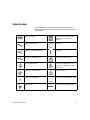
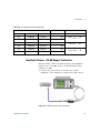
Agilent U2761A
USB Modular
Function/Arbitrary
Waveform Generator
Service Guide
Agilent Technologies
Notices
© Agilent Technologies, Inc., 2008–2013
Warranty
No part of this manual may be reproduced in
any form or by any means (including electronic storage and retrieval or translation
into a foreign language) without prior agreement and written consent from Agilent
Technologies, Inc. as governed by United
States and international copyright laws.
The material contained in this document is provided “as is,” and is subject to being changed, without notice,
in future editions. Further, to the maximum extent permitted by applicable
law, Agilent disclaims all warranties,
either express or implied, with regard
to this manual and any information
contained herein, including but not
limited to the implied warranties of
merchantability and fitness for a particular purpose. Agilent shall not be
liable for errors or for incidental or
consequential damages in connection with the furnishing, use, or performance of this document or of any
information contained herein. Should
Agilent and the user have a separate
written agreement with warranty
terms covering the material in this
document that conflict with these
terms, the warranty terms in the separate agreement shall control.
Manual Part Number
U2761-90010
Edition
Seventh Edition, August 2, 2013
Agilent Technologies, Inc.
5301 Stevens Creek Blvd.
Santa Clara, CA 95052 USA
Trademark Acknowledgements
Pentium is a U.S. registered trademark of
Intel Corporation.
Microsoft, Visual Studio, Windows, and MS
Windows are trademarks of Microsoft Corporation in the United States and/or other
countries.
Technology Licenses
The hardware and/or software described in
this document are furnished under a license
and may be used or copied only in accordance with the terms of such license.
Restricted Rights Legend
U.S. Government Restricted Rights. Software and technical data rights granted to
the federal government include only those
rights customarily provided to end user customers. Agilent provides this customary
commercial license in Software and technical data pursuant to FAR 12.211 (Technical
Data) and 12.212 (Computer Software) and,
for the Department of Defense, DFARS
252.227-7015 (Technical Data - Commercial
Items) and DFARS 227.7202-3 (Rights in
Commercial Computer Software or Computer Software Documentation).
ii
Safety Notices
CAUTION
A CAUTION notice denotes a hazard. It calls attention to an operating procedure, practice, or the like
that, if not correctly performed or
adhered to, could result in damage
to the product or loss of important
data. Do not proceed beyond a
CAUTION notice until the indicated
conditions are fully understood and
met.
WA R N I N G
A WARNING notice denotes a
hazard. It calls attention to an
operating procedure, practice, or
the like that, if not correctly performed or adhered to, could result
in personal injury or death. Do not
proceed beyond a WARNING
notice until the indicated conditions are fully understood and
met.
U2761A Service Guide
Safety Symbols
The following symbols on the instrument and in the documentation
indicate precautions which must be taken to maintain safe operation of
the instrument.
Direct current (DC)
Equipment protected throughout by
double insulation or reinforced
insulation
Alternating current (AC)
Off (supply)
Both direct and alternating current
On (supply)
Three-phase alternating current
Caution, risk of eletric shock
Earth (ground) terminal
Caution, risk of danger (refer to this
manual for specific Warning or Caution
information)
Protective conductor terminal
Caution, hot surface
Frame or chassis terminal
Out position of a bi-stable push control
Equipotentiality
In position of a bi-stable push control
U2761A Service Guide
iii
General Safety Information
The following general safety precautions must be observed during all
phases of operation of this instrument. Failure to comply with these
precautions or with specific warnings elsewhere in this manual violates
safety standards of design, manufacture and intended use of the
instrument. Agilent Technologies Inc. assumes no liability for the
customer’s failure to comply with these requirements.
iv
WA R N I N G
• Do not operate the product in an explosive atmosphere or in the
presence of flammable gases or fumes.
• Do not use the equipment if it does not operate properly. Have the
equipment inspected by qualified service personnal.
CAUTION
• Observe all markings on the instrument before connecting any wiring to
the instrument.
• Use the device with the cables provided.
• Repair or service that is not covered in this manual should only be
performed by qualified personnels.
U2761A Service Guide
Environment Conditions
This instrument is designed for indoor use and in the area with low
condensation. The table below shows the general environmental
requirements for this instrument.
CAUTION
Requirements
Operating temperature
0 °C to 50 °C
Operating humidity
20 to 85% RH noncondensing
Storage temperature
–20 °C to 70 °C
Storage humidity
5 to 90% RH noncondensing
The U2761A USB modular function/arbitrary waveform generator
complies with the following safety and EMC requirements.
•
•
•
•
•
•
U2761A Service Guide
Environment conditions
IEC 61010-1:2001/EN61010-1:2001 (2nd Edition)
Canada: CAN/CSA-C22.2 No. 61010-1-04
IEC 61326-2002/EN 61326:1997+A1:1998+A2:2001+A3:2003
Canada: ICES-001:2004
Australia/New Zealand: AS/NZS CISPR11:2004
USA: ANSI/UL 61010-1:2004
v
Regulatory Markings
The CE mark is a registered trademark
of the European Community.This CE
mark shows that the product complies
with all the relevant European Legal
Directives.
The C-tick mark is a registered
trademark of the Spectrum
Management Agency of Australia.
This signifies compliance with
the Australia EMC Framework
regulations under the terms of the
Radio Communication Act of 1992.
ICES/NMB-001 indicates that this
ISM device complies with Canadian
ICES-001.
Cet appareil ISM est confomre a la
norme NMB-001 du Canada.
This instrument complies with the
WEEE Directive (2002/96/EC)
marking requirement. This affixed
product label indicates that you must
not discard this electrical/electronic
product in domestic household waste.
The CSA mark is a registered
trademark of the Canadian Standards
Association.
vi
U2761A Service Guide
Waste Electrical and Electronic Equipment (WEEE) Directive
2002/96/EC
This instrument complies with the WEEE Directive (2002/96/EC) marking
requirement. This affixed product label indicates that you must not discard
this electrical/electronic product in domestic household waste.
Product Category:
With reference to the equipment types in the WEEE directive Annex 1, this
instrument is classified as a “Monitoring and Control Instrument” product.
The affixed product label is shown as below:
Do not dispose in domestic household waste
To return this unwanted instrument, contact your nearest Agilent office, or
visit:
www.agilent.com/environment/product
for more information.
U2761A Service Guide
vii
In This Guide…
1
Characteristics and Specifications
The characteristics and specifications of the U2761A are listed in this
chapter.
2
Getting Started
In this chapter, you will learn about the the self-test procedure for the
U2761A. The information for returning the U2761A for calibration or
servicing is also provided.
3
Calibration
This chapter describes the performance verification and calibration
procedures for the U2761A.
4
Disassembly
The disassembly procedure for the U2761A is discussed in this chapter.
5
Troubleshooting
This chapter provides the general troubleshooting tips for the U2761A.
viii
U2761A Service Guide
Declaration of Conformity (DoC)
The Declaration of Conformity (DoC) for this instrument is
available on the Web site. You can search the DoC by its
product model or description.
http://regulations.corporate.agilent.com/DoC/search.htm
NOTE
U2761A Service Guide
If you are unable to search for the respective DoC, please contact your
local Agilent representative.
ix
THIS PAGE HAS BEEN INTENTIONALLY LEFT BLANK.
x
U2761A Service Guide
Contents
1
Characteristics and Specifications 1
Product Characteristics 2
Product Specifications and Characteristics 4
2
Getting Started 9
Introduction 10
Self-Test 10
Agilent Technologies Calibration Services 12
Calibration Interval 12
Types of Service Available 12
Extended Service Contracts 12
Obtaining Repair Service (Worldwide) 13
Repackaging for Shipment 14
Cleaning 14
3
Calibration 15
Introduction 16
Recommended Test Equipment 16
Test Consideration 17
Performance Verification Procedures 18
Internal Timebase Verification 18
Output Impedance Verification 19
AC Amplitude (High Impedance) Verification 21
Amplitude Flatness (–20 dB Range) Verification 23
Amplitude Flatness (0 dB Range) Verification 26
Amplitude Flatness (+20 dB Range) Verification 28
U2761A Service Guide
xi
Calibration Procedure 30
Internal Timebase Adjustment 31
Output Impedance Adjustment 32
DC Offset (High Impedance) Adjustment 33
AC Amplitude (High Impedance) Adjustment 34
Amplitude Flatness (–20 dB Range) Adjustment 37
Amplitude Flatness (0 dB Range) Adjustment 39
Amplitude Flatness (+20 dB Range) Adjustment 41
4
Disassembly 43
General Disassembly 44
Disassembly Instructions 44
Reassembly Instructions 46
Replacement Parts 46
5
Troubleshooting 49
Troubleshooting 50
Index 51
xii
U2761A Service Guide
List of Figures
Figure 3-1
Figure 3-3
Figure 3-4
Figure 3-5
U2761A Service Guide
U2761A to frequency counter connection 18
U2761A to DMM connection 20
U2761A to power meter connection 23
U2761A to DMM four-wire connection 32
xiii
List of Tables
Table 3-1
Table 3-2
Table 3-4
Table 3-5
Table 3-6
Table 3-7
Table 3-8
Table 3-9
Table 3-10
Table 3-11
Table 3-12
Table 3-13
Table 3-14
Table 3-15
Table 3-16
Table 3-17
Table 3-18
Table 3-19
xiv
Recommended test equipment 16
Configuration for timebase verification 19
Configuration for DC offset verification 21
Configuration for AC amplitude verification 22
AC amplitude verification worksheet 23
Configuration for AC amplitude flatness (–20 dB range)
verification 25
Configuration for AC amplitude flatness (0 dB range)
verification 27
Configuration for AC amplitude flatness (+20 dB range)
verification 29
Timebase adjustment configuration 31
Output impedance adjustment configuration 32
DC offset (High Impedance) adjustment
configuration 33
Configuration for Sine wave AC amplitude
adjustment 34
Sine wave flatness worksheet 35
Configuration for 50% ramp AC amplitude
adjustment 35
Configuration for 50% pulse AC amplitude
adjustment 36
Configuration for AC amplitude flatness (–20 dB range)
adjustment 38
Configuration for AC amplitude flatness ( 0 dB range)
adjustment 40
Configuration for AC amplitude flatness (+20 dB range)
adjustment 42
U2761A Service Guide
Agilent U2761A USB Modular Function/Arbitrary Waveform Generator
Service Guide
1
Characteristics and Specifications
Product Characteristics 2
Product Specifications and Characteristics 4
This chapter specifies the characteristics, environmental
conditions, and specifications of the U2761A.
Agilent Technologies
1
1
Characteristics and Specifications
Product Characteristics
REMOTE INTERFACE
• Hi-Speed USB 2.0
• USBTMC 488.2 Class device [1]
POWER CONSUMPTION
• +12 VDC, 1.2 A
• Isolated ELV power source
OPERATING ENVIRONMENT
• Operating temperature from 0 °C to 50 °C
• Operating humidity at 20% to 85% RH (noncondensing)
• Altitude up to 2000 meters
• Pollution Degree 2
• For indoor use only
STORAGE COMPLIANCE
• Storage temperature from –20 °C to 70 °C
• Storage humidity at 5% to 90% RH (noncondensing)
SAFETY COMPLIANCE
Certified with:
• IEC 61010-1:2001/EN61010-1:2001 (2nd Edition)
• Canada: CAN/CSA-C22.2 No. 61010-1-04
• USA: ANSI/UL 61010-1:2004
EMC COMPLIANCE
• IEC 61326-2002/EN 61326:1997+A1:1998+A2:2001+A3:2003
• Canada: ICES-001:2004
• Australia/New Zealand: AS/NZS CISPR11:2004
SHOCK & VIBRATION
Tested to IEC/EN 60068-2
IO CONNECTOR
BNC connector
DIMENSION (W×D×H)
• 117.00 mm × 180.00 mm × 41.00 mm (with bumpers)
• 105.00 mm × 175.00 mm × 25.00 mm (without bumpers)
WEIGHT
• 528 g (with bumpers)
• 476 g (without bumpers)
WARRANTY
3 years
2
U2761A Service Guide
Characteristics and Specifications
1
[1]
Requires a direct USB connection to the PC so the appropriate driver can be
installed in the USB modular instrument or USB DAQ module.
U2761A Service Guide
3
1
Characteristics and Specifications
Product Specifications and Characteristics
WAVEFORMS
Standard
Sine, Square, Ramp, Triangle, Pulse, DC
Built-in arbitrary
Exponential Rise, Exponential Fall, Negative Ramp
WAVEFORM CHARACTERISTICS
Sine
Frequency range
1 μHz to 20 MHz (1 μHz resolution)
Amplitude flatness 1
≤ 100 kHz
(relative to 1 kHz)
100 kHz to 1 MHz
0.35 dB
1 MHz to 20 MHz
0.7 dB
Frequency range
< 1 Vpp
≥1 Vpp
DC to 20 kHz
–70 dBc
–60 dBc
20 kHz to 100 kHz
–65 dBc
–60 dBc
100 kHz to 1 MHz
–50 dBc
–45 dBc
–35 dBc
Harmonic distortion 2
0.2 dB
1 MHz to 20 MHz
–40 dBc
Total harmonic distortion 2
DC to 20 kHz
0.10%
Spurious (Nonharmonic) output 3
DC to 1 MHz
–65 dBc
1 MHz to 20 MHz
–65 dBc + 6 dB/octave
Phase noise (10 kHz offset)
–115 dBc/Hz (Typical)
Square
4
Frequency range
1 μHz to 20 MHz (1 μHz resolution)
Rise/fall time
< 18 ns, 10 to 90% terminated load (50 Ω)
Overshoot
< 2%
Variable duty cycle
20% to 80% (up to 10 MHz)
40% to 60% (up to 20 MHz)
Asymmetry (@ 50% duty)
1% of period + 5 ns
Jitter (RMS)
> 50 kHz = 1 ns + 100 ppm of period
≤ 50 kHz = 10 ns + 100 ppm of period
U2761A Service Guide
Characteristics and Specifications
1
Ramp, Triangle
Frequency range
1 μHz to 200 kHz (1 μHz resolution)
Linearity
< 0.2% of peak output
Programmable symmetry
0% to 100%
Pulse
Frequency range
500 μHz to 5 MHz (1 μHz resolution)
Pulse width (period ≤ 10 s)
40 ns minimum, 10 ns resolution
Overshoot
< 3%
Jitter (RMS)
300 ps + 0.1 ppm of period
Arbitrary
Memory depth
1 μHz to 200 kHz (1 μHz resolution)
1 μHz to 2 MHz (1 μHz resolution) - Option U2010A
64 kSa
Amplitude resolution
14 bits/sample (including sign)
Sampling rate
50 MSa/s
Minimum rise/fall time
36 ns, typical
Linearity
< 0.2% of peak output
Settling time
< 250 ns to 0.5% of final value
Jitter (RMS)
10 ns + 30 ppm
Frequency range
U2761A Service Guide
5
1
Characteristics and Specifications
COMMON CHARACTERISTICS
Amplitude
Range
40 mVpp to 5 Vpp (Into 50 Ω load)
80 mVpp to 10 Vpp (Into open circuit)
Accuracy 1 (across 50 Ω load at 1 kHz)
±1% of setting ±5 mV (±10 mV @ Hi-Z)
Units
Vpp, Vrms, dBm
Resolution
4 digits
DC offset
Range (peak AC + DC)
±2.5 V (Into 50 Ω load)
±5 V (Into open circuit)
Accuracy 1 (across 50 Ω load)
±2% of offset setting ±1% of amplitude setting ±5 mV
(±10 mV @ Hi-Z)
Amplitude limit
Amplitude + Offset limit to within ±2.5 V range across 50 Ω load or
±5 V across open circuit
Main output
Impedance
50 Ω ± 0.5 Ω load
Isolation
At least 42 Vpk to earth
Protection
Short-circuit protected, overload automatically disables main output
Internal frequency reference
Accuracy 4
±8 ppm in 1 year
External frequency reference
Input lock range
10 MHz ± 170 Hz
Input amplitude level
500 mVpp to 5 Vpp
Impedance
50 Ω AC coupled
Lock time
<2s
Output frequency
10 MHz
Output amplitude level
632 mVpp, typical
Impedance
Return loss 10 dB typical at 10 MHz
Phase offset
6
Range
+360 ° to –360 °
Resolution
0.01 °
Accuracy
20 ns
U2761A Service Guide
Characteristics and Specifications
1
MODULATION
AM
Carrier waveforms
Sine, Square, Ramp, Arbitrary
Source
Internal
Internal modulation
Sine, Square, Ramp, Arbitrary (2 mHz to 20 kHz)
Depth
0.0% to 100.0%
FM
Carrier waveforms
Sine, Square, Ramp, Arbitrary
Source
Internal
Internal modulation
Sine, Square, Ramp, Arbitrary (2 mHz to 20 kHz)
Deviation
1 Hz to 500 kHz
PM
Carrier waveforms
Sine, Square, Ramp, Arbitrary
Source
Internal
Internal modulation
Sine, Square, Ramp, Arbitrary (2 mHz to 20 kHz)
Deviation
0.0 to 360.0 °
FSK
Carrier waveforms
Sine, Square, Ramp, Arbitrary
Source
Internal
Internal modulation
50% duty cycle square (2 mHz to 100 kHz)
PSK
Carrier waveforms
Sine, Square, Ramp, Arbitrary
Source
Internal
Internal modulation
50% duty cycle square (2 mHz to 100 kHz)
Deviation
0.0 to 360.0 °
ASK
Carrier waveforms
Sine, Square, Ramp, Arbitrary
Source
Internal
Internal modulation
50% duty cycle square (2 mHz to 100 kHz)
U2761A Service Guide
7
1
Characteristics and Specifications
SWEEP CHARACTERISTICS
Waveforms
Sine, Square, Ramp, Arbitrary
Type
Linear or Logarithmic
Direction
Up or Down
Sweep time
1 ms to 500 s
Trigger
Single, External, or Internal
TRIGGER CHARACTERISTICS
Trigger input
Input level
TTL compatible
Slope
Rising or Falling, Selectable
Pulse width
> 100 ns
Input impedance
> 10 kΩ, DC coupled
Latency
< 500 ns
Jitter (RMS)
6 ns (3.5 ns for Pulse)
Trigger output
Input level
TTL compatible into ≥1 kΩ
Pulse width
> 400 ns
Output impedance
50 Ω, typical
Fanout
4 TTL
Rise time
≤20 ns
1 Add 1/10th of output amplitude and offset specification per °C for
operation outside the range of 18 °C to 28 °C.
2 DC offset set to 0 V.
3 Spurious output at low amplitude is –70 dBm, typical.
4 Add 1 ppm/°C (average) for operation outside the range of 18 °C to
28 °C.
8
U2761A Service Guide
Agilent U2761A USB Modular Function/Arbitrary Waveform Generator
Service Guide
2
Getting Started
Introduction 10
Self-Test 10
Agilent Technologies Calibration Services 12
Calibration Interval 12
Types of Service Available 12
Extended Service Contracts 12
Obtaining Repair Service (Worldwide) 13
Repackaging for Shipment 14
Cleaning 14
This chapter provides the self-test procedure for the U2761A
USB modular function generator. It also provides the
information for returning your U2761A to Agilent for
calibration or servicing.
If you have a defective module, you can return it to Agilent
for repair or replacement.
Agilent Technologies
9
2
Calibration
Introduction
Self-Test
A brief power-on self-test occurs automatically whenever the
U2761A is turned on. This limited test assures that the
instrument is capable of operation. To perform a complete
self-test, send the following SCPI command to the U2761A.
*TST?
The U2761A will automatically perform the complete self-test
procedure when the SCPI command is sent. The self-test will
be completed in a few seconds.
• If the self-test is successful, a zero (0) is returned.
• If the self-test fails, an error number is returned.
Agilent Measurement Manager
To start the self-test procedure using the Agilent
Measurement Manager, perform the following test.
1 Click Tools > Self-Test.
10
U2761A Service Guide
Calibration
2
2 Click Start on the Self-Test form.
3 Click OK to continue when the message box appears.
4 Wait for a few minutes for the self-test to complete.
5 The result is displayed on the form once the self-test has
completed.
U2761A Service Guide
11
2
Calibration
Agilent Technologies Calibration Services
When your U2761A is due for calibration, contact your local
Agilent Service Center for a low-cost recalibration. The
U2761A is supported on automated calibration systems,
which allows Agilent to provide this service at a competitive
price.
Calibration Interval
The U2761A should be verified and calibrated on a regular
interval based on the measurement accuracy requirements of
your application. A one-year interval is adequate for most
applications. Accuracy specifications are warranted only if
adjustments are made at regular verification and calibration
intervals.
Types of Service Available
If your U2761A fails during the warranty period, Agilent will
repair or replace it under the terms of your warranty. After
your warranty expires, Agilent offers repair services at
competitive prices.
Extended Service Contracts
Most Agilent products are provided with optional service
contracts that extend the coverage period after the standard
warranty expires. If you have this service contract and your
U2761A happens to fail during the coverage period, Agilent
will repair or replace it according to the contract.
12
U2761A Service Guide
Calibration
2
Obtaining Repair Service (Worldwide)
To obtain service for your U2761A (in-warranty, under
service contract, or post-warranty), contact your nearest
Agilent Service Center. They will arrange to have your unit
repaired or replaced, and are able to provide warranty or
repair cost information where applicable.
To obtain warranty, service, or technical support information
you can contact Agilent at one of the following telephone
numbers.
In the United States: 800 829 4444
In Europe: 31 20 547 2111
In Japan: (81) 426 56 7832
You can also use our Web link for the information on
contacting Agilent worldwide:
www.agilent.com/find/assist
Or contact your Agilent representative.
Before shipping your U2761A, ensure that you acquire
shipping instructions, including the components to be
shipped, from the Agilent Service Center. Agilent
recommends that you retain the original shipping carton for
use in such shipments.
U2761A Service Guide
13
2
Calibration
Repackaging for Shipment
If the U2761A is to be shipped to Agilent for service or
repair, make sure that you do the following.
• Attach a tag to the U2761A identifying the owner and
indicating the required service or repair. Include the
model number and full serial number.
• Place the U2761A in its original container with
appropriate packaging material for shipping.
• Secure the container with strong tape or metal bands.
• If the original shipping container is not available, place
your U2761A in a container with at least four inches of
compressible packaging material around all sides of the
U2761A. Use static-free packaging materials to avoid
additional damage to your U2761A.
NOTE
Agilent suggests that you always insure your shipments.
Cleaning
Clean the outer area of the U2761A with a soft, lint-free,
and slightly dampened cloth. Do not use detergent.
Disassembly is not required for cleaning.
14
U2761A Service Guide
Agilent U2761A USB Modular Function/Arbitrary Waveform Generator
Service Guide
3
Calibration
Introduction 16
Recommended Test Equipment 16
Test Consideration 17
Performance Verification Procedures 18
Internal Timebase Verification 18
Output Impedance Verification 19
DC Offset (High Impedance) Verification 20
AC Amplitude (High Impedance) Verification 21
Amplitude Flatness (–20 dB Range) Verification 23
Amplitude Flatness (0 dB Range) Verification 26
Amplitude Flatness (+20 dB Range) Verification 28
Calibration Procedure 30
Internal Timebase Adjustment 31
Output Impedance Adjustment 32
DC Offset (High Impedance) Adjustment 33
AC Amplitude (High Impedance) Adjustment 34
Amplitude Flatness (–20 dB Range) Adjustment 37
Amplitude Flatness (0 dB Range) Adjustment 39
Amplitude Flatness (+20 dB Range) Adjustment 41
The verification and calibration procedures described in this
chapter verify that the U2761A is operating normally and is
within its warranted specifications.
Agilent Technologies
15
3
Calibration
Introduction
If the U2761A fails any of the tests or if any abnormal test
results are obtained, return the unit to the Agilent Service
Center for readjustment.
Recommended Test Equipment
The recommended test equipment for the verification and
calibration procedures are listed in the table below.
Table 3-1 Recommended test equipment
Instrument
Digital
multimeter
(DMM)
Minimum requirement
AC volts
• True rms
• AC coupled
• Accuracy: ±0.02% to 1 MHz
DC volts
Recommended model
Agilent 3458A
Purpose
Measures voltage. Used in
multiple procedures
Agilent E4418B
Measures voltage. Used in
multiple procedures
Agilent 8482A
Agilent 53131A Opt 010
Measure voltages. Used in
multiple procedures
Checks timebase parameter
Agilent DS08064A
Checks output signal
Agilent E4443A
Checks output signal
–
Signal interconnected
• Accuracy: 50 ppm
• Resolution: 100 μV
Resistance
Power meter
Power sensor
Frequency
counter
Oscilloscope
Spectrum
analyzer
Cable and
adaptor
16
•
•
•
•
•
•
•
• 4-wire measurement
• Offset compensated
• Accuracy: ±0.1 Ω
100 kHz to 100 MHz
1 μW to 100 mW (–30 dBm to +20 dBm)
Accuracy: 0.02 dB
Resolution: 0.01 dB
100 kHz to 100 MHz
1 μW to 100 mW (–30 dBm to +20 dBm)
Accuracy: 0.1 ppm
•
•
•
•
•
•
•
•
•
•
•
500 MHz
2 GSa/s
50 Ω input termination
10 kHz to 1 GHz
Average Continuous Power: +25 dBm
Amplitude Accuracy: ±0.5 dB
Input Impedance: 50 Ω
50 Ω BNC (male to male) cable
BNC (female) to dual banana
BNC (female) to N type (male)
BNC (female) to N type (female)
U2761A Service Guide
Calibration
3
Test Consideration
For optimum performance, all procedures should comply
with the following recommendations.
• Ensure that the calibration ambient temperature is stable
and between 23 °C ± 3 °C.
• The ambient relative humidity must be less than 80%.
• Allow a one-hour warm-up period before verification or
adjustment.
• Keep the measurement cables as short as possible and
consistent with the impedance requirement.
• Use RG-58 or equivalent 50 Ω cable.
U2761A Service Guide
17
3
Calibration
Performance Verification Procedures
It is recommended to carry out performance verification
tests when you first receive the U2761A. The performance
verification test results should be compared to the
specifications of the U2761A. You should repeat the
performance verification tests at every calibration interval.
If the U2761A fails the performance verification tests,
adjustment or repair is required. Some of the specifications
are adjustable, or otherwise replacement of parts may be
required.
Internal Timebase Verification
This test verifies the accuracy of the output frequency of the
U2761A. All output frequencies are derived from a single
generated frequency.
1 Connect the U2761A to a frequency counter as shown in
the following figure. The input termination of the
frequency counter must be 50 Ω.
Figure 3-1 U2761A to frequency counter connection
18
U2761A Service Guide
Calibration
3
2 Set the U2761A to the output shown in the table below
and measure the output frequency. Make sure that the
U2761A output is enabled.
Table 3-2 Configuration for timebase verification
U2761A
Measurement
Function
Amplitude
Frequency
Nominal
Error1
Sine
1.00 Vpp
10.0000 MHz
10.0000 MHz
±80 Hz
1 Based upon ±8 ppm for one year.
3 Compare the measured frequency with the test limit
shown in Table 3- 2.
Output Impedance Verification
The U2761A stores the calibration constant for the output
impedance. The output impedance measurement is necessary
to calculate the correct output amplitude when the load
impedance is not at High- Z termination. The output
impedance is measured at three different output paths.
1 Set the DMM to measure offset-compensated, four-wire
ohms. Set the DMM to use 100 NPLC integration. Connect
the DMM to the U2761A as shown in the figure below.
Figure 3-2 U2761A to DMM four-wire connection
U2761A Service Guide
19
3
Calibration
2 Use the DMM to make the resistance measurement at the
output terminal for each setup shown in the table below.
The expected measured value is approximately 50 Ω..
3 This procedure will require you to unsecure the
instrument for calibration. See “Calibration Procedure” on
page 30 for more information on how to unsecure the
instrument for calibration. The calibration constant is not
stored to the U2761A after completing the setup.
Table 3-3 Output impedance verification configuration
U2761A
CalSet
5
6
7
DMM
Output path
–20 dB
0 dB
+20 dB
Lower margin
49.5 Ω
49.5 Ω
49.5 Ω
Measurement
Ω
Ω
Ω
Upper margin
50.5 Ω
50.5 Ω
50.5 Ω
4 Exit the Calibration Mode.
DC Offset (High Impedance) Verification
This procedure verifies the accuracy of the DC offset with
high impedance load (DMM input impedance of 10 MΩ).
1 Set the DMM to measure DC voltage. Connect the DMM to
the U2761A as shown in the following figure. The DMM
input impedance must be set to 10 MΩ.
Figure 3-3 U2761A to DMM connection
20
U2761A Service Guide
Calibration
3
2 Set the U2761A based on the following.
• Load impedance: High-Z
• Function: DC
3 Set the U2761A to each output listed in the table below.
Table 3-4 Configuration for DC offset verification
U2761A
Measurement
DC offset
Nominal
Error1
–5.000 VDC
–5.000 VDC
±0.11 VDC
–2.500 VDC
–2.500 VDC
±0.06 VDC
0.000 VDC
0.000 VDC
±0.01 VDC
+2.500 VDC
+2.500 VDC
±0.06 VDC
+5.000 VDC
+5.000 VDC
±0.11 VDC
1 Based upon ±2% of offset setting ±10 mV (High-Z).
4 Compare the measured voltages with the test limits shown
in Table 3- 4.
AC Amplitude (High Impedance) Verification
This procedure verifies the accuracy of the AC output
amplitude at frequencies of 1 kHz and 100 kHz, and
establishes reference measurement for the higher frequency
flatness verification procedures.
1 Set the DMM to measure AC voltage. Connect the DMM to
the U2761A as shown in Figure 3- 3.
2 Set the U2761A based on the following.
• Load impedance: High-Z
• Offset: 0 V
U2761A Service Guide
21
3
Calibration
3 Set the U2761A to each output listed in the table below.
Table 3-5 Configuration for AC amplitude verification
U2761A
Measurement
Function
Frequency
Amplitude
Nominal
Error1
Sine
1.00000 kHz
70 mVrms
70 mVrms
±4.236 mVrms
Sine
100.000 kHz
70 mVrms
70 mVrms
±5.146 mVrms
Sine
1.00000 kHz
700 mVrms
700 mVrms
±10.54 mVrms
Sine
100.000 kHz
700 mVrms
700 mVrms
±19.64 mVrms
Sine
1.00000 kHz
3.500 Vrms
3.500 Vrms
±38.54 mVrms
Sine
100.000 kHz
3.500 Vrms
3.500 Vrms
±84.04 mVrms
50% Ramp
1.00000 kHz
50 mVrms
50 mVrms
±3.387 Vrms
50% Ramp
1.00000 kHz
500 mVrms
500 mVrms
±7.887 mVrms
50% Ramp
1.00000 kHz
2.500 Vrms
2.500 Vrms
±27.89 mVrms
50% Square
1.00000 kHz
90 mVrms
90 mVrms
±5.900 mVrms
50% Square
1.00000 kHz
900 mVrms
900 mVrms
±14.00 mVrms
50% Square
1.00000 kHz
4.500 VRms
4.500 Vrms
±50.00 mVrms
1 1 kHz: Based upon ±1% of setting ±5 mVpp (50 Ω) converted to Vrms for
High-Z.
100 kHz: Based upon ±0.2 dB (2.3%) of setting ±5 mVpp (50 Ω) converted to
Vrms for High-Z.
4 Compare the measured voltage with the test limits shown
in above table, and fill in Table 3- 6 using the following
equation.
Offset = 20 × log ⎛ V rms 100 k H z⎞
⎝ V rms 1 k H z ⎠
22
U2761A Service Guide
Calibration
3
Table 3-6 AC amplitude verification worksheet
U2761A
DMM
Calculation
Measurement
Offset
Function
Frequency
Amplitude
Sine
1.00000 kHz
70 mVrms
Vrms
Sine
100.000 kHz
70 mVrms
Vrms
Sine
1.00000 kHz
700 mVrms
Vrms
Sine
100.000 kHz
700 mVrms
Vrms
Sine
1.00000 kHz
3.500 Vrms
Vrms
Sine
100.000 kHz
3.500 Vrms
Vrms
Offset –20 dB = ___ dB
Offset 0 dB = ___ dB
Offset + 20 dB = ___ dB
Amplitude Flatness (–20 dB Range) Verification
This procedure verifies the high frequency AC amplitude
flatness above 100 kHz on the –20 dB attenuator range
relative to 1 kHz.
1 Connect the power meter to measure the output
amplitude of the U2761A as shown in the figure below.
Figure 3-4 U2761A to power meter connection
U2761A Service Guide
23
3
Calibration
2 Set the U2761A based on the following.
• Load impedance: 50 Ω
• Function: Sine wave
• Frequency: 100 kHz
• Amplitude: 35 mVrms (–16.108 dBm)
3 Set the power meter Filter Mode to Manual and set Average
Length to 500 to improve measurement stability. Allow a
minimum of 30 s between the time of setting the U2761A
and collecting the measurement reading.
4 On the power meter, use the Relative Power function to set
the current reading as the reference value. This allows
you to compare future measurement result in dB.
5 Set the power meter Offset to the Offset–20dB value
previously calculated in Table 3- 6. The power meter will
directly read the flatness error specification to
1 kHz.
6 Set the U2761A to each output listed in Table 3- 7.
Measure the output amplitude using the power meter (the
relative measurement in dB).
7 Compare the measured output with the test limits shown
in Table 3- 7.
24
U2761A Service Guide
Calibration
3
Table 3-7 Configuration for AC amplitude flatness (–20 dB range)
verification
U2761A
U2761A Service Guide
Measurement
Function
Amplitude
Frequency
Nominal
Error
Sine
35 mVrms
100.000 kHz
0.000 dB
±0.2 dB
Sine
35 mVrms
160.000 kHz
0.000 dB
±0.35 dB
Sine
35 mVrms
250.000 kHz
0.000 dB
±0.35 dB
Sine
35 mVrms
400.000 kHz
0.000 dB
±0.35 dB
Sine
35 mVrms
630.000 kHz
0.000 dB
±0.35 dB
Sine
35 mVrms
1.00000 MHz
0.000 dB
±0.35 dB
Sine
35 mVrms
1.60000 MHz
0.000 dB
±0.7 dB
Sine
35 mVrms
2.50000 MHz
0.000 dB
±0.7 dB
Sine
35 mVrms
4.00000 MHz
0.000 dB
±0.7 dB
Sine
35 mVrms
6.30000 MHz
0.000 dB
±0.7 dB
Sine
35 mVrms
10.0000 MHz
0.000 dB
±0.7 dB
Sine
35 mVrms
11.5000 MHz
0.000 dB
±0.7 dB
Sine
35 mVrms
13.2000 MHz
0.000 dB
±0.7 dB
Sine
35 mVrms
15.2000 MHz
0.000 dB
±0.7 dB
Sine
35 mVrms
17.4000 MHz
0.000 dB
±0.7 dB
Sine
35 mVrms
20.0000 MHz
0.000 dB
±0.7 dB
25
3
Calibration
Amplitude Flatness (0 dB Range) Verification
This procedure verifies the high frequency AC amplitude
flatness above 100 kHz on the 0 dB range relative to 1 kHz.
1 Connect the power meter to measure the output
amplitude of the U2761A as shown in Figure 3- 4.
2 Set the U2761A based on the following.
• Load impedance: 50 Ω
• Function: Sine wave
• Frequency: 100 kHz
• Amplitude: 350 mVrms (+3.892 dBm)
3 Set the power meter Filter Mode to Auto if you have
previously set it to Manual.
4 On the power meter, use the Relative Power function to set
the current reading as the reference value. This will allow
you to compare future measurement result in dB.
5 Set the power meter Offset to Offset0dB value previously
calculated in Table 3- 6. The power meter will directly
read the flatness error specification relative to 1 kHz.
6 Set the U2761A to each output listed in the Table 3- 8.
Measure the output amplitude using the power meter (the
relative measurement in dB).
7 Compare the measured output with the test limits shown
in the Table 3- 8.
26
U2761A Service Guide
Calibration
3
Table 3-8 Configuration for AC amplitude flatness (0 dB range)
verification
U2761A
U2761A Service Guide
Measurement
Function
Amplitude
Frequency
Nominal
Error
Sine
350 mVrms
100.000 kHz
0.000 dB
±0.2 dB
Sine
350 mVrms
160.000 kHz
0.000 dB
±0.35 dB
Sine
350 mVrms
250.000 kHz
0.000 dB
±0.35 dB
Sine
350 mVrms
400.000 kHz
0.000 dB
±0.35 dB
Sine
350 mVrms
630.000 kHz
0.000 dB
±0.35 dB
Sine
350 mVrms
1.00000 MHz
0.000 dB
±0.35 dB
Sine
350 mVrms
1.60000 MHz
0.000 dB
±0.7 dB
Sine
350 mVrms
2.50000 MHz
0.000 dB
±0.7 dB
Sine
350 mVrms
4.00000 MHz
0.000 dB
±0.7 dB
Sine
350 mVrms
6.30000 MHz
0.000 dB
±0.7 dB
Sine
350 mVrms
10.0000 MHz
0.000 dB
±0.7 dB
Sine
350 mVrms
11.5000 MHz
0.000 dB
±0.7 dB
Sine
350 mVrms
13.2000 MHz
0.000 dB
±0.7 dB
Sine
350 mVrms
15.2000 MHz
0.000 dB
±0.7 dB
Sine
350 mVrms
17.4000 MHz
0.000 dB
±0.7 dB
Sine
350 mVrms
20.0000 MHz
0.000 dB
±0.7 dB
27
3
Calibration
Amplitude Flatness (+20 dB Range) Verification
This procedure verifies the high frequency AC amplitude
flatness above 100 kHz on the +20 dB amplifier range
relative to 1 kHz.
1 Connect the power meter and power sensor together to
measure the output amplitude of the U2761A as shown in
Figure 3- 4.
2 Set the U2761A based on the following.
• Load impedance: 50 Ω
• Function: Sine wave
• Frequency: 100 kHz
• Amplitude: 1.750 Vrms (+17.871 dBm)
3 Set the power meter Filter Mode to Auto if you have
previously set it to Manual.
4 On the power meter, use the Relative Power function to set
the current reading as the reference value. This will allow
you to compare future measurement result in dB.
5 Set the power meter Offset to Offset+20dB value previously
calculated in Table 3- 6. The power meter will directly
read the flatness error specification relative to 1 kHz.
6 Set the U2761A to each output listed in the Table 3- 9.
Measure the output amplitude using the power meter (the
relative measurement in dB).
7 Compare the measured output with the test limits shown
in the Table 3- 9.
28
U2761A Service Guide
Calibration
3
Table 3-9 Configuration for AC amplitude flatness (+20 dB range)
verification
U2761A
U2761A Service Guide
Measurement
Function
Amplitude
Frequency
Nominal
Error
Sine
1.750 Vrms
100.000 kHz
0.000 dB
±0.2 dB
Sine
1.750 Vrms
160.000 kHz
0.000 dB
±0.35 dB
Sine
1.750 Vrms
250.000 kHz
0.000 dB
±0.35 dB
Sine
1.750 Vrms
400.000 kHz
0.000 dB
±0.35 dB
Sine
1.750 Vrms
630.000 kHz
0.000 dB
±0.35 dB
Sine
1.750 Vrms
1.00000 MHz
0.000 dB
±0.35 dB
Sine
1.750 Vrms
1.60000 MHz
0.000 dB
±0.7 dB
Sine
1.750 Vrms
2.50000 MHz
0.000 dB
±0.7 dB
Sine
1.750 Vrms
4.00000 MHz
0.000 dB
±0.7 dB
Sine
1.750 Vrms
6.30000 MHz
0.000 dB
±0.7 dB
Sine
1.750 Vrms
10.0000 MHz
0.000 dB
±0.7 dB
Sine
1.750 Vrms
11.5000 MHz
0.000 dB
±0.7 dB
Sine
1.750 Vrms
13.2000 MHz
0.000 dB
±0.7 dB
Sine
1.750 Vrms
15.2000 MHz
0.000 dB
±0.7 dB
Sine
1.750 Vrms
17.4000 MHz
0.000 dB
±0.7 dB
Sine
1.750 Vrms
20.0000 MHz
0.000 dB
±0.7 dB
29
3
Calibration
Calibration Procedure
Calibration is necessary when the one-year calibration
interval has expired, or whenever the U2761A fails any
verification test. To enter the calibration mode, send the
following SCPI command to the U2761A.
CALibration:SECure:STATe OFF,U2761A
Once the calibration state is unsecured, the U2761A is now
in the calibration mode and setup is 0 by default. All the
calibration setup is predetermined and transparent to the
user. The user is free to perform a full calibration setup
from 1 to 115, or may choose to perform only a particular
group. To perform a particular calibration setup, send the
following SCPI command to U2761A.
CALibration:SETup<1|2|3|...|115>
The current calibration setup can be queried using the
following SCPI command when necessary.
CALibration:SETup?
The U2761A will output a predefined waveform at the output
terminal according to the setup number entered. Perform the
measurements as described in “Internal Timebase
Adjustment” on page 31 until “Amplitude Flatness (+20 dB
Range) Adjustment” on page 41, and enter the measured
values to the U2761A using the SCPI commands as follows.
CALibration:VALue <value>
The calibration value must be entered at the magnitude of
the units shown in the configuration tables accordingly. If
the user accidentally enters a wrong value, simply reenter a
correct value under the same calibration setup. Proceed to
the next calibration setup by entering a new setup number
once the calibration value is entered.
30
U2761A Service Guide
Calibration
3
Please note that the calibration constant will only be stored
after the user completes the subsequent calibration setup in
each group within a single calibration mode login. To exit
the calibration mode, send the following SCPI command to
the U2761A.
CALibration:SECure:STATe ON,U2761A
Internal Timebase Adjustment
The U2761A relies on a VCTCXO to generate the precision
clock to drive the DDS architecture. This procedure
determines the suitable control voltage for the VCTCXO to
output the correct frequency. This procedure implements a
three-time approach to obtain the best possible control
voltage.
1 Set the frequency counter to measure frequency. The
frequency counter resolution must be higher than 0.1 ppm
(eight digits or more).
2 Set the frequency counter input termination to 50 Ω. If
your frequency counter does not have a 50 Ω input
termination, you must provide an external termination.
3 Connect the frequency counter as shown in Figure 3- 1.
Use the frequency counter to measure the output
frequency for each setup shown in the table below.
4 Enter the measured value to the U2761A as described in
“Calibration Procedure” on page 30.
Table 3-10 Timebase adjustment configuration
U2761A
Frequency counter
Setup
Frequency
1
< 10 MHz
1 Vpp
9.999000 MHz
MHz
9.999800 MHz
2
> 10 MHz
1 Vpp
10.000200 MHz
MHz
10.001000 MHz
3
_ 10 MHz
1 Vpp
9.999900 MHz
MHz
10.000100 MHz
1
= 10 MHz
1 Vpp
9.999990 MHz
MHz
10.000010 MHz
4
Amplitude
Lower margin
Measurement
Upper margin
1 Calibration constant is stored after completing this setup.
U2761A Service Guide
31
3
Calibration
5 Proceed to output impedance adjustment or exit the
calibration mode when necessary.
Output Impedance Adjustment
The U2761A stores the calibration constant for output
impedance. The output impedance measurement is necessary
to calculate the correct output amplitude when the load
impedance is not at High-Z termination. The output
impedance is measured at three different output paths.
1 Set the DMM to measure offset-compensated, four-wire
ohms. Set the DMM to use 100 NPLC integration. Connect
the DMM to the U2761A as shown in the figure below.
Figure 3-5 U2761A to DMM four-wire connection
2 Use the DMM to make the resistance measurement at the
output terminal for each setup shown in the table below.
The expected measured value is approximately 50 Ω..
3 Make sure the Offset Compensation setting in the DMM is
switched on.
4 Enter the measured value to the U2761A as described in
“Calibration Procedure” on page 30.
Table 3-11 Output impedance adjustment configuration
U2761A
Setup
5
6
71
32
DMM
Output path
–20 dB
0 dB
+20 dB
Lower margin
49.5 Ω
49.5 Ω
49.5 Ω
Measurement
Ω
Ω
Ω
Upper margin
50.5 Ω
50.5 Ω
50.5 Ω
U2761A Service Guide
Calibration
3
1 Calibration constant is stored after completing this setup.
5 Proceed to DC offset adjustment or exit the calibration
mode when necessary.
DC Offset (High Impedance) Adjustment
The U2761A stores the calibration constant related to gain
and offset of the internal system DAC to control the offset
setting. This setting is used for both offset and DC outputs.
1 Set the DMM to measure DC voltage. Connect the DMM to
the U2761A as shown in Figure 3- 3. The DMM input
impedance should be set to 10 MΩ.
2 Use the DMM to perform the DC voltage measurement at
the output terminal for each setup shown in the table
below.
3 Enter the measured value to the U2761A as described in
“Calibration Procedure” on page 30.
Table 3-12 DC offset (High Impedance) adjustment configuration
U2761A
DMM
Setup
Amplifier
DC offset
Lower margin
Measurement
Upper margin
8
Off
+4.800 VDC
+4.608 VDC
VDC
+4.992 VDC
9
Off
–4.800 VDC
–4.992 VDC
VDC
–4.608 VDC
10
On
+2.600 VDC
+2.496 VDC
VDC
+2.704 VDC
11
On
+4.800 VDC
+4.608 VDC
VDC
+4.992 VDC
12
On
–2.600 VDC
–2.704 VDC
VDC
–2.496 VDC
131
On
–4.800 VDC
–4.992 VDC
VDC
–4.608 VDC
1 Calibration constant is stored after completing this setup.
U2761A Service Guide
33
3
Calibration
4 Proceed to AC amplitude (High Impedance) adjustment or
exit the calibration mode when necessary.
AC Amplitude (High Impedance) Adjustment
This procedure calculates the AC amplitude calibration
factor of three output paths for Sine wave, Ramp wave, and
Square wave individually.
1 Set the DMM to measure AC voltage. Connect the DMM to
the U2761A as shown in Figure 3- 3.
2 Use the DMM to perform AC voltage measurement at the
output terminal for each setup shown in the table below.
3 Enter the measured value to the U2761A as described in
“Calibration Procedure” on page 30.
Table 3-13 Configuration for Sine wave AC amplitude adjustment
U2761A
34
DMM
Setup
Function
Frequency
Amplitude
Lower margin
Measurement
Upper margin
14
Sine
1.00000 kHz
32 mVrms
30.4 mVrms
Vrms
33.6 mVrms
15
Sine
1.00000 kHz
60 mVrms
57.0 mVrms
Vrms
63.0 mVrms
16
Sine
100.000 kHz
60 mVms
57.0 mVrms
Vrms
63.0 mVrms
17
Sine
1.00000 kHz
80 mVrms
74.4 mVrms
Vrms
85.6 mVrms
18
Sine
1.00000 kHz
600 mVrms
558 mVrms
Vrms
642 mVrms
19
Sine
100.000 kHz
600 mVrms
558 mVrms
Vrms
642 mVrms
20
Sine
1.00000 kHz
800 mVrms
744 mVrms
Vrms
856 mVrms
21
Sine
1.00000 kHz
3.000 Vrms
2.79 Vrms
Vrms
3.21 Vrms
22
Sine
100.000 kHz
800 mVrms
744 mVrms
Vrms
856 mVrms
U2761A Service Guide
Calibration
3
4 Fill in the table below using the measurement results in
Table 3- 13.
Table 3-14
Sine wave flatness worksheet
Parameter
Calculation
Offset
Offset–20dB
V value ( 16 )
Offset = 20 × log -----------------------V value ( 15 )
dB
Offset0dB
V value ( 19 )
Offset = 20 × log -----------------------V value ( 18 )
dB
Offset+20dB
V value ( 22 )
Offset = 20 × log -----------------------V value ( 20 )
dB
5 Use the DMM to perform the AC voltage measurement at
the output terminal for each setup shown in the table
below.
6 Enter the measured value to the U2761A as described in
“Calibration Procedure” on page 30.
Table 3-15 Configuration for 50% ramp AC amplitude adjustment
U2761A
DMM
Setup
Function
Frequency
Amplitude
Lower margin
23
50% Ramp
1.00000 kHz
28 mVrms
26.6 mVrms
Vrms
29.4 mVrms
24
50% Ramp
1.00000 kHz
50 mVrms
47.5 mVrms
Vrms
52.5 mVrms
25
50% Ramp
1.00000 kHz
70 mVrms
65.1 mVrms
Vrms
74.9 mVrms
26
50% Ramp
1.00000 kHz
500 mVrms
465 mVrms
Vrms
535 mVrms
27
50% Ramp
1.00000 kHz
700 mVrms
651 mVrms
Vrms
749 mVrms
28
50% Ramp
1.00000 kHz
2.500 Vrms
2.325 Vrms
Vrms
2.675 Vrms
U2761A Service Guide
Measurement
Upper margin
35
3
Calibration
7 Use the DMM to perform the AC voltage measurement at
the output terminal for each setup shown in the table
below.
8 Enter the measured value to the U2761A as described in
“Calibration Procedure” on page 30.
Table 3-16 Configuration for 50% pulse AC amplitude adjustment
U2761A
DMM
Setup
Function
Period
Amplitude
Lower margin
Measurement
Upper margin
29
50% Pulse
1.00000 ms
44 mVrms
41.8 mVrms
Vrms
46.2 mVrms
30
50% Pulse
1.00000 ms
90 mVrms
85.5 mVrms
Vrms
94.5 mVrms
31
50% Pulse
1.00000 ms
110 mVrms
102.3 mVrms
Vrms
117.7 mVrms
32
50% Pulse
1.00000 ms
900 mVrms
837 mVrms
Vrms
963 mVrms
33
50% Pulse
1.00000 ms
1.100 Vrms
1.023 Vrms
Vrms
1.177 Vrms
341
50% Pulse
1.00000 ms
4.500 Vrms
4.185 Vrms
Vrms
4.815 Vrms
1 Calibration constant is stored after completing this setup.
9 Proceed to AC amplitude flatness (–20 dB range)
adjustment or exit the calibration mode when necessary.
36
U2761A Service Guide
Calibration
3
Amplitude Flatness (–20 dB Range) Adjustment
This procedure calibrates the AC amplitude flatness for high
frequency using –20 dB attenuator. This calibration is
performed using Sine wave at nominal amplitude of
30 mVrms across 50 Ω load.
1 Connect the power meter to measure the output
amplitude of the U2761A as shown in Figure 3- 4.
2 Set the power meter Filter Mode to Manual and Averaging
Length to 500, to improve the measurement stability. Allow
a minimum of 30 s between setting time and collecting
the measurement reading.
3 Use the power meter to perform a 100 kHz AC power
measurement at the output terminal for setup 35 shown
in Table 3- 17. Setup 35 establishes the power reference
for all the remaining setups in Table 3- 17. You must
always perform setup 35 before any of the following
setups.
4 On the power meter, use the Relative Power function to set
the current reading as the reference value. This will allow
you to make future measurement result in dB.
5 Set the power meter Offset to Offset–20dB value previously
calculated in Table 3- 14. The power meter will directly
read the flatness error specification relative to 1 kHz.
6 Enter the measured value to the U2761A as described in
“Calibration Procedure” on page 30.
7 Proceed to AC amplitude flatness (0 dB range) adjustment
or exit the calibration mode when necessary.
U2761A Service Guide
37
3
Calibration
Table 3-17 Configuration for AC amplitude flatness (–20 dB range) adjustment
U2761A
Power meter
Setup
Function
Frequency
Lower margin
Measurement
35
Sine
100.000 kHz
–0.2 dB
(Offset–20dB)
Upper margin
+0.2 dB
dB
36
Sine
780.000 kHz
37
Sine
1.56000 MHz
38
Sine
2.34000 MHz
39
Sine
3.13000 MHz
40
Sine
3.91000 MHz
41
Sine
4.69000 MHz
42
Sine
5.47000 MHz
43
Sine
6.25000 MHz
44
Sine
7.03000 MHz
45
Sine
7.81000 MHz
46
Sine
8.59000 MHz
47
Sine
9.38000 MHz
48
Sine
10.1600 MHz
49
Sine
10.9400 MHz
50
Sine
11.7200 MHz
51
Sine
12.5000 MHz
52
Sine
13.2800 MHz
53
Sine
14.0600 MHz
54
Sine
14.8400 MHz
55
Sine
15.6300 MHz
56
Sine
16.4100 MHz
57
Sine
17.1900 MHz
58
Sine
17.9700 MHz
59
Sine
18.7500 MHz
60
Sine
19.5300 MHz
611
Sine
20.0000 MHz
–1.4 dB
–1.4 dB
–1.4 dB
–1.4 dB
–1.4 dB
–1.4 dB
–1.4 dB
–1.4 dB
–1.4 dB
–1.4 dB
–1.4 dB
–1.4 dB
–1.4 dB
–1.4 dB
–1.4 dB
–1.4 dB
–1.4 dB
–1.4 dB
–1.4 dB
–1.4 dB
–1.4 dB
–1.4 dB
–1.4 dB
–1.4 dB
–1.4 dB
–1.4 dB
dB
+1.4 dB
dB
+1.4 dB
dB
+1.4 dB
dB
+1.4 dB
dB
+1.4 dB
dB
+1.4 dB
dB
+1.4 dB
dB
+1.4 dB
dB
+1.4 dB
dB
+1.4 dB
dB
+1.4 dB
dB
+1.4 dB
dB
+1.4 dB
dB
+1.4 dB
dB
+1.4 dB
dB
+1.4 dB
dB
+1.4 dB
dB
+1.4 dB
dB
+1.4 dB
dB
+1.4 dB
dB
+1.4 dB
dB
+1.4dB
dB
+1.4 dB
dB
+1.4 dB
dB
+1.4 dB
dB
+1.4 dB
1 Calibration constant is stored after completing this setup.
38
U2761A Service Guide
Calibration
3
Amplitude Flatness (0 dB Range) Adjustment
This procedure calibrates the AC amplitude flatness for high
frequency using 0 dB direct path. This calibration is
performed using Sine wave at nominal amplitude of
300 mVrms across 50 Ω load.
1 Connect the power meter to measure the output
amplitude of the U2761A as shown in Figure 3- 4.
2 Set the power meter Filter Mode to Auto if you have
previously set it to Manual.
3 Use the power meter to perform a 100 kHz AC power
measurement at the output terminal for setup 62 shown
in Table 3- 18. Setup 62 establishes the power reference
for all remaining setups in Table 3- 18. You must always
perform setup 62 before any of the following setups.
4 On the power meter, use the Relative Power function to set
the current reading as the reference value. This will allow
you to make future measurement result in dB.
5 Set the power meter Offset to Offset0dB value previously
calculated in Table 3- 14. The power meter will directly
read the flatness error specification relative to 1 kHz.
6 Enter the measured value to the U2761A as described in
“Calibration Procedure” on page 30.
7 Proceed to AC amplitude flatness (+20 dB range)
adjustment or exit the calibration mode when necessary.
U2761A Service Guide
39
3
Calibration
Table 3-18 Configuration for AC amplitude flatness ( 0 dB range) adjustment
U2761A
Power meter
Setup
Function
Frequency
Lower margin
Measurement
62
Sine
100.000 kHz
–0.2 dB
(Offset0dB)
Upper margin
+0.2 dB
dB
63
Sine
780.000 kHz
64
Sine
1.56000 MHz
65
Sine
2.34000 MHz
66
Sine
3.13000 MHz
67
Sine
3.91000 MHz
68
Sine
4.69000 MHz
69
Sine
5.47000 MHz
70
Sine
6.25000 MHz
71
Sine
7.03000 MHz
72
Sine
7.81000 MHz
73
Sine
8.59000 MHz
74
Sine
9.38000 MHz
75
Sine
10.1600 MHz
76
Sine
10.9400 MHz
77
Sine
11.7200 MHz
78
Sine
12.5000 MHz
79
Sine
13.2800 MHz
80
Sine
14.0600 MHz
81
Sine
14.8400 MHz
82
Sine
15.6300 MHz
83
Sine
16.4100 MHz
84
Sine
17.1900 MHz
85
Sine
17.9700 MHz
86
Sine
18.7500 MHz
87
Sine
19.5300 MHz
1
Sine
20.0000 MHz
88
–1.4 dB
–1.4 dB
–1.4 dB
–1.4 dB
–1.4 dB
–1.4 dB
–1.4 dB
–1.4 dB
–1.4 dB
–1.4 dB
–1.4 dB
–1.4 dB
–1.4 dB
–1.4 dB
–1.4 dB
–1.4 dB
–1.4 dB
–1.4 dB
–1.4 dB
–1.4 dB
–1.4 dB
–1.4 dB
–1.4 dB
–1.4 dB
–1.4 dB
–1.4 dB
dB
+1.4 dB
dB
+1.4 dB
dB
+1.4 dB
dB
+1.4 dB
dB
+1.4 dB
dB
+1.4 dB
dB
+1.4 dB
dB
+1.4 dB
dB
+1.4 dB
dB
+1.4 dB
dB
+1.4 dB
dB
+1.4 dB
dB
+1.4 dB
dB
+1.4 dB
dB
+1.4 dB
dB
+1.4 dB
dB
+1.4 dB
dB
+1.4 dB
dB
+1.4 dB
dB
+1.4 dB
dB
+1.4 dB
dB
+1.4 dB
dB
+1.4 dB
dB
+1.4 dB
dB
+1.4 dB
dB
+1.4 dB
1 Calibration constant is stored after completing this setup.
40
U2761A Service Guide
Calibration
3
Amplitude Flatness (+20 dB Range) Adjustment
This procedure calibrates the AC amplitude flatness for high
frequency using +20 dB amplifier. This calibration is
performed using Sine wave at nominal amplitude of
400 mVrms across 50 Ω load.
1 Connect the power meter to measure the output
amplitude of the U2761A as shown in Figure 3- 4.
2 Set the power meter Filter Mode to Auto if you have
previously set it to Manual.
3 Use the power meter to perform a 100 kHz AC power
measurement at the output terminal for setup 89 in
Table 3- 19. Setup 89 establishes the power reference for
all the remaining setups in Table 3- 19. You must always
perform setup 89 before any of the following setups.
4 On the power meter, use the Relative Power function to set
the current reading as the reference value. This will allow
you to make future measurement result in dB.
5 Set the power meter Offset to Offset+20dB value previously
calculated in Table 3- 14. The power meter will directly
read the flatness error specification relative to 1 kHz.
6 Enter the measured value to the U2761A as described in
“Calibration Procedure” on page 30.
NOTE
U2761A Service Guide
This is the final adjustment procedure for the U2761A.
41
3
Calibration
Table 3-19 Configuration for AC amplitude flatness (+20 dB range) adjustment
U2761A
Power meter
Setup
Function
Frequency
Lower margin
Measurement
89
Sine
100.000 kHz
–0.2 dB
(Offset+20dB)
Upper margin
+0.2 dB
dB
90
Sine
780.000 kHz
91
Sine
1.56000 MHz
92
Sine
2.34000 MHz
93
Sine
3.13000 MHz
94
Sine
3.91000 MHz
95
Sine
4.69000 MHz
96
Sine
5.47000 MHz
97
Sine
6.25000 MHz
98
Sine
7.03000 MHz
99
Sine
7.81000 MHz
100
Sine
8.59000 MHz
101
Sine
9.38000 MHz
102
Sine
10.1600 MHz
103
Sine
10.9400 MHz
104
Sine
11.7200 MHz
105
Sine
12.5000 MHz
106
Sine
13.2800 MHz
107
Sine
14.0600 MHz
108
Sine
14.8400 MHz
109
Sine
15.6300 MHz
110
Sine
16.4100 MHz
111
Sine
17.1900 MHz
112
Sine
17.9700 MHz
113
Sine
18.7500 MHz
114
Sine
19.5300 MHz
1
Sine
20.0000 MHz
115
–1.4 dB
–1.4 dB
–1.4 dB
–1.4 dB
–1.4 dB
–1.4 dB
–1.4 dB
–1.4 dB
–1.4 dB
–1.4 dB
–1.4 dB
–1.4 dB
–1.4 dB
–1.4 dB
–1.4 dB
–1.4 dB
–1.4 dB
–1.4 dB
–1.4 dB
–1.4 dB
–1.4 dB
–1.4 dB
–1.4 dB
–1.4 dB
–1.4 dB
–1.4 dB
dB
+1.4 dB
dB
+1.4 dB
dB
+1.4 dB
dB
+1.4 dB
dB
+1.4 dB
dB
+1.4 dB
dB
+1.4 dB
dB
+1.4 dB
dB
+1.4 dB
dB
+1.4 dB
dB
+1.4 dB
dB
+1.4 dB
dB
+1.4 dB
dB
+1.4 dB
dB
+1.4 dB
dB
+1.4 dB
dB
+1.4 dB
dB
+1.4 dB
dB
+1.4 dB
dB
+1.4 dB
dB
+1.4 dB
dB
+1.4 dB
dB
+1.4 dB
dB
+1.4 dB
dB
+1.4 dB
dB
+1.4 dB
1 Calibration constant is stored after completing this setup.
42
U2761A Service Guide
Agilent U2761A USB Modular Function/Arbitrary Waveform Generator
Service Guide
4
Disassembly
General Disassembly 44
Disassembly Instructions 44
Reassembly Instructions 46
Replacement Parts 46
This chapter describes the procedure to disassemble the
U2761A. The information on the replacement parts is also
provided.
Agilent Technologies
43
4
Disassembly
General Disassembly
This chapter provides the step-by-step guide to dismantle the
module. To reassemble the module, follow the instructions in
reverse order.
The removable assemblies include the following.
• Front and back bumpers
• Metal casing
• Rear metal casing
• Front metal casing, which is attached to the carrier board
and measurement board
Disassembly Instructions
NOTE
The parts shown in the following figures are representative and may look
different with what you have in your module.
Follow the instructions in this section to disassemble the
U2761A.
Remove the two bumpers from the
metal casing.
44
U2761A Service Guide
Disassembly
Front metal piece
4
Remove the two indicated screws
from the front metal piece.
Screws
Gently pull the front metal piece out,
which is attached to the carrier and
measurement boards.
Rear metal piece
Remove the two indicated screws and
proceed to remove the rear metal
piece
Screws
U2761A Service Guide
45
4
Disassembly
Reassembly Instructions
The reassembly process is simply the reverse of disassembly.
Replacement Parts
This section provides the information of orderable
replacement parts for the U2761A. You can order the
replacement parts through Agilent website or you can
contact the nearest Agilent Sales Office or Service Centre. To
search for the replacement part number online, follow the
steps below.
1 Launch your Internet Explorer to access Agilent website
(www.agilent.com).
2 On the technical support panel, select Test & Measurement
under the Parts Information selection as shown below.
46
U2761A Service Guide
Disassembly
4
3 You can search for the replacement parts by entering a
specific replacement part number or by instruments.
• To search by part number, type the replacement part
number in the text box as shown below.
• To search by instrument, type the model number in the
text box and click View Parts to select a particular
replacement part.
4 The result of your search will appear and click View Parts
for the selected instrument.
U2761A Service Guide
47
4
Disassembly
THIS PAGE HAS BEEN INTENTIONALLY LEFT BLANK.
48
U2761A Service Guide
Agilent U2761A USB Modular Function/Arbitrary Waveform Generator
Service Guide
5
Troubleshooting
Troubleshooting 50
This chapter provides the general information to
troubleshoot the U2761A.
Agilent Technologies
49
5
Troubleshooting
Troubleshooting
This section offers suggestions for solving general problems
that you may encounter with the U2761A. It guides you on
what to check in the following situations.
• Power indicator LED is not lit.
Verify that the AC power cord is connected to the power
inlet of the U2761A.
• Power indicator LED is lit but the USB indicator LED
is not lit.
Verify that the USB cable is properly connected to the PC
and USB inlet of the U2761A.
NOTE
50
If there is no response from the instrument, contact the nearest Agilent
Service Center to obtain further assistance.
U2761A Service Guide
Index
A
accuracy, 5, 12, 16, 18, 19, 20
adjustment
+20 dB range flatness, 40
0 dB range flatness, 38
-20 db range AC flatness, 36
AC amplitude, 33
DC offset, 32
output impedance, 31
timebase, 30
Agilent
calibration services, 12
measurement manager, 10
recommended models, 16
AM
carrier waveform, 6
depth, 6
ambient
relative humidity, 17
temperature, 17
arbitrary, 3, 4
ASK
carrier waveform, 6
Asymmetry, 3
characteristics
common, 5
product, 2
specifications/measurement, 3
sweep, 7
trigger, 7
waveform, 3
compliance
EMC, 2
safety, 2
storage, 2
connector, 2
FSK 6
carrier waveform, 6
carrier waveform, 6
D
internal timebase verification, 18
Isolation, 5
DC, 5, 16, 19, 20, 32
DC offset, 5, 7
depth, 4, 6
deviation
frequency, 6
phase, 6
PSK, 6
dimensions, 2
disassembly, 14, 46
DMM, 16, 19, 20, 31, 32, 33
duty cycle, 3, 6
C
calibration
constant, 31, 32, 35, 37, 39, 41
interval, 12
procedure, 29
recommended test equipment, 16
carrier
waveform, 6
U2761A Service Guide
E
External frequency reference, 5
F
FM
carrier waveform, 6
deviation, 6
frequency deviation, 6
frequency counter, 16, 18, 30
H
Harmonic distortion, 3
humidity
ambient relative, 17
operating, 2
storage, 2
I
J
jitter, 3, 4
L
LED, 50
linearity, 4
M
main output, 5
O
Operating environment, 2
oscilloscope, 16
output
amplitude, 5
frequency, 5
output impedance, 7, 31
51
Index
P
symmetry, 4
phase noise, 3
PM 6
carrier waveform, 6
phase deviation, 6
power consumption, 2
power meter, 16, 22, 23, 25, 27, 36, 38, 40
power sensor, 16
product
dimensions, 2
specifications, 3
Programmable symmetry, 4
protection, 5
PSK
carrier waveform, 6
deviation, 6
pulse, 4, 7, 35
T
R
Ramp, 4
reassembly, 46
recommended test equipment, 16
remote interface, 2
repackaging, 14
repair service, 13
resolution, 5
rise/fall time, 3, 4
RMS, 3, 4, 7
test consideration, 17
trigger
input, 7
output, 7
triggering
input signal, 7
output signal, 7
troubleshooting, 50
U
USB, 2, 50
V
verification,
+20 dB range AC flatness, 27
0 dB range AC flatness, 25
-20 dB range AC flatness, 22
AC amplitude, 20
DC offset, 19
internal timebase, 18
W
warm-up, 17
warranty, 2, 12, 13
weight, 2
S
sampling rate, 4
self-test, 10
service, 12, 13, 14
settling time, 4
shock, 2
spectrum analyzer, 16
spurious, 3, 7
standard waveforms, 3
storage humidity, 2
storage temperature, 2
sweep time, 7
52
U2761A Service Guide
www.agilent.com
Contact us
To obtain service, warranty or technical
support assistance, contact us at the following
phone numbers:
United States:
(tel) 800 829 4444 (fax) 800 829 4433
Canada:
(tel) 877 894 4414 (fax) 800 746 4866
China:
(tel) 800 810 0189 (fax) 800 820 2816
Europe:
(tel) 31 20 547 2111
Japan:
(tel) (81) 426 56 7832 (fax) (81) 426 56
7840
Korea:
(tel) (080) 769 0800 (fax) (080) 769 0900
Latin America:
(tel) (305) 269 7500
Taiwan:
(tel) 0800 047 866 (fax) 0800 286 331
Other Asia Pacific Countries:
(tel) (65) 6375 8100 (fax) (65) 6755 0042
Or visit Agilent worldwide web at:
www.agilent.com/find/assist
Product specifications and descriptions in
this document subject to change without notice.
Always refer to the Agilent Web site for the latest
revision.
© Agilent Technologies, Inc. 2008–2013
Seventh Edition, August 2, 2013
U2761-90010
Agilent Technologies