1
Agilent U2761A
USB Modular
Function/Arbitrary
Waveform Generator
Programmer’s Reference
Agilent Technologies
Notices
© Agilent Technologies, Inc. 2008–2013
Warranty
No part of this manual may be reproduced in
any form or by any means (including electronic storage and retrieval or translation
into a foreign language) without prior agreement and written consent from Agilent
Technologies, Inc. as governed by United
States and international copyright laws.
The material contained in this document is provided “as is,” and is subject to being changed, without notice,
in future editions. Further, to the maximum extent permitted by applicable
law, Agilent disclaims all warranties,
either express or implied, with regard
to this manual and any information
contained herein, including but not
limited to the implied warranties of
merchantability and fitness for a particular purpose. Agilent shall not be
liable for errors or for incidental or
consequential damages in connection with the furnishing, use, or performance of this document or of any
information contained herein. Should
Agilent and the user have a separate
written agreement with warranty
terms covering the material in this
document that conflict with these
terms, the warranty terms in the separate agreement shall control.
Manual Part Number
U2761-90011
Edition
Third Edition, January 18, 2013
Agilent Technologies, Inc.
5301 Stevens Creek Blvd.
Santa Clara, CA 95051 USA
Technology Licenses
The hardware and/or software described in
this document are furnished under a license
and may be used or copied only in accordance with the terms of such license.
Restricted Rights Legend
U.S. Government Restricted Rights. Software and technical data rights granted to
the federal government include only those
rights customarily provided to end user customers. Agilent provides this customary
commercial license in Software and technical data pursuant to FAR 12.211 (Technical
Data) and 12.212 (Computer Software) and,
for the Department of Defense, DFARS
252.227-7015 (Technical Data - Commercial
Items) and DFARS 227.7202-3 (Rights in
Commercial Computer Software or Computer Software Documentation).
ii
Safety Notices
CAUTION
A CAUTION notice denotes a hazard. It calls attention to an operating procedure, practice, or the like
that, if not correctly performed or
adhered to, could result in damage
to the product or loss of important
data. Do not proceed beyond a
CAUTION notice until the indicated
conditions are fully understood and
met.
WA R N I N G
A WARNING notice denotes a
hazard. It calls attention to an
operating procedure, practice, or
the like that, if not correctly performed or adhered to, could result
in personal injury or death. Do not
proceed beyond a WARNING
notice until the indicated conditions are fully understood and
met.
U2761A Programmer’s Reference
Contents
1
Introduction to SCPI 1
Introduction to the SCPI Language 2
SCPI Conventions and Data Formats 3
Command separators 3
Syntax conventions 5
Syntax diagram conventions 7
Data types and formats 8
Input message terminators 9
Using device clear 10
SCPI Status System 11
Questionable Data register 13
Standard Event register 14
Status Byte register 15
2
IEEE-488.2 Common Commands
*CLS 18
*ESE 19
*ESR? 20
*IDN? 21
*OPC 22
*RST 23
*SRE 24
*STB? 26
*TRG 27
*TST? 28
*WAI 29
3
APPLy Commands 31
Using the APPLy Command 32
APPLy:SINusoid 33
APPLy:SQUare 34
APPLy:RAMP 35
APPLy:PULSe 36
U2761A Programmer’s Reference
17
iii
APPLy:DC 37
APPLy:USER 38
APPLy? 39
iv
4
Output Configuration Commands 41
[SOURce:]FUNCtion[:SHAPe] 42
[SOURce:]FREQuency 44
[SOURce:]VOLTage[:LEVel][:IMMediate][:AMPLitude] 45
[SOURce:]VOLTage[:LEVel][:IMMediate]:OFFSet 47
[SOURce:]VOLTage[:LEVel][:IMMediate]:HIGH 48
[SOURce:]VOLTage[:LEVel][:IMMediate]:LOW 49
[SOURce:]VOLTage[:LEVel][:IMMediate]:UNIT 50
[SOURce:]FUNCtion:SQUare:DCYCle 51
[SOURce:]FUNCtion:RAMP:SYMMetry 52
OUTPut[:STATe] 53
OUTPut:LOAD 54
5
Pulse Configuration Commands 57
[SOURce:]PULSe:PERiod 58
[SOURce:]FUNCtion:PULSe:HOLD 59
[SOURce:]FUNCtion:PULSe:WIDTh 60
[SOURce:]FUNCtion:PULSe:DCYCle 62
6
Modulation Commands 63
[SOURce:]AM:INTernal:FUNCtion 64
[SOURce:]AM:INTernal:FREQuency 66
[SOURce:]AM:DEPTh 67
[SOURce:]AM:STATe 68
[SOURce:]FM:INTernal:FUNCtion 69
[SOURce:]FM:INTernal:FREQuency 71
[SOURce:]FM:DEViation 72
[SOURce:]FM:STATe 73
[SOURce:]PM:INTernal:FUNCtion 74
[SOURce:]PM:INTernal:FREQuency 76
U2761A Programmer’s Reference
[SOURce:]PM:DEViation 77
[SOURce:]PM:STATe 78
7
Shift Keying Commands 79
[SOURce:]ASKey:INTernal:RATE 80
[SOURce:]ASKey:STATe 81
[SOURce:]FSKey:FREQuency 82
[SOURce:]FSKey:INTernal:RATE 83
[SOURce:]FSKey:STATe 84
[SOURce:]PSKey:DEViation 85
[SOURce:]PSKey:INTernal:RATE 86
[SOURce:]PSKey:STATe 87
8
Frequency Sweep Commands 89
[SOURce:]FREQuency:STARt 90
[SOURce:]FREQuency:STOP 91
[SOURce:]SWEep:SPACing 92
[SOURce:]SWEep:TIME 93
[SOURce:]SWEep:STATe 94
9
Triggering Commands 95
TRIGger[:SEQuence]:SOURce 96
TRIGger[:SEQuence][:IMMediate] 98
TRIGger[:SEQuence]:SLOPe 99
OUTPut:TRIGger:SLOPe 100
OUTPut:TRIGger[:STATe] 102
10
U2761A Programmer’s Reference
Arbitrary Waveform Commands
DATA:DAC VOLATILE 104
FORMat:BORDer 106
DATA:ATTRibute:AVERage? 107
DATA:ATTRibute:CFACtor? 108
DATA:ATTRibute:POINts? 109
DATA:ATTRibute:PTPeak? 110
103
v
vi
11
SYSTem Commands 111
SYSTem:CDEScription? 112
SYSTem:ERRor? 113
SYSTem:VERSion? 114
12
Phase-Lock Commands 115
[SOURce:]PHASe:SOURce 116
[SOURce:]PHASe[:ADJust] 117
UNIT:ANGLe 118
[SOURce:]PHASe:REFerence 119
[SOURce:]PHASe:UNLock:ERRor[:STATe] 120
OUTPut:PHASe[:STATe] 121
13
Status Reporting Commands 123
STATus:PRESet 124
STATus:QUEStionable:CONDition? 125
STATus:QUEStionable:ENABle 126
STATus:QUEStionable[:EVENt]? 128
14
CALibration Commands 129
CALibration:SECure:STATe 130
CALibration:SECure:CODE 131
CALibration:SETup 132
CALibration:VALue 133
CALibration:COUNt? 134
CALibration:STRing 135
15
CONFigure Command
CONFigure:SSI 138
16
Error Messages 141
Error Messages 142
Command errors 142
Execution errors 144
Device-dependent errors 151
Query errors 152
137
U2761A Programmer’s Reference
Instrument errors 152
Self-test errors 153
Calibration errors 153
Arbitrary waveform errors 155
17
U2761A Programmer’s Reference
Factory Default Settings
157
vii
viii
U2761A Programmer’s Reference
Agilent U2761A USB Modular Function/Arbitrary Waveform Generator
Programmer’s Reference
1
Introduction to SCPI
Introduction to the SCPI Language 2
SCPI Conventions and Data Formats 3
Command separators 3
Syntax conventions 5
Syntax diagram conventions 7
Data types and formats 8
Input message terminators 9
Using device clear 10
SCPI Status System 11
Questionable Data register 13
Standard Event register 14
Status Byte register 15
This chapter introduces the remote programming basics of the U2761A
USB modular function/arbitrary waveform generator. The SCPI
programming commands provide the means to control this instrument
remotely via a PC.
Agilent Technologies
1
1
Introduction to SCPI
Introduction to the SCPI Language
SCPI, also known as the Standard Commands for Programmable
Instruments, is an ASCII-based instrument command language designed for
test and measurement instruments. SCPI defines how you communicate
with an instrument from a bus controller.
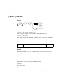
SCPI commands are based on a hierarchical structure, similar to the file
systems used by many bus controllers. This hierarchical structure is also
known as a tree system. In this system, associated commands are grouped
together under a common node or root, thus forming subsystems. You
must specify the complete path to execute the individual lower- level
commands. A portion of the CALibration subsystem is shown below to
illustrate the tree system:
CALibration:
SECure:
STATe {OFF|ON|RESET}, <code>
STATe?
CALibration:
SECure:
CODE <new code>
CALibration is the root keyword of the command, SECure is a
second-level keyword, and STATe and CODE are third-level keywords. A
colon ( : ) separates a command keyword from a lower-level keyword.
Mnemonic forms
Each keyword has both a long and a short form. A standard notation is
used to differentiate the short form keyword from the long form keyword.
The long form of the keyword is shown, with the short form portion
shown in uppercase characters, and the rest of the keyword shown in
lowercase characters. For example, the short form of CALibration is
CAL.
For shorter program lines, you can send the abbreviated form. For better
program readability, you can send the long form. For example, in the
above syntax statement, CALibration and CAL are both acceptable forms.
You can use a mixture of uppercase and lowercase letters. Therefore,
CALIBRATION, cal, and Cal are all acceptable. Other forms, such as CA
and cali, are not valid and will generate an error.
2
U2761A Programmer’s Reference
Introduction to SCPI
1
SCPI Conventions and Data Formats
Command separators
Using a colon ( : )
A colon ( : ) is used to separate a command keyword from a lower- level
keyword. When a colon is inserted between two command mnemonics, the
colon moves the path down one level in the present path (for the specified
root- level command) of the command tree. You must separate command
mnemonics from each other using a colon as shown below:
→ FUNC:RAMP:SYMM 50
An error is generated if you do not use the colon in your command string:
→ FUNC RAMP SYMM 50
→ SYST:ERR?
Typical response:
← –103,"Invalid separator"
NOTE
“→” indicates the commands that you send to the U2761A.
“←” indicates the response from the U2761A.
Using a semicolon ( ; )
A semicolon ( ; ) is used to separate commands within the same
subsystem, and can also minimize typing. For example, sending the
following command string:
→ FREQ:STAR 10; STOP 1000
... is the same as sending the following two commands:
→ FREQ:STAR 10
→ FREQ:STOP 1000
U2761A Programmer’s Reference
3
1
Introduction to SCPI
Use a semicolon and a colon to link commands from different subsystems.
For example, in the following command string, an error is generated if you
do not use both the semicolon and colon:
→ SWE:STAT ON;:TRIG:SOUR EXT
Using a comma ( , )
If a command requires more than one parameter, you must separate
adjacent parameters using a comma as shown in the following example:
→ APPL:SIN 5 KHZ, 3.0 VPP, –2.5 V
Using whitespace
You must use whitespace characters, [tab], or [space] to separate a
parameter from a command keyword. Whitespace characters are generally
ignored only in parameter lists.
Using “?” commands
The bus controller may send commands at any time, but a SCPI
instrument may only send responses when specifically instructed to do so.
Only query commands (commands that end with a “?”) will instruct the
instrument to send a response message. Queries return either measured
values or internal instrument settings.
For example, the following command sets the output frequency to 5 kHz:
→ FREQ 5000
You can then query the current range setting by sending:
→ FREQ?
Typical response:
← +5.0000000000000E+03
NOTE
4
If you send two query commands without reading the response from the first, then attempt to
read the second response, you may receive some data from the first response followed by the
complete second response. To avoid this, do not send a query command without reading the
response. When you cannot avoid this situation, send a device clear before sending the
second query command. For more information on device clear, refer to “Using device
clear” on page 10.
U2761A Programmer’s Reference
Introduction to SCPI
1
Using “ * ” commands
Commands starting with a “*” are called common commands. They are
required to perform the identical function for all instruments that are
compliant with the IEEE- 488.2 interface standard.
The IEEE- 488.2 standard defines a set of common commands that perform
functions such as reset, self- test, and status operations. Common
commands always begin with an asterisk (*), are three characters in
length, and may include one or more parameters.
Syntax conventions
The following SCPI conventions are used throughout this guide.
Braces “{ }”
Braces “{ }” enclose the parameter choices for a given command string.
For example, the syntax statement below shows that you need to select an
output function:
[SOURce:]FUNCtion[:SHAPe] {SINusoid|SQUare|RAMP|PULSe|DC|USER}
The braces are not sent with the command string. A vertical bar “|”
separates multiple parameter choices for a given command string.
Triangle brackets “< >”
Triangle brackets “< >” indicate that you must specify a value for the
enclosed parameter. For example, the syntax statement below shows the
<value> parameter enclosed in triangle brackets:
CALibration:VALue <value>
The brackets are not sent with the command string. You must specify a
value for the parameter:
CALibration:VALue 1E+7
U2761A Programmer’s Reference
5
1
Introduction to SCPI
Square brackets “[ ]”
Some commands and parameters are enclosed in square brackets “[ ]”.
Items within the square brackets are optional and can be omitted. For
example, the syntax statement below shows that SOURce: is optional and
can be omitted:
[SOURce:]PULSe:PERiod <seconds>
PULSe:PERiod <seconds>
The brackets are not sent with the command string.
Parenthesis “( )”
Parameters within parentheses are used to specify an address list. The
notation (@1) specifies address 1. The notation (@1,3) specifies an
address list of 1 and 3. For example, an address list of 0 and 1 is
specified in the following command:
→ CONF:SSI MAST, (@0,1)
6
U2761A Programmer’s Reference
Introduction to SCPI
1
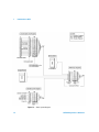
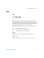
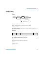
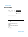
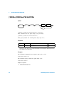
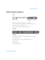
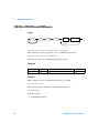
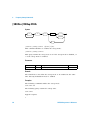
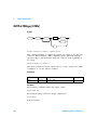
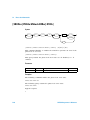
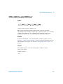
Syntax diagram conventions
Root
keyword
Second
level
Third
level
space
Option 1
,
Parameter
Option 2
Option 3
Figure 1-1 Typical syntax diagram
Solid lines represent the recommended path.
Ovals enclose the short form command mnemonics.
The command mnemonic must be entered exactly as
shown. Ovals are also used to represent discrete
parameters and command separators.
Rectangles enclose the parameters required. Refer to
“Data types and formats” on page 8 for a complete list
of the various data types and formats used throughout
this guide. Rectangles are also used to represent white
space.
Dotted lines indicate an optional path for bypassing
secondary keywords.
Arrows and curved intersections indicate command
path direction.
U2761A Programmer’s Reference
7
1
Introduction to SCPI
Data types and formats
The SCPI language defines different data formats for use in program
messages and response messages. Instruments are flexible listeners and
can accept commands and parameters in various formats. However, SCPI
instruments are precise talkers. This means that SCPI instruments always
respond to a particular query in a predefined, rigid format.
Numeric
Parameters that accept all commonly used decimal representations of
numbers including optional signs, decimal points, and scientific notation.
You can also send engineering unit suffixes with numeric parameters such
as Mhz or Khz. If only specific numeric values are accepted, the
instrument will automatically round the input numeric parameters. The
following command uses a numeric parameter:
[SOURce:]FM:INTernal:FREQuency <frequency>
Discrete
Parameters used to program settings that have a limited number of values
such as BUS, IMMediate, and EXTernal. Some of these parameters have
a short form and a long form just like command keywords. You can mix
uppercase and lowercase letters. Query responses will always return the
short form in all uppercase letters. The following command uses discrete
parameters:
[SOURce:]SWEep:SPACing {LINear|LOGarithmic}
Boolean
Parameters that represent a single binary condition that is either true or
false. For a false condition, the U2761A will accept OFF or 0. For a true
condition, the U2761A will accept ON or 1. When you query a boolean
setting, the U2761A will always return 0 or 1. The following command
uses boolean parameters:
OUTPut[:STATe] {0|OFF|1|ON}
8
U2761A Programmer’s Reference
Introduction to SCPI
1
String
Parameters that contain virtually any set of ASCII characters. A string
must begin and end with matching quotes; either with a single quote or a
double quote. You can include the quote delimiter as part of the string by
typing it twice without any characters in between. The following command
uses a string parameter:
CALibration:STRing <quoted string>
Address list
An address list must be preceded with the “@” symbol and must be
enclosed in parentheses “( )”. Use the following syntax to specify the
U2761A address list:
(@<address>[,<address>])
The address list parameter allows you to specify a single address or
multiple addresses.
For example, address 1 is specified in the following command:
→ CONF:SSI SLAV, (@1)
An address list of 1 and 3 is specified in the following command:
→ CONF:SSI MAST, (@1,3)
NOTE
The CONFigure:SSI command is the only U2761A command that uses the address list
parameter.
Input message terminators
Program messages sent to a SCPI instrument must terminate with a
<newline> character. The IEEE-488 End-Of-Identify (EOI) signal is
interpreted as a <newline> character and may also be used to terminate a
message in place of the <newline> character. A <carriage return> followed
by a <newline> is also accepted. Many programming languages allow you
to specify a message terminator character or EOI state to be automatically
sent with each bus transaction. Message termination always sets the
current path back to the root level.
U2761A Programmer’s Reference
9
1
Introduction to SCPI
Using device clear
Device clear is an IEEE- 488 low- level bus message that you can use to
return the instrument to a responsive state (for example, during a lengthy
query).
Different programming languages and IEEE- 488 interface cards provide
access to this capability through their own unique commands. The status
registers, the error queue, and all configuration states are left unchanged
when a device clear message is received.
Device clear performs the following actions:
• The instrument’s input and output buffers are cleared.
• The instrument is prepared to accept a new command string.
An overlapped command, if any, will be terminated with no “Operation
Complete” indication.
10
U2761A Programmer’s Reference
Introduction to SCPI
1
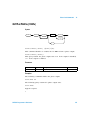
SCPI Status System
The status system records various instrument conditions and states in
several register groups. Each register group is made up of several low-level
registers called Condition register, Event register, and Enable register
which control the action of specific bits within the register group.
A Condition register continuously monitors the state of the instrument.
The bits in the condition register are updated in realtime and the bits are
not latched or buffered. This is a read- only register and the bits are not
cleared when you read the register.
An Event register latches the various events from the changes in the
condition register. There is no buffering in this register; while an event bit
is set, subsequent events corresponding to that bit are ignored. This is a
read- only register. Once a bit is set, it remains set until cleared by a
query or clear status (*CLS) command.
An Enable register defines which bits in the event register will be reported
to the Status Byte register group. You can write to or read from an enable
register.
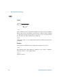
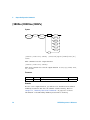
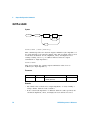
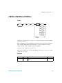
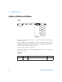
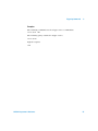
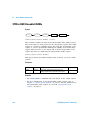
The relationship between various registers in the U2761A SCPI status
system is shown in Figure 1- 2.
U2761A Programmer’s Reference
11
1
Introduction to SCPI
Figure 1-2 Status system diagram
12
U2761A Programmer’s Reference
Introduction to SCPI
1
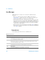
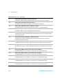
Questionable Data register
The Questionable Data register group provides the information on the
quality or integrity of the U2761A. The outputs of the Questionable Data
group are logically-ORed into the Questionable summary bit (3) of the
Status Byte register.
Bit definitions: Questionable Data register
Bit number
Decimal value
Definition
0 to 3 Not Used
Not Used
0 is returned
4 Over Temperature
16
Internal temperature is over the limit. The U2761A is automatically
reset to the default factory settings.
5 Loop Unlocked
32
The internal phase-lock loop is unlocked. Frequency accuracy will
be affected
6 to 7 Not Used
Not Used
0 is returned.
8 Calibration Error
256
Error occurred during calibration or the calibration memory is lost
9 External Reference
512
External phase reference is being used
10 to 15 Not Used
Not Used
0 is returned
The STATus:PRESet command will clear all bits in the enable register.
U2761A Programmer’s Reference
13
1
Introduction to SCPI
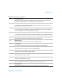
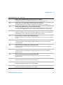
Standard Event register
The Standard Event register group reports the following types of
instrument events: power on detected, command syntax errors, command
execution errors, device errors (self-test or calibration), query errors, or
when an *OPC command is executed. All of these conditions can be
reported in the Standard Event summary bit through the enable register.
To set the enable register mask, key in a decimal value to the register
using the event status enable (*ESE)command.
Bit definitions: Standard Event register
Bit number
Decimal value
Definition
0 Operation Complete
1
All commands prior to and including *OPC have been executed
1 Not Used
Not Used
0 is returned
2 Query Error
4
The U2761A tried to read the output buffer but it was empty. Or, a
new command line was received before a previous query has been
read. Or, both the input and output buffers are full.
3 Device Error
8
A self-test, calibration, or other device-specific error has occurred
4 Execution Error
16
A command execution error occurred
5 Command Error
32
A command syntax error occurred
6 Not Used
Not Used
0 is returned
7 Power On
128
Power has been turned off and on since the last time the event
register was read or cleared
The event register in the Standard Event is cleared when:
• you execute the clear status (*CLS)command
• querying the event register using the event status register (*ESR?)
command
The Standard Event enable register is cleared when you execute the
*ESE 0 command.
NOTE
• When the command, execution, device, and query errors occurred, the related error
messages will be generated.
• For a complete listing of the error messages, refer to Chapter 16, “Error Messages” on
page 141.
14
U2761A Programmer’s Reference
Introduction to SCPI
1
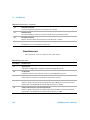
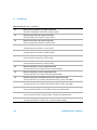
Status Byte register
The Status Byte register group reports the conditions from the other
status registers. Clearing an event register from one of the other registers
will clear the corresponding bits in the Status Byte condition register.
Data that is waiting in the U2761A output buffer is immediately reported
on the “Message Available” bit (bit 4).
Bit definitions: Status Byte register
Bit number
Decimal
value
Definition
0 to 1 Not Used
Not Used
0 is returned
2 Error Queue
4
There is at least one error message in the error queue
3 Questionable Data Summary
8
One or more bits are set in the Questionable Data register (bits
must be enabled in the enable register)
4 Message Available
16
Data is available in the U2761A output buffer
5 Event Status Byte Summary
32
One or more bits are set in the Standard Event register (bits must
be enabled in the enable register)
6 Master Status Summary
(Request for Service)
64
One or more bits are set in the Status Byte register (bits must be
enabled in the enable register). Also used to indicate a request for
service.
7 Not Used
Not Used
0 is returned
The Status Byte condition register will be cleared when:
• you execute the clear status (*CLS) command
• you read the event register from one of the other register groups, only
the corresponding bits are cleared in the condition register
The Status Byte enable register is cleared when you execute the *SRE 0
command.
NOTE
Refer to Chapter 2, “IEEE-488.2 Common Commands” on page 17 for details of the common
IEEE commands mentioned above.
U2761A Programmer’s Reference
15
1
16
Introduction to SCPI
U2761A Programmer’s Reference
Agilent U2761A USB Modular Function/Arbitrary Waveform Generator
Programmer’s Reference
2
IEEE-488.2 Common Commands
*CLS
*ESE
*ESR?
*IDN?
*OPC
*RST
*SRE
*STB?
*TRG
*TST?
*WAI
18
19
20
21
22
23
24
26
27
28
29
This section describes the IEEE-488.2 common commands supported by
the U2761A.
Agilent Technologies
17
2
IEEE-488.2 Common Commands
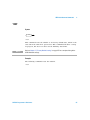
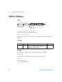
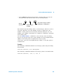
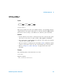
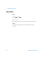
*CLS
Syntax
*CLS
*CLS
This command is used to clear the event registers in all register groups,
and also clears the error queue.
Example
The following command clears the event register bits.
*CLS
18
U2761A Programmer’s Reference
IEEE-488.2 Common Commands
2
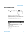
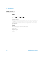
*ESE
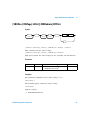
Syntax
*ESE
space
value
?
*ESE <value>
This command sets the bits in the Standard Event enable register. The
selected bits are then reported to bit 5 of the Status Byte register.
*ESE?
This query reads the enable register and returns a decimal value which
corresponds to the binary- weighted sum of all bits set in the register.
Parameter
Item
Type
Range of values
Default value
value
Numeric
A decimal value which corresponds to the
binary-weighted sum of the bits in the register
0
Remarks
For more information on the Standard Event register, refer to Chapter 1,
“Status system diagram” on page 12. The bit definitions for the Standard
Event register are listed in “Standard Event register” on page 14.
Examples
The following command enables bit 4 (decimal value = 16) in the enable
register.
*ESE 16
The following query returns the bits enabled in the register.
*ESE?
Typical response:
+16
U2761A Programmer’s Reference
19
2
IEEE-488.2 Common Commands
*ESR?
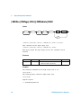
Syntax
*ESR
?
*ESR?
This query reads the event register of the Standard Event register group
and returns a decimal value which corresponds to the binary- weighted
sum of all bits set in the register.
Remarks
• Once a bit is set, it will remain set until cleared by a clear status
(*CLS) command or queried by this command.
• For more information on the Standard Event register, refer to
Chapter 1, “Status system diagram” on page 12. The bit definitions for
the Standard Event register are listed in “Standard Event register” on
page 14.
Example
The following query reads the event register (assumed that bit 4 is set)
*ESR?
Typical response:
+16
20
U2761A Programmer’s Reference
IEEE-488.2 Common Commands
2
*IDN?
Syntax
*IDN
?
*IDN?
This query reads the U2761A identification string which contains four
comma-separated fields. The first field is the manufacturer's name, the
second field is the model number of the U2761A, the third field is the
serial number, and the fourth field is the firmware revision number. This
query returns an ASCII string with the following format.
AGILENT TECHNOLOGIES,U2761A,<Serial Number>,m.mm-f.ff- b.bb
m.mm = main firmware revision number
f.ff
= I/O processor firmware revision number
b.bb
= boot loader firmware revision number
Example
The following query returns the U2761A identification string.
*IDN?
Typical response:
AGILENT TECHNOLOGIES,U2761A,MY12345678,1.00-1.00-1.00
U2761A Programmer’s Reference
21
2
IEEE-488.2 Common Commands
*OPC
Syntax
*OPC
?
*OPC
This command sets the “Operation Complete” bit (bit 0) in the Standard
Event register when all pending operations have completed. This command
is used in the triggered sweep mode to provide a way to poll (interrupt)
the PC when the *TRG command has completed.
*OPC?
This query sends 1 to the output buffer when all pending operations have
completed.
Examples
The following command sets the “Operation Complete” bit (bit 0).
*OPC
The following query waits until the completion of the current command
and then sends 1 to the output buffer.
*OPC?
Typical response:
1
22
U2761A Programmer’s Reference
IEEE-488.2 Common Commands
2
*RST
Syntax
*RST
*RST
This command resets the U2761A to its factory default state, which is the
state when the U2761A is powered on. This command will abort a sweep
in progress, but does not affect stored Arbitrary waveforms.
NOTE
Refer to Chapter 17, “Factory Default Settings” on page 157 for a complete listing of the
U2761A default settings.
Example
The following command resets the U2761A.
*RST
U2761A Programmer’s Reference
23
2
IEEE-488.2 Common Commands
*SRE
Syntax
*SRE
space
value
?
*SRE <value>
This command enables the bits in the Status Byte enable register. The
selected enabled bits are summarized in the “Master Summary” bit (bit 6)
of the Status Byte register. If any of the selected bit condition changes
from 0 to 1, a Service Request is generated.
*SRE?
This query reads the enable register and returns a decimal value that
corresponds to the binary-weighted sum of all bits set in the register.
Parameter
Item
Type
Range of values
Default value
value
Numeric
A decimal value which corresponds to the
binary-weighted sum of the bits in the register
0
Remarks
For more information on the Status Byte register, refer to Chapter 1,
“Status system diagram” on page 12. The bit definitions for the Status
Byte register are listed in “Status Byte register” on page 15.
Examples
The following command enables bit 4 (decimal value = 16) in the enable
register.
*SRE 16
24
U2761A Programmer’s Reference
IEEE-488.2 Common Commands
2
The following query returns the bit enabled in the register.
*SRE?
Typical response:
+16
U2761A Programmer’s Reference
25
2
IEEE-488.2 Common Commands
*STB?
Syntax
*STB
?
*STB?
This query reads the summary (condition) of the Status Byte register and
returns a decimal value which corresponds to the binary- weighted sum of
all bits set in the register. This query is similar to a Serial Poll but it is
processed like any other instrument command. This is a read- only register
and the bits are not cleared when you read the register.
Remarks
• For more information on the Status Byte register, refer to Chapter 1,
“Status system diagram” on page 12. The bit definitions for the Status
Byte register are listed in “Status Byte register” on page 15.
• This query returns the same results as a Serial Poll but the “Master
Summary” bit (bit 6) is not cleared if a Serial Poll has occurred.
Example
The following query reads the condition register (assumed that bits 3 and
4 are set).
*STB?
Typical response:
+24
26
U2761A Programmer’s Reference
IEEE-488.2 Common Commands
2
*TRG
Syntax
*TRG
*TRG
This command triggers a sweep from the remote interface only if the bus
(software) trigger source is currently selected.
Example
The following command triggers a sweep.
*TRG
U2761A Programmer’s Reference
27
2
IEEE-488.2 Common Commands
*TST?
Syntax
*TST
?
*TST?
This query performs a self-test on the U2761A and returns +0 (pass) or +1
(fail). If the test fails, one or more error messages will be generated to
provide additional information on the failure.
Example
The following query returns the self-test status.
*TST?
Typical response:
+0
28
U2761A Programmer’s Reference
IEEE-488.2 Common Commands
2
*WAI
Syntax
*WAI
*WAI
This command sets the U2761A to wait for the completion of all pending
operations before executing any additional command over the interface.
Example
The following command sets the U2761A to wait until all pending
operations have completed.
*WAI
U2761A Programmer’s Reference
29
2
30
IEEE-488.2 Common Commands
U2761A Programmer’s Reference
Agilent U2761A USB Modular Function/Arbitrary Waveform Generator
Programmer’s Reference
3
APPLy Commands
Using the APPLy Command 32
APPLy:SINusoid 33
APPLy:SQUare 34
APPLy:RAMP 35
APPLy:PULSe 36
APPLy:DC 37
APPLy:USER 38
APPLy? 39
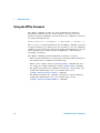
This section describes the APPLy commands used to program the U2761A
over the remote interface. The waveform is output as soon as the APPLy
command is executed for each function.
Agilent Technologies
31
3
APPLy Commands
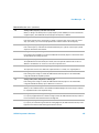
Using the APPLy Command
The APPLy command provides the most straightforward method to
program the U2761A over the remote interface. You can select the
function, frequency, amplitude, and offset all in one command as shown in
the syntax statement below:
APPLy:<function> [<frequency> [,<amplitude> [,<offset>] ]]
Due to the use of optional parameters in the APPLy commands (enclosed
in square brackets), you must specify the frequency to use the amplitude
parameter, and you must specify both frequency and amplitude to use the
offset parameter. You cannot specify an amplitude or offset without
specifying a frequency.
The APPLy command performs additional operations as follows:
• Turns off any modulation or sweep mode currently enabled and places
the U2761A in the continuous waveform mode.
• Turns on the output connector (OUTPut[:STATe] command) but does
not change the output termination setting (OUTPut:LOAD command).
• For Square waveforms, the command overrides the current duty cycle
setting and automatically sets to the default value of 50%
([SOURce:]FUNCtion:SQUare:DCYCle command).
• For Ramp waveforms, the command overrides the current symmetry
setting and automatically sets to the default value of 100%
([SOURce:]FUNCtion:RAMP:SYMMetry command).
32
U2761A Programmer’s Reference
APPLy Commands
3
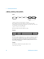
APPLy:SINusoid
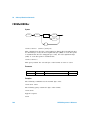
Syntax
APPL
:SIN
space
frequency
,
amplitude
,
offset
APPLy:SINusoid [<frequency> [,<amplitude> [,<offset>] ]]
This command outputs a Sine wave with the specified frequency,
amplitude, and DC offset. The waveform is output as soon as the
command is executed.
Parameters
Item
Type
Range of values
Default value
frequency
Numeric
1 μHz to 20 MHz
1 kHz
amplitude
Numeric
• 40 mVpp to 5 Vpp (Into 50 Ω load)
• 80 mVpp to 10 Vpp (Into open circuit)
1 Vpp
offset
Numeric
• ±2.48 V (Into 50 Ω load)
• ±4.96 V (Into open circuit)
0V
Example
The following command sets the output frequency to 2 kHz, output
amplitude to 1 Vpp, and output offset to 0 V.
APPL:SIN 2000, 1 VPP, 0
U2761A Programmer’s Reference
33
3
APPLy Commands
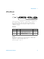
APPLy:SQUare
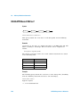
Syntax
APPL
:SQU
space
frequency
,
amplitude
,
offset
APPLy:SQUare [<frequency> [,<amplitude> [,<offset>] ]]
This command outputs a Square wave with the specified frequency,
amplitude, and DC offset. The waveform is output as soon as the
command is executed.
Parameters
Item
Type
Range of values
Default value
frequency
Numeric
1 μHz to 20 MHz
1 kHz
amplitude
Numeric
• 40 mVpp to 5 Vpp (Into 50 Ω load)
• 80 mVpp to 10 Vpp (Into open circuit)
1 Vpp
offset
Numeric
• ±2.48 V (Into 50 Ω load)
• ±4.96 V (Into open circuit)
0V
Remark
This command overrides the current duty cycle setting and automatically
sets to the default value of 50%.
Example
The following command sets the output frequency to 5 kHz, output
amplitude to 5 Vpp, and output offset to 0 V.
APPL:SQU 5000, 5 VPP, 0
34
U2761A Programmer’s Reference
APPLy Commands
3
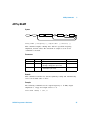
APPLy:RAMP
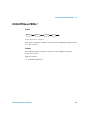
Syntax
APPL
:RAMP
space
frequency
,
amplitude
,
offset
APPLy:RAMP [<frequency> [,<amplitude> [,<offset>] ]]
This command outputs a Ramp wave with the specified frequency,
amplitude, and DC offset. The waveform is output as soon as the
command is executed.
Parameters
Item
Type
Range of values
Default value
frequency
Numeric
1 μHz to 200 kHz
1 kHz
amplitude
Numeric
• 40 mVpp to 5 Vpp (Into 50 Ω load)
• 80 mVpp to 10 Vpp (Into open circuit)
1 Vpp
offset
Numeric
• ±2.48 V (Into 50 Ω load)
• ±4.96 V (Into open circuit)
0V
Remark
This command overrides the current symmetry setting and automatically
sets to the default value of 100%.
Example
The following command sets the output frequency to 10 kHz, output
amplitude to 1 Vpp, and output offset to 0 V.
APPL:RAMP 10000, 1 VPP, 0
U2761A Programmer’s Reference
35
3
APPLy Commands
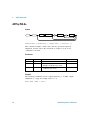
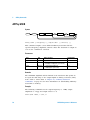
APPLy:PULSe
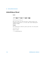
Syntax
APPL
:PULS
space
frequency
,
amplitude
,
offset
APPLy:PULSe [<frequency> [,<amplitude> [,<offset>] ]]
This command outputs a Pulse wave with the specified frequency,
amplitude, and DC offset. The waveform is output as soon as the
command is executed.
Parameters
Item
Type
Range of values
Default value
frequency
Numeric
500 μHz to 5 MHz
1 kHz
amplitude
Numeric
• 40 mVpp to 5 Vpp (Into 50 Ω load)
• 80 mVpp to 10 Vpp (Into open circuit)
1 Vpp
offset
Numeric
• ±2.48 V (Into 50 Ω load)
• ±4.96 V (Into open circuit)
0V
Example
The following command sets the output frequency to 1.5 kHz, output
amplitude to 3 Vpp, and output offset to 1 V.
APPL:PULS 1500, 3 VPP, 1
36
U2761A Programmer’s Reference
APPLy Commands
3
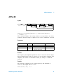
APPLy:DC
Syntax
APPL
:DC
space
frequency
,
DEF
amplitude
,
offset
DEF
APPLy:DC [<frequency|DEFault> [,<amplitude>|DEFault>
[,<offset>] ]]
This command outputs a DC voltage with the level specified by the offset
parameter. The DC voltage is output as soon as the command is executed.
Parameters
Item
Type
Range of values
Default value
frequency|DEFault
Numeric
N/A
DEFault
amplitude|DEFault
Numeric
N/A
DEFault
offset
Numeric
• ±2.5 V (Into 50 Ω load)
• ±5 V (Into open circuit)
0V
Remarks
The frequency and amplitude parameters have no effect for the DC output
but you must specify a value or DEFault. If you specify a frequency and
amplitude, the values are remembered when you change to a different
function.
Example
The following command sets the output frequency and amplitude to
DEFault, and output offset to –2.5 V.
APPL:DC DEF, DEF, –2.5
U2761A Programmer’s Reference
37
3
APPLy Commands
APPLy:USER
Syntax
APPL
:USER
space
frequency
,
amplitude
,
offset
APPLy:USER [<frequency> [,<amplitude> [,<offset>] ]]
This command outputs a user- defined Arbitrary waveform with the
specified frequency, amplitude, and DC offset. The waveform is output as
soon as the command is executed.
Parameters
Item
Type
Range of values
Default value
frequency
Numeric
1 μHz to 200 kHz
1 kHz
amplitude
Numeric
• 40 mVpp to 5 Vpp (Into 50 Ω load)
• 80 mVpp to 10 Vpp (Into open circuit)
1 Vpp
offset
Numeric
• ±2.48 V (Into 50 Ω load)
• ±4.96 V (Into open circuit)
0V
Remarks
The maximum amplitude will be limited if the waveform data points do
not span the full range of the output Digital- to- Analog Converter (DAC)
from –8191 to +8191. Refer to Chapter 10, “Arbitrary Waveform
Commands” on page 103 for more information on downloading Arbitrary
waveforms to memory.
Example
The following command sets the output frequency to 1 kHz, output
amplitude to 2 Vpp, and output offset to 0 V.
APPL:USER 1000, 2 VPP, 0
38
U2761A Programmer’s Reference
APPLy Commands
3
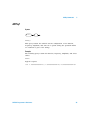
APPLy?
Syntax
APPL
?
APPLy?
This query returns the U2761A current configuration of the function,
frequency, amplitude, and offset in a quoted string (the quotation marks
are returned as part of the string).
Example
The following query returns the function, frequency, amplitude, and offset
values.
APPL?
Typical response:
"SIN +1.0000000000000E+03,+1.0000000000000E+00,+0.0000000000000E+00"
U2761A Programmer’s Reference
39
3
40
APPLy Commands
U2761A Programmer’s Reference
Agilent U2761A USB Modular Function/Arbitrary Waveform Generator
Programmer’s Reference
4
Output Configuration Commands
[SOURce:]FUNCtion[:SHAPe] 42
[SOURce:]FREQuency 44
[SOURce:]VOLTage[:LEVel][:IMMediate][:AMPLitude] 45
[SOURce:]VOLTage[:LEVel][:IMMediate]:OFFSet 47
[SOURce:]VOLTage[:LEVel][:IMMediate]:HIGH 48
[SOURce:]VOLTage[:LEVel][:IMMediate]:LOW 49
[SOURce:]VOLTage[:LEVel][:IMMediate]:UNIT 50
[SOURce:]FUNCtion:SQUare:DCYCle 51
[SOURce:]FUNCtion:RAMP:SYMMetry 52
OUTPut[:STATe] 53
OUTPut:LOAD 54
This section describes the low- level commands used to program the
U2761A output configuration. These commands allow you to configure the
output function, frequency, amplitude and unit, offset voltage, high/low
voltage level, duty cycle, symmetry, as well as output state and
termination.
Agilent Technologies
41
4
Output Configuration Commands
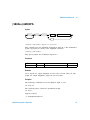
[SOURce:]FUNCtion[:SHAPe]
Syntax
SOUR :
FUNC
:SHAP
space
SIN
SQU
RAMP
PULS
DC
USER
?
[SOURce:]FUNCtion[:SHAPe] {SINusoid|SQUare|RAMP|PULSe|DC|
USER}
This command sets the output function.
[SOURce:]FUNCtion[:SHAPe]?
This query returns the selected output function as SIN, SQU, RAMP, PULS,
DC, or USER.
Parameter
Item
Type
Range of values
Default value
function
Discrete
SINusoid|SQUare|RAMP|PULSe|DC|USER
SINusoid
Remarks
For the USER output function, you will need to download user- defined
Arbitrary waveform data into the U2761A volatile memory. Refer to
Chapter 10, “Arbitrary Waveform Commands” on page 103 for more
information on downloading Arbitrary waveforms to memory.
42
U2761A Programmer’s Reference
Output Configuration Commands
4
Examples
The following command sets the output function to Square.
FUNC SQU
The following query returns the output function.
FUNC?
Typical response:
SQU
U2761A Programmer’s Reference
43
4
Output Configuration Commands
[SOURce:]FREQuency
Syntax
SOUR :
FREQ
space
frequency
?
[SOURce:]FREQuency <frequency>
This command sets the output frequency.
[SOURce:]FREQuency?
This query returns the frequency setting in Hz for the currently selected
function.
Parameter
Item
Type
Range of values
Default value
frequency
Numeric
• 1 μHz to 20 MHz (for sine and square)
• 1 μHz to 200 kHz (for ramp and arbitrary)
• 500 μHz to 5 MHz (for pulse)
1 kHz
Examples
The following command sets the output frequency to 2 kHz.
FREQ 2000
The following query returns the output frequency setting.
FREQ?
Typical response:
+2.0000000000000E+03
44
U2761A Programmer’s Reference
Output Configuration Commands
4
[SOURce:]VOLTage[:LEVel][:IMMediate][:AMPLitude]
Syntax
SOUR :
VOLT
:LEV
:IMM
:AMPL
space
amplitude
VPP
VRMS
DBM
?
[SOURce:]VOLTage[:LEVel][:IMMediate][:AMPLitude]
<amplitude> [VPP|VRMS|DBM]
This command sets the output amplitude with optional unit.
[SOURce:]VOLTage[:LEVel][:IMMediate][:AMPLitude]?
This query returns the output amplitude for the currently selected
function and unit. Values are always returned in the units set by the most
recent [SOURce:]VOLTage[:LEVel][:IMMediate]:UNIT command.
Parameter
Item
Type
Range of values
Default value
amplitude
Numeric
• 40 mVpp to 5 Vpp (Into 50 Ω load)
• 80 mVpp to 10 Vpp (Into open circuit)
1 Vpp
Remarks
The RMS and dBm values can be computed as follows:
Vrms = Vpeak / Crest factor
dBm = 10 × log10(P / 0.001), where P = Vrms2 / RLoad[1]
[1] For the load resistance values, refer to “OUTPut:LOAD” on page 54.
U2761A Programmer’s Reference
45
4
Output Configuration Commands
Examples
The following command sets the output amplitude to 5 Vpp.
VOLT 5 VPP
The following query returns the output amplitude.
VOLT?
Typical response:
+5.0000000000000E+00
46
U2761A Programmer’s Reference
Output Configuration Commands
4
[SOURce:]VOLTage[:LEVel][:IMMediate]:OFFSet
Syntax
SOUR :
VOLT
:LEV
:IMM
:OFFS
space
offset
?
[SOURce:]VOLTage[:LEVel][:IMMediate]:OFFSet <offset>
This command sets the offset voltage.
[SOURce:]VOLTage[:LEVel][:IMMediate]:OFFSet?
This query returns the offset voltage for the currently selected function.
Parameter
Item
offset
Type
Numeric
Range of values
Default value
load)[1]
• ±2.48 V (Into 50 Ω
• ±4.96 V (Into open circuit)[1]
0V
[1] For the DC function, the range of values are ±2.5 V (into 50 Ω load) and ±5 V (into open circuit).
Examples
The following command sets the offset voltage to 1 V.
VOLT:OFFS 1
The following query returns the offset voltage.
VOLT:OFFS?
Typical response:
+1.0000000000000E+00
U2761A Programmer’s Reference
47
4
Output Configuration Commands
[SOURce:]VOLTage[:LEVel][:IMMediate]:HIGH
Syntax
SOUR :
VOLT
:LEV
:IMM
:HIGH
space
voltage
?
[SOURce:]VOLTage[:LEVel][:IMMediate]:HIGH <voltage>
This command sets the high voltage level.
[SOURce:]VOLTage[:LEVel][:IMMediate]:HIGH?
This query returns the high voltage level for the currently selected
function.
Parameter
Item
Type
Range of values
Default value
voltage
Numeric
• –2.46 V to 2.5 V (Into 50 Ω load)
• –4.92 V to 5 V (Into open circuit)
0.5 V
Examples
The following command sets the high voltage level to 2 V.
VOLT:HIGH 2
The following query returns the high voltage level.
VOLT:HIGH?
Typical response:
+2.0000000000000E+00
48
U2761A Programmer’s Reference
Output Configuration Commands
4
[SOURce:]VOLTage[:LEVel][:IMMediate]:LOW
Syntax
SOUR :
VOLT
:LEV
:IMM
:LOW
space
voltage
?
[SOURce:]VOLTage[:LEVel][:IMMediate]:LOW <voltage>
This command sets the low voltage level.
[SOURce:]VOLTage[:LEVel][:IMMediate]:LOW?
This query returns the low voltage level for the currently selected
function.
Parameter
Item
Type
Range of values
Default value
voltage
Numeric
• –2.5 V to 2.46 V (Into 50 Ω load)
• –5 V to 4.92 V (Into open circuit)
–0.5 V
Examples
The following command sets the low voltage level to –2 V.
VOLT:LOW –2
The following query returns the low voltage level.
VOLT:LOW?
Typical response:
–2.0000000000000E+00
U2761A Programmer’s Reference
49
4
Output Configuration Commands
[SOURce:]VOLTage[:LEVel][:IMMediate]:UNIT
Syntax
SOUR :
VOLT
:LEV
:IMM
:UNIT
space
VPP
VRMS
DBM
?
[SOURce:]VOLTage[:LEVel][:IMMediate]:UNIT {VPP|VRMS|DBM}
This command sets the unit for the output amplitude.
[SOURce:]VOLTage[:LEVel][:IMMediate]:UNIT?
This query returns the unit for the output amplitude as VPP, VRMS, or
DBM.
Parameter
Item
Type
Range of values
Default value
unit
Discrete
VPP|VRMS|DBM
VPP
Examples
The following command sets the unit of the output amplitude to Vpp.
VOLT:UNIT VPP
The following query returns the output amplitude unit.
VOLT:UNIT?
Typical response:
VPP
50
U2761A Programmer’s Reference
Output Configuration Commands
4
[SOURce:]FUNCtion:SQUare:DCYCle
Syntax
SOUR :
FUNC
:SQU
:DCYC
space
percent
?
[SOURce:]FUNCtion:SQUare:DCYCle <percent>
This command sets the duty cycle percentage for the Square wave.
[SOURce:]FUNCtion:SQUare:DCYCle?
This query returns the current duty cycle setting in %.
Parameter
Item
Type
Range of values
Default value
percent
Numeric
• 20% to 80% (for frequency ≤ 10 MHz)
• 40% to 60% (for frequency > 10 MHz)
50%
Examples
The following command sets the duty cycle to 80%.
FUNC:SQU:DCYC 80
The following query returns the duty cycle.
FUNC:SQU:DCYC?
Typical response:
+8.0000000000000E+01
U2761A Programmer’s Reference
51
4
Output Configuration Commands
[SOURce:]FUNCtion:RAMP:SYMMetry
Syntax
SOUR :
FUNC
:RAMP
:SYMM
space
percent
?
[SOURce:]FUNCtion:RAMP:SYMMetry <percent>
This command sets the symmetry percentage for the Ramp wave.
[SOURce:]FUNCtion:RAMP:SYMMetry?
This query returns the current symmetry setting in %.
Parameter
NOTE
Item
Type
Range of values
Default value
percent
Numeric
0% to 100%
100%
Setting the symmetry to 50% will produce a Triangle wave, and 0% for a Negative Ramp
wave.
Examples
The following command sets the symmetry to 50%.
FUNC:RAMP:SYMM 50
The following query returns the symmetry.
FUNC:RAMP:SYMM?
Typical response:
+5.0000000000000E+01
52
U2761A Programmer’s Reference
Output Configuration Commands
4
OUTPut[:STATe]
Syntax
OUTP
:STAT
space
0|OFF
1|ON
?
OUTPut[:STATe] {0|OFF|1|ON}
This command disables or enables the U2761A output.
OUTPut[:STATe]?
This query returns the output state as 0 if the output is disabled, or 1 if
the output is enabled.
Parameter
Item
Type
Range of values
Default value
state
Boolean
0|OFF|1|ON
0
Examples
The following command turns on the output.
OUTP ON
The following query returns the output state.
OUTP?
Typical response:
1
U2761A Programmer’s Reference
53
4
Output Configuration Commands
OUTPut:LOAD
Syntax
OUTP
:LOAD
space
ohms
INF
?
OUTPut:LOAD {<ohms>|INFinity}
This command specifies the desired output termination (the impedance of
the load attached to the U2761A output) value. The specified value is used
in internal calculations for the amplitude, offset, and high/low level
settings. Setting INFinity or 9.9E+37 indicates that the output
termination is “high impedance”.
OUTPut:LOAD?
This query returns the current output termination value in Ω or
9.9E+37 (for “high impedance”).
Parameter
Item
Type
Range of values
Default value
load
Numeric
• 1 Ω to 10 kΩ
• INFinity (9.9E+37)
50 Ω
Remarks
• The U2761A has a fixed series output impedance of 50 Ω, forming a
voltage divider with the load resistance.
• If the actual load impedance is different than the value specified, the
calculated amplitude, offset, and high/low levels will be incorrect.
54
U2761A Programmer’s Reference
Output Configuration Commands
4
Examples
The following command specifies the output termination value as 2 kΩ.
OUTP:LOAD 2000
The following query returns the output termination value.
OUTP:LOAD?
Typical response:
+2.0000000000000E+03
U2761A Programmer’s Reference
55
4
56
Output Configuration Commands
U2761A Programmer’s Reference
Agilent U2761A USB Modular Function/Arbitrary Waveform Generator
Programmer’s Reference
5
Pulse Configuration Commands
[SOURce:]PULSe:PERiod 58
[SOURce:]FUNCtion:PULSe:HOLD 59
[SOURce:]FUNCtion:PULSe:WIDTh 60
[SOURce:]FUNCtion:PULSe:DCYCle 62
This section describes the Pulse configuration commands used to program
the U2761A to output a Pulse waveform. These commands allow you to
configure the pulse period, pulse hold, pulse width, and pulse duty cycle.
Agilent Technologies
57
5
Pulse Configuration Commands
[SOURce:]PULSe:PERiod
Syntax
SOUR :
PULS
:PER
space
seconds
?
[SOURce:]PULSe:PERiod <seconds>
This command sets the period for the Pulse wave.
[SOURce:]PULSe:PERiod?
This query returns the period of the Pulse wave in seconds.
Parameter
Item
Type
Range of values
Default value
seconds
Numeric
200 ns to 2000 s
1 ms
Examples
The following command sets the period to 1 s.
PULS:PER 1
The following query returns the pulse period.
PULS:PER?
Typical response:
+1.0000000000000E+00
58
U2761A Programmer’s Reference
Pulse Configuration Commands
5
[SOURce:]FUNCtion:PULSe:HOLD
Syntax
SOUR :
FUNC
:PULS
:HOLD
space
WIDT
DCYC
?
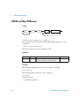
[SOURce:]FUNCtion:PULSe:HOLD {WIDTh|DCYCle}
This command sets the U2761A to hold either the pulse width or pulse
duty cycle setting constant as the period is varied.
[SOURce:]FUNCtion:PULSe:HOLD?
The query returns the pulse hold setting as WIDT or DCYC.
Parameter
Item
Type
Range of values
Default value
hold
Discrete
WIDTh|DCYCle
WIDTh
Examples
The following command sets the U2761A to hold the pulse width.
FUNC:PULS:HOLD WIDT
The following query returns the pulse hold setting.
FUNC:PULS:HOLD?
Typical response:
WIDT
U2761A Programmer’s Reference
59
5
Pulse Configuration Commands
[SOURce:]FUNCtion:PULSe:WIDTh
Syntax
SOUR :
FUNC
:PULS
:WIDT
space
seconds
?
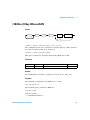
[SOURce:]FUNCtion:PULSe:WIDTh <seconds>
This command sets the pulse width in seconds. The pulse width
represents the time from the 50% threshold of the pulse rising edge to the
50% threshold of the next falling edge.
[SOURce:]FUNCtion:PULSe:WIDTh?
This query returns the pulse width in seconds.
Parameter
Item
Type
Range of values
Default value
seconds
Numeric
40 ns to 1999.99998 s
500 μs
Remarks
The specified pulse width must be less or equal to the difference between
the period and the minimum pulse width. The U2761A will adjust the
pulse width as necessary to accommodate the specified period. Refer to
the U2761A USB Modular Function/Arbitrary Waveform Generator User’s
Guide for more information.
Examples
The following command sets the pulse width to 2 ms.
FUNC:PULS:WIDT 0.002
60
U2761A Programmer’s Reference
Pulse Configuration Commands
5
The following query returns the pulse width.
FUNC:PULS:WIDT?
Typical response:
+2.0000000000000E–03
U2761A Programmer’s Reference
61
5
Pulse Configuration Commands
[SOURce:]FUNCtion:PULSe:DCYCle
Syntax
SOUR :
FUNC
:PULS
:DCYC
space
percent
?
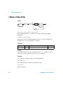
[SOURce:]FUNCtion:PULSe:DCYCle <percent>
This command sets the pulse duty cycle percentage.
[SOURce:]FUNCtion:PULSe:DCYCle?
This query returns the current pulse duty cycle in %.
Parameter
Item
percent
Type
Range of values
Default value
Numeric
0% to 100%[1]
50%
[1] The pulse duty cycle is limited by minimum pulse width restrictions which prevent you from setting
exactly 0% or 100%. Refer to the U2761A USB Modular Function/Arbitrary Waveform Generator
User’s Guide for more information.
Examples
The following command sets the pulse duty cycle to 50%.
FUNC:PULS:DCYC 50
The following query returns the pulse duty cycle.
FUNC:PULS:DCYC?
Typical response:
+5.0000000000000E+01
62
U2761A Programmer’s Reference
Agilent U2761A USB Modular Function/Arbitrary Waveform Generator
Programmer’s Reference
6
Modulation Commands
[SOURce:]AM:INTernal:FUNCtion 64
[SOURce:]AM:INTernal:FREQuency 66
[SOURce:]AM:DEPTh 67
[SOURce:]AM:STATe 68
[SOURce:]FM:INTernal:FUNCtion 69
[SOURce:]FM:INTernal:FREQuency 71
[SOURce:]FM:DEViation 72
[SOURce:]FM:STATe 73
[SOURce:]PM:INTernal:FUNCtion 74
[SOURce:]PM:INTernal:FREQuency 76
[SOURce:]PM:DEViation 77
[SOURce:]PM:STATe 78
This section describes the Modulation commands used to generate
modulations of the U2761A. These commands allow you to configure the
modulating waveform, frequency, and modulation state for each
modulation type, as well as the amplitude modulation depth and
frequency/phase deviation.
Agilent Technologies
63
6
Modulation Commands
[SOURce:]AM:INTernal:FUNCtion
Syntax
SOUR :
AM
:INT
:FUNC
space
SIN
SQU
RAMP
NRAM
TRI
USER
?
[SOURce:]AM:INTernal:FUNCtion {SINusoid|SQUare|RAMP|NRAMp|
TRIangle|USER}
This command sets the modulating waveform of the amplitude modulation.
The available modulating waveform types consist of sinusoid, square,
ramp, negative ramp, triangle, and user- defined.
[SOURce:]AM:INTernal:FUNCtion?
This query returns the selected modulating waveform as SIN, SQU, RAMP,
NRAM, TRI, or USER.
Parameter
64
Item
Type
Range of values
Default value
function
Discrete
SINusoid|SQUare|RAMP|NRAMp|TRIangle|
USER
SINusoid
U2761A Programmer’s Reference
Modulation Commands
6
Examples
The following command sets the modulating waveform to Sine.
AM:INT:FUNC SIN
The following query returns the modulating waveform.
AM:INT:FUNC?
Typical response:
SIN
U2761A Programmer’s Reference
65
6
Modulation Commands
[SOURce:]AM:INTernal:FREQuency
Syntax
SOUR :
AM
:INT
:FREQ
space
frequency
?
[SOURce:]AM:INTernal:FREQuency <frequency>
This command sets the frequency of the modulating waveform.
[SOURce:]AM:INTernal:FREQuency?
This query returns the modulating frequency in Hz.
Parameter
Item
Type
Range of values
Default value
frequency
Numeric
2 mHz to 20 kHz
100 Hz
Examples
The following command sets the modulating frequency to 500 Hz.
AM:INT:FREQ 500
The following query returns the modulating frequency.
AM:INT:FREQ?
Typical response:
+5.0000000000000E+02
66
U2761A Programmer’s Reference
Modulation Commands
6
[SOURce:]AM:DEPTh
Syntax
SOUR :
AM
:DEPT
space
depth in percent
?
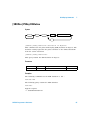
[SOURce:]AM:DEPTh <depth in percent>
This command sets the amplitude modulation depth in %. The modulation
depth represents the extent of the amplitude variation.
[SOURce:]AM:DEPTh?
This query returns the modulation depth in %.
Parameter
Item
Type
Range of values
Default value
depth
Numeric
0% to 100%
100%
Remarks
At 0% depth, the output amplitude is half of the selected value. At 100%
depth, the output amplitude equals the selected value.
Examples
The following command sets the modulation depth to 50%.
AM:DEPT 50
The following query returns the modulation depth.
AM:DEPT?
Typical response:
+5.0000000000000E+01
U2761A Programmer’s Reference
67
6
Modulation Commands
[SOURce:]AM:STATe
Syntax
SOUR :
AM
:STAT
space
0|OFF
1|ON
?
[SOURce:]AM:STATe {0|OFF|1|ON}
This command disables or enables the amplitude modulation.
[SOURce:]AM:STATe?
This query returns the amplitude modulation state as 0 if the modulation
is disabled, or 1 if the modulation is enabled.
Parameter
Item
Type
Range of values
Default value
state
Boolean
0|OFF|1|ON
0
Remark
The U2761A allows only one modulation mode to be enabled at a time,
and does not allow modulation when sweep is enabled.
Examples
The following command enables the amplitude modulation.
AM:STAT ON
The following query returns the modulation state.
AM:STAT?
Typical response:
1
68
U2761A Programmer’s Reference
Modulation Commands
6
[SOURce:]FM:INTernal:FUNCtion
Syntax
SOUR :
FM
:INT
:FUNC
space
SIN
SQU
RAMP
NRAM
TRI
USER
?
[SOURce:]FM:INTernal:FUNCtion {SINusoid|SQUare|RAMP|NRAMp|
TRIangle|USER}
This command sets the modulating waveform of the frequency modulation.
The available modulating waveform types consist of sinusoid, square,
ramp, negative ramp, triangle, and user- defined.
[SOURce:]FM:INTernal:FUNCtion?
This query returns the selected modulating waveform as SIN, SQU, RAMP,
NRAM, TRI, or USER.
Parameter
Item
Type
Range of values
Default value
function
Discrete
SINusoid|SQUare|RAMP|NRAMp|TRIangle|
USER
SINusoid
U2761A Programmer’s Reference
69
6
Modulation Commands
Examples
The following command sets the modulating waveform to Sine.
FM:INT:FUNC SIN
The following query returns the modulating waveform.
FM:INT:FUNC?
Typical response:
SIN
70
U2761A Programmer’s Reference
Modulation Commands
6
[SOURce:]FM:INTernal:FREQuency
Syntax
SOUR :
FM
:INT
:FREQ
space
frequency
?
[SOURce:]FM:INTernal:FREQuency <frequency>
This command sets the frequency of the modulating waveform.
[SOURce:]FM:INTernal:FREQuency?
This query returns the modulating frequency in Hz.
Parameter
Item
Type
Range of values
Default value
frequency
Numeric
2 mHz to 20 kHz
100 Hz
Examples
The following command sets the modulating frequency to 500 Hz.
FM:INT:FREQ 500
The following query returns the modulating frequency.
FM:INT:FREQ?
Typical response:
+5.0000000000000E+02
U2761A Programmer’s Reference
71
6
Modulation Commands
[SOURce:]FM:DEViation
Syntax
SOUR :
FM
:DEV
space
peak deviation in Hz
?
[SOURce:]FM:DEViation <peak deviation in Hz>
This command sets the peak frequency deviation in Hz. The deviation
setting represents the peak variation in frequency of the modulated
waveform from the carrier frequency.
[SOURce:]FM:DEViation?
This query returns the frequency deviation in Hz.
Parameter
Item
Type
Range of values
Default value
deviation
Numeric
1 Hz to 500 kHz[1]
100 Hz
[1] The frequency deviation range is limited to 100 kHz minus 1 μHz for Ramp and Arbitrary waveforms.
For more information on the frequency deviation, refer to the U2761A USB Modular Function/
Arbitrary Waveform Generator User’s Guide.
Examples
The following command sets the frequency deviation to 200 Hz.
FM:DEV 200
The following query returns the frequency deviation.
FM:DEV?
Typical response:
+2.0000000000000E+02
72
U2761A Programmer’s Reference
Modulation Commands
6
[SOURce:]FM:STATe
Syntax
SOUR :
FM
:STAT
space
0|OFF
1|ON
?
[SOURce:]FM:STATe {0|OFF|1|ON}
This command disables or enables the frequency modulation.
[SOURce:]FM:STATe?
This query returns the frequency modulation state as 0 if the modulation
is disabled, or 1 if the modulation is enabled.
Parameter
Item
Type
Range of values
Default value
state
Boolean
0|OFF|1|ON
0
Remark
The U2761A allows only one modulation mode to be enabled at a time,
and does not allow modulation when sweep is enabled.
Examples
The following command enables the frequency modulation.
FM:STAT ON
The following query returns the modulation state.
FM:STAT?
Typical response:
1
U2761A Programmer’s Reference
73
6
Modulation Commands
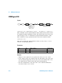
[SOURce:]PM:INTernal:FUNCtion
Syntax
SOUR :
PM
:INT
:FUNC
space
SIN
SQU
RAMP
NRAM
TRI
USER
?
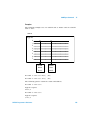
[SOURce:]PM:INTernal:FUNCtion {SINusoid|SQUare|RAMP|NRAMp|
TRIangle|USER}
This command sets the modulating waveform of the phase modulation. The
available modulating waveform types consist of sinusoid, square, ramp,
negative ramp, triangle, and user- defined.
[SOURce:]PM:INTernal:FUNCtion?
This query returns the selected modulating waveform as SIN, SQU, RAMP,
NRAM, TRI, or USER.
Parameter
74
Item
Type
Range of values
Default value
function
Discrete
SINusoid|SQUare|RAMP|NRAMp|TRIangle|
USER
SINusoid
U2761A Programmer’s Reference
Modulation Commands
6
Examples
The following command sets the modulating waveform to Sine.
PM:INT:FUNC SIN
The following query returns the modulating waveform.
PM:INT:FUNC?
Typical response:
SIN
U2761A Programmer’s Reference
75
6
Modulation Commands
[SOURce:]PM:INTernal:FREQuency
Syntax
SOUR :
PM
:INT
:FREQ
space
frequency
?
[SOURce:]PM:INTernal:FREQuency <frequency>
This command sets the frequency of the modulating waveform.
[SOURce:]PM:INTernal:FREQuency?
This query returns the modulating frequency in Hz.
Parameter
Item
Type
Range of values
Default value
frequency
Numeric
2 mHz to 20 kHz
10 Hz
Examples
This command sets the modulating frequency to 500 Hz.
PM:INT:FREQ 500
The following query returns the modulating frequency.
PM:INT:FREQ?
Typical response:
+5.0000000000000E+02
76
U2761A Programmer’s Reference
Modulation Commands
6
[SOURce:]PM:DEViation
Syntax
SOUR :
PM
:DEV
space
deviation in degrees
?
[SOURce:]PM:DEViation <deviation in degrees>
This command sets the phase deviation in degrees. The deviation setting
represents the peak variation in phase of the modulated waveform from
the carrier waveform.
[SOURce:]PM:DEViation?
This query returns the phase deviation in degrees.
Parameter
Item
Type
Range of values
Default value
deviation
Numeric
0 ° to 360 °
180 °
Examples
The following command sets the phase deviation to 10 °.
PM:DEV 10
The following query returns the phase deviation.
PM:DEV?
Typical response:
+1.0000000000000E+01
U2761A Programmer’s Reference
77
6
Modulation Commands
[SOURce:]PM:STATe
Syntax
SOUR :
PM
:STAT
space
0|OFF
1|ON
?
[SOURce:]PM:STATe {0|OFF|1|ON}
This command disables or enables the phase modulation.
[SOURce:]PM:STATe?
This query returns the phase modulation state as 0 if the modulation is
disabled, and 1 if the modulation is enabled.
Parameter
Item
Type
Range of values
Default value
state
Boolean
0|OFF|1|ON
0
Remark
The U2761A allows only one modulation mode to be enabled at a time,
and does not allow modulation when sweep is enabled.
Examples
The following command enables the phase modulation.
PM:STAT ON
The following query returns the modulation state.
PM:STAT?
Typical response:
1
78
U2761A Programmer’s Reference
Agilent U2761A USB Modular Function/Arbitrary Waveform Generator
Programmer’s Reference
7
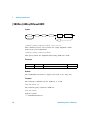
Shift Keying Commands
[SOURce:]ASKey:INTernal:RATE 80
[SOURce:]ASKey:STATe 81
[SOURce:]FSKey:FREQuency 82
[SOURce:]FSKey:INTernal:RATE 83
[SOURce:]FSKey:STATe 84
[SOURce:]PSKey:DEViation 85
[SOURce:]PSKey:INTernal:RATE 86
[SOURce:]PSKey:STATe 87
This section describes the Shift keying commands used to perform shift
keying modulations of the U2761A. These commands allow you to
configure the rate and modulation state for each shift keying modulation
type, as well as the frequency- shift keying “hop” frequency and
phase- shift keying deviation.
Agilent Technologies
79
7
Shift Keying Commands
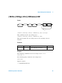
[SOURce:]ASKey:INTernal:RATE
Syntax
SOUR :
ASK
:INT
:RATE
space
rate in Hz
?
[SOURce:]ASKey:INTernal:RATE <rate in Hz>
This command sets the rate at which the output amplitude “shifts”
between two preset amplitudes.
[SOURce:]ASKey:INTernal:RATE?
This query returns the amplitude-shift keying (ASK) rate in Hz.
Parameter
Item
Type
Range of values
Default value
rate
Numeric
2 mHz to 100 kHz
10 Hz
Remark
The modulating waveform is a Square wave with a 50% duty cycle.
Examples
The following commands sets the ASK rate to 10 Hz.
ASK:INT:RATE 10
The following query returns the ASK rate.
ASK:INT:RATE?
Typical response:
+1.0000000000000E+01
80
U2761A Programmer’s Reference
Shift Keying Commands
7
[SOURce:]ASKey:STATe
Syntax
SOUR :
ASK
:STAT
space
0|OFF
1|ON
?
[SOURce:]ASKey:STATe {0|OFF|1|ON}
This command disables or enables the amplitude-shift keying (ASK)
modulation.
[SOURce:]ASKey:STATe?
This query returns the ASK modulation state as 0 if the modulation is
disabled, and 1 if the modulation is enabled.
Parameter
Item
Type
Range of values
Default value
state
Boolean
0|OFF|1|ON
0
Remark
The U2761A allows only one modulation mode to be enabled at a time,
and does not allow modulation when sweep is enabled.
Examples
The following command enables the ASK modulation.
ASK:STAT ON
The following query returns the modulation state.
ASK:STAT?
Typical response:
1
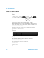
U2761A Programmer’s Reference
81
7
Shift Keying Commands
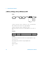
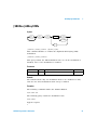
[SOURce:]FSKey:FREQuency
Syntax
SOUR :
FSK
:FREQ
space
frequency
?
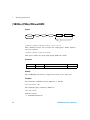
[SOURce:]FSKey:FREQuency <frequency>
This command sets the frequency-shift keying (FSK) alternate or “hop”
frequency.
[SOURce:]FSKey:FREQuency?
This query returns the “hop” frequency in Hz.
Parameter
Item
Type
Range of values
Default value
frequency
Numeric
• 1 μHz to 20 MHz (for sine and square)
• 1 μHz to 200 kHz (for ramp and arbitrary)
100 Hz
Examples
The following command sets the “hop” frequency to 200 Hz.
FSK:FREQ 200
The following query returns the “hop” frequency.
FSK:FREQ?
Typical response:
+2.0000000000000E+02
82
U2761A Programmer’s Reference
Shift Keying Commands
7
[SOURce:]FSKey:INTernal:RATE
Syntax
SOUR :
FSK
:INT
:RATE
space
rate in Hz
?
[SOURce:]FSKey:INTernal:RATE <rate in Hz>
The command sets the rate at which the output frequency “shifts” between
the carrier frequency and “hop” frequency.
[SOURce:]FSKey:INTernal:RATE?
This query returns the frequency-shift keying (FSK) rate in Hz.
Parameter
Item
Type
Range of values
Default value
rate
Numeric
2 mHz to 100 kHz
10 Hz
Remark
The modulating waveform is a Square wave with a 50% duty cycle.
Examples
The following command sets the FSK rate to 10 Hz.
FSK:INT:RATE 10
The following query returns the FSK rate.
FSK:INT:RATE?
Typical response:
+1.0000000000000E+01
U2761A Programmer’s Reference
83
7
Shift Keying Commands
[SOURce:]FSKey:STATe
Syntax
SOUR :
FSK
:STAT
space
0|OFF
1|ON
?
[SOURce:]FSKey:STATe {0|OFF|1|ON}
This command disables or enables the frequency-shift keying (FSK)
modulation.
[SOURce:]FSKey:STATe?
This query returns the FSK modulation state as 0 if the modulation is
disabled, and 1 if the modulation is enabled.
Parameter
Item
Type
Range of values
Default value
state
Boolean
0|OFF|1|ON
0
Remark
The U2761A allows only one modulation mode to be enabled at a time,
and does not allow modulation when sweep is enabled.
Examples
The following command enables the FSK modulation.
FSK:STAT ON
The following query returns the modulation state.
FSK:STAT?
Typical response:
1
84
U2761A Programmer’s Reference
Shift Keying Commands
7
[SOURce:]PSKey:DEViation
Syntax
SOUR :
PSK
:DEV
space
deviation in degrees
?
[SOURce:]PSKey:DEViation <deviation in degrees>
This command sets the phase-shift keying (PSK) deviation in degrees. The
deviation setting represents the phase variation of the shifted waveform
from the carrier waveform.
[SOURce:]PSKey:DEViation?
This query returns the PSK deviation in degrees.
Parameter
Item
Type
Range of values
Default value
deviation
Numeric
0 ° to 360 °
180 °
Examples
The following command sets the PSK deviation to 100 °.
PSK:DEV 100
The following query returns the PSK deviation.
PSK:DEV?
Typical response:
+1.0000000000000E+02
U2761A Programmer’s Reference
85
7
Shift Keying Commands
[SOURce:]PSKey:INTernal:RATE
Syntax
SOUR :
PSK
:INT
:RATE
space
rate in Hz
?
[SOURce:]PSKey:INTernal:RATE <rate in Hz>
This command sets the rate at which the output phase “shifts” between
two preset phases.
[SOURce:]PSKey:INTernal:RATE?
This query returns the phase-shift keying (PSK) rate in Hz.
Parameter
Item
Type
Range of values
Default value
rate
Numeric
2 mHz to 100 kHz
10 Hz
Remark
The modulating waveform is a Square wave with a 50% duty cycle.
Examples
The following commands sets the PSK rate to 100 Hz.
PSK:INT:RATE 100
The following query returns the PSK rate.
PSK:INT:RATE?
Typical response:
+1.0000000000000E+02
86
U2761A Programmer’s Reference
Shift Keying Commands
7
[SOURce:]PSKey:STATe
Syntax
SOUR :
PSK
:STAT
space
0|OFF
1|ON
?
[SOURce:]PSKey:STATe {0|OFF|1|ON}
This command disables or enables the phase-shift keying (PSK)
modulation.
[SOURce:]PSKey:STATe?
This query returns the PSK modulation state as 0 if the modulation is
disabled, and 1 if the modulation is enabled.
Parameter
Item
Type
Range of values
Default value
state
Boolean
0|OFF|1|ON
0
Remark
The U2761A allows only one modulation mode to be enabled at a time,
and does not allow modulation when sweep is enabled.
Examples
The following command enables the PSK modulation.
PSK:STAT ON
The following query returns the modulation state.
PSK:STAT?
Typical response:
1
U2761A Programmer’s Reference
87
7
88
Shift Keying Commands
U2761A Programmer’s Reference
Agilent U2761A USB Modular Function/Arbitrary Waveform Generator
Programmer’s Reference
8
Frequency Sweep Commands
[SOURce:]FREQuency:STARt 90
[SOURce:]FREQuency:STOP 91
[SOURce:]SWEep:SPACing 92
[SOURce:]SWEep:TIME 93
[SOURce:]SWEep:STATe 94
This section describes the Frequency sweep commands used to configure
the sweep settings of the U2761A. These commands allow you to set the
start and stop frequency values, sweep spacing, sweep time, and sweep
state.
Agilent Technologies
89
8
Frequency Sweep Commands
[SOURce:]FREQuency:STARt
Syntax
SOUR :
FREQ
:STAR
space
frequency
?
[SOURce:]FREQuency:STARt <frequency>
This command sets the start frequency.
[SOURce:]FREQuency:STARt?
This query returns the start frequency in Hz.
Parameter
Item
Type
Range of values
Default value
frequency
Numeric
• 1 μHz to 20 MHz (for sine and square)
• 1 μHz to 200 kHz (for ramp and arbitrary)
100 Hz
Examples
The following command sets the start frequency to 500 Hz.
FREQ:STAR 500
The following query returns the start frequency.
FREQ:STAR?
Typical response:
+5.0000000000000E+02
90
U2761A Programmer’s Reference
Frequency Sweep Commands
8
[SOURce:]FREQuency:STOP
Syntax
SOUR :
FREQ
:STOP
space
frequency
?
[SOURce:]FREQuency:STOP <frequency>
This command sets the stop frequency.
[SOURce:]FREQuency:STOP?
This query returns the stop frequency in Hz.
Parameter
Item
Type
Range of values
Default value
frequency
Numeric
• 1 μHz to 20 MHz (for sine and square)
• 1 μHz to 200 kHz (for ramp and arbitrary)
1 kHz
Examples
The following command sets the stop frequency to 10 kHz.
FREQ:STOP 10000
The following query returns the stop frequency.
FREQ:STOP?
Typical response:
+1.0000000000000E+04
U2761A Programmer’s Reference
91
8
Frequency Sweep Commands
[SOURce:]SWEep:SPACing
Syntax
SOUR :
SWE
:SPAC
space
LIN
LOG
?
[SOURce:]SWEep:SPACing {LINear|LOGarithmic}
This command sets either the linear or logarithmic spacing for the sweep.
[SOURce:]SWEep:SPACing?
This query returns the selected spacing as LIN or LOG.
Parameter
Item
Type
Range of values
Default value
spacing
Discrete
LINear or LOGarithmic
LINear
Examples
The following command sets the sweep spacing to linear.
SWE:SPAC LIN
The following query returns the spacing.
SWE:SPAC?
Typical response:
LIN
92
U2761A Programmer’s Reference
Frequency Sweep Commands
8
[SOURce:]SWEep:TIME
Syntax
SOUR :
SWE
:TIME
space
seconds
?
[SOURce:]SWEep:TIME <seconds>
This command sets the number of seconds required to sweep from the
start frequency to the stop frequency.
[SOURce:]SWEep:TIME?
This query returns the sweep time in seconds.
Parameter
Item
Type
Range of values
Default value
seconds
Numeric
1 ms to 500 s
1s
Remark
The number of discrete frequency points in the sweep is automatically
calculated by the U2761A and is based on the sweep time you have
selected.
Examples
The following command sets the sweep time to 20 s.
SWE:TIME 20
The following query returns the sweep time.
SWE:TIME?
Typical response:
+2.0000000000000E+01
U2761A Programmer’s Reference
93
8
Frequency Sweep Commands
[SOURce:]SWEep:STATe
Syntax
SOUR :
SWE
:STAT
space
0|OFF
1|ON
?
[SOURce:]SWEep:STATe {0|OFF|1|ON}
This command disables or enables the sweep mode.
[SOURce:]SWEep:STATe?
This query returns the sweep state as 0 if the sweep mode is disabled, or
1 if the sweep mode is enabled.
Parameter
Item
Type
Range of values
Default value
state
Boolean
0|OFF|1|ON
0
Remark
The U2761A does not allow the sweep mode to be enabled at the same
time that any modulation mode is enabled.
Examples
The following command enables the sweep mode.
SWE:STAT ON
The following query returns the sweep state.
SWE:STAT?
Typical response:
1
94
U2761A Programmer’s Reference
Agilent U2761A USB Modular Function/Arbitrary Waveform Generator
Programmer’s Reference
9
Triggering Commands
TRIGger[:SEQuence]:SOURce 96
TRIGger[:SEQuence][:IMMediate] 98
TRIGger[:SEQuence]:SLOPe 99
OUTPut:TRIGger:SLOPe 100
OUTPut:TRIGger[:STATe] 102
This section describes the Triggering commands used to control the trigger
functions of the U2761A. These commands allow you to configure the
trigger source, trigger slope, and trigger output state, as well as enable you
to trigger a sweep.
Agilent Technologies
95
9
Triggering Commands
TRIGger[:SEQuence]:SOURce
Syntax
TRIG
:SEQ
:SOUR
space
IMM
EXT
BUS
STRG
?
TRIGger[:SEQuence]:SOURce {IMMediate|EXTernal|BUS|STRG}
This command sets the source from which the U2761A will accept a
trigger.
• When the Immediate (internal) source is selected, the U2761A outputs
continuously when the sweep mode is enabled.
• When the External source is selected, the U2761A accepts a hardware
trigger applied to the Trig In connector. The U2761A initiates one sweep
each time Trig In receives a TTL pulse with the specified edge.
• When the Bus (software) source is selected, the U2761A initiates one
sweep each time a bus trigger command is received. You may send the
*TRG command to trigger the U2761A from the remote interface when
the Bus source is selected.
• Star trigger (STRG) is the synchronized trigger source from the U2781A
modular instrument chassis.
TRIGger[:SEQuence]:SOURce?
This query returns the selected trigger source as IMM, EXT, BUS, or STRG.
Parameter
96
Item
Type
Range of values
Default value
source
Discrete
IMMediate|EXTernal|BUS|STRG
IMMediate
U2761A Programmer’s Reference
Triggering Commands
9
Examples
The following command sets the trigger source to Immediate.
TRIG:SOUR IMM
The following query returns the trigger source.
TRIG:SOUR?
Typical response:
IMM
U2761A Programmer’s Reference
97
9
Triggering Commands
TRIGger[:SEQuence][:IMMediate]
Syntax
TRIG
:SEQ
:IMM
TRIGger[:SEQuence][:IMMediate]
This command triggers a sweep from the remote interface. This command
can be used with any of the available trigger sources.
Example
The following command triggers a sweep.
TRIG
98
U2761A Programmer’s Reference
Triggering Commands
9
TRIGger[:SEQuence]:SLOPe
Syntax
TRIG
:SEQ
:SLOP
space
POS
NEG
?
TRIGger[:SEQuence]:SLOPe {POSitive|NEGative}
This command sets the rising or falling edge for the trigger signal on the
Trig In connector to start the sweep.
TRIGger[:SEQuence]:SLOPe?
This query returns the selected trigger slope as POS or NEG.
Parameter
Item
Type
Range of values
Default value
slope
Discrete
POSitive|NEGative
POSitive
Examples
The following command sets the trigger slope to Positive.
TRIG:SLOP POS
The following query returns the trigger slope.
TRIG:SLOP?
Typical response:
POS
U2761A Programmer’s Reference
99
9
Triggering Commands
OUTPut:TRIGger:SLOPe
Syntax
OUTP
:TRIG
:SLOP
space
POS
NEG
?
OUTPut:TRIGger:SLOPe {POSitive|NEGative}
This command sets the rising or falling edge for the “trigger out” signal at
the beginning of the sweep. When enabled using the
OUTPut:TRIGger[:STATe] command, a TTL- compatible Square waveform
with the specified edge is output from the Trig Out connector at the
beginning of the sweep.
OUTPut:TRIGger:SLOPe?
This query returns the selected trigger slope as POS or NEG.
Parameter
Item
Type
Range of values
Default value
slope
Discrete
POSitive|NEGative
POSitive
Remarks
• When the Immediate (internal) trigger source is selected, the U2761A
outputs a Square waveform with a 50% duty cycle from the Trig Out
connector at the beginning of the sweep. The period of the waveform is
equal to the specified sweep time.
• When the Bus (software) trigger source is selected, the U2761A outputs
a pulse from the Trig Out connector at the beginning of each sweep.
100
U2761A Programmer’s Reference
Triggering Commands
9
Examples
The following command sets the trigger slope to Positive.
OUTP:TRIG:SLOP POS
The following query returns the trigger slope.
OUTP:TRIG:SLOP?
Typical response:
POS
U2761A Programmer’s Reference
101
9
Triggering Commands
OUTPut:TRIGger[:STATe]
Syntax
OUTP
:TRIG
:STAT
space
0|OFF
1|ON
?
OUTPut:TRIGger[:STATe] {0|OFF|1|ON}
This command disables or enables the “trigger out” signal on the Trig Out
connector. When enabled, a TTL- compatible Square waveform with the
specified edge is output from the Trig Out connector at the beginning of
the sweep.
OUTPut:TRIGger[:STATe]?
This query returns the trigger output state as 0 if the “trigger out” signal
is disabled, or 1 if the signal is enabled.
Parameter
Item
Type
Range of values
Default value
state
Boolean
0|OFF|1|ON
0
Examples
The following command enables the trigger output.
OUTP:TRIG ON
The following query returns the trigger output state.
OUTP:TRIG?
Typical response:
1
102
U2761A Programmer’s Reference
Agilent U2761A USB Modular Function/Arbitrary Waveform Generator
Programmer’s Reference
10
Arbitrary Waveform Commands
DATA:DAC VOLATILE 104
FORMat:BORDer 106
DATA:ATTRibute:AVERage? 107
DATA:ATTRibute:CFACtor? 108
DATA:ATTRibute:POINts? 109
DATA:ATTRibute:PTPeak? 110
This section describes the Arbitrary waveform commands used to
configure the user- defined Arbitrary waveforms for the U2761A. These
commands allow you to download the arbitrary data and configure the
byte order format. You may also query the number of points as well as the
average, crest factor, and peak- to- peak values of the data points. Use the
FUNC USER or APPL:USER command to output an Arbitrary waveform.
Agilent Technologies
103
10
Arbitrary Waveform Commands
DATA:DAC VOLATILE
Syntax
DATA
:DAC
VOLATILE
,
space
binary block
value , value , ...
DATA:DAC VOLATILE, {<binary block>|<value>, <value>, . . . }
This command downloads the arbitrary data in binary block or decimal
integer values from –8191 to +8191 into volatile memory. You can
download from 1 point (a DC signal) to 65536 (64K) points per waveform
in IEEE- 488.2 binary block format or as a list of values. The range of
values corresponds to the values available using internal 14- bit
Digital- to- Analog Converter (DAC) codes. The U2761A takes the specified
number of points and expands them to fill up the waveform memory.
Parameter
Item
Type
Range of values
Default value
value
Numeric
–8191 to +8191
0
Remarks
• The values of –8191 and +8191 correspond to the peak values of the
waveform (if the offset is 0 V).
• The maximum amplitude will be limited if the data points do not span
the full range of values between ±8191.
• The DATA:DAC command overwrites the previous waveform in volatile
memory (and no error will be generated).
104
U2761A Programmer’s Reference
Arbitrary Waveform Commands
10
• In the IEEE- 488.2 binary block format, a block header precedes the
waveform data. The block header has the following format:
#
Start of
data block
5
32768
Number of digits
to follow
Even number of bytes to follow
(32768 bytes = 16384 points)
The U2761A represents binary data as 16- bit integers, which are sent as
two bytes. Therefore, the total number of bytes is always twice the
number of data points in the waveform (and must always be an even
number). For example, 32768 bytes are required to download a waveform
with 16384 points.
Use the FORMat:BORDer command to select the byte order for binary
data. If you specify FORM:BORD NORM (default), the most- significant byte
(MSB) of each data point is assumed first. If you specify
FORM:BORD SWAP, the least- significant byte (LSB) of each data point is
assumed first.
Examples
The following command downloads seven integer points using the binary
block format.
DATA:DAC VOLATILE, #214
Binary Data
The following command downloads four integer points in decimal format.
DATA:DAC VOLATILE, –8191, 0, 8191, 0
U2761A Programmer’s Reference
105
10
Arbitrary Waveform Commands
FORMat:BORDer
Syntax
FORM
:BORD
space
NORM
SWAP
?
FORMat:BORDer {NORMal|SWAPped}
This command sets the byte order format for binary block downloads. For
the Normal byte order, the most significant byte (MSB) of each data point
is assumed first. For the Swapped byte order, the least significant byte
(LSB) of each data point is assumed first.
FORMat:BORDer?
This query returns the selected byte order format as NORM or SWAP.
Parameter
Item
Type
Range of values
Default value
format
Discrete
NORMal|SWAPped
NORMal
Examples
The following command sets the Normal byte order.
FORM:BORD NORM
The following query returns the byte order format.
FORM:BORD?
Typical response:
NORM
106
U2761A Programmer’s Reference
Arbitrary Waveform Commands
10
DATA:ATTRibute:AVERage?
Syntax
DATA
:ATTR
:AVER
?
DATA:ATTRibute:AVERage?
This query returns the arithmetic average of all data points for the
Arbitrary waveform.
Example
The following query returns the average of the data points.
DATA:ATTR:AVER?
Typical response:
+0.0000000000000E+00
U2761A Programmer’s Reference
107
10
Arbitrary Waveform Commands
DATA:ATTRibute:CFACtor?
Syntax
DATA
:ATTR
:CFAC
?
DATA:ATTRibute:CFACtor?
This query returns the crest factor of all data points for the Arbitrary
waveform.
Remarks
Crest factor is the ratio of a signal peak value to its RMS value and will
differ according to waveshape. The crest factor can be computed as
follows:
Crest factor = Vpeak / Vrms
The typical crest factor values for several common waveforms are stated
in the following table:
Waveform
Crest factor
Sine
1.414
Triangle
1.732
Square
1
DC
1
Example
The following query returns the crest factor of the data points. (Assuming
that the Arbitrary waveform used has a sine waveshape).
DATA:ATTR:CFAC?
Typical response:
+1.4142140000000E+00
108
U2761A Programmer’s Reference
Arbitrary Waveform Commands
10
DATA:ATTRibute:POINts?
Syntax
DATA
:ATTR
:POIN
?
DATA:ATTRibute:POINts?
This query returns the number of points for the Arbitrary waveform from
1 to 65536 points.
Example
The following query returns the points for the Arbitrary waveform.
DATA:ATTR:POIN?
Typical response:
+4.0000000000000E+00
U2761A Programmer’s Reference
109
10
Arbitrary Waveform Commands
DATA:ATTRibute:PTPeak?
Syntax
DATA
:ATTR
:PTP
?
DATA:ATTRibute:PTPeak?
This query returns the peak-to-peak value of all data points for the
Arbitrary waveform from “0” to “16382”, with “16382” indicating full
amplitude available.
Example
The following query returns the peak- to- peak value of the data points.
DATA:ATTR:PTP?
Typical response:
+1.6382000000000E+04
110
U2761A Programmer’s Reference
Agilent U2761A USB Modular Function/Arbitrary Waveform Generator
Programmer’s Reference
11
SYSTem Commands
SYSTem:CDEScription? 112
SYSTem:ERRor? 113
SYSTem:VERSion? 114
This section provides the system- related information such as error
conditions and chassis identity. This information is not directly related to
waveform generation but is an important part of the U2761A system.
Agilent Technologies
111
11
SYSTem Commands
SYSTem:CDEScription?
Syntax
SYST
:CDES
?
SYSTem:CDEScription?
This query identifies which slot and chassis that the U2761A is plugged
into the U2781A modular instrument chassis, and returns the slot and
chassis number respectively.
Remarks
• If the U2761A is in standalone mode, then this query would return
+7,+0.
• Refer to the U2781A Modular Instrument Chassis User's Guide for
details.
Example
The following query returns the slot and chassis number (assuming that
the U2761A is slotted into slot 5 of chassis #12).
SYST:CDES?
Typical response:
+5,+12
112
U2761A Programmer’s Reference
SYSTem Commands
11
SYSTem:ERRor?
Syntax
SYST
:ERR
?
SYSTem:ERRor?
This query returns the next error number and its corresponding message
string from the error queue. The queue is a first-in, first-out (FIFO) buffer
that stores errors as they occur. Errors are cleared as you read them.
Remarks
• If more than 20 errors have occurred, the last error stored in the queue
(the most recent error) is replaced with –350,"Queue overflow".
• If no errors have occurred when you read the error queue, the U2761A
responds with +0,"No error".
• The error queue is cleared by the clear status (*CLS) command or when
power is cycled. The errors are also cleared when you read the queue.
• Refer to Chapter 16, “Error Messages” on page 141 for the error
messages.
Example
The following query reads and clears one error.
SYST:ERR?
Typical response:
–101,"Invalid character"
U2761A Programmer’s Reference
113
11
SYSTem Commands
SYSTem:VERSion?
Syntax
SYST
:VERS
?
SYSTem:VERSion?
This query returns the SCPI standard version with which the U2761A is in
compliance. The response format is in the form of YYYY.V, where YYYY
represents the year of the version and V represents the version number
for that year.
Example
The following query returns the SCPI version.
SYST:VERS?
Typical response:
1997.0
114
U2761A Programmer’s Reference
Agilent U2761A USB Modular Function/Arbitrary Waveform Generator
Programmer’s Reference
12
Phase-Lock Commands
[SOURce:]PHASe:SOURce 116
[SOURce:]PHASe[:ADJust] 117
UNIT:ANGLe 118
[SOURce:]PHASe:REFerence 119
[SOURce:]PHASe:UNLock:ERRor[:STATe] 120
OUTPut:PHASe[:STATe] 121
This section describes the Phase-lock commands used to configure the
phase- lock settings of the U2761A. These commands allow you to set the
phase source, phase offset and unit, zero- phase reference point,
phase- lock error state, and phase output state.
Agilent Technologies
115
12
Phase-Lock Commands
[SOURce:]PHASe:SOURce
Syntax
SOUR :
PHAS
:SOUR
space
INT
EXT
CCG
?
[SOURce:]PHASe:SOURce {INTernal|EXTernal|CCG}
This command sets the phase source to synchronize the output waveform.
Chassis reference clock (CCG) is the synchronized phase source from the
U2781A modular instrument chassis.
[SOURce:]PHASe:SOURce?
This query returns the selected phase source as INT, EXT, or CCG.
Parameter
Item
Type
Range of values
Default value
source
Discrete
INTernal|EXTernal|CCG
INTernal
Examples
The following command sets the phase source to Internal.
PHAS:SOUR INT
The following query returns the phase source.
PHAS:SOUR?
Typical response:
INT
116
U2761A Programmer’s Reference
Phase-Lock Commands
12
[SOURce:]PHASe[:ADJust]
Syntax
SOUR :
PHAS
:ADJ
space
angle
?
[SOURce:]PHASe[:ADJust] <angle>
This command adjusts the phase offset of the output waveform in degrees
or radians as specified by the UNIT:ANGLe command.
[SOURce:]PHASe[:ADJust]?
This query returns the adjusted phase offset in the specified unit.
Parameter
Item
Type
Range of values
Default value
angle
Numeric
• –360 ° to 360 ° (for degrees)
• –2 p to 2 p (for radians)
0°
Examples
The following command sets the phase offset to 180 °.
PHAS 180
The following query returns the phase offset.
PHAS?
Typical response:
+1.8000000000000E+02
U2761A Programmer’s Reference
117
12
Phase-Lock Commands
UNIT:ANGLe
Syntax
UNIT
:ANGL
space
DEG
RAD
?
UNIT:ANGLe {DEGree|RADian}
This command sets either degrees or radians for the phase offset value.
UNIT:ANGLe?
This query returns the selected unit as DEG or RAD.
Parameter
Item
Type
Range of values
Default value
unit
Discrete
DEGree|RADian
DEGree
Examples
The following command sets the phase offset unit to degrees.
UNIT:ANGL DEG
The following query returns the phase offset unit.
UNIT:ANGL?
Typical response:
DEG
118
U2761A Programmer’s Reference
Phase-Lock Commands
12
[SOURce:]PHASe:REFerence
Syntax
SOUR :
PHAS
:REF
[SOURce:]PHASe:REFerence
This command immediately sets the zero-phase reference point without
changing the output of the U2761A. This command resets the phase offset
value returned by the [SOURce:]PHASe[:ADJust] command but does not
affect the output waveform.
Example
The following command sets the zero-phase reference point.
PHAS:REF
U2761A Programmer’s Reference
119
12
Phase-Lock Commands
[SOURce:]PHASe:UNLock:ERRor[:STATe]
Syntax
SOUR :
PHAS
:UNL
:ERR
:STAT
space
0|OFF
1|ON
?
[SOURce:]PHASe:UNLock:ERRor[:STATe] {0|OFF|1|ON}
This command disables or enables the U2761A to generate an error if the
phase-lock is ever lost.
[SOURce:]PHASe:UNLock:ERRor[:STATe]?
This query returns the phase-lock error state as 0 if disabled, or 1 if
enabled.
Parameter
Item
Type
Range of values
Default value
state
Boolean
0|OFF|1|ON
0
Examples
The following command enables the phase- lock error state.
PHAS:UNL:ERR ON
The following query returns the phase- lock error state.
PHAS:UNL:ERR?
Typical response:
1
120
U2761A Programmer’s Reference
Phase-Lock Commands
12
OUTPut:PHASe[:STATe]
Syntax
OUTP
:PHAS
:STAT
space
0|OFF
1|ON
?
OUTPut:PHASe[:STATe] {0|OFF|1|ON}
This command disables or enables the 10 MHz reference phase output.
OUTPut:PHASe[:STATe]?
This query returns the phase output state as 0 if the output is disabled,
or 1 if the output is enabled.
Parameter
Item
Type
Range of values
Default value
state
Boolean
0|OFF|1|ON
0
Examples
The following command enables the phase output.
OUTP:PHAS ON
The following query returns the phase output state.
OUTP:PHAS?
Typical response:
1
U2761A Programmer’s Reference
121
12
122
Phase-Lock Commands
U2761A Programmer’s Reference
Agilent U2761A USB Modular Function/Arbitrary Waveform Generator
Programmer’s Reference
13
Status Reporting Commands
STATus:PRESet 124
STATus:QUEStionable:CONDition? 125
STATus:QUEStionable:ENABle 126
STATus:QUEStionable[:EVENt]? 128
This section describes the Status reporting commands used to determine
the operating condition of the U2761A at any time. Refer to Chapter 1,
“SCPI Status System” on page 11 for more information on the status
registers.
Agilent Technologies
123
13
Status Reporting Commands
STATus:PRESet
Syntax
STAT
:PRES
STATus:PRESet
This command clears all bits in the Questionable Data enable register.
Example
The following command presets the Questionable enable register.
STAT:PRES
124
U2761A Programmer’s Reference
Status Reporting Commands
13
STATus:QUEStionable:CONDition?
Syntax
STAT
:QUES
:COND
?
STATus:QUEStionable:CONDition?
This query returns the binary-weighted sum of all bits set in the
Questionable Data condition register. The condition register is a read-only
register, which holds the live (unlatched) questionable status of the
instrument. The bits are not cleared when you read the register.
Remarks
For more information on the Questionable condition register, refer to
Chapter 1, “Status system diagram” on page 12. The bit definitions for the
Questionable Data register are listed in “Questionable Data register” on
page 13.
Example
The following query reads the Questionable condition register.
STAT:QUES:COND?
Typical response:
+544
U2761A Programmer’s Reference
125
13
Status Reporting Commands
STATus:QUEStionable:ENABle
Syntax
STAT
:QUES
:ENAB
space
value
STATus:QUEStionable:ENABle <value>
This command enables the bits in the Questionable Data enable register.
The selected bits are then reported to the Status Byte register. The enable
register is a mask for enabling specific bits from the Questionable event
register to set the questionable summary bit (QUES) of the Status Byte
register. This bit (bit 3) is the logical OR of all the Questionable event
register bits that are enabled by the Questionable enable register.
STATus:QUEStionable:ENABle?
This query returns the binary-weighted sum of all bits set in the enable
register.
Parameter
Item
Type
Range of values
Default value
value
Numeric
A decimal value which corresponds to the
binary-weighted sum of the bits in the register
0
Remarks
• The STATus:PRESet command will clear all bits in the enable register.
• For more information on the Questionable enable register, refer to
Chapter 1, “Status system diagram” on page 12. The bit definitions for
the Questionable Data register are listed in “Questionable Data
register” on page 13.
126
U2761A Programmer’s Reference
Status Reporting Commands
13
Examples
The following command enables bit 4 (decimal value = 16) in the enable
register.
STAT:QUES:ENAB 16
The following query returns the bit enabled in the register.
STAT:QUES:ENAB?
Typical response:
+16
U2761A Programmer’s Reference
127
13
Status Reporting Commands
STATus:QUEStionable[:EVENt]?
Syntax
STAT
:QUES
:EVEN
?
STATus:QUEStionable[:EVENt]?
This query returns the binary-weighted sum of all bits set in the
Questionable Data event register. This is a read- only register and the bits
are cleared when you read the register.
Remarks
• Once a bit is set, it remains set until cleared by reading the event
register or the clear status (*CLS) command.
• For more information on the Questionable event register, refer to
Chapter 1, “Status system diagram” on page 12. The bit definitions for
the Questionable Data register are listed in “Questionable Data
register” on page 13.
Example
The following query reads the Questionable event register.
STAT:QUES?
Typical response:
+512
128
U2761A Programmer’s Reference
Agilent U2761A USB Modular Function/Arbitrary Waveform Generator
Programmer’s Reference
14
CALibration Commands
CALibration:SECure:STATe 130
CALibration:SECure:CODE 131
CALibration:SETup 132
CALibration:VALue 133
CALibration:COUNt? 134
CALibration:STRing 135
This section describes the Calibration commands used to configure the
calibration settings for the U2761A. These commands allow you to set the
calibration security state, change the security code, set the calibration
setup number and calibration value, query the calibration count, and store
a calibration message.
Agilent Technologies
129
14
CALibration Commands
CALibration:SECure:STATe
Syntax
CAL
:SEC
:STAT
space
OFF
,
code
ON
RESET
CALibration:SECure:STATe {OFF|ON|RESET}, <code>
This command unsecures or secures the U2761A for calibration. If you
forget your security code, you can reset the code by specifying U2761A.
CALibration:SECure:STATe?
This query returns the security state as 0 (OFF) if the U2761A is
unsecured, or 1 (ON) if secured.
Parameters
Item
Type
Range of values
Default value
state
Discrete
OFF|ON|RESET
ON
code
Numeric
Up to 12 alphanumeric characters
U2761A
Examples
The following command secures the U2761A for calibration.
CAL:SEC:STAT ON, U2761A
The following query returns the security state.
CAL:SEC:STAT?
Typical response:
1
130
U2761A Programmer’s Reference
CALibration Commands
14
CALibration:SECure:CODE
Syntax
CAL
:SEC
:CODE
space
new code
CALibration:SECure:CODE <new code>
This command inputs a new security code. To change the security code,
you must first unsecure the U2761A using the old security code, and then
enter a new code. The security code is stored in nonvolatile memory.
Parameter
Item
Type
Range of values
Default value
code
String
Up to 12 alphanumeric characters
U2761A
Remark
The first character of the code must always be a letter (A to Z).
Example
The following command renews the security code of the U2761A.
CAL:SEC:CODE U2761A
U2761A Programmer’s Reference
131
14
CALibration Commands
CALibration:SETup
Syntax
CAL
:SET
space
1
2
3
...
115
?
CALibration:SETup <1|2|3| . . . |115>
This command configures the U2761A internal state for each of the
calibration steps to be performed. Before any calibration step is performed
for the U2761A, the default setup is 0.
CALibration:SETup?
This query reads the calibration setup number and returns a value from 1
to 115.
Parameter
Item
Type
Range of values
Default value
setup number
Numeric
1 to 115
0
Examples
The following command sets the U2761A calibration setup number to 5.
CAL:SET 5
The following query returns the calibration setup number.
CAL:SET?
Typical response:
+5
132
U2761A Programmer’s Reference
CALibration Commands
14
CALibration:VALue
Syntax
CAL
:VAL
space
value
?
CALibration:VALue <value>
This command specifies the measured value of the known calibration
signal depending on the calibration steps.
CALibration:VALue?
This query returns the calibration value.
NOTE
Refer to the Agilent U2761A USB Modular Function/Arbitrary Waveform Generator Service
Guide for the range of values of each calibration step.
Examples
The following command sets the value to 1×10⁷.
CAL:VAL 1E+7
The following query returns the calibration value.
CAL:VAL?
Typical response:
+1.0000000000000E+07
U2761A Programmer’s Reference
133
14
CALibration Commands
CALibration:COUNt?
Syntax
CAL
:COUN
?
CALibration:COUNt?
This query determines the number of times the U2761A has been
calibrated, where the count number is incremented by one for each
calibration step. The calibration count is stored in nonvolatile memory.
NOTE
Ensure that your U2761A has been calibrated before it leaves the factory. When you receive
your U2761A from the factory, be sure to read the count to determine its initial value.
Example
The following query returns the calibration count for the U2761A.
CAL:COUN?
Typical response:
+115
134
U2761A Programmer’s Reference
CALibration Commands
14
CALibration:STRing
Syntax
CAL
:STR
space
quoted string
?
CALibration:STRing <quoted string>
This command stores a message in nonvolatile calibration memory. Storing
a message will overwrite any message previously stored in memory.
CALibration:STRing?
This query reads the calibration message and returns a quoted string.
Parameter
Item
Type
Range of values
Default value
string
String
Up to 40 alphanumeric characters
N/A
Examples
The following command stores the calibration message.
CAL:STR '01 JAN 2008:CALIBRATED'
The following query returns the quoted string.
CAL:STR?
Typical response:
''01 JAN 2008:CALIBRATED''
U2761A Programmer’s Reference
135
14
136
CALibration Commands
U2761A Programmer’s Reference
Agilent U2761A USB Modular Function/Arbitrary Waveform Generator
Programmer’s Reference
15
CONFigure Command
CONFigure:SSI 138
The CONFigure:SSI command handles the synchronization status when
the U2761A is used in the U2781A modular instrument chassis.
Agilent Technologies
137
15
CONFigure Command
CONFigure:SSI
Syntax
CONF
:SSI
space
NONE
,
(
@address
,
address
)
MAST
SLAV
CONFigure:SSI {NONE|MASTer|SLAVe}, (@<address>[,<address>])
This command sets the synchronization status (master/slave) when used in
the U2781A modular instrument chassis. The master/slave mode forces the
U2761A trigger source to Simultaneous Synchronization Interface (SSI).
This command is only operational when used in the U2781A chassis.
CONFigure:SSI?
This query returns the synchronization status as NONE, MAST, or SLAV,
and the corresponding address.
Parameters
Item
Type
Range of values
Default value
mode
Discrete
NONE|MASTer|SLAVe
NONE
address
Numeric
0 to 7
0
Remarks
• Address is not required to be specified for CONFigure:SSI NONE.
• In the master mode, the U2761A sends the SSI signal to the slave unit
via the U2781A trigger bus. In the slave mode, the U2761A will receive
the signal from the master unit and begin synchronization.
• For more information on the SSI, refer to the U2781A USB Modular
Instrument Chassis User’s Guide.
138
U2761A Programmer’s Reference
CONFigure Command
15
Examples
The following example sets one U2761A unit to master and one U2761A
unit to slave.
U2781A
Trigger bus
0
1
2
3
4
5
6
7
U2761A
Master
U2761A
Slave
(Unit 1)
(Unit 2)
For Unit 1: CONF:SSI MAST, (@0)
For Unit 2: CONF:SSI SLAV, (@0)
The following queries return the status and address.
For Unit 1: CONF:SSI?
Typical response:
MAST,0
For Unit 2: CONF:SSI?
Typical response:
SLAV,0
U2761A Programmer’s Reference
139
15
140
CONFigure Command
U2761A Programmer’s Reference
Agilent U2761A USB Modular Function/Arbitrary Waveform Generator
Programmer’s Reference
16
Error Messages
Error Messages 142
Command errors 142
Execution errors 144
Device-dependent errors 151
Query errors 152
Instrument errors 152
Self-test errors 153
Calibration errors 153
Arbitrary waveform errors 155
The U2761A SCPI command errors are summarized in this chapter.
Agilent Technologies
141
16
Error Messages
Error Messages
Error messages are created once an erroneous condition has been
detected.
• Errors are retrieved in first- in- first- out (FIFO) order using the
SYSTem:ERRor? command. The first error returned is the first error
that was stored. Errors are cleared as you retrieve them.
• If more than 20 errors have occurred, the last error stored in the queue
(the most recent error) is replaced with –350,"Queue overflow". No
additional errors are stored until you remove errors from the queue. If
no errors have occurred when you read the error queue, the U2761A
responds with +0,"No error".
• The error queue is also cleared by the clear status (*CLS) command or
when power is cycled. The error queue is not cleared by an instrument
reset (*RST) command.
Command errors
The following table shows the list of command errors.
Table 16-1 Command errors
Error number
Command errors
–101
Invalid character
An invalid character was found in the command string. You may have inserted a character such as #, $, or
% in a command keyword or within a parameter.
–102
Syntax error
Invalid syntax was found in the command string. You may have inserted a blank space before or after a
colon in the command header, or before a comma.
–103
Invalid separator
An invalid separator was found in the command string. Check for proper usage of , ; :
–105
GET not allowed
A Group Execute Trigger (GET) is not allowed within a command string.
142
U2761A Programmer’s Reference
Error Messages
16
Table 16-1 Command errors (continued)
–108
Parameter not allowed
More parameters were received than were expected for the command. You may have entered an extra
parameter or added a parameter to a command that does not require a parameter.
–109
Missing parameter
Fewer parameters were received than were expected for this command. You have omitted one or more
parameters that are required for this command.
–112
Program mnemonic too long
A command header was received which contained more than the maximum 12 characters allowed. This
error is also reported when a character-type parameter is too long.
–113
Undefined header
A command was received that is not valid. You may have misspelled the command or it may not be a valid
command. If you are using the short form of the command, remember that it may contain up to four letters.
–121
Invalid character in number
An invalid character was found in the number specified for a parameter value
–123
Exponent too large
A numeric parameter was found where its exponent was larger than 32759
–124
Too many digits
The mantissa of a numeric parameter contained more than 255 digits, excluding leading zeros
–128
Numeric data not allowed
A numeric parameter was received but a character string was expected
–131
Invalid suffix
A suffix was incorrectly specified for a numeric parameter
–134
Suffix too long
The suffix contains more than 12 characters
–138
Suffix not allowed
A suffix is not supported for this command
–148
Character data not allowed
A discrete parameter was received, but a string or numeric parameter was expected
–151
Invalid string data
An invalid character string was received. Check that the string is enclosed in quotation marks.
U2761A Programmer’s Reference
143
16
Error Messages
Table 16-1 Command errors (continued)
–158
String data not allowed
A character string was received, but is not allowed for this command
–161
Invalid block data
The number of data bytes sent does not match the number of bytes specified in the header
–168
Block data not allowed
Data was sent in the arbitrary block format but is not allowed for this command
–170 to –178
Expression errors
The U2761A does not accept mathematical expressions
Execution errors
The execution errors are listed in the table below.
Table 16-2 Execution errors
Error number
Execution errors
–211
Trigger ignored
A Group Execute Trigger (GET) or *TRG was received but the trigger was ignored
–223
Too much data
An Arbitrary waveform was specified that contains more than 65536 waveform points
–224
Illegal parameter value
An exact value was expected or an invalid discrete parameter was received
–221
Settings conflict; frequency reduced for ramp function
When you change to the ramp function (output frequency limit is 200 kHz) from a function that allows a
higher frequency, the U2761A will automatically adjust the frequency to 200 kHz
–221
Settings conflict; frequency reduced for pulse function
When you change to the pulse function (output frequency limit is 5 MHz) from a function that allows a
higher frequency, the U2761A will automatically adjust the frequency to 5 MHz
144
U2761A Programmer’s Reference
Error Messages
16
Table 16-2 Execution errors (continued)
–221
Settings conflict; frequency reduced for user function
When you change to the arbitrary function (output frequency limit is 200 kHz) from a function that allows
a higher frequency, the U2761A will automatically adjust the frequency to 200 kHz
–221
Settings conflict; frequency forced duty cycle change
If the Square wave function is selected and you change to a frequency that cannot produce the current
duty cycle, the duty cycle is automatically adjusted to the maximum value for the new frequency
–221
Settings conflict; frequency changed due to FM deviation
If the carrier frequency is lower than the minimum FM deviation plus 1 μHz, the carrier frequency will be
adjusted to the minimum value allowed
–221
Settings conflict; amplitude changed due to offset
If the existing output amplitude is not valid, the U2761A will automatically adjust it to the maximum value
allowed with the offset voltage specified
–221
Settings conflict; amplitude changed due to function
The amplitude limits are determined by the currently selected output units when the units are Vrms or
dBm due to the differences in crest factor for the various output functions
–221
Settings conflict; amplitude units change to Vpp due to high-Z load
The output units cannot be set to dBm if the output termination is currently set to “high impedance”
–221
Settings conflict; offset changed due to amplitude
If the existing offset voltage is not valid, the U2761A will automatically adjust it to the maximum DC
voltage allowed with the amplitude specified
–221
Settings conflict; offset changed due to arbitrary span
If the existing offset voltage is not valid, the U2761A will automatically adjust it to the maximum DC
voltage allowed with the arbitrary span on differences in crest factor
–221
Settings conflict; offset changed on exit from dc function
When you select a different function other than DC, the U2761A will adjust the offset voltage as needed to
be compatible with the current amplitude setting
–221
Settings conflict; low level changed due to high level
If you specify a high level that is less than the existing low level, the U2761A will automatically set the low
level to the minimum value allowed lower than the high level
–221
Settings conflict; high level changed due to low level
If you specify a low level that is greater than the existing high level, the U2761A will automatically set the
high level to the minimum value allowed greater than the low level
U2761A Programmer’s Reference
145
16
Error Messages
Table 16-2 Execution errors (continued)
–221
Settings conflict; pulse width increased due to large period
The U2761A has adjusted the pulse width to the new minimum determined by the current period
–221
Settings conflict; pulse width decreased due to period
The U2761A has decreased the pulse width to accommodate the specified period
–221
Settings conflict; FSK hopping frequency changed due to function
The FSK hopping frequency is greater than the maximum frequency of the switched function
–221
Settings conflict; not able to set amplitude level for dc function
The U2761A is unable to generate an amplitude level for the DC function
–221
Settings conflict; not able to modulate pulse, modulation is turned off
The U2761A cannot generate a modulated waveform using the pulse function. The selected modulation
mode has been turned off.
–221
Settings conflict; not able to modulate dc, modulation turned off
The U2761A cannot generate a modulated waveform using the DC voltage function. The selected
modulation mode has been turned off.
–221
Settings conflict; not able to sweep pulse, sweep is turned off
The U2761A cannot generate a sweep using the pulse function. The sweep mode has been turned off.
–221
Settings conflict; not able to sweep dc, sweep turned off
The U2761A cannot generate a sweep using the DC voltage function. The sweep mode has been turned
off.
–221
Settings conflict; AM turned off by selection of other mode or modulation
The U2761A will allow only one modulation or sweep mode to be enabled at the same time
–221
Settings conflict; FM turned off by selection of other mode or modulation
The U2761A will allow only one modulation or sweep mode to be enabled at the same time
–221
Settings conflict; PM turned off by selection of other mode or modulation
The U2761A will allow only one modulation or sweep mode to be enabled at the same time
–221
Settings conflict; ASK turned off by selection of other mode or modulation
The U2761A will allow only one modulation or sweep mode to be enabled at the same time
–221
Settings conflict; FSK turned off by selection of other mode or modulation
The U2761A will allow only one modulation or sweep mode to be enabled at the same time
146
U2761A Programmer’s Reference
Error Messages
16
Table 16-2 Execution errors (continued)
–221
Settings conflict; PSK turned off by selection of other mode or modulation
The U2761A will allow only one modulation or sweep mode to be enabled at the same time
–221
Settings conflict; sweep turned off by selection of other mode or modulation
The U2761A will allow only one modulation or sweep mode to be enabled at the same time
–221
Settings conflict; 10MHz reference connector used by phase output
If you have enabled the output 10 MHz reference signal, the U2761A automatically disables the external
phase source. The 10 MHz reference connector cannot be used for both operations at the same time.
–221
Settings conflict; phase output disabled by phase external
When the external phase source is selected, the output 10 MHz reference signal cannot be enabled. The
10 MHz reference connector cannot be used for both operations at the same time.
–222
Data out of range; sine frequency; value clipped to upper limit
The waveform frequency has been limited to an upper boundary due to the selection of the Sine waveform
function
–222
Data out of range; square frequency; value clipped to upper limit
The waveform frequency has been limited to an upper boundary due to the selection of the Square
waveform function
–222
Data out of range; user frequency; value clipped to upper limit
The waveform frequency has been limited to an upper boundary due to the selection of the Arbitrary
waveform function
–222
Data out of range; pulse frequency; value clipped to upper limit
The waveform frequency has been limited to an upper boundary due to the selection of the Pulse
waveform function
–222
Data out of range; ramp frequency; value clipped to upper limit
The waveform frequency has been limited to an upper boundary due to the selection of the Ramp
waveform function
–222
Data out of range; frequency; value clipped to lower limit
The waveform frequency has been limited to a lower boundary
–222
Data out of range; frequency; value clipped to upper limit
The waveform frequency has been limited to an upper boundary
–222
Data out of range; amplitude; value clipped to lower limit
The waveform amplitude has been limited to a lower boundary
U2761A Programmer’s Reference
147
16
Error Messages
Table 16-2 Execution errors (continued)
–222
Data out of range; amplitude; value clipped to upper limit
The waveform amplitude has been limited to an upper boundary
–222
Data out of range; offset; value clipped to lower limit
The offset voltage has been limited to a lower boundary
–222
Data out of range; offset; value clipped to upper limit
The offset voltage has been limited to an upper boundary
–222
Data out of range; HIGH value; value clipped to lower limit
The high voltage has been limited to a lower boundary
–222
Data out of range; HIGH value; value clipped to upper limit
The high voltage has been limited to an upper boundary
–222
Data out of range; LOW value; value clipped to lower limit
The low voltage has been limited to a lower boundary
–222
Data out of range; LOW value; value clipped to upper limit
The low voltage has been limited to an upper boundary
–222
Data out of range; duty cycle; value clipped to lower limit
The Square wave duty cycle is limited to 20% by the U2761A hardware
–222
Data out of range; duty cycle; value clipped to upper limit
The Square wave duty cycle is limited to 80% by the U2761A hardware
–222
Data out of range; duty cycle limited by frequency; value clipped to lower limit
The Square wave duty cycle is limited to 40% when the frequency is greater than 10 MHz
–222
Data out of range; duty cycle limited by frequency; value clipped to upper limit
The Square wave duty cycle is limited to 60% when the frequency is greater than 10 MHz
–222
Data out of range; ramp symmetry; value clipped to lower limit
The ramp symmetry is limited to a lower boundary of 0.0% by the U2761A hardware
–222
Data out of range; ramp symmetry; value clipped to upper limit
The ramp symmetry is limited to an upper boundary of 100.0% by the U2761A hardware
–222
Data out of range; load; value clipped to lower limit
The output load is limited to a lower boundary of 1 Ω by the U2761A hardware
148
U2761A Programmer’s Reference
Error Messages
16
Table 16-2 Execution errors (continued)
–222
Data out of range; load; value clipped to upper limit
The output load is limited to an upper boundary of 10 kΩ by the U2761A hardware
–222
Data out of range; pulse period; value clipped to lower limit
The pulse period has been limited to a lower boundary
–222
Data out of range; pulse period; value clipped to upper limit
The pulse period has been limited to an upper boundary
–222
Data out of range; pulse width; value clipped to lower limit
The desired pulse width is limited to a lower boundary by the U2761A hardware
–222
Data out of range; pulse width; value clipped to upper limit
The desired pulse width is limited to an upper boundary by the U2761A hardware
–222
Data out of range; pulse duty cycle; value clipped to lower limit
The desired pulse duty cycle is limited to a lower boundary by the U2761A hardware
–222
Data out of range; pulse duty cycle; value clipped to upper limit
The desired pulse duty cycle is limited to an upper boundary by the U2761A hardware
–222
Data out of range; modulation frequency; value clipped to lower limit
The modulation frequency is limited to a lower boundary by the U2761A hardware
–222
Data out of range; modulation frequency; value clipped to upper limit
The modulation frequency is limited to an upper boundary by the U2761A hardware
–222
Data out of range; AM depth; value clipped to lower limit
The AM depth is limited to a lower boundary by the current function amplitude variation
–222
Data out of range; AM depth; value clipped to upper limit
The AM depth is limited to an upper boundary by the current function amplitude variation
–222
Data out of range; FM deviation; value clipped to lower limit
The desired FM deviation is limited to a lower boundary by the current function frequency
–222
Data out of range; FM deviation; value clipped to upper limit
The desired FM deviation is limited to an upper boundary by the current function frequency
–222
Data out of range; FM deviation limited by minimum frequency
The frequency deviation is limited to the lower limit
U2761A Programmer’s Reference
149
16
Error Messages
Table 16-2 Execution errors (continued)
–222
Data out of range; FM deviation limited by maximum frequency
The frequency deviation is limited to the upper limit
–222
Data out of range; PM deviation; value clipped to lower limit
The phase deviation is limited to the lower limit by the current function phase
–222
Data out of range; PM deviation; value clipped to upper limit
The phase deviation is limited to the upper limit by the current function phase
–222
Data out of range; shift keying rate; value clipped to lower limit
The shift-keying rate is limited to the lower limit by the current function frequency
–222
Data out of range; shift keying rate; value clipped to upper limit
The shift-keying rate is limited to the upper limit by the current function frequency
–222
Data out of range; FSK hopping frequency; value clipped to lower limit
The FSK hopping frequency is limited to the lower limit by the current function frequency
–222
Data out of range; FSK hopping frequency; value clipped to upper limit
The FSK hopping frequency is limited to the upper limit by the current function frequency
–222
Data out of range; sweep frequency; value clipped to lower limit
The sweep frequency is limited to the lower limit by the U2761A hardware
–222
Data out of range; sweep frequency; value clipped to upper limit
The sweep frequency is limited to the upper limit by the U2761A hardware
–222
Data out of range; sweep time; value clipped to lower limit
The sweep time is limited to the lower limit by the U2761A hardware
–222
Data out of range; sweep time; value clipped to upper limit
The sweep time is limited to the upper limit by the U2761A hardware
–222
Data out of range; arbitrary data; value(s) clipped to lower limit
The arbitrary data is limited to the lower limit by the U2761A hardware
–222
Data out of range; arbitrary data; value(s) clipped to upper limit
The arbitrary data is limited to the upper limit by the U2761A hardware
150
U2761A Programmer’s Reference
Error Messages
16
Table 16-2 Execution errors (continued)
–222
Data out of range; phase offset; value clipped to lower limit
The phase offset is limited to the lower limit by the U2761A hardware
–222
Data out of range; phase offset; value clipped to upper limit
The phase offset is limited to the upper limit by the U2761A hardware
Device-dependent errors
The table below contains the device-dependent errors.
Table 16-3 Device-dependent errors
Error number
Device-dependent errors
–310
System error
The U2761A operation has not completed properly, possibly due to an abnormal hardware or firmware
condition
–313
Calibration memory lost; memory corruption detected
The nonvolatile memory used to store the U2761A calibration constants has detected a checksum error
which may be caused by a device failure or extreme conditions such as lightning or strong magnetic fields
–315
Configuration memory lost; memory corruption detected
The nonvolatile memory used to store the U2761A configuration settings has detected a checksum error
which may be caused by a device failure or extreme conditions such as lightning or strong magnetic fields
–350
Queue overflow
The error queue is full because more than 20 errors have occurred. No additional errors are stored until you
remove the errors from the queue.
U2761A Programmer’s Reference
151
16
Error Messages
Query errors
The list of query errors is shown in the following table.
Table 16-4 Query errors
Error number
Query errors
–410
Query INTERRUPTED
A condition causing an interrupted query error occurred
–420
Query UNTERMINATED
A condition causing an unterminated query error occurred
–430
Query DEADLOCKED
A condition causing a deadlocked query error occurred
–440
Query UNTERMINATED after indefinite response
A query was received in the same program message after a query indicating an indefinite response was
executed
Instrument errors
The instrument errors are listed in the following table.
Table 16-5 Instrument errors
Error number
Instrument errors
501 to 502
501: Cross-isolation UART framing error
502: Cross-isolation UART overrun error
Indicate an internal hardware failure. The isolation between chassis ground circuits and floating circuits is
controlled by an optical isolation barrier and a serial link.
580
Reference phase-locked loop is unlocked
The phase-lock error status has been enabled and the internal phase-locked loop that controls the
frequency is currently unlocked. This error is most likely to occur when the external reference is out of lock
range.
152
U2761A Programmer’s Reference
Error Messages
16
Self-test errors
The table below shows the self- test errors.
Table 16-6 Self-test errors
Error number
Self-test errors
604
Self-test failed; waveform memory bank
Either the waveform RAM or the synthesis IC has failed
605
Self-test failed; modulation memory bank
The modulation memory bank in the synthesis IC has failed
630
Self-test failed; internal ADC over-range condition
Indicates a probable ADC failure which could be of the system ADC, ADC input multiplexer, or ADC input
buffer amplifier
631
Self-test failed; internal ADC measurement error
Indicates a probable ADC failure which could be of the system ADC, ADC input multiplexer, or ADC input
buffer amplifier
Calibration errors
The calibration errors are listed in the following table.
Table 16-7 Calibration errors
Error number
Calibration errors
702
Calibration error; calibration memory is secured
A calibration cannot be performed when calibration memory is secured
703
Calibration error; secure code provided was invalid
Invalid security code specified with the CAL:SEC:STAT ON command
706
Calibration error; provided value is out of range
The calibration value specified with the CAL:VAL command is out of range
U2761A Programmer’s Reference
153
16
Error Messages
Table 16-7 Calibration errors (continued)
708
Calibration error; perform setting is not allowed
The calibration setting was predetermined by calibration setup and modification to the setting is not
allowed
755
Calibration error; timebase calibration is not completed
The timebase calibration steps have not fully completed before exiting calibration mode
756
Calibration error; DC offset calibration is not completed
The DC offset calibration steps have not fully completed before exiting calibration mode
757
Calibration error; AC amplitude calibration is not completed
The AC amplitude calibration steps have not fully completed before exiting calibration mode
758
Calibration error; 0 dB flatness calibration is not completed
The 0 dB flatness calibration steps have not fully completed before exiting calibration mode
759
Calibration error; –20 dB flatness calibration is not completed
The –20 dB flatness calibration steps have not fully completed before exiting calibration mode
760
Calibration error; +20 dB flatness calibration is not completed
The +20 dB calibration steps have not fully completed before exiting calibration mode
761
Calibration error; output impedance calibration is not completed
The output impedance calibration steps have not fully completed before exiting calibration mode
850
Calibration error; setup is invalid
You have specified an invalid calibration setup number with the CAL:SET command
851
Calibration error; setup is out of order
Certain calibration setups must be performed in a specific sequence in order to be valid
852
Calibration error; setup timebase calibration is not in sequence
The setup timebase calibration steps are not in sequence as required
154
U2761A Programmer’s Reference
Error Messages
16
Arbitrary waveform errors
The table below shows the Arbitrary waveform errors.
Table 16-8 Arbitrary waveform errors
Error number
Arbitrary waveform errors
770
Volatile arb waveform memory corruption detected
The volatile memory used to store the Arbitrary waveforms has detected a checksum error. The Arbitrary
waveform cannot be retrieved from memory.
800
Block length must even
The U2761A represents binary data as 16-bit integers, which are sent as two bytes
(DATA:DAC VOLATILE command)
801
Block length out of limit
The arbitrary data in binary block was specified which is out of range
U2761A Programmer’s Reference
155
16
156
Error Messages
U2761A Programmer’s Reference
Agilent U2761A USB Modular Function/Arbitrary Waveform Generator
Programmer’s Reference
17
Factory Default Settings
The factory default settings are listed in this chapter.
Agilent Technologies
157
17
Factory Default Settings
The factory default settings in the following table are used when the
U2761A is powered on.
Sending the *RST command will reset the U2761A to its factory default
state.
Table 17-1 Factory default settings
Features
Factory default settings
Output configuration
Function
Sine wave
Frequency
1 kHz
Amplitude
1 Vpp
Offset
0V
Voltage (High/Low)
0.5 V/–0.5 V
Output unit
Vpp
Duty cycle
50%
Symmetry
100%
Output state
Off
Output termination
50 Ω
Pulse
Period
1 ms
Pulse hold
Pulse width
Pulse width
500 μs
Duty cycle
50%
Modulation
158
Carrier waveform (AM, FM, PM)
1 kHz Sine wave
Modulating waveform (AM, FM)
100 Hz Sine wave
Modulating waveform (PM)
10 Hz Sine wave
AM depth
100%
U2761A Programmer’s Reference
Factory Default Settings
17
Table 17-1 Factory default settings (continued)
Features
Factory default settings
FM deviation
100 Hz
PM deviation
180 °
Modulation state
Off
Shift keying modulation
Carrier waveform (ASK, FSK, PSK)
1 kHz Sine wave
Rate (ASK, FSK, PSK)
10 Hz
FSK hop frequency
100 Hz
PSK deviation
180 °
Shift keying state
Off
Frequency sweep
Start/Stop frequency
100 Hz/1 kHz
Sweep spacing
Linear
Sweep time
1s
Sweep state
Off
Trigger
Source
Immediate
Trigger slope
Positive
Output trigger slope
Positive
Output trigger state
Off
Arbitrary
Binary block byte order format
Normal
Phase-lock
Source
Internal
Phase offset
0°
Phase-lock error state
Off
U2761A Programmer’s Reference
159
17
Factory Default Settings
Table 17-1 Factory default settings (continued)
Features
Factory default settings
Phase output state
Off
Calibration
Calibration security state
On
Calibration security code
U2761A
Calibration setup number
0
Configure
SSI state
160
None
U2761A Programmer’s Reference
www.agilent.com
Contact us
To obtain service, warranty or technical
support assistance, contact us at the following
phone numbers:
United States:
(tel) 800 829 4444 (fax) 800 829 4433
Canada:
(tel) 877 894 4414 (fax) 800 746 4866
China:
(tel) 800 810 0189 (fax) 800 820 2816
Europe:
(tel) 31 20 547 2111
Japan:
(tel) (81) 426 56 7832 (fax) (81) 426 56
7840
Korea:
(tel) (080) 769 0800 (fax) (080) 769 0900
Latin America:
(tel) (305) 269 7500
Taiwan:
(tel) 0800 047 866 (fax) 0800 286 331
Other Asia Pacific Countries:
(tel) (65) 6375 8100 (fax) (65) 6755 0042
Or visit the Agilent worlwide web at:
www.agilent.com/find/assist
Product specifications and descriptions in
this document are subject to change without
notice.
© Agilent Technologies, Inc. 2008–2013
Third Edition, January 18, 2013
U2761-90011
Agilent Technologies