1
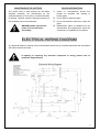
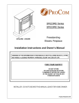
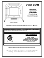
PRO-COM
V50HYLC
V50HYLD
Freestanding
Electric Fireplace
V50HYLC SHOWN
Installation Instructions and Homeowner’s Manual
WARNING! IF THE INFORMATION IN THIS MANUAL IS NOT FOLLOWED EXACTLY, A FIRE MAY RESULT
CAUSING PROPERTY DAMAGE, PERSONAL INJURY OR LOSS OF LIFE.
FOR YOUR SAFETY
DO NOT STORE
OR USE GASOLINE OR OTHER
FLAMMABLE VAPORS OR LIQUIDS
IN THE VICINITY OF THIS OR ANY
OTHER APPLIANCE
ANSI/UL1278. MOVABLE AND WALL-OR CEILING HUNG ELECTRIC ROOM HEATERS
INSTALLER: DO NOT DISCARD THIS MANUAL-LEAVE FOR HOME OWNER
CUSTOMER: PLEASE RETAIN THIS MANUAL FOR FUTURE USE
TABLE OF CONTENTS
PLEASE READ THE INSTALLATION & OPERATION INSTRUCTIONS BEFORE
USING THIS APPLIANCE
WE ARE PLEASED THAT YOU HAVE CHOSEN TO PURCHASE AN ELECTRIC FIREPLACE MANUFACTURED BY
NANJING PRO-COM ELECTRIC APPLIANCE CO., LTD
IMPORTANT: Read all instructions and warnings carefully before starting installation. Failure to
follow these instructions may result in a possible electric shock, fire hazard and will void the
warranty.
Important instructions ……………………………………………………………………2
General…………………………………………………………………………………..2
Locating Your Electric Fireplace………………………………………………………2
Clearance To Combustibles…………………………………………………………...3
Electrical Connections…..………………………………………………… ………….3
Electrical Specifications………………………………………………………………..3
Service Instructions…………………………………………………………………………..3
Replacing Light Bulbs…………………………………………………………………..3
Glass Information……………………………………………………………………….4
Maintenance of Motors…………………………………………………………………4
Electrical Wiring Diagram………………………………………………………………4
Operating Instructions……………………………………………………………………….5
On/Off Switch…………………………………………………………………………...5
Heater Control…………………………………………………………………………..5
Instructions for power…………………………………………………………………..5、6
Specifications………………………………………………………………………..….6
Replacement Parts List (V50HYLC) ………………………………………………………7
Replacement Parts Pictures…………………………………………………………...7、8
Replacement Parts List (V50HYLD)…………………………………………………………9
Replacement Parts Pictures……………………………….………………………....9、10
1
IMPORTANT INSTRUCTIONS
GENERAL
1.
2.
Read all instructions before using this appliance.
This appliance is hot when in use. To avoid burns, do
electrically grounded in accordance with local
not let bare skin touch hot surfaces. Keep
codes with the current CSA C22.1 Canadian local
combustible materials, such as furniture, pillows,
codes of for USA installations. Follow local codes
bedding, papers, clothes, and curtains at least 3
and
feet(1m.) from the front of this appliance.
3. CAUTION: Extreme caution is
necessary when any heater is used
by or near children or invalids and
whenever the heater is left Operating
and unattended.
4. Always unplug heater when not in
use.
5. Do not operate any heater with a
damaged cord or plug or after the
heater malfunctions, has been
dropped or damaged in any manner.
6. Any repairs to this appliance should be carried out by
a qualified service person.
7.
8.
9.
13. When this appliance is installed, it must be
ANSI/NFPA
NO.70 and Canadian Code: CZ 22.2 NO.0.
National
Electrical
Code,
14. Do not insert or allow foreign objects to enter any
ventilation or exhaust opening as this may cause
electric shock, fire or damage to the appliance.
15. To prevent fire, do not block air intakes or exhaust
in any manner. Do not use on soft surfaces, such
as a bed, where openings may become blocked.
16. Caution this appliance gets hot and it contains
internal parts that could arc or spark. Do not use it
in areas where gasoline, paint, or flammable
liquids are used or stored. This electric fireplace
should not be used as a drying rack for clothing.
Also, do not have Christmas stockings or
decorations hung on or near it.
Under no circumstances should this electric fireplace
17. Use this appliance only as described in this
be modified. Parts having to be removed for
manual. All other uses not recommended by the
servicing must be replaced prior to operating this
manufacturer may cause fire, electric shock, or
electric fireplace again.
injury.
Do not use outdoors.
18. Avoid the use of an extension cord because it may
This heater is not intended for use in bathrooms,
overheat and cause a fire hazard. However if you
laundry areas or similar indoor locations. Never use
must use an extension cord, the cord shall be
this appliance near a bathtub or vicinity of water.
NO.16, 1900 Watts. The extension cord must be a
10. Do not run cord under carpeting. Do not cover cord
three wire cord with grounding type plug and cord
with throw rugs, runners or the like. Arrange cord
away from traffic areas and where it will not be
connector.
19. SAVE THESE INSTRUCTIONS.
tripped over.
11. To disconnect this appliance, turn controls to the off
position and remove plug from outlet.
12. Connect to properly grounded outlets only.
LOCATING YOUR ELECTRIC
FIREPLACE
Your new freestanding electric fireplace may be
installed virtually anywhere in your home.
However when choosing a location for your
new electric fireplace, ensure that the general
instructions are followed. For best effect results, install
the electric fireplace out of direct sunlight.
2
CLEARANCE TO COMBUSTIBLES
WARNING: Electrical outlet wiring
must comply with local building
codes and all other applicable
regulations to reduce the risk of
fire, electrical shock and injury.
Back………………2”/50.8mm
Sides……………..6”/156.4mm
Floor……………..0”/0mm
Top……………….24”/610mm
WARNING: Do not use this
fireplace if any part of it has been
under water. Immediately call a
qualified service technician to
inspect the fireplace and replace
any part of the electrical system if
necessary.
ELECTRICAL CONNECTION
A 15 AMP, 120 Volt, 60Hz circuit with a properly grounded
outlet is required. Preferably, the heater will be on a
dedicated circuit. Other appliances on the same circuit
may cause the circuit breaker to trip or the fuse to blow
ELECTRICAL SPECIFICATIONS
when the heater is on operation. The unit comes standard
with a 6’ (1828mm) long three wire cord exiting from the
Voltage………………120 VAC/60Hz
Total Amps…………..11.3 Amps
Total Watts…………..1345 Watts
Heater Ratings………1200 Watts
rear of the fireplace. Plan the installation to avoid the use
of an extension cord. If an extended cord must be used, it
must be a minimum 16 AWG three wire with grounding
type plug connector and rated no less than 1900 Watts.
SERVICE INSTRUCTIONS
WARNING: Disconnect power
before
attempting
any
maintenance or cleaning to
reduce the risk of fire, electrical
shock or personal injury
5.
take them out.
6.
Examine the bulbs to determine which one
needs to be replaced.
7.
REPLACING LIGHT BULBS
Remove the two screws of the front baffle and
While holding the socket, unscrew the defective
bulb(s).
This fireplace uses two clear 120 Volt, 60 Watt, E-12
8.
socket base light bulbs (small base, chandelier candle
and screwing them in.
type).The 60 Watt bulbs are located under the log
9.
set/ember bed. For convenience, if one of the bulbs
Install the new light bulb(s) by holding the socket
Reinstall the baffle、log set and screen. Follow
the above procedure in reverse order.
burns out, it may be a good idea to replace both of the
light bulbs.
1.
Turn off power to the unit by unplugging the power
cord.
2.
Let fireplace cool if it has been operating.
3.
Open the front door by pulling the handle.
4.
Remove the two screws that secure the log set in
WARNING: Do not exceed 60
Watts per bulb. Use of higher
rated bulbs may result in a fire
causing property damage and
personal injury.
position.
3
MAINTENANCE OF MOTORS
The motors used on both blowers fan and flame
simulator assembly are prelubricated for the
extended warranty of the motor, no further lubrication
is required. However, periodic cleaning/vacuuming of
the fan/heater unit is recommended.
GLASS INFORMATION
1. Under no circumstances should this
product be operated with missing or
broken glass.
2. Do not strike or slam the glass.
3. Do not use abrasive cleaners to clean the
glass.
WARNING: Make sure that the
power is turned off before
proceeding.
4. Replacement glass is available from the
manufacturer and replacement should be
carried out by a qualified service person.
ELECTRICAL WIRING DIAGRAM
Any electrical repairs or rewiring of this unit should be carried out by a licensed electrician and accordance
with national and local codes.
If repairing or replacing any electrical component or wiring, please refer to
schematic diagram below.
4
Operating Instructions
This section provides easy step by step instructions for operating your fireplace.
1. Make sure the unit is unplugged from the power source (see warning on page 6)
2. Plug the heater into a 15AMP/120volt outlet. If the cord does not reach, you may use an extension
cord rated for a minimum of 1900 watts.
To access the controls, open the door of the fireplace at the front of the unit (see Figure A).
Figure A
A.
PROPER WAY TO INSTALLING HANDLE
Insert handle’s threading tip
into the hole, turn slightly the
handle to proper position and
make threading tip get through
the hole, screwing the nut
supplied. See Figure B
Figure B
B. MAIN ON/OFF SWITCH
The on/off switch supplies power to all fireplace functions (heater/flame).
C. HEATER ON/OFF SWITCH 1
The HEATER ON/OFF SWITCH 1 supplies power to the heater fan and the heater element.
NOTE: When switched ON, the heater fan and the heater element will operate. But it gives an
output of 600W. It is just half of the total power.
D. HEATER ON/OFF SWITCH 2
The HEATER ON/OFF SWITCH 2 supplies power to the heater element, and the remaining
voltage to the heater.
NOTE: When switched ON, the heater fan and the heater element will still operate. But it gives
an another output of 600W. Then, the heater will arrive its total value of 1200W. The heater fan
and the heater element will not operate if SWITCH 2 is ON but SWITCH 1 is OFF.
5
E. INSTRUCTIONS FOR POWER
This heater is for use on 120 volts only. The cord has a plug as shown at A in the following figure.
An adapter as shown at C is available for connecting three-blade grounding-type plugs to
two-slot receptacles. The green grounding lug extending from the adapter must be connected to
a permanent ground such as a properly grounded outlet box. The adapter should not be used if
a three-slot grounded receptacle is available.
Warning: Before servicing this heater be sure to unplug heater from wall outlet. Do not only turn off heater
from the main “ON/OFF” switch, be sure to unplug this heater.
5
(Adaptor NOT permitted in Canada)
Under CZ22.2 NO. 0 standard
SPECIFICATIONS:
Model: V50HYLD
Model:V50HYLC
Voltage:
120V/60HZ
Total Watts: 1345W
Total Amps:
11.3A
Voltage:
Heating Ratings: 1200W
120V/60HZ
Total Amps:
Total Watts: 1345W
Heating Ratings: 1200W
Dimensions, Inches (H x W X D)
Dimensions, Inches (H x W X D)
Fireplace
24-3/4”x23-3/8”x13-3/8”
Fireplace
24-7/8”x23-7/8”x13-7/8”
Carton
27-1/2”x29-3/8”x15-3/8”
Carton
27-1/2”x29-3/8”x15-3/8”
11.3A
Weight, Pounds
Weight, Pounds
Fireplace
35
Fireplace
35
Shipping
45
Shipping
45
6
Replacement Parts List
V50HYLC
Item #
Part Description
1
2
3
4
5
6
7
8
9
10
11
12
13
14
15
16
17
18
19
20
21
VC Top Panel Right Part
Fan/Heater Assembly
Synchronization Motor-120Volt AC w/Terminal
Cord Power 16/3 HPN w/Terminals
ON/OFF Switch
VC Top Panel Left Part
VC Top Panel (Middle Part)
Flame Generator Assembly
Light Bulb Socket
Right Side-panel
Left Side-panel
Door
Door Pivot
Door Adorning
Leg(s)
Back Panel
Electrothermal Hood
Door Knob
Knob Dressing
Air Transfer Panel
Glistening Paper
Part Number
VL107-02Q
NFHTX186/V
VL051-01
NFHL008-A
VL067-01
VL107-02Q
VL107-02P
VB17001-C-3
VL054-01
VL102-01
VL101-01
VL108-01
VL111-01P
VL117-01-A
SL017-04A
VL109-01
VL035
VCL008
VCL008-01
VCL011
VB17001-C-4
7
REPLACEMENT PARTS PICTURES OF V50HYLC
9
5
2
4
3
8
OR
22
8
Replacement Parts List
V50HYLD
Item #
Part Description
1
2
3
4
5
6
7
8
9
10
11
12
13
14
15
16
17
18
19
20
Top Panel
Fan/Heater Assembly
Synchronization Motor-120Volt AC w/Terminal
Cord Power 16/3 HPN w/Terminals
ON/OFF Switch
Left Side Panel
Right Side Panel
Flame Generator Assembly
Light Bulb Socket w/Wiring Assembly
Door
Door Pivot
Door Knob
Knob Dressing
Legs
Electrothermal Hood
Back Panel
Door Adorning
Cross Band
Air Transfer Panel
Glistening Paper
Part Number
VL107-02F
NFHTX186/VB17-000G
VL051-01
NFHL008-A
VL067-01
VL101-01P
VL101-02P
VB17001-C-3
VL054-01
VL108-01
VL111-01P
VCL008
VCL008-01
VCL019-01
VL035
VL109-03
VL117-01-A
VL113-01G
VCL011
VB17001-C-4
9
REPLACEMENT PARTS PICTURES OF V50HYLD
5
3
2
9
4
8
OR
21
7
10