1
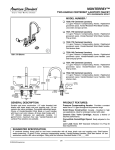
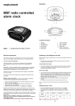
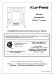
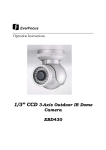
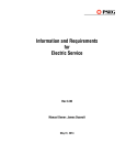
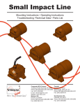
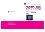
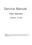
Troubleshooting Guide
NO RASTER
Check +B voltage at J405
Normal
Is the voltage at pin8,37
of IC501 8V?
Yes
No
Check/Replace
IC501
No
Check/Replace
Q451, T451, R452
No
Check/Replace
Q452
Does the square
waveform from pin40 of
IC501 appear?
Yes
Is the waveform of
collector of Q451 normal?
0V
No
Check the voltage 5V,
12V lines
OK
Check I2C BUS lines
(SDA, SCL)
Check
Fuse of AC line
OK
Check the voltage of
C808, C809
254~380V
Check the voltage
of pin9 of IC801
Yes
Check/Replace
T701
Check/Replace
Fuse, D801, IC801
0V
Check/Replace
D801
Lower than 6V
Check/Replace
D802, D805, D807,
Q801, IC801
Yes
Is the waveform of
collector of Q452 normal?
Open
Check/Replace
IC803, D835, D829
Check the 12V, 5V lines are
shorted.
NO SOUND
(PICTURE OK)
NO
Check/Replace
IC101
(No AM Sound)
(No NICAM or FM Sound)
Check the Audio signal of
pin12 of IC101 normal
Check whether Sound
system of MENU OSD
is correct or not
Yes
Correct
Check the Audio signal of
pin55 of IC601 normal
Yes
Is the SIF signal of
pin20 of IC101 normal?
No
Yes
Check/Replace
Q605, AM line
Are the Audio signal of
pin28, 29 of IC601 normal?
Yes
Are the Audio signal of
pin2, 5 of IC651 normal?
Yes
Are the Audio signal of
pin7,11 of IC651 normal?
Yes
Check/Replace
C660, C664, Speaker
Incorrect
Set correct Sound
system
No
Check/Replace
IC101
No
Check/Replace
X601, IC601, IC602
No
Check Ro, Lo lines
No
Check the voltage
of pin10 of IC651
NO PICTURE/NO SOUND
(RASTER OK)
Does the Auto programme
operation?
Yes
No
Check/Replace
IC101
Is the CVBS signal of pin10
fo IC101 normal?
Yes
Go to NO PICTURE Block,
NO SOUND Block
No
Check the voltage
5V, 12V, 33V of Tuner
OK
Check I2C BUS
lines (SDA, SCL)
OK
Check/Replace
Tuner
NG
Check/Replace
ZD182, 5V, 12V, 33V
power lines
NO RASTER
(SOUND OK)
Check the voltage of
CPT Heater
Normal
Abnormal
Check/Replace
T701
Check the voltage of HV,
SCREEN of CPT
Normal
Check/Replace
CPT Board
Abnormal
Check the Heater pulse of
pin 9 of T701
Normal
Check/Replace
Connector, FR705, FR901
Abnormal
Check/Replace
T701
NO PICTURE/NO COLOR
Is the CVBS signal of pin10 of
IC101 normal?
Yes
Is the CVBS signal of pin16 of
IC201 normal?
Yes
Is the CVBS signal of pin 3 of
IC150 normal?
Yes
Is the CVBS signal of pin 2 of
IC150 normal?
Yes
Is the CVBS signal of pin13 of
IC501 normal?
Yes
Is the Y signal of pin 27 of
IC501 normal?
Yes
Are R-Y, B-Y signal of
pin 31,32 of IC501 normal?
Yes
Are R,G,B signal of
pin19, 20, 21 of IC501 normal?
Yes
Check CPT Board
No
Check/Replace
IC101
No
Check/Replace
IC201
No
Check/Replace
Q151
No
Check/Replace
IC150
No
Check/Replace
Q150
No
Check/Replace
IC502
No
Check/Replace
IC502
No
Check/Replace
IC501
NO TELETEXT
Check the voltage
5V of C845
Abnormal
Check the 5V line
to be correct
Normal
Abnormal
Check/Replace
L154
No
No
Check/Replace
IC201
Check whether video signal is
at the pin16 of IC201 or not
Yes
Check the CVBS line
Abnormal
Check the voltage of C176
4.8~5.2V
Check whether video signal is
at pin3 of IC150 or not
Yes
Check I2C BUS lines
(SDA, SCL)
OK
Check pin19, 20, 22, 23
of IC150
Check/Replace
IC150, IC151
Check/Replace
IC501
ADJUSTMENT INSTRUCTIONS
* Safety Precautions
1. It is safe to adjust after using insulating transformer
between the power supply line and chassis input to
prevent the risk of electric shock and protect the
instrument.
2. Never disconnect leads while the TV receiver is on.
3. Don't short any portion of circuits while power is on.
4. The adjustment must be done by the correct
appliances. But this is changeable in view of
productivity.
5. Unless otherwise noted, set the line voltage to 230Vac
+_10%, 50Hz.
Modulation
Output level
38.9MHz
OFF
10mVp-p
(Table 1)
* SECAM L' Adjustment
NOTE : This adjustment should be performed after PIF
adjustment.
Test Point : TP1
* Test Equipment required
1.
2.
3.
4.
5.
Frequency
Adjust
RF signal generator (with pattern generator)
DC Power Supply
Multimeter (volt meter)
Oscilloscope
Color analyzer
: VR101
1) Tune the TV set to receive a SECAM-L' signal.
2) Adjust VR101 so that the DC voltage may be indicated
2.6+_0.1Vdc.
Main Board(Component side view)
* SECAM L/L' sound Adjustment
MULTIMETER
MAIN BOARD
TDA9811
VR101
17
TP1
23
VL102
4.5M
TP2
5
CERAMIC CAP.
10000pF
4
1
55 AM INPUT
VR102
J116
61
GND
Z102
CERAMIC CAP.
10000pF
TUNER
IC601
MSP3410
C638
AGC
ADJ.
RF SIGNAL
GENERATOR
: VL102
OSCILLOSCOPE
IC101
38.9MHz
10mVp-p
5 0.1Vdc
DC POWER
SUPPLY
Adjust
L'
ADJ.
16
9
TP3
30
VL101
PIF
32
Test Point : C638(Refer to the Fig.2)
(TP point is on the
copper side of PCB)
Fig. 2
TP1 : pin23 of IC101
TP2 : pin9 of IC101
TP3 : pin30 of IC101
TP5 : J156
TP5
J156
A GC
TP
Noise
Level
Fig. 1 : Connection Diagram of Equipment for PIF Adjustment
(Before Adjustment)
(After Adjustment)
* PIF (Picture Intermediate Frequency) Adjustment
Test Point : TP1
Adjust
: VL101
1) Connect the measuring equipment to the Main Board as
shown in Fig.1.
2) Set RF frequency and output level of RF SIGNAL
GENERATOR as shown Table 1.
3) Turn on DC power supply.
4) Adjust VL101 so that the DC voltage may be indicated
2.6+_0.1Vdc.
1) Connect the Oscilloscope to the Main Board as shown
in Fig. 2.
2) Set pattern generator as shown Table 2.
3) Adjust VL102 so that the Noise level is minimized.
System
SECAM-L
Signal Pattern Sound signal Carrier signal
Color bar
(Table 2)
Off
On
* Vertical/Horizontal/E-W (East-West)
Adjustment (LINE SVC 1)
NOTE : These adjustments are already aligned at
the time of manufacture for optimum
performance. Readjustment of them
should not be necessary unless IC02
(EEPROM) is defective. Because all the
information of these adjustment are
memorized in that IC.
Adjustment Procedures
1) Tune the TV set to receive a digital circle pattern unless
otherwise noted.
2) Press OK button on Control Board continuously and OK
button on remote controller then you can find On
Screen Display. (Refer to the following Fig.3).
3) Press PR+ or PR- button for desirous function
adjustment.
4) Press VOL+ or VOL- button for correct picture.
5) Press OK button to memorize all the adjusted data.
6) After finishing adjustment, press TV/AV button on
remote controller then TV is changed from SVC mode
to normal mode.
[LINE SVC1]
VL
VA
SC
VS
HS
1
CH5
43
21
35
35
31
EW
EP
EC
ET
50HZ*
37
39
29
20
EW--(Horizontal Width)
Adjust to that a digital circle pattern looks like exact circle.
EP--(East-west Parabola)
Adjust so that middle portion of the outermost left and right
vertical line looks like parallel with vertical lines of the CPT.
EC--(East-west Corner)
Adjust so that the vertical line at every 4 corners of the
screen looks like parallel with the vertical lines of the CPT.
ET--(East-west Trapezium)
Adjust to make the length of top horizontal line same with it
of the bottom horizontal line.
* White Balance Adjustment.(LINE SVC 2)
NOTE : This adjustment should be performed after screen
voltage adjustment.
1) Tune the TV set to receive an 100% white pattern.
2) Press Number 2 button on remote controller in the SVC
Mode (press OK button on control board continuously
and OK button on remote controller) then you can find
On Screen Display. (Refer to the following Fig.4).
3) Press PSM (RED) button on remote controller. (Standard
picture)
4) Press PR+ or PR- button for desirous function
adjustment.
5) Adjust VOL+ or VOL- button for GG31.
6) Adjust VOL+ or VOL-button in each status of "RG--"/"BG--"
for X=288+_8, Y=295+_8 with color analyzer (color
temperature 9000oK).
[LINE SVC2]
*: This is only displayed according to
receiving system.
PAL/SECAM System
: 50Hz
[ NTSC System
: 60Hz
1
CH5
RG31
GG31
BG23
DY12*
Fig. 3
VL--(Vertical Linearity)
Adjust so that the boundary line between upper and lower
half is in accord with geometric horizontal center of the CPT.
VA--(Vertical Amplitude)
Adjust so that the circle of a digital circle pattern may be
located within the effective screen of the CPT.
SC--(Vertical "S" correction)
Adjust so that all distance between each horizontal lines are
to be the same.
VS--(Vertical Shift)
Adjust so that the horizontal center line of a digital circle
pattern is in accord with geometric horizontal center of the
CPT.
HS--(Horizontal Shift)
Adjust so that the vertical center line of a digital circle pattern
is in accord with geometric vertical center of the CPT
Fig. 4
* : Never change this data, this is an important
reference data for TV.
Ref) PAL I/I': DY15
NOTE : If press Number 3 button on the remote controller
in the SVC mode then you can find On Screen
Display. (Refer to the following Fig.5).
[LINE SVC3]
FP
NP
SP
SV
1
CH5
30
110
23
75
Fig. 5
* Never change these data, these are important
reference data for TV
* RF AGC (Automatic Gain Control) Adjustment
* Focus Adjustment
NOTE: This adjustment should be performed after
warming up for 10 minutes.
Test Point : TP5 (J156) or Observing Display
Adjust
: VR102
Test Point : Observing Display
The RF AGC control (VR102) was aligned at the time of
manufacture for optimum performance over a wide range
conditions. Readjustment of VR102 should not be
necessary unless unusual local conditions exist, such as ;
Adjust
1) Tune the TV set to receive an inactive channel station.
2) Adjust the Focus control of FBT for best overall focus.
1) Channel interference in a CATV system.
2) Picture bending and/or color beats, which are unusually
due to excessive RF signal input when the receiver is
too close to a transmitting tower or when the receiver
is connected to an antenna distribution system where
the RF signal has been amplified. In this case, the input
signal should be attenuated (with pad or filter) to a
satisfactory level.
3) Picture noise caused by "broadcast noise" or weak
signal.
If the broadcast is "clean" and the RF signal is at least
1mV (60dBu), the picture will be noise free in any area.
Adjusting the VR102(RF AGC) control to one end of
rotation will usually cause a relatively poor signal to noise
ratio;
Adjusting to the other end of rotation will usually cause a
degradation of over load capabilities resulting in color
beats or adjacent channel interference. For best results,
adjust the VR102 control while performing on all over local
channels, or the voltage at J156 will be 6.4¡ 0.1Vdc in RF
level 60+_1dBuV.
* Screen Voltage Adjustment
Test Point : RK (Red Cathode of CPT Board)
Adjust
: Screen Control of FBT
1) Tune the TV set to receive a digital pattern.
2) Press PSM (RED) button on remote controller. (standard
picture)
3) Connect the probe of oscilloscope to the RK (Red
Cathode) of CPT Board.
4) Adjust Screen Volume of FBT so that the waveform is
the same as below Fig. 6.
Horizontal
FlyBack Time
Black level
170Vp-p
White level
GND for dc
Fig. 6: The waveform of RK(Red Cathode) of CPT Board
: Focus control of FBT
PURITY & CONVERGENCE ADJUSTMENT
Caution:
Convergence and Purity have been factory aligned. Do not
attempt to tamper with these alignments.
However, the effects of adjacent receiver components, or
replacement of picture tube or deflection yoke may require the
need to readjust purity any convergence.
5. Reconnect the internal degaussing coil.
6. Position the beam bender locking rings at the 9 o'clock
position and the other three pairs of tabs (2,4 and 6 pole
magnets) at the 12 o'clock position.
DEFLECTION YOKE
PURITY &CONVERGENCE
MAGNET ASSEMBLY
6-POLE
6-POLE
MAGNETS
MAGNES
PURITY MAGNET(2-POLE)
6-POLE
,
,,,,,,,,,,
,,,,,,
,,,,,,,,,,
,
,,,,,,,,,
,,,,,,
RUBBER
WEDGES
,,,,,,,,,,,,,
,
,,,,,,,,
,,,,,,,
,,,,
4-POLE
X-AXIS YOKE MAGNET
POSITIONING
(L/R PURITY)
PURITY MAGNET
4-POLE
GLASS CLOTH TAPE
CONVERGENCE
MAGNETASSEMBLY
ASSEMBLY
CONVERGENCE MAGNET
* Purity Adjustment
This procedure DOES NOT apply to bonded yoke and picture
tube assemblies.
The instrument should be at room temperature (60 degrees F or
above) for six (6) hours and be operating at low beam current
(dark background) for approximately 20 to 30 minutes before
performing purity adjustments.
CAUTION: Do not remove any trim magnets that may be
attached to the bell of the picture tube.
1. Remove the AC power and disconnect the internal
degaussing coil.
2. Remove the yoke from the neck of the picture tube.
3. If the yoke has the tape version beam bender, remove it and
replace it with a adjustable type beam bender (follow the
instructions provided with the new beam bender)
4. Replace the yoke on the picture tube neck, temporarily
remove the three (3) rubber wedges from the bell of the
picture tube and then slide the yoke completely forward.
3-2
7. Perform the following steps, in the order given, to prepare the
receiver for the purity adjustment procedure.
a. Face the receiver in the "magnetic north" direction.
b. Externally degauss the receiver screen with the television
power turned off.
c. Turn the television on for approximately 10 seconds to
perform internal degaussing and then turn the TV off.
d. Unplug the internal degaussing coil. This allows the
thermistor to cool down while you are performing the purity
adjustment. DO NOT MOVE THE RECEIVER FROM ITS
"MAGNETIC NORTH" POSITION.
e. Turn the receiver on and obtain a red raster by increasing
the red bias control (CW) and decreasing the bias controls
for the remaining two colors (CCW).
f. Attach two round magnets on the picture tube screen at 3
o'clock and 9 o'clock positions, approximately one (1) inch
from the edge of the mask (use double-sided tape).
1.ADJUST YOKE Z-AXIS FIRST
TO GET EQUAL BLUE
COLOR CIRCLES
2 .ADJUST BEAM BENDER 2 POLE
MAGNET TO GET FOUR EQUAL
COLOR CIRCLES
MAGNETS
RED
RED
8. Referring to above, perform the following two steps:
a. Adjust the yoke Z-axis to obtain equal blue circles.
b. Adjust the appropriate beam bender tabs to obtain correct
purity (four equal circles).
6. Reconnect the internal degaussing coil and apply AC power.
9. After correct purity is set, tighten the yoke clamp screw and
remove the two screen magnets.
8. Unplug the internal degaussing-coil.
10. Remove the AC power and rotate the receiver 180 degrees
(facing "magnetic south").
11. Reconnect the internal degaussing coil.
12. Turn the receiver on for 10 seconds (make sure the receiver
came on) to perform internal degaussing, and then turn the
receiver off.
7. Turn the receiver on for 10 seconds to perform internal
degaussing and then turn the receiver off again.
9. Turn on the receiver, connect a signal generator to the VHF
antenna terminal and apply a crosshatch signal.
Caution: During the convergence adjustment procedure, be
very careful not to disturb the purity adjustment tabs
are accidentally move, purity should be confirmed
before proceeding with the convergence adjustments.
Note: Make sure the focus is set correctly on this instrument
before proceeding with the following adjustment.
13. Unplug the internal degaussing coil.
14. Turn on the receiver and check the purity by holding one (1)
round magnet at the 3 o'clock and a second round magnet at
9 o'clock position. If purity is not satisfactory, repeat steps 8
through 14.
15. Turn off the receiver and reconnect the internal degaussing
coil.
10. Converge the red and blue vertical lines to the green vertical
line at the center of the screen by performing the following
steps (below TABLE).
a. Carefully rotate both tabs of the 4-pole ring magnet
simultaneously in opposite directions from the 12 o'clock
position to converge the red and blue vertical lines.
b. Carefully rotate both tabs of the 6-pole ring magnet
simultaneously in opposite directions form the 12 o'clock
position to converge the red and blue (now purple)
vertical lines with the green vertical line.
* Convergence Adjustment
Caution: This procedure DOES NOT apply to bonded yoke and
picture tube assemblies.
Do not use screen magnets during this adjustment
procedure. Use of screen magnets will cause an
incorrect display.
1. Remove AC power and disconnect the internal degaussing
coil.
2. Apply AC Power and set the brightness to the Picture Reset
condition. Set the Color control to minimum.
3. Apply 8V to the pin.
11. Converge the red and blue horizontal with the green line at
the center of the screen by performing the following steps.
(below TABLE)
a. Carefully rotate both tabs of the 4-pole ring magnet
simultaneously in the same direction (keep the spacing
between the two tabs the same) to converge the red and
blue horizontal lines.
b. Carefully rotate both tabs of the 6-pole ring magnet
simultaneously in same direction (keep the spacing
between the two tabs the same) to converge the red and
blue (now purple) horizontal lines with the green
horizontal line.
c. Secure the tabs previsouly adjusted by locking them in
place with the locking tabs on the beam bender.
4. Adjust the Red, Green and Blue Bias controls to get a dim
white line.
5. Remove the AC power and 8V from the pin.
3-3
ROTATION DIRECTION
OF BOTH TABS
RING
PAIRS
MOVEMENT OF RED
AND BLUE BEAMS
B
B
OR
OPPOSITE
R
4
POLE
SAME
B
R
R
OR
B
B
R
B
OR
OPPOSITE
R
R
6
POLE
SAME
UP/DOWN ROCKING OF THE YOKE
UP/DOWN
ROCKINGROTATION
OF THE YOKE
CAUSES
OPPOSITE
OF RED
CAUSES
AND
BLUEOPPOSITE
RASTERS ROTATION OF RED
B
R
OR
B
R
LEFT/RIGHT ROCKING OF THE YOKE
LEET/RIGHT
ROCKING
OF THE YOKE
CAUSES
OPPOSITE
SIZE CHANGE
OF THE
CAUSES
OPPOSITE
SIZE CHANGE OF
RED
AND BLUE
RASTERS
AND BLUE RASTERS
THE RED AND BLUE RASTERS
GREEN
GREEN
ADJUSTMENT
VIEWING
AREA
GREEN
BLUE
ADJUSTMENT
VIEWING
AREA
RED
RED
BLUE
BLUE
RED
RED
RED
RED
GREEN
BLUE
TV
SCREEN
GREEN
12. While watching the 6 o'clock positions on the screen, rock the
front of the yoke in a vertical (up/down) direction to converge
the red and blue vertical lines. (Fig upper left)
13. Temporarily place a rubber wedge at the 12 o'clock position
to hold the vertical position or the yoke.
14. Check the 3 o'clock and 9 o'clock areas to confirm that the red
and blue horizontal lines are converged.
If the lines are not converged, slightly offset the vertical tilt of the
yoke (move the rubber wedge if necessary) to equally balance the
convergence error of the horizontal lines at 3 o'clock and 9 o'clock
and the vertical lines at 6 o'clock and 12 o'clock.
15. Place a 1.5 inch piece of glass tape over the rubber foot at
the rear of the 12 o'clock wedge.
16. While watching the 6 o'clock and 12 o'clock areas of the
screen, rock the front of the yoke in the horizontal (left to
right) motion to converge the red and blue horizontal lines.
(Fig. upper right)
3-4
17. Temporarily place a rubber wedge at the 5 o'clock and 7
o'clock positions to hold the horizontal position of the yoke.
18. Check the 3 o'clock and 9 o'clock areas to confirm that the
red and blue vertical lines are converged. If the lines are not
converged, slightly offset the horizontal tilt of the yoke (move
the temporary rubber wedges if necessary) to equally
balance the convergence error of the horizontal lines at 6
o'clock and 12 o'clock and the vertical lines at 3 o'clock and 9
o'clock.
19. Using a round magnet confirm purity at the center, right and
left sides and corners. See Purity Adjustment Procedure.
20. Reconfirm convergence and apply a 1.5 inch piece of glass
tape over the rubber foot at the rear of the 5 o'clock and the 7
o'clock wedges.
SDA
44
SIF
47
VIF
27
28
30
31
TDA4474M
VIF-S/W
STD-S/W
SIF-S/W
VCO
L107
38.9M
SCL
7
7
8
8
9
IIS-CL
9
10
IIS-WS
Head-Phone
Jack
10
22
21
L
R
25
DPL3519A 24
DOLBY
PRO-LOGIC 22
21
PH1601
DOLBY JACK
L
R
C
S
ADJUSTMENT
SOUND
EXT.SOUND
P/N: 484-933A-S1(1/2)
971120
WAVEFORM
VERTICAL
HORIZONTAL
VIF/CVBS
EXT.VIDEO
WAVEFORM
SOUND
VERTICAL
HORIZONTAL
P/N: 484-933A-S1(2/2)
971120