1
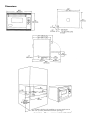
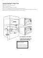
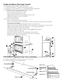
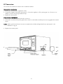
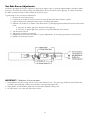
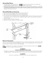
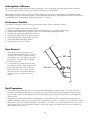
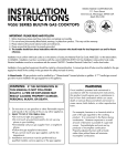
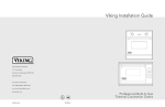
INSTALLATION
INSTRUCTIONS
VIKING RANGE CORPORATION
111 Front Street
Greenwood, Mississippi 38930 USA
(662)453-1200
VGSO166 BUILT-IN GAS OVEN
Retain for Future Use
IMPORTANT - PLEASE READ AND FOLLOW
•Before beginning, please read these instructions completely and carefully.
•Do not remove permanently affixed labels, warnings, or plates from the product. This may void the warranty.
•Please observe all local and national codes and ordinances.
•Please ensure that this product is properly grounded.
•The installer should leave these instructions with the consumer who should retain for local inspector’s use and for
future reference.
Installation must conform with local codes or in the absence of codes, the National Fuel Gas Code ANSI Z223.1-latest
edition. IN CANADA: Installation must be in accordance with the current CAN/CGA B149.1 & 2 Gas Installation codes
and/or local codes. Electrical installation must be in accordance with the current CSA C22.1 Canadian Electrical Codes
Part 1 and/or local codes.
In Massachusetts: All gas products must be installed by a “Massachusetts” licensed plumber or gasfitter. A “T” handle
type manual valve must be installed in the gas supply line to the appliance.
WARNING: IF THE INFORMATION IN
WARNING
THIS MANUAL IS NOT FOLLOWED
EXACTLY, A FIRE OR EXPLOSION MAY
RESULT CAUSING PROPERTY DAMAGE,
PERSONAL INJURY, OR DEATH.
If not installed, operated and maintained in
accordance with the manufacturer’s instructions, this
product could expose you to substances in fuel or
from fuel combustion which can cause death or
serious illness and which are known to cause cancer,
birth defects, or other reproductive harm.
1. Do not store or use gasoline or other flammable vapors
and liquids in the vicinity of this or any other appliance.
2. WHAT TO DO IF YOU SMELL GAS:
•Do not try to light any appliance.
•Do not touch any electrical switch; do not use any
phone in your building.
•Immediately call your gas supplier from a neighbor’s
phone.
•Follow the gas supplier’s instructions.
•If you cannot reach your gas supplier, call the fire
department.
3. Installation and service must be performed by a
qualified installer, service agency, or the gas supplier.
For example, benzene is a chemical which is part
of the gas supplied to the cooking product. It is
consumed in the flame during combustion.
However exposure to a small amount of benzene
is possible if a gas leak occurs. Formaldehyde
and soot are by-products of incomplete
combustion. Properly adjusted burners with a
bluish rather than yellow flame will minimize
incomplete combustion.
Specifications
Description
Cutout width
Cutout height
Cutout depth
33 7/8” (86.0 cm)
22 5/8” (57.5 cm)
Minimum 24” (61.0 cm); unit extends into cutout 23 7/8” (60.6 cm); cord protrudes 1/2” (1.3 cm) beyond
23” (58.4 cm)
Cutout height from floor Minimum 17” (43.2 cm)
Overall width
35 1/4” (89.5 cm)
Overall height
23” (58.4 cm)
Overall depth
To edge of side25 1/4” (64.1 cm)
To end of handle bracket - 27 3/8” (69.5 cm)
With door open 39 1/2” (100.3 cm)
Gas requirements
Shipped natural gas standard; field convert to LP/Propane with standard convertible regulator; accepts
standard 1/2” (1.3 cm) ID gas service line
Electrical requirements
120 VAC/60 Hz
4 ft. (121.9 cm)m 3-wire cord with grounded 3-prong plug attached to product.
Maximum amp usage
8.0 amps
Infrared broil burner rating 18,000 BTU Nat./15,000 BTU LP
(5.3 kW Nat./4.4 kW LP)
Bake burner rating
Two 15,000 BTU ea. Nat./LP
(Two 4.4 kW ea. Nat./LP)
Oven interior Dimensions Width - 24 1/8” (61.3 cm)
Height - 13 3/4” (34.9 cm)
Depth- 17 1/8” (43.5 cm)
Overall- 3.3 cu. ft. (94 liter)
•Convection Bake/Broil Oven
•Three Racks
Approximate shipping wt. 257 lb. (115.7 kg)
General Information
1. WARNING: The use of cabinets for storage above the appliance may result in a potential burn hazard.
Combustible items may ignite, metallic items may become hot and cause burns. If a cabinet storage is to be
provided the risk can be reduced by installing a rangehood that projects horizontally a minimum of 5” (12.7 cm)
beyond the bottom of the cabinets.
2. WARNING: This appliance shall not be used for space heating. This information is based on safety
considerations.
3. All openings in the wall behind the appliance and in the floor under the appliance shall be sealed.
4. Keep appliance area clear and free from combustible materials, gasoline, and other flammable vapors.
5. Do not obstruct the flow of combustion and ventilation air.
6. Disconnect the electrical supply to the appliance before servicing.
7. When removing oven for cleaning and/or service;
A. Shut off gas at main supply
B. Disconnect AC power supply
C. Disconnect gas line to the inlet pipe.
D. Carefully remove the range by pulling outward. CAUTION: Range is heavy; use care in handling.
8. Electrical Requirement
Normal grounded household current 120 volts, 60 Hz, 15 amps, single phase. (GFI ground fault outlet not
recommended for use on oven.)
9. Gas Manifold Pressure
Natural gas - 5.0” W.C.P.
LP/Propane - 10.0” W.C.P.
10. Flexible Connection
If the unit is to be installed with flexible couplings and/or quick disconnect fittings, the installer must use a
flexible connector of at least 1/2” ID (1.3 cm) with suitable strain reliefs and comply with national and local
codes.
11. The misuse of oven doors (e.g. stepping, sitting, or leaning on them) can result in potential hazards and/or injuries.
12. If electrical power is not supplied or interrupted, the oven will not work. No attempt should be made to operate
the oven.
2
CAUTION
To prevent possible damage to cabinets and cabinet finishes, use only materials and finishes that will withstand
temperature up to 190oF (88oC), and that are moisture resistant. When cabinets are covered with laminates, an
appropriate heat-resistant adhesive must be used. Consult your cabinet manufacturer for proper specifications.
WARNING!!
ELECTRICAL GROUNDING INSTRUCTIONS
This appliance must be electrically grounded in accordance with local codes or, in the absence of codes, with the
National Electrical Code, ANSI/NFPA 70-latest edition. Installation should be made by a licensed electrician.
FOR PERSONAL SAFETY, THIS APPLIANCE MUST BE PROPERLY GROUNDED
The power cord on this unit is equipped with a three-prong (grounding) plug which mates with standard three-prong
(grounding) wall receptacles. If there is any doubt as to whether the wall receptacle is properly grounded, the customer
should have it checked by a qualified technician.
DO NOT UNDER ANY CIRCUMSTANCES, CUT OR REMOVE THE THIRD (GROUND) PRONG FROM THE POWER
PLUG.
INSERTION OF UNIT
Prepare the cabinet according to the cut-out infomration. Slide the uncartoned unit to the installation location on its
shipping base. Remove the base and lift and slide the unit 2/3 of the way into the cabinet. Remove the 2 stringers
from the bottom of the unit and slide it the rest of the way into the cabinet.
3
Dimensions
•For double side-by-side installation, repeat single cutout
with 1½” (3.8 cm) minimum between openings.
4
Cabinet Mounting for Single Oven
(See illustrations on p. 5)
•Place the oven in the cabinet cut-out.
(see p. 3 for dimensions)
•Remove all knobs, push buttons, and bezels.
•Remove lower access panel (1), side trim (2), and control panel trim (3).
•Insert 4 wood screws (4), which are included with the oven, through the cabinet side flange into the cabinet.
•Replace side trim (2), control panel trim (3), and lower access panel (1).
•The grounded electrical socket
should be placed above or
below the cutout(s).
•Do not install so that any oven
vent (top grill of oven) is located
below 36” (91.4 cm) from floor.
5
Double Installation (Two Single Cutouts)
•Use IKD-VGSO double installation gas connection kit.
1. For cabinet preparation, see cabinet cutout dimensions (p.4).
2. Install upper oven as described on p. 4, “Cabinet Mounting for Single Oven”.
3. Place the bottom oven on a protected area near the cabinet.
•Remove 2” hole knockout from oven top.
•Remove access panel (5) from oven side.
•Remove pipe plug (6) from pipe tee (7).
•Attach male connector (8) on flex tubing (9) to pipe tee (7).
•Attach flex tubing (9) to male connector (8).
•Replace access panel (5).
4. Slide lower oven into cabinet.
•Remove all knobs, push button and bezels.
•Remove lower access panel (1), side trim (2), and control panel trim (3), and insert 4 wood screws.
(see single oven mounting)
•Remove control box (10) disconnecting the 3 harness connectors (11).
•Attach 8” (20.3 cm) pipe nipple (12) thru the lower oven cabinet into the upper oven pipe tee (13).
•Attach female connector (14) on flex tubing (9) to 8” (20.3 cm) pipe nipple (12).
•Attach flex tubing (9) to female connector (14).
•Connect gas supply as describe in section “GAS CONNECTION” (page 6).
• Check all connections for gas leaks.
•Reconnect 3 harness connectors (11) and replace control box (10).
•Replace side trim (2), control panel trim (3), and lower access panel (1).
•Replace knobs, push buttons, and bezels.
DCT-VGSO-SS (Optional Center Trim ) Installation (See illustration below)
A. Install mounting brackets (1) between the ovens on both sides.
B. Insert center trim (2) over mounting brackets.
35”
(88.9 cm)
6
Gas Connection
The gas supply (service) line must be the same size or greater than the inlet line of the appliance. This range uses a
1/2” (1.3 cm) ID NPT (Sch40) inlet. Sealant on all pipe joints must be resistive to LP gas.
1. Manual shut-off valve:
This installer-supplied valve must be installed in the gas service line ahead of the appliance in the gas stream and in a
position where it can be reached quickly in the event of an emergency. In Massachusetts: All gas products must be
installed by a “Massachusetts” licensed plumber or gasfitter.
2. Pressure Regulator:
a) All heavy-duty, commercial type cooking equipment must have a pressure regulator on the incoming service line for
safe and efficient operation, since service pressure may fluctuate with local demand. External regulators are not
required on this range since a regulator is built into each unit at the factory. Under no condition bypass this built-in
regulator.
b) Any conversion required must be performed by your dealer or a qualified licensed plumber or gas service company.
Please provide the service person with this manual before work begins. (Gas conversions are the responsibility of the
dealer or end user).
c) This range can be sued with Natural or LP/Propane gas. It is shipped from the factory adjusted for use with natural
gas. The orifice hoods must be screwed snug when LP/Propane is used. (See LP/Propane conversion.)
d) Manifold pressure should be checked with a manometer, natural gas requires 5.0” W.C.P. and LP gas requires 10.0”
W.C.P. Incoming line pressure upstream from the regulator must be 1” W.C.P. higher than the manifold pressure in
order to check the regulator. The regulator used on this range can withstand a maximum input pressure of 1/2” PS
(14.0” W.C.P.). If the line pressure is in excess of that amount, a step down regulator will be required.
e) The appliance, its individual shut-off valve, and pressure regulator must be disconnected from the gas supply piping
system during any pressure testing of that system at pressures in excess of 1/2 psig (3.45 kPa)
f) The appliance must be isolated from the gas supply piping system by closing its individual manual shut off valve
during any pressure testing of the gas supply piping system at test pressures equal to or less than 1/2 psig (3.45 kPa)
3. Rigid Connections:
a) Incoming gas is brought from an intake pipe (not supplied) at the lower right center of the unit to the pressure
regulator. The only connection necessary is from the service supply, through the shut-off valve (not supplied) to this
intake pipe (not supplied) to the regulator.
b) Double-check any installer-supplied intake pipes visually and/or blow them out with compressed air to clear any dirt
particles, threading chips, or other foreign matter before installing in service line. Those particles will clog orifices
when gas pressure is applied.
4. Flexible Connections:
If the unit is to be installed with flexible couplings and/or quick-disconnect fittings, the installer must use a heavy-duty
agency design-certified flexible connector of at least 1/2” (1.3 cm) ID NPT (with suitable strain reliefs) incompliance with
ANSI Z21.41 and Z21.69. In Canada: CAN 1-6, 10-88 metal connectors for gas appliances and CAN 1-6.9 M79 quick
disconnect devices for use with gas fuel. In Massachusetts: This appliance must be installed with a 36” (3-foot) long
flexible gas connector.
CAUTION: Before placing the oven into operation, always check for gas leaks with a soapy water solution or other
acceptable method. DO NOT USE AN OPEN FLAME TO CHECK FOR LEAKS!
7
LP Conversion
LP Conversion should be done before unit is installed in cabinet.
REGULATOR CONVERSION
1. Remove the access panel on right side of unit.
2. Located the regulator behind the access panel. Convert the regulator to LP by turning cap over. Be sure not to
disturb or remove the spring beneath the cap.
3. Replace the access panel.
BAKE BURNER CONVERSION
1. Remove the lower access panel below the oven door.
2. Convert the oven burners by turning the burner orifice hoods clockwise until they become snug against the internal
LP pin.
NOTE: Orifice spud for broil burner conversion is attached to the bake tubing behind lower access panel. (See
illustration on pg. 8).
3. Replace lower access panel.
8
Gas Bake Burner Adjustments
Check the gas supply and set the regulator to the proper supply of gas. A properly adjusted burner should be stable
and quiet. The flame should have sharp, well defined blue inner cone with no yellow tipping. The flame should also
be stable and uniform with no flames lifting off the burner ports.
To gain access to the oven burner adjustment:
1. Remove the lower access panel.
2. Located the air shutter (1) and loosen the set screw (2) that holds the air shutter in place.
3. Light the burners by rotating the thermostat to a baking temperature.
4. Adjust the air shutter (1) to obtain a blue flame with no yellow tipping that contacts the burner at the burner
ports.
a. Open the air shutter gap (1) to eliminate yellow tipping.
b. Close the air shutter gap 91) to prevent a noisy flame that lifts off the burner.
5. Turn the thermostat off.
6. Tighten the air shutter set screw (2).
7. Relight burner and observe the flame for proper adjustments. If necessary, repeat the procedure above.
8. Replace the lower access panel.
IMPORTANT! Conditions that cause odors:
1. Floating flames are lazy looking and do not have well defined cones. They are long, ill-defined, quiet flames that
sometimes lift completely off the ports and cause a strong and pungent odor.
2. Lifting flames are well defined, hard and noisy that lift completely off the ports.
3. An orifice that is out of line with the burner venturi.
9
Infrared Broil Burner
1. An electric ignitor is used to light the burner. DO NOT attempt to insert any object into the openings of the
protective shield surrounding the ignitor coil. DO NOT attempt to clean this area.
2. UNIVERSAL MODELS (Natural or LP/Propane) are shipped from the factory orificed for Natural Gas. IF THEY ARE
TO BE USED ON LP/PROPANE GAS, the burner orifice spud must be changed. (This will be found attached to the
bake tubing behind the lower access panel.) BE SURE to use the proper burner spud for the gas in use. Save the
natural gas orifice spud for future use.
Infrared Broil Burner Conversion
1.
2.
3.
4.
Remove two (2) screws holding the ignitor and let the ignitor hang down.
Remove the broil burner brackets in front and rear of the broil burner.
Remove the broil burner by tilting the burner down and pulling forward.
The spud orifice for the broil burner will have to be physically changed. Using an 8” (20.3 cm) extension with 1/2”
(1.3 cm) socket, remove the natural gas orifice spud #48 and replace it with LP orifice spud #55 located behind
lower access panel.
5. Slide the broil burner back into the opening.
6. Replace the broil burner brackets and reattach the ignitor.
Electrical Connection
There is no connection necessary beyond plugging the unit into a polarized, grounded, 120 volt, 60 Hz, 15 amp circuit.
This circuit, however, MUST be grounded and properly polarized. The unit is equipped with a 16-3 SJT power cord,
and if an extension is required, it must be of at least this gauge.
NOTE: If electrical power is not supplied or interrupted, the oven burners and the broiler will not work. DO NOT
ATTEMPT to operate the appliance during a power failure.
WARNING!!
ELECTRICAL GROUNDING INSTRUCTIONS
This appliance is equipped with a 3-prong grounding plug for your protection against shock hazard and should be
plugged directly into a properly grounded socket. Do not cut or remove the grounding prong from this plug.
WARNING!!
If the unit is not grounded or if polarity is reversed, severe shock hazard can exist.
10
Initial Ignition of Burners
All ovens are tested before leaving the factory. When the oven is connected to the gas supply and the electrical
service, the installer should use the “Performance Checklist” for his final checks.
When adjustments are required, contact your dealer/installer for corrections. If assistance is not available, contact
Viking Range Corporation Preferred Service for the nearest authorized service agent at (662) 451-4133. All corrections
to installation are the responsibility of the dealer/installer or end user.
Performance Checklist
The installer should carry out the following performance checks. Refer to instructions below.
1.
2.
3.
4.
5.
6.
7.
8.
Check oven ignition, bake, and broiler burners.
Check air shutter adjustment; sharp blue flame,no yellow tipping, no sooting, no flame lifting.
Visually check tubular burner reignition to be sure both sides are relighting each time.
Visually check for glowing infrared broiler screen.
Check for gas leaks (odor) at all gas connections.
Check convection fan switch and fan operation.
Check light switch and light operation.
Check for proper fit of door seals.
Door Removal
1. Open the door approximately 20o then
slowly pull upward until the door stop pops
out of the door socket. Gently close the
door until the door rests against one of the
stop notches. Slide the door completely
from the hinge arms.
2. To replace the door, place the hinge arms
into the door sockets. Slide the door down
close to the hinge stops and release the
pressure from the stop notches. Slowly
slide the door down completely allowing
the hinge stops to retract into the door
socket.
Final Preparation
1. Some stainless steel parts may have a plastic protective wrap which must be removed. The interior of the oven
should be washed thoroughly with hot, soapy water to remove film residues and any installation dust or debris
before being used for food preparation, then rinsed and wiped dry. Solutions stronger than soap and water are
rarely needed.
2. All stainless steel body parts should be wiped with hot, soapy water and with a liquid cleaner designed for this
material. If buildup occurs, do not use steel wool, abrasive cloths, cleaners, or powders! If it is necessary to scrape
stainless steel to remove encrusted materials, soak with hot, wet cloths to loosen the material, then use a wood or
nylon scraper. Do not use a metal knife, spatula, or any other metal tool to scrape stainless steel! Scratches are
almost impossible to remove.
11
Replacement Parts
Only authorized replacement parts may be used in performing service on the oven. Replacement parts are available
from factory authorized parts distributors. Contact Viking Range Corporation, (888) 845-4641, for the nearest parts
distributor in your area.
NOTE: These installation instructions should remain with the unit for future reference.
Service Codes
The Time/Temperature digital display is designed to alert you if there is an error or problem in the control. If one of
the following codes occur, disconnect the electrical supply to the oven and contact and authorized servicer.
F1F2F3-
Shorted probe
Open probe
Controller malfunction
WIRING DIAGRAM
BUILT-IN GAS 36” W. OVEN
WARNING: Electrical Grounding Instructions
This appliance is equipped with a three-prong grounding plug for your
protection against shock hazard and should be plugged directly into a
properly grounded three-prong receptacle. Do not cut or remove the
grounding prong from the plug.
Viking Range Corporation
111 Front Street • Greenwood, Mississippi 38930 USA • (662) 455-1200
Specifications subject to change without notice
For more product information, call 1-888-VIKING1 (845-4641), or visit the Viking web site at
http://www.vikingrange.com
F1322D
(PS0504VR)