1
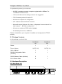
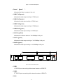
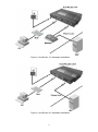
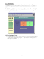
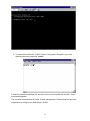
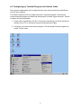
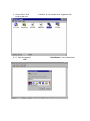
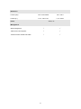
AcerRouter 101/201
User’ s Manual
1
The Federal Communications Commission Statement
This equipment has been tested and found to comply with the limits for a
Class B digital device, pursuant to part 15 of the FCC Rules. These limits are
designed to provide reasonable protection in a residential installation. This
equipment generates, uses and can radiate radio frequency energy and, if not
installed and used in accordance with the instructions, may cause harmful
interference to radio communications. However, there is no guarantee that
interference will not occur in a particular installation. If this equipment does cause
harmful interference to radio or television reception, which can be determined by
turning the equipment off and on, the following measures:
-Reorient or relocate the receiving antenna.
-Increase the separation between the equipment and receiver.
-Connect the equipment into an outlet on a circuit different from that to which the
receiver is connected.
-Consult the dealer or an experienced radio/TV technician for help.
You are cautioned that changes or modifications not expressly approved by the
party responsible for compliance could void your authority to operate the
equipment
This device complies with part 15 the FCC Rules.
Operation is subject to the following two conditions:
(1)This device may not cause harmful interference, and
(2)This device must accept any interference received, including interference that
may cause undesired operation.
2
Table of Contents
THE FEDERAL COMMUNICATIONS COMMISSION STATEMENT................. 2
CHAPTER 1
INTRODUCTION ...................................................................... 4
1.1 ABOUT THIS MANUAL.......................................................................... 4
1.2 ABOUT ACERROUTER 101/201 ................................................................. 5
1.3 FEATURES AND BENEFITS.......................................................................... 5
1.4 APPLICATIONS .......................................................................................... 5
CHAPTER 2
BEFORE YOU START ............................................................. 7
2.1 PACKAGE CONTENTS ................................................................................ 7
2.2 HARDWARE DESCRIPTION ......................................................................... 8
2.2.1 AcerRouter 101 ............................................................................. 8
2.2.2 AcerRouter 201 ............................................................................. 9
2.3 SYSTEM REQUIREMENTS ......................................................................... 10
2.4 ISP REQUIREMENTS ............................................................................... 11
CHAPTER 3
QUICK INSTALLATION .......................................................... 12
3.1 HARDWARE INSTALLATION ....................................................................... 12
3.2 CLIENT-SIDE NETWORK SETTINGS ........................................................... 14
3.3 ACERROUTER 101/201 SETTINGS ........................................................... 18
3.4 TEST ...................................................................................................... 20
3.5 SETTING UP OTHER CLIENT STATIONS ....................................................... 20
CHAPTER 4
ADVANCED CONFIGURATION............................................. 21
4.1 CONFIGURING BY W EB MANAGEMENT ...................................................... 21
4.1.1 Intranet Setting ............................................................................ 21
4.1.2 Modem1 Setting .......................................................................... 23
4.1.3 Modem2 Setting .......................................................................... 28
4.1.4 Dial In Setting .............................................................................. 28
4.1.5 Device Admin Setting.................................................................. 30
4.1.6 Status Monitor ............................................................................. 31
4.2 CONFIGING BY TELNET ............................................................................ 31
4.3 CONFIGURING BY TERMINAL PROGRAM VIA CONSOLE CABLE..................... 33
CHAPTER 5
TROUBLESHOOTING............................................................ 36
APPENDIX A
SPECIFICATIONS................................................................. 38
APPENDIX B
GLOSSARY ........................................................................... 40
3
Chapter 1 Introduction
Congratulations on your purchase of AcerRouter 101/201. This series includes
powerful yet simple communication devices for connecting local area network
(LAN) to the Internet. For those who want to surf on the Internet with limited cost,
AcerRouter 101/201 products undoubtedly provide the most convenient and
economical solution.
1.1 ABOUT THIS MANUAL
The User’ s Manual describes how to set up the connection from LAN to the
Internet using AcerRouter 101/201. This manual assumes that you are familiar
with the basic elements of a computer and are interested in detailed or advanced
information on the AcerRouter 101/201. All instructions and examples in this
manual are given for the AcerRouter 101, but also apply to the AcerRouter
201 product unless specifically noted. It is organized as follows:
Chapter
Content
Introduction
Describes AcerRouter 101/201’ s features and
main applications.
Before you start
Describes the information and environment
needed to configure the AcerRouter 101/201.
Quick Installation
Describes how to install AcerRouter 101/201
quickly for ordinary applications.
Advanced
Configuration
Describes all configuration options for the
AcerRouter 101/201, including configuring the
modems and ISP accounts. This chapter also
contains a command reference section for
procedures such as resetting the server, setting
back to defaults, and changing the server
password.
Troubleshooting
Lists problems and solutions one may encounter
when using the AcerRouter 101/201.
Appendix A
Lists AcerRouter 101/201’ s technical
specifications as a quick reference.
Specifications
Appendix B
Explains words and phrases in this manual.
Glossary
4
1.2 About AcerRouter 101/201
AcerRouter 101/201 provides the most Internet access to multiple users by
sharing one/two dial-up accounts. The outstanding feature of AcerRouter 101 is
the two-serial-port (AcerRouter 201 with one built-in modem and one serial-port)
design as primary and secondary on-demand or dial-in ports. Modem2 port will be
initiated by the system to increase the bandwidth for traffic congestion relief.
Modem2 port will disconnect automatically to save cost when the demand for
service decreases. If there is no request for accessing the Internet after a period of
time, the system will hang up the connection automatically. Simple configuration
gets your AcerRouter 101/201 up and running in minutes.
With all these advance technologies, AcerRouter 101/201 provide a cost effective
solution for your networking need.
1.3 Features and Benefits
Ÿ Support 28.8/33.6/56K modems, ISDN TAs, and leased-line connections
Ÿ Support up to two modem connections simultaneously to boost Internet
access bandwidth
Ÿ Support Dial-On-Demand and auto-disconnect function to save Internet
access cost
Ÿ Support PPP/PAP/CHAP authentication protocol for dial-up identification
Ÿ Support PPP dial-in connection by using standard dial-up program
Ÿ Support DHCP/fixed IP configuration for host IP address assignment
Ÿ Easy setup through web browser or Telnet on any operating system that
supports TCP/IP
Ÿ Compatible with all popular Internet applications
Ÿ Firewall to protect internal hosts from outside intruders
Ÿ Network connection through the built-in 10BASE-T or 100BASE-TX Ethernet
1.4 Applications
There are several applications for AcerRouter 101/201, such as:
Ÿ Sharing IP Address
The AcerRouter 101/201 provides the most Internet utilization to multiple
users by sharing network environment. With only one ISP account, multiple
users on your network can have access to Internet simultaneously.
Ÿ Internet Access
The series supports one or two modem Internet accesses. Users can
choose to link either one or two modems based on their needs. Normally, it
is more economical to use one modem. Yet, if you require more bandwidth
for surfing the Net, using two modems would be faster and more efficient.
With proper configuration, the AcerRouter 101/201 can hook up and drop
5
off the line automatically.
Ÿ Remote Access
The Modem 2 port of AcerRouter 101/201 can support dial-in function for
remote access. Remote users can dial-in and access interior resources
through modem connection. Optional callback function is also provided for
the sake of security.
Ÿ Virtual Server
If you have a fixed IP address, you can setup a virtual host environment.
Internet users can access the target host to get the information by using
Virtual Host function provided by the unit.
Ÿ Security
AcerRouter 101/201 supports firewall security that can deny Internet users
from internal resources. It also can filter internal Internet requests that the
administrator does not wish to serve.
6
Chapter 2 Before You Start
To operate this product, you must have:
Ÿ A 80486 or greater processor computer equipped with a 10Base-T or
10/100Base-T Ethernet card
Ÿ 16-bit, small-font monitor settings or above are suggested
Ÿ TCP/IP network protocol for each PC
Ÿ At least one computer for configuration
Ÿ UTP network cable with RJ-45 connector
Ÿ Microsoft Internet Explorer 4.0 or later, or Netscape Communicator 4.0 or
later browser¡ ]For Web configuration¡ ^
Ÿ At least one modem or ISDN terminal adapter
Ÿ A dedicated phone line or ISDN line
Please verify whether your computer is installed and configured with TCP/IP
properly.
2.1 Package Contents
In this package, you should find:
AcerRouter
101
AcerRouter
201
1
1
Power Adapter
1(AC9V,1A)
1(AC9V,1A)
User’ s Manual
1
1
RS-232 Configuration Cable
(shielded)
1
1
RS-232 Modem Cable (shielded)
2
1
RJ-11 Phone Cable
0
1
Router
2.2 Hardware Description
2.2.1 AcerRouter 101
7
Figure 1. Front Panel Description
Ÿ Power¡ g
] reen¡ ^
Indicates that there is power to the unit.
Ÿ COM1-TxD (green)
Indicates the data output activity of COM1 port
Ÿ COM1-RxD (green)
Indicates the data input activity of COM1 port
Ÿ COM2-TxD (green)
Indicates the data output activity of COM2 port
Ÿ COM2-RxD (green)
Indicates the data input activity of COM2 port
Ÿ LAN-Col (yellow)
Indicates the collision status of 10/100Mbps LAN port
Ÿ LAN-Tx (green)
Indicates the data output activity of 10/100Mbps LAN port
Ÿ LAN-Rx (green)
Indicates the data input activity of 10/100Mbps LAN port
Figure 2. Rear Panel Description
Ÿ COM1
1st RS-232 port connecting with external modem or ISDN-TA
Ÿ COM2
2nd RS-232 port connecting with external modem or ISDN-TA
Ÿ Node
8
10/100Mbps LAN port connecting with PC or Mac
Ÿ Hub
10/100Mbps LAN port connecting with Hub port
Ÿ Console
RS-232 console port operating at 9600-baud
Ÿ AC 9V
External AC power adaptor input
2.2.2 AcerRouter 201
Figure 3. Front Panel Description
Ÿ Power¡ g
] reen¡ ^
Indicates that there is power to the unit.
Ÿ V.90-TxD (green)
Indicates the data output activity of V.90 modem
Ÿ V.90-RxD (green)
Indicates the data input activity of V.90 modem
Ÿ V.90-OH (green)
Indicates the hook status of V.90 modem
Ÿ COM2-TxD (green)
Indicates the data output activity of COM2 port
Ÿ COM2-RxD (green)
Indicates the data input activity of COM2 port
Ÿ LAN-Tx (green)
Indicates the data output activity of 10/100Mbps LAN port
Ÿ LAN-Rx (green)
Indicates the data input activity of 10/100Mbps LAN port
9
Figure 4. Rear Panel Description
Ÿ LINE
V.90 modem RJ-11 for PSTN analog telephone line
Ÿ PHONE
V.90 modem RJ-11 for external telephone set
Ÿ COM2
nd
2 RS-232 port connecting with external modem or ISDN-TA
Ÿ Node
10/100Mbps LAN port connecting with PC or Mac
Ÿ Hub
10/100Mbps LAN port connecting with Hub port
Ÿ Console
RS-232 console port operating at 9600-baud
Ÿ AC 9V
External AC power adaptor input
2.3 System Requirements
Ÿ A 80486 or greater processor computer equipped with a 10Base-T or
10/100Base-T Ethernet card
Ÿ 16-bit, small-font monitor settings or above are suggested
Ÿ TCP/IP network protocol for each PC
Ÿ At least one computer for configuration
Ÿ UTP network cable with RJ-45 connector
Ÿ Microsoft Internet Explorer 4.0 or later, or Netscape Communicator 4.0 or
later browser¡ ]For Web configuration¡ ^
Ÿ At least one modem or ISDN terminal adapter
Ÿ A dedicated phone line or ISDN line
10
2.4 ISP Requirements
Please collect the following information from your ISP before setup:
Ÿ ISP authentication type or script (if not PAP/CHAP)
Ÿ An ISP account which includes ISP dial-up username and password
Ÿ ISP dial-up phone number
Ÿ Your ISP’ s Domain Name Server IP address
Ÿ IP Address and Subnet mask (optional, for fixed IP users only.)
11
Chapter 3 Quick Installation
This Quick Installation is designed to help install the AcerRouter 101/201 to your
network. The instructions included in this section assume you are setting up a new
network.
There are 5 steps to set up the AcerRouter 101/201 product:
1. Hardware Installation¡ GTo set up the hardware connection, power and other
devices.
2. Client-side Network Settings¡ GTo set up the client-side TCP/IP
configuration in order to configure and access the AcerRouter 101/201.
3. AcerRouter 101/201 Setting¡ GTo configure the AcerRouter 101/201 product
using Java compatible web browser or Telnet program.
4. Test¡ G
Use browser to access external web site to check if all settings are
correct.
5. Setting up other clients¡ GTo set up all other client stations in the same
LAN.
3.1 Hardware Installation
The followings are instructions for setting up the AcerRouter 101/201 . Refer to the
illustration below and follow the simple steps to quickly install your AcerRouter
101/201.
12
Figure 5. AcerRouter 101 Hardware Installation
Figure 6. AcerRouter 201 Hardware Installation
13
1. Connect one end of the RS-232 DB25-to-RJ45 cable¡ ]included in the
package¡ ^ to the modem/ISDN TA and the other end to the RJ-45 serial
port labeled COM 1 on the back of the AcerRouter 101. Go to Step 2. For
the AcerRouter 201, connect one end of RJ-11 cable to wall RJ-11 outlet
and the other end to the RJ-11 port labeled "Line" on the back of the
AcerRouter 201. Go to step 4.
Note:
The AcerRouter 101/201 has only one standard 10/100Base-T port.
But there are two connectors – one labeled “ Hub” and one labeled
“ Node” – that users can choose to use.
Only one connector
should be used at one time.
2. Connect phone line to the modem/ISDN TA.
3. Connect power adapter to the modem/ISDN TA and turn on the power. We
suggest that one single modem be connected and configured first, and if an
additional modem is required, repeat the previous procedure for setting up
the first modem/ISDN TA.
4. Use standard “ straight” twist-pair Ethernet cables to connect your current
hub/switch to the “ Hub” port or personal computer to the “ Node” port.
5. Plug the AcerRouter 101/201 power adapter outlet, then plug the power
supply output cable into the power connector on the rear of the unit. The
Power LED should be lit immediately.
3.2 Client-side Network Settings
After installing the AcerRouter 101/201 hardware, please follow the procedures
below to configure the units:
1. Choose a computer in LAN to configure the AcerRouter 101/201. On
Windows 95 desktop, double click “ My Computer” .
Ÿ
Ÿ
14
Ÿ
2. Double click “ Control Panel” .
3. Double click “ Network” . This window appears the related information about
the network interface card which you installed. Please check out if “ TCP/IP”
component is installed or not. If not, click “ Add” , otherwise, go to Step 6.
15
4. Double click “ Protocol” .
5. On the left side of the window, choose “ Microsoft” , and then select “ TCP/IP”
component on the right side. After TCP/IP component is completely installed,
click “ OK” .
16
6. Double click “ TCP/IP” component.
7. The TCP/IP Properties window appears. If there is no DHCP server in the
same Network, click “ IP Address” and select “ Obtain IP address
automatically” item. Meantime, ignore the Gateway and DNS settings because
the system will configure them automatically.
17
Note¡ G
If there is any other DHCP server in the Network, please select “ Specify an IP
address” and use the default value “ 192.168.1.***”¡ ]*** is between 2 and 252¡ ^
, set
Subnet Mask “ 255.255.255.0” , Gateway IP “ 192.168.1.1” and DNS for configuration.
After finishing TCP/IP set up, reboot the computer and run the browser to configure the
AcerRouter 101/201. Afterwards, set up other PC in the LAN according to above
procedures.
3.3 AcerRouter 101/201 settings
1. Start your web browser (Netscape Navigator 4.0 or Microsoft Explorer4.0 later or
other Java compatible browser) and type 192.168.1.1 in the address and press
“ ENTER” key on your keyboard. The “ Username and Password Required”
window will pop up. Leave the User Name blank and fill in the Password “ admin” .
Then click “ OK” to enter Web Management.
The Quick Setup window pops up consequently.
18
Note: In Netscape Communicator 4.0, after popping up for a while, the Quick
Setup window will be hidden behind the Netscape main window. Minimize the
Netscape main window if wish to see the Web Management page.
2. Select “ Enable” (default value) to key in the required information for Modem 1.
Note: Modem2 Settings are similar to the Modem1’ s. Repeat step 3 if wish to
install Modem2.
3. For most ISP, it’ s ok to select PPP. Select the applicable ISP Name from the
drop-down box.
4. For most PPP dial-up account, below 4 parameters are needed. Fill the ISP
phone number, DNS IP, User ID and Password respectively. The information
should be provided by ISP as soon as you applied the account.
5. In Intranet Setting, enter the default value 192.168.1.1 and Subnet Mask
255.255.255.0, or select one applicable from the drop-down box.
6. Check all the values and click “ Save” to save the data and logout setup.
19
3.4 Test
After finishing the AcerRouter 101/201 setup, run another browser and key in any
external web site address like www.yahoo.com to see if the modem dials properly.
Once the Link LED is on, the Internet connection is successfully established.
Otherwise, refer the Troubleshooting section for further instructions.
3.5 Setting Up Other Client Stations
Follow the 3.2 Client-Side Network Settings to set up other client stations. If you use
fixed IP configuration, be careful not to assign the same IP to different computers.
20
Chapter 4 Advanced Configuration
After the client computer is well configured, you can use any Java supported browser
or Telnet program to configure the AcerRouter 101/201 series.
4.1 Configuring by Web Management
The Main Menu includes Quick Setup is for quick installation as described in Chapter 3.
The Advanced Menu includes Intranet Setting, Modem1 Setting, Modem2 Setting, DialIn Setting, Device Admin, and Status Monitor.
4.1.1 Intranet Setting
Click ” Intranet Setting” in the Advanced menu as below.
IP Settings
Check the IP Address and Subnet Mask for the AcerRouter 101/201. If you wish to use
the AcerRouter’ s DHCP server function, enable Dynamic IP address and the number
of users. Remember if you have dial-in users, the last two IP addresses are
automatically left for them to avoid overlapping with the dial-out users’ IP Addresses.
21
Filter
In the filter menu, IP Address Filter prevents some interior members to browse the
Internet via AcerRouter 101/201. You may add up to five sets of IP address on the
Filtered Private IP Address field.
Service Filter allows the prevention of all users from accessing any restricted service
on the Internet. You may add up to five services on the Filtered Private Ports field.
Virtual Server
Virtual server is setting up public services group interior so as for allowing Internet
users to access. You must have a fixed IP to utilize this function. For example, If you
set "80(WWW HTTP) in Service field and 192.168.1.2 in IP Address field, then all
WWW request from outside user will be transferred to 192.168.1.2. The Gateway of
servers must be set on 192.168.1.1
You may use this function to establish web server or FTP server via AcerRouter
101/201 for Internet users to access. Only enter the IP Address provided by ISP,
Internet users can get all the information from 192.168.1.2.
22
4.1.2 Modem1 Setting
Firstly, enable Modem1 Dial-Out Service before setup.
General
Select the Line Type and the Baud Rate from the drop-down box. It is suggested that
the Baud Rate should be about four times of maximal speed of your modem. Enter the
necessary ISP and Authentication information and click on the “ save” .
23
Note:
If your ISP account needs Login Script, click the “ Script” button and the screen below
will pop up. Enter the necessary script file to connect to the ISP. The following is a
sample script file with the proper syntax and the meaning of the command.
24
~~” ogin:” ” Neil” ~~” word:” ” a5831010”
Command
Description
~~
Wait for two seconds before executing the next script line.
The number of “ ~” stands for the time of seconds.
“ ogin:”
“ Neil”
~~“ word”
“ a5831010
”
The double quotes stands for sending/receiving the
message. The ‘ ogin:’ is part of ‘ login:’ to avoid
mistakes caused by lowercase/uppercase of the beginning
word “ L” . As the example, “ ogin:” means to verify that the
ISP is sending login message.
After receiving the login requirement from ISP, you can
enter your login name ‘ Neil’ within double quotes to send
the message. Please note that the login name is provided
by ISP.
‘ Word’ is part of ‘ password’ . After sending out the login
user name, you may wait two seconds for the ISP to ask
your password.
After receiving the inquiry from your ISP, please enter your
password within double quotes to send the message.
Please note that the password is provided by the ISP.
25
IP Address
This page indicates if you would like to get a dynamic IP or a fixed IP from ISP. If you
wish to have a fixed IP, please also enter the IP address and the DNS IP.
Advanced
This page is to verify the configuration of your modem. Please refer to your modem’ s
user’ s manual to fill in the required information.
Select the Dial On Demand to enable the Dial-On-Demand function. You can also key
in the idle timer and retry timer of Modem1 Internet access.
Enable the Bandwidth Allocation so that
Modem2 will dial-up when the networking
26
traffic exceeds the setup threshold.
Note: About ISDN TA Setup
Unlike most modems, ISDN initial strings vary between different ISDN TAs and there is
no “ Standard ISDN TA” initial string. If your ISDN TA is not listed in the modem
selection list, you must find out what your ISDN TA initial string is. Your ISDN TA’ s
initial string should be listed in your ISDN TA user’ s manual. There are probably many
initial strings listed for your ISDN TA. The one you are looking for is Asyn-to-Sync PPP
(Asynchronous to Synchronous PPP). You can enter this initial string if you would like
to use only one channel of your ISDN TA. If you would like to bundle both channels of
your ISDN TA together, you need to use a different initial string called Multilink-PPP.
You should also verify that your ISDN TA supports the Dial-up string ATDT. Most ISDN
TAs will support ATDT and usually the rest will support ATD or ATDI.
Please also note that to bundle the two channels of your ISDN TA together, you must
enter the two phone numbers in the Telephone Number.
27
4.1.3 Modem2 Setting
Settings of Modem2 are similar to Modem1. Please refer to Modem1 Settings for
setting Modem2.
4.1.4 Dial In Setting
Dial-in User Account
To configure computers for remote dial-in access, please select “ Enable” radio button
to initiate Modem2 Dial-in Service. Enter the ID and Password of dial-in users. The
default ID and Password setting for User1 is “ guest” and “ password” and up to three
users are allowed to use dial-in access.
28
Callback
Dial-in callback function is provided for AcerRouter 101/201. Set the call back time and
the AcerRouter 101/201 will automatically call back after receiving dial-in inquiries to
make sure that the user is on the dial-in list. Note that the phone charge will be
transferred to you if you enable the callback function.
29
4.1.5 Device Admin Setting
In the Device Admin Setting, you may change the password or reset the device. Select
“ Yes” to the Factory defaults function will reset all the settings previously configured
and return to the default configurations.
30
4.1.6 Status Monitor
This page provides working information of the working status of the AcerRouter
101/201. You can click on the DHCP Clients Table button to check on the DHCP IP
table.
The DHCP Active IP Table lists all clients that get IP from the AcerRouter 101/201. To
see the latest IP distribution information, click the Refresh button on the upper left
corner to update the information.
4.2 Configuring by Telnet
1. At MS-DOS Prompt, execute “ telnet 192.168.1.1” command to enter AcerRouter
101/201 Telnet Configuration Program. ¡ ]Use respective Telnet program in
other operating systems.¡ ^
31
2. To enter the AcerRouter 101/201 Telnet Configuration Program, key in the
default supervisor password “ admin” .
3. After the password certified OK, the main menu of the AcerRouter 101/201 Telnet
commands appears.
The structure of commands is similar to web management. Please follow the previous
explanation to configure the AcerRouter 101/201.
32
4.3 Configuring by Terminal Program via Console Cable
The console configuration can be used when the user cannot access the AcerRouter
101/201 from network.
This section explains how to configure and use a Terminal program. The terminal
communications program provided with Windows 95 is called “ HyperTerminal” . Please
configure as instructed below:
1. Power off the AcerRouter 101/201. Connect the AcerRouter 101/201’s serial port
directly to your PC’ s serial port using the enclosed serial cable.
2. Configure your terminal emulation program. Find the HyperTerminal program as
below. Click to enter.
33
3. Check if the “ Null
build a new one.
4. A New Connection”
“ OK” .
” is built-in. If not, double click Hypertrm.exe”
“ Null Modem” in the Name field
5. The “ Phone Number” window appears. Make sure that the “ Connect using” box
shows the one you have connected the serial cable to.
6. Click the “ OK” button, and you should see a screen as below. Change the
settings as the screen shows.
7. Click “ OK” when finished.
8. Power on the AcerRouter 101/201 by plugging in the power adapter. The built-in
configuration program will start automatically. Press “ Enter” and the main menu
appears.
The structure of commands is similar to web management. Please follow the screen
35
explanation to configure the AcerRouter 101/201.
Chapter 5 Troubleshooting
This chapter provides the solutions to problems occuring during installation and
operation of the AcerRouter 101/201. Please check the following to solve problems.
Problem & Symptom
Possible cause & Solution
HardwareThe LAN Tx/Rx LED is off
Check all the connections and make sure that they are well connected.
Make sure that your hub/switch is correctly connected to “ Hub” , or your PC to “ Node” .
“ Hub” and “ Node” can not be used at the same time.
Make sure that your Ethernet card is installed properly.
Make sure all the physical connections are well-connected and the Modem is powered
on.
Make sure a working phone line is connected to the Modem.
Modem is not able to dial out
The number may need to be added with prefix such as “ 0,” to get an outside line. The
comma stands for the connection waiting time.
I Can’ t browse to the IP Gateway Check the TCP/IP setup on your PC.
Run “ winipcfg” under Windows 95/98 prompt DOS or
run “ Ipconfig” under Windows NT prompt DOS. The PC should have an IP address of
192.168.1.x (where “ x” is from 1 to 254.).
If you use fixed IP, you have to set client station IP address in the range of 192.168.1.2
~ 192.168.1.252 except 192.168.1.100 ~ 192.168.1.149, default gateway as
192.168.1.1 and DNS IP as your ISP’ s DNS IP.
If the computer has previously used Dial-up networking for Internet access, you have to
make the following changes:
l
Click Start, Setting and Control Panels
l
Double click the Internet icon and then click Connection tab
l
Select Connection to the internet using a local area network
l
Click OK to finish.
36
AcerRouter 101/201 and Modem
Modem can dial out, but won’ t
connect to the ISP
Check the initialization string set up. Be sure to
power off and power on the Modem after changing the string.
Basically default AT command is “ AT&F” and is available for most modems, but some
modems had its own initial AT command due to changeable serial port rate and you
can find this information on their user’ s manual. (For Example, US Robotics modem
initial string is “ AT&F1B1 )
For no dial tone telephone system, your initial AT command should add “ X1” as
“ AT&FX1”
Test the Modem in Diagnostics window of Telnet.
You can also use Ping command in MS-DOS mode to verify the network connection:
l
Ping 127.0.0.1 to see if the TCP/IP stack is properly configured.
l
works.
Ping gateway IP (Default: 192.168.1.1) to check if the internal link of network
l
Ping DNS IP and observe whether the modem will dial or not, to check the
external link and modem connection.
l
works.
Ping a Internet domain name (Example: www.yahoo.com) to see if DNS
When dialing into the AcerRouter Make sure that you are on the AcerRouter 101/201 Dial-in User list.
101/201, the Modem does not
Modem 2 cannot be enabled.
seem to connect.
Check the rear panel of the device, the MODEM 2/CONFIG Switch must be set on the
MODEM 2.
If the Bandwidth-on-demand is set on the bandwidth allocation, lower down the
percentage of MODEM1 in the rule dialogue¡ ]
the default setting is at 50%¡ ^.
Miscellaneous
I cannot get IP from AcerRouter
101/201. I have another DHCP
server on my LAN
If there are no Internet access for your network environment, we suggest that you
disable AcerRouter 101/201 DHCP server on the Intranet page. If your LAN can access
the Internet in default, we suggest that you disable your pre-existing DHCP server
services or separates them into two different segments.
37
Appendix A Specifications
101
201
IEEE 802.3 10BASE-T
√
√
IEEE 802.3u 100BASE-TX
√
√
PPP, TCP/IP, DHCP, DNS
√
√
CHAP/PAP, SNMP
√
√
RS-232/Modem RJ-45 connector
2
1
V.90 56kbps RJ-11 connector
0
1
RS-232/Console RJ-45 connector
1
1
1
1
Windows Dial-up Network
√
√
Trumpet
√
√
PPP compatible application
√
√
Power
√
√
Link/Activity for WAN/LAN ports
√
√
Collision for LAN port
√
×
Standards Compliance
WAN Interface
LAN Interface
10BASE-T/100BASE TX RJ-45 port
Support Dial-in Client
LED Display
Environments
0~50¢ J(32~122°F)
Operation Temperature
-20~70¢ J(-4~158°F)
Storage Temperature
Humidity
0~90%
38
Dimension
LxWxH (mm)
181 x 125 x 38.26
181 x 125 x
LxWxH (in.)
7.13 x 4.92 x 1.51
7.13 x 4.92 x
AC9V, 1A
Power
Management
Web management
√
√
Telnet from LAN computer
√
√
Terminal control via RS-232 cable
√
√
39
Appendix B Glossary
DHCP
DHCP is a protocol for automatic IP configuration. Client side computer can get one IP
from DHCP server automatically. Using DHCP can save the effort of setting IP for
every LAN computers.
Dial-in
Dial in is the function for remote user to access office LAN by Modem/ISDN TA
connection. Just like you dial up to ISP, Gateway Hub can act as a small ISP that
telecommuter and travelling employee can access LAN using standard dial up
program.
Dial-up Access
Refers to connecting a device to a network via a modem and a public telephone
network. Dial-up access is really just like a phone connection, except that the parties at
the two ends are computer devices rather than people. Because dial-up access uses
normal telephone lines, the quality of the connection is not always good and data rates
are limited, but new technologies such as ISDN are providing faster rates.
An alternative way to connect two computers is through a leased line, which is a
permanent connection between two devices. Leased lines provide faster throughput
and better quality connections, but they are also more expensive.
Domain Name
A name that identifies one or more IP addresses. For example, the domain name
microsoft.com represents about a doze IP addresses. Domain names are used in
URLs to identify particular Web pages. For example, in the URL
http://www.pcwebopedia.com/index.html, the domain name is pcwebopedia.com.
IEEE
Abbreviation of Institute of Electrical and Electronics Engineers, pronounced I-triple-E.
Founded in 1884, the IEEE is an organization composed of engineers, scientists, and
students. The IEEE is best known for developing standards for the computer and
electronics industry. In particular, the IEEE 802 standards for local-area networks are
widely followed.
Internet
A global network connecting millions computers. As of 1998, the Internet has more
than 100 million users worldwide, and that number is growing rapidly. More than 100
countries are linked into exchanges of data, news and opinions.
40
Intranet
A network based on TCP/IP protocols (an internet) belonging to an organization,
usually a corporation, accessible only by the organization's members, employees, or
others with authorization.
IP Address
An identifier for a computer or device on a TCP/IP network. Networks using the TCP/IP
protocol route messages based on the IP address of the destination. The format of an
IP address is a 32-bit numeric address written as four numbers separated by periods.
Each number can be zero to 255. For example, 1.160.10.240 could be an IP address.
ISDN
Abbreviation of integrated services digital network, an international communications
standard for sending voice, video, and data over digital telephone lines. ISDN requires
special metal wires and supports data transfer rates of 64 Kbps (64,000 bits per
second).
ISP
Short for Internet Service Provider, a company that provides access to the Internet. For
a monthly fee, the service provider gives you a software package, username, password
and access phone number. Equipped with a modem, you can then log on to the
Internet and browse the World Wide Web and USENET, and send and receive e-mail.
Local Area Network (LAN)
A computer network that spans a relatively small area. Most LANs are confined to a
single building or group of buildings. However, one LAN can be connected to other
LANs over any distance via telephone lines and radio waves. A system of LANs
connected in this way is called a wide-area network (WAN)
MAC Address
Short for Media Access Control address, a hardware address that uniquely identifies
each node of a network. In IEEE 802 networks, the Data Link Control (DLC) layer of
the OSI Reference Model is divided into two sublayers: the Logical Link Control (LLC)
layer and the Media Access Control (MAC) layer. The MAC layer interfaces directly
with the network media. Consequently, each different type of network media requires a
different MAC layer.
PPP
PPP (Point-to-Point protocol) is a communications protocol for transmitting information
41
over standard telephone lines. A PPP account is a dial-up account used to connect to
the Internet. It is a dial-up account actually calls another computer to gain Internet
access.
PAP/CHAP ISP
PAP stands for Password authentication protocol. CHAP means Challenge handshake
authentication protocol. Most ISP use either one for user identification. If your ISP
doesn’ t support these two protocols, contact ISP for authentication script. You have to
key in script to IP Gateway.
TCP/IP
Acronym for Transmission Control Protocol/Internet Protocol, the suite of
communications protocols used to connect hosts on the Internet. TCP/IP uses several
protocols, the two main ones being TCP and IP.
Telnet
A terminal emulation program for TCP/IP networks such as the Internet. The Telnet
program runs on your computer and connects your PC to a server on the network. You
can then enter commands through the Telnet program and they will be executed as if
you were entering them directly on the server console. This enables you to control the
server and communicate with other servers on the network. To start a Telnet session,
you must log in to a server by entering a valid username and password.
42
Product Limited Warranty
Acer Netxus Incorporated (ANI) warrants its product to be free from defects in
materials and workmanship, under normal use and service, for the following lengths of
time form the date of purchase from ANI or its Authorized Resellers.
Router Product *2 year
All products with limited lifetime warranty have a standard two-year warranty. This
warranty does not cover the product if it is damaged by abuse, accident, misuse,
improper installation, or improper testing. If a product does not operate as warranted
during the applicable warranty period, ANI shall, at its option and expense, either repair
the defective product or part returned to ANI, or deliver to customer and equivalent
product or part to replace the defective item. Definitely, all products that are replaced
will become the property of ANI. Replacement products may be new or reconditioned.
ANI shall not be responsible for any software, firmware, information, or memory data of
customer contained in, stored on, or integrated with any products returned to ANI
pursuant to any warranty. Before you obtain warranty service, you must request an
RMA (Return Materials Authorization) number by calling, faxing or writing ANI’ s
Customer Service Department at the numbers listed below. You must use the original
container (or the equivalent) and Pay the shipping charge.
ANI SHALL NOT BE HELD LIABLE FOR INCIDENTAL, CONSEQUENTIAL,
INDIRECT, SPECIAL OR RUNTIME DAMAGES OF ANY KIND; OR FOR LOSS OF
REVENUE, LOSS OF BUSINESS, OR OTHER FINANCIAL LOSS ARISING OUT OF
OR IN CONNECTION WITH THE SALE, INSTALLATION, MAINTENANCE, USE,
PERFORMANCE, FAILURE, OR INTERRUPTION OF ITS PRODUCTS, EVEN IF ANI
OR ITS AUTHORIZED DEALER HAS BEEN ADVICED OF THE POSSIBILITY OF
SUCH DAMAGES.
Model Name
Series No. (S/N)
Purchase Date
(Authorized Distributions’ or Resellers’ Stamp)
43
If you purchased this product in the UNITED STATES, some states do not allow the limitation or exclusion of liability for
incidental consequential damages, so the above limitation may not apply to you.
Contact us:
Acer UK Limited
Tel: 44-1628-533422
Fax: 44-1628-524071
http://www.aceruk.co.uk
Acer Computer International Ltd.
Taiwan Branch
Tel: 886-2-2713 9099 ext.7293
Fax: 886-2-2718 4895
http://www.aci.acer.com.tw
Acer Computer France S.A.R.L.
Tel: 33-1-4817 4040
Fax: 33-1-4817 4089
Acer America Corporation
Tel: 1-408-432 6200
Fax:1-408-922 2993
http://www.acer.com/aac
Distribution/Information
Hotline: 1-800-369 6736
Fax: 1-408-432 0496
http://www.acer.com/aac/aod
Acer Computer GmbH
Tel: 49-4102-488-0
Fax: 49-4102-488-101
Dealers' Information
Hotline: Germany 0180-3234781
End users' Information
Hotline: Germany 0180-5009898
Acer Latin America Inc.
Tel: 1-305-392 7200
Fax:1-305-392 7216
Acer Computer Iberica, S.A.
Tel: 34-3-499-0303
Fax: 34-3-499-0483
Acer Japan Corporation
Tel: 81-3-5434 7373
Fax: 81-3-5434 7533
Acer Computer B.V.
Tel: 31-73-645 9645
Fax: 31-73-645 9599
44