1
main
menu
local
search
global
search
operation
troubleshooting
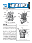
MACK
"FOXHEAD"
CUMMINS
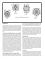
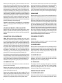
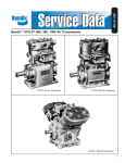
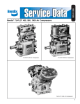
VARIOUS COMPRESSOR MOUNTINGS
MACK
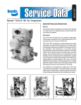
OPERATION
The compressor is driven by the vehicle engine and is
operating continuously while the engine is running. Actual
compression of air is controlled by the compressor unloading
mechanism and the governor. The governor is generally
mounted on the compressor and maintains the brake system
air pressure to a preset maximum and minimum pressure
level.
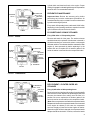
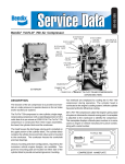
INTAKE AND COMPRESSION OF AIR (LOADED)
During the down stroke of the piston, a slight vacuum is
created between the ton of the piston and the head, causing
the flat circular inlet valve to move up and off its seat. (Note
the flat square discharge valve remains on its seat.)
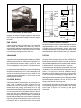
Atmospheric air is drawn through the air strainer by the open
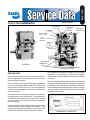
inlet valve and into the cylinder (see Fig. 1). As the piston
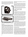
begins its upward stroke, the air that was drawn into the
cylinder on the down stroke is being compressed. Air
pressure on top of the inlet valve plus the force of its spring,
returns the inlet valve to its seat. The piston continues the
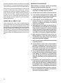
upward stroke and compressed air then flows by the open
discharge valve, into the discharge line and on to the
reservoirs (see Fig. 2). As the piston reaches the top of its
stroke and starts down, the discharge valve spring and air
pressure in the discharge line returns the discharge valve to
its seat. This prevents the compressed air in the discharge
line from returning to the cylinder bore as the intake and
compression cycle is repeated.
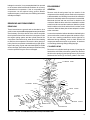
NON-COMPRESSION OF AIR (UNLOADED)
When air pressure in the reservoir reaches the cut-out setting
of the governor, the governor allows air to pass from the
2
DETROIT
DIESEL
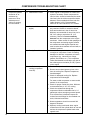
reservoir into the cavity beneath the unloader pistons. This
lifts the unloader pistons and plungers. The plungers move
up and hold the inlet valves off their seats (see Figure 3).
With the inlet valves held off their seats by the unloader
pistons and plungers, air is pumped back and forth between
the two cylinders. When air is used from the reservoir and
the pressure drops to the cut-in setting of the governor, the
governor closes and exhausts the air from beneath the
unloader pistons. The unloader saddle spring forces the
saddle, pistons and plungers down and the inlet valves return
to their seats. Compression is then resumed.
LUBRICATION
Since all Tu-Flo 700 Compressors are connected to the
engine’s pressurized oil system, a continuous flow of oil is
provided to the compressor, which is eventually returned to
the engine. Oil is fed into the compressor in various ways,
for example: through the rear end cover, the drive end of the
crankshaft or through the front flange adapter. An oil passage
in the crankshaft conducts pressurized oil to the precision
sleeve main bearings and to the connecting rod bearings.
Splash lubrication of the cylinder bores, connecting rod wrist
pin bushings, and the ball type main bearings, on some
models, is obtained as oil is forced out around the crankshaft
journals by engine oil pressure.
COOLING
Air flowing through the engine compartment from the action
of the engine’s fan and the movement of the vehicle assists
in cooling the crankcase. Coolant flowing from the engine’s
cooling system through connecting lines enters the
compressor and flows through the internal passages in the