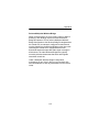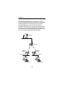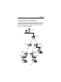
1
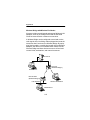
User’s Guide
High Performance Wireless
Bridge Solutions
for Ethernet and Token Ring
Products supported:
BRE100 and BRE500 Series (ETSI Compliant) and
BR100 and BR500 Series (North American)
DOC-710-004496-B0
Aironet Wireless Communications, Inc. • 3875 Embassy Parkway
Akron, Ohio 44333-8357
www.aironet.com
Aironet Wireless Communications, Inc.
No part of this document may be reproduced or transmitted in any means, electronic or mechanical, for any purpose, without the written permission of Aironet.
Information in this document is subject to change without notice. Aironet makes
no representation or warranties with respect to the contents of this manual and
specifically disclaims any express or implied warranties of merchantability or
fitness for any particular purpose.
© 1998 Aironet Wireless Communications, Inc.
All rights reserved.
BRE101TM, BRE105TM, BRE110TM, BRE501TM, BRE520TM, BRE530TM, BR100TM,
BR110TM, BR120TM, BR130TM, BR500TM, BR510TM, BR520TM, BR530TM, and
AironetTM are trademarks of Aironet Wireless Communications, Inc.
Other trademarks used are properties of their respective owners.
Printed in USA
DOC-710-004496-B0
Table of Contents
Introduction ........................................................ 1-1
Purpose of the Manual .................................. 1-1
Safety Information ......................................... 1-2
Snap-On Antenna ................................... 1-3
High Antennas ........................................ 1-3
Warning for Laptop User ........................ 1-3
Antenna Options ........................................... 1-4
Before You Start ............................................ 1-5
Determining Bridge Location ......................... 1-5
Building to Building Connectivity ............ 1-6
Line of Site .............................................. 1-6
Terminology .................................................. 1-8
Installation .......................................................... 2-1
Installing the Antenna .................................... 2-1
Installing the Console Port Cable .................. 2-3
Installing the Ethernet Connection ................ 2-4
Installing the Token Ring Connection ........... 2-6
Attaching the AC/DC Power Pack and
Powering On Ethernet or Token Ring
Wireless Bridge ............................................. 2-7
Viewing the Indicator Displays ...................... 2-8
Top Panel Indicators ............................... 2-8
Back Panel Indicators (Ethernet Only) .. 2-10
Configuration ..................................................... 3-1
Accessing the Console System ..................... 3-1
Configuring the Wireless Bridge .................... 3-2
SSID Identifier (SSID) ............................. 3-2
Assigning an IP Address ........................ 3-3
Verifying Association .............................. 3-3
Appendix A .........................................................A-1
System Configurations .................................. A-1
Point-to-Point Wireless Bridge ................ A-2
Supporting Mixed Network Topologies ......... A-3
Point-to-Multipoint Wireless Bridge ........ A-5
Infrastructure Extension with Repeaters.. A-7
Wireless Bridge with Wireless
End Nodes............................................... A-8
Appendix B..........................................................B-1
Manufacturers Federal Communication
Commission Declaration of Conformity
Statement....................................................... B-1
Department of Communications–Canada
Canadian Compliance Statement .................. B-5
European Telecommunications Standards
Institute Statement of Compliance
Information to User......................................... B-6
Appendix C .........................................................C-1
Technical Reference Manual ........................C-1
Communications ...........................................C-1
Web Site ........................................................C-1
Introduction
Introduction
Purpose of the Manual
The purpose of this User’s Guide is to allow you to easily
install and initially configure your Aironet Wireless Bridge.
Aironet Wireless Bridges enable you to connect two or
more Token Ring and/or Ethernet networks to create a
single virtual LAN. Workstations on each LAN can
communicate with each other through the Wireless Bridge
connection if they are on the same physical LAN.
When connecting two or more LANs, each LAN uses an
Aironet Wireless Bridge and an antenna to transmit and
receive information. Each RF based Wireless Bridge unit is
connected to the LAN. A Wireless Bridge appears as a
single network node on the wired LAN. It performs routing
functions by moving packets from the wireless LAN to
remote workstations on the radio network. Aironet Wireless
Bridges utilize Direct Sequence Spread Spectrum (DSSS)
technologies in the 2.4 GHz frequency band.
For detailed technical and configuration procedures, see
the Technical Reference Manual document number
710-004494.
1-1
Introduction
Safety Information
The FCC with its action in ET Docket 96-8 has adopted a
safety standard for human exposure to radiated frequency
(RF) electromagnetic energy emitted by FCC certified
equipment. The Aironet products meet the uncontrolled
environmental limits found in OET-65 and ANSI C95.1,
1991. Proper operation of this radio according to the
instructions found in this manual will result in the user
exposure to be substantially below the FCC recommended
limits.
®
U
®L
LISTED
•
Do not touch or move antenna(s) while the unit is
transmitting or receiving.
•
Do not hold any component containing the radio such
that the antenna is very close or touching any exposed
parts of the body, especially the face or eyes, while
transmitting.
•
Do not operate a portable transmitter near unshielded
blasting caps or in an explosive environment unless it
is a type especially qualified for such use.
•
Do not operate radio or attempt to transmit data unless
the antenna is connected, if not, the radio may be
damaged.
1-2
Introduction
Snap-On Antenna
Always orient antenna such that it is at least 5 cm
(2 inches) away from your body.
High Gain Antennas
High gain wall mount or mast mount antennas are
designed to be professionally installed and should be
located at a minimum distance of 30 cm (12 inches) or
more from your body. Please contact your professional
installer, VAR, or antenna manufacturer for proper
installation requirements.
Warning for Laptop User
In order to comply with the FCC RF exposure limits, it is
recommended when using a laptop with the snap-on
antenna, that the antenna should not be positioned
closer than 5 cm (2 inches) from your body or nearby
persons for extended periods of time while it is transmitting (or operating). If the antenna is positioned less than
5 cm (2 inches) from the user, it is recommended that
the user limit exposure time or engage the power
saving features of the Aironet radio to reduce RF
exposure. See the Technical Reference Manual for
proper operation of power savings mode.
1-3
Introduction
Antenna Options
Aironet Bridge Solutions have been packaged to provide
wide area bridge connectivity in accordance with regulatory
rules and regulations. Aironet has designed the product
packages to provide optimal performance, measured by
throughput and range, while maintaining compliance with
various regulatory agencies around the world.
Approved antennas for use with each product are listed
below:
•
BRE101, BRE501, BR110, and BR510
5.2 dBi Omni directional antenna*
6 dBi Patch antenna*
•
BRE105, BRE505, BRE520, BR120, and BR520
12 dBi Omni directional antenna**
13.5 dBi Yagi antenna**
•
BRE110, BRE510, BRE530, BR130, and BR530
21 dBi parabolic dish antenna
*
Can be used with the BRE105, BRE505, BRE520,
BRE110, BRE530, BR110, BR120, BR130, BR520,
and BR530 Series although range will be reduced.
**
Can be used with the BRE110, BRE530, BR120
BR130, and BR530 Series although the maximum
range of the Bridge System will be reduced.
Aironet offers Bridge Packages and a variety of antenna
options to satisfy varying communication requirements
often dictated by premise considerations.
1-4
Introduction
Before You Start
After unpacking the system, make sure the following items
are present and in good condition.
•
Wireless Bridge (Ethernet or Token Ring model)
•
Power Pack. The power pack will be either 120VAC/
60Hz or 90-264VAC/47-63Hz to 12-18VDC, whichever
is appropriate for country of use.
•
Lightning Arrestor (Bridge Package option)
•
Mounting Kit
•
Low Loss Antenna Cable
•
Appropriate Directional Antenna (Bridge Package
option)
If any item is damaged or missing, contact your Aironet
supplier. Save all shipping and packing material in order to
repack the unit should service be required.
Determining Bridge Location
Before beginning installation and configuration, determine
where you want the Aironet Wireless Bridge located.
Because the unit is a radio device, decisions must be made
regarding unit and antenna location to ensure optimum
radio range and throughput performance.
1-5
Introduction
Building to Building Connectivity
Radio ranges for building to building connections are
determined by antenna elevation, path clearances, and
line-of-site considerations. To maximize the range of
your building to building connections, the antenna
should be as high as possible.
Line of Site
A clear line of sight must be maintained between
Wireless Bridge antennas. Any obstructions may
impede the performance or prohibit the ability of the
Wireless Bridge to transmit and receive data.
Directional antennas should be placed at both ends at
appropriate elevation with maximum path clearance.
100 Series Wireless Bridge (2 Mbps)
Bridge
Range
Antenna
BRE115 (ETSI)
BR110
1 Km
2 Miles
6 dBi patch
BRE120 (ETSI)
BR120
5 Km
7 Miles
13.5 dBi Yagi antenna
BRE130 (ETSI)
BR130
10 Km
19 Miles
21 dBi parabolic dish
1-6
Introduction
500 Series Wireless Bridge (11 Mbps)
Bridge
Range
Antenna
BRE515 (ETSI)
BR510
1 Km
1 Miles
6 dBi patch
BRE520 (ETSI)
BR520
2 Km
3 Miles
13.5 dBi Yagi antenna
BRE530 (ETSI)
BR530
5 Km
8 Miles
21 dBi parabolic dish
1-7
Introduction
Terminology
When configuring your system, and when reading this
manual, keep in mind the following terminology:
Infrastructure – The wireless infrastructure is the
communications system that combines Aironet Bridges,
mobile nodes and fixed nodes. Aironet Bridges within the
infrastructure can be either root units, which are physically
wired to the LAN backbone, or can act as wireless repeaters. Other RF enabled devices serve as fixed nodes or
mobile nodes.
Root Unit – The root unit is an Aironet Bridge that is
located at the top, or starting point, of a wireless infrastructure. The root unit provides the physical connection to the
wired LAN (such as Ethernet or Token Ring) and contains
configuration information in its association table that covers
all nodes in the infrastructure.
Repeater – A repeater is an Aironet Bridge that extends the
radio range of the infrastructure. A repeater is not physically
attached to the wired LAN, but communicates via radio to
another Bridge, which is either a root unit or another
repeater.
End Node – A radio node that is located at the end of the
Network Tree.
1-8
Introduction
Parent/Child Node – Refers to the relationships between
nodes in the wireless infrastructure. The complete set of
relationships is sometimes described as a Network Tree.
For example, the Aironet Bridge (at the top of the tree)
would be the parent of the end nodes. Conversely, the end
nodes would be the children of the Aironet Bridge.
Association – Each root unit or repeater in the
infrastructure contains an association table that controls
the routing of packets between the Bridge and the wireless
infrastructure. The association table maintains entries for
all the nodes situated below the Aironet Bridge on the
infrastructure including repeaters and radio nodes.
1-9
Introduction
1-10
Installation
Installation
This section describes the procedures for installing the
Aironet Wireless Bridge.
Installing the Antenna
Before installing your Bridge System, we recommend that
you test the Bridge using the 2.2 dBi dipole antenna
included in your package. Once testing is completed, install
your Wireless Bridge for use with the appropriate antenna
for your application using the following the instructions.
NOTE: The lightning arrestor is available in the Bridge
Package option or may be purchased separately.
1. With the unit powered off, attach the lightning arrestor
to the antenna connector.
10Base5
10BaseT
10Base2
Ethernet
UTP
STP
Token Ring
2-1
Installation
NOTE: Do not over-tighten; finger tight is sufficient.
Position the antennas vertically for best omni-directional
signal reception.
2. Connect the lightning arrestor to one end of the low loss
antenna cable.
NOTE: The lightning arrestor should be connected to the
antenna connector on the Wireless Bridge. The lightning
arrestor is added to provide surge protection to the Bridge
in the event of voltage surges as a result of a lightning
strike.
3. Connect the antenna to the other end of the low loss
antenna cable. Mount the Bridge antenna at an appropriate elevation to ensure maximum path clearance and
line of sight considerations.
NOTE: Due to FCC and DOC Regulations, the antenna
connectors on the Aironet Bridge are of reverse polarity to
the standard TNC connectors.
2-2
Installation
Installing the Console Port Cable
1. Attach the Console Port cable to the serial port. Attach
the other cable end to the serial port on a terminal or a
PC running a terminal emulation program. Use a 9-pin
male to 9-pin female straight through cable.
NOTE: This connection is required for setting up initial
configuration information. After configuration is
completed, this cable may be removed until additional
configuration is required via the serial port.
2. Set the terminal to 9600 Baud, No-Parity, 8 data bits,
1 Stop bit, and ANSI compatible.
2-3
Installation
Installing the Ethernet Connection
NOTE: If you are installing a Token Ring Bridge,
proceed to page 2-6.
The Aironet Wireless Ethernet Bridge supports three
connection types:
•
10Base2 (Thinnet)
•
10Base5 (Thicknet) AUI connector
•
10BaseT (Twisted Pair)
To Attach 10Base2 (Thinnet) Cabling:
1. Make sure the unit is powered off.
2. Attach the Thinnet cabling to each end of a BNC
T-connector, if applicable.
3. Attach the T-connector to the 10Base2 BNC. If the unit is at
the end of the Ethernet cable, a 50-Ohm terminator must be
installed on the open end of the T-connector.
10Base5
10BaseT
10Base2
CAUTION: Removing a terminator to install extra cable, or
breaking an existing cable to install a T-connector, will
cause a disruption in Ethernet traffic. Consult with your LAN
administrator before you change any Ethernet cabling
connections.
2-4
Installation
To Attach the 10Base5 (Thicknet) Cabling:
1. Make sure the unit is powered off.
2. Attach the transceiver connector to the 10Base5 AUI
port.
3. Slide the locking mechanism in place.
4. Attach the other end of the transceiver drop cabling to
an external transceiver.
10Base5
10BaseT
10Base2
To Attach the 10BaseT (Twisted Pair) cabling:
1. Make sure the unit is powered off.
2. Plug the RJ-45 connector into the 10BaseT port
(Twisted Pair).
3. Connect the other end of the Twisted Pair cabling to the
LAN connection (such as a hub or concentrator).
10Base5
10BaseT
10Base2
2-5
Installation
Installing the Token Ring Connection
The Aironet Wireless Token Ring Bridge supports three
connection types:
•
Shielded Twisted Pair (STP)
•
Unshielded Twisted Pair (UTP)
To Attach the STP Cabling:
1. Make sure the unit is powered off.
2. Attach the transceiver connector to the DB-9 port.
3. Attach the other end of the transceiver drop cabling to a
Token Ring Multi-Station Access Unit (MAU).
UTP
STP
To Attach the UTP Cabling:
1. Make sure the unit is powered off.
2. Plug the RJ-45 connector into the UTP port.
3. Connect the other end of the UTP cabling to a Token
Ring Multi-Station Access Unit (MAU).
STP
2-6
UTP
Installation
Attaching the AC/DC Power Pack
and Powering On Ethernet or Token
Ring Wireless Bridge
1. Insert the small plug on the end of the AC/DC power
pack cord into the power port.
2. Plug the AC/DC power pack into an electrical outlet
(120VAC/60 Hz or 90-264VAC as appropriate).
3. Power on the Aironet Wireless Bridge by pushing the
On/Off button.
On/Off Button
When power is initially applied to the Aironet Wireless
Bridge, all three indicators will flash in sequence to test the
functionality of the indicators.
2-7
Installation
Viewing the Indicator Displays
Top Panel Indicators
The indicators are a set of displays located on the top
panel of the Aironet Wireless Bridge unit.
•
Ethernet or Token Ring Indicator – Used to
indicate network traffic activity. The light is normally
off, but will flash green whenever a packet is
received or transmitted over the Ethernet or Token
Ring interface.
•
Status Indicator – Shows solid green when the
Aironet Bridge has accepted a radio association.
•
Radio Indicator – Used to indicate radio traffic
activity. The light is normally off, but will flash green
whenever a packet is received or transmitted over
the radio.
When the Aironet Wireless Bridge is initially powered
up, all three displays will flash amber, red and then
green, in sequence. If a power-on test fails, the status
indicator will go solid red and the unit will stop
functioning. See Table 2.1 for a detailed explanation of
the Top Panel indicators.
Ethernet
or Token Ring
Status
2-8
Radio
Installation
Table 2.1 – Top Panel Indicator Description
Type
Indicator Display
Ethernet
or
Token Ring
Nonassociated
Node
Operational
Status
No nodes
associated
Green
One or more
nodes
associated
Failure
Firmware
Upgrade
Blinking
Amber
Red
Blinking
Green
Green
Green
Error/Warning
Radio
Blinking
Green
Green
Blinking
Green
Description
Transmitting/
Receiving
Radio packets
Transmitting/
Receiving
packets
Blinking
Amber
Maximum
retries/buffer
full occurred
on radio*
Green
Transmit/
Receive
errors*
Blinking
Amber
General warning, check the
logs*
Red
Red
Red
*See the Technical Reference Manual for instructions
2-9
Software
failure*
Flashing the
firmware*
Installation
Back Panel Indicators (Ethernet Only)
The back panel indicators are:
•
10BaseT polarity: Solid amber to indicate the
10BaseT polarity is reversed. Check cable
connections.
•
10BaseT active: Solid green to indicate the
10BaseT has been configured as the active port.
•
Ethernet Rx: Flashes green when an Ethernet
packet has been received.
•
Ethernet Tx: Flashes green when an Ethernet
packet has been transmitted.
•
10Base2 active: Solid green to indicate the
10Base2 has been configured as the active port.
•
Packet Collision: Flashes amber to indicate a
packet collision has occurred.
Packet
Collision
10BaseT polarity
Ethernet Tx
10Base5
10BaseT
10Base2
Ethernet Rx
10Base2 active
2-10
10BaseT active
Configuration
Configuration
This section describes the methods used to access and
configure the Console system of the Aironet Wireless
Bridge. This system contains all commands necessary to
initially configure and monitor the operation of the unit.
Accessing the Console System
There are many ways in which you may configure and
monitor the Aironet Wireless Bridge. When the unit is first
powered up, basic configuration must initially be performed
by accessing the Console serial port.
To gain access through the serial port, the Aironet Wireless
Bridge must be connected to a terminal or a PC running a
terminal emulation program. Set the terminal to 9600 Baud,
No-Parity, 8 data bits, 1 stop bit, and ANSI compatible.
The Console system is organized as a set of menus. Each
selection in a menu list may either take you to a sub-menu
or display a command that will configure or display
information controlling the unit.
Once the Aironet Wireless Bridge has been assigned an IP
address, you may then access the Console remotely using:
•
Telnet protocol from a remote host or PC
•
HTML browser, such as Netscape Navigator from a
remote host
•
Simple Network Management Protocol (SNMP) from a
remote network management node
3-1
Configuration
Configuring the Wireless Bridge
To configure the Aironet Wireless Bridge so it will
communicate with other nodes or repeaters, use the
Console Port to set the SSID parameter.
If you choose to set an IP address, remote access via telnet
or an HTML browser will be possible.
SSID Identifier (SSID)
The SSID is a unique identifier that is attached to
selected packets sent out over the radio network. This
functions as a password to join the radio network.
Nodes associating to the Bridge must use the same
identifier in their configurations, or their association
requests will be ignored.
To define an SSID:
1.
2.
3.
4.
Select Configuration from the Main Menu.
Select Radio from the Configuration Menu.
Select SSID.
Enter a value for the SSID option. You may use up
to 32 characters. All devices in the same radio
network must use the same SSID.
3-2
Configuration
Assigning an IP Address
An IP address must be assigned to the unit before it
can be accessed by telnet, HTTP, or SNMP. Other
detailed internet addressing options (such as gateway
address or SNMP routing) can also be defined. Refer to
the Technical Reference Manual document number
710-004494 for further details.
To assign an IP address:
1.
2.
3.
4.
Select Configuration from the Main Menu.
Select Ident from the Configuration Menu.
Use the INADDR option to establish an IP address.
Use the INMASK option to define the internet
mask, as appropriate.
Verifying Association
Once you have configured the Aironet Wireless Bridge
and node devices with the correct parameters, the
Radio Indicator will blink green indicating RF data
traffic. The Status Indicator will be solid green
indicating one or more nodes have associated to the
Aironet Wireless Bridge.
3-3
Configuration
3-4
Appendix A
Appendix A
System Configurations
Aironet Wireless Bridges are designed to provide maximum
range and throughput enabling high-speed wireless access
to LANs in different buildings or between different LAN
segments within a building. You can use Aironet Wireless
Bridges in many different network configurations.
Common system configurations:
•
Point-to-Point Wireless Bridge
•
Point-to-Multipoint Wireless Bridge
•
Network Extension with Repeaters
•
Wireless Bridge with Wireless End Nodes
A-1
Appendix A
Point-to-Point Wireless Bridge
The Point-to-Point Wireless Bridge Configuration uses two
units to bridge two individual LANs. Packets are sent
between the file server and Workstation B through the
Wireless Bridge units (root unit and remote node) over the
radio link. Data packets sent from the file server to
Workstation A go through the wired LAN segment and do
not go across the wireless radio link.
File Server
LAN Segment A
Root Unit
(Wireless Bridge)
Workstation A
Remote Node
(Wireless Bridge)
LAN Segment B
Workstation B
A-2
Appendix A
Supporting Mixed Network Topologies
Aironet Wireless Bridges can be used to link LANs in
different buildings as well as to link different LANs in the
same building. The example below illustrates a LAN to LAN
connection within a building. With the addition of higher
gain outdoor antennas, this same scenario could be
accomplished with dissimilar LAN topologies in different
buildings.
File Server
Ethernet LAN
Wireless
Ethernet
Bridge
Token Ring LAN
File Server
Wireless
Token Ring
Bridge
A-3
Appendix A
To support mixed topologies, a Token Ring Bridge would be
installed to support a local Token Ring network and an
Ethernet Bridge would be installed to support a local
Ethernet network. In a mixed environment, the Token Ring
must be the root unit. The Aironet Ethernet and Token Ring
Bridges can then communicate with each other–linking
both types of networks into a single LAN.
If the existing network to which you are connecting the
Wireless Bridge is not Token Ring or Ethernet based, you
can install a Token Ring or Ethernet Network Interface Card
(NIC) in the file server or third-party Bridge to
accommodate other network topologies.
A-4
Appendix A
Point-to-Multipoint Wireless Bridge
When connecting three or more LANs (usually in different
buildings), each building requires an Aironet Wireless
Bridge and antenna. This is called a Multipoint Wireless
Bridge Configuration. One Wireless Bridge is designated as
the central site. Its antenna is configured to transmit and
receive signals from the Wireless Bridges at the other sites.
Generally, the central site is equipped with an omnidirectional antenna that provides radio signal coverage in
all directions. The other Wireless Bridges are typically
served by directional antennas that direct radio signals
toward the central site.
Under a Multipoint Wireless Bridge Configuration,
workstations on any of the LANs can communicate with
other workstations or with any workstations on the remote
LANs.
A-5
Appendix A
The following example shows an example of a Point-toMultipoint Configuration. Packets sent between Workstation
A and Workstation B are forwarded by their respective
Wireless Bridges to the root unit. Then the root unit
forwards these packets to the appropriate Wireless Bridge
for routing to the workstations. Packets sent between the
file server and the remote workstations are routed through
the root unit and the appropriate Wireless Bridge.
File Server
LAN Segment A
Root Unit
Wireless
Bridge
Wireless
Bridge
LAN Segment B
LAN Segment C
Workstation A
Workstation B
A-6
Appendix A
Infrastructure Extension with Repeaters
Wireless Bridges can be configured as repeaters to extend
the range of a wireless network beyond that of a single
radio hop. Repeaters can operate as either stand-alone
units or have LAN connections.
File Server
LAN Segment A
Root Unit
Repeater
Repeater
LAN Segment D
Remote
Node
Remote
Node
Workstation A
LAN Segment C
LAN Segment B
Workstation B
Workstation C
A-7
Appendix A
Wireless Bridge with Wireless End Nodes
Aironet provides several internal and external Wireless LAN
Adapters, such as the PCMCIA Card and the Universal
Client for external Serial or Ethernet connections.
A Wireless Bridge can be configured to send and receive
radio signals from in-building, radio-equipped devices at the
same time that it functions as a Wireless Bridge. By equipping fixed, portable, or mobile devices with Aironet Wireless
Adapters, the devices can establish radio contact with the
Wireless Bridge and have wireless access to all local and
remote LANs, workstations, and network resources.
File Server
LAN Segment A
Root Unit
(Wireless Bridge 1)
Workstation A
Remote Node
(Wireless Bridge 2)
Wireless Workstation
LAN Segment B
Workstation B
A-8
Appendix B
Appendix B
Manufacturers Federal Communication Commission
Declaration of Conformity Statement
Models: BR100-E, BR110-E, BR120-E, BR130-E
BR500-E, BR510-E, BR520-E, BR530-E
Tested To Comply
With FCC Standards
FOR HOME OR OFFICE USE
Manufacturer:
Aironet Wireless Communications, Inc.
3875 Embassy Parkway
Akron, OH 44333-8357
330-664-7900
This device complies with Part 15 rules. Operation is subject to the
following two conditions:
1) this device may not cause harmful interference, and 2) this device must
accept any interference received, including interference that may cause
undesired operation.
This equipment has been tested and found to comply with the limits of a
Class B digital device, pursuant to Part 15 of the FCC Rules. These limits
are designed to provide reasonable protection against harmful interference
when the equipment is operated in a residential environment. This equipment generates, uses, and radiates radio frequency energy, and if not
installed and used in accordance with the instructions, may cause harmful
interference. However, there is no guarantee that interference will not
occur. If this equipment does cause interference to radio or television
reception, which can be determined by turning the equipment off and on,
the user is encouraged to correct the interference by one of the following
measures:
• Reorient or relocate the receiving antenna.
• Increase separation between the equipment and receiver.
• Connect the equipment into an outlet on a circuit different from which
the receiver is connected.
• Consult the dealer or an experienced radio\TV technician.
B-1
Appendix B
User Warning
The Part 15 radio device operates on a non-interference basis with other devices
operating at this frequency. Any changes or modification to said product not
expressly approved by Aironet could void the user’s authority to operate this
device.
Professional Installation
Per the recommendation of the FCC, the installation of high gain
directional antenna to the system, which are intended to operated solely
as a point-to-point system and whose total power exceeds +36dBm EIRP,
require professional installation. It is the responsibility of the installer and
the end user that the high power systems are operated strictly as a pointto-point system.
Systems operating as a point-to-multipoint system or use non directional
antennas cannot exceed +36dBm EIRP power requirement under any
circumstances and do not require professional installation.
B-2
Appendix B
Manufacturers Federal Communication Commission
Declaration of Conformity Statement
Models: BR100-T, BR110-T, BR120-T, BR130-T
BR500-T, BR510-T, BR520-T, BR530-T
Manufacturer:
Aironet Wireless Communications, Inc.
3875 Embassy Parkway
Akron, OH 44333-8357
330-664-7900
This device complies with Part 15 rules. Operation is subject to the
following two conditions:
1) this device may not cause harmful interference, and 2) this device must
accept any interference received, including interference that may cause
undesired operation.
This equipment has been tested and found to comply with the limits of a
Class A digital device, pursuant to Part 15 of the FCC Rules. These limits
are designed to provide reasonable protection against harmful interference
when the equipment is operated in a residential environment. This equipment generates, uses, and radiates radio frequency energy, and if not
installed and used in accordance with the instructions, may cause harmful
interference. However, there is no guarantee that interference will not
occur. If this equipment does cause interference to radio or television
reception, which can be determined by turning the equipment off and on,
the user is encouraged to correct the interference by one of the following
measures:
• Reorient or relocate the receiving antenna.
• Increase separation between the equipment and receiver.
• Connect the equipment into an outlet on a circuit different from which
the receiver is connected.
• Consult the dealer or an experienced radio\TV technician.
B-3
Appendix B
User Warning
The Part 15 radio device operates on a non-interference basis with other devices
operating at this frequency. Any changes or modification to said product not
expressly approved by Aironet could void the user’s authority to operate this
device.
Professional Installation
Per the recommendation of the FCC, the installation of high gain
directional antenna to the system, which are intended to operated solely
as a point-to-point system and whose total power exceeds +36dBm EIRP,
require professional installation. It is the responsibility of the installer and
the end user that the high power systems are operated strictly as a pointto-point system.
Systems operating as a point-to-multipoint system or use non directional
antennas cannot exceed +36dBm EIRP power requirement under any
circumstances and do not require professional installation.
B-4
Appendix B
Department of Communications—Canada
Canadian Compliance Statement
This Digital apparatus meets all the requirements of the Canadian Interference - Causing Equipment Regulations.
Cet appareil numerique respecte les exigences du Reglement sur le
material broilleur du Canada.
This device complies with RSS-210 of Industry of Canada. Operation is
subject to the following two conditions: 1) this device may cause harmful
interference, and 2) this device must accept any interference received,
including interference that may cause undesired operation.
The device is certified to the requirements of RSS-139-1 for 2.4 GHz
spread spectrum devices. The use of this device in a system operating
either partially or completely outdoors may require the user to obtain a
license for the system according to the Canadian regulations. For further
information, contact your local Industry Canada office.
B-5
Appendix B
European Telecommunication Standards Institute
Statement of Compliance
Information to User
This equipment has been tested and found to comply with the European
Telecommunications Standard ETS 300.328. This standard covers
Wideband Data Transmission Systems referred in CEPT recommendation
T/R 10.01.
This type accepted equipment is designed to provide reasonable
protection against harmful interference when the equipment is operated in
a commercial environment. This equipment generates, uses, and can
radiate radio frequency energy, and if not installed and used in accordance
with the instruction manual, may cause harmful interference to radio
communications.
B-6
Appendix B
Declaration of Conformity
Aironet Model Number:
BRE100-E Series
Models included:
BRE101-E, BRE105-E,
BRE110-E
Radio CE Type Certificate Number:
Radio Type Approval Examiniation Number:
Application of Council Directive:
Application of Council Directive:
BCL/EC/98-0309/B
CPC/ARLAN/DK/9815
89/336/EEC
72/23/EEC
Standards which Conformity is Declared:
EN 55022 (B)
EN 55011 (B)
EN 50082-1
EN 60950
Manufacturer:
Aironet Wireless Communication
3875 Embassy Parkway
Akron, OH 44333
The undersigned hereby declares the above specified equipment
conforms to the above Directives and standards.
®
Michael Smedley
Director, Manufacturing Engineering
Aironet Wireless Communications, Inc.
B-7
Appendix B
Declaration of Conformity
Aironet Model Number:
BRE500-E Series
Models included:
BRE501-E, BRE505-E,
BRE510-E
Radio CE Type Certificate Number:
Radio Type Approval Examiniation Number:
Application of Council Directive:
Application of Council Directive:
89/336/EEC
72/23/EEC
Standards which Conformity is Declared:
EN 55022 (B)
EN 55011 (B)
EN 50082-1
EN 60950
Manufacturer:
Aironet Wireless Communication
3875 Embassy Parkway
Akron, OH 44333
The undersigned hereby declares the above specified equipment
conforms to the above Directives and standards.
®
Michael Smedley
Director, Manufacturing Engineering
Aironet Wireless Communications, Inc.
B-8
Appendix B
Declaration of Conformity
Aironet Model Number:
BRE100-T Series
Models included:
BRE101-T, BRE105-T,
BRE110-T
Radio CE Type Certificate Number:
Radio Type Approval Examiniation Number:
Application of Council Directive:
Application of Council Directive:
BCL/EC/98-0309/B
CPC/ARLAN/DK/9815
89/336/EEC
72/23/EEC
Standards which Conformity is Declared:
EN 55022 (A)
EN 55011 (A)
EN 50082-1
EN 60950
Manufacturer:
Aironet Wireless Communication
3875 Embassy Parkway
Akron, OH 44333
The undersigned hereby declares the above specified equipment
conforms to the above Directives and standards.
®
Michael Smedley
Director, Manufacturing Engineering
Aironet Wireless Communications, Inc.
B-9
Appendix B
Declaration of Conformity
Aironet Model Number:
BRE500-T Series
Models included:
BRE501-T, BRE505-T,
BRE510-T
Radio CE Type Certificate Number:
Radio Type Approval Examiniation Number:
Application of Council Directive:
Application of Council Directive:
89/336/EEC
72/23/EEC
Standards which Conformity is Declared:
EN 55022 (A)
EN 55011 (A)
EN 50082-1
EN 60950
Manufacturer:
Aironet Wireless Communication
3875 Embassy Parkway
Akron, OH 44333
The undersigned hereby declares the above specified equipment
conforms to the above Directives and standards.
®
Michael Smedley
Director, Manufacturing Engineering
Aironet Wireless Communications, Inc.
B-10
Technical Support
Technical Support
Technical Reference Manual
Use the Technical Reference Manual document number
710-004494 to learn more about your Aironet unit.
Communications
Use the following information to contact the Aironet
Technical Support group:
Telephone - (330) 664-7903
Fax (330) 664-7990
e-mail [email protected]
Web Site
For additional product information and technical support,
including the capability to download new firmware and
drivers, use the Aironet web site at:
http://www.aironet.com
C-1