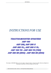
1
OPERATION MANUAL
Rev. 4.13 (20100914)
XenoWorks™
Digital
Microinjector
XenoWorks™
Digital
Microinjector
Operation Manual
(Rev. 4.13 ( (20100914))
Sutter Instrument Company
One Digital Drive
Novato, CA 94949
Voice: 415-883-0128 Web: www.sutter.com
Fax: 415-883-0572 Email: [email protected]
II
Q
Copyright © 2009 Sutter Instrument Company. All Rights Reserved.
XenoWorks is a trademark of Sutter Instrument Company.
XENOWORKS DIGITAL MICROINJECTOR OPERATION MANUAL – REV. 4.13 ( (20100914)
III
TABLE OF CONTENTS
1. GENERAL INFORMATION..............................................................................................................1
1.1 ABOUT THIS MANUAL .......................................................................................................................1
1.2 TECHNICAL SUPPORT ........................................................................................................................1
2. SAFETY WARNINGS AND PRECAUTIONS .................................................................................1
2.1 ELECTRICAL .......................................................................................................................................1
2.2 PRECAUTIONS ....................................................................................................................................2
3. PRODUCT DESCRIPTION ...............................................................................................................3
3.1 PACKING LIST ....................................................................................................................................3
3.2 INSTRUMENT DESIGN........................................................................................................................4
3.3 IDENTIFICATION OF INSTRUMENT COMPONENTS AND CONTROLS ...............................................4
3.3.1 Drierite Canister ........................................................................................................................5
3.4 CONTROLS AND FEATURES ...............................................................................................................6
3.4.1 Hold Port.....................................................................................................................................6
3.4.2 Inject/Transfer Port ...................................................................................................................6
3.4.3 Range Setting for Transfer and Compensation Pressures....................................................6
3.4.4 Hold Key......................................................................................................................................7
3.4.5 Hold Dial .....................................................................................................................................7
3.4.6 Hold Display................................................................................................................................7
3.4.7 Pulse/Continuous Injection Mode Key.....................................................................................7
3.4.8 Pressure/Pulse Width Dial ........................................................................................................8
3.4.9 Pressure/Pulse Width Display ..................................................................................................8
3.4.10 Pressure/Pulse Width Key ......................................................................................................8
3.4.11 Clear Key...................................................................................................................................8
3.4.12 Inject Key ..................................................................................................................................8
3.4.13 Transfer Dial ............................................................................................................................8
3.4.14 Transfer Display.......................................................................................................................8
4. INSTALLATION .................................................................................................................................9
5. OPERATING INSTRUCTIONS......................................................................................................11
5.1 THE HOLD FUNCTION .....................................................................................................................11
5.2 THE TRANSFER FUNCTION .............................................................................................................12
5.2.1 Transfer Channel and Settings ..............................................................................................12
5.2.3 Performance Advice .................................................................................................................13
5.3 THE INJECT FUNCTION ...................................................................................................................14
5.3.1 Setting up the High Pressure Injection Channel and Micropipette...................................14
5.3.2 Continuous Mode .....................................................................................................................14
5.3.3 Pulse Mode................................................................................................................................14
6. TROUBLESHOOTING ....................................................................................................................17
6.1 INSTRUMENT POWER ......................................................................................................................17
6.2 HOLD FUNCTION .............................................................................................................................17
6.3 TRANSFER FUNCTION .....................................................................................................................18
XENOWORKS DIGITAL MICROINJECTOR OPERATION MANUAL – REV. 4.13 ( (20100914)
IV
6.4 INJECT FUNCTION ...........................................................................................................................19
6.5 GENERAL ..........................................................................................................................................19
7. MAINTENANCE...............................................................................................................................21
7.1 REGENERATION OF THE DRIERITE DESICCANT ............................................................................21
7.2 FITTING NEW O-RINGS....................................................................................................................22
APPENDIX A. SPARE PARTS............................................................................................................23
APPENDIX B. PRESSURE CONVERSION ......................................................................................25
APPENDIX C. FUSE REPLACEMENT.............................................................................................27
REPLACEMENT FUSE RATINGS:............................................................................................................27
APPENDIX D. TRANSPORTING THE MICROINJECTOR...........................................................29
APPENDIX E. SPECIFICATIONS .....................................................................................................31
APPENDIX F. DRIERITE MATERIAL SAFETY DATA SHEET ...................................................33
APPENDIX G. LIMITED WARRANTY..............................................................................................35
APPENDIX H. DISCLAIMER .............................................................................................................37
INDEX ....................................................................................................................................................39
TABLE OF FIGURES
Figure 3-1. Components of the XenoWorks Digital Microinjector........................................................ 3
Figure 3-2. Controller/Compressor features (front view)....................................................................... 5
Figure 3-3. Controller/Compressor features (rear view). ....................................................................... 5
Figure 3-4. Remote User Interface`. ....................................................................................................... 7
Figure 4-1. Connecting the micropipette holder to the pressure tubing.............................................. 9
Figure 4-2. Attaching the pressure fitting to other end of pressure tubing.......................................10
Figure 7-1. Connecting the micropipette holder to the pressure tubing............................................22
TABLE OF TABLES
Table 2-1. Mains fuse type and ratings. .................................................................................................. 1
XENOWORKS DIGITAL MICROINJECTOR OPERATION MANUAL – REV. 4.13 ( (20100914)
V
Table 3-1. Pressure/Vacuum range settings. ........................................................................................... 6
Table 5-1. Continuous mode actions and controls. ...............................................................................14
Table 5-2. Pulse mode actions and controls...........................................................................................15
Table B-1. Pressure/Vacuum range settings. ........................................................................................25
Table C-1. Mains fuse type and ratings.................................................................................................27
XENOWORKS DIGITAL MICROINJECTOR OPERATION MANUAL – REV. 4.13 ( (20100914)
1
1. GENERAL INFORMATION
1.1 About This Manual
The XenoWorks Digital Injector is a injection system comprised of three basic parts: the
controller/compressor, injection tubing, and the user interface (remote and foot switch).
In the next, few pages you will find a product description to help you become acquainted with
the parts, followed by installation instructions, and then detailed operating instructions.
Please take the time to read these instructions to assure the safe and proper use of this
instrument.
1.2 Technical Support
Unlimited technical support is provided by Sutter Instrument Company at no charge to our
customers. Our technical support staff is available between the hours of 8:00 AM and 5:00
PM (Pacific Time) at (415) 883-0128. You may also E-mail your queries to [email protected].
XENOWORKS DIGITAL MICROINJECTOR OPERATION MANUAL – REV. 4.13 ( (20100914)
1
2. SAFETY WARNINGS AND PRECAUTIONS
Please read this manual carefully before operating the instrument.
2.1 Electrical
Use only a properly grounded power source and power cord; both appropriately rated for
use with this instrument.
Before operating the instrument, check that the instrument’s voltage rating corresponds
to the supply voltage. The voltage rating can be found on the power entry module on the
rear of the instrument.
Before making electrical connections, ensure that the instrument is switched off.
Replace fuse only with the same type and rating as indicated in the following table.
Table 2-1. Mains fuse type and ratings.
Mains
Power
Source
Mains
Voltage
Setting
110 VAC
“110”
(100 – 120
VAC)
4A, 250V
“220”
(200 – 240
VAC)
2A, 250V
220 VAC
Fuse
(Type: Time Delay, 5mm x 20mm, glass tube)
Fuse Rating
Manufacturer Examples
Bussmann: GMC-4A, GMC-4-R (RoHS), GDC-4A, or
S506-4A (RoHS)
Littelfuse: 239 004, 239.004.P (RoHS), 218.004, or
218.004.P (RoHS)
Bussmann: GDC-2A or S506-2A (RoHS)
Littelfuse: 239 002 or 239.002.P (RoHS)
A spare fuse is provided with fuse holder located in the power input module. Please refer
to “Appendix C - Fuse Replacement” for instructions on how to change the fuse.
To prevent fire or shock hazard do not expose the unit to rain or moisture.
To avoid electrical shock and exposure to hazardous electrical voltages:
•
Do not disassemble the unit. Refer servicing to qualified personnel.
•
Always use the grounded power supply cord provided to connect the unit to a
grounded outlet (3-prong). This is required to protect you from injury in the event
that an electrical hazard develops.
To comply with FDA and CE electromagnetic immunity and interference standards; and
to reduce the electromagnetic coupling between this and other equipment in your lab
always use the types and lengths of interconnect cables provided with the unit for the
interconnection of the remote user interface and foot switch.
XENOWORKS DIGITAL MICROINJECTOR OPERATION MANUAL – REV. 4.13 ( (20100914)
2
2.2 Precautions
Failure to comply with any of the following precautions may damage this device.
Please read this manual carefully before operating the instrument.
Use this instrument only for microinjection purposes in conjunction with the procedures
and guidelines in this manual.
Do not operate if there is any obvious damage to any part of the instrument.
Do not operate this instrument near flammable materials.
Do not obstruct the side vents or cooling fan intakes.
As with all microinjection devices, sharp micropipettes can fly out of their holder
unexpectedly. Always take precautions to prevent this from happening. Never loosen the
micropipette holder chuck when the tubing is pressurized, and never point micropipettes
at yourself or others. Always wear safety glasses when using sharp glass micropipettes
with pressure microinjectors.
This instrument is designed for use with capillary glass micropipettes with an outer
diameter of 1mm. For glass with outer diameters of 1.2 and 1.5 mm, please contact Sutter
Instrument to order an additional holder.
Adapters for other capillary diameters are available upon request.
Use this instrument only for microinjection purposes in conjunction with the procedures
and guidelines in this manual.
Please retain the original packaging for future transport of the instrument.
Some applications, such as piezo-impact microinjection call for the use of mercury in the
micropipette tip. The use of any hazardous materials with any XenoWorks instrument is
not recommended and undertaken at the users’ own risk.
Always transport the instrument in its original packaging, and install shipping plate
screws before shipping.
This instrument contains no user-serviceable components — do not open the instrument
casing. This instrument should be serviced and repaired only by Sutter Instrument or an
authorized Sutter Instrument servicing agent.
This device is intended only for research purposes.
Sutter Instrument reserves the right to change specifications without prior notice.
XENOWORKS DIGITAL MICROINJECTOR OPERATION MANUAL – REV. 4.13 ( (20100914)
3
3. PRODUCT DESCRIPTION
3.1 Packing List
The XenoWorks™ Digital Microinjector is shipped with the following components.
If any items are missing or damaged, contact Sutter Instrument immediately.
1.
2.
3.
4.
5.
6.
Digital Microinjector cabinet (controller/compressor)
Digital Microinjector control box (remote user interface)
Cable to connect remote user interface with controller.
Foot switch
Micropipette holder (2)
Tubing kits (2), each including 2.5 m (8 ft) clear ETFE tubing, pressure fitting, 5 spare
ferrules
7. Power cord
8. Instruction Manual
Figure 3-1. Components of the XenoWorks Digital Microinjector.
XENOWORKS DIGITAL MICROINJECTOR OPERATION MANUAL – REV. 4.13 ( (20100914)
4
3.2 Instrument Design
The XenoWorks Digital Microinjector is a pneumatic pressure control system for single-cell
microinjection and manipulation. Two independently controlled pressure channels are
available: Hold and Inject/Transfer.
The Hold Channel is designed to create negative and positive pressure sufficient to gently
hold and release a single cell, usually a mammalian oocyte, zygote or early embryo (including
fully hatched blastocyst stage embryos), against a hollow, fire-polished glass micropipette.
Ascidian, amphibian and insect embryos can be immobilized in a similar fashion, depending
upon their physical characteristics and the type of micropipette used.
The Inject/Transfer Channel provides negative and positive pressures required to aspirate
single cells (such as embryonic stem cells) into an appropriately fashioned micropipette in
preparation for transfer to another location (such as the blastocyst of an early mammalian
embryo). The transfer of cells is achieved by reversing the pressure in the transfer
micropipette and gently injecting.
There are four range settings available for the Transfer/Compensation channel, allowing for
the fine-tuning of the pressure range for a given application.
In addition to these low positive and negative pressures, the Inject/Transfer Channel is
capable of providing the high positive pressure required to inject solutions through very
narrow (typically less than one micron) injection micropipettes (during, for example, the
injection of DNA solution into the pronucleus of a mammalian “2PN” stage zygote). Users
should refer to later sections of this manual for more information on specific microinjection
applications, and to the application note “Introduction to Microinjection” available from
Sutter upon request, or for download from http://www.sutter.com.
3.3 Identification of Instrument Components and Controls
The following figures illustrate the features on the front and rear of the
controller/compressor and the controls on the remote user interface .
XENOWORKS DIGITAL MICROINJECTOR OPERATION MANUAL – REV. 4.13 ( (20100914)
5
Figure 3-2. Controller/Compressor features (front view).
Figure 3-3. Controller/Compressor features (rear view).
3.3.1 Drierite Canister
The XenoWorks Digital Microinjector incorporates an integral compressor, which takes its
air supply from the ambient air. The canister of Drierite granules dries the air before it is
compressed, to ensure a minimum of condensation and a long working life for the compressor
components. The blue Drierite granules slowly turn pink as they absorb moisture from the
input air. Once all the granules have turned pink, the Drierite should be desiccated or
replaced (described in the Maintenance chapter later in this manual). The approximate life of
the Drierite canister is one year under normal conditions.
XENOWORKS DIGITAL MICROINJECTOR OPERATION MANUAL – REV. 4.13 ( (20100914)
6
3.4 Controls and Features
3.4.1 Hold Port
This port supplies a pressure range from –350 hPa to +350 hPa (± 7 hPa) and is typically
used to control the pressure in the holding micropipette. The pressure can be varied using
the Hold Dial on the remote user interface.
3.4.2 Inject/Transfer Port
This port supplies four possible transfer/compensation ranges. Range setting 1 is the default
setting, providing from –175 hPa to +175 hPa (± 7hPa), and is typically used to control the
pressure in the transfer micropipette during embryonic stem cell transfer experiments, and
to create a compensation pressure for high-pressure injection of solutions. The compensation
pressure can be varied using the Transfer Dial on the user interface module. The pressure
pulse duration for pronuclear and adherent cell injection can be set with the Pressure Pulse
Width dial.
3.4.3 Range Setting for Transfer and Compensation Pressures
This rotary switch is used to set the compensation pressure range on the Inject/Transfer
port. The following table shows the compensation pressure range for each of the four
settings.
Table 3-1. Pressure/Vacuum range settings.
Range
Setting
Scale
Pressure
Applications
1 Unit/Transfer
Dial (approx.)
Range
psi
hPa
hPa
psi
1
Low
+2.5 to -2.5
+172 to
-172
1
0.015
2
Medium
+5 to -5
+345 to
-345
2
0.03
3
MediumHigh
+10 to -7
+689 to 483
4
0.06
4
High
+15 to -7
+1034 to 483
8
0.12
Standard setting for ES Cell,
Pronuclear Injection, and
Adherent Cell microinjection
Used when higher
compensation pressures are
needed for smaller volumes
back-loaded into injection
needle
Used for front-loading
pipette with very small
volumes (femtoliters) and to
create higher compensation
pressures for these small
volumes.
XENOWORKS DIGITAL MICROINJECTOR OPERATION MANUAL – REV. 4.13 ( (20100914)
7
Figure 3-4. Remote User Interface`.
3.4.4 Hold Key
This key is used to toggle the Hold pressure on and off. In the OFF position, no pressure is
applied to the Hold Port. In the ON position, the pressure, in hPa, shown in the Hold LED
Display (above the Hold Dial) is applied to the Hold Port.
3.4.5 Hold Dial
Controls the pressure delivered to the Hold Port when the Hold Key is in the ON position.
The range is, continuous from –350 hPa to +350 hPa (± 7 hPa).
3.4.6 Hold Display
Displays the pressure delivered to the Hold Channel (in hPa).
3.4.7 Pulse/Continuous Injection Mode Key
This key toggles between the pulse mode and continuous mode used for high-pressure
injections. The pulse pressure and duration are set with the Pressure/Pulse Width Dial. The
continuous pressure is active as long as the Inject Key or footswitch is held down. The mode
selected and active is indicated with a green LED.
XENOWORKS DIGITAL MICROINJECTOR OPERATION MANUAL – REV. 4.13 ( (20100914)
8
3.4.8 Pressure/Pulse Width Dial
This dial is used to adjust the pressure and duration of injection. Injection pressure can be
adjusted from 0 to 5600 (± 50 hPa) in 70 hPa increments. Pulse duration can be adjusted
from 0.01 to 10 seconds in 0.01-second increments.
3.4.9 Pressure/Pulse Width Display
This display indicates either the injection pressure (in hPa) or the injection duration (in
seconds) when in Pulse Mode. Toggling between these two values is accomplished with the
Pressure/Pulse Width Key.
3.4.10 Pressure/Pulse Width Key
This key is used to toggle the Pressure/Pulse Width Dial/Display between “Pressure” and
“Pulse Width”.
3.4.11 Clear Key
Applies maximum pressure to the right hand (Inject/Transfer) channel and is used to clear
blockages of the micropipette. When the key is pressed and held down, the pressure applied
increases from zero to maximum pressure (80 psi).
CAUTION: THE CLEARING FUNCTION SHOULD NOT BE USED WITH
MICROPIPETTES THAT HAVE TIP INNER DIAMETERS GREATER THAN
APPROXIMATELY ONE (1) MICRON.
3.4.12 Inject Key
This key applies the pressure (set by the center Pressure/Pulse Width Dial) to the
Inject/Transfer pressure port. When the instrument is in Pulse Mode, the duration of the
pressure will be for the time set by the Pulse Width Dial. When the instrument is in
Continuous Mode, the pressure is applied for as long as the Inject Key (or footswitch) is held
down.
3.4.13 Transfer Dial
This dial controls the pressure continuously supplied to the Inject/Transfer Port. Range
Setting 1 (standard setting) provides –175 hPa to +175 hPa (± 7 hPa) of pressure.
3.4.14 Transfer Display
This display indicates the low pressure being constantly delivered to the Transfer Channel
(in hPa).
XENOWORKS DIGITAL MICROINJECTOR OPERATION MANUAL – REV. 4.13 ( (20100914)
9
4. INSTALLATION
NOTE: These instructions refer to the use of the XenoWorks Digital Microinjector with the
XenoWorks Micromanipulator. While the Digital Microinjector is supplied with micropipette
holders that are compatible with a number of different micromanipulators, the setup
procedure used with those micromanipulators may vary slightly.
1. Unpack the XenoWorks Digital Microinjector.
2. Remove the (4) shipping screws and plate from the right side of the instrument. (Retain
plate & screws for possible future transport.)
3. Connect the microinjector compressor and user interface modules using the cable
provided.
4. Place the compressor module on a flat, solid surface, away from the microscope (on a
different surface from microscope’s is strongly suggested).
5. Ensure that the compressor is located close enough to the microscope that the pressure
lines will reach without placing any strain on the micropipette holders or
micromanipulators. The user interface module can be located conveniently next to the
microscope.
6. Remove the micropipette holders from their cases and connect them to the free end of the
pressure tubing as shown below.
Figure 4-1. Connecting the micropipette holder to the pressure tubing.
XENOWORKS DIGITAL MICROINJECTOR OPERATION MANUAL – REV. 4.13 ( (20100914)
10
9. Attach a pressure fitting to the other end of the pressure tubing as shown in below. Do
not use tools to tighten pressure fittings since damage may result.
Figure 4-2. Attaching the pressure fitting to other end of pressure tubing.
10. Connect each of the pressure lines to the appropriate ports of the compressor module.
You will hear a “click” sound as the fittings engage in the port.
11. Connect the power cord to the power input module on the rear of the compressor and a
mains power outlet.
The XenoWorks Digital Microinjector is now set up and ready for use.
XENOWORKS DIGITAL MICROINJECTOR OPERATION MANUAL – REV. 4.13 ( (20100914)
11
5. OPERATING INSTRUCTIONS
5.1 The Hold Function
If injecting adherent cells, or if no Hold Function is required, skip this section and move on
to the Transfer Function. The left hand rotary control and its associated LED display
correspond to the pressure control of the left-hand port on the front of the compressor
module, and of any tubing, micropipette holder and micropipette attached to that port. The
pressure delivered by this port ranges from -350 hPa to 350 hPa (± 7hPa), and is designed to
allow a typical holding micropipette to hold a mammalian oocyte, blastocyst or zygote, for
example. The Hold Function can be used in a similar fashion to that of a traditional
micrometer-type air microinjector, by “dialing” the pressure up or down to release or hold
the cell in place. A setting of +20 – 30 will advance the meniscus to the top and reducing the
pressure to +10 will being to draw in the cell or egg.
Setting up the holding channel and micropipette:
1. First, ensure that the Hold Function is switched off (the default position of the Hold
Function after first powering up the unit), then check that the tubing and fitting are
properly engaged in the Hold Channel port, (the left hand port on the front of the
compressor module) and that all fittings are finger-tight.
2. Fit the holding micropipette into the micropipette holder by loosening the clear plastic
chuck ¼ turn, gently inserting the micropipette, and tightening the chuck until the
micropipette cannot be moved in or out of the holder.
CAUTION: Do not over tighten the chuck; doing so could crush the O-rings and prevent
them from making a airtight seal around the base of the micropipette. Take care not to
force the micropipette into a holder. If the micropipette will not easily slide in, it is
because either the chuck is locked down, or there is an obstruction such as broken glass
in the holder. Care should be taken to ensure the back end of the micropipette is clean
and free of cracks or breakages to avoid damage to the O-rings. Despite these
precautions, the O-rings will eventually wear, and they should be inspected from time to
time and replaced when necessary.
3. Once the micropipette is fitted into the holder, the holder can be locked into the
micropipette holder clamp on the micromanipulator drive module and the tip of the
micropipette lowered into the injection chamber. Caution: Take care not to let the holder
“snap” into the spring-loaded clamp, since this may cause damage to the micropipette tip.
Turn the Hold Port on and dial the hold pressure up to +20 – 30. This will prevent oil or
media from drawing into the pipette.
4. When the micropipette is lowered into the medium, a small quantity of medium will be
aspirated by capillary action into the tip. It is unnecessary to aspirate any more medium
than this.
5. With the Hold Pressure Dial set at approximately zero, switch the Hold Function on. The
holding channel is now ready to use.
XENOWORKS DIGITAL MICROINJECTOR OPERATION MANUAL – REV. 4.13 ( (20100914)
12
6. Under certain conditions (such as a broken micropipette), it can become possible to
aspirate fluid from the injection chamber, through the tubing and into the compressor
module through the front port. Particular care should be taken not to allow this to occur.
To safeguard against this event, a fluid sensor has been installed inside the controller. If
fluid is drawn into the controller, the fluid sensor will be activated and a compensating
positive pressure will turn onto expel the fluid. The positive pressure will stay on
continuously even if you power off and on the injector.
To avoid getting aspirating fluid into the controller:
a. Making sure that the micropipettes are removed from the injection chamber when it
is left unattended, by, for example, using the micromanipulator’s Home Function.
b. Switch off the Hold Pressure Port and turn the Transfer pressure to zero when the
device is to be left unattended.
If fluid has been inadvertently aspirated into the Hold Port tubing, it can be purged by
connecting the Hold Port to the Inject/Transfer Port. Then pressing the ‘Clear’ key. Fluid
in the Hold Port tubing can also be purged by turning the Hold Dial to maximum positive
pressure until the fluid is drained. Never leave the unit unattended when there is fluid in
the tubing. If this happens, contact Sutter Instrument for tech support and instructions
on how to resolve this matter.
5.2 The Transfer Function
The Transfer Function works in a similar manner to the Hold Function, but is always active
– there is no on/off control. Pressure ranges from -175 hPa to 175 hPa (± 7 hPa) (Range 1),
and is applied to the pressure port used to control the pressure in the transfer/inject
micropipette. A typical application for which this function might be used includes the
transfer of embryonic stem cells into a blastocyst.
Caution: Do not shut down and restart the device with a micropipette immersed in the dish,
since during the device’s initialization process, a small amount of pressure is sometimes
released.
5.2.1 Transfer Channel and Settings
1. As with the holding channel, all fittings should be tight and fully engaged, and the
transfer micropipette inserted into the holder with care. Remember not to tighten the
chuck too far or the O-rings will be crushed.
2. Insert the micropipette holder into the clamp on the micromanipulator. Take care not to
let the holder “snap” into the spring-loaded clamp, since damage may occur to the
micropipette tip.
3. Adjust the micropipette holder, by sliding it up or down the clamp, so that the tip of the
micropipette projects into the optical axis of the microscope. For details on aligning
micropipettes, please refer to the instruction manual of the micromanipulator. If using a
micropipette with a bend, rotate the holder in the clamp until the bend section is parallel
to the bottom of the injecting chamber.
4. Turn the Transfer Pressure Dial +80 and lower the micropipette into the injection
medium.
XENOWORKS DIGITAL MICROINJECTOR OPERATION MANUAL – REV. 4.13 ( (20100914)
13
5. A small amount of medium will be drawn into the micropipette by capillary action. Wait
approximately 30 seconds for the pressure to equalize, and then slowly turn the Transfer
Dial clockwise until the meniscus between air and medium is less than approximately 2
mm from the micropipette tip. The Transfer Dial should read between +060 to +090 at
this point.
6. The micropipette can now be loaded with, for example, embryonic stem cells by placing
the tip close to the material to be aspirated and slowly turning the Transfer Dial counterclockwise to lower settings (e.g., between +30 - +70).
7. Expelling cells from the micropipette is achieved by gently turning the dial clockwise, in
much the same way as with a standard micrometer microinjector.
5.2.3 Performance Advice
The XenoWorks Digital Microinjector uses precision-regulated air pressure to hold, inject and
manipulate cells and other tissue samples. The best control is attained when the interface
(meniscus) between the air in the micropipette and the medium in the dish is as close as
possible to the tip of the micropipette. The optimum position of the meniscus will depend
upon a number of factors including the type, size and diameter of the micropipette, the
viscosity of the medium and the depth of the injecting chamber. In general, though, the
closer to the micropipette tip the meniscus can be brought, the better the control over the
pressure. During the course of an experiment, it may be necessary to ensure that the
meniscus has not been allowed to be pulled too far up inside the micropipette. If the
meniscus is too close to the micropipette tip, control can become too sensitive, and will not be
smooth. This is particularly so with embryonic stem cell transfer micropipettes. If this is the
case, simply draw a little more medium into the micropipette by turning the Transfer Dial
counter-clockwise.
CAUTION: Care should be taken not to apply too much positive pressure to the
micropipette; as with any other microinjection device, it is possible to purge all the medium
from the micropipette and stream bubbles into the injection chamber, which may damage
tissues and obscure the microscope optics.
NOTE: The pressure reading on the LED display is a guide only; it is possible to maintain
embryonic stem cells stationary in the transfer micropipette tip, yet still show a positive
pressure in the display. The display is showing only the pressure supplied to the
micropipette, even though the pressure effects observed at the micropipette tip are a
combination of pressure supplied by the injector and capillary forces.
CAUTION: Under certain conditions (such as a broken micropipette), it can become possible
to aspirate fluid from the injection chamber, through the tubing and into the compressor
module through the front port. Particular care should be taken not to allow this to happen,
since the compressor module could be damaged. Safeguard against such damage by:
1. Making sure that the micropipettes are removed from the injection chamber when it is
left unattended (by using the micromanipulator’s Home Function, for example).
2. Switch off the Hold Pressure Port and turn the Transfer pressure to zero when the device
is to be left unattended.
XENOWORKS DIGITAL MICROINJECTOR OPERATION MANUAL – REV. 4.13 ( (20100914)
14
Fluid that has been inadvertently aspirated into the Inject/Transfer tubing can be purged by
pressing the Clear Key (ensure there is no micropipette in the holder before doing this).
Never leave the unit unattended when there is fluid in the tubing.
5.3 The Inject Function
5.3.1 Setting up the High Pressure Injection Channel and Micropipette
If the digital microinjector is being used for the high pressure injection of solutions (such as
DNA, RNA, proteins etc.) into cells through narrow microinjection micropipettes (tip sizes
less than 1 micron), the Transfer Function should be used as an adjustable positive pressure
(“base” pressure) applied to the tip of the injection micropipette. This ensures that there is a
gentle, constant flow of solution from the micropipette, preventing dilution of the solution to
be injected by the medium in the injection chamber. The base pressure also minimizes, to
some degree, blockage of the micropipette tip by foreign objects in the surrounding medium.
The wider the tip of the injection micropipette, the less base pressure is required. As a rule,
start at 5 hPa and increase slowly until a gentle stream of material can be seen coming from
the tip. Under certain microscope optics, this stream is easily visible as a “Schlieren” pattern
resulting from the different densities of injected solution and surrounding medium. Once the
stream can be seen issuing from the micropipette tip, reduce the base pressure until the
stream almost disappears. Two modes of high-pressure injection are available to suit
different users’ preferences:
5.3.2 Continuous Mode
High pressure of a predetermined value is applied for as long as the Inject Key or the
footswitch is held down. This mode is useful when injecting a field of cultured adherent cells,
where long durations and/or high pressures will rupture and kill the cells. The pressure can
be set low, and the duration short to deliver tiny, discrete and reproducible volumes to each
cell.
Table 5-1. Continuous mode actions and controls.
Action
Adjust compensation pressure
Select continuous injection
mode
Select high-pressure
adjustment
Adjust high-pressure value
Inject
Control Used
Transfer dial
Pulse/Cont. key to "Cont."
Pressure/Pulse Width key to
"Pressure
Pressure/Pulse Width dial
Inject key or footswitch
5.3.3 Pulse Mode
Pulse Mode provides high-pressure injection by discrete pulses of a given pressure (in hPa)
for a predetermined amount of time. Pressure is applied for a predetermined duration no
matter how long the Inject Key or footswitch is pressed. This mode is useful for the injection
of DNA into the pronucleus of a mammalian zygote for example, where successful injection
XENOWORKS DIGITAL MICROINJECTOR OPERATION MANUAL – REV. 4.13 ( (20100914)
15
requires a high pressure and a slight inflating (approximate doubling in size) of the
pronucleus can be seen.
Table 5-2. Pulse mode actions and controls.
Action
Adjust compensation pressure
Select pulse injection mode
Select high-pressure
adjustment
Adjust high-pressure value
Select injection duration
adjustment
Adjust injection duration
Inject
Control Used
Transfer dial
Pulse/Cont. key to "Pulse"
Pressure/Pulse Width key to
"Pressure"
Pressure/Pulse Width dial
Pressure/Pulse Width key to
"Pulse Width"
Pressure/Pulse Width dial
Inject key or footswitch
Once the base pressure, injection pressure and, if used, injection duration have been set, the
system is ready to begin injection. Consult the application note “Introduction to
Microinjection” for more information on microinjection techniques.
XENOWORKS DIGITAL MICROINJECTOR OPERATION MANUAL – REV. 4.13 ( (20100914)
17
6. TROUBLESHOOTING
6.1 Instrument Power
Problem
Cause
Solution
The instrument
does not activate
when the power is
switched on.
1. The power cord is not connected
to an appropriate supply.
Connect the power cord to the mains
supply. Be sure that the power rating is
matched to the requirements of the
instrument. Catalog number BRE110
requires 100-110v AC, BRE220 requires
220-240v AC.
Replace the fuse and check that the power
supply is appropriate to the requirements
of the device.
Connect the user interface module to the
compressor module using the cable
provided.
2. The protection fuse has blown.
3. The user interface module is not
properly connected.
6.2 Hold Function
Problem
Cause
Solution
The holding
pressure is
insufficient to hold
a cell, or the “hold”
control seems
unresponsive.
1. The holding pressure is not
activated.
2. The tubing is not connected to
the holding pressure port.
Activate the holding pressure with the
Hold on/off switch (green LED will light).
Connect the tubing to the left hand
(holding) port. There will be a positive
click when the fitting is engaged.
Check the tubing for kinks, holes and
other damage and replace if necessary
(order part # BR-DT). Tighten all
fittings. Replace ferrules.
Slowly rotate the Hold control clockwise,
until the air/medium meniscus is as close
to the tip as possible. Note that it is
possible to create an effective holding
pressure and still show a positive value in
the Hold LED display.
Carefully tighten the pipette holder’s
plastic tip.
Carefully tighten the rod holder’s black
parts located behind the plastic tip.
3. There is a leak in the tubing, or
the pressure fittings are loose.
4. The air/medium interface is too
far inside the micropipette tip.
5. The plastic tip of the pipette
holder is not tightened down.
6. The black parts on the rod
holder behind the plastic tip are
loose.
XENOWORKS DIGITAL MICROINJECTOR OPERATION MANUAL – REV. 4.13 ( (20100914)
18
6.3 Transfer Function
Problem
Cause
Solution
The Transfer
pressure control
seems
unresponsive.
1. The tubing is not connected to
the transfer pressure port.
Connect the tubing to the right hand
(inject/transfer) port. There will be a
positive click when the fitting is engaged.
Check the tubing for kinks, holes and
other damage and replace if necessary
(order part # BR-DT). Tighten all fittings.
Replace ferrules.
Slowly rotate the Transfer control
clockwise, until the air/medium meniscus
is as close to the tip as possible.
Carefully tighten the pipette holder’s
plastic tip.
Carefully tighten the rod holder’s black
parts located behind the plastic tip.
2. There is a leak in the tubing, or
the fittings are loose.
3. The air/medium interface is too
far inside the micropipette tip.
4. The plastic tip of the pipette
holder is not tightened down.
5. The black parts on the rod
holder behind the plastic tip are
loose.
Note that the Transfer LED display is a guide only and that it is possible to have a fully equalized
micropipette (no net in- or out-flow of material), and still show a positive or a negative (i.e., non-zero)
value in the display. If, after performing the above checks, the device is still unresponsive, please
contact your Sutter Instrument distributor for assistance.
The Transfer
display shows a
positive or negative
pressure, yet the
cells are stationary
inside micropipette.
1. Factors such as viscosity of
medium and capillary/surface
tension forces create a negative
pressure in the micropipette. It
may take slight POSITIVE
pressure from the microinjector
to balance this action and even
with a net negative pressure at
the tip, the pressure applied to
the tool may be slightly positive.
If the Transfer pressure can be
dialed up or down with no effect
on the aspirated cells, there may
be a problem with the pressure
hose connection (see “The
Transfer pressure control seems
unresponsive”, above).
2. Tubing connector not plugged
in all the way into the port on the
front panel of the digital injector.
3. Plastic tip of the pipette holder
is not tightened down.
This is normal. Use the display pressure
value as a guide only.
Make sure that the tubing connector is
plugged in all the way into the port.
Carefully tighten the pipette holder’s
plastic tip.
XENOWORKS DIGITAL MICROINJECTOR OPERATION MANUAL – REV. 4.13 ( (20100914)
19
6.4 Inject Function
Problem
Cause
Solution
There is no
material flowing
from the tip of the
micropipette, even
when positive
pressure is applied
(80 psi; 5566 hPa
on display).
1. The microscope optics are
unable to resolve the stream
Switch to suitable optics, if available.
Brightfield illumination will be unlikely to
resolve the stream, unless the injected
solution is colored. Phase contrast will be
more effective and Nomarski and
Hofmann better still. A constant stream
can also be detected by moving the
micropipette tip close to a freely floating
cell and trying to “blow it away”.
Press the Clear Key a number of times,
holding the key down longer each time
until the blockage is cleared. If this does
not clear the blockage, the pipette should
be replaced.
2. The micropipette is blocked.
CAUTION: Some residual pressure may remain in the tubing. Take great care to point the
micropipette in a safe direction when removing it from the holder.
6.5 General
Problem
Cause
Solution
Compressor motor
runs continuously
for more than five
minutes when the
instrument is on,
but not being used.
1. There is a leak in one of the
pressure lines.
Check each pressure line for kinks or
holes. Replace lines if necessary - order
part # BR-DT.
Push the pressure fitting into its port until
a click is felt. If no tubing is fitted to a
port, check that the port is closed by
pressing the release tab on top of the port.
All pressure fittings should be finger tight
- no tools are necessary to tighten pressure
fittings.
Insert a micropipette into the holder. If no
micropipettes are being used, switch the
Hold pressure off and turn the Transfer
pressure down to zero.
2. The pressure fitting has not
been fully engaged in the
pressure port on the front of the
compressor module.
3. There is a loose pressure
fitting.
4. There is no micropipette in the
holder.
If, after performing the above checks, the compressor motor continues to run for longer than five
minutes, shut the instrument down and contact your Sutter distributor.
The compressor is
loud when
activated.
The shipping plate and screws on
the right side panel have not been
removed.
Turn off the compressor. Place the cabinet
on its left side (front side up) and remove
the hex-head screws and shipping plate.
XENOWORKS DIGITAL MICROINJECTOR OPERATION MANUAL – REV. 4.13 ( (20100914)
20
Problem
Cause
Solution
NOTE: To replace the shipping plate before storage or shipping, place the cabinet on its side again so
that the receiving holes inside on the compressor line up with the external holes.
“ERR” appears on
all B displays of the
remote user
interface.
1. There is an electronic short on
the circuit board.
2. There is a constant/continuous
positive pressure and the
compressor is always on.
It is possible that the solution is
down all the way all the way into
the tubing and into the
compressor.
If this has happened, the fluid
sensor has been
activated/triggered inside the
injector to create continuous
positive pressure with protectant
fluid used to protect the
compressor from water damage.
Contact Sutter Instrument.
Contact Sutter Instrument.
XENOWORKS DIGITAL MICROINJECTOR OPERATION MANUAL – REV. 4.13 ( (20100914)
21
7. MAINTENANCE
7.1 Regeneration of the Drierite Desiccant
The XenoWorks™ Digital Microinjector needs no routine maintenance except for periodic
replacement or “regeneration” of the Drierite desiccant. The indicating Drierite, found in the
canister on the rear of the microinjector, is a desiccant made of calcium sulfate (97%) and
cobalt chloride (3%). Drierite is non-toxic and can be handled with few precautions. This
material is used to remove water vapor from the air intake of the system. As it absorbs more
moisture, it becomes pink in color and must eventually be “regenerated” (dried) or replaced
with new indicating desiccant canister. New canisters are available from Sutter (order part
number X870700), or the existing granules can be regenerated by following these
instructions.
1. Turn off the device and unplug the power cord. To remove the canister from the device,
pull off the output (left) air tube from the white plastic connector on the canister.
2. The two black plastic hold-downs that secure the canister to the rear panel can be
released by forcing one half of the connector out of the other half at the point where they
meet. Remove the canister and unscrew the plastic end cap, being careful not to lose the
black rubber-sealing ring that forms the airtight seal within the cap.
3. With the cap off, remove the spring, the perforated aluminum plate and the first filter
and second filter. The far aluminum plate can be kept in place. Pour the Drierite out onto
a glass or metal tray, spreading it evenly, one granule deep, and heat it for one hour at
200°C. Pre-dry both filters at 100°C for 30 minutes just prior to assembly.
4. Before refilling the canister, the Drierite granules should be cooled in an airtight
container. After cooling, replace the Drierite granules, keeper, and filters into the
canister in the order they were removed.
5. First, install the filter against the keeper that was left in the canister.
6. If this keeper was removed, slide it in first ensuring that it lays flat against the plastic
shoulders at the far end of the canister. With the far keeper and filter in place, pour in
the new or regenerated Drierite.
7. Next, insert the second filter followed by the keeper and the spring.
8. Check that the rubber seal is in the proper position and, if you wish, apply a thin layer of
vacuum grease on to the rubber seal to ensure a tight fit. There is no need to over-tighten
the cap, but a good seal is needed to prevent air leaks.
9. Reinstall the canister on the injector, with the air tube connections to the top.
10. Slide the black plastic hold-downs inside one another and squeeze them together to
firmly hold the canister in place.
11. At this point, re-connect the air-output tube (the one which enters into the rear panel of
the injector).
CAUTION: Failure to maintain the Drierite may result in impaired instrument performance
and can damage the instrument.
XENOWORKS DIGITAL MICROINJECTOR OPERATION MANUAL – REV. 4.13 ( (20100914)
22
7.2 Fitting New O-rings
Routine use will create wear on the three black O-rings located in the tip of the micropipette
holder chuck. Occasionally, the O-rings will need to be replaced. To do this, gently remove
the old O-rings with an appropriate tool (a bent paper clip, for example). Discard the old Orings and insert three new ones, taking care to ensure that they are flat against the back of
the chuck. The new O-rings can be pushed down inside the chuck by gently screwing the
chuck onto the knurled black aluminum pressure fitting. Take care not to damage the chuck
during this procedure.
Figure 7-1. Connecting the micropipette holder to the pressure tubing.
XENOWORKS DIGITAL MICROINJECTOR OPERATION MANUAL – REV. 4.13 ( (20100914)
23
APPENDIX A. SPARE PARTS
BR-MH
Micropipette holder, includes micropipette holder body, 9 O-rings
BR-DT
Digital tubing kit, includes 2 x 2 m ETFE tubing, pressure fitting, 6 ferrules
X870700
Drierite canister
XENOWORKS DIGITAL MICROINJECTOR OPERATION MANUAL – REV. 4.13 ( (20100914)
25
APPENDIX B. PRESSURE CONVERSION
XenoWorks Digital Microinjector displays pressure in hecta-Pascals (hPa). The following
conversion factors should be used for other pressure units:
1 hPa = 100 Pascals (Pa)
1 Pascal = 0.01 hPa
1 hPa = 1 millibars
1 millibar = 1 hPa
1 hPa = .001 bars
1 bar = 1000 hPa
1 hPa = 0.0145 psi
1 psi = 68.9655 hPa
Table B-1. Pressure/Vacuum range settings.
Range
Setting
Scale
Pressure
Applications
1 Unit/Transfer
Dial (approx.)
Range
psi
hPa
hPa
psi
1
Low
+2.5 to -2.5
+172 to
-172
1
0.015
2
Medium
+5 to -5
+345 to
-345
2
0.03
3
MediumHigh
+10 to -7
+689 to 483
4
0.06
4
High
+15 to -7
+1034 to 483
8
0.12
Standard setting for ICSI,
NT, ES Cell, Pronuclear
Injection, and Adherent Cell
microinjection
Used when higher
compensation pressures are
needed for smaller volumes
back-loaded into injection
needle
Used for font-loading pipette
with very small volumes
(femtoliters) and to create
higher compensation
pressures for these small
volumes.
XENOWORKS DIGITAL MICROINJECTOR OPERATION MANUAL – REV. 4.13 ( (20100914)
27
APPENDIX C. FUSE REPLACEMENT
In the event that the instrument fails to power up when it is switched on, the line power
fuses should be checked to determine whether they have blown. The fuses are located in the
fuse holder in the power entry module on the rear of the control module.
To replace a fuse, first unplug the power cord from the power entry module, revealing the
fuse holder below. Remove the fuse holder. Note that both fuses in the fuse holder are used
simultaneously. Either one or both may have blown. Discard the blown fuse(s). Insert
appropriately rated replacement fuses (see below). Replace the fuse holder in the power entry
module and reconnect the power cord.
Replacement Fuse Ratings:
Table C-1. Mains fuse type and ratings.
Mains
Power
Source
Mains
Voltage
Setting
110 VAC
“110”
(100 – 120
VAC)
4A, 250V
“220”
(200 – 240
VAC)
2A, 250V
220 VAC
Fuse
(Type: Time Delay, 5mm x 20mm, glass tube)
Fuse Rating
Manufacturer Examples
Bussmann: GMC-4A, GMC-4-R (RoHS), GDC-4A, or
S506-4A (RoHS)
Littelfuse: 239 004, 239.004.P (RoHS), 218.004, or
218.004.P (RoHS)
Bussmann: GDC-2A or S506-2A (RoHS)
Littelfuse: 239 002 or 239.002.P (RoHS)
XENOWORKS DIGITAL MICROINJECTOR OPERATION MANUAL – REV. 4.13 ( (20100914)
29
APPENDIX D. TRANSPORTING THE MICROINJECTOR
When transporting, use the original packaging and the supplied shipping screws and
shipping plate. If the packaging and shipping screws have been misplaced, contact your local
Sutter distributor.
Install the four shipping screws and the shipping plate to the right side of the compressor
module using the following procedure:
1. Align shipping plate holes with holes in the right side of the instrument.
2. Mount the shipping plate using the four 10-32 socket-head shipping screws provided by
placing screws first through plate, then through instrument side panel and finally
engaging screws into interval motor bracket.
3. Slowly advance the shipping screws in evenly to secure the compressor before storage or
shipping.
4. Tighten the (4) shipping screws using a 5/32" allen wrench.
5. The controller/compressor is now ready for transport, and can be placed into the original
foam packaging for shipping.
CAUTION: Do not transport the compressor module without using the provided shipping
screws and plate or instrument damage may result. If screws and plate are misplaced and
unavailable, please contact Sutter Instrument to obtain the proper hardware.
XENOWORKS DIGITAL MICROINJECTOR OPERATION MANUAL – REV. 4.13 ( (20100914)
31
APPENDIX E. SPECIFICATIONS
Q
Pressure channels
2, independently controllable
Maximum pressure
5600 hPa (+/- 50 hPa)
High pressure
0 to 5600 hPa (+/- 50 hPa)
in 7 hPa increments
Injection time
0.01 to 10 seconds
in 0.01 sec increments
Inject activation
Transient; hand or foot switch
Transfer pressure
-175 to +175 hPa (+/- 7 hPa)
in 7 hPa increments
Hold pressure
-350 to +350 hPa (+/- 7 hPa)
in 7 hPa increments
Clear function
Ramp from Inject value to
maximum pressure
Display
3 x 7-segment LED
Controls
Tactile keys, rotary optical
encoders
Tubing
2 m ETFE
Micropipette holder diameter
4 mm
Micropipette compatibility
1 mm capillary glass* other sizes
available upon request
Piezo-impact drive compatibility
Prime Tech, Burleigh
Storage Environment
Temperature:
Humidity:
0 – 70°C (32 – 158°F)
0 – 95% (non-condensing)
Operating Environment
Temperature:
Humidity:
3.5 – 35°C (38.3 – 95°F)
0 – 80% (non-condensing)
(80% @ 31°C (87.8°F), decreasing
linearly to 67% @ 35°C (95°F))
Regulatory
Safety:
EMC:
EN61010-1, TUV, CE
EN61326, TUV, CE
XENOWORKS DIGITAL MICROINJECTOR OPERATION MANUAL – REV. 4.13 ( (20100914)
32
Cleaning
70% alcohol (or e.g. UV)
Dimensions (H x W x D)
Compressor module - 407 x 440 x
150 mm (16 x 17 x 6 inches)
User interface module - 164 x 123 x
70 mm (6.5 x 4.8 x 2.8 inches)
Weight
Controller/compressor:
Remote user interface:
Electrical:
Mains voltage
Power consumption
Power cord
Mains fuse (rear of cabinet)
Input power (BRE110)
Input power (BRE220)
1504 g (3.36 lb (3 lb, 5 oz))
42 g (0.093 lb (1.48 oz))
100 - 240 V, 50/60 H
440W
10A, 250V, with safety ground plug
Time delay (or time lag) 5 x 20 mm
glass tube.
100–120 VAC (±10%), 50/60 Hz
Fuse rating: 4.0 A. Power: 450 VA
220–240 VAC (± 10%), 50/60 Hz
Fuse rating: 2.0 A. Power: 280 VA
For manufacturer examples, refer
to Table C-1 Mains fuse type and
ratings.
XENOWORKS DIGITAL MICROINJECTOR OPERATION MANUAL – REV. 4.13 ( (20100914)
33
APPENDIX F. DRIERITE MATERIAL SAFETY DATA SHEET
IDENTITY: INDICATING DRIERITE
DESCRIPTION: 1/16" TO 1/4" BLUE GRANULES
DATE PREPARED 1-3-96
SECTION I
MANUFACTURER’S NAME:
ADDRESS:
EMERGENCY PHONE NUMBER:
INFORMATION PHONE NUMBER:
W.A. HAMMOND DRIERITE CO. LTD.
P.0. BOX 460,
138 DAYTON AVE.,
XENIA, OH 45385
(513) 376-2927
(513) 376-2927
SECTION II
INGREDIENTS
CHEMICAL IDENTITY
%
OSHA PEL
ACGIH TLV
UNITS
C.A.S. #
7778-18-9
CALCIUM SULFATE
97
15
10
mg/M3
COBALT CHLORIDE
3
0.05*
0.05*
mg/M3
7646-79-9
*(AS COBALT METAL)
HAZARDOUS MATERIALS IDENTIFICATION SYSTEM (HMIS)
HEALTH
FLAMMABILITY
REACTIVITY
PROTECTIVE EQUIPMENT
1
0
1
E
SECTION III
PHYSICAL/CHEMICAL CHARACTERISTICS
SPECIFIC GRAVITY:(H20=1):
SOLUBILITY IN WATER:
MELTING POINT:
APPEARANCE:
1.87
0.25 GRAMS PER LITER
1450° C DECOMPOSES
BLUE GRANULES; NO ODOR
SECTION IV
FIRE AND EXPLOSION HAZARD DATA
FLASH POINT:
EXTINGUISHING MEDIA:
SPECIAL FIREFIGHTING PROCEDURES:
UNUSUAL FIRE AND EXPLOSION HAZARDS:
NONE
NOT COMBUSTIBLE
NONE
NONE
SECTION V
REACTIVITY DATA
STABILITY:
INCOMPATIBILITY (MATERIALS TO AVOID):
HAZARDOUS DECOMPOSITION BYPRODUCTS:
HAZARDOUS POLYMERIZATION:
STABLE
STRONG ACIDS
Cl2 @ 318°C; SO3 @ 1450°C
WILL NOT OCCUR
SECTION VI
HEALTH HAZARD DATA
EYES: PARTICLES MAY CAUSE IRRITATION.
SKIN: THIS MATERIAL IS NOT TOXIC. MAY DRY OR IRRITATE SKIN
INHALATION: MAY CAUSE AN IRRITATION OF RESPIRATORY ORGANS OF SENSITIVE PERSONS
RESULTING IN THE OBSTRUCTION OF AIRWAYS WITH SHORTNESS OF BREATH.
INGESTION: MAY CAUSE VOMITING, DIARRHEA AND SENSATION OF WARMTH
SIGNS AND SYMPTOMS OF OVER EXPOSURE: EYE, NOSE, THROAT, OR RESPIRATORY IRRITATION
XENOWORKS DIGITAL MICROINJECTOR OPERATION MANUAL – REV. 4.13 ( (20100914)
34
CARCINOGENICITY OF INGREDIENTS:
MATERIAL
IARC
NTP
OSHA
CALCIUM SULFATE
NOT LISTED
NOT LISTED
NOT LISTED
COBALT CHLORIDE
YES*
NO
NO
*(COBALT & COBALT COMPOUNDS ARE CLASSIFIED AS GROUP 2B)
MEDICAL CONDITIONS GENERALLY AGGRAVATED BY EXPOSURE:
PRE-EXISTING UPPER RESPIRATORY AND LUNG DISEASE SUCH AS, BUT NOT LIMITED TO,
BRONCHITIS, EMPHYSEMA & ASTHMA
EMERGENCY AND FIRST AID PROCEDURES:
EYES: FLUSH WITH WATER
DUST INHALATION:
REMOVE TO FRESH AIR
SKIN: WASH WITH WATER
INGESTION:
NONE KNOWN
SECTION VII
SPILL OR LEAK PROCEDURES
STEPS TO BE TAKEN IN CASE MATERIAL IS RELEASED OR SPILLED:
SWEEP OR VACUUM MATERIAL INTO APPROPRIATE WASTE CONTAINER FOR DISPOSAL. AVOID
DUSTING CONDITIONS.
WASTE DISPOSAL METHOD: THIS MATERIAL CAN BE DISPOSED OF AS AN INERT
SOLID WASTE IN AN APPROVED LAND FILL OR BY OTHER PROCEDURES ACCEPTABLE UNDER FEDERAL,
STATE AND LOCAL REGULATIONS.
PRECAUTIONS TO BE TAKEN IN HANDLING AND ST0RING:
KEEP CONTAINER CLOSED
STORE IN A COOL DRY PLACE
AVOID GENERATING DUST
SECTION VIII
CONTROL MEASURES
RESPIRATORY PROTECTION: NIOSH/OSHA APPROVED FOR DUST
VENTILATION: TO MEET TLV REQUIREMENTS
EYES: SAFETY GLASSES OR GOGGLES
OTHER PROTECTIVE EQUIPMENT: GLOVES OR PROTECTIVE CLOTHING ARE NOT USUALLY NECESSARY BUT
MAY BE DESIRABLE IN SPECIFIC WORK SITUATIONS.
SECTION IX
• REFERENCES
U.S. DEPARTMENT OF LABOR – OSHA FORM APPROVED OMB NO.1218 -0072.
OSHA HAZARD COMMUNICATION STANDARD 29 CFR 1910.1200
U. S. GYPSUM CO.
Although the information and recommendation set forth herein are presented in good faith
and believed to be correct as of the date hereof, the W.A. Hammond DRIERITE Co. makes no
representation as to the completeness or accuracy thereof. Information is supplied upon
the condition that the person receiving same will make their own determination as to its
suitability for their purpose prior to use. In no event will the W.A. Hammond DRIERITE
Co. be responsible for damages of any nature whatsoever resulting from the use of or
reliance upon information herein supplied. No representations or warranties, either
expressed or implied, of merchantability, fitness for a particular purpose of or any
other nature are made hereunder with respect to information or the product to which
information refers.
XENOWORKS DIGITAL MICROINJECTOR OPERATION MANUAL – REV. 4.13 ( (20100914)
35
APPENDIX G. LIMITED WARRANTY
Sutter Instrument Company, a division of Sutter Instrument Corporation, limits the
warranty on this instrument to repair or replacement of defective components for one year
after the date of shipment, provided the instrument has been operated in accordance with
the instructions outlined in the instruction manual.
Abuse, misuse or unauthorized repairs will void this warranty.
Limited warranty work will be performed only at the factory, and the cost of shipment both
ways is to be borne by the user.
The limited warranty is as stated above and no implied or inferred liability for direct or
consequential damages is intended.
XENOWORKS DIGITAL MICROINJECTOR OPERATION MANUAL – REV. 4.13 ( (20100914)
37
APPENDIX H. DISCLAIMER
The XenoWorks Digital Microinjector (Models BRE110 and BRE220) should only be used in a
laboratory environment for use on animal tissues. It is not intended for use, nor should be
used, in human experimentation, or applied to humans in any way. This is not a medical
device.
Do not open or attempt to repair the instrument without expressed and explicit instructions
from Sutter Instrument Company. Extreme heat and high voltages are present and could
cause injury.
Do not allow unauthorized and or untrained operatives to use this device.
Any misuse will be the sole responsibility of the user/owner and Sutter Instruments assumes
no implied or inferred liability for direct or consequential damages from this instrument if it
is operated or used in any way other than for which it is designed.
XENOWORKS DIGITAL MICROINJECTOR OPERATION MANUAL – REV. 4.13 ( (20100914)
39
INDEX
A
I
allen wrench.......................................................... 29
Inject activation .................................................... 31
Inject Function................................................ 14, 19
Inject/Transfer Port ................................................6
Injection time ........................................................ 31
Input power (BRE110)......................................... 32
Input power (BRE220)......................................... 32
INSTALLATION.....................................................9
Instrument Design ..................................................4
C
Cleaning................................................................. 32
Clear function ....................................................... 31
Clear Key..................................................................8
compressor ............................................................ 10
compressor module.......9, 10, 11, 12, 13, 17, 19, 29
Continuous Mode.............................................. 8, 14
control box................................................................3
controller/compressor..............................................4
controller/compressor........................................... 29
Controller/Compressor............................................3
Controls ..................................................... 4, 6, 7, 31
D
Dimensions............................................................ 32
disclaimer .............................................................. 37
Display ........................................................... 7, 8, 31
Drierite ........................................................ 5, 21, 23
Drierite Canister......................................................5
drierite material safety data sheet ...................... 33
E
ETFE tubing..................................................... 3, 23
F
Features....................................................................6
Foot switch...............................................................3
Fuse Replacement ................................................ 27
fuses, replacement
mains.....................................................................1
G
General Safety Information....................................1
H
hecta-Pascals......................................................... 25
High pressure.................................................. 14, 31
Hold Channel ........................................................ 11
Hold Dial ..................................................................7
Hold Display.............................................................7
Hold Function................................................. 11, 17
Hold Key...................................................................7
Hold Port..................................................................6
Hold pressure........................................................ 31
M
mains
fuses ......................................................................1
Maximum pressure............................................... 31
Micropipette compatibility................................... 31
Micropipette holder .................................... 3, 23, 31
Micropipette holder diameter.............................. 31
mounting screws................................................... 29
O
Operating Environment ...................................... 31
OPERATING INSTRUCTIONS ........................ 11
P
packaging............................................................... 29
Packing List .............................................................3
Piezo-impact drive compatibility......................... 31
Power cord................................................................3
precautions...............................................................2
operation...............................................................2
Pressure channels................................................. 31
Pressure Conversion ............................................ 25
Pressure/Pulse Width Display................................8
Pressure/Pulse Width Key......................................8
PRODUCT DESCRIPTION ..................................3
Pulse Mode........................................................ 8, 14
Pulse/Continuous Injection Mode Key ..................7
R
Regulatory............................................................. 31
remote user interface ......................................... 3, 4
S
safety warnings........................................................1
shipping ............................................................. 9, 29
shipping plate........................................................ 29
shipping screws..................................................... 29
Spare Parts............................................................ 23
Specifications ........................................................ 31
XENOWORKS DIGITAL MICROINJECTOR OPERATION MANUAL – REV. 4.13 ( (20100914)
40
Storage Environment........................................... 31
T
technical specifications
electrical............................................................. 32
mains fuse...................................................... 32
mains voltage ................................................ 32
power consumption ...................................... 32
power cord ..................................................... 32
technical support .....................................................1
Transfer Display ......................................................8
Transfer Function .................................... 11, 12, 18
Transfer pressure ................................................. 31
transporting .......................................................... 29
Transporting the Microinjector........................... 29
TROUBLESHOOTING....................................... 17
Tubing ............................................................... 3, 31
U
user interface module................................... 6, 9, 17
W
warranty................................................................ 35
Weight.................................................................... 32
XENOWORKS DIGITAL MICROINJECTOR OPERATION MANUAL – REV. 4.13 ( (20100914)