1
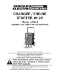
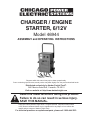
CHARGER / ENGINE
STARTER, 6/12V
Model 46944
ASSEMBLY and OPERATING INSTRUCTIONS
Diagrams within this manual may not be drawn proportionally.
Due to continuing improvements, actual product may differ slightly from the product described herein.
Distributed exclusively by Harbor Freight Tools®.
3491 Mission Oaks Blvd., Camarillo, CA 93011
Visit our website at: http://www.harborfreight.com
Read this material before using this product.
Failure to do so can result in serious injury.
Save this manual.
Copyright© 2002 by Harbor Freight Tools®. All rights reserved. No portion of this manual
or any artwork contained herein may be reproduced in any shape or form without the
express written consent of Harbor Freight Tools.
For technical questions or replacement parts, please call 1-800-444-3353.
Specifications
Amperage Output 40 amps at 6 Volts
(6 and 12 Volt)
100 amps at 6 Volts intermittent
2/10/40 amps at 12 Volts
200 amps at 12 Volts intermittent
Timer
3 Hour
Dimensions
16” W x 11-3/4” D x 31-3/4” H
Cable Clamps
3/4” W x 6-1/2” L (Copper), 3-3/4” L, Color Coded Vinyl Grip Sleeves, Red (Positive), Black (Negative)
Cable Length
79”
Save This Manual
You will need the manual for the safety warnings and precautions, assembly instructions,
operating and maintenance procedures, parts list and diagram. Keep your invoice with this
manual. Write the invoice number on the inside of the front cover. Keep the manual and
invoice in a safe and dry place for future reference.
Safety Warnings and Precautions
WARNING: When using tool, basic safety precautions should always be followed to
reduce the risk of personal injury and damage to equipment.
Read all instructions before using this tool!
1.
Keep work area clean. Cluttered areas invite injuries.
2.
Observe work area conditions. Do not use machines or power tools in damp or wet
locations. Don’t expose to rain. Keep work area well lighted. Do not use electrically
powered tools in the presence of flammable gases or liquids.
3.
Keep children away. Children must never be allowed in the work area. Do not let
them handle machines, tools, or extension cords.
4.
Store idle equipment. When not in use, tools must be stored in a dry location to
inhibit rust. Always lock up tools and keep out of reach of children.
5.
Do not force tool. It will do the job better and more safely at the rate for which it was
intended. Do not use inappropriate attachments in an attempt to exceed the tool
capacity.
6.
Use the right tool for the job. Do not attempt to force a small tool or attachment to
do the work of a larger industrial tool. There are certain applications for which this tool
was designed. Do not modify this tool and do not use this tool for a purpose for which
it was not intended.
7.
Dress properly. Do not wear loose clothing or jewelry as they can be caught in
moving parts. Protective, electrically nonconductive clothes and nonskid footwear are
recommended when working. Wear restrictive hair covering to contain long hair.
8.
Use eye protection. Always wear ANSI approved impact safety goggles.
SKU 46944
Page 2
REV 02d
9.
Do not overreach. Keep proper footing and balance at all times. Do not reach over or
across running machines.
10. Maintain tools with care. Keep tools clean for better and safer performance.
Inspect tool cords periodically, and if damaged, have them repaired by an authorized
technician. The handles must be kept clean, dry, and free from oil and grease at all
times.
11. Disconnect power. Unplug Charger Engine Starter when not in use.
12. Avoid unintentional starting. Be sure the switch is in the Off position when not in
use and before plugging in.
13. Stay alert. Watch what you are doing, use common sense. Do not operate any tool
when you are tired.
14. Check for damaged parts. Before using any tool, any part that appears damaged
should be carefully checked to determine that it will operate properly and perform its
intended function. Check for alignment and binding of moving parts; any broken parts
or mounting fixtures; and any other condition that may affect proper operation. Any
part that is damaged should be properly repaired or replaced by a qualified technician.
Do not use the tool if any switch does not turn On and Off properly.
15. Guard against electric shock. Prevent body contact with grounded surfaces such as
pipes, radiators, ranges, and refrigerator enclosures.
16. Replacement parts and accessories. No replacement parts available.
17. Do not operate tool if under the influence of alcohol or drugs. Read warning
labels on prescriptions to determine if your judgment or reflexes are impaired while
taking drugs. If there is any doubt, do not operate the tool.
18. Use proper size and type extension cord. If an extension cord is required, it must be
of the proper size and type to supply the correct current to the tool without heating up.
Otherwise, the extension cord could melt and catch fire, or cause electrical damage
to the tool. This tool requires use of an extension cord of 0 to 15 amps capability (up
to 25 feet), with wire size rated at 16 AWG. Longer extension cords require larger size
wire. If you are using the tool outdoors, use an extension cord rated for outdoor use
(signified by “WA” on the jacket).
19. Maintenance. For your safety, maintenance should be performed regularly by a
qualified technician.
20. People with pacemakers should consult their physician(s) before use.
Electromagnetic fields in close proximity to heart pacemaker could cause pacemaker
interference or pacemaker failure.
Note: Performance of this tool (if powered by line voltage) may vary depending on variations
in local line voltage. Extension cord usage may also affect tool performance.
Warning: The warnings, cautions, and instructions discussed in this instruction manual
cannot cover all possible conditions and situations that may occur. It must be understood
by the operator that common sense and caution are factors which cannot be built into
this product, but must be supplied by the operator.
SKU 46944
Page 3
REV 08j
Additional Battery Charger Safety Warnings:
1. Only use this Charger Engine Starter with lead acid, rechargeable type batteries.
Remove battery caps to check liquid level inside battery. If liquid is not present or if
liquid appears to be frozen, do not attempt to charge battery.
2. Do not use this Charger Engine Starter as a low voltage system power supply except
in automotive applications.
3. Do not try to start the automobile engine when the battery is still charging. It may
damage the unit.
4. Do not use this Charger Engine Starter to charge household dry cell batteries. Dry cell
batteries may explode causing personal injury and property damage.
5. Always charge lead acid batteries in well ventilated areas as explosive gases may be
produced during charging.
6. Place the Charger Engine Starter as far away as possible from the battery you are
charging.
7. Never attempt to charge a battery with frozen fluid.
8. Be careful not to drip any fluids in or around the Charger Engine Starter. Damage to
the Charger Engine Starter can occur.
9. Never touch the Charger Engine Starter cable clamps together when the charger is
plugged in; touching the cables together will cause sparking and possible personal
injury and/or property damage.
10. Do not touch your eyes after working with a lead acid battery. Wash your hands
thoroughly with soap and water.
11. If battery fluids contact your skin, face, or eyes, immediately flush with plenty of fresh
water, and then contact a doctor.
12. Never smoke around a charging battery.
13. Make all cable clamp connections before plugging in the Charger Engine Starter.
14. Remove all metal objects (including tools, personal objects such as a watch or jewelry)
from around the battery being charged.
15. Don’t use the Charger Engine Starter in damp or wet locations.
How Batteries Charge.
A charger doesn’t force current into a battery, but makes a limited amount available, and the
battery draws what it needs, up to or slightly greater than the output amp rating of the charger.
The closer the battery is to zero charge, the more current is drawn. Beginning with a dead
battery, the charger’s ammeter registers toward the high amp end, and falls toward zero as
charging progresses. Remember, the ammeter registers the amount of current being drawn
from the battery, not the delivery capability of the charger.
After the charger reaches 100% charge, it continues to draw on low level, converting it into
heat inside the battery. If left connected, after a full charge, the battery acid will eventually boil,
overcharging and damaging the battery.
Warning!! This Charger Engine Starter doesn’t have an automatic cut off. It is equipped with
a 2-1/2 hour timer. Always check the battery and the time manually. Don’t depend solely on
the timer. Leaving the Charger Engine Starter unattended can result in property damage and/
or personal injury.
SKU 46944
Page 4
Unpacking
When unpacking, check to make sure the parts listed on page 8 are included. If any parts
are missing or broken, please call Harbor Freight Tools at the number on the cover of this
manual as soon as possible.
Assembly
Refer to FIGURE 1 and FIGURE 2 below.
1. Place the Charger Engine Starter on its side.
2. Mount the Mounting Foot on the bottom using three screws.
FIGURE 2
FIGURE 1
Note: Wheel Hubs must face inward.
Handle
Axle Cap
Mounting Foot
Cord Cleats
Axle Bracket
3. Next, slide the Wheels on the Axle and put an Axle Cap on each wheel. Pound on the Axle
Caps with a rubber mallet. Make sure the Hubs are facing in on each wheel.
4. Line up the Axle Brackets with the holes on the bottom of the Charger and screw the Axle
Bracket to the bottom of the Charger Engine Starter.
5. Stand up the unit.
6. Remove the two top screws on each side of the Charger Engine Starter. Place the Handle
so it lines up with the screw holes, and replace the screws, securing the Handle.
7. Mount the six Cord Cleats using the remaining six screws.
Assembly complete.
Operation
1.
2.
Place the Charger Engine Starter at least five feet from the battery to be charged.
If the battery is to be charged in a vehicle, make sure the ignition is off and the key is
removed. Then, connect the positive (red with + sign) cable clamp to the positive (P or
+) terminal of the battery.
3. Connect the negative (Black with the - sign) to an unpainted solid metal portion of the
vehicle.
4. Set the Charger Engine Starter Switch to the proper setting for the type of battery being
charged. Refer to Table 1 on Page 6.
Caution: Make certain that vehicle’s ignition switch is off prior to turning on the charger. All
electrical accessories in the vehicle should be turned off.
5. With the battery clamps in place, and the Rotary Switch correctly set, plug the 3-prong
line cord into a grounded electrical outlet or extension cord.
6. The Charger Engine Starter is now supplying charging current to the battery. View the
Ammeter to see the amount of charging current. (The Ammeter displays the amount of
the “current draw” of the battery. As it charges, it draws less current. The Ammeter moves
toward zero as the battery charges.)
SKU 46944
Page 5
REV 02d; 09e
Operation (continued)
7.
8.
9.
After fully charging the battery, when the ammeter needle reads zero nearly, unplug the
Charger Engine Starter line cord from the outlet or extension cord.
Remove the negative (black) cable clamp from the battery.
Remove the positive (red) cable clamp from the battery.
Table 1
Battery Size / Rating
Charge Rate* / Charging Time Hours**
12V 2 Amp
Small Batteries Motorcycle
6 - 12 AH
3-6
Garden Tractor etc.
12 - 32 AH
3 - 18
200 - 315 CCA
40 - 60 RC
13 - 20
2-1/2 - 4
1/2 - 3/4
Cars / Trucks
315 - 550 CCA
60 - 85 RC
20- 35
4 - 7
3/4 - 2
550 - 875
85 - 125 RC
35 - 55
7 - 11
2-3
12V 10 Amp
12/6V 40 Amp
NR
NR
Notes: * Charge Rates for this model are listed on the front panel.
** Based on battery at 50% charge.
AH = Ampere Hours
NR = Not Recommended
CCA = Cold Cranking Amps
RC = Reserve Capacity
Warning!! This Charger Engine Starter is not automatic and can overcharge and dry up a
battery if permitted to operate for extended periods of time. Monitor the charging often.
Output Selector Controls
Charge Time / Minutes
(Timer)
Voltmeter
Volt / Amp Selector
(Rotary Switch)
Ammeter
Timer: The main function of the timer is to prevent over charging while allowing a battery time
to obtain a satisfactory charge. To properly set the timer, you must know the size of the battery
in ampere hours or reserve capacity in minutes, and the state of charge. Often the state of
charge is not known, which is one reason why the timer is limited to 3 hours. With the aid of
a battery load tester (not included) the state of the charge can be obtained in a few seconds.
For example, the average size automotive battery at a 50% state of charge will
SKU 46944
Page 6
REV 02d
Operation (continued)
require 1 to 1-1/2 hours of charging at the 40 amp rate to reach the full charge state. For the
same battery with its timer set to maximum, 3 hours overcharging will occur. Slight overcharging
will not likely harm a battery that was otherwise in good condition. When the state of charge
is unknown, start out with a timer setting of one hour or less.
Hold: This position defeats the timer function, allowing for continuous operation. Use it when
you want to charge more than 3 hours. This is normally used when the 2 amp charge rate
is selected. Be sure to monitor the charging and stop the charge when the battery is fully
charged.
Rotary Switch: Use the rotary switch to select the charge rate or engine start setting your
require. Read the switch dial for the appropriate setting.
Ammeter: The ammeter indicates the amount of current measured in amperes that’s drawn
from the battery. For example, in the 40 amp charge rate a typical discharged battery will initially draw approximately 40 amps. As the battery continues to charge, current will taper to 15
to 20 amps at full charge. When cranking an engine, the starter motor draws upward to 200
amps. The meter needle will be at the extreme right side. The 2 amp charge rate may indicate
some activity on the meter. The meter doesn’t have the resolution to display this low rate.
Voltmeter: Indicates the voltage at the battery terminals.
Engine Start
1.
2.
3.
4.
5.
6.
7.
Set the charge rate and timer to the off positions.
Turn off all electrical accessories in the vehicle.
With the Charger unplugged from the AC outlet, connect the Charger to the battery.
Plug the Charger AC power cord into the AC outlet, then move OFF to HOLD position.
Set the charge rate to the engine start position that matches the vehicle battery, and then
crank the engine. Follow the duty cycle printed on the front panel of your charger for
proper ON/OFF times. During extremely cold weather, or when the battery is severely
exhausted, charge the battery for about five minutes before attempting to crank the engine.
If the engine fails to start, charge the battery for five more minutes before cranking the
engine.
After the engine starts, move the charge rate switch to OFF and unplug the AC power
cord from the outlet before disconnecting the DC cable clamps.
Troubleshooting
Symptom: Ammeter display reads maximum.
Probable Cause: Defective battery.
Remedy: Check or replace battery.
Symptom: No ammeter reading.
Probable Cause: 1. No power to charge. 2. Battery cables not making connection.
3. Two amp charge rate being used.
Remedy: 1. Check power and cable outlet connections. 2. Clean battery cables and reset
cable clamps. 3. None, meter will not indicate here.
Symptom: Charging current not to full output.
Probable Cause: 1. Battery is partially charged. 2. Defective battery, will not hold full
charge.
Remedy: 1. Continue charging. 2. Check and/or replace battery.
SKU 46944
Page 7
REV 02d; 09e
Troubleshooting (continued)
Symptom: Ammeter needle moves up to full charge, then drops to zero. Makes clicking
noise.
Probable Cause: 1. Battery is completely dead. 2. Defective battery. 3. Charger Engine
Starter is resetting itself after circuit overload. 4. Circuit breaker is cycling. 5. Reverse connections at battery.
Remedy: 1. Continue charging battery. Charger Engine Starter will continue to reset itself
until the battery charge reaches a chargeable level. 2. Check and/or replace battery. 3. Wait
until Charger automatically resets itself. 4. May be the wrong switch position. 5. Shut off
Charger and correct cable lead connections.
Note: There are no replacement parts available with this Charger.
1.
2.
3.
4.
5.
6.
7.
8.
Accessories
Handle..................................1
Wheels.................................2
Axle......................................1
Mounting Foot......................1
Axle Brackets.......................2
Cord Cleats..........................6
Bag of Hardware..................1
Manual.................................1
NOTE: Some parts are listed and shown for illustration purposes only and are not available
individually as replacement parts.
PLEASE READ THE FOLLOWING CAREFULLY
THE MANUFACTURER AND/OR DISTRIBUTOR HAS PROVIDED THE PARTS DIAGRAM IN THIS
MANUAL AS A REFERENCE TOOL ONLY. NEITHER THE MANUFACTURER NOR DISTRIBUTOR MAKES ANY REPRESENTATION OR WARRANTY OF ANY KIND TO THE BUYER THAT
HE OR SHE IS QUALIFIED TO MAKE ANY REPAIRS TO THE PRODUCT OR THAT HE OR SHE
IS QUALIFIED TO REPLACE ANY PARTS OF THE PRODUCT. IN FACT, THE MANUFACTURER
AND/OR DISTRIBUTOR EXPRESSLY STATES THAT ALL REPAIRS AND PARTS REPLACEMENTS
SHOULD BE UNDERTAKEN BY CERTIFIED AND LICENSED TECHNICIANS AND NOT BY THE
BUYER. THE BUYER ASSUMES ALL RISK AND LIABILITY ARISING OUT OF HIS OR HER
REPAIRS TO THE ORIGINAL PRODUCT OR REPLACEMENT PARTS THERETO, OR ARISING
OUT OF HIS OR HER INSTALLATION OF REPLACEMENT PARTS THERETO.
SKU 46944
Page 8
LIMITED 90 DAY WARRANTY
Harbor Freight Tools Co. makes every effort to assure that its products meet high quality
and durability standards, and warrants to the original purchaser that this product is free from
defects in materials and workmanship for the period of 90 days from the date of purchase. This
warranty does not apply to damage due directly or indirectly, to misuse, abuse, negligence or
accidents, repairs or alterations outside our facilities, criminal activity, improper installation,
normal wear and tear, or to lack of maintenance. We shall in no event be liable for death, injuries to persons or property, or for incidental, contingent, special or consequential damages
arising from the use of our product. Some states do not allow the exclusion or limitation of
incidental or consequential damages, so the above limitation of exclusion may not apply to
you. This warranty is expressly in lieu of all other warranties, express
or implied, including the warranties of merchantability and fitness.
To take advantage of this warranty, the product or part must be returned to us with
transportation charges prepaid. Proof of purchase date and an explanation of the complaint
must accompany the merchandise. If our inspection verifies the defect, we will either repair or
replace the product at our election or we may elect to refund the purchase price if we cannot
readily and quickly provide you with a replacement. We will return repaired products at our
expense, but if we determine there is no defect, or that the defect resulted from causes not
within the scope of our warranty, then you must bear the cost of returning the product.
This warranty gives you specific legal rights and you may also have other rights which
vary from state to state.
3491 Mission Oaks Blvd. • PO Box 6009 • Camarillo, CA 93011 • (800) 444-3353
SKU 46944
Page 9
REV 08d