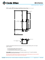
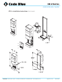
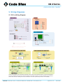
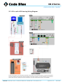
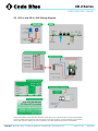
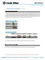
1
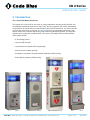
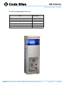
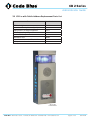
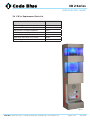
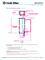
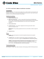
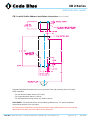
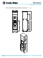
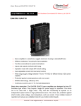
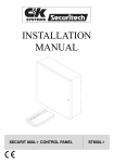
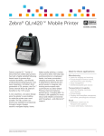
CB 2 Series CB 2-e CB 2-e with AED Housing CB 2-e with Public Address CB 2-s Installation & Setup Administrator Guide 800.205.7186 • www.codeblue.com CB 2 Series Administrator Guide Table of Contents SectionPage 2 Introduction....................................................................................3 3 Getting Started...............................................................................4 3.1 CB 2-e Replacement Parts List............................................5 3.2 CB 2-e with Public Address Replacement Parts List............6 3.3 Cb 2-e with AED Housing Replacement Parts List...............7 3.4 CB 2-s Replacement Parts List.............................................8 4 Installation Instructions.................................................................9 4.1 CB 2-e Installation Instructions.............................................9 4.2 CB 2-e with Public Address Installation Instructions...........13 4.3 Cb 2-e with AED Housing Installation Instructions..............16 4.4 CB 2-s Installation Instructions...........................................19 4.5 Pole Mount Bracket Installation Instructions.......................22 5 Wiring Diagrams...........................................................................23 5.1 CB 2-e Wiring Diagram.......................................................23 5.2 CB 2-e with Public Address Wiring Diagram.......................24 5.3 Cb 2-e with AED Housing Wiring Diagram..........................25 5.4 CB 2-s Wiring Diagram........................................................26 5.5 CB 2-e and CB 2-s PoE Wiring Diagram.............................27 6 Maintenance Schedule..................................................................28 6.1 CB 2-e with AED Housing Access and Maintenance...........30 7 Locating Unit Serial Numbers......................................................31 8 Warranty.........................................................................................32 9 Download Information...................................................................33 Code Blue • 259 Hedcor Street • Holland, MI 49423 USA • 800.205.7186 • www.codeblue.com page 2 of 33 GU-149-B CB 2 Series Administrator Guide 2 Introduction The 2 Series Wall Mount Help Points This popular line is a good fit for any indoor or outdoor application including parking facilities. Our unmistakable craftsmanship makes our Help Points® the most rugged on the market, withstanding the punishment of natural and man-made disasters. With durable construction, our wall mount units can meet any requirement or purpose. All 2 Series units have a rugged steel construction, shatterproof Lexan Lens, industrial engineering grade reflective graphics and weather, UV and graffiti resistant paint. Lighting with a high-powered, 270 lumens / 92 candela LED blue beacon/strobe. Other options include: • IP and analog phones • Long-life LED area light • Low powered consumption LED faceplate light • Camera and card reader openings • Temperature controlled automated external defibrillator (AED) housing • Public address speakers (PAS) housing CB 2-e CB 2-e with Public Address CB 2-e with AED Housing Code Blue • 259 Hedcor Street • Holland, MI 49423 USA • 800.205.7186 • www.codeblue.com CB 2-s page 3 of 33 GU-149-B CB 2 Series Administrator Guide 3 Getting Started Basic Install Instructions 1. EIA/TIA, ANSI, CSA and BICSI cabling or similar standards shall be adhered to for proper operation of Code Blue communication devices connected to copper or fiber infrastructures. Communications cable and electrical cable in the same conduit is not an acceptable installation and shall not be supported. Analog phones require a minimum of 23mA for proper operation (26-29mA recommended). 2. Each analog speakerphone requires its own phone line or PBX extension. Multiple units shall not be supported. 3. Speakerphones require programming before operation. Consult the User Guide or Administrator Guide enclosed with the unit or go to www.codeblue.com > Support > Downloads to read or download manuals. 4. If you are installing IP speakerphones, please read the appropriate manuals and consult with your Network Administrator. 5. Size electrical wiring based on length of run. 6. Consult the enclosed document packet for internal wiring instructions. What’s Included Quantity Part Description 1 Document packet (Installation and Setup) 1 Hardware packet 4 Lag screw sleeves 4 Metal washers 4 Rubber washers 1 Security bit 1 Enclosure (CB 2-e, CB 2-e with PAS, CB 2-e with AED or CB 2-s) 2 Faceplate screws – CB 2-s only 2 Key fobs – CB 2-e with AED only Code Blue • 259 Hedcor Street • Holland, MI 49423 USA • 800.205.7186 • www.codeblue.com page 4 of 33 GU-149-B CB 2 Series Administrator Guide 3.1 CB 2-e Replacement Parts List Part Part Number LED Strobe Light 40159 Button Head Security Screws (3 pack) 41418 Analog Phone Line Surge Suppressor 41471 IP Phone Line Surge Suppressor 41421 Manifold R/B 5-way 40101 Power Brick 120V, 240V, 277V, & 347V 40104 CB 2-e Code Blue • 259 Hedcor Street • Holland, MI 49423 USA • 800.205.7186 • www.codeblue.com page 5 of 33 GU-149-B CB 2 Series Administrator Guide 3.2 CB 2-e with Public Address Replacement Parts List Part Part Number LED Strobe Light 40159 Button Head Security Screws (3 pack) 41418 Analog Phone Line Surge Suppressor 41471 IP Phone Line Surge Suppressor 41421 Manifold R/B 5-way 40101 PAS AMP Kit 24V 40009 Power Brick 120V, 240V, 277V, & 347V 40104 PAS Speaker 40080 CB 2-e with Public Address Code Blue • 259 Hedcor Street • Holland, MI 49423 USA • 800.205.7186 • www.codeblue.com page 6 of 33 GU-149-B CB 2 Series Administrator Guide 3.3 CB 2-e with AED Housing Replacement Parts List Part Part Number LED Strobe Light 40159 Button Head Security Screws (3 pack) 41418 Analog Phone Line Surge Suppressor 41471 IP Phone Line Surge Suppressor 41421 Manifold R/B 5-way 40101 Power Brick 120V, 240V, 277V, & 347V 40104 AED Housing Door Release Mechanism 41104 AED Housing Heater 41105 AED Housing Thermostat 41106 AED Housing Door Controller 41107 AED Housing Retrofit kit 40012 CB 2-e with AED Housing Code Blue • 259 Hedcor Street • Holland, MI 49423 USA • 800.205.7186 • www.codeblue.com page 7 of 33 GU-149-B CB 2 Series Administrator Guide 3.4 CB 2-s Replacement Parts List Part Part Number LED Strobe Light 40159 Button Head Security Screws (3 pack) 41418 Analog Phone Line Surge Suppressor 41471 IP Phone Line Surge Suppressor 41421 Manifold R/B 5-way 40101 Power Brick 120V, 240V, 277V, & 347V 40104 LED Area Light 41539 CB 2-s Code Blue • 259 Hedcor Street • Holland, MI 49423 USA • 800.205.7186 • www.codeblue.com page 8 of 33 GU-149-B CB 2 Series Administrator Guide 4 Installation Instructions 4.1 CB 2-e Installation Instructions Pre-Installation Electrical preparation – The unit may have supply wires run either behind the unit through the wall or below the unit by using an external conduit through the bottom of the unit. Holes in the back and the bottom of the unit have been provided for this purpose. Installation Procedures 1. Remove the top of the unit. 2. Mark the mounting holes – In order to comply with the Americans with Disabilities Act (ADA) of 1990, the speakerphone button(s) should be positioned between 34 and 48 inches from grade level. (Consult an ADA specialist in your area to verify local and federal guidelines.) 3. Drill all marked holes. 4. Install the housing – Four anchors of appropriate size and type should be used to fasten the housing to the wall. IMPORTANT: If wiring is being supplied from the back, ensure that the conduit is aligned at this time. 5. Reattach the top. Wiring 1. Ground – The ground (green) wire should be stripped and fastened to the supplied grounding lug. 2. 12-24V AC / DC - The enclosure comes pre-wired, except for incoming power. Bring incoming power to the harness or pigtails. A Certified Electrician should do any wiring. 120V AC – The enclosure comes pre-wired except for incoming power. If you are using a Code Blue Power Supply/Transformer, please look at the wiring diagram on top of the Step Down Transformer to verify how to step down the voltage that you are bringing to the enclosure. A Certified Electrician should do any wiring. Code Blue • 259 Hedcor Street • Holland, MI 49423 USA • 800.205.7186 • www.codeblue.com page 9 of 33 GU-149-B CB 2 Series Administrator Guide CB 2-e Additional Options HIKVISION Network Mini Dome Camera The HIKVISION Mini Dome Network IP Camera installed in this unit is a Code Blue 3rd Party Partner product. Model # DS-2CD7153-E. The network camera is set with the following factory default settings: 1. 2. 3. 4. IP Address: 192.0.0.64 Camera is accessed on IP Port 8000 User Name: admin Password: 12345 For additional support, contact HIKVISION at: 1. Website: http://www.hikvision-usa.com/support.html 2. Phone: 1-909-895-0400, 6 a.m. to 6 p.m. PST 3. Email: [email protected] Note: Please contact Code Blue Customer Service if a custom cutout is needed in the CB 2-e for third party products, such as a card reader or a custom camera to mount inside the CB 2-e enclosure. Contact Code Blue Customer Service at 1-800-205-7186 or [email protected]. Code Blue • 259 Hedcor Street • Holland, MI 49423 USA • 800.205.7186 • www.codeblue.com page 10 of 33 GU-149-B CB 2 Series Administrator Guide CB 2-e Installation Instructions (continued) Code Blue • 259 Hedcor Street • Holland, MI 49423 USA • 800.205.7186 • www.codeblue.com page 11 of 33 GU-149-B CB 2 Series Administrator Guide CB 2-e Installation Instructions (continued) Suggested installation dimensions shown from ground to lower right mounting hole are for single button faceplates. • For dual button faceplate, deduct 3.25 inches. • For keypad faceplate, deduct 4.5 inches. • For wheelchair direct facing access only, deduct 6 inches. DISCLAIMER: The dimensions above are intended as guidelines only. For specific installation requirements reference your local codes. All wiring must be installed and connected by experienced and certified personnel to meet local and national electrical codes, and will include a service disconnect. Code Blue • 259 Hedcor Street • Holland, MI 49423 USA • 800.205.7186 • www.codeblue.com page 12 of 33 GU-149-B CB 2 Series Administrator Guide 4.2 CB 2-e with Public Address Installation Instructions Pre-Installation Electrical preparation – The unit may have supply wires run either behind the unit through the wall or below the unit by using an external conduit through the bottom of the unit. Holes in the back and the bottom of the unit have been provided for this purpose. Installation Procedures 1. Remove the top of the unit. 2. Mark the mounting holes – In order to comply with the Americans with Disabilities Act (ADA) of 1990, the speakerphone button(s) should be positioned between 34 and 48 inches from grade level. (Consult an ADA specialist in your area to verify local and federal guidelines.) 3. Drill all marked holes. 4. Install the housing – Four anchors of appropriate size and type should be used to fasten the housing to the wall. IMPORTANT: If wiring is being supplied from the back, ensure that the conduit is aligned at this time. 5. Reattach the top. Wiring 1. Ground – The ground (green) wire should be stripped and fastened to the supplied grounding lug. 2. 12-24V AC / DC - The enclosure comes pre-wired, except for incoming power. Bring incoming power to the harness or pigtails. A Certified Electrician should do any wiring. 120V AC – The enclosure comes pre-wired except for incoming power. If you are using a Code Blue Power Supply/Transformer please look at the wiring diagram on top of the Step-Down Transformer to verify how to step down the voltage that you are bringing to the enclosure. A Certified Electrician should do any wiring. Communications Wiring Have category 3 or higher 4 pair cable terminated to a RJ45 applying TIA/EIA T568-B specifications. Code Blue • 259 Hedcor Street • Holland, MI 49423 USA • 800.205.7186 • www.codeblue.com page 13 of 33 GU-149-B CB 2 Series Administrator Guide CB 2-e with Public Address Installation Instructions (continued) Code Blue • 259 Hedcor Street • Holland, MI 49423 USA • 800.205.7186 • www.codeblue.com page 14 of 33 GU-149-B CB 2 Series Administrator Guide CB 2-e with Public Address Installation Instructions (continued) Suggested installation dimensions shown from ground to lower right mounting hole are for single button faceplates. • For dual button faceplate, deduct 3.25 inches. • For keypad faceplate, deduct 4.5 inches. • For wheelchair direct facing access only, deduct 6 inches. DISCLAIMER: The dimensions above are intended as guidelines only. For specific installation requirements reference your local codes. All wiring must be installed and connected by experienced and certified personnel to meet local and national electrical codes, and will include a service disconnect. Code Blue • 259 Hedcor Street • Holland, MI 49423 USA • 800.205.7186 • www.codeblue.com page 15 of 33 GU-149-B CB 2 Series Administrator Guide 4.3 CB 2-e with AED Housing Installation Instructions Pre-Installation Electrical preparation – The unit may have supply wires run either behind the unit through the wall or below the unit by using an external conduit through the bottom of the unit. Holes in the back and bottom of the unit have been provided for this purpose. Installation Procedures 1. Remove the top of the unit. 2. Mark the mounting holes – In order to comply with the Americans with Disabilities Act (ADA) of 1990, the speakerphone button(s) should be positioned between 34 and 48 inches from grade level. (Consult an ADA specialist in your area to verify local and federal guidelines.) 3. Drill all marked holes. 4. Install the housing – Four anchors of appropriate size and type should be used to fasten the housing to the wall. IMPORTANT: If wiring is being supplied from the back, ensure that the conduit is aligned at this time. 5. Reattach the top. Wiring 120/240V AC supply – Feed the incoming power leads into the supplied J-Box. Connect the ground to the supplied grounding lug. Connect the neutral to the orange lead for fusing the unit. Connect the load to the black wires. After completing the wire connections, install the supplied J-Box cover and ensure all cord grips are secure. Code Blue • 259 Hedcor Street • Holland, MI 49423 USA • 800.205.7186 • www.codeblue.com page 16 of 33 GU-149-B CB 2 Series Administrator Guide CB 2-e with AED Housing Installation Instructions (continued) 12.53 8.00 36.00 46.72 21.00 23.06 3.00 15.5 9.00 11 Code Blue • 259 Hedcor Street • Holland, MI 49423 USA • 800.205.7186 • www.codeblue.com page 17 of 33 GU-149-B CB 2 Series Administrator Guide CB 2-e with AED Housing Installation Instructions (continued) Ø .44 MOUNTING HOLES 4 PLCS 45.22 36.00 Ø 1.13 KNOCKOUTS FOR Ø 3/4 CONDUIT 2 PLCS 8.00 21.00 3.00 BOTTOM 9.00 12.40 28.00 GROUND LEVEL 2.20 REF 8.00 1.62 MOUNTING SURFACE Ø 1.13 THRU BOTTOM PLATE FOR Ø 3/4 CONDUIT 2 PLCS Suggested installation dimensions shown from ground to lower right mounting hole are for single button faceplates. • For dual button faceplate, deduct 3.25 inches. • For keypad faceplate, deduct 4.5 inches. • For wheelchair direct facing access only, deduct 6 inches. DISCLAIMER: The dimensions above are intended as guidelines only. For specific installation requirements reference your local codes. All wiring must be installed and connected by experienced and certified personnel to meet local and national electrical codes, and will include a service disconnect. Code Blue • 259 Hedcor Street • Holland, MI 49423 USA • 800.205.7186 • www.codeblue.com page 18 of 33 GU-149-B CB 2 Series Administrator Guide 4.4 CB 2-s Installation Instructions Pre-Installation Electrical preparation – The unit may have supply wires run either behind the unit through the wall or below the unit by using an external conduit through the bottom of the unit. Holes in the back and the bottom of the unit have been provided for this purpose. Installation Procedures 1. Remove the light bracket and outer shell from the back plate. 2. Mark the mounting holes – In order to comply with the Americans with Disabilities Act (ADA) of 1990, the speakerphone button(s) should be positioned between 34 and 48 inches from grade level. (Consult an ADA specialist in your area to verify local and federal guidelines.) 3. Install the back plate – Four anchors should securely fasten the back plate to the wall. IMPORTANT: If wiring is coming in from the back, ensure that the conduit is aligned at this time. 4. Reattach the light bracket. 5. Reattach the outer shell – Holding the shell horizontal, hook the bottom hinge into the bottom of the back plate. Swing the shell up and fasten the safety cable to the eyehook. 6. Connect electrical and communications wiring (see wiring instructions). 7. Close the unit – Fasten the outer shell to the back plate using two #10 countersunk security screws. Wiring 1. Ground – The ground (green) wire should be stripped and fastened to the supplied grounding lug. 2. 12-24V AC / DC - The enclosure comes pre-wired, except for incoming power. Bring incoming power to the harness or pigtails. A Certified Electrician should do any wiring. 120V AC – The enclosure comes pre-wired, except for incoming power. If you are using a Code Blue Power Supply/Transformer, please look at the wiring diagram on the top of the Step-Down Transformer to verify how to step down the voltage that you are bringing to the enclosure. A Certified Electrician should do any wiring. Code Blue • 259 Hedcor Street • Holland, MI 49423 USA • 800.205.7186 • www.codeblue.com page 19 of 33 GU-149-B CB 2 Series Administrator Guide CB 2-s Installation Instructions (continued) Code Blue • 259 Hedcor Street • Holland, MI 49423 USA • 800.205.7186 • www.codeblue.com page 20 of 33 GU-149-B CB 2 Series Administrator Guide CB 2-s Installation Instructions (continued) 12 REF 4 X Ø7/16 MOUNTING HOLES 30 3/4 42 REF 2 X Ø1-1/8 (KNOCKOUTS FOR Ø3/4 CONDUIT) 2 9/16 8 5/16 REF 1 1/2 REF 6 1 1/2 9 43 GROUND/FLOOR Suggested installation dimensions shown from ground to lower right mounting hole are for single button faceplates. • For dual button faceplate, deduct 3.25 inches. • For keypad faceplate, deduct 4.5 inches. • For wheelchair direct facing access only, deduct 6 inches. DISCLAIMER: The dimensions above are intended as guidelines only. For specific installation requirements reference your local codes. All wiring must be installed and connected by experienced and certified personnel to meet local and national electrical codes, and will include a service disconnect. Code Blue • 259 Hedcor Street • Holland, MI 49423 USA • 800.205.7186 • www.codeblue.com page 21 of 33 GU-149-B CB 2 Series Administrator Guide 4.5 Pole Mount Bracket Installation Instructions 1. Thread the mounting straps through the slots; use the outside slots for larger poles and inside slots for smaller poles. 2. Hold bracket to pole; Set the height of the bracket (C) so the speakerphone push button(s) on the unit will be at desired height (please check with local codes for ADA compliance). 3. Band the bracket to the pole at desired height. To eliminate waste, pull band (A) from carton as needed. With ears of buckle (B) away from operator, slide the buckle on the banding. Lace banding around the object being clamped and again through buckle. 4. Bend end of band under buckle. 5. Slide band in tool nose slot. Press down on gripper with thumb and tension clamp by turning the handle. Maximum tension has been reached when the band stops moving through the buckle. 6. When maximum tension has been reached, roll tool over buckle. At same time reverse the handle carefully, with approximately a three-quarter turn to avoid breakage. The band that is released will be used in the bend, therefore there is no loss of tension. 7. Lift cutter lever and band will be cut to correct length. While holding the stub of the band with your thumb, hammer flat over bridge of buckle. 8. Complete application by hammering the buckle ears over the stub. 9. Attach enclosure to bracket. Place a rubber washer (D) on each of the four studs. 10. Place a second set of rubber washers on to each of the four studs (inside the unit). 11. Place a steel washer (E) on each of the four studs. 12. Turn a nut (F) on each of the four studs. C D F E B A C B 2 - E B AC K P L AT E Note: All wiring must be installed and connected by experienced and certified personnel to meet local and national electrical codes, and will include a service disconnect. Specifications subject to change without notice or obligation on the part of the manufacturer. Code Blue • 259 Hedcor Street • Holland, MI 49423 USA • 800.205.7186 • www.codeblue.com page 22 of 33 GU-149-B CB 2 Series Administrator Guide 5 Wiring Diagrams 5.1 CB 2-e Wiring Diagram Product wiring diagram shown reasonably represents current offering and is intended to assist in component identification and service. Earlier product production may have different components and wiring connections. Reference the model and serial number from the unit ID tag and contact manufacturer to confirm replacement part version and availability. Code Blue • 259 Hedcor Street • Holland, MI 49423 USA • 800.205.7186 • www.codeblue.com page 23 of 33 GU-149-B CB 2 Series Administrator Guide PAS 2-e Wiring Diagram 5.2 CB 2-e with Public Address Wiring Diagram LIGHTING POWER SUPPLY Beacon/Strobe 12-24V AC or DC MULTI-TAP • Multi-Tap LV fuses are generally 2A GMA LED Faceplate Light 12-24V AC or DC 12V DC 24V AC 120, 240, 277, 347 V AC @ 250 VA CB 2-E with Public Address SPEAKER/AMP POWER MANIFOLD PAS Gen2 Amp 24V AC @ 3 Amps Common or Neg 12-24V AC or DC + - PAS Audio PAS Control phone specific NOTE: Use the supplied modular inter-connects to link the unit’s various powered devices. IA4100 COMMUNICATION CONNECTIONS IP5000 COMMUNICATION CONNECTIONS 11751 GRD Fiber Converter One pair modular POTS line RJ-11 cord + - G +- IP5000 SPEAKERPHONE OUTPUT 1 3 1 Cat 5e or 6 Copper Cat 6 IA4100 SPEAKERPHONE ACC BATT AUX INPUTS POWER Ethernet Surge Protector Fiber Fiber to FXS (ATA) Converter Fiber GRD 2 3 PAS CONTROL PAS AUDIO PWR BATT 2 N.O. 4 N.C. LAN PoE LAN 1 LAN 2 +- +- AUX PORTS PAS PAS CONTROL AUDIO 1 Aux Aux Input Input 2 1 12-24V AC or DC standard 1 Audio Output Chassis Ground Battery 12V @ 2.0Ahr Phone Line Aux Output 1 12-24V AC or DC standard Aux Aux Output Input 2 1 AUDIO OUTPUT Battery 12V @ 2.0Ahr Product wiring diagram shown reasonably represents current offering and is intended to assist in component identification and service. Earlier product production may have different components and wiring connections. Reference the model and serial number from the unit ID tag and contact manufacturer to confirm replacement part version and availability. Product wiring diagram shown reasonably represents current offering and is intended to assist in component identification Code and Blueservice. MI 49423 USA different • 259 Hedcor • Holland, • 800.205.7186 • www.codeblue.com EarlierStreet product production may have components and wiring connections. Reference the model and WD-117-B serial number from the unit ID tag and contact manufacturer to confirm replacement part version and availability. Code Blue • 259 Hedcor Street • Holland, MI 49423 USA • 800.205.7186 • www.codeblue.com page 24 of 33 GU-149-B CB 2 Series Administrator Guide 5.3 CB 2-e with AED Housing Wiring Diagram AED Housing AED Housing Product wiring diagram shown reasonably represents current offering and is intended to assist in component identification and service. Earlier product production may have different components and wiring connections. Reference the model and serial number from the unit ID tag and contact manufacturer to confirm replacement part version and availability. Code Blue • 259 Hedcor Street • Holland, MI 49423 USA • 800.205.7186 • www.codeblue.com page 25 of 33 GU-149-B CB 2 Series Administrator Guide 5.4 CB 2-s Wiring Diagram Product wiring diagram shown reasonably represents current offering and is intended to assist in component identification and service. Earlier product production may have different components and wiring connections. Reference the model and serial number from the unit ID tag and contact manufacturer to confirm replacement part version and availability. Code Blue • 259 Hedcor Street • Holland, MI 49423 USA • 800.205.7186 • www.codeblue.com page 26 of 33 GU-149-B CB 2 Series Administrator Guide 5.5 CB 2-e and CB 2-s PoE Wiring Diagram Product wiring diagram shown reasonably represents current offering and is intended to assist in component identification and service. Earlier product production may have different components and wiring connections. Reference the model and serial number from the unit ID tag and contact manufacturer to confirm replacement part version and availability. Code Blue • 259 Hedcor Street • Holland, MI 49423 USA • 800.205.7186 • www.codeblue.com page 27 of 33 GU-149-B CB 2 Series Administrator Guide Maintenance Schedule 6 Maintenance Schedule Guidelines LEGEND G Guard tasks T Technician tasks DAILY OR WEEKLY G Perform functional communications check Action: Press red button Strobe activates Red LED “Call Placed” light turns on Message plays Call connects, green LED “Call Received” light turns on Confirm conversation clarity with dispatch MONTHLY OR QUARTERLY G Visually check lighting functions: Faceplate light Beacon G Visually inspect unit for damage to: Faceplate Piezo button Microphone (pest infestation, damage or obstructions) Speaker (pest infestation, damage or obstructions) T Check batteries Functioning with full charge Recharging fully, including NightCharge®/Solar units (NOTE: recommend mid- to late afternoon inspection) Strobe BIANNUALLY T Remove access door and faceplate assembly to inspect the following: Ensure all electrical connections are secure Check all phone connections for corrosion (If corroded, clean and coat with dielectric gel or replace) Ensure all battery connections are tight and clean Verify no stains exist around gasket areas (Stains indicate leaking and gasket should be replaced) Verify moisture weep hole on cabinet bottom is open and unobstructed Verify bottom of bollards are at least 1/2 inch above footing and free of obstructions (Applies to CB 1, CB 5 and CB 9 units) G Apply automotive paint sealant to unit exterior for protecting finish against environmental pollutants (Suggested products include Black Magic Wet Shine Liquid Wax, Nu Finish NFP-80, and 5 Star Shine ) G Clean and coat exterior stainless steel cabinets with cleaner/polish (Suggested products include Chase Products' Champion Sprayon Stainless Steel Cleaner to help protect finish against environmental pollutants) T Visually confirm line-of-sight is still clear to base station (i.e., confirm that new tree growth, new building construction or other obstructions are not blocking view of base station) ANNUALLY T Replace batteries used with NightCharge, cellular or RF systems (Replace with like batteries as recommended by the communication manufacturer to ensure optimal performance) Code Blue • 259 Hedcor Street • Holland, MI 49423 USA • 800.205.7186 • www.codeblue.com Code Blue • 259 Hedcor Street • Holland, MI 49423 USA • 800.205.7186 • www.codeblue.com page 28 of 33 IN-174-A GU-149-B CB 2 Series Administrator Guide Maintenance Schedule Maintenance Schedule (continued) Guidelines UNIT SURFACE MAINTENANCE The painted and stainless steel Code Blue models require periodic care to sustain their aesthetic appearance. Units located outdoors are vulnerable to harsh environmental conditions, including UV rays, acid rain, diesel fumes and airborn iron particles (i.e., dust) which over time may cause unit discoloring. To prevent pollutants developing harmful chemical reactions on Code Blue units, an appropriate surface maintenance schedule should be adhered to. The Surface Care Frequency table below provides general guidelines to assist in configuring a schedule. Please note that the frequency of care required to guard the Code Blue unit’s surface from damage will also be dictated by local environmental characteristics. LEGEND: POLLUTANTS LEVEL Low Low/Moderate Moderate Moderate/High High ê êê êêê êêêê êêêêê SURFACE CARE FREQUENCY MONTHLY Painted Stainless Steel êêêêê BIMONTHLY QUARTERLY êêêêê êêêê êêêê êêê BIANNUAL ANNUAL êêê ê ê See scheduled tasks under Biannually on page 28 for suggested paint sealants or stainless steel cleaners. AVERAGE COMPONENT LIFE Component life is based on various mechanical, operational and environmental factors. Your local Code Blue dealer can assist you with a regularly scheduled maintenance program customized to your individual site requirements. Code Blue strongly recommends contacting a local CB dealer to establish a proactive maintenance schedule. Code Blue strongly recommends contacting a local CB dealer to establish a proactive maintenance schedule. page 29 of 33 Code Blue • 259 Hedcor Street MI 49423 USA • 800.205.7186 • Holland, • www.codeblue.com Code Blue • 259 Hedcor Street • Holland, MI 49423 USA • 800.205.7186 • www.codeblue.com pg. 2 of 2 GU-149-B CB 2 Series Administrator Guide 6.1 CB 2-e with AED Access and Maintenance The following methods can be used to access the Automated External Defibrillator (AED) device: 1. When the red button is depressed the unit will make a call. After the call has been answered, the answering party can then depress the 6 key on their telephone keypad. This will release the door latch, giving the caller access to the AED device. 2. The units have a key fob supplied at the time of purchase. This key fob can be used within a 20-foot radius to release the door latch, giving the caller access to the AED device. 3. The unit can be called and placed into two-way monitor mode. At this time, the person calling the unit can depress the 6 key on their telephone keypad, which will provide access to the AED device. 4. The access panel on the back of the Code Blue unit is removed and the manual latch release is pulled, granting access to the AED device. Typically, AED manufacturers recommend that the device be checked once per week for proper operation. Some units will give an audible “chirp” if the self-diagnostics have failed and the unit needs service. Others may use another indicator to verity its status. Refer to manufacturer’s maintenance instructions for correct diagnostic testing to ascertain whether the device requires service or not. In addition, review the manufacturer’s replacement policy for pad and battery replacement. Pay close attention to the AED temperature specifications and consider the life of the AED battery, which can be greatly affected by extreme heat or cold environments and reduce the capacity by up to 50 percent. Code Blue • 259 Hedcor Street • Holland, MI 49423 USA • 800.205.7186 • www.codeblue.com page 30 of 33 GU-149-B CB 2 Series Administrator Guide 7 Locating Unit Serial Numbers Remove the speakerphone faceplate with the special security bit. The serial number will be listed on the manufacturer’s label located inside the unit (1). 1 Code Blue • 259 Hedcor Street • Holland, MI 49423 USA • 800.205.7186 • www.codeblue.com page 31 of 33 GU-149-B CB 2 Series Administrator Guide 8 Warranty Code Blue Corporation provides a limited warranty on this product. Refer to your sales agreement to establish the terms of the limited warranty. In addition, Code Blue’s standard warranty language as well as information regarding support for this product, while under warranty, is available through the following website: www.codeblue.com. Code Blue • 259 Hedcor Street • Holland, MI 49423 USA • 800.205.7186 • www.codeblue.com page 32 of 33 GU-149-B CB 2 Series Administrator Guide 9 Download Information Download Information Main Location: http://codeblue.com/support/downloads/ Code Blue now has a centralized location where you can find all the Installation, Setup, Information, Configuration & Operation instructions. 1. IA4100 Installation & Setup: http://codeblue.com/resources/admin-guides/ 2. IA4100 Configuration & Operation: http://codeblue.com/resources/user-guides/ 3. IP5000 Installation & Setup: http://codeblue.com/resources/admin-guides/ 4. IP5000 Configuration & Operation: http://codeblue.com/resources/user-guides/ 5. IP1500 Installation & Setup: http://codeblue.com/resources/admin-guides/ 6. IP1500 Configuration & Configuration: http://codeblue.com/resources/user-guides/ 7. IP2500 Installation & Setup: http://codeblue.com/resources/admin-guides/ 8. IP2500 Configuration & operation: http://codeblue.com/resources/user-guides/ 9. IA500 Installation & Setup: http://codeblue.com/resources/admin-guides/ 10. IA500 Configuration & Operation: http://codeblue.com/resources/user-guides/ 11. ToolVox Administrator Guide: http://codeblue.com/resources/admin-guides/ 12. ToolVox UPD Configuration & Operation: http://codeblue.com/resources/user-guides/ 13. ToolVox Quick Start: http://codeblue.com/wp-content/uploads/2014/02/in-181_ToolVox_Quick_Start.pdf 14. Public Address Administrator Guide: http://codeblue.com/resources/admin-guides/ 15. Blue Alert MNS Configuration & Operation: http://codeblue.com/resources/user-guides/ 16. Blue Alert EMS Configuration & Operation: http://codeblue.com/resources/user-guides/ 17. Blue Alert Mobile Powered by Guardly: http://codeblue.com/resources/user-guides/ 18. S-1000 LED Strobe Configuration & Operation: http://codeblue.com/resources/user-guides/ 19. IP5000 1.0 Series User Guides: http://codeblue.com/resources/user-guides/ 20. IP1500 and IP2500 Firmware: http://codeblue.com/support/downloads/ 21. IP5000 Versions 1.X & 2.X Firmware: http://codeblue.com/support/downloads/ For Legacy IA3100 Information: 1. http://codeblue.com/wp-content/uploads/2013/12/gu-146_IA3100_Admin_Guide.pdf 2. http://codeblue.com/wp-content/uploads/2013/12/gu-145_IA3100_User_Guide.pdf These Administrator and User Guides should contain all the information needed for your application. If further information is needed please contact [email protected]. Code Blue • 259 Hedcor Street • Holland, MI 49423 USA • 800.205.7186 • www.codeblue.com page 33 of 33 GU-149-B