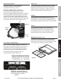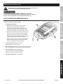
1
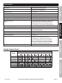
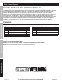
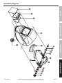
Table of Contents
Safety.......................................................... 3
Specifications.............................................. 5
Operation..................................................... 6
Maintenance................................................ 9
Parts List and Diagram............................... 10
Warranty..................................................... 12
SAFETY
SPECIFICATIONS
WARNING SYMBOLS AND DEFINITIONS
This is the safety alert symbol. It is used to alert you to potential personal injury hazards.
Obey all safety messages that follow this symbol to avoid possible injury or death.
Indicates a hazardous situation which, if not avoided,
will result in death or serious injury.
Indicates a hazardous situation which, if not avoided,
could result in death or serious injury.
Indicates a hazardous situation which, if not avoided,
could result in minor or moderate injury.
Addresses practices not related to personal injury.
OPERATION
MAINTENANCE
Page 2
For technical questions, please call 1-800-444-3353.
Item 67854
IMPORTANT SAFETY INFORMATION
The warnings, cautions, and instructions discussed in this instruction manual cannot cover all possible
conditions and situations that may occur. It must be understood by the operator that common sense
and caution are factors which cannot be built into this product, but must be supplied by the operator.
Read all instructions before using this helmet!
Use natural or forced air ventilation and
wear a respirator approved by NIOSH to
protect against the fumes produced to
reduce the risk of developing the above
illnesses.
1. Do not use the Welding Helmet if the lens is
cracked, if the lens or sensors are dirty, or if
the lens or front retaining frame is loose.
2. Keep work area clean. Cluttered
areas invite injuries.
3. Observe work area conditions. Do not use
welding helmets in damp or wet locations.
Do not expose to rain. Keep work area well
lit. Do not use auto-darkening helmets in the
presence of flammable gases or liquids.
Item 67854
6. Dress properly. Do not wear loose clothing or
jewelry as they can be caught in moving parts.
Protective gear is essential to protect against welding
rays, some examples are: a leather welding apron,
welding sleeves, jeans without cuffs, work boots.
Wear restrictive hair covering to contain long hair.
SPECIFICATIONS
Exposure to welding or cutting exhaust
fumes can increase the risk of developing
certain cancers, such as cancer of the
larynx and lung cancer. Also, some
diseases that may be linked to exposure
to welding or plasma cutting exhaust
fumes are:
•Early onset of Parkinson’s Disease
•Heart disease
• Ulcers
•Damage to the reproductive organs
•Inflammation of the small intestine or
stomach
• Kidney damage
•Respiratory diseases such as
emphysema, bronchitis, or pneumonia
5. Store idle equipment. When not in use, helmets
must be stored in a dry location to inhibit rust. Always
lock up helmets and keep out of reach of children.
7. Use eye and ear protection. When welding,
wear ANSI-approved impact safety goggles under
the Welding Helmet. Wear a NIOSH-approved
respirator and hearing protection when welding.
8. Stay alert. Watch what you are doing, use
common sense. Do not weld when you are tired.
9. Check for damaged parts. Before using any
helmet, any part that appears damaged should be
carefully checked to determine that it will operate
properly and perform its intended function. Check
for alignment and binding of moving parts; any
broken parts or mounting fixtures; and any other
condition that may affect proper operation. Any part
that is damaged should be properly repaired or
replaced by a qualified technician. Do not use the
helmet if any switch does not operate properly.
10. Replacement parts and accessories. When
servicing, use only identical replacement parts. Use
of any other parts can render helmet ineffective,
possibly causing eye damage, and will void
the warranty. Only use accessories intended
for use with this helmet. Approved accessories
are available from Harbor Freight Tools.
11. Do not weld if under the influence of alcohol
or drugs. Read warning labels on prescriptions to
determine if your judgment or reflexes are impaired
while taking drugs. If there is any doubt, do not weld.
12. Maintenance. For your safety, service
and maintenance should be performed
regularly only by a qualified technician.
For technical questions, please call 1-800-444-3353.
Page 3
OPERATION
INHALATION HAZARD:
Welding and Plasma Cutting Produce
TOXIC FUMES.
4. Keep children away. Children must never
be allowed in the work area. Do not let them
handle this helmet. Dress properly. Do not
wear loose clothing or jewelry. Keep your hair,
clothing and gloves away from moving parts.
MAINTENANCE
WARNING
SAFETY
When using helmet, basic safety precautions should always be followed to
reduce the risk of personal injury and damage to equipment.
13. This helmet provides protection for intended
purposes only. There are certain applications
for which this helmet was designed. Do not
modify this helmet and do not use this helmet
for a purpose for which it was not intended.
SAFETY
a. The Welding Helmet is not suitable
for laser welding or Oxyacetylene
Welding/Cutting processes.
b. The Welding Helmet will not protect
against severe impact hazards.
c. The Welding Helmet will not protect against
explosive devices or corrosive liquids.
14. Use only at temperatures within the operating
range for your model as stated on the
specifications chart in this manual.
SPECIFICATIONS
15. Maintain the helmet and lens correctly
to help ensure reliable protection.
a. Clean filter’s surfaces regularly. Keep sensors
and solar cells clean using a clean lint-free tissue/
cloth. Do not use any solvents on filter’s screen or
helmet components. Protect filter from liquid and
dirt contact. Do not immerse the filter in water.
c. Regularly replace the Front Lens Cover
if it becomes cracked, scratched,
pitted, or otherwise damaged.
d. Do not make any modifications to either the AutoDarkening Filter or the rest of the helmet, other
than those specified in this manual. Do not use
any replacement parts other than those specified
in this manual. Unauthorized modifications and
replacement parts will void the warranty and
expose the user to the risk of personal injury. Do
not open or tamper with the Auto-Darkening Filter.
16. Do not place the Welding Helmet’s AutoDarkening Filter on a hot surface.
17. SEVERE PERSONAL INJURY and/or
BLINDNESS may occur if the user fails to
follow the aforementioned warnings and/or
fails to follow the operation instructions.
18. Maintain labels and nameplates on the tool.
These carry important safety information.
If unreadable or missing, contact
Harbor Freight Tools for a replacement.
b. Should the Auto-Darkening Welding Helmet
not darken upon striking an arc, stop welding
immediately and have the helmet checked
by a qualified service technician.
SAVE THESE INSTRUCTIONS.
OPERATION
MAINTENANCE
Page 4
For technical questions, please call 1-800-444-3353.
Item 67854
Specifications
Auto-Darkening Welding Helmet
Power Source
Solar powered cells with battery
assistance (not rechargeable)
Operating Temp.
23° to 131° F
Resting Shade
Shade # 4
Shade Range
9 to 13
UV/IR Protection
up to DIN 16 at all times
Lens Type
ANSI Z87.1-2003 approved
Viewing Area
3.86" x 1.73”
Welding Protection
Types
For Processes including MIG/Flux welding, stick
welding, TIG welding (10+ amps), plasma arc
welding/cutting and air carbon cutting. Not for
Laser Welding or Oxyacetylene Welding/Cutting
Lens Switching Speed (Clear to Dark)
1/25,000 second
Sensitivity Adjustment
High / Low
Grinding Mode
Transforms helmet to grinding shield
without shade flickering
Power ON / OFF
Fully Automatic
Shell Material
High Impact-Resistant Plastic Polyamide Nylon
Storing Temperature
-4° to 158° F
Features
Ratcheting headband with replaceable padded
sweatband, spare External cover lens,
2 independent arc sensors which reduce the
risk of blocked sensors during out-of-position
welding, variable Shade Control Knob adjusts
from #9 to #13 with a #4 resting shade, Delay
Control Switch, Sensitivity Control Switch
Weight
1.3 lb.
OPERATION
SPECIFICATIONS
SAFETY
Description
Shade Guide Chart
Arc Current (Amperes)
10
20
5
15
Stick/Arc
Mild Steel MIG
40
80
30
60
9
10
125
100
10
10
(CO2 shielded)
11
Aluminum MIG
10
TIG
10
11
Plasma Welding
Item 67854
11
12
11
11
12
13
12
13
500
13
13
10
10
450
350
12
12
11
9
300
275
13
12
Flux Core
Plasma Cutting
250
225
11
(argon shielded)
Mild Steel MIG,
175
150
11
12
12
MAINTENANCE
Welding
Process
13
13
13
For technical questions, please call 1-800-444-3353.
Page 5
Operating Instructions
Read the ENTIRE IMPORTANT SAFETY INFORMATION section at the beginning of this
manual including all text under subheadings therein before set up or use of this product.
SAFETY
Function
The Auto-Darkening Welding Helmet is designed to protect the eyes and face from sparks, splatter, and
harmful radiation under normal welding conditions. The Auto-Darkening Filter automatically changes from
a clear state to a dark state when an arc is struck, and it returns to the clear state when welding stops.
Before Welding
Shade
Control
Knob
SPECIFICATIONS
The Auto-Darkening Welding Helmet comes ready
for use. The only things you need to do before
welding are to remove the protective film from both
sides of the lens (if not already done), adjust the
position of the headband, select the correct shade
number for your application, and test the helmet
for proper operation as described following.
Check the Front Cover Lens to make sure that it is clean,
and that no dirt is covering the two sensors on the
front of the Filter Cartridge. Also check the Front/
Inside Cover Lens and the Front Lens Retaining Frame,
and make sure that they are secured in place.
Inspect all operating parts before each use for signs
of wear or damage. Any scratched, cracked, or
pitted parts should be replaced immediately before
using again to avoid severe personal injury.
Tension
Adjustment
Knob
Figure A
Shade Number and Grinding Mode Selection
4. Remember to check with the Shade Guide
Chart on the previous page to determine the
proper shade number for your application.
Page 6
GRIND
9
Gr
13
ind
9
10
MAINTENANCE
5. Important Note: Test the helmet auto-darkening
filter lens before welding. While wearing the
helmet, briefly strike an arc, keeping your face
and eyes turned slightly away, and to one
side. The lens should darken evenly when not
directly facing the arc. If it does not darken
properly, do not use the Welding Helmet.
CAUTION! Set the helmet to the proper
shade setting before welding again.
13
3. The shade number can be set from 9 to 13 by
turning the Shade Control Knob until the arrow
points to the desired shade number. See Figure B.
To change to Grinding Mode, rotate the
Shade Control Knob counterclockwise to
Grind. This turns off the shade function so
the helmet lens stays clear. Use this function
to provide protection while grinding.
12
2. Note: If a selection of shades are recommended
for your application, try the darkest setting first.
Grind Mode Setting
12
Figure B
For technical questions, please call 1-800-444-3353.
10
11
OPERATION
1. Select the shade number you need (see Shade
Guide Chart on the previous page) by turning
the Shade Control Knob. Be sure that the
shade number of the Welding Helmet is the
correct shade number for your application.
11
Item 67854
Solar Cells
Adjust the Headband so that the helmet
is seated securely on your head as low
as possible and close to your face.
This Welding Helmet utilizes high performance solar
cells as power supply, and has two built-in 3V lithium
batteries as power backup. No change of battery is
needed. Under normal welding conditions, users can
expect a battery lifetime of more than 6 years.
Adjust the Headband height by tightening or loosening
the top strap until the Helmet fits snug on your head.
Once the Headband is properly adjusted, lower the
Helmet over your face until the proper angle is found.
Then turn the Tension Adjustment Knobs on either side
of the helmet, locking the helmet’s angle in place.
Top
Strap
Figure C
Shades
User-selectable variable shades from 9 to 13 are
adjusted at the turn of a shade knob (shade variable).
This product is in full conformity with related DIN, ISO,
EN379 safety standards and ANSI Z87.1-2003 standard.
Filters
The ultra high performance of UV and IR AutoDarkening filters provides to user’s eyes and face
full protection against UV and IR radiation during
entire welding process, even in clear state. The UV/
IR protection level is up to shade 16 at all times.
Headband
strap
adjuster
Block
Nut
(9)
Magnifying Cheater Lens
OPERATION
A Cheater Lens (sold separately) can be attached to
the inside of the helmet by unhooking the wire bar at
the bottom of the Inside Lens Cover, sliding the Cheater
Lens in place, then securing it with the wire bar.
Time Delay and Sensitivity
At the moment the welding operation is started, the
filter screen automatically changes from clear to dark.
The operator can vary the amount of time it takes
the filter to return to a clear state and the sensitivity
of the sensor using the controls inside the helmet.
The Sensitivity setting changes the amount
of light needed to make the filter react.
VariableShade4/9-13SKU67854
SENSITIVITY
LOW <
Figure E
MAINTENANCE
Dark to Clear Adjustment Switch
Adjusts the speed the lens changes.
In FAST position: .25 - .45 seconds
In SLOW position: .65 - .80 seconds
ANSI Z87.1-2003
> HIGH
DELAY TIME
SLOW <
> FAST
Sensitivity Adjustment Switch
Adjusts the amount of light needed
to activate the lens to darken
Figure D
Item 67854
SPECIFICATIONS
Adjust the Headband width by turning the
Ratcheting Headband Knob to make sure the
Front Cover Lens is aligned with your eyes.
SAFETY
Adjusting Headband
For technical questions, please call 1-800-444-3353.
Page 7
Common Problems and Remedies
1. Irregular Darkening Or Dimming
a. Headband has been set unevenly on both sides of helmet (unequal distances from the eyes to filter’s lens).
b. Reset Headband to reduce difference in distances to filter, if necessary.
SAFETY
2. Auto-Darkening Filter Does Not Darken Or Flickers
a. Front Cover Lens is soiled or damaged (change the cover lens).
b. Sensors are soiled (clean surface of the sensors).
c. Welding current is too low (turn Dark to Clear Adjustment switch to the “SLOW” position, if necessary).
3. Slow Response
a. Operating temperature is too low (do not use at temperatures below 23° F).
4. Poor Vision
SPECIFICATIONS
a. Front/Inside Cover Lens and/or filter soiled (change it).
b. Insufficient ambient light.
c. Shade number is incorrectly set (reset shade number).
5. Welding Helmet Slips
a. Headband is not adjusted properly (must be lowered).
Stop using the Helmet immediately if any of the mentioned problems cannot be corrected.
OPERATION
MAINTENANCE
Page 8
For technical questions, please call 1-800-444-3353.
Item 67854
Maintenance and Servicing
SAFETY
Procedures not specifically explained in this manual must
be performed only by a qualified technician.
TO PREVENT SERIOUS INJURY FROM TOOL FAILURE:
Do not use damaged equipment. If abnormal noise or vibration
occurs, have the problem corrected before further use.
Lens and Helmet Maintenance
Replace the Front Lens Cover if it is damaged
(cracked, scratched, soiled or pitted).
Figure F
1. To Replace the Cover:
SPECIFICATIONS
a. Remove the Front Lens Cover by gently
pulling up the central part of the Lens.
See Figure F. If the unit has a frame over
the front of the lens, lift up on the tab at the
bottom of the frame to access the lens cover.
b. Remove the protection film from both sides of
the new Lens if it comes with a film covering.
Place the new Lens into place by bending it
slightly and sliding it between the tabs at each
side of the lens until it snaps into place.
c. Make sure that the Lens is securely installed.
If the unit has a frame, make sure that the
frame is snapped securely into place.
OPERATION
2. Clean the Filter Lens with a clean
lint-free tissue or cotton cloth.
3. Do not immerse the lens in water or any other liquid.
Do not use abrasives, solvents or oil based cleaners.
4. Do not remove the auto-darkening
filter from the Auto-Darkening Welding
Helmet. Do not try to open the filter.
MAINTENANCE
5. Storage temperature: -4° to 158° F.
Item 67854
For technical questions, please call 1-800-444-3353.
Page 9
Parts List and Diagram
PLEASE READ THE FOLLOWING CAREFULLY
SAFETY
THE MANUFACTURER AND/OR DISTRIBUTOR HAS PROVIDED THE PARTS LIST AND ASSEMBLY DIAGRAM
IN THIS MANUAL AS A REFERENCE TOOL ONLY. NEITHER THE MANUFACTURER OR DISTRIBUTOR
MAKES ANY REPRESENTATION OR WARRANTY OF ANY KIND TO THE BUYER THAT HE OR SHE IS
QUALIFIED TO MAKE ANY REPAIRS TO THE PRODUCT, OR THAT HE OR SHE IS QUALIFIED TO REPLACE
ANY PARTS OF THE PRODUCT. IN FACT, THE MANUFACTURER AND/OR DISTRIBUTOR EXPRESSLY
STATES THAT ALL REPAIRS AND PARTS REPLACEMENTS SHOULD BE UNDERTAKEN BY CERTIFIED AND
LICENSED TECHNICIANS, AND NOT BY THE BUYER. THE BUYER ASSUMES ALL RISK AND LIABILITY
ARISING OUT OF HIS OR HER REPAIRS TO THE ORIGINAL PRODUCT OR REPLACEMENT PARTS
THERETO, OR ARISING OUT OF HIS OR HER INSTALLATION OF REPLACEMENT PARTS THERETO.
Parts List
SPECIFICATIONS
Part
1
2
3
4
5
6
7
Description
Shell (Welding Mask)
Front Cover Lens
Auto-Darkening Filter
Inside Cover Lens
Flat Washer
Limitation Washer
Large Limitation Washer
Qty
1
1
1
1
2
2
2
Part
8
9
10
11
12
13
Description
Washer
Tension Adjustment Knob
Screw
Ratcheting Headband
Sweatband
Shade Control Knob
Qty
2
2
2
1
1
1
Record Product’s Serial Number Here:
Note: If product has no serial number, record month and year of purchase instead.
OPERATION
Note: Some parts are listed and shown for illustration purposes only,
and are not available individually as replacement parts.
MAINTENANCE
Page 10
For technical questions, please call 1-800-444-3353.
Item 67854
SPECIFICATIONS
SAFETY
Assembly Diagram
MAINTENANCE
OPERATION
Gr ind
Item 67854
For technical questions, please call 1-800-444-3353.
Page 11
Limited 90 Day Warranty
Harbor Freight Tools Co. makes every effort to assure that its products meet high quality and durability standards,
and warrants to the original purchaser that this product is free from defects in materials and workmanship for the
period of 90 days from the date of purchase. This warranty does not apply to damage due directly or indirectly,
to misuse, abuse, negligence or accidents, repairs or alterations outside our facilities, criminal activity, improper
installation, normal wear and tear, or to lack of maintenance. We shall in no event be liable for death, injuries
to persons or property, or for incidental, contingent, special or consequential damages arising from the use of
our product. Some states do not allow the exclusion or limitation of incidental or consequential damages, so the
above limitation of exclusion may not apply to you. THIS WARRANTY IS EXPRESSLY IN LIEU OF ALL OTHER
WARRANTIES, EXPRESS OR IMPLIED, INCLUDING THE WARRANTIES OF MERCHANTABILITY AND FITNESS.
To take advantage of this warranty, the product or part must be returned to us with transportation charges
prepaid. Proof of purchase date and an explanation of the complaint must accompany the merchandise.
If our inspection verifies the defect, we will either repair or replace the product at our election or we may
elect to refund the purchase price if we cannot readily and quickly provide you with a replacement. We will
return repaired products at our expense, but if we determine there is no defect, or that the defect resulted
from causes not within the scope of our warranty, then you must bear the cost of returning the product.
This warranty gives you specific legal rights and you may also have other rights which vary from state to state.
3491 Mission Oaks Blvd. • PO Box 6009 • Camarillo, CA 93011 • (800) 444-3353