1
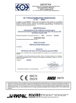
PlasmaPart Limited Instructions © 2012
USER MANUAL AND INFORMATION
MMA 200A
INVERTER WELDER
PlasmaPart Limited Instructions © 2012
Thank you for purchasing the PlasmaPart 200A MMA inverter
welder.
We have included this information pack as a reference document for all users; it is intended to
provide information relating to all areas of welding from health and safety to operational tips. We
strongly advise you to keep this document with the machine.
It is important you familiarise yourself with the information within this guide, both for your safety
and ease of operation of the unit.
Important Health and Safety Information
This unit in common with all arc welders uses a combination of low voltage and high current to
generate the high temperatures required to melt metals.
A welder can cause injury or death if used incorrectly.
There are several hazards associated with welding:
Heat
The arc created when welding is at around 5000 oC this presents a serious hazard if the arc beam
were to come in contact with you, as well as this the molten metal produced in the process can
also cause damage or injury to you if your feet or other parts of your body are not adequately
protected.
Welding should not be carried out within close proximity to any flammable substances or materials.
Electricity
When set to 100A welding current or below the machine can be used safely from a standard 13A
supply with an appropriate 13 Amp fuse fitted. For welding requirements above this amperage it is
recommended that the machine is connected to a 16 Amp supply.
If in doubt please contact a qualified electrician for advice.
Visible and Ultra Violet Light
The visible light generated by the arc process is very intense as with most arc welding operations
this can cause serious eye damage if the eyes are not protected during the welding operation. If
the eyes become sore or irritated it would be advisable to seek professional help and increase the
shading level.
As with most arc welding processes skin should be protected from exposure to the ultra violet light
emitted during the welding process.
Specification
© PlasmaPart Limited 2012 no part of these instructions may be reproduced without prior written consent
from PlasmaPart Limited
1
PlasmaPart Limited Instructions © 2012
Supply Voltage
1-ph AC 220±15% V
Supply Frequency
50~60 Hz
Power requirement (at 200A)
4.8 KVA (Max)
Rated input current (at 200A)
22 A (Max)
No-load voltage
90 V
Output current range
20-200 A
Output voltage range
20-40 V
Duty cycle @ 185 Amps Output
100%
Efficiency
95%
Cos φ (η)
0.93
Instruction Notes
1. Operating environment
1.1 The machine can be operated in harsh weather conditions at temperatures of
between -10 and +40 Degrees Centigrade and a Relative Humidity of 80%.
1.2 Do not place the machine in direct sunlight or operate it in the rain.
1.3 Keep the machine dry and avoid any contact with water.
1.4 Do not use the machine in a dusty atmosphere or one containing a corrosive or explosive
gas.
1.5 If the machine will not be used for a long period of time it should be returned to its original
packing box and stored in a dry environment.
1.6 The machine has an internal fan to cool the high power electronics and the entry and exit
ventilators must not be obstructed. Ensure there is sufficient space in front and behind the
machine for the forced air to circulate.
1.7 Ensure the power cable is connected to a supply which has the correct voltage and
current rating. The machine has a built in electronic control to adjust for different
mains voltage over a limited range. There is a label on the back of the machine
indicating the machine setting. Units supplied to the UK will be set for 220Vac
(190-255Vac) which is suitable for single phase supplies.
The machine will be seriously damaged if it is connected to a 415V Three Phase
supply.
1.8 Always stand the machine on a level surface to prevent the unit overturning.
© PlasmaPart Limited 2012 no part of these instructions may be reproduced without prior written consent
from PlasmaPart Limited
2
PlasmaPart Limited Instructions © 2012
2. OPERATING SAFETY
2.1 Ensure the working area is adequately ventilated and clear of all flammable materials.
2.2 The electrode is energised as soon as the mains power is turned on; there is no
welding current on / off switch.
2.3 Always turn the machine power off when the welding operation is completed.
2.4 When using the machine on site or outside ensure the grounding terminal on the back
of the machine is connected to a safety earth. This will prevent any leakage current
from the welding circuit causing an electric shock to the operator. A cable with a cross
sectional area of 6mm2 is suitable for this purpose. The electrode holder and work
clamp are not directly connected to the mains earth inside the unit although the unit
case is earthed to the mains cable protective conductor (earth wire)
2.5 Do not weld any containers or pipes which have held or contain gaseous or liquid fuels
or combustible substances.
2.6 Do not weld any containers or pipes which may be under pressure
2.7 Always wear eye protection. This is to protect your eyes from both the arc and also
sparks which are produced during the welding operation. A Minimum of shade 8 for
lower currents and shade 10 for higher currents is required for the machine. An autodarkening helmet with adjustable shades is strongly recommended.
2.8 Always wear suitable fire resistant protective clothing and boots to protect you from
heat and UV radiation burns. Clothing must be free from grease and oil contamination.
2.9 Always keep children and pets away from the work area and ensure anyone present is
wearing suitable eye protection before striking an arc..
2.10
Always turn the machine power off and remove the plug before servicing or
changing the cutting head components.
3. Setting up the machine
3.1 Ensure the front panel power switch is set to OFF and connect the mains cable to a
suitable high current supply. The machine if fitted with a 16A plug which must be used if
welding at 200A, it can be used on a domestic 13A supply for welding currents up to
100A. The OC light will come on and the unit will ‘lock out’ if the mains supply at the unit
drops below the lower 10% voltage limit when the arc is struck. This is due to an internal
monitoring function inside the unit to prevent damage to the electronic circuits. A
‘standard’ 13A extension cable is not suitable for use with the unit; always use a 16A
Caravan type extension.
3.2 Connect the positive terminal of the welder (right hand side) to the work clamp and
connect this to the welding bench or parent material to be welded.
3.3 Connect the electrode holder to the negative terminal (left hand side) of the machine the
welding current is maintained at the value set by the control on the front panel. The
machine cannot be overloaded; the machine has a built in electronic control circuit which
ensures the current flowing remains at the value set by the control knob almost
irrespective of the arc length.
3.4 This is the configuration for welding thin materials. The electrode and material clamp front
© PlasmaPart Limited 2012 no part of these instructions may be reproduced without prior written consent
from PlasmaPart Limited
3
PlasmaPart Limited Instructions © 2012
panel connections should be reversed for thicker materials.
3.5 The machine is now ready to weld.
3.6 Observe the machines duty cycle, which is 100% at 155A. If machine gets too hot a
monitoring circuit will automatically stop the machine working until the unit has reached a
safe level to continue. This is indicated by the OC light illuminating on the front panel and
the arc will not strike. The fan will continue to operate even if the machine is switched off
at the front panel. It is necessary to turn the machine power switch off and on again to
reset the monitoring circuit.
3.7 The welding current is maintained at the value set by the control on the front panel. The
machine cannot be overloaded; the machine has a built in electronic control circuit which
ensures the current flowing remains at the value set by the control knob.
3.8 The machine is now ready to weld.
4. Welding Operation
4.1
Before you start to weld, ensure that you have all the required equipment and
accessories. Listed below are some additional welding rules that should be followed.
Clear the welding area of all debris and clutter.
Do not use gloves or clothing that contains oil or grease.
Use a face screen to protect your eyes from light, heat and sparks.
Check that all wiring and cables are installed properly and are in good condition.
Follow all manufacturers’ directions on operating the welding machine.
Use a protective screen to protect others in the welding area from FLASH burns.
Always keep fire-fighting equipment available.
Clean rust, scale, paint, or dirt from the joints that are to be welded.
ELECTRODES
In general, all electrodes are classified into five main groups:
Mild steel
High-carbon steel
Special alloy steel
Cast iron
Nonferrous
The widest range of arc welding is done with electrodes in the mild steel group.
Electrodes are manufactured for use in specific positions and for many different types of
metal. They also are specially designed to use with ac or dc welding machines. Some
manufacturer’s electrodes work identically on either ac or dc, while others are best suited
for flat-position welding.
© PlasmaPart Limited 2012 no part of these instructions may be reproduced without prior written consent
from PlasmaPart Limited
4
PlasmaPart Limited Instructions © 2012
Another type are made primarily for vertical and overhead welding, and some can be used
in any position.
Electrode selection depends on many variables although for most mild steel operations
type E6013 are generally used.
Types of Electrodes
Electrodes are classified as either bare or shielded.
The original bare electrodes were exactly as their name implied, uncoated.
The shielded electrode has a heavy coating of several chemicals, such as cellulose, lowhydrogen sodium, or iron powder.
Each of the chemicals in the coating serves a particular function in the welding process. In
general, their main purposes are to induce easier arc starting, stabilize the arc, improve
weld appearance and penetration, reduce spatter, and protect the molten metal from
oxidation or contamination by the surrounding atmosphere.
As molten metal is deposited in the welding process, it attracts oxygen and nitrogen.
Since the arc stream takes place in the atmosphere, oxidation occurs while the metal
passes from the electrode to the work. When this happens, the strength and ductility of
the weld is reduced as well as the resistance to corrosion. The coating on the electrode
prevents the oxidation process from taking place.
The burning residue of the coating forms a slag over the deposited metal that slows down
the cooling rate and produces a more ductile weld. Some coatings include powdered iron
that is converted to steel by the intense heat of the arc as it flows into the weld deposit.
Select the correct welding rod for the material being welded and fit this to the electrode
holder. As a general rule the welding rod should be no thicker than the material being
joined.
5. Maintenance
5.1 Before use
Check the mains power wire for damage. Repair or replace any damaged items before
use.
5.2 Check the work clamp connector and electrode holder cables for damage. Repair or
replace as necessary. Ensure these are tight to their respective connections on the
unit.
5.3 Connect the earth stud on the back of the machine to the welding bench.
5.4 After use
Allow welding electrode to cool before removal and storage.
Disconnect the machine from the mains power supply.
Check all cables for damage and stow them in a safe place to avoid trip hazards.
This information should be considered important and you must understand it before
using the machine for your own and others safety. If there is something you don’t
understand please contact PlasmaPart Limited for clarification. We are here to help!
© PlasmaPart Limited 2012 no part of these instructions may be reproduced without prior written consent
from PlasmaPart Limited
5
PlasmaPart Limited Instructions © 2012
Declaration of Conformity
The undersigned company - PlasmaPart Ltd.
Unit 7, Waldron Court, Prince William Road, Loughborough, Leicestershire. LE11
5GD declares
that the product identified and described on this page
has been tested by their supplier and complies with standard EN 60974-7
in accordance with the requirements of directive
EEC 73/23 Low Voltage Directive
Certificate valid until 20.11.14
Portable Appliance Testing
This equipment is tested in accordance with the IEE Code of Practice - 3rd Edition Inspection and Testing of Electrical Equipment - by a person holding recoginised
qualifications using calibrated test equipment as part of PlasmaPart Ltd. PreDespatch QA procedures.
© PlasmaPart Limited 2012 no part of these instructions may be reproduced without prior written consent
from PlasmaPart Limited
6