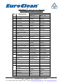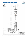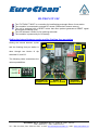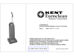
1
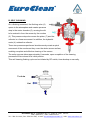
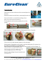
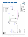
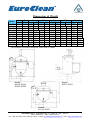
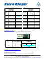
® OdisMatic Hydraulic Filter Series 851 Operator's Manual Models 85107 (¾") 85101 (1") 85115 (1½”) 85102 (2”) 85103 (3") 85104 (4") 85106 (6") 85108 (8") EuroClean s.r.o. Podbabská 81 /17, Praha 6 , PSČ: 160 00 IČO: 26141477, DIČ: CZ26141477 Tel.: 224 811 900, Fax: 224 810 597, e-mail: [email protected], web: www.euroclean.cz Content 1. Technical Specifications. 2. Materials. 3. Construction. 4. Operation Principle. 5. Installation. 6. First Commissioning and Routine Setup. 7. Start - Up 8. Manual Flushing Procedures. 9. Shut Down & Drainage Procedure. 10. Maintenance. 11. Parts list. 12. Parts breakdown 13. Control Diagram AC/ DC 14. Head Loss/ Flow Rate Diagram 15. Dimensions & Weight ODIS takes all possible precautions in packing each equipment item to prevent damage during shipment. Carefully inspect each item, and if damage occurred, please report ODIS immediately. EuroClean s.r.o. Podbabská 81 /17, Praha 6 , PSČ: 160 00 IČO: 26141477, DIČ: CZ26141477 Tel.: 224 811 900, Fax: 224 810 597, e-mail: [email protected], web: www.euroclean.cz TECHNICAL SPECIFICATION General Data Min. Working Pressure Max. Working Pressure 1 - 2 bar 15 - 30 psi 10 bar 150 psi For other working pressure consult ODIS representative. SCREEN AREA AND RECOMMENDED FLOW RATES MODEL 85107 85101 85115 85102 85103 85104 85106 85108 Inlet/Outlet diameter inch ¾" 1" 1½" 2" 3" 4" 6" 8" Max. Flow rate gpm m3/h 4 7 15 25 40 80 150 300 18 31 66 110 170 350 660 1300 Flushing* Flow rate gpm m3/h 2-3 2-3 4-5 4-5 4-5 4-5 8-10 12-14 9-13 9-13 17-22 17-22 17-22 17-22 35-44 53-62 Screen Area Sintered P.V.C. Housing cm2 Inch2 cm2 --------------600 600 1100 1100 4500 6200 --------------100 100 170 170 700 960 270 270 450 450 800 800 2900 4000 Inch2 42 42 70 70 130 130 450 620 Duration of flushing for ¾" and 1" models: 6-8 seconds. Duration of flushing for 1½", 2", 3" and 4" models: 8-12 seconds. Duration of flushing for 6", 8" models: 14-16 seconds. The max. flow rate refers to screens over 200 microns/less than 80 mesh For a finer filtration degree consults our representative. SCREEN GRADES* Mesh 400 300 200 150 120 100 80 50 30 Micron 30 50 80 100 120 150 200 300 400 * Other screens are available. EuroClean s.r.o. Podbabská 81 /17, Praha 6 , PSČ: 160 00 IČO: 26141477, DIČ: CZ26141477 Tel.: 224 811 900, Fax: 224 810 597, e-mail: [email protected], web: www.euroclean.cz MATERIAL Filter housing: Carbon Steel, electrostatic powder coating Optional: Stainless Steel. Filtration Screens: Standard: Weave wire mesh - P.V.C supported. Optional: Sintered multi-layer screen. Gaskets: Natural Rubber Optional: other material CONSTRUCTION The standard housing of the filter is made of carbon steel with a 100 micron protective coating of extra durable polyester, applied electrostatically and oven cured on a zincphosphate layer, for maximal anti-corrosion protection both internally and externally. The unique design of the flushing chamber enables easy maintenance. Access to the internal parts of the filter is through the removable bolted cover. All immersed parts are made of either plastic materials or non-corrosive metals to ensure many years of trouble free operation. Optional materials for special applications are available. Please contact ODIS representative. On top of the filter a hydraulic piston is mounted. The piston performs a longitudinal movement of the collector assembly with the suction nozzles, in order to clean the screen on all its length. Simultaneously the hydraulic motor rotates the collector assembly with the suction nozzles to clean the screen on its entire perimeter. The two motions guarantee that the suction nozzles will cover the whole screen surface and the cleaning process will be effective. EuroClean s.r.o. Podbabská 81 /17, Praha 6 , PSČ: 160 00 IČO: 26141477, DIČ: CZ26141477 Tel.: 224 811 900, Fax: 224 810 597, e-mail: [email protected], web: www.euroclean.cz 1. Screen 2. Collector 3. Suction nozzle 4. Hydraulic Motor 5. Flushing Chamber 6. Flushing Valve 7. Piston OPERATING PRINCIPLES A. NORMAL FLOW PATTERN Raw water enters the filter through the inlet port, passing through the fine screen (1) and out to the outlet port. The sediments stopped on the screen (1) create a "cake" of sediment. This "cake" improves filtration efficiency as it performs a finer filtration. The sediments accumulated on the screen, create a differential pressure across the screen. The differential pressure rises until the predetermined value is reached [normally 0.5 bar (7.5 psi)]. A pressure switch gauge will activate the self cleaning process. A timer backup guarantees that the time passed from the last self cleaning process will not be longer than the preset value determined by the user. EuroClean s.r.o. Podbabská 81 /17, Praha 6 , PSČ: 160 00 IČO: 26141477, DIČ: CZ26141477 Tel.: 224 811 900, Fax: 224 810 597, e-mail: [email protected], web: www.euroclean.cz B. SELF CLEANING On a flushing command, the flushing valve (6) opens to the atmosphere and creates pressure drop in the motor chamber (5), causing the dirt to be sucked in from the screen by the nozzles (3). This pressure drop also moves the piston (7) and the collector in a linear movement. In addition, the hydraulic motor (4) rotates the collector. These two processes performed simultaneously create a spiral movement of the nozzles so they cover the whole screen surface, enabling complete and effective cleaning of the screen. The entire process takes approximately 8 seconds, upon completion of the cleaning process the filter returns to its initial position. This self cleaning flushing cycle can be initiated by DP switch, timer backup or manually. To drain Out In EuroClean s.r.o. Podbabská 81 /17, Praha 6 , PSČ: 160 00 IČO: 26141477, DIČ: CZ26141477 Tel.: 224 811 900, Fax: 224 810 597, e-mail: [email protected], web: www.euroclean.cz INSTALLATION • Install the filter only in vertical position. • A pressure relief valve must be installed before the filtering installation if the pressure is not controlled effectively. • Prevent back-pressure or reverse flow - install a mechanical non-return valve on the filter outlets. • Ensure there is enough space around the filter for easy maintenance. • Inlet and outlet are marked by an arrow. • Connect a drain pipe to the flushing valve; pipe diameter should fit the valve diameter to prevent pressure loss. • Check for leaks. NOTE: Install isolation valves at inlet & outlet. These valves will enable to service the filter whenever needed, and in addition the outlet valve can be used to adjust the flow rate if needed. FIRST COMMISSIONING AND ROUTINE START - UP 1. Check that the line pressure will always be at least 1 bar (15 psi) at the filter inlet during the flushing cycle. 2. Check that there are no upstream pipeline restrictions. 3. Check that the filter is mounted properly, as indicated by the arrows. 4. Check that the flushing valve is mounted properly. 5. Check that the tubing connections are completed. 6. Check that the flushing valve drain pipe is connected. 7. Check that the upstream and downstream isolation valves are closed. 8. Install batteries in the controller when using a DC controller. Or connect the controller to power source when using an AC controller. NOTE: The differential pressure switch and timer have been preset to the proper settings. Do not adjust prior to start-up. EuroClean s.r.o. Podbabská 81 /17, Praha 6 , PSČ: 160 00 IČO: 26141477, DIČ: CZ26141477 Tel.: 224 811 900, Fax: 224 810 597, e-mail: [email protected], web: www.euroclean.cz START - UP 1. Slowly open the inlet valve to the filter allowing the filter to pressurize. 2. Check for any leaks and eliminate. 3. Disconnect the control tube from the hydraulic piston and bleed it until all of the air is displaced by water. Reconnect the control tube. 4. Slowly open the outlet valve of the filter (if installed). 5. Initiate a manual flushing; observe the inlet and motor chamber pressures (use three way valve and manometer mounted on the control box). The motor chamber pressure should be between 0.8-1.5 bar below inlet pressure during the flushing cycle. Minimum inlet pressure during flushing cycle should be: − 1 bar (15 psi) for models ¾", 1", 1½", 2", 3" and 4". − 2 bar (30 psi) for models 6" and 8". 6. Observe the differential pressure's build up across the filter. It is recommended to observe at least one full cycle to ensure that the system is operating properly. MANUAL FLUSHING PROCEDURES Periodically, it may be necessary to activate a manual flushing cycle of the filter. Some typical reasons are: -Routine inspection of proper filter operation. -Emergency cleaning of the filter. -Troubleshooting /start up. The manual flushing is activated by depressing the "manual" button located inside the controller box in a DC model, and on the controller box in AC model. EuroClean s.r.o. Podbabská 81 /17, Praha 6 , PSČ: 160 00 IČO: 26141477, DIČ: CZ26141477 Tel.: 224 811 900, Fax: 224 810 597, e-mail: [email protected], web: www.euroclean.cz SHUT-DOWN & DRAINING PROCEDURES SHUT DOWN PROCEDURE 1. Close the isolating valve on the outlet of the filter (if equipped). 2. Initiate a manual flushing as described in section 5. 3. Close the isolating valve at the inlet of the filter 4. Initiate an additional manual flushing cycle to relieve the pressure from the filter. DRAINAGE PROCEDURE Prior to accessing the filter internal parts, it is necessary to drain the filter. Note that uncontrolled emptying of the filter may result an excessive water spillage in the area around the filter. MAINTENANCE * Repair damage to the protective coating of the filter immediately. * Prior to applying the protective paint, clean the damaged spot thoroughly with a wire brush. * Every three (3) months lubricate the piston with lubrication grease “DOW CORNING 4” or EQUAL. Piston lubrication is needed for ¾", 1", 3”, 4", 6" and 8” filters only. Warning: for lubrication use only “DOW CORNING 4” or EQUAL. Using other lubrication grease will damage piston’s rubber parts. EuroClean s.r.o. Podbabská 81 /17, Praha 6 , PSČ: 160 00 IČO: 26141477, DIČ: CZ26141477 Tel.: 224 811 900, Fax: 224 810 597, e-mail: [email protected], web: www.euroclean.cz Piston lubrication Depressurize the filter and disconnect the command pipes from the piston. Dismantle the piston from the filter by unscrewing the piston out. Screw out the bolts (1), and pull the front flange (2) out. Note: do not screw out the rear bolts (3) Pull the piston bar with the whole assembly (4) out of the cylinder. 1 3 2 4 Apply a thin layer of lubrication grease to following parts: (5), (6), (7) and (8). 5 12 6 7 8 9 Fill the inner slot (9) with lubrication grease up to the slot edges. Slide the piston (4) assembly into the cylinder; verify that leading strip (12) is placed in its slot. Slide the front flange (2) on the piston bar (4). Align the screw holes on the cylinder (10) with the screw threads on the front flange (11). Screw the bolts (1), and gently tighten them. Install the piston on the filter, and connect the command pipes back to the “TEE” fitting. 11 10 Check for water leakage during next operation and flushing process. EuroClean s.r.o. Podbabská 81 /17, Praha 6 , PSČ: 160 00 IČO: 26141477, DIČ: CZ26141477 Tel.: 224 811 900, Fax: 224 810 597, e-mail: [email protected], web: www.euroclean.cz OdisMatic® 851 (1½"- 8") Part List (refer to drawing D-C851-001-01 issue 4) MODELS No. DESCRIPTION 85115 (1½") 85102 (2") 85103 (3") 85104 (4") 85106 (6") 85108 (8") 1 Filter body A85115 A85102 A85103 A85104 A85106 A85108 2 Cover gasket ER02004 ER02004 ER02004 ER02004 ER10033 ER10033 E8510204 E8510204 E8510404 E8510404 E8510604 E8510804 E8510209 E8510209 E8510409 E8510409 E8510609 E8510817 E8510206 E8510206 E8510406 E8510406 E8510606 E8510806 E8510205 E8510205 E8510405 E8510405 E8510616 E8510816 3 3-A 3/1 3/1-A Fine screen Ass. – ( P.V.C) Fine screen Sintered – Ass. Fine screen – PVC body Fine screen Sintered 3/2 Seal ER02025 ER02025 ER02025 ER02025 E8628000 E8628000 3/3 Upper Bearing ER02075 ER02075 ER02075 ER02075 ER03077 ER03077 ER02093 ER02093 ER02093 ER02093 ER10016 ER10016 E8510202 E8510202 E8510402 E8510402 E8510602 E8510815 E8510203 E8510203 E8510403 E8510403 E8510613 E8510813 E8510208 E8510208 E8510614 E8510614 3/4 4 4/1 Fine screen handle Dirt collector – Assembly Dirt collector body 4/2 Hydraulic motor E8510208 E8510208 4/3 Hydraulic motor locking bolt E8510207 E8510207 4/4 Suction nozzle ER8510402 ER8510402 ER8510402 ER8510402 ER8510602 ER8510602 5 Flushing chamber E8510211 E8510211 E8510411 E8510411 ----------------- ----------------- 6 Flushing valve 7 Hydraulic piston E8510212 E8510212 --------------- ----------------- ----------------- ----------------- 7A Hydraulic piston ---------------- ----------------- E8510412 E8510412 E8510612 E8510612 8 Cover E8510201 E8510201 E8510401 E8510401 E8510601 E8510601 9 Bolt 10 Bearing base E8510413 E8510413 E8510413 E8510413 E8510618 E8510618 11 Lower Bearing E8510414 E8510414 E8510414 E8510414 E8510619 E8510619 E8510407ER NB20501002T NB20501501T L2912102035U L2912102030U AC Controller N5301101 DC Controller N53102FT01-DP 12 13 14 15 15A Pressure gauge 3 way valve selector Differential pressure switch (electronic) Differential Pressure Switch N6111025 N6111025 N6111025 N6111025 N6111025 N6111025 PM202500 PM202500 PM202500 PM202500 PM202500 PM202500 N.A N.A N.A N.A N.A N.A N6040 N6040 N6040 N6040 N6040 N6040 EuroClean s.r.o. Podbabská 81 /17, Praha 6 , PSČ: 160 00 IČO: 26141477, DIČ: CZ26141477 Tel.: 224 811 900, Fax: 224 810 597, e-mail: [email protected], web: www.euroclean.cz No. DESCRIPTION 85115 (1½") 85102 (2") MODELS 85104 85103 (4") (3") Solenoid valve AC 16 17 18 Solenoid DC latch (2 wires) Solenoid DC latch (3 wires) Pressure control box Pressure control box side cover 85106 (6") 85108 (8") N512009-8W NA NA NA NA NA NA N512006 N512006 N512006 N512006 N512006 N512006 Y8510201 Y8510201 Y8510201 Y8510201 Y8510201 Y8510201 Y8510203 Y8510203 Y8510203 Y8510203 Y8510203 Y8510203 EuroClean s.r.o. Podbabská 81 /17, Praha 6 , PSČ: 160 00 IČO: 26141477, DIČ: CZ26141477 Tel.: 224 811 900, Fax: 224 810 597, e-mail: [email protected], web: www.euroclean.cz OdisMatic ® 851 (1½"- 8") Parts breakdown EuroClean s.r.o. Podbabská 81 /17, Praha 6 , PSČ: 160 00 IČO: 26141477, DIČ: CZ26141477 Tel.: 224 811 900, Fax: 224 810 597, e-mail: [email protected], web: www.euroclean.cz OdisMatic® - 851 (¾"- 1") Part List (refer to drawing D-C859-001-02 issue 1) DESCRIPTION NO MODEL 85107 (¾") 85101 (1") 1 Filter body A85107M A85101M 2 Inner gasket E000820 E000820 3 Fine screen Assembly E8510104 E8510104 3/1 Fine screen E8511006 E8511006 3/2 Fine screen handle ER8511020 ER8511020 3/3 Lower Bearing ER02075 ER02075 4 Dirt collector – Assembly E8511002 E8511002 4/1 Dirt collector body E8511003 E8511003 4/2 Hydraulic motor E8511008 E8511008 4/3 Hydraulic motor locking bolt E8511004 E8511004 4/4 Suction nozzle ER8511002 ER8511002 5 Separating Disc ( Upper Bearing base) E8511013 E8511013 6 Upper Bearing E8511014 E8511014 7 Flushing chamber E8511011 E8511011 8 Cover gasket E000920 E000920 9 Cover E8511001 E8511001 10 Reducer ¾" x 1"-BSP H0630710 H0630710 11 Elbow 90 x 1"- BSP H91010BSP H91010BSP 12 Flushing valve NB20501002T NB20501002T 13 Hydraulic piston E8511012 E8511012 14 Bolt L2912102060U L2912102060U AC Controller N5301T2AC-11/22 N5301T2AC-11/22 DC Controller N53102FT01-DP N53102FT01-DP 16 Pressure control box side cover Y8510203 Y8510203 17 Pressure control box Y8510201 Y8510201 18 3 way valve selector PM202500 PM202500 19 Pressure gauge N6111025 N6111025 Solenoid valve – AC N512009-8W N512009-8W NA NA N512006 N512006 N.A N.A 15 20 21 Solenoid DC latch (2 wires) Solenoid DC latch (3 wires) Differential pressure switch (electronic) 21A Differential Pressure Switch N6040 N6040 22 Outlet Valve ¾" x 1"-BSP N700010 N700010 EuroClean s.r.o. Podbabská 81 /17, Praha 6 , PSČ: 160 00 IČO: 26141477, DIČ: CZ26141477 Tel.: 224 811 900, Fax: 224 810 597, e-mail: [email protected], web: www.euroclean.cz EuroClean s.r.o. Podbabská 81 /17, Praha 6 , PSČ: 160 00 IČO: 26141477, DIČ: CZ26141477 Tel.: 224 811 900, Fax: 224 810 597, e-mail: [email protected], web: www.euroclean.cz EuroClean s.r.o. Podbabská 81 /17, Praha 6 , PSČ: 160 00 IČO: 26141477, DIČ: CZ26141477 Tel.: 224 811 900, Fax: 224 810 597, e-mail: [email protected], web: www.euroclean.cz EuroClean s.r.o. Podbabská 81 /17, Praha 6 , PSČ: 160 00 IČO: 26141477, DIČ: CZ26141477 Tel.: 224 811 900, Fax: 224 810 597, e-mail: [email protected], web: www.euroclean.cz EuroClean s.r.o. Podbabská 81 /17, Praha 6 , PSČ: 160 00 IČO: 26141477, DIČ: CZ26141477 Tel.: 224 811 900, Fax: 224 810 597, e-mail: [email protected], web: www.euroclean.cz EuroClean s.r.o. Podbabská 81 /17, Praha 6 , PSČ: 160 00 IČO: 26141477, DIČ: CZ26141477 Tel.: 224 811 900, Fax: 224 810 597, e-mail: [email protected], web: www.euroclean.cz Head Loss / Flow Rate EuroClean s.r.o. Podbabská 81 /17, Praha 6 , PSČ: 160 00 IČO: 26141477, DIČ: CZ26141477 Tel.: 224 811 900, Fax: 224 810 597, e-mail: [email protected], web: www.euroclean.cz Dimensions & Weight H* E* A* D B inch inch mm inch mm inch mm inch 85107M ¾ 6 150 5.9 410 16 500 18 500 18 16 150 5.9 410 6 1 85101M 85115M 1½ 10 188 7.4 540 21 500 18 540 21 21 230 9.1 540 10 1½ 85115F 85102M 2 10 196 7.7 540 21 500 18 540 21 21 230 9.1 540 10 2 85102F 85103M 3 10 260 10.2 540 21 720 28 740 29 21 540 11 280 10 3 85103F 85104F 4 10 280 11 540 21 740 29 24 1310 52 540 21.2 600 6 12 85106F 85108F 8 12 700 27.6 600 24 1530 60 * For Victaulic connection decrease 5 mm from F model. Model Models 85103, 85104, 85106, 85108 T* mm inch 155 6.1 155 6.1 175 6.9 220 8.7 185 7.3 220 8.7 195 7.7 220 8.7 220 8.7 320 12.6 320 12.6 Weight lbs Kg 11 24 24 11 25 55 57 26 27 60 62 28 40 88 90 41 42 92 65 143 78 172 Models 85107, 85101 Models 85115, 85102 EuroClean s.r.o. Podbabská 81 /17, Praha 6 , PSČ: 160 00 IČO: 26141477, DIČ: CZ26141477 Tel.: 224 811 900, Fax: 224 810 597, e-mail: [email protected], web: www.euroclean.cz OdisMatic ( Electric or Hydraulic Filter) WARRANTY 1.During a period of Four (4) years (“the Warranty Period”) which commences on the delivery date (F.O.B. – Israeli Port) - or up to two (2) years commences on the installation date, but in any case not more than the warranty period mentioned above, and subject to the provisions of this warranty, Odis shall remedy in the manner described below any defect in the equipment which results directly from Odis faulty materials or workmanship. 2.During the Warranty Period, Odis shall repair or replace any part of the Equipment found to be defective in manufacture, or, at its option, refund the portion of the purchase price attributable thereto. Such repair, replacement or refund is purchaser’s sole and exclusive remedy for defective Equipment. Without derogating from the generality of the foregoing, Odis liability shall be limited to the cost of materials and labor required for the repair or replacement or refund of the defective part. 3.Purchaser must notify Odis in writing of the claimed defect, including a detailed description of the defect. Such notice shall be submitted to Odis promptly and without any delay after the discovery of the defect. 4.Purchaser shall not attempt any repair or replacement of the Equipment other than in cases of emergency. In no case shall Odis be liable for the cost of such repairs or replacement carried out by the Purchaser. 5.Odis shall have no responsibility for defects in the Equipment to the extent caused by use other than as stated in Odis’ Operating Manual, misuse, abuse, or installation, maintenance, operation or repairs by the purchaser or by persons not under the supervision of Odis. 6.When a defect in a part of the Equipment has been remedied, the repaired or replaced parts shall be deemed to be part of the Equipment and Odis shall be liable for defects therein until the end of the Warranty Period. Any defective part which is replaced by Odis shall thereupon become Odis’ sole property. 7.Odis liability to defects in components of the Equipment which are not manufactured by Odis (including, but not limited to, computers, electrical boards, gaskets, gauges, valves, flow and turbidity meters) is limited to defects which results directly from faulty materials or workmanship, that are discovered within a period of 1 (one) year from the installation date, but in any case not more than the warranty period mentioned above. 8.The foregoing warranty is in lieu of all other warranties, expressed or implied, including, but not limited to any implied warranties of merchantability or fitness for a particular purpose. 9.In no event shall Odis be liable for any other damages whatsoever (including, without limitation damages for loss of business profit, business interruption, or other pecuniary loss) arising out of the use of or inability to use the equipment, even if Odis has been advised of the possibility of such damages . 10. In any case, Odis entire liability under any provision of this warranty shall be limited to the amount actually paid by the purchaser for the equipment . EuroClean s.r.o. Podbabská 81 /17, Praha 6 , PSČ: 160 00 IČO: 26141477, DIČ: CZ26141477 Tel.: 224 811 900, Fax: 224 810 597, e-mail: [email protected], web: www.euroclean.cz FILTRON 1/2/3 (AC) The “FILTRON 1/2/3+DP” is a controller for flushing automatic filters of one, two or three stations. The controller is connected to external DP sensor (Differential Pressure sensor). The unit is equipped with a RESET button that when pushed generates a RESET signal and triggers a flushing cycle. The unit is equipped with two LED indicators, the green one indicates that the unit is energized and the red one indicates the operation statuses. Can be powered either by 110v AC or 220V AC. Activates solenoids of 24V AC. 110V or 220V powering The following pictures show the difference in the wiring in case of powering by 110v or powering by 220V AC. Setting the interval between cycles and the flushing time per station Setting the interval between cycles and the flushing time per station is done through two blocks of dip switches S1, and S2. S3 S S1 The following table summarizes the various possibilities: 1-ON 0-OFF SOLENOID CONNECTIONS EuroClean s.r.o. Podbabská 81 /17, Praha 6 , PSČ: 160 00 IČO: 26141477, DIČ: CZ26141477 Tel.: 224 811 900, Fax: 224 810 597, e-mail: [email protected], web: www.euroclean.cz 1 – ON 0 - OFF INTERVAL FLUSHING BETWEEN CYCLES TIME PER STATION S1 meaning 1 – ON 0 - OFF 1 2 3 4 S2 meaning 1 2 3 4 01 0 0 0 0 DP only 01 0 0 0 0 5 sec. 02 1 0 0 0 5 min. 02 1 0 0 0 8 sec. 03 0 1 0 0 10 min. 03 0 1 0 0 10 sec. 05 0 0 1 0 20 min. 04 1 1 0 0 12 sec. 06 1 0 1 0 30 min. 05 0 0 1 0 16 sec. 07 0 1 1 0 45 min. 06 1 0 1 0 20 sec. 08 1 1 1 0 1 hour 07 0 1 1 0 25 sec. 09 0 0 0 1 2 hours 08 1 1 1 0 30 sec. 10 1 0 0 1 4 hours 09 0 0 0 1 45 sec. Summary of the beeping sound indications 1 beep every 15 sec- normal operation 2 beeps every 15 sec- endless looping problem detected NOTE: Push RESET button after fixing a problem or to initiate manual flushing. EuroClean s.r.o. Podbabská 81 /17, Praha 6 , PSČ: 160 00 IČO: 26141477, DIČ: CZ26141477 Tel.: 224 811 900, Fax: 224 810 597, e-mail: [email protected], web: www.euroclean.cz FILTRON FT1 DC The “FILTRON FT1&DP” is a controller for backflushing automatic filters of one station. The controller is connected to external DP sensor (Differential Pressure sensor). The unit is equipped with a RESET button that when pushed generates a RESET signal and triggers a flushing cycle. The unit activates 2 wired 12v DC latching solenoids. The controller is powered by 6v DC battery. Setting the interval between cycles and the flushing time per station Setting the interval between cycles S3 S1 and the flushing time per station is done through two blocks of dip switched S1, and S2. S2 The following table summarizes the various possibilities: 1-ON 0-OFF EXTERNAL DP CONNECTIONS RESET & MANUAL FLUSHING SOLENOID CONNECTIONS EuroClean s.r.o. Podbabská 81 /17, Praha 6 , PSČ: 160 00 IČO: 26141477, DIČ: CZ26141477 Tel.: 224 811 900, Fax: 224 810 597, e-mail: [email protected], web: www.euroclean.cz INTERVAL BETWEEN CYCLES 1 – ON FLUSHING TIME PER STATION S1 0 - OFF meaning 1 – ON S2 0 - OFF 1 2 3 4 meaning 1 2 3 4 01 0 0 0 0 DP only 01 0 0 0 0 5 sec. 02 1 0 0 0 5 min. 02 1 0 0 0 8 sec. 03 0 1 0 0 10 min. 03 0 1 0 0 10 sec. 05 0 0 1 0 20 min. 04 1 1 0 0 12 sec. 06 1 0 1 0 30 min. 05 0 0 1 0 16 sec. 07 0 1 1 0 45 min. 06 1 0 1 0 20 sec. 08 1 1 1 0 1 hour 07 0 1 1 0 25 sec. 09 0 0 0 1 2 hours 08 1 1 1 0 30 sec. 10 1 0 0 1 4 hours 09 0 0 0 1 45 sec. Setting S3 dip switch block Set the dip switch block S3 to "0 0 0 0" to disable the internal DP (not included) 1-ON 0-OFF Position No. S3 (1-ON ; 0-OFF) 1 2 3 4 00 0 0 0 0 Set-point meter bar psi The internal DP sensor is not active Summary of the beeping sound indications 1 beep every 15 sec- normal operation 3 beeps every 15 sec- low battery NOTE: Push RESET button after fixing a problem or to initiate manual flushing. EuroClean s.r.o. Podbabská 81 /17, Praha 6 , PSČ: 160 00 IČO: 26141477, DIČ: CZ26141477 Tel.: 224 811 900, Fax: 224 810 597, e-mail: [email protected], web: www.euroclean.cz EuroClean s.r.o. Podbabská 81 /17, Praha 6 , PSČ: 160 00 IČO: 26141477, DIČ: CZ26141477 Tel.: 224 811 900, Fax: 224 810 597, e-mail: [email protected], web: www.euroclean.cz