1
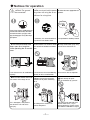
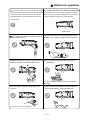
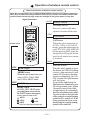
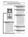
CLIMATE CONTROL
CLIMATE CONTROL
WALL SPLIT TYPE
66129902621
OWNER'S MANUAL
Models:
CCS-24HR4LW
Thank you for choosing this air conditioner
for correct operation, please read this owner's manual
carefully before operating the unit and keeps it carefully
for consultation.
CONTENTS
Operation and maintenance
■ ................................1
Notices for operation
Notices for use
■ ....................................4
Names and functions of each part
■ . ......................5
Operation of wireless remote control
■ .....................6
■ Clean
...................................9
and care
Troubleshooting
■ ...................................11
Installation service
■ ...............................14
Notices for installation
■ .........................16
Installation dimension diagram
Install indoor unit
■ .................................17
Install outdoor unit
■ .................................19
Check after installation and test operation
■ .................20
This symbol stands for the items
should be forbidden.
This symbol stands for the items
should be followed.
Thank you for choosing this air conditioner, please read this owner's
manual carefully before operating the unit and keep it carefully for consultation.
Operation and maintenance-Notices for operation
Please read the following carefully before operating.
WARNING
When having a burning smell
Don't operate the air conditioner
Never cut off or damage power
cables and control wires. If the power
or smoke, please turn off the power with wet hands.
cable and signal control wire were
supply and contact with the service
damaged,
change them by professional
center of CLIMATE CONTROL.
If the abnormity still exists, the unit Otherwise, it can cause an electric
may be damaged, and may cause shock or fire.
electric shock or fire.
Power must adopts the special
circuit to prevent fire.
Be sure to pull out the power
★ Never damage the electric wire
plug as the air conditioner not in use or use the electric wire, which is not
for a long time.
appointed.
Otherwise, it can cause an electric Otherwise, the accumulated dusts Otherwise, it will cause overheating
shock or fire.
that may cause overheating or fire. or fire.
The air conditioner should be
★ When cleaning, it is necessary
to stop driving and turn off the power operated with the voltage range
that is the rated voltage 10%,
supply.
the rated voltage is 220-240V~,
when the voltage is very low, the
compressor vibrates terribly and
Cut off power supply
that will damage the refrigerant
system; When the voltage is very
high, the electrical component
would be easily damaged.
Otherwise, it may cause electric
shock or damage.
1
The power supply must adopt
the special circuit that with air switch
protection and assure it has enough
capacity. The unit will be turned on
or off according to your requirement
automatically, please do not turn on
or turn off the unit frequently, otherwise disadvantage effect may be
caused to the unit.
Notices for operation
★ Earth:The
ground
★ Be sure to pull out the power ★ Select the most appropriate tembe connected!
plug when not using the air conditioner for a long time.
perature.
Keep room cooer than outside
about 5 ℃
If not, please ask the qualified personnel to install. Furthermore, don't connect each wire to the gas pipe, water
pipe, drainage pipe or any other improper places.
Otherwise, the accumulated dust It can preclude the electricity wasted.
may cause fire or electric shock.
★Don't leave windows and ★ Don't block the air intake or outlet ★ Keep combustible spray away
vents of both the outdoor and indoor from the units more than 1m.
doors open for a long time
while operating the air conditi- units.
oner.
It can decrease the air conditioning It can decrease the air conditioning
capacity or cause a malfunction.
capacity.
★Please note whether the install- ★ Don't step on the top of the
ed stand is firm enough or not.
outdoor unit or place something
on it.
If it is damaged, it may lead to
the fall of the unit and cause
the injury.
As falling off the outdoor unit
can be dangerous.
2
It can cause afire or explosion.
Don't attempt to repair
the air conditioner by yourself.
The wrong repair will lead to an
electric shock or fire, so you
should contact the service center
of CLIMATE CONTROL to repair.
Notices for operation
The power cords of this air conditioner adopt
X-type connection, please don't cut off or damage
the power cords and control cords. If they are
damaged, please ask the qualified personnel to
★ To adjust the airflow and direction appropriately.
At operating the louvers of air conditioner could be
adjusted by pressing the SWING button on wireless
remote control to change the airflow direction.
change them.
Guide louver
Don't insert your hands or stick into the air
intake or outlet vents.
★ Don't blow the wind to animals and plants
directly. It can cause a bad influence to them.
★ Splashing water on the air conditioner can ★ Don't place a space heater near the air
conditioner.
cause an electric shock and malfunction.
Or CO toxicosis may occur for imcomplete
burning.
★ Don't apply the cold wind to the body for a
★ Don't use the air conditioner for other purposes,
long time.
such as drying clothes, preserving foods, etc.
It can cause the health problems.
3
Notices for use
Working principle and special functions for cooling
Principle:
Air conditioner absorbs heat in the room and transmit to outdoor and discharged,
so that indoor ambient temperature decreased, its cooling capacity will increase
or decrease by outdoor ambient temperature.
Anti-freezing function
If the unit is running in COOL mode and in low termperature, there will be frost formed
on the heat exchanger, when indoor heat exchanger temperature decreased below 0℃,
the indoor unit microcomputer will stop compressor running and protect the unit.
Working principle and special functions for heating
Principle:
* Air conditioner absorbs heat in the room and transmit to outdoor and discharged,
will increase, its heating capacity will decrease by outdoor ambient temperature.
so that indoor ambient temperature increased, so room heating capacity.
* This heating air circulation system can enhance the indoor temperature
in a short while.
* If outdoor temperature got lower, please operate with the other heating ventilating
equipments.
Defrosting:
* When outdoor temperature is low but high humidity, after a long while running,
frost will form on outdoor unit, that will effect the heating effect, at this time,
the auto defrosting function will act, the heat running will stop for 8-10mins.
* During the auto defrosting, the fan motors of indoor unit and outdoor unit will stop.
* During the defrosting, the indoor indicator flashes, the outdoor unit may emit vapor.
This is due to the defrosting, it isn't malfunction.
* After defrosting finished,the heating will recover automatically.
Anti-freezing function:
In "HEAT" mode, if in the following status, the indoor heat exchanger haven't achieve
the certain temperature, that the indoor unit will not act, in order to prevent cool air blowing.
(Within 3mins)
1.Heating starts. 2.After Auto defrosting finished. 3.Heating under the low temperature.
★ The conditions of unit can't normally run
The following temperature range protection device may act, that may cause stop running.
Outdoor temp above
Outdoor temp above
24℃
"HEAT"
running
Outdoor temp below
-7℃
Indoor temp. above
27℃
"COOL"
running
43℃
Indoor temp. below
"DRY"
running
Indoor temp. below
18℃
21℃
Under the relative humidity above 80%( doors and windows opened) when cooling or dihumidifying for a long time, there will be dew drip off near the air vent.
4
Names and functions of each part
Indoor Unit
Air inlet
⑶
⑴
⑵
Air Outlet
Set Temp
Heating (This indicator
is black for singlecooling unit).
⑷
⑹
⑸
Wireless remote control
Cooling
Outdoor Unit
Air inlet
(1)
Front Panel
(2)
Guide louver
(3)
Receiving window
(4)
LED
(5)
Wall Pipe
(6)
Wrapping Tape
(7)
Indoor & outdoor
Board
cable
(8)
⑺
⑻
Air Outlet
5
Drainage pipe
Operation of wireless remote control
Name and function of wireless remote control
Note: Be sure that there are no obstructions between receiver and remote controoler;
Don't drop or throw the remote control; Don't let any liquid in the remote control and
put the remote control directly under the sunlight or any place where is very hot.
Signal transmitter
ON/OFF
ON/OFF button
ON/OFF button
Press it to turn on the unit,
repress it to turn off the unit.
FAN
FAN button
W hen the unit is turned on, in
AUTO, COOL, FAN, HEAT
modes, press this button can select AUTO FAN, LOW, MED, HIGH fan speed, in DRY mode, the
fan speed is LOW speed, the fan
speed in all modes have memory function.
Remote control
SWING
MODE
SWING button
SWING button
When the unit is turned on, press
this button, the SWING function
is active, when repressed, it will
turned off; When press this button twice continuously, the ON,
OFF of controller light function
will shift once.
If turn off the light button (At
light turned on, continuously press
the swing button twice within
1second to turn off the light;
At light turned off, continuously
press the swing button twice within
1second to turn on the light),that
all the symbols except the running
symbol will be turned off; If the
sleep operation has been set up,
that all symbols except the running
symbol will be turned off.
MODE button
MODE button
When the unit is turned on, can
select AUTO, COOL, DRY
and FAN or HEAT mode.
SLEEP
FAN button
SLEEP button
SLEEP button
In COOL, DRY, HEAT mode,
press this button once to turn on
the SLEEP button, when repress
it once more to turn it off.
AUTO
DRY
COOL
FAN
HEAT
(only for cooling and heating unit)
6
Operation of wireless remote control
Names and functions of wireless remote control
This wireless remote control is universal, and it could be used for many units, some buttons
of this control which are not available to this unit will not be described below.
TIMER OFF
TIMER OFF button
TIMER OFF button
Press this button once enter
into the TIMER OFF setting.
TEMP.
TEMP. Adjusting , the temp. in
In COOL, DRY,FAN or HEAT
modes, press these two buttons,
could set the temp., the setting
range is 16℃-30℃all modes
have the memory function.
Wireless remote control
TIMER ON
CLOCK
TEMP. Adjusting button
TIMER ON button
TIMER ON button
Press this button once, enter into
TIMER ON setting, the timer
indicator starts to flash, when press the H-UP button, the time of
timer on will be increased 1 minute,
when continuously press 1 second
or more, each ten minutes will be
increased 1 minute, in each 0.5
second, when press H-DOWN, the
time will be decreased 1 minute,
when continuously press 1 second
or above, in each 0.5 second, each
ten minutes will be decreased 1minute, and it runs at 12hour circulation.
CLOCK button
CLOCK button
Press this button once, the indicator
flashes, and enter into clock adjusting
state. In clock adjusting state, when
press H-UP once, the unit order of
minute will be increased 1, when
press 1 more seconds continuously,
e ch ten minutes will be increased
1 in each 0.5 second,.When press
H-DOWN once, the unit order of
minute will be decreased 1, when
press 1 more seconds continuously,
each ten minutes will be decreased
1 in each 0.5 second.When adjusting
has been finished,repress CLOCK
again to affirm.
RESET
RESET button
RESET button
Press this button once, the control
will reset.
CANCEL
CANCEL button
CANCEL button
Press this button once, to cancel
all timer setting.
7
Operation of wireless remote control
Guide for operation procedure-Optional operation
The general procedure:
1.After powered on, there is a warning tone sound by buzzer, all patterns displayer of indoor unit displayed,
a few seconds later, all the display will automatically turned off, except the POWER/ RUN light,
The POWER/RUN running light turns red, the unit is await.( NOTE: Each time when power on or receive
the signals from the wireless remote control, the buzzer will sound)
2.Press ON/ OFF button on the wireless remote control, POWER/ RUN indicator turns green, and display
the running mode and setting temp. etc, the unit starts to run.(NOTE: if set the SLEEP function or turn off
the light button, all the displays will be turned off except the POWER/ RUN indicator.
3.Press MODE, select the desirable running modes.
4.When press SWING button, the guide louver will swing automatically,when repressed the button, it will stop.
5.Press FAN button, set the fan speed.
6.When press Temp-UP/ Temp-DN the button, to set the desired temp.
The selected procedure:
7.Press SLEEP button, to set the sleep.
8.Press T-OFF/T-ON button, then press H-UP/H-DN button, to set the schedule time of turning on or turning off.
Note: When select the AUTO mode, the unit can choose the suitable running modes, automatically, and can obtain
the comfortable effect.
Change the batteries
The wireless remote control adopts two AAA alkaline dry cells.
1. Slide the cell cover downward to take out the worn cells, then change two new ones.( note to the correct polarity.)
2. Cover the cell cover.
NOTE:
Don't confuse the new and worn
or batteries of different types.
If the wireless remote control would
not be used for weeks, please take
out batteries to prevent liquid leakage
from damaging it.
When operating the wireless remote control,
it should be in its receiving range.
The wireless remote control should be
placed about 1m or more away from
the TV or any other electric appliances.
ACL
Insert two AAA batteries.
Cell cover
8
Clean and care
Caution
●
Turn power off and pull out the power plug before cleaning air conditioner, or it may cause electric shock.
●
Never sprinkle water on the indoor unit and the outdoor unit for cleaning because it can cause an electric shock.
●
Volatile liquid (e.g. thinner or gasoline) will damage the air conditioner. (So wipe the units with a dry soft
cloth, or a cloth slightly moistened with water or cleanser.)
Clean the front panel (make sure to take it off before cleaning)
① Take off the front panel
Along the direction of arrowhead to lift the front panel up, meanwhile
to hold both slots of the front panel and take it out forcibly and then
can take it off.
② Washing
Clean with a soft brush, water and neutral detergent, and then to dry
it in the shade.
③ Install the front panel
Place two supporters of the front panel into the slots, along the
direction of arrowhead to cover and clasp the front panel. As show
in Fig.4(a,b)
(a)
(b)
Fig.4
Clean the air filter (Recommended once every three months)
Note: If dust is much more around the air conditioner, the air filters should be cleaned
many times. After taking off the filter, don't touch the fin of indoor unit, in order to avoid
hurt your fingers.
① Take down the air filter
At the slot of surface panel to open an angle, pull the air filter downward
and take it out, please see the Fig. 5(a,b,c).
(a)
② Clean the air filter
To clean the dust adhering to the filters, you can either use a vacuum
cleaner, or wash them with warm water (the water with the neutral
detergent should below 45℃ ), and dry it in the shade.
o
Note: Never use water above 45 C to clean, or it can
cause deformation or discoloration. Never parch it by
fire, or can cause a fire or deformation.
(b)
(c)
Fig. 5
9
Clean and care
③ Insert the air filter
Reinsert the filters along the direction of arrowhead, and then to cover
the cover and clasp it.
Check before use
① Be sure that nothing obstructs the air outlet and intake vents.
② Check that whether ground wire is properly connected or not.
③ Check that whether the batteries of air conditioner are
changed or not.
④ Check that whether the installation stand of the outdoor
unit is damaged or not. If damaged, please contact the dealer.
Maintain after use
① Turn main power off.
② Clean the filter and indoor and outdoor units' bodies.
③ Clear dust and obstructions from the outdoor unit.
④ Repaint the rubiginous place on the outdoor unit to
prevent it from spreading.
10
Troubleshooting
CAUTION
Don't attempt to repair the air conditioner by yourself, it can cause an electric shock or fire.
Please check the following items before asking for repair, it can save your time and money.
Phenomenon
Troubleshooting
Not operate immediately when the air
conditioner is restarted.
waiting
Once the air conditioner is stopped, it will
not operate in approximately 3minutes to
protect itself.
There's unusual smell blowing from the
outlet after operation is started.
The unit has no peculiar smell by itself. If has,
that is due to the smell accumulated in the
ambient.
Solution method: Cleaning the filter(refer to P10).
If problem still has, so need to clean air conditioner.(please contact with CLIMATE CONTROL
authorized maintenance center.)
Sound of water flow can be heard during the The air conditioner is started, when it is running
operation.
the compressor started or stopped running, or
the unit is stopped, sometimes there is swoosh
or gurgle, the sound is due to refrigerant flowing,
they are not malfunctions.
In COOL mode, sometimes the mist emitted
from the air outlet vent.
When the indoor temperature and humidity are
very high, this phenomenon would happen. This
is caused by the room air is swiftly cooled down.
After running for a while, indoor temperature and
humidity will fall down, the mist will die away.
Creaking noise can be heard when start or stop This is caused by the deformation of plastic due
the unit.
to the changes of temperature.
11
Troubleshooting
Troubleshooting
Phenomenon
The unit can not run
● Has
the power been shut down?
● Is the circuit protection device tripped off or not?
● Is
Break off
Cooling(Heating) efficiency is not good.
voltage higher or lower?
(Tested by professionals)
● Is the Timer correctly used?
● Is
Temp. setting suitable?
inlet and outlet vents obstructed?
● Is filter dirty?
● Are the windows and doors clothed?
● Did Fan speed set at low speed?
● Is there any heat sources in the room?
● Were
Wireless remote control is not available
● The
unit is interfered by abnormal or frequent
functions switchover occasionally the controller
cannot operate. At this time, you need to pull
out of the plug, and reinsert it.
● Is it in its receiving range? Or obstructed?
● To check the voltage in wireless remote control
inside is charged, otherwise to replace the
batteries.
● Whether the wireless remote control is damaged.
If water leakage in the room
● The
air humidity is on the high side.
water over flowed.
● The connection position of indoor unit drainage
pipe is loosed.
● Condensing
If water leakage in outdoor unit
the unit is running in COOL mode, the
pipe and connection of pipe would be condensed
due to the water cooled down.
● When the unit is running in Auto Defrosting mode,
the ice thawed and flowed out.
● When the unit is running in HEAT mode, the
water adhered on heat exchanger dripped off.
Noise from indoor unit emitted.
● The sound of fan or compressor relay is switching
● When
on or off.
the defrosting is started or stop running,
it will sound. That is due to the refrigerant flowed
to the reverse direction.
● When
12
Troubleshooting
Phenomenon
Indoor unit cannot deliver air
Moisture on air outlet vent
Troubleshooting
● In HEAT mode, when the temperature of indoor
heat exchanger is very low, that will stop deliver
air in order to prevent blowing cool air.
● In HEAT mode, when the outdoor temperature
is low or high humidity, there are much frost
be formed on the outdoor heat exchanger,
that the unit will automatically defrost, indoor
unit stop blowing air for 3-12min. During the
defrosting, there is water flowing out or vapor be
produced.
● In dehumidifying mode, sometimes indoor fan
will stop, in order to avoid condensing water be
vaporized again, restrain temperature rising.
If unit is running under the high humidity for a
long time, the moisture will be condensed on
the air outlet grill and drip off.
Immediately stop all operations and plug out, contact
the dealer in following situations.
▲ There is harsh sound during operation.
▲ The terrible odors emitted during operation.
▲ Water is leaking in the room.
▲ Air switch or protection switch often breaks.
▲ Carelessly splash water or something into air conditioner.
▲ There is an abnormal heat in power supply cord and power plug.
13
Stop running and pull out of the plug.
Installation service- Notices for installation
Important Notices
1.The unit installation work must be done by qualified personnel according to the local
rules and this manual.
2.Before installating, please contact with local authorized maintenance center, if unit is
not installed by the authorized maintenance center, the malfunction may not solved,
due to discommodious contacts.
3.When removing the unit to the other place, please firstly contact with the authorized
CLIMATE CONTROL Maintenance Center in the local area.
4.A air switch having a contact separation of at least 3mm in all poles should be fixed in
fixed wiring.
5.The appliance shall be installed in accordance with national wiring regulation.
Basic Requirements For Installation Position
.
Install in the following place may cause malfunction. If it is unavoidable contact with
service center please:
Place where strong heat sources, vapors, flammable gas or volatile objuct are emitted
Place where high-frequency waves are generated by radio equipment, welders and
medical equipment.
● Place where a lot of salinities such as coast exists.
● Place where the oil (machine oil) is contained in the air.
● Place where a sulfured gas such as the hot spring zones is generated.
● Other place with special circumstance.
●
●
Indoor Unit Installation Position Selection
1.The air inlet and outlet vent should be far from the obstruction, make sure that the air
can be blown through the whole room.
2.Select a position where the condensing water can be easily drained out, and the place
is easily connected for outdoor unit.
3. Select a location where the children can not reach.
4. Can select the place where is strong enough to withstand the full weight and vibration of
the unit. And will not increase the noise.
5. Be sure to leave enough space to allow access for routine maintenance. The height of the
installed location should be 250cm or more from the floor.
6. Select a place about 1m or more away from TVset or any other electric appliances.
7. Select a place where the filter can be easily taken out.
8.Make sure that the indoor unit installation should accord with installation dimension
diagram requirements. (on page 17)
9. The appliance shall not be installed in the laundry.
10.If the supply cord is damaged, it must be replaced by the manufacturer or its service agent
or a similarly qualified person in order to avoid a hazard.
11.The temperature of refrigerant circuit will be high, please keep the interconnection cable
away from the copper tube.
12.Avoid a location where there is heat source high humidity or inflammable gas.
13. Do not use the unit in the immediate surroundings of a laundry a bath a shower or a swimming pool.
Outdoor Unit Installation Position Selection
1. Select a location from which noise and outflow air emitted by unit will not inconvenience
neighbors, animals, plants.
14
Notices for installation
2. Select a location where there should be sufficient ventilation.
3. Select a location where there should be no obstructions cover the inlet and outlet vent.
4. The location should be able to withstand the full weight and vibration of the outdoor unit
and permit safe installation.
5. Select a dry place, but do not expose under the direct sunlight or strong wind.
6. Make sure that the outdoor unit installation dimension should accord with installation
dimension diagram, convenient for maintenance, repair. (on page 17)
7. The height difference of connecting the tubing within 5m, the length of connecting the
tubing within 10m.
8. Select a place where it is out of reach for the children.
9. Select a place where will not block the passage and do not influence the city appearance.
Safety Requirements For Electric Appliances
1.The power supply should be used the rated voltage and AC exclusive circuit,the power
cable diameter should be satisfied.
2. Voltage applying range: the normal running range is rated voltage 90%-110%.
3. Don't drag the power cable emphatically.
4. It should be reliably earthed, and it should be connected to the special earth device,
the installation work should be operated by the professional.
The air switch must have the functions of magnetic tripping and heat tripping, in order
to protect the short circuit and overloading.
5.The min. distance from the unit and combustive surface is 1.5m.
Note:
● In the family, the live wire, neutral wire in the power supply
socket that should be connected as the right figure, position
Earth(
)
cannot be wrong connected, and should reliably connected,
there should be not short circuit in the inside.
●
wrong connection may cause fire.
Neutral wire (N)
Live wire (L)
Earthing requirements
1.Air conditioner is type I electric appliance, thus please do conduct reliable earthing
measure.
2.The yellow-green two-color wire in air conditioner is earthing wire and cannot be used
for other propose. It cannot be cut off and be fix it by screw, otherwise it would cause
3.electric shock.
The user power must offer the reliable earthing terminal. Please don't connect the
earthing wire with the following place:
①Tap water pipe ②Gas pipe ③Contamination pipe
④Other places that professional personnel consider them unreliable.
15
Installation dimension diagram
Installation dimension diagram
From the ceiling
Over
15cm
Over 15cm
From the Wall
Over 15cm
From the Wall
Over
300cm
Over
Above the floor
Over 50cm
Discharge Side
250cm
er
Ov
Over 30cm
From the Wall
2
er
Ov
cm
30
Over 50cm
00
cm
Discharge Side
From the Wall
572(m
m)
16
37
m
8(
m)
Installation Service- Install indoor unit
Install the rear panel
1. Always mount the rear panel horizontally. As the water drainage pipe at the left, when
adjusting the rear panel, this side should not be too high; the right side should be slightly high.
Wall
Mark on the middle of it
2.Fix the rear panel on the selected Wall
Gradienter
location.
Space to
Space to
the wall
the wall
150mm
3.Be sure that the rear panel has
150mm
above
above
been fixed firmly enough to withstand
the weight of an adult of 60kg,
furthermore, the weight should be
Left
evenly shared by each screw.
Right
φ65mm
(Rear piping hole)
φ65mm
Fig.6
(Rear piping hole)
Install the piping hole
Outdoor
Indoor
1.Make the piping hole(ф65)in the wall at a slight downward
Wall pipe
slant to the outdoor side. At Fig.6.
2.Insert the piping-hole sleeve into the hole to prevent the connection piping
Seal pad
and wiring from being damaged when passing through the hole.
Ø65
Protection
sleeve pipe
Install the water drainage pipe
1.For well draining, the drain hose should be
placed at a downward slant.
2.Do not wrench or bend the drain hose or flood
its end by water.
3.When the long drainage hose passing through
indoor, should wrap the insulation materials.
Bent
Wrenched
Flooded
Connect indoor and outdoor electric wires
Wire terminal
cover plate
1. Open the front panel upwardly;
2. Screw off the fixing screw of cover plate
and screw off cover plate (As show in Fig. 7)
3.
Put the power connection cable through the
back of indoor unit wire hole and take it ou
4.Connect the blue wire of powe r connection
cord to the terminal on “N(1)”, the black one to
“2”, the brown one to " 3",the yellow-green one
earth wire to (As shown in Fig. 8)
5. Put the power connection cable the section,
which with sheath into wire groove, and cov
the cover plate, screw on the fixing screw
tighten the connection wire.
6.Cover the front panel cover.
7.For the cooling and heating unit, signal control
wire can be passed through the connection of
connector and indoor unit, and use the wire clip
that is under the body case, tighten the signal
control wire (As show in Fig. 9)
Signal control wire
(Only for cooling and
heating type unit)
Power
connection
wire
Fig.7
Terminal
board
Connector
Blue
Wire
clamp
Fig. 9
Brown
Power connection wire
Black
Fig. 8
17
Yellow-green
Install indoor unit
NOTE:
When connecting the electric wire if the wire length is not enough, please contact with
the authorized service shop to buy a exclusive electric wire that is long enough and the
joint on the wire are not allowed.
● The
electric wiring must be correctly connected, wrong connection may cause spare
parts malfunction.
● Tighten the terminal screw in order to prevent loose.
● After tighten the screw, slightly pull the wire and confirm whether is it firm or not.
● If the earth wire is wrong connection, that may cause electric shock.
● The cover plate must be fixed, and tighten the connection wire, if it is poor installed, that
the dust, moisture may enter in or the connection terminal will be affected by outside force,
and will cause fire or elelctric shock.
Install the indoor unit
External connection
●The
piping can be lead out from right, right rear,
Gas side piping electric wire
Liquid side
left, left rear.
piping
1.When routing the piping and wiring from the left
Tailing 2
or right side of indoor unit, cut off the tailings
Tailing 1
Liquid side
from the chassis in necessary (show in Fig.10).
Gas side piping
piping
insulation
⑴ Cut off the tailings 1 when routing the wiring only; Fig.10
insulation
Finally wrap it Water drainage pipe
⑵ Cut off the tailings 1 and tailings 2 when routing
with tape
both the wiring and piping.
2. Take out the piping from body case, wrap the piping
electric wire, water pipe with tape and put them through the piping hole (As show in Fig.11)
Left
3. Hang the mounting slots of the indoor unit on the Right
Left rear
upper tabs of the rear panel and check if it is firm
Right nether
enough. (As show in Fig.12)
Fig.11
Right rear
The
height
of
the
installed
location
should
be
2.5m
4.
Fixing hook
Mounting
or more from the floor.
Mounting
board
board
Fig.12
Install the connection pipe
1. Align the center of the piping flare with the
relevant valve.
2. Screw in the flare nut by hand and then tighten
the nut with spanner and torque wrench refer
to the following.
Tightening torque table
Hex nut diameter
Indoor unit piping
Taper nut
Piping
Tightening torque table(N.m)
Ф6
15~20
Ф9.52
31~35
Ф12
50~55
Spanner
Torque wrench
NOTE: Firstly connect the connection pipe to indoor unit, then to outdoor unit; pay attention
to the piping bending, do not damage the connection pipe; the joint nut couldn't tighten too
much, otherwise it may cause leakage.
18
Installation service- Install outdoor unit
Electric wiring
1.Remove the front side plate.
2.Take off wire clamp. Connect and fix power connect cord to
terminal of line bank. Wiring should fit that of indoor unit.
3.Fix the power connection cable with wire clamp, for cooling
Brown
Blue Black
and heating unit, then use the wire clamp to fix the signal
control wire, then connect the corresponding connector.
4.Ensure wire has been fixed well.
Yellow-green
Power connection
wire
Wire clamp
The signal control wire is only
fit for cooling and heating unit
Indoor unit terminal board
Note:
Diagram for cooling
and heating unit
● Wrong wiring may cause spare parts
malfunction.
● After the cable fixed, make sure
Power connection
wire
Front side plate
there should be a free space between
the connection and fixing place on the
lead wire.
Blue
Black
Brown Yellow-green
Air purging and
leakage test
Outdoor unit terminal board
Air purging and leakage test
1. Remove the nut cover at the shutoff valve.
2. Align with the center of the fitting pipe and manually
tighten the conical nut sufficiently.
3. Use spanner to tighten the conical nut.
4. Remove the liquid valve cap, the gas valve cap and
the nut of refrigerant charging mouth.
5. Use inner hexagon spanner to twist off the liquid valve
body and at the same time use screwdriver to open
the valve core of the liquid valve. Now gas shall flow
out.
6. After gas continues flowing out for about 15 second
and refrigerant gas begins to flow out, close the valve
core and tighten the nut of refrigerant charge mouth.
7. Completely open the valve body of the liquid valve
and the gas valve. (See Fig 13)
8. Turn and tighten the valve cap, then use soap water
or a leak detector to check if there is gas leakage at
the outdoor and indoor units and the pipeline
connections.
9. If conditions permit, use a vacuum pump to exhaust
air in the unit from the valve core. (See Fig 14)
Fig 13
Refrigerant Charge Mouth
Liquid Pipe
Liquid Valve
Gas Pipe
Gas Valve
Screwdriver
Inner Hexagon Spanner
Fig 14
manifold valve
Multi-meter
-76cmHg
Lo handle
Manometer
Hi handle
Charging hose
Charging hose
Vacuum Pump
Low-pressure valve
Outdoor condensation drainage (Heat pump type only)
When the unit is heating, the condensing water
and defrosting water can be drained out reliably
through the drain hose.
Installation: Install the outdoor drain elbow in Ø 25
hole on the base plate,and joint the drain hose to the
elbow, so that the waste water formed in the outdoor
unit can be drained out to a proper plate.
19
Chassis
Outdoor drain elbow
Check after installation and test operation
Check after installation
Items to be checked
Possible malfunction
Has it been fixed firmly?
The unit may drop, shake or emit noise.
Have you done the refrigerant leakage test?
It may cause insufficient cooling(heating)
capacity.
Is heat insulation sufficient?
It may cause condensation and dripping.
Is water drainage well?
It may cause condensation and dripping.
Is the voltage in accordance with the rated
voltage marked on the nameplate?
It may cause electric malfunction
or damage the part..
Is the electric wiring and piping
connection installed correctly and securely?
Has the unit been connected to a secure
earth connection?
It may cause electric malfunction
or damage the part.
Is the power cord specified?
It may cause electric malfunction
or damage the part
Is the inlet and outlet been covered?
It may cause insufficient cooling(heating)
capacity.
Has the length of connection pipes
and refrigerant capacity been recorded?
The refrigerant capacity is not accurate.
It may cause electrical leakage.
Test Operation
1. Before test operation
(1)Do not switch on power before installation isfinished completely.
(2)Electric wiring must be connected correctly and securely.
(3)Cut-off valves of the connection pipes should be opened.
(4)All the impurities such as scraps and thrums must be cleared from the unit.
2. Test operation method
(1) Switch on power, press "ON/OFF" button on the wireless remote control to start the operation.
(2) Press MODE button, to select theAuto, COOL, HEAT, FAN and Heat to check
whether the operation is normal or not .
20