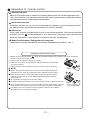
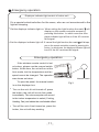
1
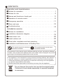
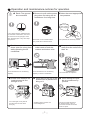
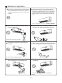
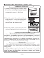
INSTALLATION MANUAL
Mini-Split Air Conditioner
YRHJZH018-24BAMKAFX
Read this manual before installation and operation
Make sure that it is well kept for later reference
CONTENTS
Operation and maintenance
■ Notices for operation ..................................1
■ Notices for use ......................................3
■ Names and functions of each part ......................... 5
■Operation of remote control................................6
■Emergency operation ................................11
■Clean and care ....................................12
■ Troubleshooting ....................................14
Installation service
■ Notices for installation ................................17
■ Installation dimension diagram ..........................19
■ Install indoor unit ...................................20
■ Install outdoor unit ..................................22
■ Check after installation and test operation ..................23
■ Installation and Maintenance of Healthy Filter ...............24
This symbol stands for the items
should be forbidden.
This symbol stands for the items
should be followed
The products in this manual may be different with the real one, according to different
models, some models have displayer and some models without displayer, the position
and shape of the displayer please refer to the real one.
This appliance is not intended for use by persons (including children) with reduced
physical, sensory or mental capabilities or lack of experience and knowledge,
unless they have been given supervision or instruction concerning use of the appliance
by a person responsible for their safety.
Children should be supervised to ensure they are away from the appliance.
Do not dispose this product as unsorted municipal waste.
Collection of such waste separately for special treatment
is necessary.
Operation and maintenance-notices for operation
★ Earth: The ground ★ Be sure to pull out the power ★ Select the most appropriate
be connected!
plug when not using the air
conditioner for a long time.
temperature.
Keep room cooler than outside
about 5 degree.
If not, please ask the qualified personnel to install. Furthermore, don't connect each wire to the gas pipe, water
pipe, drainage pipe or any other improper places.
Otherwise, the accumulated dust
may cause fire or electric shock.
★ Don't leave windows and ★ Don't block the air intake or
doors open for a long time
while operating the air
conditioner.
It can decrease the air conditioning
capacity.
★ Please note whether the
installed stand is firm
enough or not.
If it is damaged, it may lead to
the fall of the unit and cause
the injury.
outlet vents of both the
outdoor and indoor units.
It can decrease the air conditioning
capacity or cause a malfunction.
It can preclude the electricity wasted.
★ Keep combustible spray
away from the units more
than 1m.
It can cause afire or explosion.
★ Don't step on the top of the ★ Don't attempt to repair
outdoor unit or place somethe air conditioner by
yourself.
thing on it.
As falling off the outdoor unit
can be dangerous.
1
The wrong repair will lead to
an electric shock or fire, so
you should contact the service
center to repair.
Notices for operation
★ If the supply cord is damaged, it must be replaced
★ The airflow direction can be adjusted appro-
priately. At operating, adjust the vertical airflow
direction by adjusting the louvers of upward/downward direction. And then, hold two ends of
left and right louver to adjust the horizontal airflow.
by the manufacturer or its service agent or a
similarly qualified person in order to avoid a
hazard.
Louver of left/right direction
★
Don't insert your hands or stick into the air
intake or outlet vents.
Louver of upward/
downward direction.
★ Don't blow the wind to animals and plants
directly. It can cause a bad influence to them.
Otherwise it will cause accident.
★ Don't apply the cold wind to the body for a
long time.
★ Don't use the air conditioner for other purposes,
such as drying clothes, preserving foods, etc.
It can cause the health problems.
★ Splashing water on the air conditioner can
cause an electric shock and malfunction.
★ Don't place a space heater near the air
conditioner.
Or CO toxicosis may occur for imcomplete
burning.
2
Notices for use
Working principle and special functions for cooling
Principle:
Air conditioner absorbs heat in the room and transmit to outdoor and discharged, so that
indoor ambient temperature decreased, its cooling capacity will increase or decrease by
outdoor ambient temperature.
Anti-freezing function:
If the unit is running in COOL mode and in low temperature, there will be frost formed on
the heat exchanger, when indoor heat exchanger temperature decreased below 0℃ , the
indoor unit microcomputer will stop compressor running and protect the unit.
Working principle and special functions for heating
Principle:
* Air conditioner absorbs heat from outdoor and transmits to indoor, in this way to increase
*
room temperature. This is the heat pump heating principle, its heating capacity will be
reduced due to outdoor temperature decrease.
If outdoor temperature becomes very low, please operate with other heating equipments.
Defrosting:
* When outdoor temperature is low but high humidity, after a long while running, frost will
*
*
*
form on outdoor unit, that will effect the heating effect, at this time, the auto defrosting
function will act, the heat running will stop for 3-12 mins.
During the auto defrosting, the fan motors of indoor unit and outdoor unit will stop.
During the defrosting, the indoor indicator flashes, the outdoor unit may emit vapor.
This is due to the defrosting, it isn't malfunction.
After defrosting finished,the heating will recover automatically.
Anti-cool wind function:
In "Heat" mode, under the following three kinds of state, if indoor heat exchanger doesn't
arrive at certain temp., indoor fan will not act, in order to prevent cool wind blowing(within
2 mins):
1. Heating starts. 2. After Auto Defrost finished. 3. Heating under the low temperature.
3
Notices for use
Working temperature range
Indoor sideDB/WB(oC)
Outdoor sideDB/WB(oC)
Maximum cooling
32/23
43/26
Maximum heating
27/---
24/18
The operating temperature range (outdoor temperature) for cooling only unit is 18℃~ 43℃;
for heat pump unit is -7℃~ 43℃.
4
Names and functions of each part
Indoor unit
Air in
⑶
⑴
⑺
⑷
⑸
⑹
Air out
⑵
SET TEMP/
AMBIENT TEMP
Wireless
remote control
⑴ Power cable
Cool
Dry
Heat
Power
⑶ Front panel
Receive window
⑷ Filter
⑸ Guide louver
ON/OFF
⑵ Remote control
Outdoor unit
⑹ Wall pipe
Air in
⑺ Bind tape
⑻Drainage pipe
⑻
Air out
5
Operation of remote control
Names and functions of remote control buttons
Note: Be sure that there are no obstructions between receiver and remote control; Don't drop
or throw the remote control; Don't let any liquid in the remote control and put the remote control
directly under the sunlight or any place where is very hot.
(+/-)
Signal transmitter
●
FAN
AUTO
AIR HEALTH X-FAN
HUMIDITY
When press +button, the setting temp. will be
the button continuously and setting temp. range
is 16~30℃。
HOUR
ON/OFF
FAN
Remote control
ON/OFF
●
MODE
FAN speed button
Press this button once, fan speed will change
as below:
Auto
Low speed
FAN
ON/OFF
(+/-) button
increased by 1℃, When press - button, the
setting temp. will be decreased by 1 ℃
The temp. will be changed quickly by pressing
OPER
FILTER
TURBO
TEMP.
X-FAN
TEMP
TIMER
TURBO
SLEEP
LIGHT
Middle speed
High speed
Note: Under the Dry mode, the fan speed isn't
adjustable, low fan speed is imperative,
but when operating this button, the wireless
remote control will send this signal.
Swing up and down button
ON/OFF button
Simpleness swing mode is defaulted for wireless
remote control, in this mode, press this button,
● Press this button, the unit will be started or stopped,
could turn on or turn off the Up and down
which can clear the timer or sleeping function of
swing function.
last time.
●
When unit is turned off, synchronously press
"+" and Up and down swing buttons, it could
MODE
Mode button
be switched between the simpleness swing
● Press this button, the running mode will change as
mode and stationary swing mode, at this time,
below.
blinks 2 seconds.
AUTO
COOL
DRY
FAN
●
HEAT (Note:no for coolling only unit.
As for cooling only unit, it won’t have
any action when it receives the signal
of heating operation. )
●
In Stationary swing mode, press this button,the
angle for Up and down swing as show in below:
●
When up and down swing louver is working,
when turn off the unit, the siwng louver will
immediately stop at current position.
shows up and down swing louver swings back
and forth as show in the above figure.
6
Operation of remote control
Names and functions of remote control buttons
NOTE: This Remote control is universal, it could be used formany units, some buttons
of this control which are not available to this unit will not be described below.
FAN
TIMER
AUTO
OPER
AIR HEALTH X-FAN
HUMIDITY
●
FILTER
TURBO
HOUR
ON/OFF
ON/OFF
Remote control
HEALTH SAVE
MODE
FAN
X-FAN
TEMP
TIMER
TURBO
SLEEP
LIGHT
HEALTH SAVE
●
On the status of the unit on, press this
button to set timer off. On the status of
the unit off, press this button to set timer
off. Press this key once, words Hour on (off)
will appear and flicker. In which case, press
+/- button to adjust time (press+/- button
continuously to change timing value quickly),
the setting time range is from 0.5 to 24 hr.;
press this key once again to fix the time,
then remote controller will send out the signal
immediately and hour on/off will stop flickering.
If the time of that no press timer button
under flickering status is above 5s, the timer
setting will quit. If the timer has been set,
press this button once again to quit it.
button
Left and right swing button
HEALTH function: there is no this function
for this unit. If press this key, the main unit
will click, but it also runs under original status.
(This function is applicable to partial of models)
●
Timer button
●
There is no this function for this unit. If press
this key, the main unit will click, but it also
runs under original status.
HEALTH function: press the left part of this
button, can set up Health function on or off.
(This function is applicable to partial of models)
●
Save energy function: Under Cool mode, press
the right part of this button, the remote control
will display“
”, the whole unit will enter into
“Electricity Save mode”, repress this button,
TURBO
the whole unit will quit this mode, other mode
Turbo button
button is not available. Under the Energy Save
● Set turbo on or off (the characters of turbo
mode, the Temperature and the Fan speed
will appear or disappear) by pressing this
on the remote control are not adjustable.
key under cooling or heating mode. Once
energized, the unit will be defaulted to be
turbo off. This function can not be set under
auto, DRY or fan mode, and characters
of turbo won't appear.
7
Operation of remote control
Names and functions of remote control buttons
NOTE: This remote control is universal, it could be used formany units, some
buttons of this control which are not available to this unit will not be
described below.
X-FAN
X-FAN button
Set X-FAN on (the characters of X-FAN will
appear)or off (the characters of X-FAN
disappear ) by pressing this key under
cool or dehumidify mode. Once energized,
the unit will be defaulted to be X-FAN off.
This function can not be set under auto,
fan or heat mode, and the characters of
X-FAN won't appear.
Note: X-FAN is the alternative expression
of BLOW for the purpose of understanding.
LIGHT
Light button
●
FAN
AUTO
OPER
AIR HEALTH X-FAN
HUMIDITY
FILTER
TURBO
HOUR
ON/OFF
Remote control
ON/OFF
MODE
FAN
SLEEP
●
●
X-FAN
TEMP
TIMER
TURBO
SLEEP
LIGHT
Press this button to select LIGHT on or off
in the displayer. When the LIGHT on is
set,the icon
will be displayed and the
indicator light in the displayer will be on.
When the LIGHT off is set, the icon
will
be displayed and the indicator light in the
displayer will be off.
Sleep button
TEMP
Press this button, Sleep On and Sleep
Off can be selected. After powered on,
Sleep Off is defaulted. After the unit is
turned off, the Sleep function is canceled.
After Sleep function set up, the signal of
Sleep will display. In this mode, the time of
timer can be adjusted. Under Fan and Auto
modes, this function is not available.In
sleep mode, setting temperature is
adjusted automatically.
●
8
TEMP button
Press this button, could select displaying
the indoor setting temperature or indoor
ambient temperature. When the indoor unit
firstly power on it will display the setting
temperature, if the temperature's displaying
status is changed from other status to"
",
displays the ambient temperature, 5s later
or within 5s, it receives other remote control
signal that will return to display the setting
temperature. if the users haven't set up the
temperature displaying status, that will
display the setting temperature.
Operation of remote control
Guide for operation-general operation
1. Press ON/OFF button to start the unit after powering
the main unit on. (Note: Power the unit on every time,
the big -guide louver and small-guide louver will be
closed firstly.)
ON/OFF
MODE
2. Press MODE button to select desired running mode.
3. Press +/ - button to set the desired temperature.
FAN
(It is unnecessary to set the temperature at AUTO mode)
4. Press FAN button to set fan speed, the AUTO FAN,
LOW, MID or HIGH could be selected.
5. Press
X-FAN
TEMP
TIMER
TURBO
SLEEP
LIGHT
button to set swing mode.
Guide for operation-optional operation
1. Press SLEEP button, set the sleep mode.
2. Press TIMER button, then press +/- button, to set the
ON/OFF
MODE
cheduled timer on or timer off.
3. Press light button to control displayer light on or off.
FAN
4. Press X-FAN button to set X-FAN function on or off.
5. Press turbo button to set this function on or off.
X-FAN
TEMP
TIMER
TURBO
SLEEP
LIGHT
Introduction for special function
★ About X-FAN function
This function indicates that moisture on evaporator of indoor unit will be blowed after the unit
is stopped to avoid mould.
1. Having set X-FAN function on: After turning off the unit by pressing ON/OFF button
indoor fan will continue running for about 10 min. at low speed. In this period,
press X-FAN button to stop indoor fan directly.
2. Having set X-FAN function off: After turning off the unit by pressing ON/OFF button,
the complete unit will be off directly.
9
Operation of remote control
★ About AUTO RUN
When AUTO RUN mode is selected, the setting temperature will not be displayed on the
LCD, the unit will be in accordance with the room temp. automatically to select the suitable
running method and to make ambient comfortable.
★ About turbo function
If start this function, the unit will run at super-high fan speed to cool or heat quickly so that
the ambient temp. approachs the preset temp. as soon as possible.
★ About lock
Press +and - buttons simultaneously to lock or unlock the keyboard. If the remote controller
is locked, the icon
will be displayed on it, in which case, press any button, the mark will
flicker for three times. If the keyboard is unlocked, the mark will disappear.
★ About switch between Fahrenheit and Centigrade
Under status of unit off, press MODE and - buttons simultaneously to switch℃ and .
Changing batteries and notices
1. Slightly to press the place with
, along the arrowhead direction to push the back cover of wireless
remote control. (As show in figure)
2.Take out the old batteries. (As show in figure)
3. Insert two new AAA1.5V dry batteries, and pay attention to the polarity.
(As show in figure)
4. Attach the back cover of wireless remote control. (As show in figure)
★ NOTE:
● When changing the batteries, do not use the old or different batteries,
Fig.1
otherwise, it can cause the malfunction of the wireless remote control.
● If the wireless remote control will not be used for a long time, please
take them out, and don't let the leakage liquid damage the wireless
remote control.
● The operation should be in its receiving range.
● It should be placed at where is 1m away from the TV set or stereo sound sets. Fig.2
● If the wireless remote control can not operate normally, please take them out, Sketch map for
after 30s later and reinsert, if they cannot normally run, please change them.
● The battery must be removed from the appliance before it is scrapped.
The battery is to be disposed of safely
10
changing batteries
Emergency operation
Displayer indicator light control of indoor unit
It's a special selective button for the users, who are not accustomed to the
light at sleeping.
●
Get the displayer indicator light on: When setting the light function,the mark will
display on the remote controller screen by
pressing this button. In which case,the dissplayer indicator light will be on if the AC receives
this signal.
●
Get the displayer indicator light off: If cancel the light function,the mark will disapper on the remote controller screen by pressing this
button. In which case, the displayer indicator light will
be off if the AC receives this signal.
Emergency operation
If the wireless remote control is lost
or broken, please use the manual switch
button. At this time, the unit will run at the
Auto mode, but the temperature and fan
speed cannot be changed. The operation
was shown as below:
Manual switch
To open the panel, the manual switch
is on the displayer box.
●
Turn on the unit: At unit turned off, press
the button, the unit will run at Auto mode
immediately. The microcomputer will accord
to the indoor temperature to select (Cooling,
Heating, Fan) and obtain the comfortable effect.
●
Turn off the unit: At unit turned on, press the
button, the unit will stop working.
11
Fig.3
Clean and care
Caution
●
●
●
Turn power off and pull out the power plug before cleaning air conditioner, or it may cause electric
shock.
Never sprinkle water on the indoor unit and the outdoor unit for cleaning because it can cause an
electric shock.
Volatile liquid (e.g. thinner or gasoline) will damage the air conditioner. (So wipe the units with a
dry soft cloth, or a cloth slightly moistened with water or cleanser.)
Clean the front panel
When cleaning the front panel, please dip the cloth into the water temperature of 45℃ below, then to dry
the cloth and wipe the dirty part.
Note: Please do not to immerse the front panel in water, due to there are microcomputer components and
circuit diagrams on the front panel.
Clean the air filter (Recommended once every three months)
NOTE: If dust is much more around the air conditioner, the air filters should be cleaned many times.
After taking off the filter, don't touch the fin of indoor unit, in order to avoid hurt your fingers.
① Take down the air filter
At the slot of surface panel to open an angle, pull the air filter
downward and take it out, please see the Fig. 4(a, b).
(a)
(b)
② Clean the air filter
To clean the dust adhering to the filters, you can either
use a vacuum cleaner, or wash them with warm water
the water with the neutral detergent should below 45
degree), and dry it in the shade.
NOTE: Never use water above 45℃ to clean, or it can
cause deformation or discoloration. Never parch it by
fire, or can cause a fire or deformation.
③ Insert the air filter
Reinsert the filters along the direction of arrowhead, and
then to cover the cover and clasp it.
12
Fig.4
Clean and care
Check before use
①
Be sure that nothing obstructs the air outlet and intake vents.
②
Check that whether ground wire is properly connected or not.
③
Check that whether the batteries of air conditioner are
changed or not.
④
Check that whether the installation stand of the outdoor
unit is damaged or not. If damaged, please contact the dealer.
Maintain after use
①
Turn main power off.
②
Clean the filter and indoor and outdoor units' bodies.
③
Clear dust and obstructions from the outdoor unit.
④
Repaint the rubiginous place on the outdoor unit to prevent it from spreading.
⑤
Adopt the special shield to cover the outdoor unit, avoid the rain water, dust enter into
the unit and get rust.
13
Troubleshooting
CAUTION
Don't attempt to repair the air conditioner by yourself, it can cause an electric shock or
fire. Please check the following items before asking for repair, it can save your time and
money.
Phenomenon
Troubleshooting
Not operate immediately when the air
conditioner is restarted.
Once the air conditioner is stopped, it will
not operate in approximately 3 minutes to
protect itself.
●
Waiting
There's unusual smell blowing from the outlet
after operation is started.
● The
unit has no peculiar smell by itself. If has
that is due to the smell accumulated in the
ambient.
● Solution
method: Cleaning the filter.
If problem still has, so need to clean air
conditioner. (Please contact with the authorized
maintenance center.)
Sound of water flow can be heard during
the operation.
In COOL mode, sometimes the mist emitted
from the air outlet vent.
Creaking noise can be heard when start or
stop the unit.
●
The air conditioner is started, when it is
running the compressor started or stopped
running, or the unit is stopped, sometimes
there is swoosh or gurgle, the sound is due
to refrigerant flowing they are not malfunctions.
●
When the indoor temperature and humidity
are very high, this phenomenon would
happen. This is caused by the room air is
swiftly cooled down. After running for a while,
indoor temperature and humidity will fall
down, the mist will die away.
●
This is caused by the deformation of plastic
due to the changes of temperature.
14
Troubleshooting
Phenomenon
Troubleshooting
● Has the power been shut down?
The unit can not run.
● Is power plug loosed?
● Is the circuit protection device tripped off or not?
● Is voltage higher or lower?
(Tested by professionals)
Breaking off
Cooling(Heating) efficiency is not good.
● Is the TIMER correctly used?
● Is Temp. setting suitable?
● Were inlet and outlet vents obstructed?
● Is filter dirty?
● Are the windows and doors clothed?
● Did Fan speed set at low speed?
● Is there any heat sources in the room?
Wireless remote control is not available.
● The unit is interfered by abnormal or frequent
functions switchover occasionally the controller
cannot operate. At this time, you need to pull out
of the plug, and reinsert it.
● Is it in its receiving range? Or obstructed?
To check the voltage in wireless remote control inside
is charged, otherwise to replace the batteries.
● Whether the wireless remote control is damaged.
If water leakage in the room.
● The air humidity is on the high side.
● Condensing water over flowed.
● The connection position of indoor unit drainage
pipe is loosed.
If water leakage in outdoor unit.
● When the unit is running in COOL mode, the pipe
and connection of pipe would be condensed due
to the water cooled down.
● When the unit is running in Auto Defrosting mode
the ice thawed and flowed out.
● When the unit is running in HEAT mode, the water
adhered on heat exchanger dripped off.
Noise from indoor unit emitted.
● The sound of fan or compressor relay is switching
on or off.
● When the defrosting is started or stop running,
it will sound. That is due to the refrigerant flowed
to the reverse direction.
15
Troubleshooting
Phenomenon
Indoor unit cannot deliver air.
Troubleshooting
●
In HEAT mode, when the temperature of indoor
heat exchanger is very low, that will stop deliver
air in order to prevent cool air. (Within 2min)
●
In HEAT mode, when the outdoor temperature
is low or high humidity, there are much frost be
formed on the outdoor heat exchanger, that the
unit will automatically defrost, indoor unit stop
blowing air for 3-12min.
During the defrosting, there is water flowing out
or vapor be produced.
● In dehumidifying mode, sometimes indoor fan will
stop, in order to avoid condensing water be vaporized again, restrain temperature rising.
Moisture on air outlet vent.
●
If unit is running under the high humidity for
a long time, the moisture will be condensed
on the air outlet grill and drip off.
H1: Defrosting
●
It is normal.
Immediately stop all operations and plug out, contact
the dealer in following situations.
There is harsh sound during operation.
The terrible odors emitted during operation.
Water is leaking in the room.
Air switch or protection switch often breaks.
Carelessy splash water or something into unit.
There is an abnormal heat in power supply cord
and power plug.
16
Stop running and pull out of the plug.
Notices for installation
Important Notices
1. The unit installation work must be done by qualified personnel according to the local
rules and this manual.
2. Before installating, please contact with local authorized maintenance center, if unit is
not installed by the authorized maintenance center, the malfunction may not solved,
due to discommodious contacts.
3. When removing the unit to the other place, please firstly contact with the authorized
Maintenance Center in the local area.
4. the appliance must be positioned so that the plug is accessible.
Basic Requirements For Installation Position
Install in the following place may cause malfunction. If it is unavoidable contact with
service center please:
● Place where strong heat sources, vapors, flammable gas or volatile object are emitted.
● Place where high-frequency waves are generated by radio equipment, welders and
medical equipment.
● Place where a lot of salinities such as coast exists.
● Place where the oil (machine oil) is contained in the air.
● Place where a sulfured gas such as the hot spring zones is generated.
● Other place with special circumstance.
Indoor Unit Installation Position Selection
1. The air inlet and outlet vent should be far from the obstruction, make sure that the air
can be blown through the whole room.
2. Select a position where the condensing water can be easily drained out, and the place
is easily connected for outdoor unit.
3. Select a location where the children can not reach.
4. Can select the place where is strong enough to withstand the full weight and vibration o f
the unit. And will not increase the noise.
5.Be sure to leave enough space to allow access for routine maintenance. The height of the
installed location should be 250cm or more from the floor.
6.Select a place about 1m or more away from TVset or any other electric appliances.
7. Select a place where the filter can be easily taken out.
8. Make sure that the indoor unit installation should accord with installation dimension
diagram requirements.
9. Do not use the unit in the immediate surroundings of a laundry a bath a shower or a
swimming pool.
Outdoor Unit Installation Position Selection
1. Select a location from which noise and outflow air emitted by unit will not inconvenience
neighbors, animals, plants.
2. Select a location where there should be sufficient ventilation.
3. Select a location where there should be no obstructions cover the inlet and outlet vent.
4. The location should be able to withstand the full weight and vibration of the outdoor unit
and permit safe installation.
5. Select a dry place, but do not expose under the direct sunlight or strong wind.
6. Make sure that the outdoor unit installation dimension should accord with installation
dimension diagram, convenient for maintenance, repair.
7. The height difference of connecting the tubing within 5m, the length of connecting the
tubing within 10m.
8. Select a place where it is out of reach for the children.
9. Select a place where will not block the passage and do not influence the city appearance.
17
Notices for installation
Safety Requirements For Electric Appliances
1. The power supply should be used the rated voltage and AC exclusive circuit,
the power cable diameter should be satisfied.
2. Don't drag the power cable emphatically.
3. It should be reliably earthed, and it should be connected to the special earth device,
the installation work should be operated by the professional.
The air switch must have the functions of magnetic tripping and heat tripping, in order
to protect the short circuit and overloading.
4. The min. distance from the unit and combustive surface is 1.5m.
5. The appliance shall be installed in accordance with national wiring regulations.
6. An all-pole disconnection switch having a contact separation of at least 3mm in all poles
should be connected in fixed wiring. For models with a power plug, make sure the plug
is within reach after installation.
Note:
●
●
Make sure that the Live wire or Zero line as well as the earth wire in the family power
socket can not be wrong connected, there should be reliable and no short circuit in the
diagram.
wrong connection may cause fire.
Air-conditioner (Btu/h)
Air switch capacity
18、24K
25A
Earthing requirements
1. Air conditioner is type I electric appliance, thus please do conduct reliable earthing
measure.
2. The yellow-green two-color wire in air conditioner is earthing wire and cannot be used
for other propose. It cannot be cut off and be fix it by screw, otherwise it would cause
electric shock.
3. The earth resistance should accord to the National Criterion.
4. The user power must offer the reliable earthing terminal. Please don't connect the
earthing wire with the following place:
① Tap water pipe. ② Gas pipe.
③ Contamination pipe.
④ Other places that professional personnel consider them unreliable.
5. Including an air switch with suitable capacity, please note the following table. Air switch
PCB board.should be included magnet buckle and heating buckle function, it can protect
the circuit-short and overload. (Caution: please do not use the fuse only for protect
the circuit)
18
Installation dimension diagram
Installation dimension diagram
Space to the ceiling
Above
Space to the wall
Above
Above
Space to the wall
Above
Air outlet side
Space to the floor
The dimensions of the space necessary for correct
installation of the appliance including the minimum
permissible distances to adjacent structures
Space to the obstruction
Above
●
Above
Air inlet side
e
ov
Ab
Above
Space to the wall
Space to the wall
Above
ve
o
Ab
Air outlet side
19
Install indoor unit
Install the rear panel
1. Always mount the rear panel horizontally. Due to the water tray of indoor unit has been adopted the
both-way drainage design, the outlet of water tray should be adjusted slightly down when installing, that is
taking the outlet of the water tray as the center of a circle, the included angle between the evaporator and
level should be 0 or more, that is good for condensing water drainage.
2. Fix the rear panel on the wall with screws.
18K:
(Where is pre-covered with plastic granula) Wall
Wall
3. Be sure that the rear panel has been fixed
firmly enough to withstand the weight of an
adult of 60kg, further more, the weight should
be evenly shared by each screw.
Space
to the
wall
150mm
above
Mark on the middle of it
Left
Ф 55mm
Gradienter
Right
(Rear piping hole)
24K:
Wall
Space
to the
wall
150mm
above
Mark on the middle of it
Gradienter
Left
Ф 65mm
Space
to the
wall
150mm
above
Right
(Rear piping hole)
Install the piping hole
Indoor
1. Make the piping hole (Ф55、Ф65) in the wall at a slight downward
slant to the outdoor side.
all
Wall
Ф 65mm
Fig.5
(Rear piping hole)
Wall pipe
Outdoor
Seal pad
2. Insert the piping-hole sleeve into the hole to prevent the connection piping
and wiring from being damaged when passing through the hole.
Ф
Ф 55、
65
Install the water drainage pipe
1. For well draining, the drain hose should be placed at a downward slant. Wrenched
2. Do not wrench or bend the drain hose or flood its end by water.
Bent
3. When the long drainage hose passing through indoor,
should wrap the insulation materials.
Flooded
Connect indoor and outdoor electric wires
1. Open the surface panel.
2. Remove the wiring cover.
. Route the power connection cord from the back of the indoor unit and pull it toward the
3
front through the wiring hole for connection.
4. Connect the interconnection cord to the terminal block, and then fix the cord with cord anchorge.
5. Reassemble the clampand wiring cover.
6. Recover the surface panel.
for some model
for some model
N(1)
2
N(1)
3
blue black brown
yellowgreen
outdoor unit connection
20
m
Ф 55mm
Fig.5
(Rear piping hole)
Space
to the
wall
150 m
above
2
3
blue black brown
yellowgreen
outdoor unit connection
Install indoor unit
NOTE:
When connecting the electric wire if the wire length is not enough, please contact with
the authorized service shop to buy a exclusive electric wire that is long enough and the
joint on the wire are not allowed.
The electric wiring must be correctly connected, wrong connection may cause spare parts
malfunction.
● Tighten the terminal screw in order to prevent loose.
● After tighten the screw, slight pull the wire and confirm whether is it firm or not.
●
●
If the earth wire is wrong connection, that may cause electric shock.
● The
cover plate must be fixed, and tighten the connection wire, if it is poor installed, that
the dust, moisture may enter in or the connection terminal will be affected by outside force,
and will cause fire or electric shock.
Install the indoor unit
The piping can be lead out from right, right rear, left
left rear.
1.When routing the piping and wiring from the left
or right side of indoor unit, cut off the tailings
from the chassis in necessary(Show in Fig.6)
⑴ Cut off the tailings 1 when routing the wiring only;
⑵ Cut off the tailings 1 and tailings 2 when routing
both the wiring and piping.
2.Take out the piping from body case, wrap the piping
electric wire, water pipe with tape and pull them
through the piping hole (As show in Fig.7)
3.Hange the mounting slots of the indoor unit on the
upper tabs of the rear panel and check if it is firm
enough.(As show in Fig.8)
4.The height of the installed location should be 2.5m
or more from the floor.
Gas side pipe
●
Fig.6
Tailing 2
side piping
Tailing 1 Gas
insulation
Liquid side
Piping insulation
Finally wrap it
Water drainage pipe
with tape
Left
右后
Right
External connection
electric wire
Liquid side piping
Left rear
Right rear
Fixing hook
Mounting
plate
Fig.7
Mounting
baord
Fig.8
Install the connection pipe
1. Align the center of the piping flare with the relevant valve.
2.Screw in the flare nut by hand and then tighten the
nut with spanner and torque wrench refer to the
following:
Hex nut diameter
Ф6
Ф 9.52
Ф 12
Ф 16
Ф 19
Tightening torque(N·m)
15~20
31~35
50~55
60~65
70~75
Indoor unit piping
Spanner
Taper nut Piping
Torque
wrench
NOTE: Firstly connect the connection pipe to indoor unit, then to outdoor unit; pay attention
to the piping bending, do not damage the connection pipe; the joint nut couldn't tighten too
much, otherwise it may cause leakage.
21
Install outdoor unit
Electric wiring
1. Disassemble the handle on the outdoor unit right side plate.
2.Take off cord anchorage. Connect and fix power connect
cord (for cooling and heating unit,connect and fix power
connect cord)to terminal block.
3
Handle
3.Fix the power connection cable with cord anchorage,
blue
black
yellowgreen
brown
(for cooling and heating unit, use the cord anchorage
to fix the power connection cable control wire).
wire clamp
power connect wire
4. Ensure wire has been fixed well.
INDOOR/OUTDOOR
CONNECT FIG
5. Install the handle.
NOTE:
● Wrong wiring may cause spare parts malfunction.
● After the cable fixed, make sure there should be
a free space between the connection and
connection and fixing place on the lead wire.
INDOOR
3
power
connect
wire
blue black brown
yellowgreen
3
OUTDOOR
Air purging and leakage test
1. Connect charging hose of manifold valve to charge end of low pressure
valve (both high/low pressure valves must be tightly shut).
Multimeter Manifold
2. Connect joint of charging hose to vacuum pump.
Valve
-76cmHg
3. Fully open handle handle of Lo manifold valve.
Lo Handle
Hi handle
4. Open the vacuum pump to evacuate. At the beginning, slightly
Charging hose
loosen joint nut of low pressure valve to check if there
Low pressure valve
Charging hose
is air coming inside. (If noise of vacuum pump has
been changed, the reading of multimeter is 0) Then
tighten the nut.
Vacuum pump
5. Keep evacuating for more than 15mins and make
sure the reading of multi-meter is -1.0 105pa
(-76cmHg)..
6. Fully open high/low pressure valves.
7. Remove charging hose from charging end of low pressure valve.
8. Tighten bonnet of low-pressure valve. (As shown in Fig.9)
Fig.9
Condensate drainage of outdoor unit (no for cooling only)
The condensate and defrosting water formd during heating
in the outdoor unit can be properly discharged by drainage
pipe .
Installation method:set the drain connection in Ø 25 hole of the
chassis has been installed and then connect drainage pipe
with drain nozzle, so that condensate and defrosting waer can
be properly discharged
22
Chassis
Drain
connection
Check after installation and test operation
Check after installation
Items to be checked
Possible malfunction
Has it been fixed firmly?
The unit may drop, shake or emit noise.
Have you done the refrigerant leakage test?
It may cause insufficient cooling(heating)
capacity
Is heat insulation sufficient?
It may cause condensation and dripping.
Is water drainage well?
It may cause condensation and dripping.
Is the voltage in accordance with the rated
voltage marked on the nameplate?
Is the electric wiring and piping
connection installed correctly and securely?
Has the unit been connected to a secure
earth connection?
It may cause electric malfunction
or damage the part.
It may cause electric malfunction
or damage the part.
It may cause electrical leakage.
Is the power cord specified?
It may cause electric malfunction
or damage the part.
Is the inlet and outlet been covered?
It may cause insufficient cooling(heating)
capacity.
Has the length of connection pipes
and refrigerant capacity been recorded?
The refrigerant capacity is not accurate.
Test Operation
1. Before test operation
(1)Do not switch on power before installation isfinished completely.
(2)Electric wiring must be connected correctly and securely.
(3)Cut-off valves of the connection pipes should be opened.
(4)All the impurities such as scraps and thrums must be cleared from the unit.
2.Test operation method
(1)Switch on power, press "ON/OFF" button on the wireless remote control to start
the operation.
(2)Press MODE button, to select the COOL, HEAT (Cooling only unit is not available),
FAN to check whether the operation is normal or not.
23
Installation and Maintenance of Healthy Filter
Installation Instructions
1. Forcibly pull the panel for a specific angle
from the two ends of the front panel according
to the arrow direction. Then pull the air filter
downwards to remove it. (See Fig.a)
Fig. a
2. Mount the healthy filter onto the air filter,(as
shown in Fig.b). If the air filter cannot be installed, please mount the healthy filter on
the front case. (as shown in Fig.c)
Fig. b
Air filter
Healthy filter
Healthy filter
Fig. c
3. Mount the air filter properly along the arrow
direction in Fig.d, and then close the panel cover.
Fig. d
Cleaning and Maintenance
Take out the healthy filter before cleaning and reinstall it after cleaning
according to the installation instruction. Pay special attention to that silver
ion filter can't be cleaned with water, while active carbon, photocatalyst,
low temperature conversion (LTC) catalyst, formaldehyde eliminator, catechin or mite killing filter can, but can't with brush or hard things. Dry it in
the shade or sun after cleaning, but not by wiping.
Service Life
The healthy filter commonly has its usage lifetime for one year under
normal condition. As for silver ion filter, it is invalid when its surface becomes
black (green).
● This supplementary instruction is provided for reference to the unit with
healthy filter. If the graphics provided herein is different from the physical
goods, the latter one shall prevail. The quantity of healthy filters shall be
based on the actual delivery.
24
2011 Johnson Con trols, Inc.
www.johnsoncontrols.com
Form No. URHJZHAMQ-111213
Johnson Controls reserve the right to change product features without prior notice.