1
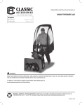
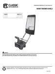
ITEM/ARTÍCULO/ARTICLE #52-002-010401-00 DELUXE SNOW THROWER CAB English Español Français (página 13) (page 25) WARNING READ YOUR INSTRUCTIONS COMPLETELY AND CAREFULLY BEFORE ATTEMPTING TO SET UP YOUR NEW DELUXE SNOW THROWER CAB OR OPERATE YOUR SNOW THROWER WITH YOUR CAB INSTALLED. A video of this installation is available for download at: www.classicaccessories.com/instructions Questions, problems, missing parts? Before returning to your retailer, call Classic Accessories customer service at 1-800-854-2315, 8 a.m. - 4 p.m., PST, Monday-Friday. Email: [email protected] 08cH56_10159 TABLE OF CONTENTS Safety Information.................................................................................................................................................................................. 2 Package Contents List (Parts and Hardware)........................................................................................................................................ 3 Package Contents List (Soft Parts)........................................................................................................................................................ 4 Preparation............................................................................................................................................................................................. 5 Assembly Instructions....................................................................................................................................................................... 5-10 Care and Maintenance..........................................................................................................................................................................11 Troubleshooting.....................................................................................................................................................................................11 Warranty.................................................................................................................................................................................................11 Replacement Parts................................................................................................................................................................................11 SAFETY INFORMATION Please read and understand this entire manual before attempting to assemble, operate or install the product. If you have any questions regarding the product please call Classic Accessories customer service at 1-800-854-2315, 8 a.m. - 4 p.m., PST, Monday-Friday. 1. THE CAB IS NOT A PROTECTIVE DEVICE. The cab will NOT protect against noise, engine exhaust, chemicals, collision, roll-over or other accidents. 2.Follow all your snow thrower manufacturer’s recommended safety instructions. 3. Operating a snow thrower with this cab will restrict your field of vision. Watch carefully for people, children, obstructions or obstacles. 4. The cab adds height to your snow thrower. Remember the height of your cab. Watch carefully for tree limbs or other items overhead that you could previously go under without a cab. 5. Before use be sure that all bolts are tight. If one or more bolts comes loose failure of cab parts may occur. 6. NO PART OF THE FABRIC CAB SKIN SHOULD TOUCH THE ENGINE OR EXHAUST SYSTEM OF YOUR SNOW THROWER. 2 Package contents list (PARTS) Frame Parts Frame Parts (Continued) Part A Description Quantity Part Center Mounting Bar 1 J1, J2 Description Quantity Mounting Post, Upper 2 B1, B2 Side Mounting Bar 2 K1, K2 Mounting Post, Lower 2 C1, C2 Mounting Bar End 2 L1, L2 Mounting Post Clamp 2 D1, D2 Front Poles 2 M1, M2 Mounting Post Clamp Spacer 2 E Back Hoop Side Poles 4 F Back Hoop Corner Poles 2 G Back Hoop Top Pole 1 H Front Hoop Side Poles 4 Part I Front Hoop Top Pole 1 N U Bolt 4 O Nylock Nut 8 P Allen Wrench 1 Hardware Parts Description Quantity F G J1, J2 K1, K2 E F M1, M2 L1, L2 E H I E D1 N E C1 B1 D2 A O B2 C2 3 P Package contents list (CONTINUED) SOFT PARTS Please note: Some parts listed may not be used during installation. The use of some parts are dependent on the model of your snow thrower. Part Description Q R1, R2 S Quantity Cab Fabric Skin 1 Removable Sand/Salt Pockets 2 Removable Garage Door Opener Storage Pocket 1 Q R1, R2 S 4 PREPARATION Before beginning assembly, installation or operation of the product, make sure all parts are present. Compare parts with the package contents list and diagram. If any part is missing or damaged, do not attempt to assemble, install or operate the product. Contact customer service for replacement parts. Estimated Assembly Time: 30-40 minutes Tools Required for Assembly: • Adjustable wrench or one 1/2 in. box end or socket wrench Assembly instructions Install the mounting post Clamps (Figs. 1 and 2) Front side of snow thrower handlebar upright 1. Insert two U-bolts [P] around the Snow Thrower frame and through the mounting post clamp spacer [M1, M2] and the mounting post clamp [L1, L2] as shown. (Fig. 1) Note: Exact positioning may vary depending on manufacture. 2. Install two Nylock nuts [O] to each U-bolt. Snug but do not fully tighten. Leave the nuts loose for final adjustments of the mounting posts. (Fig. 2) L Note: In some instances, it may be necessary to mount the top U-bolts above the handlebar crossbar support. (Fig. 2b) This will help the assembled cab sit higher for added clearance. Repeat on other side. M CAUTION: Position of the clamps may vary depending on Snow Thrower Manufacturer Fig. 1 CAUTION: Make sure nothing interferes with the safe operation of your snow thrower Top U-bolt may need to be on top of handlebar crossbar. Fig. 2 5 Fig. 2b Install the Lower mounting posts (fig. 3) 3. Insert lower mounting posts [K1, K2] into mounting post clamps as shown. Snug but do not fully tighten. Leave the nuts loose for final adjustments of the mounting posts. (Fig. 3) K Fig. 3 Install the Upper mounting posts (Fig. 4) 4. Insert upper mounting posts [J1, J2] into lower mounting posts as shown. (Fig. 4) Do not tighten set screw at this time. See step 6. P J Fig. 4 6 Install the center and side mounting bars (fig. 5) 5. Slide side mounting bars [B1, B2] through each upper mounting post. Connect the center mounting bar [A] to both side mounting bars by engaging the spring loaded pins as shown. (Fig. 5) B2 6. Snug but do not fully tighten. Leave the nuts loose for final adjustments of the mounting posts. Tighten set screws on the lower mounting posts with supplied Allen wrench [P]. Fig. 4 B1 A Fig. 5 Assemble the rest of the frame (fig. 6) F 7. Insert the mounting bar ends [C1, C2] into the side mounting bars by engaging the spring load pins. G 8. Install each front pole [D1, D2] into the protruding stud on the top of each side mounting bar. Note: You must first remove the protective plastic caps off the protruding studs on each side mounting bar [B1, B2]. E 9. Insert the back hoop side poles [E] first into each side mounting bars. Insert another pair of back hoop side poles into the tops of the ones installed on the side mounting bars. Insert the back hoop corner poles [F] into the tops of the installed sections of back hoop side poles. Finish by inserting the back hoop top pole [G] into both back hoop corner poles. Note: It may help to place the parts flat on the ground for easier assembly. Note: The back hoop side and corner poles each have clear plastic sleeves on one end. The frame hoop top pole DOES NOT have clear plastic sleeves. F E E Fig. 6 D1 C1 E D2 Remove protective plastic caps from these metal studs prior to assembly C2 7 Install the FRONT HOOP POLES (fig. 7) I 10. Insert the front hoop side poles [H] first into each assembled front pole [D1, D2] on the frame. Insert another pair of front hoop side poles into the one installed on the front poles. Finish by carefully inserting the front hoop top pole [I] into both the top most front hoop side poles, forming a curve. The curved poles will be standing quite high up in the air. This is normal. (Fig. 7) Note: The front hoop side poles each have a metal/PVC sleeve on one end. The front hoop top pole DOES NOT have a sleeve on either end. During assembly, make sure the poles end with the PVC sleeves face up. H H H CAUTION: Use care when assembling the front hoop side and top poles. Poles under tension can slip out of the metal/ PVC sleeves causing serious injury H Fig. 7 Install the fabric cab skin to the assembled frame (fig. 8) 11. Unfold the fabric cab skin [Q] and find the pocket sewn into the top rear part of the cab skin roof. Carefully insert the top curved section of the assembled front hoop poles into the pocket on the cab skin. The front hoop poles and roof of the cab skin will rest on top of the assembled frame hoop poles. (Fig. 8) 12. Unfold the rest of the cab skin and drape over the assembled frame as shown. CAUTION: No part of the fabric cab skin should touch the engine or exhaust system of your snow thrower. Note: The lower front panel features two double zippers that allow convenient passthrough of cables or linkages if necessary Fig. 8 8 Secure Fabric Cab Skin to Frame (fig. 9) 13. Find the large fabric strap sewn into the bottom rear area of the fabric cab skin. Pull the strap down and over the end of both mounting bar ends [C1, C2]. (Fig. 9) Find all rip and grip tabs on the inside of the cab skin and secure the skin to the frame. Note: If it is very difficult to secure straps over the mounting bar ends, make sure that all rip and grip tabs are loose and that the skin is fitted correctly. Fig. 9 Secure Pockets to cab skin and Frame (fig. 10) 14. Find the two sand/salt pouches [R1, R2] and the mesh garage door opener holder [S]. Secure the large pouches to the top arch of the mounting bar ends using the rip and grip strips. On the left side of the inside of the fabric skin there is a loose fabric gusset. Secure the garage door opener holder to the gusset with rip and grip strips. (Fig. 10) Fig. 10 9 Fine tune the placement of the cab on snow thrower and secure 15. Adjust the cab so it is centered over the controls and the angle of the mounting bar ends are parallel to the ground by loosening the upper mounting post adjustment nut and/or the set screw and readjusting. Fully tighten all nuts and screws when complete. Enjoy your new Snow Thrower Cab! 10 CARE AND MAINTENANCE STORAGE Store in a clean dry place. Never store a wet cover in an enclosed area as it can develop mildew. Avoid folding the plastic windows of the cover for long periods. BOLTS Check all bolts before each use to see that they are tight. If one or more bolts come loose, failure of cab parts may occur. WINDOWS Don't clean the plastic windows when they are dry—you can scratch them. Hose them with water and rub them with your bare hands. Liquid soap may be used. During freezing weather an automotive windshield solvent and a soft cloth will work (don't use your bare hands with the solvent). Fabric areas of the cab may be washed with a rag. Don't use soap as it may remove protective coatings added by the factory. TROUBLESHOOTING Problem Possible Cause Corrective Action Cab front interferes with the snow thrower controls. Upper horizontal mounting bar [A, B1 & B2] is mounted too low. 1. Rotate cab forward. 2. Move cab sideways. Not enough headroom. Upper horizontal mounting bar [A, B1 & B2] is mounted too low. 1. Rotate cab forward. 2. Raise attachment point WARRANTY The manufacturer, Classic Accessories, Inc., will repair or replace, without charge, this product which under normal usage has proven to be defective in its manufacture or workmanship for a period of two (2) year from the date of initial retail purchase. This warranty is valid only to the original purchaser. This warranty is not transferable and does not cover any parts that have been subjected to misuse, abuse, alteration, overload, accident or normal wear of moving parts. Service can be obtained by contacting Classic Accessories at 1-800-854-2315. Any cab or cab part that is returned to Classic Accessories, together with the original sales receipt as proof of initial retail purchase, and with postage prepaid, will be repaired or replaced without cost if the unit is found defective. This warranty does not apply to accessories or damage caused where repairs have been made or attempted by others. All warranty work will be completed in a reasonable time, not to exceed 60 days after receiving the product. Classic Accessories is not responsible for direct, indirect, incidental or consequential damages. Some states do not allow limitations on how long an implied warranty lasts and/or do not allow the exclusion or limitation of incidental damages, so the above limitations may not apply to you. This warranty gives you specific legal rights, and you may also have other rights, which vary from State to State. WARRANTY VOID IF PRODUCT USED FOR COMMERCIAL OR RENTAL PURPOSES OR IF THE DELUXE SNOW THROWER CAB IS TRANSPORTED ON AN OPEN TRAILER OR TRUCK. Call: 1-800-854-2315 for Warranty Assistance, Monday - Friday 8:00 a.m. - 4:00 p.m., PST replacement parts If parts are missing or if you need replacement parts, please call Classic Accessories customer service at 1-800-854-2315, 8 a.m. - 4 p.m., PST, Monday-Friday. Please refer to the Package Contents List for the parts list. 11 22640 68th Ave. S. Tel: (253)395-3900 Kent, WA, USA 98032 Fax: (253)395-3991 www.classicaccessories.com Email: [email protected] © 2008 Designed in the U.S.A. 08cH56_10159 Printed in China