1
Catalyst 2984G, 2948G-GE-TX,
and 2980G Switch Hardware
Installation Guide
October 2003
Corporate Headquarters
Cisco Systems, Inc.
170 West Tasman Drive
San Jose, CA 95134-1706
USA
http://www.cisco.com
Tel: 408 526-4000
800 553-NETS (6387)
Fax: 408 526-4100
Customer Order Number: DOC-786286=
Text Part Number: 78-6286-05
THE SPECIFICATIONS AND INFORMATION REGARDING THE PRODUCTS IN THIS MANUAL ARE SUBJECT TO CHANGE WITHOUT
NOTICE. ALL STATEMENTS, INFORMATION, AND RECOMMENDATIONS IN THIS MANUAL ARE BELIEVED TO BE ACCURATE BUT
ARE PRESENTED WITHOUT WARRANTY OF ANY KIND, EXPRESS OR IMPLIED. USERS MUST TAKE FULL RESPONSIBILITY FOR
THEIR APPLICATION OF ANY PRODUCTS.
THE SOFTWARE LICENSE AND LIMITED WARRANTY FOR THE ACCOMPANYING PRODUCT ARE SET FORTH IN THE INFORMATION
PACKET THAT SHIPPED WITH THE PRODUCT AND ARE INCORPORATED HEREIN BY THIS REFERENCE. IF YOU ARE UNABLE TO
LOCATE THE SOFTWARE LICENSE OR LIMITED WARRANTY, CONTACT YOUR CISCO REPRESENTATIVE FOR A COPY.
The following information is for FCC compliance of Class A devices: This equipment has been tested and found to comply with the limits for a Class
A digital device, pursuant to part 15 of the FCC rules. These limits are designed to provide reasonable protection against harmful interference when
the equipment is operated in a commercial environment. This equipment generates, uses, and can radiate radio-frequency energy and, if not installed
and used in accordance with the instruction manual, may cause harmful interference to radio communications. Operation of this equipment in a
residential area is likely to cause harmful interference, in which case users will be required to correct the interference at their own expense.
The following information is for FCC compliance of Class B devices: The equipment described in this manual generates and may radiate
radio-frequency energy. If it is not installed in accordance with Cisco’s installation instructions, it may cause interference with radio and television
reception. This equipment has been tested and found to comply with the limits for a Class B digital device in accordance with the specifications in
part 15 of the FCC rules. These specifications are designed to provide reasonable protection against such interference in a residential installation.
However, there is no guarantee that interference will not occur in a particular installation.
Modifying the equipment without Cisco’s written authorization may result in the equipment no longer complying with FCC requirements for Class
A or Class B digital devices. In that event, your right to use the equipment may be limited by FCC regulations, and you may be required to correct
any interference to radio or television communications at your own expense.
You can determine whether your equipment is causing interference by turning it off. If the interference stops, it was probably caused by the Cisco
equipment or one of its peripheral devices. If the equipment causes interference to radio or television reception, try to correct the interference by
using one or more of the following measures:
• Turn the television or radio antenna until the interference stops.
• Move the equipment to one side or the other of the television or radio.
• Move the equipment farther away from the television or radio.
• Plug the equipment into an outlet that is on a different circuit from the television or radio. (That is, make certain the equipment and the television
or radio are on circuits controlled by different circuit breakers or fuses.)
Modifications to this product not authorized by Cisco Systems, Inc. could void the FCC approval and negate your authority to operate the product.
The Cisco implementation of TCP header compression is an adaptation of a program developed by the University of California, Berkeley (UCB) as
part of UCB’s public domain version of the UNIX operating system. All rights reserved. Copyright © 1981, Regents of the University of California.
NOTWITHSTANDING ANY OTHER WARRANTY HEREIN, ALL DOCUMENT FILES AND SOFTWARE OF THESE SUPPLIERS ARE
PROVIDED “AS IS” WITH ALL FAULTS. CISCO AND THE ABOVE-NAMED SUPPLIERS DISCLAIM ALL WARRANTIES, EXPRESSED
OR IMPLIED, INCLUDING, WITHOUT LIMITATION, THOSE OF MERCHANTABILITY, FITNESS FOR A PARTICULAR PURPOSE AND
NONINFRINGEMENT OR ARISING FROM A COURSE OF DEALING, USAGE, OR TRADE PRACTICE.
IN NO EVENT SHALL CISCO OR ITS SUPPLIERS BE LIABLE FOR ANY INDIRECT, SPECIAL, CONSEQUENTIAL, OR INCIDENTAL
DAMAGES, INCLUDING, WITHOUT LIMITATION, LOST PROFITS OR LOSS OR DAMAGE TO DATA ARISING OUT OF THE USE OR
INABILITY TO USE THIS MANUAL, EVEN IF CISCO OR ITS SUPPLIERS HAVE BEEN ADVISED OF THE POSSIBILITY OF SUCH
DAMAGES.
CCIP, CCSP, the Cisco Arrow logo, the Cisco Powered Network mark, Cisco Unity, Follow Me Browsing, FormShare, and StackWise are trademarks
of Cisco Systems, Inc.; Changing the Way We Work, Live, Play, and Learn, and iQuick Study are service marks of Cisco Systems, Inc.; and Aironet,
ASIST, BPX, Catalyst, CCDA, CCDP, CCIE, CCNA, CCNP, Cisco, the Cisco Certified Internetwork Expert logo, Cisco IOS, the Cisco IOS logo,
Cisco Press, Cisco Systems, Cisco Systems Capital, the Cisco Systems logo, Empowering the Internet Generation, Enterprise/Solver, EtherChannel,
EtherSwitch, Fast Step, GigaStack, Internet Quotient, IOS, IP/TV, iQ Expertise, the iQ logo, iQ Net Readiness Scorecard, LightStream, MGX,
MICA, the Networkers logo, Networking Academy, Network Registrar, Packet, PIX, Post-Routing, Pre-Routing, RateMUX, Registrar, ScriptShare,
SlideCast, SMARTnet, StrataView Plus, Stratm, SwitchProbe, TeleRouter, The Fastest Way to Increase Your Internet Quotient, TransPath, and VCO
are registered trademarks of Cisco Systems, Inc. and/or its affiliates in the U.S. and certain other countries.
All other trademarks mentioned in this document or Web site are the property of their respective owners. The use of the word partner does not imply
a partnership relationship between Cisco and any other company. (0304R)
Catalyst 2984G, 2948G-GE-TX, and 2980G Switch Hardware Installation Guide
Copyright © 1999–2003, Cisco Systems, Inc. All rights reserved.
C O N T E N T S
Cisco Limited Lifetime Hardware Warranty Terms xi
Preface xv
Audience xv
Organization xv
Related Documentation xvi
Conventions xvii
Obtaining Documentation xxiii
Cisco.com xxiii
Documentation CD-ROM xxiii
Ordering Documentation xxiv
Documentation Feedback xxiv
Obtaining Technical Assistance xxiv
Cisco TAC Website xxv
Opening a TAC Case xxv
TAC Case Priority Definitions xxv
Obtaining Additional Publications and Information xxvi
CHAPTER
1
Product Overview 1-1
Switch Description 1-1
GBIC Module Support 1-3
SFP Module Support 1-3
Switch Features 1-4
Catalyst 2984G, 2948G-GE-TX, and 2980G Switch Hardware Installation Guide
78-6286-05
v
Contents
Port Locations 1-6
10/100 and 10/100/1000 Ports 1-6
Catalyst 2948G and 2980G Switch Ports 1-7
Catalyst 2948G-GE-TX Switch Ports 1-7
Switch Components 1-7
Management Ports 1-8
Console Serial Port 1-8
10BASE-T and 10/100BASE-T Ports 1-8
Front Panel LEDs 1-8
Airflow 1-9
Power Supplies 1-11
CHAPTER
2
Site Planning 2-1
Site Power Requirements and Heat Dissipation 2-2
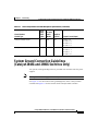
System Ground Connection Guidelines (Catalyst 2948G and 2980G Switches
Only) 2-3
Connecting the Switch to Earth Ground 2-5
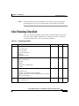
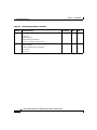
Site-Planning Checklist 2-7
CHAPTER
3
Installing the Switch 3-1
Preparing for Installation 3-2
EMC Regulatory Statements 3-2
U.S.A. 3-2
Taiwan 3-2
VCCI Class A Notice for Japan 3-3
Korea 3-3
Class A Notice for Hungary 3-4
Checking the Shipping Container 3-4
Catalyst 2948G and 2980G Switches 3-4
Catalyst 2948G-GE-TX Switches 3-5
Catalyst 2984G, 2948G-GE-TX, and 2980G Switch Hardware Installation Guide
vi
78-6286-05
Contents
Installing the Catalyst 2948G and 2980G Switches 3-6
Required Installation Tools 3-6
Rack-Mounting the Catalyst 2948G and 2980G Switches 3-7
Installing the Catalyst 2948G-GE-TX Switch 3-9
Rack-Mounting the Catalyst 2948G-GE-TX Switch 3-10
Removing Screws from the Switch 3-10
Attaching Brackets to the Switch 3-11
Mounting the Switch in a Rack 3-14
Attaching the Cable Guide 3-15
Wall-Mounting the Catalyst 2948G-GE-TX Switch 3-16
Attaching the Brackets to the Switch for Wall-Mounting 3-16
Attaching the RPS Connector Cover 3-17
Mounting the Switch on a Wall 3-17
Mounting the Catalyst 2948G-GE-TX Switch on a Table or Shelf 3-19
Connecting Power to the Switches 3-19
Connecting to 10/100 and 10/100/1000 Ports 3-20
Connecting a Terminal to the Console Serial and Ethernet Management
Ports 3-22
Verifying Switch Operation 3-23
CHAPTER
4
Configuring the Gigabit Ethernet Ports 4-1
Installing, Removing, and Maintaining GBICs 4-2
GBIC Features 4-2
Port Cabling Specifications 4-4
GBIC Optical Power Characteristics 4-5
GBIC Cabling Restrictions 4-5
Installing GBICs 4-6
Removing GBICs 4-9
GBIC Maintenance Guidelines 4-10
Catalyst 2984G, 2948G-GE-TX, and 2980G Switch Hardware Installation Guide
78-6286-05
vii
Contents
Patch Cord 4-10
Patch Cord Configuration Example 4-11
Patch Cord Installation 4-11
Connecting To an SFP Module 4-12
CHAPTER
Troubleshooting the Installation 5-1
5
Getting Started 5-2
Problem Solving to the System Component Level 5-2
Identifying Startup Problems 5-3
Troubleshooting the Power Supply 5-4
Contacting Customer Service 5-5
APPENDIX
A
Specifications A-1
Console Serial Port A-1
10BASE-T and 10/100BASE-T Ethernet Management Ports A-2
Catalyst 2948G Switch Specifications A-2
Catalyst 2948G-GE-TX Switch Specifications A-5
Catalyst 2980G Switch Specifications A-6
APPENDIX
B
Repacking a Switch B-1
APPENDIX
C
Differential Mode Delay C-1
APPENDIX
D
Translated Safety Warnings D-1
Warning Definition D-2
Safety Information Referral Warning D-7
Qualified Personnel Warning D-9
Invisible Laser Radiation Warning D-10
Catalyst 2984G, 2948G-GE-TX, and 2980G Switch Hardware Installation Guide
viii
78-6286-05
Contents
Laser Radiation D-11
Attaching the Cisco RPS (model PWR300-AC-RPS-N1) D-13
Attaching the Cisco RPS (model PWR600-AC-RPS) D-14
Attaching the Cisco RPS (model PWR675-AC-RPS-N1) D-15
Redundant Power Supply Connection Warning D-17
Switch Installation Warning D-18
Chassis Warning for Rack-Mounting and Servicing D-20
INDEX
Catalyst 2984G, 2948G-GE-TX, and 2980G Switch Hardware Installation Guide
78-6286-05
ix
Contents
Catalyst 2984G, 2948G-GE-TX, and 2980G Switch Hardware Installation Guide
x
78-6286-05
Cisco Limited Lifetime Hardware
Warranty Terms
There are special terms applicable to your hardware warranty and various services
that you can use during the warranty period. Your formal Warranty Statement,
including the warranty applicable to Cisco software, is included on the Cisco
Documentation CD and on Cisco.com. Follow these steps to access and download
the Cisco Information Packet and your warranty document from the CD or
Cisco.com.
1.
Launch your browser, and go to this URL:
http://www.cisco.com/univercd/cc/td/doc/es_inpck/cetrans.htm
The Warranties and License Agreements page appears.
2.
To read the Cisco Information Packet, follow these steps:
a. Click the Information Packet Number field, and make sure that the part
number 78-5235-02F0 is highlighted.
b. Select the language in which you would like to read the document.
c. Click Go.
The Cisco Limited Warranty and Software License page from the
Information Packet appears.
d. Read the document online, or click the PDF icon to download and print
the document in Adobe Portable Document Format (PDF).
Catalyst 2984G, 2948G-GE-TX, and 2980G Switch Hardware Installation Guide
78-6286-05
xi
Cisco Limited Lifetime Hardware Warranty Terms
Note
3.
You must have Adobe Acrobat Reader to view and print PDF
files. You can download the reader from Adobe’s website:
http://www.adobe.com
To read translated and localized warranty information about your product,
follow these steps:
a. Enter this part number in the Warranty Document Number field:
78-6310-02C0
b. Select the language in which you would like to view the document.
c. Click Go.
The Cisco warranty page appears.
d. Read the document online, or click the PDF icon to download and print
the document in Adobe Portable Document Format (PDF).
You can also contact the Cisco service and support website for assistance:
http://www.cisco.com/public/Support_root.shtml.
Duration of Hardware Warranty
A Cisco product hardware warranty is supported for as long as the original end
user continues to own or use the product, provided that the fan and power supply
warranty is limited to five (5) years. In the event of a discontinuance of product
manufacture, the Cisco warranty support is limited to five (5) years from the
announcement of the discontinuance.
Replacement, Repair, or Refund Policy for Hardware
Cisco or its service center will use commercially reasonable efforts to ship a
replacement part within ten (10) working days after receipt of the Return
Materials Authorization (RMA) request. Actual delivery times can vary,
depending on the customer location.
Cisco reserves the right to refund the purchase price as its exclusive warranty
remedy.
To Receive a Return Materials Authorization (RMA) Number
Contact the company from whom you purchased the product. If you purchased the
product directly from Cisco, contact your Cisco Sales and Service Representative.
Catalyst 2984G, 2948G-GE-TX, and 2980G Switch Hardware Installation Guide
xii
78-6286-05
Cisco Limited Lifetime Hardware Warranty Terms
Complete the information below, and keep it for reference.
Company product purchased from
Company telephone number
Product model number
Product serial number
Maintenance contract number
Catalyst 2984G, 2948G-GE-TX, and 2980G Switch Hardware Installation Guide
78-6286-05
xiii
Cisco Limited Lifetime Hardware Warranty Terms
Catalyst 2984G, 2948G-GE-TX, and 2980G Switch Hardware Installation Guide
xiv
78-6286-05
Preface
This preface describes the audience, organization, and conventions of the
Catalyst 2984G, 2948G-GE-TX, and 2980G Switch Hardware Installation Guide
and provides information on how to obtain related documentation.
Audience
To use this hardware guide, you should be familiar with electronic circuitry and
wiring practices and preferably be an electronic or electromechanical technician.
Organization
This guide is organized as follows:
Chapter
Title
Description
Chapter 1
Product Overview
Lists and describes the hardware features
and functionality of the Catalyst 2948G,
2948G-GE-TX, and 2980G switches.
Chapter 2
Site Planning
Describes how to prepare your site for the
installation of the switch.
Chapter 3
Installing the
Switch
Describes how to install the Catalyst 2948G,
2948G-GE-TX, and 2980G switches.
Provides procedures for removing and
installing chassis components.
Catalyst 2984G, 2948G-GE-TX, and 2980G Switch Hardware Installation Guide
78-6286-05
xv
Preface
Related Documentation
Chapter
Title
Description
Chapter 4
Gigabit Ethernet
Describes the features and configuration of
Port Configuration the Gigabit Ethernet ports.
Chapter 5
Troubleshooting
the Installation
Provides troubleshooting guidelines for the
initial hardware installation and suggests
steps to help isolate and resolve problems.
Appendix A Specifications
Lists Catalyst 2948G and 2980G switch
specifications.
Appendix B Repacking
a Switch
Provides procedures to repack your
Catalyst 2948G or 2980G switch in the event
that you have to return it to the factory.
Appendix C Differential Mode
Delay
Describes the nature and causes of
differential mode delay (DMD) and ways to
prevent it.
Appendix D Translated Safety
Warnings
Repeats in multiple languages the warnings
in this guide.
Related Documentation
Refer to the following documents for additional Catalyst 4500 series information:
•
Software Configuration Guide—Catalyst 4500 Series, Catalyst 2948G, and
Catalyst 2980G Switches
•
Command Reference—Catalyst 4500 Series, Catalyst 2948G, and Catalyst
2980G Switches
•
System Message Guide—Catalyst 4500 Series, Catalyst 2948G, and Catalyst
2980G Switches
Catalyst 2984G, 2948G-GE-TX, and 2980G Switch Hardware Installation Guide
xvi
78-6286-05
Preface
Conventions
Conventions
This document uses the following conventions:
Convention
Description
boldface font
Commands and keywords are in boldface.
italic font
Arguments for which you supply values are in italics.
[ ]
Elements in square brackets are optional.
{x|y|z}
Alternative keywords are grouped in braces and
separated by vertical bars.
[x|y|z]
Optional alternative keywords are grouped in brackets
and separated by vertical bars.
string
A nonquoted set of characters. Do not use quotation
marks around the string or the string will include the
quotation marks.
screen
font
boldface screen
Terminal sessions and information the system displays
are in screen font.
Information you must enter is in boldface
font.
screen
font
italic screen font
Arguments for which you supply values are in italic
font.
screen
^
The symbol ^ represents the key labeled Control—for
example, the key combination ^D in a screen display
means hold down the Control key while you press the D
key.
< >
Nonprinting characters, such as passwords are in angle
brackets.
Notes use the following conventions:
Note
Means reader take note. Notes contain helpful suggestions or references to
material not covered in the publication.
Catalyst 2984G, 2948G-GE-TX, and 2980G Switch Hardware Installation Guide
78-6286-05
xvii
Preface
Conventions
Cautions use the following conventions:
Caution
Means reader be careful. In this situation, you might do something that could
result in equipment damage or loss of data.
Warnings use the following conventions:
Warning
IMPORTANT SAFETY INSTRUCTIONS
This warning symbol means danger. You are in a situation that could cause
bodily injury. Before you work on any equipment, be aware of the hazards
involved with electrical circuitry and be familiar with standard practices for
preventing accidents. Use the statement number provided at the end of each
warning to locate its translation in the translated safety warnings that
accompanied this device. Statement 1071
SAVE THESE INSTRUCTIONS
Waarschuwing
BELANGRIJKE VEILIGHEIDSINSTRUCTIES
Dit waarschuwingssymbool betekent gevaar. U verkeert in een situatie die
lichamelijk letsel kan veroorzaken. Voordat u aan enige apparatuur gaat
werken, dient u zich bewust te zijn van de bij elektrische schakelingen
betrokken risico's en dient u op de hoogte te zijn van de standaard praktijken
om ongelukken te voorkomen. Gebruik het nummer van de verklaring
onderaan de waarschuwing als u een vertaling van de waarschuwing die bij
het apparaat wordt geleverd, wilt raadplegen.
BEWAAR DEZE INSTRUCTIES
Catalyst 2984G, 2948G-GE-TX, and 2980G Switch Hardware Installation Guide
xviii
78-6286-05
Preface
Conventions
Varoitus
TÄRKEITÄ TURVALLISUUSOHJEITA
Tämä varoitusmerkki merkitsee vaaraa. Tilanne voi aiheuttaa ruumiillisia
vammoja. Ennen kuin käsittelet laitteistoa, huomioi sähköpiirien
käsittelemiseen liittyvät riskit ja tutustu onnettomuuksien yleisiin
ehkäisytapoihin. Turvallisuusvaroitusten käännökset löytyvät laitteen
mukana toimitettujen käännettyjen turvallisuusvaroitusten joukosta
varoitusten lopussa näkyvien lausuntonumeroiden avulla.
SÄILYTÄ NÄMÄ OHJEET
Attention
IMPORTANTES INFORMATIONS DE SÉCURITÉ
Ce symbole d'avertissement indique un danger. Vous vous trouvez dans une
situation pouvant entraîner des blessures ou des dommages corporels. Avant
de travailler sur un équipement, soyez conscient des dangers liés aux circuits
électriques et familiarisez-vous avec les procédures couramment utilisées
pour éviter les accidents. Pour prendre connaissance des traductions des
avertissements figurant dans les consignes de sécurité traduites qui
accompagnent cet appareil, référez-vous au numéro de l'instruction situé à la
fin de chaque avertissement.
CONSERVEZ CES INFORMATIONS
Warnung
WICHTIGE SICHERHEITSHINWEISE
Dieses Warnsymbol bedeutet Gefahr. Sie befinden sich in einer Situation, die
zu Verletzungen führen kann. Machen Sie sich vor der Arbeit mit Geräten mit
den Gefahren elektrischer Schaltungen und den üblichen Verfahren zur
Vorbeugung vor Unfällen vertraut. Suchen Sie mit der am Ende jeder Warnung
angegebenen Anweisungsnummer nach der jeweiligen Übersetzung in den
übersetzten Sicherheitshinweisen, die zusammen mit diesem Gerät
ausgeliefert wurden.
BEWAHREN SIE DIESE HINWEISE GUT AUF.
Catalyst 2984G, 2948G-GE-TX, and 2980G Switch Hardware Installation Guide
78-6286-05
xix
Preface
Conventions
Avvertenza
IMPORTANTI ISTRUZIONI SULLA SICUREZZA
Questo simbolo di avvertenza indica un pericolo. La situazione potrebbe
causare infortuni alle persone. Prima di intervenire su qualsiasi
apparecchiatura, occorre essere al corrente dei pericoli relativi ai circuiti
elettrici e conoscere le procedure standard per la prevenzione di incidenti.
Utilizzare il numero di istruzione presente alla fine di ciascuna avvertenza
per individuare le traduzioni delle avvertenze riportate in questo documento.
CONSERVARE QUESTE ISTRUZIONI
Advarsel
VIKTIGE SIKKERHETSINSTRUKSJONER
Dette advarselssymbolet betyr fare. Du er i en situasjon som kan føre til skade
på person. Før du begynner å arbeide med noe av utstyret, må du være
oppmerksom på farene forbundet med elektriske kretser, og kjenne til
standardprosedyrer for å forhindre ulykker. Bruk nummeret i slutten av hver
advarsel for å finne oversettelsen i de oversatte sikkerhetsadvarslene som
fulgte med denne enheten.
TA VARE PÅ DISSE INSTRUKSJONENE
Aviso
INSTRUÇÕES IMPORTANTES DE SEGURANÇA
Este símbolo de aviso significa perigo. Você está em uma situação que poderá
ser causadora de lesões corporais. Antes de iniciar a utilização de qualquer
equipamento, tenha conhecimento dos perigos envolvidos no manuseio de
circuitos elétricos e familiarize-se com as práticas habituais de prevenção de
acidentes. Utilize o número da instrução fornecido ao final de cada aviso para
localizar sua tradução nos avisos de segurança traduzidos que acompanham
este dispositivo.
GUARDE ESTAS INSTRUÇÕES
Catalyst 2984G, 2948G-GE-TX, and 2980G Switch Hardware Installation Guide
xx
78-6286-05
Preface
Conventions
¡Advertencia!
INSTRUCCIONES IMPORTANTES DE SEGURIDAD
Este símbolo de aviso indica peligro. Existe riesgo para su integridad física.
Antes de manipular cualquier equipo, considere los riesgos de la corriente
eléctrica y familiarícese con los procedimientos estándar de prevención de
accidentes. Al final de cada advertencia encontrará el número que le ayudará
a encontrar el texto traducido en el apartado de traducciones que acompaña
a este dispositivo.
GUARDE ESTAS INSTRUCCIONES
Varning!
VIKTIGA SÄKERHETSANVISNINGAR
Denna varningssignal signalerar fara. Du befinner dig i en situation som kan
leda till personskada. Innan du utför arbete på någon utrustning måste du vara
medveten om farorna med elkretsar och känna till vanliga förfaranden för att
förebygga olyckor. Använd det nummer som finns i slutet av varje varning för
att hitta dess översättning i de översatta säkerhetsvarningar som medföljer
denna anordning.
SPARA DESSA ANVISNINGAR
Catalyst 2984G, 2948G-GE-TX, and 2980G Switch Hardware Installation Guide
78-6286-05
xxi
Preface
Conventions
Catalyst 2984G, 2948G-GE-TX, and 2980G Switch Hardware Installation Guide
xxii
78-6286-05
Preface
Obtaining Documentation
Obtaining Documentation
Cisco provides several ways to obtain documentation, technical assistance, and
other technical resources. These sections explain how to obtain technical
information from Cisco Systems.
Cisco.com
You can access the most current Cisco documentation on the World Wide Web at
this URL:
http://www.cisco.com/univercd/home/home.htm
You can access the Cisco website at this URL:
http://www.cisco.com
International Cisco websites can be accessed from this URL:
http://www.cisco.com/public/countries_languages.shtml
Documentation CD-ROM
Cisco documentation and additional literature are available in a Cisco
Documentation CD-ROM package, which may have shipped with your product.
The Documentation CD-ROM is updated regularly and may be more current than
printed documentation. The CD-ROM package is available as a single unit or
through an annual or quarterly subscription.
Registered Cisco.com users can order a single Documentation CD-ROM (product
number DOC-CONDOCCD=) through the Cisco Ordering tool:
http://www.cisco.com/en/US/partner/ordering/ordering_place_order_ordering_t
ool_launch.html
All users can order annual or quarterly subscriptions through the online
Subscription Store:
http://www.cisco.com/go/subscription
Catalyst 2984G, 2948G-GE-TX, and 2980G Switch Hardware Installation Guide
78-6286-05
xxiii
Preface
Obtaining Technical Assistance
Ordering Documentation
You can find instructions for ordering documentation at this URL:
http://www.cisco.com/univercd/cc/td/doc/es_inpck/pdi.htm
You can order Cisco documentation in these ways:
•
Registered Cisco.com users (Cisco direct customers) can order Cisco product
documentation from the Networking Products MarketPlace:
http://www.cisco.com/en/US/partner/ordering/index.shtml
•
Nonregistered Cisco.com users can order documentation through a local
account representative by calling Cisco Systems Corporate Headquarters
(California, USA.) at 408 526-7208 or, elsewhere in North America, by
calling 800 553-NETS (6387).
Documentation Feedback
You can submit comments electronically on Cisco.com. On the Cisco
Documentation home page, click Feedback at the top of the page.
You can send your comments in e-mail to [email protected].
You can submit comments by using the response card (if present) behind the front
cover of your document or by writing to the following address:
Cisco Systems
Attn: Customer Document Ordering
170 West Tasman Drive
San Jose, CA 95134-9883
We appreciate your comments.
Obtaining Technical Assistance
For all customers, partners, resellers, and distributors who hold valid Cisco
service contracts, the Cisco Technical Assistance Center (TAC) provides 24-hour,
award-winning technical support services, online and over the phone. Cisco.com
features the Cisco TAC website as an online starting point for technical assistance.
Catalyst 2984G, 2948G-GE-TX, and 2980G Switch Hardware Installation Guide
xxiv
78-6286-05
Preface
Obtaining Technical Assistance
Cisco TAC Website
The Cisco TAC website (http://www.cisco.com/tac) provides online documents
and tools for troubleshooting and resolving technical issues with Cisco products
and technologies. The Cisco TAC website is available 24 hours a day, 365 days a
year.
Accessing all the tools on the Cisco TAC website requires a Cisco.com user ID
and password. If you have a valid service contract but do not have a login ID or
password, register at this URL:
http://tools.cisco.com/RPF/register/register.do
Opening a TAC Case
The online TAC Case Open Tool (http://www.cisco.com/tac/caseopen) is the
fastest way to open P3 and P4 cases. (Your network is minimally impaired or you
require product information). After you describe your situation, the TAC Case
Open Tool automatically recommends resources for an immediate solution. If
your issue is not resolved using these recommendations, your case will be
assigned to a Cisco TAC engineer.
For P1 or P2 cases (your production network is down or severely degraded) or if
you do not have Internet access, contact Cisco TAC by telephone. Cisco TAC
engineers are assigned immediately to P1 and P2 cases to help keep your business
operations running smoothly.
To open a case by telephone, use one of the following numbers:
Asia-Pacific: +61 2 8446 7411 (Australia: 1 800 805 227)
EMEA: +32 2 704 55 55
USA: 1 800 553-2447
For a complete listing of Cisco TAC contacts, go to this URL:
http://www.cisco.com/warp/public/687/Directory/DirTAC.shtml
TAC Case Priority Definitions
To ensure that all cases are reported in a standard format, Cisco has established
case priority definitions.
Catalyst 2984G, 2948G-GE-TX, and 2980G Switch Hardware Installation Guide
78-6286-05
xxv
Preface
Obtaining Additional Publications and Information
Priority 1 (P1)—Your network is “down” or there is a critical impact to your
business operations. You and Cisco will commit all necessary resources around
the clock to resolve the situation.
Priority 2 (P2)—Operation of an existing network is severely degraded, or
significant aspects of your business operation are negatively affected by
inadequate performance of Cisco products. You and Cisco will commit full-time
resources during normal business hours to resolve the situation.
Priority 3 (P3)—Operational performance of your network is impaired, but most
business operations remain functional. You and Cisco will commit resources
during normal business hours to restore service to satisfactory levels.
Priority 4 (P4)—You require information or assistance with Cisco product
capabilities, installation, or configuration. There is little or no effect on your
business operations.
Obtaining Additional Publications and Information
Information about Cisco products, technologies, and network solutions is
available from various online and printed sources.
•
The Cisco Product Catalog describes the networking products offered by
Cisco Systems, as well as ordering and customer support services. Access the
Cisco Product Catalog at this URL:
http://www.cisco.com/en/US/products/products_catalog_links_launch.html
•
Cisco Press publishes a wide range of networking publications. Cisco
suggests these titles for new and experienced users: Internetworking Terms
and Acronyms Dictionary, Internetworking Technology Handbook,
Internetworking Troubleshooting Guide, and the Internetworking Design
Guide. For current Cisco Press titles and other information, go to Cisco Press
online at this URL:
http://www.ciscopress.com
Catalyst 2984G, 2948G-GE-TX, and 2980G Switch Hardware Installation Guide
xxvi
78-6286-05
Preface
Obtaining Additional Publications and Information
•
Packet magazine is the Cisco quarterly publication that provides the latest
networking trends, technology breakthroughs, and Cisco products and
solutions to help industry professionals get the most from their networking
investment. Included are networking deployment and troubleshooting tips,
configuration examples, customer case studies, tutorials and training,
certification information, and links to numerous in-depth online resources.
You can access Packet magazine at this URL:
http://www.cisco.com/go/packet
•
iQ Magazine is the Cisco bimonthly publication that delivers the latest
information about Internet business strategies for executives. You can access
iQ Magazine at this URL:
http://www.cisco.com/go/iqmagazine
•
Internet Protocol Journal is a quarterly journal published by Cisco Systems
for engineering professionals involved in designing, developing, and
operating public and private internets and intranets. You can access the
Internet Protocol Journal at this URL:
http://www.cisco.com/en/US/about/ac123/ac147/about_cisco_the_internet_
protocol_journal.html
•
Training—Cisco offers world-class networking training. Current offerings in
network training are listed at this URL:
http://www.cisco.com/en/US/learning/index.html
Catalyst 2984G, 2948G-GE-TX, and 2980G Switch Hardware Installation Guide
78-6286-05
xxvii
Preface
Obtaining Additional Publications and Information
Catalyst 2984G, 2948G-GE-TX, and 2980G Switch Hardware Installation Guide
xxviii
78-6286-05
C H A P T E R
1
Product Overview
This chapter provides an overview of the features and components of the
Catalyst 2948G, 2948G-GE-TX, and 2980G switches. It contains these sections:
Note
•
Switch Description, page 1
•
Switch Components, page 7
Throughout this guide, Catalyst 2980G switch refers to both the Catalyst 2980G
switch and the Catalyst 2980G-A switch, unless otherwise noted.
Switch Description
The Catalyst 2948G, 2948G-GE-TX, and 2980G switches are designed for
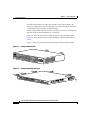
high-performance, high-density wiring-closet applications. Figure 1-1 through
Figure 1-3 show the switches.
Catalyst 2984G, 2948G-GE-TX, and 2980G Switch Hardware Installation Guide
78-6286-05
1-1
Chapter 1
Product Overview
Switch Description
Catalyst 2948G Switch
98431
Figure 1-1
STATUS
Catalyst
2948G
CONSOL
E
1000Base
-X
10BaseT
Catalyst 2948G-GE-TX Switch
Figure 1-3
Catalyst 2980G Switch
98434
Figure 1-2
1
SLOT
1
2
3
1
4
5
6
7
8
9
10
11
12
13
14
15
10/100/100
0 ETHE
RENE
T
18
19
20
21
2
1
2
3
4
5
6
7
8
9
2
16
17
STATUS
22
23
24
25
26
CATALY
27
28
47
29
30
31
11
12
13
14
15
33
34
35
36
16
17
18
19
20
21
22
23
37
38
39
40
41
42
43
44
48
45
24
SLOT25 26
3
27
28
29
31
46
47
48
CONSOLE
32
30
ST 298
6
32
31
10
50747
2
10MB
MGT
32
33
RESE
T
34
PWR
The Catalyst 2948G, 2948G-GE-TX, and 2980G switches interface with
networking equipment using Ethernet (10BASE-T), Fast Ethernet (100BASE-T),
and Gigabit Ethernet (1000BASE-T) interfaces. Depending on the model, the
switches also support Gigabit Interface Converters (GBICs) or small form-factor
pluggable (SFP) modules.
Catalyst 2984G, 2948G-GE-TX, and 2980G Switch Hardware Installation Guide
1-2
78-6286-05
Chapter 1
Product Overview
Switch Description
The Catalyst 2948G switch has 48 autosensing and autoconfiguring
10/100BASE-T Fast Ethernet fixed ports. The Catalyst 2948G-GE-TX switch has
48 autosensing and autoconfiguring 10/100/1000BASE-T ports. The
Catalyst 2980G switch has 80 autosensing and autoconfiguring 10/100BASE-T
Fast Ethernet fixed ports.
GBIC Module Support
The Catalyst 2948G and 2980G switches each have two Gigabit Ethernet uplink
ports with modular Gigabit Interface Converters (GBICs).
A GBIC is a hot-swappable input/output device that plugs into a Gigabit Ethernet
port module and links the port module with a fiber-optic network. For a detailed
description of Gigabit Ethernet ports, see the “GBIC Features” section on
page 4-2.
For a complete list of supported GBIC modules, see Table 4-1 on page 4-3.
Note
The Catalyst 2948G-GE-TX switch does not support GBIC modules.
The Gigabit Ethernet ports can be configured with any combination of GBIC
types.
The Gigabit Ethernet ports on these modules are used primarily for backbone
interconnection of other high-performance switches and routers.
SFP Module Support
The Catalyst 2948G-GE-TX switch has four small form-factor pluggable (SFP)
module slots. The switch uses SFP modules to establish Gigabit connections. The
SFP module slots are located on the front of the switch.
An SFP module is a hot-swappable input/output device that plugs into an SFP
module slot, linking the port module with a fiber-optic network.
For a list of SFP modules supported by the Catalyst 2948G-GE-TX switch, see
Table 4-4 on page 4-12.
Catalyst 2984G, 2948G-GE-TX, and 2980G Switch Hardware Installation Guide
78-6286-05
1-3
Chapter 1
Product Overview
Switch Description
Note
Catalyst 2948G-GE-TX switch only supports 1000 Mbps and full-duplex modes
on SFP modules.
Except for the 1000BASE-T SFP module, all of the SFP modules are used to
establish fiber-optic connections. You use fiber-optic cables with Lucent (LC)
connectors to connect to an SFP module. The SFP modules support 850 to 1550
nanometer nominal wave lengths. These field-replaceable modules provide the
uplink optical interfaces, laser send (TX) and laser receive (RX). For a detailed
description of Gigabit Ethernet ports see the “Connecting To an SFP Module”
section on page 4-12.
Switch Features
Table 1-1 describes the Catalyst 2948G, 2948G-GE-TX, and 2980G switch
features.
Table 1-1
Catalyst 2948G, 2948G-GE-TX, and 2980G Switch Features
Feature
Description
Ethernet speeds
•
Ethernet (10BASE-T) interface to workstations and repeaters
•
Fast Ethernet (100BASE-T) interface to workstations, servers,
switches, and routers
Note
Standard management and
support
Autonegotiation of link speed on each 10/100 and 10/100/1000
port allows migration to 100BASE-T or 1000BASE-T from a
10BASE-T or 100BASE-T installed base.
•
Gigabit Ethernet (1000BASE-T) copper and Gigabit Ethernet
(1000BASE-X) fiber-optic interface for backbone interconnection of
high-performance switches and routers
•
Layer 2 forwarding with an aggregate forwarding rate of greater than
17.8 million packets per second
•
16,000 MAC addresses per system
Catalyst 2984G, 2948G-GE-TX, and 2980G Switch Hardware Installation Guide
1-4
78-6286-05
Chapter 1
Product Overview
Switch Description
Table 1-1
Catalyst 2948G, 2948G-GE-TX, and 2980G Switch Features (continued)
Feature
Standard management and
support (continued)
Software management
Description
•
Up to 1,024 VLANs with IEEE 802.1Q VLAN tagging on all ports
and support for VTP1
•
Port aggregation using PAgP2 for 100-Mbps and 1-Gbps
EtherChannel
•
CLI3 and SNMP interfaces consistent with the Catalyst 4500 series
and 6500 family switches
•
Development of new features compatible with the Catalyst 6500
family switches
•
Out-of-band management through the RJ-45 10BASE-T console
serial port
•
10BASE-T out-of-band management and in-band management
through any switch port with SNMP, Telnet client, and TFTP
Note
The Catalyst 2948G-GE-TX and 2980G-A switches have a
10/100BASE-T management port.
•
RMON4 with RMON 1
•
Standard Layer 2 elements:
– 802.1D Spanning Tree
– CDP5
– VTP6 version 2 with pruning extensions
– CGMP7 client
Catalyst 2984G, 2948G-GE-TX, and 2980G Switch Hardware Installation Guide
78-6286-05
1-5
Chapter 1
Product Overview
Switch Description
Table 1-1
Catalyst 2948G, 2948G-GE-TX, and 2980G Switch Features (continued)
Feature
Description
Embedded management
Power supplies
•
Full SNMP implementation, including entity-MIB, all relevant
standard MIBs, and all relevant Cisco MIBs
•
The first four RMON groups (Ethernet statistics, Alarms, Events, and
History) supported on a per port basis without an optional RMON
processing module
•
Redirection of traffic from any port to a “sniff” port. (Any switching
port can be designated as a “sniff” port.)
•
Performance management information
•
120 W AC internal power supply on the Catalyst 2948G switch
•
156 W AC internal power supply on the Catalyst 2948G-GE-TX
switch
•
175 W AC internal power supply on the Catalyst 2980G switch
1. VTP = VLAN Trunking Protocol
2. PAgP = Port Aggregation Protocol
3. CLI = command-line interface
4. RMON = Remote Monitoring
5. CDP = Cisco Discovery Protocol
6. VTP = Virtual Terminal Protocol
7. CGMP = Cisco Group Management Protocol
Port Locations
This section describes the port locations and numbering on the switches.
10/100 and 10/100/1000 Ports
The 10/100 and 10/100/1000 ports are configured in vertical pairs. Each vertical
pair has two Link Status LEDs below it. The LED on the left is for the top port;
the LED on the right is for the bottom port. For example, LED 1 is for the upper
port (port 1) and LED 2 is for the bottom port (port 2).
Catalyst 2984G, 2948G-GE-TX, and 2980G Switch Hardware Installation Guide
1-6
78-6286-05
Chapter 1
Product Overview
Switch Components
Catalyst 2948G and 2980G Switch Ports
The Catalyst 2948G switch 10/100BASE-T ports are configured in two rows. The
top row contains odd-numbered ports (1 through 47), and the bottom row contains
even-numbered ports (2 through 48).
The Catalyst 2980G switch 10/100BASE-T ports are configured in four rows. The
top two rows are numbered 1 through 48, with the first row odd-numbered (1
through 47) and the second row even-numbered (2 through 48). The bottom two
rows are numbered 1 through 32, with the first row odd-numbered (1 through 31)
and the second row even-numbered (2 through 32).
Two GBIC ports are at the right of the front panel on the Catalyst 2948G and
Catalyst 2980G switches:
•
On the Catalyst 2948G switches, these ports are located at the far right of the
front panel. The upper Gigabit Ethernet port is port 49; the lower is port 50.
The Link Status LEDs for these ports are below port 50.
•
On the Catalyst 2980G switches, the GBIC Ethernet ports are located
immediately to the right of ports 31 and 32. The port on the left is port 33; the
port on the right is port 34. The Link Status LEDs for the Gigabit Ethernet
ports are located below each port.
Catalyst 2948G-GE-TX Switch Ports
The Catalyst 2948G-GE-TX 10/100/1000BASE-T Gigabit Ethernet ports are
configured in two rows. The top row contains odd-numbered ports (1 through 47),
and the bottom row contains even-numbered ports (2 through 48).
The SFP module slots are numbered left to right 49 through 52.
Switch Components
This section describes the following Catalyst 2948G and 2980G switch
components:
•
Management Ports, page 8
•
Front Panel LEDs, page 8
Catalyst 2984G, 2948G-GE-TX, and 2980G Switch Hardware Installation Guide
78-6286-05
1-7
Chapter 1
Product Overview
Switch Components
•
Airflow, page 9
•
Power Supplies, page 11
Management Ports
The Catalyst 2948G, 2948G-GE-TX, and 2980G switches have two kinds of
management ports: console serial and Ethernet. The Catalyst 2948G switches
have a 10BASE-T management port. The Catalyst 2948G-GE-TX and 2980G-A
switches have a 10/100BASE-T management port.
Table 1-2 on page 1-9 lists the management options for the switches.
Console Serial Port
An RJ-45 console serial port allows you to perform switch-management functions
using a terminal. See Table A-1 on page A-1 for the console connector pinouts.
10BASE-T and 10/100BASE-T Ports
An RJ-45 10BASE-T port allows you to perform TCP/IP switch-management
functions (Telnet, SNMP, FTP), configure IP addresses with BOOTP, and
download software images.
Note
The Catalyst 2948G-GE-TX and 2980G-A switches have a 10/100BASE-T
management port.
This port is for network management only; it is not for switching. Connectivity is
not available between this port and the 10/100BASE-T switching ports.
Front Panel LEDs
The LEDs on the front panels of the Catalyst 2948G, 2948G-GE-TX, and 2980G
switches perform the following functions:
•
STATUS LEDs indicate the operating state of the switches.
•
Link Status LEDs provide management and indicate switching port status.
Catalyst 2984G, 2948G-GE-TX, and 2980G Switch Hardware Installation Guide
1-8
78-6286-05
Chapter 1
Product Overview
Switch Components
•
PSI LED indicates the internal power supply status on the Catalyst 2948G
switch.
•
PWR LED indicates the internal power supply status on the Catalyst 2980G
switch.
•
RPS LED provides the external redundant power supply status.
Table 1-2 describes the LEDs.
Table 1-2
Front Panel LEDs
LED
Color/Statue
STATUS
Description
Indicates the results of a series of self-test diagnostics.
Green
Red
Amber
Off
Link Status
All tests pass.
A test other than an individual port test fails.
System boot or diagnostic tests in progress.
Switch is disabled.
Indicates the link status of a port.
Green
Amber
Flashing
Off
PSI, PWR, and RPS
Port is operational.
Port is disabled by user.
Power-on self-test indicates faulty port.
No signal detected, or link configuration failure.
Indicates power supply operation or failure.
Green
Amber
Power supply is operational.
Power supply has failed or is in Standby mode.
Airflow
Note
For environmental specifications, see Chapter 2, “Site Planning.”
On the Catalyst 2948G and 2980G switches, the system fan assembly provides
cooling air for the internal chassis components. The fans exhaust warm air from
one end and draw in cool air at the other end.
Catalyst 2984G, 2948G-GE-TX, and 2980G Switch Hardware Installation Guide
78-6286-05
1-9
Chapter 1
Product Overview
Switch Components
If an individual fan fails, the other fans continue to run. Sensors monitor the
internal air temperatures. If the air temperature exceeds a tolerable threshold, the
environmental monitor displays warning messages.
On the Catalyst 2948G-GE-TX, a blower system draws cool air in from the front
and sides of the switch and exhausts air out the back.
Figure 1-4 shows the direction of airflow through the Catalyst 2948G switch.
Figure 1-5 shows the direction of airflow through the Catalyst 2948G-GE-TX
switch.
Figure 1-6 shows the direction of airflow through the Catalyst 2980G switch.
Catalyst 2948G Airflow
STATUS
Catalyst
2948G
CONSOL
E
1000Base
-X
98432
Figure 1-4
10BaseT
Catalyst 2948G-GE-TX Airflow
98720
Figure 1-5
Catalyst 2984G, 2948G-GE-TX, and 2980G Switch Hardware Installation Guide
1-10
78-6286-05
Chapter 1
Product Overview
Switch Components
Figure 1-6
Catalyst 2980G Airflow
1
SLOT
1
2
3
1
4
5
6
7
8
9
10
11
12
13
14
15
10/100/100
0 ETHE
RENE
T
18
19
20
21
2
1
2
3
4
5
6
7
8
9
2
16
17
STATUS
22
23
24
25
26
CATALY
27
28
47
29
30
31
11
12
13
14
15
33
34
35
36
16
17
18
19
20
21
22
23
37
38
39
40
41
42
43
44
48
45
24
SLOT25 26
3
27
28
29
31
46
47
48
CONSOLE
32
30
ST 298
6
32
31
10
32064
2
10MB
MGT
32
33
RESE
T
34
PWR
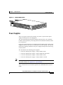
Power Supplies
There is no power switch on the switches. AC power is present in the power
supply when the power cord is plugged in.
The environmental monitoring and reporting functions allow you to maintain
normal system operation by correcting adverse environmental conditions before
loss of operation.
Each power supply monitors its own temperature and output voltages. If the power
supply becomes excessively hot, it shuts down to prevent damage. The switches
monitor the operating condition of the power supply and report the status using
switch software.
The switches have the following power supplies:
Note
•
120 W AC internal power supply—Catalyst 2948G switch
•
156 W AC internal power supply—Catalyst 2948G-GE-TX switch
•
175 W AC internal power supply—Catalyst 2980G switch
•
156 W AC internal power supply—Catalyst 2980G-A switch
For complete power specifications for the Catalyst 2948G, 2948G-GE-TX,
and 2980G switches, see Appendix A, “Specifications.”
These switches also be used with an optional Cisco Redundant Power System
(RPS).
Catalyst 2984G, 2948G-GE-TX, and 2980G Switch Hardware Installation Guide
78-6286-05
1-11
Chapter 1
Product Overview
Switch Components
•
The Catalyst 2948G switch uses the Cisco RPS 600 AC power supply
(PWR600-AC-RPS-CAB).
The Cisco RPS 600 supports four external devices that use up to 150 W DC
each. Use a one-to-one cable (one connector at each cable end) to connect
four external devices to the four DC output power modules.
The power source is partially redundant. There are two AC input power
modules for the Cisco RPS and one DC output power module for each
external device. The AC input to the Cisco RPS is fully redundant, but the DC
output to the external devices is not.
Warning
Attach only the Cisco RPS (model PWR600-AC-RPS) to the RPS receptacle.
Statement 112
•
The Catalyst 2948G-GE-TX switch uses the Cisco RPS 675 (model
PWR675-AC-RPS-N1).
The RPS 675 supports six external network devices and provides DC power
to one failed device at a time. It automatically senses when the internal power
supply of a connected device fails and provides power to that device, which
prevents loss of network traffic.
Warning
Attach only the Cisco RPS (model PWR675-AC-RPS-N1=) to the RPS receptacle.
Statement 100C
•
The Catalyst 2980G-A switch uses the Cisco RPS 300
(PWR300-AC-RPS-N1).
The RPS 300 supports six external network devices and provides power to
one failed device at a time. It automatically senses when the power supply of
a connected device fails and provides the necessary power to the failed device
to prevent loss of network traffic. When the internal power supply of the
device has been brought up or replaced, the RPS automatically stops
powering the device.
Warning
Attach only the Cisco RPS (model PWR300-AC-RPS-N1) to the RPS receptacle.
Statement 100B
Catalyst 2984G, 2948G-GE-TX, and 2980G Switch Hardware Installation Guide
1-12
78-6286-05
Chapter 1
Product Overview
Switch Components
A Cisco RPS can only power one switch at a time. If more than one switch fails
at the same time, any subsequent switch is not supported by the RPS until the first
switch failure is resolved. For more information, refer to the documentation that
was included with your RPS.
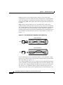
On the Catalyst 2948G switch, you must use a Y cable to connect the switch to
two RPS 600 power supplies. Each RPS 600 has status LEDs (PSI and RPS).
On the Catalyst 2980G-A switch, each RPS 300 power supply has an individual
power cord and has status LEDs (PSI, PWR, and RPS).
The RPS uses redundant power supplies. If one of the power supplies in the RPS
fails, the RPS will automatically switch over to the other power supply without
forcing the switch to reboot.
Note
On the Catalyst 2948G-GE-TX and 2948G switches, only one power source can
supply power to the switch at any one time. When you are using an RPS, unplug
the local power cord for the switch. If you are using the local power supply, the
RPS can be connected but must not be powered on. The switches can be powered
by both the internal power supply and the RPS at the same time.
Catalyst 2984G, 2948G-GE-TX, and 2980G Switch Hardware Installation Guide
78-6286-05
1-13
Chapter 1
Product Overview
Switch Components
Catalyst 2984G, 2948G-GE-TX, and 2980G Switch Hardware Installation Guide
1-14
78-6286-05
C H A P T E R
2
Site Planning
Warning
Before you install, operate, or service the system, read the Site Preparation and
Safety Guide. This guide contains important safety information you should know
before working with the system. Statement 200
Warning
Only trained and qualified personnel should be allowed to install, replace, or
service this equipment. Statement 1030
This chapter describes how to prepare your site for the installation of your switch
and contains these sections:
Note
•
Site Power Requirements and Heat Dissipation, page 2
•
System Ground Connection Guidelines (Catalyst 2948G and 2980G Switches
Only), page 3
•
Site-Planning Checklist, page 7
See the “Site-Planning Checklist” section on page 7 to help ensure that you
complete all site-planning activities before you install the switch.
Catalyst 2984G, 2948G-GE-TX, and 2980G Switch Hardware Installation Guide
78-6286-05
2-1
Chapter 2
Site Planning
Site Power Requirements and Heat Dissipation
Site Power Requirements and Heat Dissipation
Note
Catalyst 2948G, 2948G-GE-TX, and 2980G switches have internal power
supplies. All of the switches support Cisco Redundant Power System (RPS) for
redundant operation.
This section provides site power requirements and heat dissipation specifications
for the Catalyst 2948G, 2948G-GE-TX, and 2980G switches. You should verify
site power before you install a switch.
Power requirements can vary for each Catalyst switch. Knowing the power
requirements can be useful for planning the power distribution system needed to
support the switches. Heat specifications are used for determining the
air-conditioning requirements for an installation.
Note
Refer to the Site Preparation and Safety Guide for site power requirements,
preinstallation requirements, and EMI recommendations.
Table 2-1 describes the power requirements and heat dissipation specifications for
the Catalyst 2948G, 2948G-GE-TX, and 2980G switches.
Table 2-1
Power Requirements and Heat Dissipation Specifications
Model Number/
Module Type
Power
Supply
Output
(Watts)
AC Input
Power
Heat Diss
(Watts)
(BTU/Hr)
Catalyst 2948G switch
120
200
645
90 VAC: 2.0
120 VAC: 1.6
180 VAC: 1.0
240 VAC: 0.9
Catalyst 2948G-GE-TX switch
156
130
445
100 VAC: 1.5
240 VAC: 0.8
AC Input Current (Amps)
Catalyst 2984G, 2948G-GE-TX, and 2980G Switch Hardware Installation Guide
2-2
78-6286-05
Chapter 2
Site Planning
System Ground Connection Guidelines (Catalyst 2948G and 2980G Switches Only)
Table 2-1
Power Requirements and Heat Dissipation Specifications (continued)
Model Number/
Module Type
Power
Supply
Output
(Watts)
AC Input
Power
Heat Diss
(Watts)
(BTU/Hr)
Catalyst 2980G switch
175
300
950
90 VAC: 3.0
120 VAC: 2.4
180 VAC: 1.6
240 VAC: 1.0
Catalyst 2980G-A switch
156
208
670
90 VAC: 2.3
120 VAC: 1.7
180 VAC: 1.1
240 VAC: 0.9
AC Input Current (Amps)
System Ground Connection Guidelines
(Catalyst 2948G and 2980G Switches Only)
Two system (earth) grounding holes are provided in an enclosure near the power
supplies.
Note
These guidelines do not apply to the Catalyst 2948G-GE-TX switches.
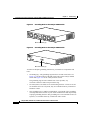
See Figure 2-1 for the location of the grounding holes on the Catalyst 2948G
switches and Figure 2-2 for the location on the Catalyst 2980G switches.
Catalyst 2984G, 2948G-GE-TX, and 2980G Switch Hardware Installation Guide
78-6286-05
2-3
Chapter 2
Site Planning
System Ground Connection Guidelines (Catalyst 2948G and 2980G Switches Only)
Grounding Holes on the Catalyst 2948G Switch
33110
Figure 2-1
M4 screw holes (2)
Grounding Holes on the Catalyst 2980G Switch
33109
Figure 2-2
M4 screw holes (2)
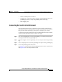
To make an adequate grounding connection, you need these components and
tools:
•
Grounding lug—The grounding lug must have two M4 screw holes. See
Figure 2-1 for the location of the M4 screw holes on the Catalyst 2948G
switch and Figure 2-2 for the Catalyst 2980G switch.
The grounding lugs are not available from Cisco Systems; any
electrical-connector vendor can provide this lug.
•
Two M4 (metric) hex-head screws with locking washers—These screws are
not available from Cisco Systems; they are available from any commercial
hardware vendor.
•
One grounding wire (6 AWG recommended)—The length of the grounding
wires depends on the location of your switch within the site and its proximity
to proper grounding facilities. The grounding wire is not available from Cisco
Systems; it is available from any commercial cable vendor.
Catalyst 2984G, 2948G-GE-TX, and 2980G Switch Hardware Installation Guide
2-4
78-6286-05
Chapter 2
Site Planning
System Ground Connection Guidelines (Catalyst 2948G and 2980G Switches Only)
•
Number 2 Phillips head screwdriver.
•
Crimping tool—This must be large enough to accommodate the girth of the
grounding lug when you crimp the grounding cable into the lug.
•
Wire-stripping tool.
Connecting the Switch to Earth Ground
This procedure describes how to connect the Catalyst 2948G, 2948G-GE-TX,
and 2980G switches to earth ground. We strongly recommend that you complete
this procedure before connecting system power or turning on your switch.
To attach the grounding lug and cable to the grounding pad on the Catalyst 2948G,
2948G-GE-TX, and 2980G switches, follow these steps:
Step 1
Use a wire-stripping tool to remove approximately 0.75 inches (19 mm) of the
covering from the end of the grounding wire.
Step 2
Insert the stripped end of the grounding wire into the open end of the grounding
lug.
Step 3
Use the crimping tool to secure the grounding wire in place in the grounding lug.
Step 4
Locate the grounding pad on the switch.
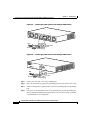
See Figure 2-3 for the location of the grounding pad on the Catalyst 2948G switch
and Figure 2-4 for the Catalyst 2980G switch.
Catalyst 2984G, 2948G-GE-TX, and 2980G Switch Hardware Installation Guide
78-6286-05
2-5
Chapter 2
Site Planning
System Ground Connection Guidelines (Catalyst 2948G and 2980G Switches Only)
Connecting System Ground on the Catalyst 2948G Switch
33112
Figure 2-3
Wire
Screws
Grounding lug
Connecting System Ground on the Catalyst 2980G Switch
33111
Figure 2-4
Grounding
pad
Wire
Screws
Grounding
pad
Grounding lug
Step 5
Remove the label that covers the grounding pad.
Step 6
Place the grounding lug against the grounding pad on the rear panel of the switch.
Step 7
Install locking washers; tighten them to secure the grounding lug to the grounding
pad.
Step 8
Insert two screws through the holes in the grounding lug and the grounding pad.
Ensure that the grounding lug and the attached wire will not interfere with other
switch hardware or rack equipment.
Catalyst 2984G, 2948G-GE-TX, and 2980G Switch Hardware Installation Guide
2-6
78-6286-05
Chapter 2
Site Planning
Site-Planning Checklist
Step 9
Prepare the other end of the grounding wire and connect it to an appropriate
grounding point at your site to ensure adequate earth ground for the switch.
Site-Planning Checklist
Table 2-2 lists the site-planning activities that you should complete before you
install the Catalyst 2948G, 2948G-GE-TX, and 2980G switches. Completing
each activity helps ensure a successful switch installation.
Table 2-2
Site-Planning Checklist
Task No.
Planning Activity
1
Space evaluation:
Verified By
Time
Date
Space and layout
Floor covering
Impact and vibration
Lighting
Maintenance access
2
Environmental evaluation:
Ambient temperature
Humidity
Altitude
Atmospheric contamination
Airflow
3
Power evaluation:
Input power type
Proximity of receptacle to the equipment
Dedicated (separate) circuits for redundant power supplies
UPS for power failures
4
Grounding evaluation:
Circuit breaker size
Catalyst 2984G, 2948G-GE-TX, and 2980G Switch Hardware Installation Guide
78-6286-05
2-7
Chapter 2
Site Planning
Site-Planning Checklist
Table 2-2
Site-Planning Checklist (continued)
Task No.
Planning Activity
5
Cable and interface equipment evaluation:
Verified By
Time
Date
Cable type
Connector type
Cable distance limitations
Interface equipment (transceivers)
6
EMI evaluation:
Distance limitations for signaling
Site wiring
RFI levels
Catalyst 2984G, 2948G-GE-TX, and 2980G Switch Hardware Installation Guide
2-8
78-6286-05
C H A P T E R
3
Installing the Switch
Warning
Before you install, operate, or service the system, read the Site Preparation and
Safety Guide. This guide contains important safety information you should know
before working with the system. Statement 200
Warning
Only trained and qualified personnel should be allowed to install, replace, or
service this equipment. Statement 1030
This chapter describes how to install the Catalyst 2948G, 2948G-GE-TX,
and 2980G switches. For first-time installations, perform the procedures in these
sections in the order listed:
Note
•
Preparing for Installation, page 2
•
Installing the Catalyst 2948G and 2980G Switches, page 6
•
Installing the Catalyst 2948G-GE-TX Switch, page 9
•
Connecting Power to the Switches, page 19
•
Connecting a Terminal to the Console Serial and Ethernet Management Ports,
page 22
Before starting the installation procedures in this chapter, complete the
site-planning checklist in Chapter 2, “Site Planning.”
Catalyst 2984G, 2948G-GE-TX, and 2980G Switch Hardware Installation Guide
78-6286-05
3-1
Chapter 3
Installing the Switch
Preparing for Installation
Preparing for Installation
This section provides information about these topics:
•
EMC Regulatory Statements, page 2
•
Checking the Shipping Container, page 4
EMC Regulatory Statements
This section includes specific regulatory statements about the switches.
U.S.A.
U.S. regulatory information for this product is in the front matter of this manual.
Taiwan
Warning
This is a Class A Information Product, when used in residential environment,
it may cause radio frequency interference, under such circumstances, the
user may be requested to take appropriate countermeasures.
Catalyst 2984G, 2948G-GE-TX, and 2980G Switch Hardware Installation Guide
3-2
78-6286-05
Chapter 3
Installing the Switch
Preparing for Installation
VCCI Class A Notice for Japan
Warning
This is a Class A product based on the standard of the Voluntary Control
Council for Interference by Information Technology Equipment (VCCI). If this
equipment is used in a domestic environment, radio disturbance may arise.
When such trouble occurs, the user may be required to take corrective
actions.
Warning
This is a Class A Device and is registered for EMC requirements for industrial
use. The seller or buyer should be aware of this. If this type was sold or
purchased by mistake, it should be replaced with a residential-use type.
Korea
Catalyst 2984G, 2948G-GE-TX, and 2980G Switch Hardware Installation Guide
78-6286-05
3-3
Chapter 3
Installing the Switch
Preparing for Installation
Class A Notice for Hungary
Warning
This equipment is a class A product and should be used and installed properly
according to the Hungarian EMC Class A requirements (MSZEN55022). Class A
equipment is designed for typical commercial establishments for which
special conditions of installation and protection distance are used.
Checking the Shipping Container
Do not discard the packing carton and other packing materials after you unpack
the switch. Flatten the packing carton and store it. You will need the packing
materials if you need to move or ship the switch in the future. Repacking
instructions are provided in Appendix B, “Repacking a Switch.”
Check the contents of the accessory kit against the accessories checklist and the
packing slip. Verify that you received all listed equipment.
Catalyst 2948G and 2980G Switches
The Catalyst 2948G and 2980G switches are shipped with these items:
•
This hardware guide
•
AC power cord
•
RJ-45 to DB-9 cable
•
DB-9 to RJ-45 cable
Catalyst 2984G, 2948G-GE-TX, and 2980G Switch Hardware Installation Guide
3-4
78-6286-05
Chapter 3
Installing the Switch
Preparing for Installation
•
ESD wrist strap
•
Mounting kit
Catalyst 2948G-GE-TX Switches
The Catalyst 2948G-GE-TX switch is shipped with these items:
•
This hardware guide
•
About the Catalyst 2948G Documentation flyer
•
AC power cord
•
One RJ-45-to-DB-9 adapter cable (78-3383-XX)
•
Mounting kit containing:
– Four rubber feet for mounting the switch on a table (51-0089)
– Two 19-inch rack-mounting brackets (700-08209-XX)
– Four Phillips machine screws for attaching the brackets to a rack
(48-0655-XX)
– One cable guide (700-05613-XX)
– One black Phillips machine screw for attaching the cable guide to one of
the mounting brackets (48-0654-XX)
– One Redundant Power System (RPS) connector cover for wall mounting
(700-16465-XX)
– Two Phillips pan-head screws for attaching the RPS cover (48-0482-XX)
– Four Phillips truss-head screws for attaching wall-mounting brackets
(48-0656-XX)
– Four Phillips pan-head screws for attaching the switch to a rack
(48-0523-XX)
Catalyst 2984G, 2948G-GE-TX, and 2980G Switch Hardware Installation Guide
78-6286-05
3-5
Chapter 3
Installing the Switch
Installing the Catalyst 2948G and 2980G Switches
Installing the Catalyst 2948G and 2980G Switches
Warning
To prevent bodily injury when mounting or servicing this unit in a rack, you
must take special precautions to ensure that the system remains stable. The
following guidelines are provided to ensure your safety:
•
This unit should be mounted at the bottom of the rack if it is the only unit in the rack.
•
When mounting this unit in a partially filled rack, load the rack from the bottom to the
top with the heaviest component at the bottom of the rack.
•
If the rack is provided with stabilizing devices, install the stabilizers before mounting
or servicing the unit in the rack. Statement 1006
A standard rack-mount kit is included for mounting the switch in a
standard 19-inch (48.3 cm) equipment rack with two unobstructed outer posts.
This kit is not suitable for racks with obstructions (such as a power strip) that
could impair access to the switch.
Required Installation Tools
You will need the following tools and equipment to install the switch chassis in a
rack:
Note
•
Rack-mount kit
•
Tape measure and level
•
Number 1 Phillips, number 2 Phillips, or a 3/16-inch flat-blade screwdriver
•
Antistatic mat or antistatic foam
•
Your own electrostatic discharge (ESD) grounding strap or the disposable
ESD strap included with the switch
For more information about ESD, refer to the Site Preparation and Safety Guide.
Catalyst 2984G, 2948G-GE-TX, and 2980G Switch Hardware Installation Guide
3-6
78-6286-05
Chapter 3
Installing the Switch
Installing the Catalyst 2948G and 2980G Switches
Rack-Mounting the Catalyst 2948G and 2980G Switches
To install Catalyst 2940G and 2980G switches in a 19-inch rack, follow these
steps:
Step 1
Prepare for installation as follows:
a.
Place the chassis on the floor or on a sturdy table, as close as possible to the
rack. Leave enough clearance to allow yourself to move around the chassis.
b.
Use the tape measure to measure the depth of the rack. Measure from the
outside of the front-mounting posts to the outside of the rear-mounting strip.
The depth must be at least 19.25 inches (48.9 cm) and not greater than
32 inches (81.3 cm).
c.
Measure the space between the inner edges of the left front- and right frontmounting posts to ensure that it is 17.75 inches (45.09 cm) wide. (The chassis
is 17.5 inches [44 cm] wide and must fit between the mounting posts. See
Figure 3-2.)
d.
Open the rack-mount kit and refer to the component checklist in Table 3-1 to
verify that all parts are included.
Table 3-1
Note
Step 2
Rack-Mount Kit Checklist
Part Description
Quantity
L brackets
2
M4 Phillips pan-head screws
4
12-24 x 3/4-inch Phillips binder-head screws
6
Some equipment racks have a power strip along the length of one of the rear posts.
If the rack has this feature, consider the position of the strip when planning
fastener points. Before installing the L brackets on the chassis, determine whether
to install the chassis from the front or the rear of the rack.
Attach the left and right L brackets using the four M4 Phillips pan-head screws
provided in the rack-mount kit (see Figure 3-1).
Catalyst 2984G, 2948G-GE-TX, and 2980G Switch Hardware Installation Guide
78-6286-05
3-7
Chapter 3
Installing the Switch
Installing the Catalyst 2948G and 2980G Switches
The L brackets connect the switch chassis to the rack. You can mount the
L brackets to the front- or rear-mounting holes of the chassis, depending on which
end is in the front of the rack.
The Catalyst 2948G switch is shown in the rack-mounting illustrations.
The rack-mounting procedure for the Catalyst 2980G switch is the same.
Note
Attaching the L Brackets
STATUS
Catalyst
2948G
CONSOL
E
1000Base
-X
98435
Figure 3-1
10BaseT
Step 3
Figure 3-2 shows how to attach the front of the switch to the rack. You can also
attach the rear of the switch to the rack, depending on the configuration of your
rack.
Install the chassis in the rack as follows:
a.
Position the switch chassis in the rack (see Figure 3-2):
•
If the chassis front panel is to be in the front of the rack, insert the rear
of the chassis between the mounting posts.
•
If the rear of the chassis is to be in the front of the rack, insert the front
of the chassis between the mounting posts.
b.
Align the mounting holes in the L bracket with the mounting holes in the
equipment rack.
c.
Secure the chassis using six 12-24 x 3/4-inch screws (three per side) through
the elongated holes in the L bracket and into the threaded holes in the
mounting post.
d.
Use the tape measure and level to ensure that the chassis is installed straight
and level.
Catalyst 2984G, 2948G-GE-TX, and 2980G Switch Hardware Installation Guide
3-8
78-6286-05
Chapter 3
Installing the Switch
Installing the Catalyst 2948G-GE-TX Switch
Figure 3-2
Installing the Switch in the Rack
STATUS
Catalyst
2948G
CONSOL
E
1000Base
-X
98436
17.75 inches (45.09 cm)
10BaseT
Installing the Catalyst 2948G-GE-TX Switch
Warning
To prevent bodily injury when mounting or servicing this unit in a rack, you
must take special precautions to ensure that the system remains stable. The
following guidelines are provided to ensure your safety:
•
This unit should be mounted at the bottom of the rack if it is the only unit in the rack.
•
When mounting this unit in a partially filled rack, load the rack from the bottom to the
top with the heaviest component at the bottom of the rack.
•
If the rack is provided with stabilizing devices, install the stabilizers before mounting
or servicing the unit in the rack. Statement 1006
Catalyst 2984G, 2948G-GE-TX, and 2980G Switch Hardware Installation Guide
78-6286-05
3-9
Chapter 3
Installing the Switch
Installing the Catalyst 2948G-GE-TX Switch
To install a Catalyst 2948G-GE-TX switch, follow the steps described in these
procedures:
•
Rack-Mounting the Catalyst 2948G-GE-TX Switch, page 10
•
Wall-Mounting the Catalyst 2948G-GE-TX Switch, page 16
•
Mounting the Catalyst 2948G-GE-TX Switch on a Table or Shelf, page 19
Rack-Mounting the Catalyst 2948G-GE-TX Switch
To install a Catalyst 2948G-GE-TX switch in a 19-inch rack (24-inch racks
require optional mounting hardware), follow the instructions described in these
procedures:
Note
•
Removing Screws from the Switch, page 10
•
Attaching Brackets to the Switch, page 11
•
Mounting the Switch in a Rack, page 14
•
Attaching the Cable Guide, page 15
•
Attaching the Brackets to the Switch for Wall-Mounting, page 16
•
Attaching the RPS Connector Cover, page 17
•
Mounting the Switch on a Wall, page 17
•
Mounting the Catalyst 2948G-GE-TX Switch on a Table or Shelf, page 19
Installing the switch in a 24-inch rack requires an optional bracket kit not included
with the switch. You can order a kit containing the 24-inch rack-mounting
brackets and hardware (order part number RCKMNT-1RU=) from Cisco.
Removing Screws from the Switch
If you plan to install the switch in a rack, you must first remove screws in the
switch chassis so that mounting brackets can be attached. Figure 3-3 shows how
to remove the chassis screws from the switch.
Catalyst 2984G, 2948G-GE-TX, and 2980G Switch Hardware Installation Guide
3-10
78-6286-05
Chapter 3
Installing the Switch
Installing the Catalyst 2948G-GE-TX Switch
Removing Screws from the Catalyst 2948G-GE-TX Switch
98659
Figure 3-3
Attaching Brackets to the Switch
The bracket orientation and the brackets you use depend on whether you are
attaching the brackets for a 19-inch or a 24-inch rack. For 19-inch racks, use the
brackets that are included in the mounting kit.
Note
Installing the switch in a 24-inch rack requires an optional bracket kit not included
with the switch. You can order a kit containing the 24-inch rack-mounting
brackets and hardware (order part number RCKMNT-1RU=) from Cisco.
Figure 3-4 through Figure 3-9 show how to attach each type of bracket to one side
of the switch. Follow the same steps to attach the second bracket to the opposite
side of the switch.
Catalyst 2984G, 2948G-GE-TX, and 2980G Switch Hardware Installation Guide
78-6286-05
3-11
Chapter 3
Installing the Switch
Installing the Catalyst 2948G-GE-TX Switch
Figure 3-4
Attaching Brackets for 19-Inch Racks, Front Panel Forward
98660
1
1
Phillips flat-head screws
Attaching Brackets for 19-Inch Racks, Rear Panel Forward
98657
Figure 3-5
1
1
Phillips flat-head screws
Catalyst 2984G, 2948G-GE-TX, and 2980G Switch Hardware Installation Guide
3-12
78-6286-05
Chapter 3
Installing the Switch
Installing the Catalyst 2948G-GE-TX Switch
Figure 3-6
Attaching Brackets for 24-Inch Racks, Front Panel Forward
98661
1
1
Phillips flat-head screws
Attaching Brackets for 24-Inch Racks, Rear Panel Forward
98662
Figure 3-7
1
1
Phillips flat-head screws
Catalyst 2984G, 2948G-GE-TX, and 2980G Switch Hardware Installation Guide
78-6286-05
3-13
Chapter 3
Installing the Switch
Installing the Catalyst 2948G-GE-TX Switch
Attaching Brackets for 19-Inch Telco Racks
1
1
98663
Figure 3-8
Phillips flat-head screws
Figure 3-9
Attaching Brackets for 24-Inch Telco Racks
98664
1
1
Phillips flat-head screws
Mounting the Switch in a Rack
After the brackets are attached to the switch, use the four supplied number-12
Phillips machine screws to securely attach the brackets to the rack, as shown in
Figure 3-10.
Catalyst 2984G, 2948G-GE-TX, and 2980G Switch Hardware Installation Guide
3-14
78-6286-05
Chapter 3
Installing the Switch
Installing the Catalyst 2948G-GE-TX Switch
98665
Figure 3-10 Mounting the Catalyst 2948G-GE-TX Switch In a Rack
1
1
Phillips machine screws
Attaching the Cable Guide
We recommend attaching the cable guide to the left or right bracket to prevent the
cables from obscuring the front panel of the switch and the other devices installed
in the rack. Use the supplied black screw, as shown in Figure 3-11, to attach the
cable guide to the left or right bracket.
98666
Figure 3-11 Attaching the Cable Guide on the Catalyst 2948G-GE-TX Switch
1
1
Note
Cable guide screw
The Catalyst 2948G-GE-TX switch ships with a special cable guide, as shown in
Figure 3-11. This cable guide secures up to 48 cables. Use the supplied black
screw to mount it on the left or right bracket.
Catalyst 2984G, 2948G-GE-TX, and 2980G Switch Hardware Installation Guide
78-6286-05
3-15
Chapter 3
Installing the Switch
Installing the Catalyst 2948G-GE-TX Switch
Wall-Mounting the Catalyst 2948G-GE-TX Switch
To install the Catalyst 2948G-GE-TX switch on a wall, follow the instructions in
these procedures:
•
Attaching the Brackets to the Switch for Wall-Mounting, page 16
•
Attaching the RPS Connector Cover, page 17
•
Mounting the Switch on a Wall, page 17
Attaching the Brackets to the Switch for Wall-Mounting
Figure 3-12 shows how to attach a 19-inch bracket to one side of the switch.
Follow the same steps to attach the second bracket to the opposite side of the
switch.
98667
Figure 3-12 Attaching the 19-Inch Brackets for Wall-Mounting
1
1
Phillips truss-head screws
Catalyst 2984G, 2948G-GE-TX, and 2980G Switch Hardware Installation Guide
3-16
78-6286-05
Chapter 3
Installing the Switch
Installing the Catalyst 2948G-GE-TX Switch
Attaching the RPS Connector Cover
If you are not using a Cisco RPS with your switch, use the two Phillips pan-head
screws to attach the RPS connector cover to the back of the switch before you
mount it, as shown in Figure 3-13.
Warning
If an RPS is not connected to the switch, install an RPS connector cover on the
back of the switch. Statement 265
Figure 3-13 Attaching the RPS Connector Cover on the Catalyst 2948G-GE-TX
Switch
RATIN
G
1001.6A-0 200V ~
>9A, 50
-60 HZ
98668
DC IN
PUTS
FOR R
EMOTE
POWE
SPECIF R SUPPLY
IED IN
MANU
+12v
@8.5a AL
1
2
1
Phillips pan-head screws
2
RPS connector cover
3
3
RPS connector
Mounting the Switch on a Wall
For the best support of the switch and cables, make sure the switch is attached
securely to wall studs or to a firmly attached plywood mounting backboard.
Mount the switch with the front panel facing up, as shown in Figure 3-14.
Catalyst 2984G, 2948G-GE-TX, and 2980G Switch Hardware Installation Guide
78-6286-05
3-17
Chapter 3
Installing the Switch
Installing the Catalyst 2948G-GE-TX Switch
Warning
To comply with safety regulations, mount the switches on a wall with the front
panel facing up. Statement 266
Figure 3-14 Mounting the Switch on a Wall
1
98669
1
1
User-supplied screws
Catalyst 2984G, 2948G-GE-TX, and 2980G Switch Hardware Installation Guide
3-18
78-6286-05
Chapter 3
Installing the Switch
Connecting Power to the Switches
Mounting the Catalyst 2948G-GE-TX Switch on a Table or Shelf
To install the switch on a table or shelf, follow these steps:
Step 1
Locate the adhesive strip with the rubber feet in the mounting-kit envelope.
Step 2
Attach the four rubber feet to the recessed areas on the bottom of the unit.
Step 3
Place the switch on the table or shelf near an AC power source.
Connecting Power to the Switches
To connect power to Catalyst 2948G, 2948G-GE-TX, and 2980G switches, follow
these steps:
Step 1
Before you connect the power supply to a power source, ensure that all site power
and grounding requirements described in “Site Planning” section on page 2-1
have been met.
Step 2
Plug the power cord into the chassis.
Step 3
Connect the other end of the power cord to an AC-power input source.
Step 4
Verify power supply operation by checking the front panel power supply LEDs:
•
When the power supply is operational, the LED is green.
•
When the power supply has failed, the LED is amber.
From the system console, enter the show system command to display the power
supply and system status. For more information on commands, refer to the
command reference for your switch.
Catalyst 2984G, 2948G-GE-TX, and 2980G Switch Hardware Installation Guide
78-6286-05
3-19
Chapter 3
Installing the Switch
Connecting to 10/100 and 10/100/1000 Ports
If the LEDs or the show system command indicate a power problem or other
system problem, see Appendix D, “Translated Safety Warnings” for more
information.
Connecting to 10/100 and 10/100/1000 Ports
The 10/100 ports on the Catalyst 2948G and 2980G switches configure
themselves to operate at the speed and duplex settings of attached devices. They
operate at 10 or 100 Mbps in half- or full-duplex mode. If the attached devices do
not support autonegotiation, the speed should resolve correctly. You can also
explicitly set the speed and duplex parameters.
The 10/100/1000 ports on the Catalyst 2948G-GE-TX switches configure
themselves to operate at the speed setting of attached devices. These ports operate
at 10, 100, or 1000 Mbps in full-duplex mode. If the attached devices do not
support autonegotiation, you can set the speed.
Connecting devices that do not autonegotiate or devices with manually set speed
and duplex parameters can reduce performance or result in link failures between
the devices. To maximize performance, choose one of these methods for
configuring the ports:
•
Allow the ports to autonegotiate both speed and duplex for 10/100 ports and
only speed for 10/100/1000 ports.
•
Set the speed and duplex parameters on both ends of the connection.
Caution
To comply with the intrabuilding lightning surge requirements, intrabuilding
wiring must be shielded, and the shield for the wiring must be grounded at both
ends.
Caution
To prevent electrostatic-discharge (ESD) damage, follow your normal board and
component handling procedures.
Catalyst 2984G, 2948G-GE-TX, and 2980G Switch Hardware Installation Guide
3-20
78-6286-05
Chapter 3
Installing the Switch
Connecting to 10/100 and 10/100/1000 Ports
To connect the switch to 10BASE-T, 100BASE-TX, or 1000BASE-T devices,
follow these steps:
Step 1
Note
When connecting to servers, workstations, and routers, insert a twisted-pair
straight-through cable in a front-panel RJ-45 connector, as shown in Figure 3-15.
When connecting to switches or repeaters, insert a twisted-pair crossover cable.
(See the Appendix A, “Specifications,” for cable-pinout descriptions.)
When connecting to 1000BASE-T devices, be sure to use a four twisted-pair,
Category 5 cable.
STATU
S
Catalys
t 2948G
Step 2
98654
Figure 3-15 Connecting to a 10/100 or 10/100/1000 Port
Insert the other cable end in an RJ-45 connector on the target device.
Catalyst 2984G, 2948G-GE-TX, and 2980G Switch Hardware Installation Guide
78-6286-05
3-21
Chapter 3
Installing the Switch
Connecting a Terminal to the Console Serial and Ethernet Management Ports
Step 3
Observe the port STATUS LED:
•
The LED turns amber while Spanning Tree Protocol (STP) discovers the
network topology and searches for loops. This process takes about 30
seconds.
•
The LED turns green when the switch and the target device have an
established link.
The LED does not light when the target device is not turned on, a cable problem
exists, or a problem exists with the adapter installed in the target device.
If the STATUS LED does not turn green or does not light at all, see
“Troubleshooting the Installation” section on page 5-1 for solutions to cabling
problems.
Step 4
Reconfigure and restart the target device if necessary.
Step 5
Repeat Steps 1 through 4 to connect each port.
Connecting a Terminal to the Console Serial and
Ethernet Management Ports
The console serial and Ethernet management ports are located on the front panel
of the Catalyst 2948G, 2948G-GE-TX, and 2980G switches. These ports use an
RJ-45 media-dependent interface crossed-over (MDIX) connector, as shown in
Figure 3-16. For information about port pinouts, see Appendix A,
“Specifications.”
The Catalyst 2948G switches have a 10BASE-T management port. The
Catalyst 2948G-GE-TX and 2980G-A switches have a 10/100BASE-T
management port.
Note
The MDIX Ethernet ports are crossed over internally. For an MDI-to-MDI or
MDIX-to-MDIX connection, use a crossover cable. For an MDI-to-MDIX
connection, use a straight-through cable, which allows the Tx pins to connect with
the Rx pins.
Catalyst 2984G, 2948G-GE-TX, and 2980G Switch Hardware Installation Guide
3-22
78-6286-05
Chapter 3
Installing the Switch
Verifying Switch Operation
98459
Figure 3-16 Ethernet Cable with RJ-45 Connector
Verifying Switch Operation
After you have connected all the interfaces, check all connections, and then
perform the following steps to power on the system to verify that it is operational:
Step 1
Before powering on the system, make sure the connector is installed securely in a
grounded outlet at the power-source end of the power cord and that the source
power is within the range labeled on the back of the switch. When two power
supplies are present, make sure that the second cord is connected to a separate line
from the first, if possible.
Step 2
Check the console terminal and make sure it is powered on.
Step 3
Connect the power cords to the switch.
Step 4
Verify that the PSI or PWR LEDs on the power supply front panel is green.
Step 5
Listen for the system fans to ensure that they are operational.
Step 6
While the system initializes, check that the STATUS LED on the supervisor
engine is amber until the boot is complete.
Note
Many of the interface LEDs do not illuminate until you configure the
interfaces.
When the system boot is complete (it takes a few seconds), the supervisor engine
begins to initialize the interfaces. During this initialization, the interface LEDs
flash on and off. When initialization is complete, the console screen displays a
script and system banner.
Catalyst 2984G, 2948G-GE-TX, and 2980G Switch Hardware Installation Guide
78-6286-05
3-23
Chapter 3
Installing the Switch
Verifying Switch Operation
Note
When interface LEDs are on, the interface ports may not be functional or enabled.
Although the LEDs for many interface types might turn on at system startup, they
do not indicate an accurate status until the interface is configured.
Note
If the system does not complete this verification process, see Chapter 5,
“Troubleshooting the Installation.”
Catalyst 2984G, 2948G-GE-TX, and 2980G Switch Hardware Installation Guide
3-24
78-6286-05
C H A P T E R
4
Configuring the Gigabit Ethernet Ports
Warning
Before you install, operate, or service the system, read the Site Preparation and
Safety Guide. This guide contains important safety information you should know
before working with the system. Statement 200
Warning
Only trained and qualified personnel should be allowed to install, replace, or
service this equipment. Statement 1030
This chapter describes how to configure the Gigabit Ethernet ports on the Catalyst
2948G and 2980G switches and how to configure the small form-factor-pluggable
(SFP) module slot on the Catalyst 2948G-GE-TX switches. The chapter contains
these sections:
•
Installing, Removing, and Maintaining GBICs, page 4-2
•
Connecting To an SFP Module, page 4-12
The Gigabit Ethernet ports can be configured with any combination of GBICs.
The Gigabit Ethernet ports on these modules are used primarily for backbone
interconnection of other high-performance switches and routers.
Catalyst 2984G, 2948G-GE-TX, and 2980G Switch Hardware Installation Guide
78-6286-05
4-1
Chapter 4
Configuring the Gigabit Ethernet Ports
Installing, Removing, and Maintaining GBICs
Installing, Removing, and Maintaining GBICs
The following sections describe Gigabit Interface Converters (GBICs) and how to
install, remove, and maintain them:
•
GBIC Features, page 4-2
•
Port Cabling Specifications, page 4-4
•
GBIC Optical Power Characteristics, page 4-5
•
GBIC Cabling Restrictions, page 4-5
•
Installing GBICs, page 4-6
•
Removing GBICs, page 4-9
•
GBIC Maintenance Guidelines, page 4-10
•
Patch Cord, page 4-10
GBIC Features
Warning
Because invisible laser radiation may be emitted from the aperture of the port
when no cable is connected, avoid exposure to laser radiation and do not stare
into open apertures. Statement 70
GBICs (see Figure 4-1) are hot-swappable input/output devices that plug into a
Gigabit Ethernet switching module, linking the module with a fiber-optic
network. The GBICs use SC-type connectors and plug into connectors on the
module. You can install any combination of GBICs in the Gigabit Ethernet
switching module.
Catalyst 2984G, 2948G-GE-TX, and 2980G Switch Hardware Installation Guide
4-2
78-6286-05
Chapter 4
Configuring the Gigabit Ethernet Ports
Installing, Removing, and Maintaining GBICs
GBIC Module
Receiver
Transmitter
11825
Figure 4-1
Table 4-1 lists the GBIC modules that are supported by the Catalyst 2948G and
2980G switches.
Table 4-1
Note
Supported GBIC modules
GBIC Type
Model Number
Fiber-optic 1000BASE-SX
WS-G5484=
Fiber-optic 1000BASE-LX/LH
WS-G5486=
Fiber-optic 1000BASE-ZX
WS-G5487=
Copper 1000BASE-TX GBIC
WS-G5483=
Coarse Wave Division Multiplexing (CWDM)
fiber-optic 1000BASE-X GBIC
CWDM-GBIC-1470=
CWDM-GBIC-1490=
CWDM-GBIC-1510=
CWDM-GBIC-1530=
CWDM-GBIC-1550=
CWDM-GBIC-1570=
CWDM-GBIC-1590=
CWDM-GBIC-1610=
Cisco 1000BASE-LX/LH interfaces fully comply with the IEEE 802.3z
1000BASE-LX standard. However, their higher optical quality allows them to
reach 10 kilometers over single-mode fiber (SMF) versus the 5 kilometers
specified in the standard.
Other GBIC media types may be supported as additional technology becomes
available.
Catalyst 2984G, 2948G-GE-TX, and 2980G Switch Hardware Installation Guide
78-6286-05
4-3
Chapter 4
Configuring the Gigabit Ethernet Ports
Installing, Removing, and Maintaining GBICs
Note
Because of interoperability issues, Cisco does not support GBICs purchased from
third-party vendors.
Port Cabling Specifications
Table 4-2 provides cabling specifications for the GBICs. The minimum cable
distance for all GBICs listed (MMF [multimode fiber] and SMF) is 6.5 feet (2
meters).
Note
Table 4-2
For information about the Coarse Wave Division Multiplexing (CWDM), refer to
the Cisco CWDM GBIC and CWDM SFP Installation Note.
GBIC Port Cabling Specifications
GBIC
Wavelength1 (nm) Fiber Type
Core Size
(microns)
Modal Bandwidth
(MHz/km)
Maximum Cable
Distance
SX2
850
62.5
160
722 ft (220 m)
62.5
200
902 ft (275 m)
50.0
400
1640 ft (500 m)
50.0
500
1804 ft (550 m)
62.5
500
1804 ft (550 m)
50.0
400
1804 ft (550 m)
50.0
500
1804 ft (550 m)
9/10
–
6.2 mi (10 km)
9/10
–
43.5 mi (70 km)
–
–
62.1 mi (100 km)
LX/LH 1300
MMF
MMF
3
SMF
ZX
1550
SMF
SMF
4
1. Nominal fiber specification wavelength.
2. MMF only.
3. Patch cord required (refer to the “Patch Cord” section on page 4-10 for details).
4. Dispersion-shifted single-mode fiber-optic.
Catalyst 2984G, 2948G-GE-TX, and 2980G Switch Hardware Installation Guide
4-4
78-6286-05
Chapter 4
Configuring the Gigabit Ethernet Ports
Installing, Removing, and Maintaining GBICs
GBIC Optical Power Characteristics
Table 4-3 provides the GBIC optical power characteristics.
Note
For information about the Coarse Wave Division Multiplexing (CWDM), refer to
the Cisco CWDM GBIC and CWDM SFP Installation Note.
Table 4-3
GBIC Optical Power Characteristics
1000BASE-SX
(WS-G5484)
1000BASE-LX/LH 1000BASE-ZX
(WS-G5486)
(WS-G5487)
Transmitter output power
(min/max)
0/–9.5 dBm
–3/–9.5 dBm
0/4.77 dBm
Receiver maximum input
power
0 dBm
–3 dBm
–3 dBm
Receiver sensitivity
–17 dBm
–19 dBm
–23 dBm
50/125 micron1 MMF 3.4 dBm
4.4 dBm
–
62.5/125 micron MMF 3.2 dBm
6 dBm
–
9/10 micron SMF
6.5 dBm
21.5 dBm
Parameter
Channel insertion loss
–
1. 1 micron (µ) equals 1 micrometer or 10 -6 meters
GBIC Cabling Restrictions
You must observe the following fiber-optic cabling restrictions when using
GBICs:
•
The minimum cabling distance for 1000BASE-SX and 1000BASE-LX/LH
GBICs is 6.5 feet (2 meters).
•
The maximum cabling distance for each GBIC type is listed in Table 4-2.
Catalyst 2984G, 2948G-GE-TX, and 2980G Switch Hardware Installation Guide
78-6286-05
4-5
Chapter 4
Configuring the Gigabit Ethernet Ports
Installing, Removing, and Maintaining GBICs
•
When using the 1000BASE-LX/LH GBIC with 62.5-micron diameter MMF,
you must install a mode-conditioning patch cord between the MMF
fiber-optic network and the GBIC. The mode-conditioning patch cord
(CAB-GELX-625 or equivalent) is required to comply with IEEE standards.
See the “Patch Cord” section on page 4-10 for more information.
•
You must insert a 10-dB inline optical attenuator between the single-mode
fiber-optic network and the receiving port on the 1000BASE-ZX GBIC at
each end of the link if the link length is less than 15.5 miles (25 km).
•
You must insert a 5-dB inline optical attenuator between the single-mode
fiber-optic network and the receiving port on the 1000BASE-ZX GBIC at
each end of the link if the link is greater than 15.5 miles (25 km), but less than
31 miles (50 km).
Installing GBICs
This section describes how to install GBICs.
Caution
Unnecessary removal and insertion of a GBIC could lead to premature failure of
the GBIC. A GBIC has a lifetime of 100 to 500 removals and insertions.
A switch can be shipped with or without GBICs installed.
Caution
Note
When removing or inserting a GBIC, always wear an ESD wrist strap connected
to the ESD wrist strap connector. For more information about ESD, refer to the
Site Preparation and Safety Guide.
GBICs are online swappable.
Catalyst 2984G, 2948G-GE-TX, and 2980G Switch Hardware Installation Guide
4-6
78-6286-05
Chapter 4
Configuring the Gigabit Ethernet Ports
Installing, Removing, and Maintaining GBICs
To install a GBIC, perform these steps:
Step 1
Remove the GBIC from its protective packaging.
Step 2
Verify that the GBIC is the correct type for your network by checking the part
number.
The part number indicates whether it is 1000BASE-SX, 1000BASE-LX/LH, or
1000BASE-ZX.
Step 3
Grip the sides of the GBIC with your thumb and forefinger; insert the GBIC into
the slot on the front of the module.
See Figure 4-2 for GBIC installation on a Catalyst 2948G switch. See Figure 4-3
for GBIC installation on a Catalyst 2980G switch.
Note
GBICs are keyed to prevent incorrect slot insertion. See Figure 4-4.
Figure 4-2
Installing a GBIC on a Catalyst 2948G Switch
STATUS
Catalyst
2948G
CONSOL
E
10BaseT
Plug
98456
1000Base
-X
GBIC
Catalyst 2984G, 2948G-GE-TX, and 2980G Switch Hardware Installation Guide
78-6286-05
4-7
Chapter 4
Configuring the Gigabit Ethernet Ports
Installing, Removing, and Maintaining GBICs
Figure 4-3
Installing a GBIC on a Catalyst 2980G Switch
1
2
SLOT
2
3
4
5
6
7
8
9
10
11
12
13
14
15
17
10/100/100
0 ETHE
RENE
T
18
19
20
19
20
21
2
1
2
3
4
5
6
7
8
9
2
16
22
23
24
25
26
CATALY
27
28
47
29
30
31
11
12
13
14
15
33
34
35
36
16
17
18
21
22
23
37
38
39
40
41
42
43
44
48
45
24
SLOT25 26
3
27
28
29
31
46
47
48
CONSOLE
32
30
ST 298
6
32
31
10
10MB
MGT
32
33
RESE
T
34
Plug
PWR
98458
1
1
STATUS
GBIC
Step 4
Slide the GBIC into the slot until you hear a click. The click indicates that the
GBIC is locked into the slot.
Step 5
When you are ready to attach the fiber-optic cable, remove the plug from the
GBIC and save it for future use.
Caution
Do not remove the plug from the GBIC optical bores or the fiber-optic cable until
you are ready to connect the cable. The plug protects the GBIC optical bores and
cable from contamination.
Step 6
Remove the protective plug from the SC-type connector on the fiber-optic cable
if necessary. Insert the connector into the GBIC.
When you plug the SC-type connector into the GBIC, make sure that both the Tx
and Rx fiber-optic cables are already fully inserted into the SC-type connector.
Catalyst 2984G, 2948G-GE-TX, and 2980G Switch Hardware Installation Guide
4-8
78-6286-05
Chapter 4
Configuring the Gigabit Ethernet Ports
Installing, Removing, and Maintaining GBICs
Figure 4-4
Connecting the SC-Type Connector
Keys
Cable
Light out
of fiber
Receptacle
itt
sm
Key slots
Note
17110
Tr
an
R
ec
er
ei
ve
r
Light into
fiber
If you are using the LX/LH GBIC with MMF, you need to install a patch cord
between the GBIC and the MMF cable. See the “Patch Cord” section on page 4-10
for details.
Removing GBICs
Note
If you are removing the GBIC from an online switch, enter the show port
command to verify the type of GBIC that is installed.
To remove a GBIC, perform these steps:
Step 1
Disconnect the fiber-optic cable from the GBIC SC-type connector.
Step 2
Release the GBIC from the slot by simultaneously squeezing the plastic tabs (one
on each side of the GBIC).
Catalyst 2984G, 2948G-GE-TX, and 2980G Switch Hardware Installation Guide
78-6286-05
4-9
Chapter 4
Configuring the Gigabit Ethernet Ports
Installing, Removing, and Maintaining GBICs
Step 3
Slide the GBIC out of the slot.
Step 4
Install the plug into the GBIC optical bores and place the GBIC in its protective
packaging.
GBIC Maintenance Guidelines
Follow these GBIC maintenance guidelines:
•
GBICs are static sensitive. To prevent ESD damage, follow your normal
board and component handling procedures.
•
GBICs are dust sensitive. When the GBIC is stored or when a fiber-optic
cable is not plugged in, always keep plugs in the GBIC optical bores.
•
The most common source of contaminants in the optical bores is debris
picked up on the ferrules of the optical connectors. Use an alcohol swab or
Kim-Wipe to clean the ferrules of the optical connector.
Patch Cord
When using the LX/LH GBIC with a 62.5-micron diameter core size MMF, you
must install a mode-conditioning patch cord (Cisco product number
CAB-GELX-625 or equivalent) between the GBIC and the MMF cable on both
the transmit and receive ends of the link. The patch cord is required for link
distances greater than 984 feet (300 meters).
Note
We do not recommend using the LX/LH GBIC with MMF without a patch cord
for very short link distances (tens of meters). The result could be an elevated bit
error rate (BER).
Note
The patch cord is required to comply with IEEE standards. The IEEE found that
link distances could not be achieved with certain types of fiber-optic cable due to
a problem in the center of some fiber-optic cable cores. The solution is to launch
light from the laser at a precise offset from the center by using the patch cord. At
Catalyst 2984G, 2948G-GE-TX, and 2980G Switch Hardware Installation Guide
4-10
78-6286-05
Chapter 4
Configuring the Gigabit Ethernet Ports
Installing, Removing, and Maintaining GBICs
the output of the patch cord, the LX/LH GBIC is compliant with the IEEE 802.3z
standard for 1000BASE-LX. For a detailed description of this problem, refer to
Appendix C, “Differential Mode Delay.”
Cisco Gigabit Ethernet products have been tested and evaluated to comply with
the standards listed in Appendix A, “Specifications.” Equivalent cables should
also meet these standards.
Note
Patch Cord Configuration Example
Figure 4-5 shows a typical configuration using patch cords.
Patch Cord Configuration
Patch
cord
Building
cable plant
Patch
cord
Rx
Tx
Patch
panel
1000BASE-LX/LH
port
Patch
panel
Tx
1000BASE-LX/LH
port
Rx
Link span greater than 984 ft
(300 m)
13088
Figure 4-5
Patch Cord Installation
Plug the end of the patch cord labeled “To equipment” into the GBIC (see
Figure 4-6). Plug the end labeled “To cable plant” into the patch panel. The patch
cord is 9.84 feet (3 meters) long and has duplex SC-type male connectors at each
end.
Catalyst 2984G, 2948G-GE-TX, and 2980G Switch Hardware Installation Guide
78-6286-05
4-11
Chapter 4
Configuring the Gigabit Ethernet Ports
Connecting To an SFP Module
Figure 4-6
Patch Cord Installation
To cable plant
13089
To equipment
Connecting To an SFP Module
This section describes how to connect to an SFP module. For instructions about
how to install or remove an SFP module, refer to the Cisco Small Form-Factor
Pluggable Modules Installation Notes (not orderable but is available on
Cisco.com) and to the documentation that came with your SFP module.
Table 4-4 lists the SFP modules supported by the Catalyst 2948G-GE-TX switch.
Table 4-4
Supported SFP Modules
SFP Type
Model Number
Fiber-optic 1000BASE-LX
GLC-LS-SM=
Fiber-optic 1000BASE-SX
GLC-SX-MM=
Fiber-optic 1000BASE-ZX
GLC-ZX-SM=
Copper 1000BASE-T
GLC-T=
Coarse Wave Division Multiplexing
(CWDM) fiber-optic SFP modules
CWDM-SFP-1470=
CWDM-SFP-1490=
CWDM-SFP-1510=
CWDM-SFP-1530=
CWDM-SFP-1550=
CWDM-SFP-1570=
CWDM-SFP-1590=
CWDM-SFP-1610=
Catalyst 2984G, 2948G-GE-TX, and 2980G Switch Hardware Installation Guide
4-12
78-6286-05
Chapter 4
Configuring the Gigabit Ethernet Ports
Connecting To an SFP Module
The restrictions are that each port must match the wave-length specifications on
the other end of the cable, and the cable must not exceed the recommended cable
length for reliable communications. Table 4-5 lists these recommendations.
Table 4-5
Fiber-Optic SFP Module Port Cabling Specifications
Core Size
(micron)
Modal
Bandwidth
(MHz/km)
Cable Distance
MMF
62.5
62.5
50.0
50.0
160
200
400
500
722 ft (220 m)
902 ft (275 m)
1640 ft (500 m)
1804 ft (550 m)
MMF1
62.5
50.0
50.0
9/10
500
400
500
—
1804 ft (550 m)
1804 ft (550 m)
1804 ft (550 m)
6.2 mi (10 km)
9/10
—
43.4 to 62 mi (70 to
100 km)2
SFP Module
Wavelength
(nanometers)
Fiber Type
1000BASE-SX
850
1000BASE-LX/LH
1300
SMF
1000BASE-ZX
1550
SMF
1. A mode-conditioning patch cord is required. Using an ordinary patch cord with MMF, 1000BASE-LX/LH SFP modules, and
a short link distance can cause transceiver saturation, resulting in an elevated bit error rate (BER). When using the LX/LH
SFP module with 62.5-micron diameter MMF, you must also install a mode-conditioning patch cord between the SFP module
and the MMF cable on both the sending and receiving ends of the link. The mode-conditioning patch cord is required for link
distances greater than 984 feet (300 m).
2. 1000BASE-ZX SFP modules can reach up to 100 km by using dispersion-shifted SMF or low-attenuation SMF; the distance
depends on the fiber quality, the number of splices, and the connectors.
Note
For information about the Coarse Wave Division Multiplexing (CWDM), refer to
the Cisco CWDM GBIC and CWDM SFP Installation Note.
The 1000BASE-T (copper) SFP module is used to establish a Gigabit Ethernet
connection through a Category 5 Category 5 cable.
Use only Cisco SFP modules on the Catalyst 2948G-GE-TX switch. Each SFP
module has an internal serial EEPROM that is encoded with security information.
This encoding provides a way for Cisco to identify and validate that the SFP
module meets the requirements for the switch.
Catalyst 2984G, 2948G-GE-TX, and 2980G Switch Hardware Installation Guide
78-6286-05
4-13
Chapter 4
Configuring the Gigabit Ethernet Ports
Connecting To an SFP Module
For more information about these SFP modules, refer to your SFP module
documentation and to the Cisco Small Form-Factor Pluggable Modules
Installation Notes (not orderable but is available on Cisco.com.)
For the latest information about SFP modules supported by the switch, refer to the
release notes.
Caution
Do not remove the rubber plugs from the ports on fiber-optic SFP modules or the
rubber caps from the the fiber-optic cable until you are ready to connect the cable.
The plugs and caps protect the SFP module ports and cables from contamination
and ambient light.
Before connecting to an SFP module, be sure that you understand the port and
cabling stipulations in Table 4-5. See Appendix A, “Specifications,” for
information about the LC on the SFP modules for fiber-optic connections.
Follow these steps to connect a fiber-optic cable to an SFP module:
Warning
Invisible laser radiation may be emitted from disconnected fibers or
connectors. Do not stare into beams or view directly with optical instruments.
Statement 272
Step 1
Remove the rubber plugs from the module port and fiber-optic cable, and store
them for future use.
Step 2
Insert one end of the fiber-optic cable into the SFP module port, as shown in
Figure 4-7.
Catalyst 2984G, 2948G-GE-TX, and 2980G Switch Hardware Installation Guide
4-14
78-6286-05
Chapter 4
Configuring the Gigabit Ethernet Ports
Connecting To an SFP Module
Connecting to an SFP Module Port
98656
Figure 4-7
Step 3
Insert the other cable end in a fiber-optic receptacle on a target device.
Step 4
Observe the port LED.
•
The LED turns green when the switch and the target device have an
established link.
•
The LED turns amber while the STP discovers the network topology and
searches for loops. This process takes about 30 seconds, and then the port
LED turns green.
•
If the LED is off, the target device might not be turned on, there might be a
cable problem, or there might be problem with the adapter installed in the
target device. See Chapter 5, “Troubleshooting the Installation,” for solutions
to cabling problems.
Catalyst 2984G, 2948G-GE-TX, and 2980G Switch Hardware Installation Guide
78-6286-05
4-15
Chapter 4
Configuring the Gigabit Ethernet Ports
Connecting To an SFP Module
Step 5
If necessary, reconfigure and restart the switch or target device.
The Gigabit Ethernet ports on these modules are used primarily for backbone
interconnection of other high-performance switches and routers.
After you have connected all the interfaces, check all connections, and then
perform the steps described in the “Verifying Switch Operation” section on
page 3-23 to verify that the switch is operational.
Catalyst 2984G, 2948G-GE-TX, and 2980G Switch Hardware Installation Guide
4-16
78-6286-05
C H A P T E R
5
Troubleshooting the Installation
This chapter describes how to troubleshoot the Catalyst 2948G, 2948G-GE-TX,
and 2980G switch installations. It contains these sections:
•
Getting Started, page 5-2
•
Problem Solving to the System Component Level, page 5-2
•
Identifying Startup Problems, page 5-3
•
Troubleshooting the Power Supply, page 5-4
•
Contacting Customer Service, page 5-5
If you have problems starting up your system, use the information in this chapter
to help isolate the cause. Problems with the initial startup are often caused by poor
or improper connections. Temperature conditions above the maximum acceptable
level are rarely the source of problems at startup; however, environmental
monitoring functions are included in the following sections because they also
monitor DC-line voltages.
For configuration questions or problems, refer to the software configuration guide
or the command reference for your switch.
Catalyst 2984G, 2948G-GE-TX, and 2980G Switch Hardware Installation Guide
78-6286-05
5-1
Chapter 5
Troubleshooting the Installation
Getting Started
Getting Started
When the initial system boot is complete, verify the following:
•
Power supplies are supplying power to the system.
•
On Catalyst 2948G and 2980G switches, the system fan assembly is
operating.
•
On Catalyst 2948G-GE-TX switches, the blower is operating.
If all of these conditions are met and the hardware installation is complete, refer
to the software configuration guide and the command reference for your switch to
troubleshoot the software. However, if any of these conditions is not met, use the
procedures in this chapter to isolate and, if possible, resolve the problem.
Problem Solving to the System Component Level
The key to success when troubleshooting the system is to isolate the problem to a
specific system component. The first step is to compare what the system is doing
to what it should be doing. Because a startup problem can usually be attributed to
a single component, it is more efficient to isolate the problem to a subsystem
rather than troubleshoot each component in the system separately.
The switch consists of the following subsystems:
•
Power supply—Includes the power supplies and power supply fans (see
“Troubleshooting the Power Supply” section on page 5-4)
•
Fans—The fan assembly should operate whenever system power is on. The
fan assembly continues to operate even when the environmental monitor
shuts the system down because of an overtemperature or overvoltage
condition (although it will shut down in the event of a power supply
shutdown).
The following are simple checks you can make to determine if there is a fan
problem:
•
Determine if the software is reporting a temperature problem.
•
Listen to the fan assembly to determine if it is operating.
•
Check for any obstructions that might be restricting the airflow through the
switch.
Catalyst 2984G, 2948G-GE-TX, and 2980G Switch Hardware Installation Guide
5-2
78-6286-05
Chapter 5
Troubleshooting the Installation
Identifying Startup Problems
If you encounter a problem in performing any of the above checks, you should
contact a customer service representative.
Identifying Startup Problems
LEDs indicate all system states in the startup sequence. By checking the LEDs,
you can determine when and where the system failed in the startup sequence. If
you have problems after the switch is powered on and the startup sequence is
complete, refer to the software configuration guide for your switch.
After you connect the power cord to the Catalyst 2948G, 2948G-GE-TX,
or 2980G switches, follow these steps:
Step 1
You should immediately hear the system fans begin to operate. If you do not, see
the “Troubleshooting the Power Supply” section on page 5-4. If you determine
that the power supplies are functioning normally and that the fans are faulty,
contact a customer service representative.
Step 2
Check the power supply LEDs as follows:
Step 3
•
The power supply LED should turn green immediately when power is applied
to the switch. The LED should remain on during normal system operation.
•
If the LED turns amber, see the section, “Troubleshooting the Power Supply”
section on page 5-4.
Check that the LEDs on the front panel light as follows:
•
The STATUS LED flashes amber once and stays amber during diagnostic
boot tests. It turns green when the switch is operational (on line). If the
system software is unable to start up, this LED stays amber.
•
The Link LED flashes amber once after diagnostic boot tests, and turns green
when the module is operational (on line). If no signal is detected, the Link
LED turns off. The Link LED blinks amber continuously if the port is bad.
Note
•
After the diagnostic boot tests, the single flash of amber on the Link LED
may occur too quickly to be detected visually.
If a STATUS LED is red or amber, contact a customer service representative
for instructions.
Catalyst 2984G, 2948G-GE-TX, and 2980G Switch Hardware Installation Guide
78-6286-05
5-3
Chapter 5
Troubleshooting the Installation
Troubleshooting the Power Supply
Step 4
If the boot information and system banner are not displayed, verify that the
terminal is set correctly and that it is connected properly to the console port.
Troubleshooting the Power Supply
To help isolate a power subsystem problem, follow these steps:
Step 1
Check the power supply LED:
Note
Power supply LEDs are labeled PSI, PWR, and RPS.
•
If the LED is either off or amber, unplug the power cord, and then plug the
power cord in again.
•
If the LED remains off, there might be a problem with the AC source, or the
power cable. Connect the power cord to another power source (if one is
available).
If the LED then lights, the problem is the first power source.
•
If the LED fails to light after you connect the power supply to a new power
source, replace the power cord.
If the LED still fails to light, the power supply is probably faulty.
Step 2
If a Redundant Power System (RPS) is installed, check the RPS LED:
If the LED is amber or off, repeat the previous procedure to troubleshoot the
second power supply.
Note
If the power supply is a Cisco RPS 675 and the LED is amber, the RPS may be in
standby mode. Press the Standby/Active button on the RPS to put it in active mode
and the LED should then turn to green.
Catalyst 2984G, 2948G-GE-TX, and 2980G Switch Hardware Installation Guide
5-4
78-6286-05
Chapter 5
Troubleshooting the Installation
Contacting Customer Service
Note
Step 3
If you are using an RPS, do not apply power to the RPS and the switch
simultaneously. Disconnect power from the internal power supply before
turning the power on for the RPS. The RPS contains multiple power
supplies for redundant power protection. Refer to the RPS documentation
for installation and configuration details.
If you are unable to resolve the problem, contact a customer service representative
for instructions.
Contacting Customer Service
If you are unable to solve a startup problem after using the troubleshooting
suggestions in this chapter, contact a customer service representative for
assistance and further instructions. Before you call, have the following
information ready to help your customer service representative assist you as
quickly as possible:
•
Date you received the switch
•
Chassis serial number (located on a label on the right of the rear panel of the
chassis)
•
Type of software and release number
•
Maintenance agreement or warranty information
•
Brief description of the problem
•
Brief explanation of the steps you have already taken to isolate and resolve
the problem
Catalyst 2984G, 2948G-GE-TX, and 2980G Switch Hardware Installation Guide
78-6286-05
5-5
Chapter 5
Troubleshooting the Installation
Contacting Customer Service
Catalyst 2984G, 2948G-GE-TX, and 2980G Switch Hardware Installation Guide
5-6
78-6286-05
A P P E N D I X
A
Specifications
This appendix provides management port and technical specifications for the
Catalyst 2948G, 2948G-GE-TX, and 2980G switches.
Console Serial Port
The console serial port is an RJ-45 receptacle. Data terminal ready (DTR) and
data set ready (DSR) handshake signals are supported on this port. The Request
To Send (RTS) signal tracks the state of the Clear To Send (CTS) input. Table A-1
lists the console port pinouts.
Table A-1
Console Port Pinouts
Pin
Signal
Direction
Description
1
RTS
output
request to send
2
DTR
output
data terminal ready
3
TXD
output
transmit data
4
GND
5
GND
6
RXD
input
receive data
7
DSR
input
data set ready
8
CTS
input
clear to send
Catalyst 2984G, 2948G-GE-TX, and 2980G Switch Hardware Installation Guide
78-6286-05
A-1
Appendix A
Specifications
10BASE-T and 10/100BASE-T Ethernet Management Ports
10BASE-T and 10/100BASE-T Ethernet Management
Ports
The Ethernet management port on each switch is an RJ-45 receptacle with a Link
Status LED. Table A-2 lists the port pinouts.
Table A-2
10BASE-T Port Pinouts
Pin
Signal
Direction
Description
1
RXD+
input
receive data
2
RXD-
input
receive data
3
TXD+
output
transmit data
4
unused
5
unused
6
TXD-
output
transmit data
7
unused
8
unused
Catalyst 2948G Switch Specifications
Table A-3 lists the Catalyst 2948G specifications.
Table A-3
Catalyst 2948G Switch Specifications
Item
Specification
Environmental
Temperature, ambient
operating
32°F (0°C) to 104°F (40°C)
Temperature, ambient
nonoperating and storage
–40°F (–40°C) to 167°F (75°C)
Humidity (RH), ambient
(noncondensing) operating
10% to 90%
Catalyst 2984G, 2948G-GE-TX, and 2980G Switch Hardware Installation Guide
A-2
78-6286-05
Appendix A
Specifications
Catalyst 2948G Switch Specifications
Table A-3
Catalyst 2948G Switch Specifications (continued)
Item
Specification
Environmental (continued)
Humidity (RH), ambient
(noncondensing)
nonoperating and storage
5% to 95%
Altitude,
operating and nonoperating
0 to 65621.7 ft (0 to 2,000 m)
Switching Components
Backplane
12 Gbps full duplex
Microprocessor
150-MHz R5000 RISC–Y2K compliant
Memory
64 MB SDRAM, 12 MB Flash (onboard),
512 KB NVRAM, 8 MB synchronous SRAM,
256 bytes serial EEPROM
Physical Characteristics
Dimensions (H x W x D)
2.625 x 17.5 x 15 in. (6.6 x 44 x 38 cm)
Weight
13 lb. (5.9 kg)
AC Power
Power supply output
120 W
System power dissipation
189 W
System heat dissipation
645 BTU/hr.
AC input current
2.5 A maximum at 100 VAC
1.3 A maximum at @ 240 VAC
AC frequency
50 to 60 Hz
KVA rating
0.20
Airflow
Front side in, back side out
Catalyst 2984G, 2948G-GE-TX, and 2980G Switch Hardware Installation Guide
78-6286-05
A-3
Appendix A
Specifications
Catalyst 2948G Switch Specifications
Table A-3
Catalyst 2948G Switch Specifications (continued)
Item
Specification
Standards Compliance
Compliance
CE Marking
Safety
UL1 1950, CSA2-C22.2 No. 950, EN360950,
IEC4 60950
EMI5
CFR 6 47, part 15 Class A (FCC), ICES7 003
Class A with UTP cables, EN55022 Class A
with UTP cables, CISPR22 8 Class A with UTP
cables, AS/NZS 3548 Class A with UTP
cables, and VCCI9 Class A with UTP cables
EN55024, ETS 300 386
EN55022 Class B with FTP cables, CISPR22
Class B with FTP cables, AS/NZS 3548
Class B with FTP cables, and VCCI Class B
with FTP cables
1. UL = Underwriters Laboratory
2. CSA = Canadian Standards Association
3. EN = European Norm
4. IEC = International Electrotechnical Commission
5. EMI = electromagnetic interference
6. CFR = Code of Federal Regulations
7. ICES = International Commerce Exchange Systems
8. CISPR = Comite International Special des Perturbation Radioelectriques
9. VCCI = Voluntary Control Council for Information Technology Equipment
Catalyst 2984G, 2948G-GE-TX, and 2980G Switch Hardware Installation Guide
A-4
78-6286-05
Appendix A
Specifications
Catalyst 2948G-GE-TX Switch Specifications
Catalyst 2948G-GE-TX Switch Specifications
Table A-4 lists the Catalyst 2948G-GE-TX specifications.
Table A-4
Catalyst 2948G-GE-TX Switch Specifications
Item
Specification
Environmental
Temperature, ambient
operating
32°F (0°C) to 104°F (45°C)
Temperature, ambient
nonoperating and storage
–40°F (–40°C) to 167°F (75°C)
Humidity (RH), ambient
(noncondensing) operating
10% to 90%
Humidity (RH), ambient
(noncondensing)
nonoperating and storage
5% to 95%
Altitude,
operating and nonoperating
0 to 65621.7 ft (0 to 2,000 m)
Physical Characteristics
Dimensions (H x W x D)
1.75 x 17.5 x 17 in.
(4.45 x 44.5 x 43.1 cm)
Weight
13 lb. (5.9 kg)
AC Power
Power supply output
110 W
System power dissipation
130 W
System heat dissipation
445 BTU/hr.
AC input current
1.5 A maximum at 100 VAC
0.8 A maximum at 240 VAC
AC frequency
50 to 60 Hz
KVA rating
0.13
Airflow
Front side in, back side out
Catalyst 2984G, 2948G-GE-TX, and 2980G Switch Hardware Installation Guide
78-6286-05
A-5
Appendix A
Specifications
Catalyst 2980G Switch Specifications
Table A-4
Catalyst 2948G-GE-TX Switch Specifications (continued)
Item
Specification
Standards Compliance
Compliance
CE Marking
Safety
UL1 1950, CSA2-C22.2 No. 950, EN360950,
IEC4 60950
EMI5
CFR 6 47, part 15 Class A (FCC), ICES7 003
Class A with UTP cables, EN55022 Class A
with UTP cables, CISPR22 8 Class A with UTP
cables, AS/NZS 3548 Class A with UTP
cables, and VCCI9 Class A with UTP cables
EN55024, ETS 300 386
1. UL = Underwriters Laboratory
2. CSA = Canadian Standards Association
3. EN = European Norm
4. IEC = International Electrotechnical Commission
5. EMI = electromagnetic interference
6. CFR = Code of Federal Regulations
7. ICES = International Commerce Exchange Systems
8. CISPR = Comite International Special des Perturbation Radioelectriques
9. VCCI = Voluntary Control Council for Information Technology Equipment
Catalyst 2980G Switch Specifications
Table A-5 lists the Catalyst 2980G switch specifications.
Table A-5
Catalyst 2980G Switch Specifications
Item
Specification
Environmental
Temperature, ambient
operating
32°F (0°C) to 104°F (40°C)
Temperature, ambient
nonoperating and storage
–4°F (–20°C) to 149°F (65°C)
Catalyst 2984G, 2948G-GE-TX, and 2980G Switch Hardware Installation Guide
A-6
78-6286-05
Appendix A
Specifications
Catalyst 2980G Switch Specifications
Table A-5
Catalyst 2980G Switch Specifications (continued)
Item
Specification
Humidity (RH), ambient
(noncondensing) operating
10% to 90%
Humidity (RH), ambient
(noncondensing) nonoperating
and storage
5% to 95%
Altitude, operating and
nonoperating
6561.7 ft. (0 to 2,000 m)
Switching Components
Backplane
12 Gbps full duplex
Microprocessor
150-MHz R5000 RISC–Y2K compliant
Memory
64 MB SDRAM, 16 MB Flash (onboard),
512 KB NVRAM, 8 MB synchronous SRAM,
256 bytes serial EEPROM
Physical Characteristics
Dimensions (H x W x D)
3.38 x 17.17 x 14.3 in. (8.6 x 43.6 x 36.3 cm)
Weight
13 lb. (5.9 kg)
AC Power
Power supply output
175 W (156 W on the Catalyst 2980G-A)
System power dissipation
270 W
System heat dissipation
950 BTU/hr. (670 BTU/hr. on the
Catalyst 2980G-A)
AC input current
3 A maximum at 100 VAC
1 A maximum at 240 VAC
AC frequency
50 to 60 Hz
KVA rating
0.30
Airflow
Right side in, left side out
Standards Compliance
Compliance
CE Marking
Catalyst 2984G, 2948G-GE-TX, and 2980G Switch Hardware Installation Guide
78-6286-05
A-7
Appendix A
Specifications
Catalyst 2980G Switch Specifications
Table A-5
Catalyst 2980G Switch Specifications (continued)
Item
Specification
Safety
UL1 1950, CSA2-C22.2 No. 950, EN360950,
IEC4 60950
EMI5
FCC6 Class A (CFR7 47, part 15), ICES8-003
Class A, EN55022 Class A, CISPR229
Class A, AS/NZS 3548 Class A, and VCCI10
Class A with FTP11 cables
EN55022 Class B, CISPR22 Class B, AS/NZS
3548 Class B, and VCCI Class B with FTP
cables
1. UL = Underwriters Laboratories
2. CSA = Canadian Standards Association
3. EN = European Norm
4. IEC = International Electrotechnical Commission
5. EMI = electromagnetic interference
6. FCC = Federal Communications Commission
7. CFR = Code of Federal Regulations
8. ICES = International Commerce Exchange Systems
9. CISPR = Comite International Special des Perturbation Radioelectriques
10. VCCI = Voluntary Control Council for Information Technology Equipment
11. FTP = foil-twisted pair
Catalyst 2984G, 2948G-GE-TX, and 2980G Switch Hardware Installation Guide
A-8
78-6286-05
A P P E N D I X
B
Repacking a Switch
This appendix provides repacking and shipping instructions for the
Catalyst 2948G, 2948G-GE-TX, and 2980G switches if you need to return your
switch to the factory.
To repack the switch using the original packaging material, follow these steps:
Step 1
Slide the pieces of the packing foam over the switch. (See Figure B-1.)
Note
The Catalyst 2948G switch is shown in Figure B-1. The repackaging
procedure for the other switches is identical.
Step 2
Place the documentation and accessory kit in the box or poly bag provided.
Step 3
Place the box or poly bag containing the documentation and accessory kit on top
of the packing material.
Step 4
Place the switch (with packing foam pieces) into the packing carton.
Step 5
Fold in the top flaps of the packing carton and seal with packing tape.
Catalyst 2984G, 2948G-GE-TX, and 2980G Switch Hardware Installation Guide
78-6286-05
B-1
Appendix B
Figure B-1
Repacking a Switch
Switch Packing Material
Documentation and
accessories in poly bag
Packing foam
Packing foam
1000B
ase
-X
SOLE
CON
seT
10Ba
STAT
US
Cataly
st 2948G
29715
Packing
carton
Catalyst 2984G, 2948G-GE-TX, and 2980G Switch Hardware Installation Guide
B-2
78-6286-05
A P P E N D I X
C
Differential Mode Delay
When an unconditioned laser source designed for operation on a single-mode
fiber (SMF) cable is directly coupled to a multimode fiber (MMF) cable,
differential mode delay (DMD) might occur. DMD can degrade the modal
bandwidth of the fiber-optic cable. This degradation causes a decrease in the link
span (the distance between the transmitter and the receiver) that can be reliably
supported.
The Gigabit Ethernet specification (IEEE 802.3z) outlines parameters for
Ethernet communications at a gigabit-per-second rate. The specification describes
a higher-speed version of Ethernet for backbone and server connectivity using
existing deployed MMF cable. It does this by defining the use of laser-based
optical components to propagate data over MMF cable.
Lasers function at the baud rates and longer distances required for Gigabit
Ethernet. The IEEE 802.3z Gigabit Ethernet Task Force has identified the DMD
condition that occurs in certain circumstances with particular combinations of
lasers and MMF cable. The resulting characteristics create an additional element
of jitter, which limits the reach of Gigabit Ethernet over MMF cable.
When DMD occurs, a single laser light pulse excites a few modes equally within
an MMF cable. These modes, or light pathways, then follow two or more different
paths. The paths might have different lengths and transmission delays as the light
travels through the cable. When DMD occurs, a distinct pulse propagating down
the cable no longer remains distinct or, in extreme cases, might become two
independent pulses. Strings of pulses tend to interfere with each other, making it
difficult to recover data in a reliable fashion.
Catalyst 2984G, 2948G-GE-TX, and 2980G Switch Hardware Installation Guide
78-6286-05
C-1
Appendix C
Differential Mode Delay
DMD does not occur in all deployed fibers; rather, it occurs with certain
combinations of worst-case fibers and worst-case transceivers. Gigabit Ethernet
is the first technology to experience this problem because of its very high baud
rate and its long MMF cable lengths. SMF cable and copper cable are not affected
by DMD.
MMF cable has been tested for use only with LED sources. LEDs create a
condition within a fiber-optic cable referred to as an overfilled launch condition.
The overfilled launch condition describes the way LED transmitters couple light
into the fiber-optic cable in a broad spread of modes. Similar to a light bulb
radiating light in a dark room, the generated light that shines in multiple directions
can overfill the existing cable space and excite a large number of modes. (See
Figure C-1.)
Figure C-1
LED Transmission Compared to Laser Transmission
LED transmission
LED
Laser transmission
12871
Laser
Lasers launch light in a more concentrated fashion. A laser transmitter couples
light into only a fraction of the existing modes or optical pathways present in the
fiber-optic cable. (See Figure C-1.)
The solution to DMD in this case is to condition the laser light launched from the
source (transmitter) so that it spreads the light evenly across the diameter of the
fiber-optic cable, making the launch look more like an LED source to the cable.
The objective is to scramble the modes of light to distribute the power more
equally in all modes and prevent the light from being concentrated in just a few
Catalyst 2984G, 2948G-GE-TX, and 2980G Switch Hardware Installation Guide
C-2
78-6286-05
Appendix C
Differential Mode Delay
modes. This is in contrast to an unconditioned launch, which, in the worst case,
might concentrate all of its light in the center of the fiber-optic cable, exciting
only two or more modes equally.
A significant variation in the amount of DMD is produced from one MMF cable
to the next. No reasonable test can be performed to survey an installed cable plant
to assess the effect of DMD. Therefore, you must use a mode-conditioning patch
cord for all interfaces using MMF when the link span exceeds 984 feet (300
meters). For link spans less than this, you can omit the patch cord (there is no
problem using it on short links).
Catalyst 2984G, 2948G-GE-TX, and 2980G Switch Hardware Installation Guide
78-6286-05
C-3
Appendix C
Differential Mode Delay
Catalyst 2984G, 2948G-GE-TX, and 2980G Switch Hardware Installation Guide
C-4
78-6286-05
A P P E N D I X
D
Translated Safety Warnings
This appendix repeats in multiple languages the warnings in this guide. These
translated warnings can be used with other documents related to this guide.
Catalyst 2984G, 2948G-GE-TX, and 2980G Switch Hardware Installation Guide
78-6286-05
D-1
Appendix D
Translated Safety Warnings
Warning Definition
Warning Definition
Warning
IMPORTANT SAFETY INSTRUCTIONS
This warning symbol means danger. You are in a situation that could cause
bodily injury. Before you work on any equipment, be aware of the hazards
involved with electrical circuitry and be familiar with standard practices for
preventing accidents. Use the statement number provided at the end of each
warning to locate its translation in the translated safety warnings that
accompanied this device. Statement 1071
SAVE THESE INSTRUCTIONS
Waarschuwing
BELANGRIJKE VEILIGHEIDSINSTRUCTIES
Dit waarschuwingssymbool betekent gevaar. U verkeert in een situatie die
lichamelijk letsel kan veroorzaken. Voordat u aan enige apparatuur gaat
werken, dient u zich bewust te zijn van de bij elektrische schakelingen
betrokken risico's en dient u op de hoogte te zijn van de standaard praktijken
om ongelukken te voorkomen. Gebruik het nummer van de verklaring
onderaan de waarschuwing als u een vertaling van de waarschuwing die bij
het apparaat wordt geleverd, wilt raadplegen.
BEWAAR DEZE INSTRUCTIES
Varoitus
TÄRKEITÄ TURVALLISUUSOHJEITA
Tämä varoitusmerkki merkitsee vaaraa. Tilanne voi aiheuttaa ruumiillisia
vammoja. Ennen kuin käsittelet laitteistoa, huomioi sähköpiirien
käsittelemiseen liittyvät riskit ja tutustu onnettomuuksien yleisiin
ehkäisytapoihin. Turvallisuusvaroitusten käännökset löytyvät laitteen
mukana toimitettujen käännettyjen turvallisuusvaroitusten joukosta
varoitusten lopussa näkyvien lausuntonumeroiden avulla.
SÄILYTÄ NÄMÄ OHJEET
Catalyst 2984G, 2948G-GE-TX, and 2980G Switch Hardware Installation Guide
D-2
78-6286-05
Appendix D
Translated Safety Warnings
Warning Definition
Attention
IMPORTANTES INFORMATIONS DE SÉCURITÉ
Ce symbole d'avertissement indique un danger. Vous vous trouvez dans une
situation pouvant entraîner des blessures ou des dommages corporels. Avant
de travailler sur un équipement, soyez conscient des dangers liés aux circuits
électriques et familiarisez-vous avec les procédures couramment utilisées
pour éviter les accidents. Pour prendre connaissance des traductions des
avertissements figurant dans les consignes de sécurité traduites qui
accompagnent cet appareil, référez-vous au numéro de l'instruction situé à la
fin de chaque avertissement.
CONSERVEZ CES INFORMATIONS
Warnung
WICHTIGE SICHERHEITSHINWEISE
Dieses Warnsymbol bedeutet Gefahr. Sie befinden sich in einer Situation, die
zu Verletzungen führen kann. Machen Sie sich vor der Arbeit mit Geräten mit
den Gefahren elektrischer Schaltungen und den üblichen Verfahren zur
Vorbeugung vor Unfällen vertraut. Suchen Sie mit der am Ende jeder Warnung
angegebenen Anweisungsnummer nach der jeweiligen Übersetzung in den
übersetzten Sicherheitshinweisen, die zusammen mit diesem Gerät
ausgeliefert wurden.
BEWAHREN SIE DIESE HINWEISE GUT AUF.
Avvertenza
IMPORTANTI ISTRUZIONI SULLA SICUREZZA
Questo simbolo di avvertenza indica un pericolo. La situazione potrebbe
causare infortuni alle persone. Prima di intervenire su qualsiasi
apparecchiatura, occorre essere al corrente dei pericoli relativi ai circuiti
elettrici e conoscere le procedure standard per la prevenzione di incidenti.
Utilizzare il numero di istruzione presente alla fine di ciascuna avvertenza per
individuare le traduzioni delle avvertenze riportate in questo documento.
CONSERVARE QUESTE ISTRUZIONI
Catalyst 2984G, 2948G-GE-TX, and 2980G Switch Hardware Installation Guide
78-6286-05
D-3
Appendix D
Translated Safety Warnings
Warning Definition
Advarsel
VIKTIGE SIKKERHETSINSTRUKSJONER
Dette advarselssymbolet betyr fare. Du er i en situasjon som kan føre til skade
på person. Før du begynner å arbeide med noe av utstyret, må du være
oppmerksom på farene forbundet med elektriske kretser, og kjenne til
standardprosedyrer for å forhindre ulykker. Bruk nummeret i slutten av hver
advarsel for å finne oversettelsen i de oversatte sikkerhetsadvarslene som
fulgte med denne enheten.
TA VARE PÅ DISSE INSTRUKSJONENE
Aviso
INSTRUÇÕES IMPORTANTES DE SEGURANÇA
Este símbolo de aviso significa perigo. Você está em uma situação que poderá
ser causadora de lesões corporais. Antes de iniciar a utilização de qualquer
equipamento, tenha conhecimento dos perigos envolvidos no manuseio de
circuitos elétricos e familiarize-se com as práticas habituais de prevenção de
acidentes. Utilize o número da instrução fornecido ao final de cada aviso para
localizar sua tradução nos avisos de segurança traduzidos que acompanham
este dispositivo.
GUARDE ESTAS INSTRUÇÕES
Catalyst 2984G, 2948G-GE-TX, and 2980G Switch Hardware Installation Guide
D-4
78-6286-05
Appendix D
Translated Safety Warnings
Warning Definition
¡Advertencia!
INSTRUCCIONES IMPORTANTES DE SEGURIDAD
Este símbolo de aviso indica peligro. Existe riesgo para su integridad física.
Antes de manipular cualquier equipo, considere los riesgos de la corriente
eléctrica y familiarícese con los procedimientos estándar de prevención de
accidentes. Al final de cada advertencia encontrará el número que le ayudará
a encontrar el texto traducido en el apartado de traducciones que acompaña
a este dispositivo.
GUARDE ESTAS INSTRUCCIONES
Varning!
VIKTIGA SÄKERHETSANVISNINGAR
Denna varningssignal signalerar fara. Du befinner dig i en situation som kan
leda till personskada. Innan du utför arbete på någon utrustning måste du vara
medveten om farorna med elkretsar och känna till vanliga förfaranden för att
förebygga olyckor. Använd det nummer som finns i slutet av varje varning för
att hitta dess översättning i de översatta säkerhetsvarningar som medföljer
denna anordning.
SPARA DESSA ANVISNINGAR
Catalyst 2984G, 2948G-GE-TX, and 2980G Switch Hardware Installation Guide
78-6286-05
D-5
Appendix D
Translated Safety Warnings
Warning Definition
Catalyst 2984G, 2948G-GE-TX, and 2980G Switch Hardware Installation Guide
D-6
78-6286-05
Appendix D
Translated Safety Warnings
Safety Information Referral Warning
Safety Information Referral Warning
Warning
Before you install, operate, or service the system, read the Site Preparation
and Safety Guide. This guide contains important safety information you should
know before working with the system. Statement 200
Waarschuwing
Lees de handleiding Voorbereiding en veiligheid van de locatie Handleiding
voordat u het systeem installeert of gebruikt of voordat u onderhoud aan het
systeem uitvoert. Deze handleiding bevat belangrijke
beveiligingsvoorschriften waarvan u op de hoogte moet zijn voordat u met het
systeem gaat werken.
Catalyst 2984G, 2948G-GE-TX, and 2980G Switch Hardware Installation Guide
78-6286-05
D-7
Appendix D
Translated Safety Warnings
Safety Information Referral Warning
Varoitus
Ennen kuin asennat järjestelmän tai käytät tai huollat sitä, lue Asennuspaikan
valmistelu-jaturvaopas -opasta. Tässä oppaassa on tärkeitä
turvallisuustietoja, jotka tulisi tietää ennen järjestelmän käyttämistä.
Attention
Avant d'installer le système, de l'utiliser ou d'assurer son entretien, veuillez
lire le Guide de sécurité et de préparation du site. Celui-ci présente des
informations importantes relatives à la sécurité, dont vous devriez prendre
connaissance.
Warnung
Warnhinweis Bevor Sie das System installieren, in Betrieb setzen oder
warten, lesen Sie die Anleitung zur Standortvorbereitung und
Sicherheitshinweise. Dieses Handbuch enthält wichtige Informationen zur
Sicherheit, mit denen Sie sich vor dem Verwenden des Systems vertraut
machen sollten.
Avvertenza
Prima di installare, mettere in funzione o effettuare interventi di
manutenzione sul sistema, leggere le informazioni contenute nella
documentazione sulla Guida alla sicurezza. Tale guida contiene importanti
informazioni che è necessario acquisire prima di iniziare qualsiasi intervento
sul sistema.
Advarsel
Før du installerer, tar i bruk eller utfører vedlikehold på systemet, må du lese
Veiledning for stedsklargjøring og sikkerhet. Denne håndboken inneholder
viktig informasjon om sikkerhet som du bør være kjent med før du begynner å
arbeide med systemet.
Aviso
Antes de instalar, funcionar com, ou prestar assistência ao sistema, leia o
Guia de Preparação e Segurança do Local. Este guia contém informações de
segurança importantes que deve conhecer antes de trabalhar com o sistema.
¡Advertencia!
Antes de instalar, manejar o arreglar el sistema, le aconsejamos que consulte
la Guía de prevención y preparación de una instalación. Esta guía contiene
importante información para su seguridad que debe saber antes de comenzar
a trabajar con el sistema.
Varning!
Innan du installerar, använder eller utför service på systemet ska du läsa
Förberedelser och säkerhet Handbok. Denna handbok innehåller viktig
säkerhetsinformation som du bör känna till innan du arbetar med systemet.
Catalyst 2984G, 2948G-GE-TX, and 2980G Switch Hardware Installation Guide
D-8
78-6286-05
Appendix D
Translated Safety Warnings
Qualified Personnel Warning
Qualified Personnel Warning
Warning
Waarschuwing
Varoitus
Avertissement
Achtung
Only trained and qualified personnel should be allowed to install or replace
this equipment. Statement 1030
Installatie en reparaties mogen uitsluitend door getraind en bevoegd
personeel uitgevoerd worden.
Ainoastaan koulutettu ja pätevä henkilökunta saa asentaa tai vaihtaa tämän
laitteen.
Tout installation ou remplacement de l'appareil doit être réalisé par du
personnel qualifié et compétent.
Gerät nur von geschultem, qualifiziertem Personal installieren oder
auswechseln lassen.
Avvertenza
Solo personale addestrato e qualificato deve essere autorizzato ad installare
o sostituire questo apparecchio.
Advarsel
Kun kvalifisert personell med riktig opplæring bør montere eller bytte ut dette
utstyret.
Aviso
¡Atención!
Varning
Este equipamento deverá ser instalado ou substituído apenas por pessoal
devidamente treinado e qualificado.
Estos equipos deben ser instalados y reemplazados exclusivamente por
personal técnico adecuadamente preparado y capacitado.
Denna utrustning ska endast installeras och bytas ut av utbildad och
kvalificerad personal.
Catalyst 2984G, 2948G-GE-TX, and 2980G Switch Hardware Installation Guide
78-6286-05
D-9
Appendix D
Translated Safety Warnings
Invisible Laser Radiation Warning
Invisible Laser Radiation Warning
Warning
Because invisible laser radiation may be emitted from the aperture of the port
when no cable is connected, avoid exposure to laser radiation and do not
stare into open apertures. Statement 70
Waarschuwing
Omdat er onzichtbare laserstraling uit de opening van de poort geëmitteerd
kan worden wanneer er geen kabel aangesloten is, dient men om blootstelling
aan laserstraling te vermijden niet in de open openingen te kijken.
Varoitus
Kun porttiin ei ole kytketty kaapelia, portin aukosta voi vuotaa näkymätöntä
lasersäteilyä. Älä katso avoimiin aukkoihin, jotta et altistu säteilylle.
Attention
Etant donné qu’un rayonnement laser invisible peut être émis par l’ouverture
du port quand aucun câble n’est connecté, ne pas regarder dans les
ouvertures béantes afin d’éviter tout risque d’exposition au rayonnement
laser.
Warnung
Aus der Öffnung des Ports kann unsichtbare Laserstrahlung austreten, wenn
kein Kabel angeschlossen ist. Kontakt mit Laserstrahlung vermeiden und nicht
in offene Öffnungen blicken.
Catalyst 2984G, 2948G-GE-TX, and 2980G Switch Hardware Installation Guide
D-10
78-6286-05
Appendix D
Translated Safety Warnings
Laser Radiation
Avvertenza
Poiché quando nessun cavo è collegato alla porta, da quest’ultima potrebbe
essere emessa radiazione laser invisibile, evitare l’esposizione a tale
radiazione e non fissare con gli occhi porte a cui non siano collegati cavi.
Advarsel
Usynlige laserstråler kan sendes ut fra åpningen på utgangen når ingen kabel
er tilkoblet. Unngå utsettelse for laserstråling og se ikke inn i åpninger som
ikke er tildekket.
Aviso
Evite uma exposição à radiação laser e não olhe através de aberturas
expostas, porque poderá ocorrer emissão de radiação laser invisível a partir
da abertura da porta, quando não estiver qualquer cabo conectado.
¡Advertencia!
Cuando no esté conectado ningún cable, pueden emitirse radiaciones láser
invisibles por el orificio del puerto. Evitar la exposición a radiaciones láser y
no mirar fijamente los orificios abiertos.
Varning!
Osynliga laserstrålar kan sändas ut från öppningen i porten när ingen kabel är
ansluten. Undvik exponering för laserstrålning och titta inte in i ej täckta
öppningar.
Laser Radiation
Warning
Invisible laser radiation may be emitted from disconnected fibers or
connectors. Do not stare into beams or view directly with optical instruments.
Statement 272
Waarschuwing
Losgekoppelde of losgeraakte glasvezels of aansluitingen kunnen
onzichtbare laserstraling produceren. Kijk niet rechtstreeks in de straling en
gebruik geen optische instrumenten rond deze glasvezels of aansluitingen.
Varoitus
Irrotetuista kuiduista tai liittimistä voi tulla näkymätöntä lasersäteilyä. Älä
tuijota säteitä tai katso niitä suoraan optisilla välineillä.
Catalyst 2984G, 2948G-GE-TX, and 2980G Switch Hardware Installation Guide
78-6286-05
D-11
Appendix D
Translated Safety Warnings
Laser Radiation
Attention
Les fibres ou connecteurs débranchés risquent d'émettre des rayonnements
laser invisibles à l'œil. Ne regardez jamais directement les faisceaux laser à
l'œil nu, ni d'ailleurs avec des instruments optiques.
Warnung
Unterbrochene Fasern oder Steckerverbindungenkönnen unsichtbare
Laserstrahlung abgeben. Blicken Sie weder mit bloßem Auge noch mit
optischen Instrumenten direkt in Laserstrahlen.
Avvertenza
Advarsel
Aviso
¡Advertencia!
Varning!
Le fibre ottiche ed i relativi connettori possono emettere radiazioni laser. I
fasci di luce non devono mai essere osservati direttamente o attraverso
strumenti ottici.
Det kan forekomme usynlig laserstråling fra fiber eller kontakter som er
frakoblet. Stirr ikke direkte inn i strålene eller se på dem direkte gjennom et
optisk instrument.
Radiação laser invisível pode ser emitida de conectores ou fibras
desconectadas. Não olhe diretamente para os feixes ou com instrumentos
ópticos.
Es posible que las fibras desconectadas emitan radiación láser invisible. No
fije la vista en los rayos ni examine éstos con instrumentos ópticos.
Osynlig laserstrålning kan avges från frånkopplade fibrer eller kontaktdon.
Rikta inte blicken in i strålar och titta aldrig direkt på dem med hjälp av
optiska instrument.
Catalyst 2984G, 2948G-GE-TX, and 2980G Switch Hardware Installation Guide
D-12
78-6286-05
Appendix D
Translated Safety Warnings
Attaching the Cisco RPS (model PWR300-AC-RPS-N1)
Attaching the Cisco RPS (model
PWR300-AC-RPS-N1)
Warning
Waarschuwing
Varoitus
Avertissement
Warnung
Avvertenza
Advarsel!
Attach only the Cisco RPS (model PWR300-AC-RPS-N1) to the RPS receptacle.
Statement 100B
Slechts de Cisco RPS (model PWR300-AC-RPS-N1) aan de RPS contactdoos
verbinden.
Kiinnitä RPS-vastakappaleeseen vain Cisco RPS (malli PWR300-AC-RPS-N1).
Raccordez le bloc d’alimentation Cisco RPS (modèle PWR300-AC-RPS-N1)
uniquement au connecteur RPS.
An die RPS-Steckhülse darf nur das Cisco RPS (Modell PWR300-AC-RPS-N1)
angeschlossen werden.
Collegare soltanto il Cisco RPS (modello PWR300-AC-RPS-N1) alla presa RPS.
Koble bare Cisco RPS (modell PWR300-AC-RPS-N1) til RPS-stikkontakten.
Aviso
Anexe o RPS Cisco (modelo PWR300-AC-RPS-N1) apenas ao receptáculo RPS.
¡Advertencia!
Sólo conecte el Cisco RPS (modelo PWR300-AC-RPS-N1) al receptáculo RPS.
Catalyst 2984G, 2948G-GE-TX, and 2980G Switch Hardware Installation Guide
78-6286-05
D-13
Appendix D
Translated Safety Warnings
Attaching the Cisco RPS (model PWR600-AC-RPS)
Varning!
Koppla endast Ciscos RPS (modell PWR300-AC-RPS-N1) till RPS-uttaget.
Attaching the Cisco RPS (model PWR600-AC-RPS)
Warning
Waarschuwing
Varoitus
Avertissement
Warnung
Avvertenza
Attach only the Cisco RPS (model PWR600-AC-RPS) to the RPS receptacle.
Statement 112
Slechts de Cisco RPS (model PWR600-AC-RPS) aan de RPS contactdoos
verbinden.
Kiinnitä RPS-vastakappaleeseen vain Cisco RPS (malli PWR600-AC-RPS).
Raccordez le bloc d’alimentation Cisco RPS (modèle PWR600-AC-RPS)
uniquement au connecteur RPS.
An die RPS-Steckhülse darf nur das Cisco RPS (Modell PWR600-AC-RPS)
angeschlossen werden.
Collegare soltanto il Cisco RPS (modello PWR600-AC-RPS) alla presa RPS.
Catalyst 2984G, 2948G-GE-TX, and 2980G Switch Hardware Installation Guide
D-14
78-6286-05
Appendix D
Translated Safety Warnings
Attaching the Cisco RPS (model PWR675-AC-RPS-N1)
Advarsel!
Aviso
¡Advertencia!
Varning!
Koble bare Cisco RPS (modell PWR600-AC-RPS) til RPS-stikkontakten.
Anexe o RPS Cisco (modelo PWR600-AC-RPS) apenas ao receptáculo RPS.
Sólo conecte el Cisco RPS (modelo PWR600-AC-RPS) al receptáculo RPS.
Koppla endast Ciscos RPS (modell PWR600-AC-RPS) till RPS-uttaget.
Attaching the Cisco RPS (model
PWR675-AC-RPS-N1)
Warning
Waarschuwing
Varoitus
Attach only the Cisco RPS (model PWR675-AC-RPS-N1) to the RPS receptacle.
Statement 100C
Slechts de Cisco RPS (model PWR675-AC-RPS-N1) aan de RPS contactdoos
verbinden.
Kiinnitä RPS-vastakappaleeseen vain Cisco RPS (malli PWR675-AC-RPS-N1).
Catalyst 2984G, 2948G-GE-TX, and 2980G Switch Hardware Installation Guide
78-6286-05
D-15
Appendix D
Translated Safety Warnings
Attaching the Cisco RPS (model PWR675-AC-RPS-N1)
Avertissement
Warnung
Avvertenza
Advarsel!
Raccordez le bloc d’alimentation Cisco RPS (modèle PWR675-AC-RPS-N1)
uniquement au connecteur RPS.
An die RPS-Steckhülse darf nur das Cisco RPS (Modell PWR675-AC-RPS-N1)
angeschlossen werden.
Collegare soltanto il Cisco RPS (modello PWR675-AC-RPS-N1) alla presa RPS.
Koble bare Cisco RPS (modell PWR675-AC-RPS-N1) til RPS-stikkontakten.
Aviso
Anexe o RPS Cisco (modelo PWR675-AC-RPS-N1) apenas ao receptáculo RPS.
¡Advertencia!
Sólo conecte el Cisco RPS (modelo PWR675-AC-RPS-N1) al receptáculo RPS.
Varning!
Koppla endast Ciscos RPS (modell PWR675-AC-RPS-N1) till RPS-uttaget.
Catalyst 2984G, 2948G-GE-TX, and 2980G Switch Hardware Installation Guide
D-16
78-6286-05
Appendix D
Translated Safety Warnings
Redundant Power Supply Connection Warning
Redundant Power Supply Connection Warning
Warning
Waarschuwing
Varoitus
If a redundant power system (RPS) is not connected to the switch, install an
RPS connector cover on the back of the switch. Statement 265
Als er geen redundant voedingssysteem (RPS) aan de schakelaar is
gekoppeld, dient u een RPS-connectorkapje op de achterkant van de
schakelaar te installeren.
Jos korvautuvaa tehojärjestelmää (redundant power system, RPS) ei ole
liitetty kytkimeen, kiinnitä RPS-liittimen suojus kytkimen takapuolelle.
Attention
Si un système d’alimentation électrique redondant (RPS) n’est pas connecté
au commutateur, installez un cache de connecteur RPS à l’arrière du
commutateur.
Warnung
Wenn keine redundante Stromversorgung (RSV) an den Schalter
angeschlossen ist, eine RSV-Steckerabdeckung an der Rückseite des
Schalters anbringen.
Avvertenza
Se un sistema RPS (Redundant Power System ) di alimentazione ridondante
non è collegato al dispositivo switch, installare un copri-connettore RPS sul
retro del switch.
Advarsel
Dersom et redundant strømsystem ( Redundant Power System -RPS) ikke er
koblet til bryteren, skal det installeres et RPS-koblingsdeksel på baksiden av
bryteren.
Aviso
Se um sistema de alimentação redundante (RPS) não estiver conectado a um
switch, instale uma capa de conector RPS na parte de trás do switch.
¡Advertencia!
Si no se conecta un sistema de potencia redundante (RPS) al interruptor,
instale una cubierta de conector RPS en la parte posterior del interruptor.
Catalyst 2984G, 2948G-GE-TX, and 2980G Switch Hardware Installation Guide
78-6286-05
D-17
Appendix D
Translated Safety Warnings
Switch Installation Warning
Varning!
Om ett redundant strömförsörjningssystem (redundant power system, RPS) inte
finns anslutet till switchen skall ett RPS-kontaktskydd installeras på
switchens baksida.
Switch Installation Warning
Warning
Waarschuwing
To comply with safety regulations, mount switches on a wall with the front
panel facing up. Statement 266
Om te voldoen aan de veiligheidsvoorschriften dient u de schakelaars op een
muur te monteren met het voorpaneel omhoog.
Varoitus
Turvallisuusmääräykset edellyttävät, että kytkimet kiinnitetään seinään
etupaneeli ylöspäin.
Attention
Pour satisfaire aux dispositions de sécurité, installez les commutateurs
muraux avec le panneau frontal vers le haut.
Catalyst 2984G, 2948G-GE-TX, and 2980G Switch Hardware Installation Guide
D-18
78-6286-05
Appendix D
Translated Safety Warnings
Switch Installation Warning
Warnung
Zur Einhaltung der Sicherheitsvorschriften die Schalter so an einer Wand
montieren, dass die Frontplatte nach oben zeigt.
Figyelem!
A biztonsági elõírások betartása érdekében a kapcsolókat úgy szerelje a
falra, hogy az elõlapjuk felfelé nézzen.
Avvertenza
In conformità ai regolamenti di sicurezza, installare i dispositivi switch a
muro con il pannello frontale rivolto in su.
Advarsel
Aviso
¡Advertencia!
Varning!
For å etterkomme sikkerhetsreglene skal brytere monteres på en vegg med
frontpanelet vendt opp.
Para cumprir com os regulamentos de segurança, faça a montagem de
switches em uma parede com o painel frontal virado para cima.
Para cumplir con las reglas de seguridad, instale los interruptores en una
pared con el panel del frente hacia arriba.
För att uppfylla säkerhetsföreskrifter skall omkopplarna monteras på en vägg
med frampanelen riktad uppåt.
Catalyst 2984G, 2948G-GE-TX, and 2980G Switch Hardware Installation Guide
78-6286-05
D-19
Appendix D
Translated Safety Warnings
Chassis Warning for Rack-Mounting and Servicing
Chassis Warning for Rack-Mounting and Servicing
Warning
Waarschuwing
Varoitus
To prevent bodily injury when mounting or servicing this unit in a rack, you
must take special precautions to ensure that the system remains stable. The
following guidelines are provided to ensure your safety:
•
This unit should be mounted at the bottom of the rack if it is the only unit in the rack.
•
When mounting this unit in a partially filled rack, load the rack from the bottom to the
top with the heaviest component at the bottom of the rack.
•
If the rack is provided with stabilizing devices, install the stabilizers before mounting
or servicing the unit in the rack. Statement 1006
Om lichamelijk letsel te voorkomen wanneer u dit toestel in een rek monteert
of het daar een servicebeurt geeft, moet u speciale voorzorgsmaatregelen
nemen om ervoor te zorgen dat het toestel stabiel blijft. De onderstaande
richtlijnen worden verstrekt om uw veiligheid te verzekeren:
•
Dit toestel dient onderaan in het rek gemonteerd te worden als het toestel het enige
in het rek is.
•
Wanneer u dit toestel in een gedeeltelijk gevuld rek monteert, dient u het rek van
onderen naar boven te laden met het zwaarste onderdeel onderaan in het rek.
•
Als het rek voorzien is van stabiliseringshulpmiddelen, dient u de stabilisatoren te
monteren voordat u het toestel in het rek monteert of het daar een servicebeurt geeft.
Kun laite asetetaan telineeseen tai huolletaan sen ollessa telineessä, on
noudatettava erityisiä varotoimia järjestelmän vakavuuden säilyttämiseksi,
jotta vältytään loukkaantumiselta. Noudata seuraavia turvallisuusohjeita:
•
Jos telineessä ei ole muita laitteita, aseta laite telineen alaosaan.
•
Jos laite asetetaan osaksi täytettyyn telineeseen, aloita kuormittaminen sen
alaosasta kaikkein raskaimmalla esineellä ja siirry sitten sen yläosaan.
•
Jos telinettä varten on vakaimet, asenna ne ennen laitteen asettamista telineeseen
tai sen huoltamista siinä.
Catalyst 2984G, 2948G-GE-TX, and 2980G Switch Hardware Installation Guide
D-20
78-6286-05
Appendix D
Translated Safety Warnings
Chassis Warning for Rack-Mounting and Servicing
Attention
Warnung
Avvertenza
Pour éviter toute blessure corporelle pendant les opérations de montage ou de
réparation de cette unité en casier, il convient de prendre des précautions
spéciales afin de maintenir la stabilité du système. Les directives ci-dessous
sont destinées à assurer la protection du personnelþ:
•
Si cette unité constitue la seule unité montée en casier, elle doit être placée dans le
bas.
•
Si cette unité est montée dans un casier partiellement rempli, charger le casier de
bas en haut en plaçant l'élément le plus lourd dans le bas.
•
Si le casier est équipé de dispositifs stabilisateurs, installer les stabilisateurs avant
de monter ou de réparer l'unité en casier.
Zur Vermeidung von Körperverletzung beim Anbringen oder Warten dieser
Einheit in einem Gestell müssen Sie besondere Vorkehrungen treffen, um
sicherzustellen, daß das System stabil bleibt. Die folgenden Richtlinien sollen
zur Gewährleistung Ihrer Sicherheit dienen:
•
Wenn diese Einheit die einzige im Gestell ist, sollte sie unten im Gestell angebracht
werden.
•
Bei Anbringung dieser Einheit in einem zum Teil gefüllten Gestell ist das Gestell von
unten nach oben zu laden, wobei das schwerste Bauteil unten im Gestell anzubringen
ist.
•
Wird das Gestell mit Stabilisierungszubehör geliefert, sind zuerst die Stabilisatoren
zu installieren, bevor Sie die Einheit im Gestell anbringen oder sie warten.
Per evitare infortuni fisici durante il montaggio o la manutenzione di questa
unità in un supporto, occorre osservare speciali precauzioni per garantire che
il sistema rimanga stabile. Le seguenti direttive vengono fornite per garantire
la sicurezza personale:
•
Questa unità deve venire montata sul fondo del supporto, se si tratta dell’unica unità
da montare nel supporto.
•
Quando questa unità viene montata in un supporto parzialmente pieno, caricare il
supporto dal basso all’alto, con il componente più pesante sistemato sul fondo del
supporto.
•
Se il supporto è dotato di dispositivi stabilizzanti, installare tali dispositivi prima di
montare o di procedere alla manutenzione dell’unità nel supporto.
Catalyst 2984G, 2948G-GE-TX, and 2980G Switch Hardware Installation Guide
78-6286-05
D-21
Appendix D
Translated Safety Warnings
Chassis Warning for Rack-Mounting and Servicing
Advarsel
Aviso
¡Advertencia!
Unngå fysiske skader under montering eller reparasjonsarbeid på denne
enheten når den befinner seg i et kabinett. Vær nøye med at systemet er stabilt.
Følgende retningslinjer er gitt for å verne om sikkerheten:
•
Denne enheten bør monteres nederst i kabinettet hvis dette er den eneste enheten i
kabinettet.
•
Ved montering av denne enheten i et kabinett som er delvis fylt, skal kabinettet lastes
fra bunnen og opp med den tyngste komponenten nederst i kabinettet.
•
Hvis kabinettet er utstyrt med stabiliseringsutstyr, skal stabilisatorene installeres før
montering eller utføring av reparasjonsarbeid på enheten i kabinettet.
Para se prevenir contra danos corporais ao montar ou reparar esta unidade
numa estante, deverá tomar precauções especiais para se certificar de que o
sistema possui um suporte estável. As seguintes directrizes ajudá-lo-ão a
efectuar o seu trabalho com segurança:
•
Esta unidade deverá ser montada na parte inferior da estante, caso seja esta a única
unidade a ser montada.
•
Ao montar esta unidade numa estante parcialmente ocupada, coloque os itens mais
pesados na parte inferior da estante, arrumando-os de baixo para cima.
•
Se a estante possuir um dispositivo de estabilização, instale-o antes de montar ou
reparar a unidade.
Para evitar lesiones durante el montaje de este equipo sobre un bastidor, o
posteriormente durante su mantenimiento, se debe poner mucho cuidado en
que el sistema quede bien estable. Para garantizar su seguridad, proceda
según las siguientes instrucciones:
•
Colocar el equipo en la parte inferior del bastidor, cuando sea la única unidad en el
mismo.
•
Cuando este equipo se vaya a instalar en un bastidor parcialmente ocupado,
comenzar la instalación desde la parte inferior hacia la superior colocando el equipo
más pesado en la parte inferior.
•
Si el bastidor dispone de dispositivos estabilizadores, instalar éstos antes de montar
o proceder al mantenimiento del equipo instalado en el bastidor.
Catalyst 2984G, 2948G-GE-TX, and 2980G Switch Hardware Installation Guide
D-22
78-6286-05
Appendix D
Translated Safety Warnings
Chassis Warning for Rack-Mounting and Servicing
Varning!
För att undvika kroppsskada när du installerar eller utför underhållsarbete på
denna enhet på en ställning måste du vidta särskilda försiktighetsåtgärder för
att försäkra dig om att systemet står stadigt. Följande riktlinjer ges för att
trygga din säkerhet:
•
Om denna enhet är den enda enheten på ställningen skall den installeras längst ned
på ställningen.
•
Om denna enhet installeras på en delvis fylld ställning skall ställningen fyllas
nedifrån och upp, med de tyngsta enheterna längst ned på ställningen.
•
Om ställningen är försedd med stabiliseringsdon skall dessa monteras fast innan
enheten installeras eller underhålls på ställningen.
•
•
•
Catalyst 2984G, 2948G-GE-TX, and 2980G Switch Hardware Installation Guide
78-6286-05
D-23
Appendix D
Translated Safety Warnings
Chassis Warning for Rack-Mounting and Servicing
•
•
•
•
•
•
Catalyst 2984G, 2948G-GE-TX, and 2980G Switch Hardware Installation Guide
D-24
78-6286-05
I N D EX
802.1D Spanning Tree 1-5
Numerics
802.3z, IEEE C-1
10/100/1000 ports
802.3z 1000BASE-LX, IEEE standard 4-3, 4-11
connecting to 3-20 to 3-22
described 1-3
A
10/100BASE-T 1-8
10/100 ports
airflow 1-9 to 1-11
connecting to 3-20 to 3-22
attaching the cable guide 3-15
described 1-3
autonegotiation 1-4
1000BASE-LX/LH GBICs 4-3
1000BASE-LX SFP modules 4-12
1000BASE-SX GBICs 4-3
B
1000BASE-SX SFP modules 4-12
BER 4-10
1000BASE-T 1-4, 1-6, 1-7
bit error rate
1000BASE-T SFP modules 4-12
1000BASE-TX GBICs 4-3
See BER
blower
1000BASE-X 1-2
see airflow
1000BASE-X (CWDM) GBICs 4-3
1000BASE-X (CWDM) SFP modules 4-12
1000BASE-ZX GBICs 4-3
boot process
observing LEDs 3-23
brackets
1000BASE-ZX SFP modules 4-12
See mounting brackets
100BASE-T 1-4
10BASE-T 1-4, 1-8
10BASE-TX RJ-45 connector 3-23
19- and 24-inch racks 3-7
Catalyst 2984G, 2948G-GE-TX, and 2980G Switch Hardware Installation Guide
78-6286-05
IN-1
Index
shipping container contents (Catalyst
2948G-GE-TX) 3-5
C
checklist
cable guide
attaching 3-15
rack-mount 3-7
site planning 2-7
cabling
GBIC 4-4, 4-5
mode-conditioning 4-10
Catalyst 2948G-GE-TX switch
10/100/1000 ports 1-3
Cisco Discovery Protocol
See CDP
Cisco Group Management Protocol
See CGMP
heat dissipation 2-2
CLI 1-5
illustration 1-2
command-line interface
management ports 1-8, 3-22
Catalyst 2948G switch
10/100 ports 1-2
See CLI
commands
show port 4-9
heat dissipation 2-2
configuration, patch cord (figure) 4-11
illustration 1-2
connecting
management ports 1-8, 3-22
to 10/100/1000 ports 3-20 to 3-22
Catalyst 2980G-A switch
to 10/100 ports 3-20 to 3-22
heat dissipation 2-3
to console serial port 3-22
management ports 1-8, 3-22
to Ethernet management port 3-22
referred to with Catalyst 2980G switch 1-1
to SFP modules 4-12 to 4-16
Catalyst 2980G switch
10/100 ports 1-2
connections, earth ground 2-3
connectors
heat dissipation 2-3
10BASE-TX RJ-45 3-23
illustration 1-2
SC-type 4-8
console serial port
CDP 1-5
CGMP 1-5
connecting 3-22
checking
description 1-8
shipping container contents (Catalyst 2948G
and 2980G switches) 3-4
conventions, document xvii
Catalyst 2984G, 2948G-GE-TX, and 2980G Switch Hardware Installation Guide
IN-2
78-6286-05
Index
cooling
1000BASE-X 1-2
See airflow
100BASE-T 1-4
crossover cable
10BASE-T 1-4
connecting to
10/100/1000 ports 3-21
F
10/100 ports 3-21
customer service, contacting 5-5
CWDM GBICs
fan assembly 1-9
see airflow
see 1000BASE-X (CWDM) GBICs
CWDM SFP modules
features, switch 1-4 to 1-6
frequency, specifications A-3, A-5, A-7
see 1000BASE-X (CWDM) SFP modules
G
D
GBICs
differential mode delay C-1
cabling 4-4
dimensions, chassis
cabling restrictions 4-5
Catalyst 2948G A-3
care and handling 4-6, 4-8, 4-9, 4-10
Catalyst 2948G-GE-TX A-7
description 1-3
Catalyst 2980G A-7
Ethernet interfaces 1-2
documentation, obtaining xxiii
features 4-2
document conventions xvii
installing 4-6
maintenance guidelines 4-6, 4-8, 4-9 to 4-10
optical power 4-5
E
patch cord 4-10
EMC regulatory statements 3-2 to 3-4
port configuration 4-1
Ethernet interfaces 1-4
removing 4-9
Ethernet management port
speeds 1-2
connecting 3-22
Ethernet speeds
Gigabit Interface Converter
See GBICs
Catalyst 2984G, 2948G-GE-TX, and 2980G Switch Hardware Installation Guide
78-6286-05
IN-3
Index
grounding
wall-mounting 3-16
Catalyst 2948G-GE-TX switch 3-16 to 3-18
holes 2-4
procedure 2-5 to 2-7
invisible radiation warning D-10 to D-11
tools 2-4
L
H
laser radiation warning D-11 to D-13
heat dissipation
laser transmission C-1
Catalyst 2948G-GE-TX switches 2-2, A-3, A-5
Layer 2 forwarding 1-4
Catalyst 2948G switches 2-2, A-3, A-5
LEDs
Catalyst 2980G switches 2-2, A-7
Link Status 1-8, A-2
power supply 3-19, 5-3
PSI 1-9
I
PWR 1-9
IEEE 802.1D Spanning Tree 1-5
RPS 1-9
IEEE 802.3z C-1
STATUS 1-9
IEEE 802.3z 1000BASE-LX standard 4-3
Link Status LED 1-8, A-2
installations
connecting a terminal to the console serial
and Ethernet management ports 3-22
rack-mounting
Catalyst 2948G and 2980G
switches 3-7 to 3-9
Catalyst 2948G-GE-TX
switches 3-10 to 3-15
tools required 3-6
table- or shelf-mounting
Catalyst 2948G-GE-TX switch 3-19
troubleshooting 5-1
M
MAC addresses 1-4
management, software 1-5
management ports 1-8
10/100BASE-T 1-8
10BASE-T 1-8
console serial 1-8
MDIX connectors
See media-dependent interface crossed-over
connectors
Catalyst 2984G, 2948G-GE-TX, and 2980G Switch Hardware Installation Guide
IN-4
78-6286-05
Index
Media Access Control addresses
installing 4-11
mode-conditioning 4-4, 4-6
See MAC addresses
media-dependent interface crossed-over
connectors 3-22
Port Aggregation Protocol
memory A-3, A-7
port cabling specifications 4-4
microprocessor A-3, A-7
See PAgP
ports
MMF 4-4
locations 1-6
mounting, table- or shelf- 3-19
mounting, wall-mounting 3-16
mounting brackets
management 1-8
power
requirements 2-2
Catalyst 2948G and 2980A
switches 3-7 to 3-8
site planning 2-2
Catalyst 2948G-GE-TX switch 3-10 to 3-14
specifications
Catalyst 2948G-GE-TX switch A-3, A-5
multimode fiber-optic
Catalyst 2948G switch A-3, A-5
See MMF
Catalyst 2980G switch A-7
troubleshooting 5-2
O
power supplies
obtaining technical assistance xxiv
overfilled launch condition C-2
connecting system ground 2-3
description 1-11
internal 1-11
LEDs 5-3
P
RPS 1-11
RPS 300 1-12
packaging materials B-1
packing list 3-5
PAgp
for port aggregation 1-5
RPS 600 1-12
RPS 675 1-12
supported 1-6
troubleshooting 5-2, 5-3, 5-4
patch cord
configuration (figure) 4-11
description 4-10
Catalyst 2984G, 2948G-GE-TX, and 2980G Switch Hardware Installation Guide
78-6286-05
IN-5
Index
procedures
R
connecting system ground 2-3
connecting to an SFP module 4-12 to 4-16
rack-mounting
Catalyst 2948G and 2980G
switches 3-7 to 3-9
connecting to the console serial port 3-22
connecting to the Ethernet management
port 3-22
Catalyst 2948G-GE-TX switch 3-10 to 3-15
installing a GBIC 4-6
rack-mounting kit 3-7
installing a patch cord 4-11
rack-mounting warning D-20 to D-24
removing a GBIC 4-9
Redundant Power System
See RPS
repacking a switch B-1
regulatory statements, EMC 3-2 to 3-4
protocols
802.1D Spanning Tree 1-5
Remote Monitoring
See RMON
CDP 1-5
CGMP 1-5
repacking instructions B-1
PAgP 1-5
returns B-1
SNMP 1-6
RMON 1-5, 1-6
TFTP 1-5
RPS 1-11, 5-4
See power supplies
VTP (Virtual Terminal Protocol) 1-5
PSI LED 1-9
RPS 300 1-12
PWR LED 1-9
RPS 300 warning D-13 to D-14
RPS 600 1-12
RPS 600 warning D-14 to D-15
Q
RPS 675 1-12
qualified personnel warning D-9 to D-10
RPS 675 warning D-15 to D-16
RPS LED 1-9
S
safety information warning D-7 to D-8
Catalyst 2984G, 2948G-GE-TX, and 2980G Switch Hardware Installation Guide
IN-6
78-6286-05
Index
SFP modules
switch verification 3-23
system component level problems 5-2
connecting to 4-12 to 4-16
shelf-mounting 3-19
shipping
container contents (Catalyst 2948G and
2980G switches) 3-4
container contents (Catalyst 2948G-GE-TX
switches) 3-5
T
table-mounting 3-19
technical assistance, obtaining xxiv
telco racks 3-7
instructions B-1
terminals
show port command 4-9
Simple Network Management Protocol
connecting to the console serial port 3-22
connecting to the Ethernet management
port 3-22
See SNMP
site planning
tools, installation 3-6
checklist 2-7
troubleshooting
heat dissipation 2-2
contacting customer service 5-5
small form-factor pluggable modules
see SFP modules 4-12
getting started 5-2
identifying startup problems 5-3
SNMP 1-5
initial boot 5-2
software management 1-5
methodology 5-2
specifications
power supplies 5-2, 5-3, 5-4
Catalyst 2948G switch A-2, A-5
Catalyst 2980G switch A-6
V
GBIC optical power 4-5
startup problems 5-3
verifying switch operation 3-23
STATUS LED 1-9
virtual LANs
straight-through cable
See VLANs
connecting to
Virtual Terminal Protocol
10/100/1000 ports 3-21
See VTP (Virtual Terminal Protocol)
10/100 ports 3-21
VLANs 1-5
switch installation warning D-18 to D-19
Catalyst 2984G, 2948G-GE-TX, and 2980G Switch Hardware Installation Guide
78-6286-05
IN-7
Index
VLAN Trunk Protocol
See VTP (VLAN Trunk Protocol)
VTP (Virtual Terminal Protocol) 1-5
VTP (VLAN Trunk Protocol) 1-5
W
wall-mounting 3-16
warning
definition D-2 to D-4
invisible radiation D-10 to D-11
laser radiation D-11 to D-13
qualified personnel information D-9 to D-10
rack mounting D-20 to D-24
RPS 300 D-13 to D-14
RPS 600 D-14 to D-15
RPS 675 D-15 to D-16
safety information D-7 to D-8
switch installation D-18 to D-19
weight, chassis
Catalyst 2948G A-3
Catalyst 2948G-GE-TX A-5
Catalyst 2980G A-7
Catalyst 2984G, 2948G-GE-TX, and 2980G Switch Hardware Installation Guide
IN-8
78-6286-05