1
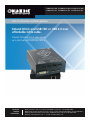
ACS4002A-R2 ACS4004A-R2 ACS4011A-R2 ACS4002A-R2-MM ACS4004A-R2-MM ACS4011A-R2-MM ACS4002A-R2-SM ACS4004A-R2-SM ACS4011A-R2-SM DVI-D CATx/Fiber KVM Extenders Extend DVI-D and USB HID or USB 2.0 over BLACK BOX affordable CATx cable. ® Transmit KVM and DVI-D video signals up to 460 feet over backbone cabling. Customer Support Information Order toll-free in the U.S.: Call 877-877-BBOX (outside U.S. call 724-746-5500) FREE technical support 24 hours a day, 7 days a week: Call 724-746-5500 or fax 724-746-0746 Mailing address: Black Box Corporation, 1000 Park Drive, Lawrence, PA 15055-1018 Web site: www.blackbox.com • E-mail: [email protected] FCC Statement Federal Communications Commission and Industry Canada Radio Frequency Interference Statements This equipment generates, uses, and can radiate radio-frequency energy, and if not installed and used properly, that is, in strict accordance with the manufacturer’s instructions, may cause interference to radio communication. It has been tested and found to comply with the limits for a Class A computing device in accordance with the specifications in Subpart B of Part 15 of FCC rules, which are designed to provide reasonable protection against such interference when the equipment is operated in a commercial environment. Operation of this equipment in a residential area is likely to cause interference, in which case the user at his own expense will be required to take whatever measures may be necessary to correct the interference. Changes or modifications not expressly approved by the party responsible for compliance could void the user’s authority to operate the equipment. This digital apparatus does not exceed the Class A limits for radio noise emission from digital apparatus set out in the Radio Interference Regulation of Industry Canada. Le présent appareil numérique n’émet pas de bruits radioélectriques dépassant les limites applicables aux appareils numériques de la classe A prescrites dans le Règlement sur le brouillage radioélectrique publié par Industrie Canada. We‘re here to help! If you have any questions about your application or our products, contact Black Box Tech Support at 724-746-5500 or go to blackbox.com and click on “Talk to Black Box.” You’ll be live with one of our technical experts in less than 30 seconds. Page 2 724-746-5500 | blackbox.com ACS4002A-R2 NOM Statement Instrucciones de Seguridad (Normas Oficiales Mexicanas Electrical Safety Statement) 1. Todas las instrucciones de seguridad y operación deberán ser leídas antes de que el aparato eléctrico sea operado. 2. Las instrucciones de seguridad y operación deberán ser guardadas para referencia futura. 3. Todas las advertencias en el aparato eléctrico y en sus instrucciones de operación deben ser respetadas. 4. Todas las instrucciones de operación y uso deben ser seguidas. 5. El aparato eléctrico no deberá ser usado cerca del agua—por ejemplo, cerca de la tina de baño, lavabo, sótano mojado o cerca de una alberca, etc. 6. El aparato eléctrico debe ser usado únicamente con carritos o pedestales que sean recomendados por el fabricante. 7. El aparato eléctrico debe ser montado a la pared o al techo sólo como sea recomendado por el fabricante. 8. Servicio—El usuario no debe intentar dar servicio al equipo eléctrico más allá a lo descrito en las instrucciones de operación. Todo otro servicio deberá ser referido a personal de servicio calificado. 9. El aparato eléctrico debe ser situado de tal manera que su posición no interfiera su uso. La colocación del aparato eléctrico sobre una cama, sofá, alfombra o superficie similar puede bloquea la ventilación, no se debe colocar en libreros o gabinetes que impidan el flujo de aire por los orificios de ventilación. 10. El equipo eléctrico deber ser situado fuera del alcance de fuentes de calor como radiadores, registros de calor, estufas u otros aparatos (incluyendo amplificadores) que producen calor. 11. El aparato eléctrico deberá ser connectado a una fuente de poder sólo del tipo descrito en el instructivo de operación, o como se indique en el aparato. 12. Precaución debe ser tomada de tal manera que la tierra fisica y la polarización del equipo no sea eliminada. 13. Los cables de la fuente de poder deben ser guiados de tal manera que no sean pisados ni pellizcados por objetos colocados sobre o contra ellos, poniendo particular atención a los contactos y receptáculos donde salen del aparato. 14. El equipo eléctrico debe ser limpiado únicamente de acuerdo a las recomendaciones del fabricante. 15. En caso de existir, una antena externa deberá ser localizada lejos de las lineas de energia. 16. El cable de corriente deberá ser desconectado del cuando el equipo no sea usado por un largo periodo de tiempo. 17. Cuidado debe ser tomado de tal manera que objectos liquidos no sean derramados sobre la cubierta u orificios de ventilación. 18. Servicio por personal calificado deberá ser provisto cuando: A: El cable de poder o el contacto ha sido dañado; u B: Objectos han caído o líquido ha sido derramado dentro del aparato; o C: El aparato ha sido expuesto a la lluvia; o D: El aparato parece no operar normalmente o muestra un cambio en su desempeño; o E: El aparato ha sido tirado o su cubierta ha sido dañada. ACS4002A-R2 724-746-5500 | blackbox.com Page 3 Trademarks Trademarks Used in this Manual Black Box and the Double Diamond logo are registered trademarks of BB Technologies, Inc. Any other trademarks mentioned in this manual are acknowledged to be the property of the trademark owners. Page 4 724-746-5500 | blackbox.com ACS4002A-R2 Table of Contents Table of Contents Specifications................................................................................................................................................................................................6 1.0 Quick Setup...................................................................................................................................................................................7 2.0 Overview........................................................................................................................................................................................8 2.1 Introduction.....................................................................................................................................................................9 2.2 Glossary...........................................................................................................................................................................9 2.3 Features......................................................................................................................................................................... 11 2.4 Product Range............................................................................................................................................................... 12 2.5 How to Use This Guide.................................................................................................................................................. 13 3.0 Installation................................................................................................................................................................................... 14 3.1 What‘s Included............................................................................................................................................................. 14 3.2 Interconnection Cable Requirements.............................................................................................................................. 15 3.3 System Setup................................................................................................................................................................. 16 3.4 Diagnostic LEDs............................................................................................................................................................. 21 4.0 Service Setup...............................................................................................................................................................................22 4.1 Setup at the Local Unit...................................................................................................................................................23 4.2 Setup at the Remote Unit...............................................................................................................................................25 4.3 Setup for the On Screen Display (OSD—ACS4011A-R2 only)..........................................................................................26 4.4 Setup for VGA Input (ACS4011A-R2 Family)...................................................................................................................36 5.0 Troubleshooting...........................................................................................................................................................................38 5.1 Monitor Errors...............................................................................................................................................................38 5.2 USB Keyboard and USB Mouse Errors.............................................................................................................................38 5.3 USB-HID Device Errors...................................................................................................................................................39 5.4 Other Errors...................................................................................................................................................................39 Appendix A: Sample Applications...............................................................................................................................................................40 Appendix B: Rackmount Options................................................................................................................................................................42 Appendix C: Technical Support...................................................................................................................................................................46 Appendix D: Supported Video Modes.........................................................................................................................................................48 Appendix E: Information in Internal DDC....................................................................................................................................................50 Appendix F: Connectors............................................................................................................................................................................. 51 ACS4002A-R2 724-746-5500 | blackbox.com Page 5 Specifications Specifications Distance — Maximum, CATx AWG 24: 400 ft. (120 m), CATx S/UTP cable, EIA/TIA 56A, TSB 36 or digital STP 17-03170, four pairs 24 AWG wiring, EIA/TIA 568A (1000BASET); Maximum, CATx patch cable 26/7 AWG 200 ft. (60 m), CATx S/UTP cable, EIA/TIA 56A, TSB 36 or Digital STP 17-03170, four pairs 26/7 AWG wiring EIA/TIA 568A (1000BASET). Attenuation Detect Accuracy — ±0.05 dB/dB CE Approval — Yes RoHS — Yes Connectors — Video source: DVI-D up to 1920 x 1200 @ 60 Hz; VGA: up to 1600 x 1200 @ 60 Hz; (ACS401A family only); Monitor: DVI-D up to 1920 x 1200 @ 60 Hz; Keyboard: USB; Mouse: USB 2-/3-button and wheel mouse; LC (Fiber): 1000 Mbps, Gigabit Ethernet; RJ-45: 1000 Mbps, EIA/TIA 568B Gigabit Ethernet. Operating Environment — Temperature: 41 to 113° F (5 to 45° C); Humidity: 0 to 80%, noncondensing Power — Voltage: 100-240 VAC, 0.5A, 47-63 Hz/5 VDC-2000 mA Local Units, Maximum: 1A @ 240V; 2A @ 100V; Remote Units, Maximum: 1A @ 240V; 2A @ 100V Size — Local and remote: 1.7"H x 4"W x 5.6"D x (4.3 x 10.3 x 14.3 cm) Shipping Size: 8.7"H x 4.3"W x 2.7"D (22 x 11 x 7 cm) Weight — Local and remote: 1.3 lb. (0.6 kg); Shipping: 3.5 lb. (1.6 kg) Page 6 724-746-5500 | blackbox.com ACS4002A-R2 Chapter 1: Setup 1.0 Quick Setup This section briefly describes how to install your KVM extender system. Unless you are an experienced user, we recommend that you follow the full procedures described in the rest of this manual. Check PSUs and connection to power outlet Check the CATx – Fiber cable, and its connectors Check settings of the graphic card or boot CPU Figure 1-1. Quick Setup. ACS4002A-R2 724-746-5500 | blackbox.com Page 7 Chapter 2: Overview 2.0 Overview With the DVI-D/-I CATx/Fiber KVM-Extender, you can remotely locate monitors, keyboards and mice up to 140 m (459.3 ft.) away from your CPU over CATx, or up to 10 km (6.2 mi) with single-mode fiber. Wherever long distances are required, e.g. airports, industrial plants, call-centers or in distributed computer centers, the DVI-D/-I CATx/Fiber KVM-Extenders are the ideal way to remotely locate your console. We offer two families with three different types: one family with devices for DVI-I (DVI-D/-I + VGA) and one family with USB 2.0 transparent support – CATx, multimode and single-mode. The product codes covered in this manual are: ACS4002A-R2: KVM Extender DVI-D, USB-HID + USB 2.0, CATx ACS4002A-R2-MM: KVM Extender DVI-D, USB-HID + USB 2.0, Multimode ACS4002A-R2-SM: KVM Extender DVI-D, USB-HID + USB 2.0, Single-mode ACS4004A-R2: KVM Extender DVI-D, DVI-D with 4 USB HID PORTS ACS4004A-R2-MM: KVM Extender DVI-D, DVI-D with 4 USB HID PORTS, Multimode ACS4004A-R2-SM: KVM Extender DVI-D, DVI-D with 4 USB HID PORTS, Single-mode ACS4011A-R2: KVM Extender DVI-I (VGA), USB HID, CATx ACS4011A-R2-MM: KVM Extender DVI-I (VGA), USB HID, Multimode ACS4011A-R2-SM: KVM Extender DVI-I (VGA), USB HID, Single-mode NOTE: Other models are available. For details, call Tech Support. Page 8 724-746-5500 | blackbox.com ACS4002A-R2 Chapter 2: Overview 2.1 Introduction A CATx/Fiber KVM Extender enables you to mount a CPU in a secure rack/cabinet or data center and access it from a remote location, up to 140 meters away. A basic KVM extension system is comprised of a local unit and a remote unit. The local unit connects directly to the computer (or a KVM switch system) using the supplied cable(s). The user console (keyboard, mouse, and monitor) attaches to the remote unit. The remote and local units communicate video and data information along the interconnecting cables. Local units offer dual access, allowing the connection of a second monitor close to the computer. A CATx/Fiber KVM Extender is used to extend the maximum distance between a CPU and a keyboard/monitor/mouse. In addition, a KVM extender is beneficial in installations in electromagnetic hazardous environments (EMI). Regular KVM extender cables (and extenders using traditional cables) have inherent distance limitations, and EMI interference may reduce the maximum distance and/or reliability. With a DVI-D/-I CATx Extender system, these limitations are no longer an issue. 2.2 Glossary The following terms are used in this guide: Table 2-1. Glossary Term Definition CATx Any Category 5, 5e, 6, or higher cable, solid 24 AWG. Although flexible 27/7 AWG cables can be used too, the lengths of flexible cables count twice in the calculation of the total distance. Fiber 9-μ Single-mode or 50-μ/62.5-μ Multimode fiber cable. KVM Keyboard, video, and mouse. Console ACS4002A-R2 Keyboard, mouse, and monitor Dual Access A system allowing connection of local and remote user consoles. Single-Head An extender system that supports one monitor and keyboard/mouse Dual-Head An extender system that supports two monitors and keyboard/mouse DVI Digital video standard, installed by Digital Display Working Group (www.ddwg.org) R, G, B, CLOCK in a data stream with up to 3x 1.6 Gbps. Signals are TMDS Level. PSU The desktop power supply connected to the local/remote unit. HID Human interface devices (HIDs) are units which are used for human access to the CPU. They are a USB-device class of their own (e.g. memory devices etc.). In addition to keyboards and mice, it includes touchscreens, light pens, fingerprint sensors, graphics tablets, etc. 724-746-5500 | blackbox.com Page 9 Chapter 2: Overview USB Connection CPU Transmitter/Local Unit CATx or Fiber Cable Receiver/Remote Unit USB Connection Figure 2-1: DVI-D/-I CATx – KVM Extender system (example) Page 10 724-746-5500 | blackbox.com ACS4002A-R2 Chapter 2: Overview 2.3 Features All extenders have the following features: • Support for DVI-D graphics cards • Support for USB keyboards and mice (USB-HID) NOTE: Devices with USB-HID support only keyboard and mice. It’s possible that other HIDs like touchscreens, graphics tablets, bar-code readers or similar are supported – but that isn’t guaranteed. If you have questions, call our FREE Tech Support. The DVI-D/-I CATx/Fiber KVM-Extender for USB-HID is not suitable for use with other USB devices like scanners, webcams, flash drives, etc. NOTE: The USB-HID device never supports more than two devices – keyboard and mouse or keyboard and touchscreen, etc., but not, for example, keyboard, mouse and touchscreen simultaneously. A hub is allowed but does not increase the number of supported devices. Maximum resolution: DVI-D: 1920 x 1200 @ 60 Hz over all allowed distances all resolutions below of 1600 x 1200 with refresh rates of at least 75 Hz. • Supporting 16-bit/24-bit auto switching or fixed 24-bit color depth (user selectable) • Status indicator LEDs on each device. • Small footprint chassis. • CPU cables and adapters included. • Rackmount kit available. ACS4002A-R2 family: • Additional USB 2.0 transparent high-speed transmission (requiring an additional CATx cable or fiber pair). Four devices can be attached directly at the Remote Unit—more by using regular USB hubs. ACS4004A-R2 family: • Support for DVI-D video and (4) USB HID devices. ACS4011A-R2 family • Support for DVI-I input—either DVI-D or VGA input. • Built-in scaler enables you to resize the input frame to fit to the attached monitor. NOTE: Other models are available but may not be shown in this user manual. ACS4002A-R2 724-746-5500 | blackbox.com Page 11 Chapter 2: Overview 2.4 Product Range There are nine products in the range and various upgrade kits: Table 2-2. Products Product ACS4002A-R2 ACS4002A-R2-MM ACS4002A-R2-SM ACS4004A-R2 KVM Extender DVI-D, USB-HID + USB 2.0, CATx KVM Extender DVI-D, USB-HID + USB 2.0, Multimode KVM Extender DVI-D, USB-HID + USB 2.0, Single-Mode KVM Extender DVI-D, USB-HID CATx ACS4004A-R2-MM KVM Extender DVI-D, USB-HID, Multimode ACS4004A-R2-SM KVM Extender DVI-D, USB-HID, Single-Mode ACS4011A-R2 Page 12 Definition KVM Extender DVI-I (VGA), USB-HID, CATx ACS4011A-R2-MM KVM Extender DVI-I (VGA), USB-HID, Multimode ACS4011A-R2-SM KVM Extender DVI-I (VGA), USB-HID, Single-Mode ACS1009A-RMK 19"/1U/24 IV rackmount kit to mount four 1.1"H devices ACS2209A-RMK 19"/1U rackmount- kit to mount four devices 1.7"H 724-746-5500 | blackbox.com ACS4002A-R2 Chapter 2: Overview 2.5 How to Use This Guide This guide describes the installation and configuration of the DVI-D/-I CATx/Fiber – Extender Series. Although the connection and operation of the system is relatively straightforward, you should consider the following before getting started: Connection and Compatibility If you have purchased an Extender Kit, this will contain all the cables required to connect the local unit to your PC or KVM switch. Please see also: 3.1 What‘s Included. For information about connection and installation, see 3.2 Interconnection Cable Requirements. DDC information Normally it is not necessary to make any adjustments to the DVI-D/-I CATx/Fiber- Extender. However, in some circumstances, it may be necessary to redefine the source of DDC information for the CPU. By default, the DVI-D/-I CATx/Fiber KVM-Extender uses its own internal DDC table. If this setting does not satisfy your requirements, the DDC table can either be switched to the locally attached screen or could be downloaded from a remotely located screen and stored in the internal DDC table. To modify the DDC setup, see 4.0 Service Setup. Selecting the moment of switching to the next frame The transmission of screen data is not synchronous to the screen change of the graphics card. Normally, the transmission is terminated during displaying a frame on the screen. If the device switches to the new frame during the displaying period of the old frame (somewhere on the screen), it’s possible, and that you can see horizontal screen breaks in the moment of switching (default). On the other hand, the device must idle, until the actual frame is displayed completely (until VSYNC) -> the number of frames per second transmitted sinks. To modify the switching behavior, see 4.0 Service Setup. Selection of color reduction for transfer acceleration You can select, whether always 24-bit colors (=full color depth) are transmitted or whether the compression algorithm automatically switches between 16- and 24-bit colors to accelerate the data transfer (default). Normally the difference between 24-bit and 16-bit is not recognizable but under some special circumstances, e.g. in photo processing installations, there might be disturbing color aberrations. However, the automatic color switching enhances the frame count transmitted per second; fixed 24-bit color depth gives smooth color grades under all circumstances. Choose the one that’s best for your application. To modify the color depth, see 4.0 Service Setup. ACS4002A-R2 724-746-5500 | blackbox.com Page 13 Chapter 3: Installation 3.0 Installation For first-time users, we recommend that you carry out a test placement, confined to a single room, before doing a full installation. This will enable you to identify and solve any cabling problems, and experiment with the KVM extender system more easily. 3.1 What‘s included All: • DVI-D/-I CATx/Fiber KVM-Extender pair (local and remote units) • (2) US power cords • (2) 5-VDC power supplies • 6-ft. (1.8-m) USB cable • 6-ft. (1.8-m) DVI-D video cable • User‘s manual with quick-install guide ACS4004A-R2 family (also includes): • 6-ft. (1.8-m) USB cable ACS4011A-R2 family (also includes): • 6-ft. (1.8-m) VGA-to-DVI-D video cable Page 14 724-746-5500 | blackbox.com ACS4002A-R2 Chapter 3: Installation 3.2 Interconnection Cable Requirements To connect the Local and Remote units you will need: • USB: Connect the supplied USB CPU cable to your CPU (KVM switch, etc.). Make sure that the connection is tension-free. • DVI: Connect the supplied DVI CPU cable to your CPU (KVM switch, etc.). Make sure that the connection is tension-free. • VGA/DVI: Connect the supplied VGA to DVI CPU cable to your CPU (KVM, switch, etc.). Make sure that the connection is tension-free. • CATx cable: Recommended cable: S/UTP (CATx) according EIA/TIA 56A, TSB 36 or Digital STP 17-03170. Four-pair 24 AWG connection according EIA/TIA 568A (10BASE-T). Use of cables from a higher category (CAT5e, CAT6, CAT7) is possible. NOTE: The use of unshielded CATx Cable is possible, but because of the higher electromagnetic noise/sensitivity the device class may not be reached. NOTE: The use of flexible cables (patch cable) 26 or 27 AWG is possible. Because of the higher loss of the stranded cables, the maximum distance is reduced to approximately half the value of solid cables. NOTE: A point-to-point connection is required. Having one or more patch panels in the line is possible and allowed. Not allowed is a connection from the CATx link interface (RJ-45) to any other products, especially telecommunications or network equipment. • Fiber cable: Two strands of fiber are required for single-head devices, four strands for dual-head devices. NOTE: The maximum distance will depend on device type and on fiber type used. Recommended cables: ACSxxxxA-MM: 50-µ multimode distance approximately 1312 ft. (400 m) ACSxxxxA-MM: 62.5-μ multimode distance approximately 656 ft. (200 m) ACSxxxxA-SM: Single-mode distance approximately 32,808 ft. (10 km) A point-to-point connection is required. You can have one or more patch panels in the line. You can’t have a connection from the fiber link interface (LC) to any other products, especially telecommunications or network equipment. Single-mode devices often work well on multimode fibers, but the reverse isn’t true. In addition, however, single-mode devices on multimode fibers may possibly double the distance on multimode fibers. There is no guarantee of this, and users are asked to perform tests within their own environments. • Power supply: Connect the supplied 5-VDC power supplies to the plug terminal on the rear of both local and remote units. ACS4002A-R2 724-746-5500 | blackbox.com Page 15 Chapter 3: Installation 3.3 System Setup To install your DVI-D/-I CATx/Fiber – Extender system: 1. Switch off all devices. 2. Connect your keyboard, monitor(s), and mouse to the remote unit 3. Using the supplied CPU cable(s), connect the USB and monitor connectors on the computer (or KVM switch). 4. Connect the interconnect cable to the INTERCONNECT socket(s). 5. Connect the 5-V power supply to power the unit. CAUTION: Only use the power supply originally supplied with this equipment or a manufacturer-approved replacement. 6. To attach a local (USB) keyboard/mouse, use additional USB port(s) at your CPU or use a USB hub between the CPU and local unit’s USB connector. 7. Power up the system. to CPU: DVI Connect to local DVI- monitor Connect to CPU: secondary USB Connect to CPU: USB Figure 3-1. ACS4002A-R2/ACS4002A-R2-xx local unit with 2x USB-HID + 4x USB-2.0. Page 16 724-746-5500 | blackbox.com ACS4002A-R2 Chapter 3: Installation 4x remote secondary USB 2.0 port. Remote DVI-monitor port— connect to remote console monitor. Remote keyboard/ mouse port. Figure 3-2. ACS4002A-R2/ACS4002A-R2-xx remote unit with 2x USB-HID + 4x USB-2.0. This port carries USB 2.0—connect to local/remote unit with CATx cable. Connect to 5V power supply. This port carries video and data signals—connect it to a local or remote unit with CATX cable. Figure 3-3. ACS4002A-R2-xx, local/remote unit: rear view CATx. ACS4002A-R2 724-746-5500 | blackbox.com Page 17 Chapter 3: Installation This connector carries USB 2.0. Connect it to a local or remote unit with fiber cable. Connect to 5V power supply. This port carries video and data signals. Connect it to a local or remote unit with fiber cable. Figure 3-4. ACS4002A-R2-xx local/remote unit: rear view fiber. ‘Eye‘ for IR-RC Connect to local DVImonitor. Connect to CPU: DVI-I port (DVI-D or VGA) Programming Connect to CPU: USB. Figure 3-5. ACS4002A-R2/ACS4011A-R2-xx, local unit with DVI-I input (DVI-D + VGA). Page 18 724-746-5500 | blackbox.com ACS4002A-R2 Chapter 3: Installation Remote DVI- monitor port. Connect to remote console monitor. Remote keyboard and mouse ports. Figure 3-6. ACS40011A-R2 /ACS40011A-R2-xx remote unit. Connect to 5-V power supply. This port carries video and data signals. Connect to the local/remote unit with CATx cable. Figure 3-7. ACS40011A-R2-xx local unit (CATx): rear view. Connect to 5V power supply. Connect to local/remote unit with fiber cable. Figure 3-8. ACS40011A-R2-xx local unit (fiber): rear view. ACS4002A-R2 724-746-5500 | blackbox.com Page 19 Chapter 3: Installation Connect to 5V power supply. This port carries video and data signals. Connect to the local/eremote unit wtih CATx cable. Figure 3-9. ACS40011A-R2-xx remote unit (CATx): rear view. Connect to 5V power supply. Connect to local/remote unit with fiber cable. Figure 3-10. ACS40011A-R2-xx remote unit (fiber): rear view. Page 20 724-746-5500 | blackbox.com ACS4002A-R2 Chapter 3: Installation 3.4 Diagnostic LEDs Each DVI-D/-I CATx KVM-Extender has indicator LEDs for Power, Video OK, Data Error, and Link Status. The Power LEDs are built into the Power switch. The location of the LEDs is shown below: Diagnostic LED: Data Error. Diagnostic LED: Power. Diagnostic LED: Link Status. Figure 3-11. Power, Data, and Link LEDs. Diagnostic LED: “Video is OK“. Figure 3-12. Diagnostic Video LED. Table 3-1. LED Information LED ACS4002A-R2 Appearance Diagnostics Power LED (Red LED) Off On Device not ready Device ready Video OK (Green LED) Off On No signal or invalid video signal detected Device ready Power LED (Green LED) Blinking On No CATx connection Device ready Power LED (Green LED) Off Blinking/on Device ready Errors through data transmission over CATx cable (Cable too long, too high attenuation or too much EMI interference) 724-746-5500 | blackbox.com Page 21 Chapter 4: Service Setup 4.0 Service Setup For standard applications, you should not need to make any adjustments to your DVI-D KVM Extender. However, in certain circumstances, you may need to open the Local Unit and/or the Remote Unit. To open one of the units, unscrew the Philips-type screws at both sides at the bottom of the device. Unscrew the UNC-type screws on each side of the monitor connectors. Carefully separate the lower and upper shells of the case. Fastening screws on the base. Fastening screws on the base. Figure 4-1. Location of fastening screws. 4.1 Setup at the Local Unit After unscrewing and opening the upper shell, place the device so the CATx connectors are on the right and the electrical connectors are on the left. The main circuit board then will look like this: Location of jumpers: indicated as JP1, JP3, JP3. Figure 4-2. Schematic of the interior of the local unit. Note the position of the jumpers. Page 22 724-746-5500 | blackbox.com ACS4002A-R2 Chapter 4: Service Setup DDC You can select whether the DDC is taken from the internal DDC table or from a local monitor. Or the DDC information could be downloaded from a remote monitor and stored into an internal table. Table 4-1. DDC Information LED Diagnostics From internal table From local monitor Loading the DDC Information from the Remote Monitor into the internal DDC Table (see also below: Loading the DDC Information from the Remote Monitor into the internal DDC Table) (default)) Loading the DDC Information from the Remote Monitor(s) into the internal DDC Table To load the DDC information from the remote monitor(s) into the internal DDC table: • Power up the CPU, the local unit, the remote (cables to the CPU connected) and the monitor. • Pull the monitor cable(s) from the remote unit; for dual-head devices, remove the cables from both monitors. • Make sure all monitors are turned on. • Plug the video cable of the remote monitor(s) into the remote unit and any local units. • The DDC information from the remote monitors will be read automatically, transferred to the local units and stored into the DDC EPROM. • After a successful programming of the DDC EPROM, the “Video-OK“ LED at the local unit will blink rapidly for approximately one second, indicating that you are finished. ACS4002A-R2 724-746-5500 | blackbox.com Page 23 Chapter 4: Service Setup Selection of Color Depth You may select between the Autoselect setting (the default setting), in which the system chooses whether 16- or 24-bit color (64 K or 16 M colors) is transmitted, or 24-bit color (16 M color). Autoselect mode optomizes the bandwidth between speed and color depth. When Autoselect is selected, 24 bit colors are transmitted as the screen content permits high data compression. When the video data does not allow reducing data, the colors are automatically reduced to 16 bit. This is auto selected in each line of the screen picture at any time. This mode makes the best compromise between speed and color depth. For the highest color depth at all times (with possibly reduced frame rates), select the 24-bit setting. Table 4-2. Color Depth Settings Color Depth JP3 16-bit/24-bit Autoselect setting. (Default). Otimizes the color depth based on screen content. 24-bit Page 24 724-746-5500 | blackbox.com ACS4002A-R2 Chapter 4: Service Setup 4.2 Setup at the Remote Unit After unscrewing and opening the upper shell, place the device so the CATx connectors are on the right and the electrical connectors are on the left. The main circuit board then will look like this: Location of jumpers: JP1, JP2, JP3 Figure 4-3. Schematic of the interior of the remote unit. Note the position of the jumpers. Selecting the moment to switch to the next frame The transmission of screen data is not synchronous to the screen change of the graphics card. Normally, the transmission is terminated while a frame on the screen is displayed. If the device switches to the new frame while the old frame is being displayed (somewhere on the screen), it is possible that you will see horizontal screen breaks during the switch. On the other hand, the device must idle until the frame is displayed completely (until VSYNC) -> at which point the number of frames per second transmitted may be reduced significantly. In this case, it is possible that you will see a stepping of the frames. Table 4-3. Color Depth Settings Moment to Switch ACS4002A-R2 JP3 Behavior Switching during HSYNC (default) Higher frame rate, but horizontal breaks may possibly be detectable. Switching during VSYNC Lower frame rate, but no horizontal breaks detectable; possibility of stepping pictures. 724-746-5500 | blackbox.com Page 25 Chapter 4: Service Setup 4.3 Setup for the ACS4011A-R2 On-screen Display (OSD) The following table summarizes the remote control sequence used in system configuration and video tuning on the ACS4011A-R2 family. Exit OSD Select next position/increase parameter Select previous position/decrease parameter Enter OSD Direct brightness control Direct contrast control Reset to factory defaults (press twice) Back to the menu selection Figure 4-4. Infrared Remote Control (IR-RC). Page 26 724-746-5500 | blackbox.com ACS4002A-R2 Chapter 4: Service Setup On-Screen Display (OSD) Utility If you are using a VGA format stored in the internal table, no adjustment should be required. In other cases, you may need to optimize the output using the integrated VGA to DVI Converter’s on-screen display (OSD). Version Information Screen resolution and refresh rate of the video source Main menu icons Submenu/command icons Menu title Figure 4-5. On-Screen display utility. You can adjust the following properties using the IR-Remote Control directly (no OSD required): • Brightness/contrast • Reset to factory defaults You can adjust the following properties using the OSD: • Auto Configuration ON/OFF • Color, color temperature adjustments • Brightness/contrast • Input image sizing • Output image scaling and sizing • OSD operation, factory reset ACS4002A-R2 724-746-5500 | blackbox.com Page 27 Chapter 4: Service Setup Using the OSD You can access the OSD by using the Infrared Remote Control (IR-RC) unit. More brightness More contrast Press twice to reset to factory defaults (from flash) Less brightness Less contrast Figure 4-6. Using the IR-RC. ESC Key: Exit the OSD without saving values. Left Arrow: Enter Key: Pop up the Right Arrow: Navigate to the left Navigate to the right OSD, selection functions [Parameter (-)]. and submenus, and store [Parameter (-)]. modified parameters. Figure 4-7. Navigating within the OSD using the IR-RC. Icons The OCD is an icon-based utility. These symbols, which appear across the top of the OCD display, show the main menu categories: Input Select: Specify whether the input is VGA or DVI. Scale Mode: Select the screen resolution of the attached display and select one of four scaling modes. Brightness/Contrast: Adjust brightness or contrast or reset to default values. Color: Adjust color calibration, temperature, flesh/skin tone, hue, and saturation. Image: Adjust the pixel clock and phase. Define picture size and position. Tools: Set the OSD position and size, and the factory reset. Figure 4-8. OSD menu icons. Page 28 724-746-5500 | blackbox.com ACS4002A-R2 Chapter 4: Service Setup Navigating the OSD Utility 1. Use the left and right arrow, shown in Figures 4-3 and 4-7 to highlight the icon you want. The OSD displays additional icons relating to commands in the selected menu category. 2. Press the Enter key. The OSD highlights the first command icon. 3. Use the Left and Right arrow keys to highlight the command or submenu you want. In the case of the latter, your selection will cause the OSD to display additional command icons (Color Temperature commands, for example). 4. Press the Enter key to accept a highlighted command. If this requires the increase or decrease of a value (Contrast, for example), the OSD displays a value bar: Figure 4-9. OCD Value Bar. 5. Use the left and right arrow keys to change the value. 6. In many cases, after you have chosen a new setting, the OSD displays the following confirmation message: Figure 4-10. Confirmation Dialog 7. Highlight the “Yes“ button and press the Enter key to confirm your choice. Or, highlight the “No“ button and press the Enter key to discard the new setting and restore the previous value. 8. Select the Exit icon to close a submenu. 9. Press the Esc key to close the OSD, saving all settings, and restore normal mouse and keyboard functions. The table below summarizes the keyboard actions and icons used to navigate the OSD utility, and to select and adjust the VGA to DVI Converter’s parameters: Table 4-4. DDC Information Key or Icon, IR-RC Action Close the OSD, and restore normal keyboard and mouse functions. Return to the previous menu selection. Open the highlighted menu or submenu; also, accept the command. Select the previous menu or command icon; decrease the highlighted parameter. Select the next menu or command icon; increase the selected parameter. ACS4002A-R2 724-746-5500 | blackbox.com Page 29 Chapter 4: Service Setup Menu Item: Input Selection From the main menu, select this “Input Select“ icon to choose the type of input source: Select VGA Source Select DVI Source Return to main menu (Actual source is noted with a check mark.) Figure 4-11. Input selection. Menu Item: Brightness/Contrast From the main menu, select the “Brightness/Contrast“ icon to adjust the brightness and contrast of the video image, or to adjust the black level of a display: Adjust Brightness Adjust Contrast Adjust Black level Return to main menu Figure 4-12. Brightness/Contrast adjustment. Page 30 724-746-5500 | blackbox.com ACS4002A-R2 Chapter 4: Service Setup Menu Item: Scale Mode From the main menu, select the Scale Mode icon to to specify the physical resolution of the attached screen. These settings enable you to best match the pictures on a TFT screen. Use “output scaling“ to stretch the picture to the maximum available screen space. No change to the resolution/refresh rate. The output resolution/refresh rate is the same as the input refresh rate Choose from among three fixed screen resolutions: 800x600; 1024x786; and 1280x1024 Return to main menu Figure 4-13. Scale Mode adjustment. NOTE: There is no altering in refresh rates possible. If sourcing 50 Hz or 75 Hz, make certain your monitor is able to process these refresh rates. Otherwise, select 60-Hz refresh rate from your graphics card. Note that rescaling any 16:9 resolution to a 4:3 resolution will cause a misalignment in aspect ratio. NOTE: If using DVI-D input and the scaling function for downsizing the picture resolution, note, that there are limits for resizing: The input pixel clock must remain below 1.9x output pixel clock. This means: For output of 800 x 600, the maximum input resolution is 1024 x 768. For output of 1024 x 768, the maximum input resolution is 1680 x 1050 (Reduced Blanking). For output of 1280 x 1024, all maximum input resolutions are possible. With VGA input signals, there are no limits for up- or downscaling. ACS4002A-R2 724-746-5500 | blackbox.com Page 31 Chapter 4: Service Setup Menu Item: Color From the main menu, select the “Color“ icon to adjust the color balance of the video image. The menu provides a number of options including automatic calibration, manual adjustment in RGB or CMY color space, along with hue and saturation adjustment and the setup of flesh tones. Automatic color calibration Standard RGB color selection View Color temperature submenu, below. Adjust flesh tones Set up colors in CMY space; automatically adjusts settings in RGB space. Hue Saturation Back to main menu Figure 4-14. Color adjustment. Menu Item: Color Temperature submenu From the main menu, select the Color Temperature submenu to set up the color profile in the RGB color space, or by using one of five pre-defined color temperatures. To view this submenu, select the Colors icon from the main menu, and then select the Color Temperature icon as shown here. Set up colors in RGB space. Automatically adjusts settings in CMY space. Choice of five color temperature settings: 4200 k, 5000 k, 6500 k, 7500 k, and 9300 k. Back to Color menu Figure 4-15. Color Temperature submenu. Page 32 724-746-5500 | blackbox.com ACS4002A-R2 Chapter 4: Service Setup Menu Item: Image From the main menu, select the “Image“ menu to adjust the vertical and horizontal screen position and to set the pixel clock and phase. Automatic detection of the number of pixels per line and the best phase (best point for A/D conversion within each pixel). Manually adjust the number of pixels per line (pixel clock). Manually adjust the best phase (best point for A/D conversion within each pixel). Back to main menu. Manually adjust the vertical picture position. Manually adjust the horizontal picture position. Figure 4-16. Image menu. Menu Item: Tools From the main menu, select the “Tools“ menu to set the position and size of the OSD window, to adjust the sharpness for a fixed resolutioini setting, to reset the VGA to DVI Converter system to its factory defaault setting or to provide a test pattern. Set the position of the OSD window. Calling Factory Reset submenu. Choose whether to automatically adjust pixels per line and pixels phase after a mode change. (See Navigating the OCD Utility in 4.3 Setup). Back to main menu. Adjust sharpness (only when doing scaling to fixed resolutions). When resolution is changed by an imposed fixed resolution, sharpness can be affected. Use this option to switch between three settings for optimum sharpness.. Display a ‘burst‘ pattern for monitor setup. (See 4.4 Setup Instructions for VGA Input). Selecting color depth (HiColor/LoColor). Figure 4-17. Tools menu. ACS4002A-R2 724-746-5500 | blackbox.com Page 33 Chapter 4: Service Setup Menu Item: OSD submenu From the Tools menu, select the “OSD“ submenu, to define the position and size of the OSD window. Manually adjust the horizontal position of the OSD window. Manually adjust the vertical position of the OSD window. Back to Tools menu. Toggle the size of the OSD window between single and double size. Figure 4-18. The OSD submenu, from the Tools menu. Menu Item: Auto Configuration submenu From the Tools menu, select the Auto Configuration icon. Use the Auto Configuration submenu to define whether the Converter carries out automatic detection of the number of pixels per line and the best phase after a mode change (a change of screen resolution and/or refresh rate at the graphics source). Using automatic detection (while displaying an appropriate test pattern) ensures an optimized image but the procedure introduces a delay in the picture appearing on the attached console screen. If you want the picture to appear as fast as possible, you may want to disable this feature. Auto Configuration is disabled in the default factory settings. Disable automatic detection of pixels per line and phase after a mode change. Enable automatic detection of pixels per line and phase after a mode change. Back to Tools menu. Figure 4-19. The Auto Configuration submenu, from the Tools menu. Page 34 724-746-5500 | blackbox.com ACS4002A-R2 Chapter 4: Service Setup Menu Item: DDC Configuration Menu From the main menu, select the DDC Configuration menu, to define which DDC information is transmitted to the graphics card. As long as there is no transparent DDC communication, there is a “virtual DDC“ built into the local unit (See Appendix E: Information in Internal DDC). You can either provide the DDC information of the secondary monitor attached to the local unit or the information from the internal DDC table. Use the information from the internal DDC table. Connect DDC lines directly from a locally attached monitor. Back to main menu. Create a VGA-DDC from the DVI DDC in the internal table. Figure 4-20. The DDC Configuration menu. NOTE: It is possible to load the DDC information of the remotely attached monitor into the internal DDC table. Refer to DDC Information in 2.5 How to Use This Guide. Under some circumstances, the local unit should identify itself as a “VGA monitor“ providing DDC information like a VGA screen (DVI-DDC and VGA-DDC are different). In this case, you can convert the internal DDC table to a VGA-DDC by hitting the “Create VGA“ button. ACS4002A-R2 724-746-5500 | blackbox.com Page 35 Chapter 4: Service Setup 4.4 Setup Instructions for VGA Input (ACS4011A-R2 Family) When converting from analog to digital signal, this extender will give you options to adjust and compensate in order to achieve the best possible video output. This procedure is designed to correct discrepancies in the video signal from analog/digital video conversion by the VGA to DVI Converter. 1. Display from your graphics source a picture with as much detail as possible. If possible, display a “burst-pattern“ (see Figure 4-21)—a picture with alternating, 1-pixel wide, black-and-white, vertical stripes. If you are unable to view the test card, display some black text on a white background. For example, you could open Notepad, maximize it to full screen, and fill the page with letter ‘I’s in a 12-pt. sans serif font. Proceed with Step 2. 2. Display the OSD. 3. Select the Image menu option: 4. Select the first command icon: Automatic detection of number of pixels per line and the best phase. 5. Assess the desktop test pattern. If the vertical stripes are sharp and without jitter or smearing, the adjustment has been successful. Go to Step 9. 6. If the picture quality is not acceptable after the automatic adjustment, you will have to manually adjust the pixel clock and pixel phase (in this order). 7. With a poorly adjusted pixel clock you may see one or more vertical areas, where the lines are smeared: Figure 4-21. If, after allowing the OSD to automatically adjust the pixel phase, the picture quality is not successful, you may see this type of distortion. In this case, you will need to manually adjust both the pixel clock and pixel phase. a. Return to the OSD utility and select this menu command: Manually adjust the number of pixels per line (pixel clock) from the Image menu. b. Adjust the pixel clock value until all stripes have disappeared. c. Confirm the setting. Page 36 724-746-5500 | blackbox.com ACS4002A-R2 Chapter 4: Service Setup 8. Problems with the pixel phase will cause horizontal noise, horizontal wave-formed lines, flicker, or smearing with a zebrapattern: Figure 4-22. When manually adjusting the pixel phase, you may see the type of noise that's shown here. You can use the OCD command Manually adjust the best phase to remove this distortion. a. From the OSD’s Image menu, select the menu command: Manually adjust the best phase (best point for A/D conversion within each pixel). b. Modify the phase until all distortions have disappeared. c. Confirm the setting. 9. If necessary, adjust the size of the visible part of the picture. (The horizontal and vertical size is displayed in numeric values for exact adjustment.) 10. If necessary, adjust the position of the visible part of the screen. It may be necessary to adjust the picture size (Step 9) again. 11. If appropriate, re-attach your TFT monitor and adjust its image according to the manufacturer’s instructions. ACS4002A-R2 724-746-5500 | blackbox.com Page 37 Chapter 5: Troubleshooting 5.0 Troubleshooting 5.1 Monitor Errors There isn‘t a picture Check the power supply connection at the local and remote units. Is the Power (red LED) at the local unit illuminated? (See 3.4 Diagnostic LEDs.) If not, the internal power supply may be damaged or there may be an internal error. Check that the interconnection cable is connected at the local unit and the remote unit. Is the Link Status LED illuminated? (See 3.4 Diagnostic LEDs.) If not, there may be a problem with the interconnection cable. Are there errors through data transmission over CATx cable—cable too long, too high attenuation or too much EMI interference? Is the Data Error LED illuminated or blinking? (See 3.4 Diagnostic LEDs.) If yes, check cable length and environment. Video OK LED is dark: CPU does not provide a video signal. Check the settings of the graphics card. Connect a monitor to the local output to see whether there is a signal or not. “Stepping“ pictures on displaying videos On high resolutions, the amount of data transmitted each second expires the capability of the data link. Therefore the data has to be reduced before transmitting. This is done in a first step by an RLE (=Run Length Encoding) algorithm. If this (loss less) compression does not reach the required amount, frames are dropped: the frame actually transmitted is transmitted completely even if the graphics card generates a new frame. This new frame is discarded. Because of this behavior, the count of frames per second (fps) may be reduced to a value, where “stepping“ pictures are seen. How to solve the problem: Use a lower resolution, which is slightly higher than the resolution of the recorded movie. Most movies only have a resolution of approximately 720 x 480 (NTSC) or 704 x 576 (PAL) or even 320 x 256 (VHS). If the monitor provides a higher resolution, it may scale these pictures. The picture quality is the same if the monitor or the CPU does the scaling. How to solve the problem: Set the color depth to 16-/24-bit AUTOSELECT. On moving pictures, the human eye is not able to see differences between so many colors. A reduction to 16-bit reduces the amount of data without (visible) effects. 5.2 USB Keyboard and USB Mouse Errors Your USB keyboard or mouse does not work Although we designed the devices to be as transparent as possible, we can’t ensure that all devices will be compatible. Your mouse is “stepping“ on your screen On high resolutions, the amount of data transmitted each second exceeds the capability of the data link. Therefore the data rate must be reduced before transmitting. This is done by using an RLE (Run Length Encoding) algorithm. If this (lossless) compression is not sufficient, frames are dropped, and as a result, you will see “stepping“ mouse movements. How to solve the problem: Use a lower resolution or use a desktop background that is better suitable for compression: avoid photos for background or horizontally graduated colors. Or better yet, use monochrome backgrounds, which allow for higher compression -> higher frame rates. Page 38 724-746-5500 | blackbox.com ACS4002A-R2 Chapter 5: Troubleshooting Your mouse is moving like it’s “hanging on a rubber band“ This problem is usually a combination of things, which adds up to a delay between the true mouse movement and the movement of the mouse pointer on the screen. Delays of up to 100–150 msec can be annoying. The total delay comes from (time values are approximate values): • 5 to 15 msec for mouse movement and data transmission to the CPU • 50 to 70 msec data processing time in the CPU until the refreshed data reach the graphics card output connector • 15 to 45 msec for transferring the graphics data into the local unit of the extender system and for transmitting to the remote unit (60 to 20 fps) • 10 to 100 msec data processing time in the display until the data is displayed on the screen (where 15 msec is normally only reached by CRT tubes) Total delay times between 85 to 230 msec are possible. Most of this delay is NOT caused by the extender system. The extenderbased delay is 5 to 15 msec of data transfer to the CPU and 15 to 45 msec of frame transfer to the remote unit—a total of 20 to 60 msec. Even a step from a 100 msec delay to a 140 msec (i.e. by inserting an extender system to a CPU-monitor link) may cause visible effects. Please note that even a monitor directly connected to a CPU has a delay of 70 to 175 msec. So (under special conditions) even the bare CPU/monitor link can have this problem. If you then add an extender system, the problem may worsen and is falsely attributed to the extender system, even though the extender is only a small part of the total problem. How to solve the problem: Use a display with a low delay time (NOTE: This is NOT the reaction time indicated by the manufacturer. This reaction time is only the time the display needs to switch a black pixel to get white or vice versa, but not how long it takes from receiving the data on the connector until they are displayed on the screen.) Use a lower resolution or use a desktop background that is better suited for compression: Avoid photos for background or horizontally graduated colors. It’s better to use monochrome backgrounds. They allow higher compression -> higher frame rates. If the link has frame dropping, a reduction from 30 fps to 60 fps saves 17 msec and from 20 fps to 60 fps saves 34 msec. 5.3 USB-HID Device Errors Your USB-HID device does not work Although our interface supports HID devices, we can't ensure that every connected device is supported. If you have problems, contact our FREE Tech Support. 5.4 Other Errors Your USB- device does not work You have connected a non-HID device to the HID port. For these ports, only HID devices are supported. (For example, on the ACS4002A-R2 model, there are six total USB ports at the remote unit. The two ports in the lower row are USB-HID only. Reconnect your USB device to one of the ports in the upper row.) ACS4002A-R2 724-746-5500 | blackbox.com Page 39 Appendix A: Sample Applications Appendix A: Sample Applications USB Connection CPU Transmitter/Local Unit CATx or Fiber Cable Receiver/Remote Unit USB Connection USB Devices Figure A-1. DVI-D CATx KVM Extender with USB 2.0 support. Page 40 724-746-5500 | blackbox.com ACS4002A-R2 Appendix A: Sample Applications USB Connection Transmitter/Local Unit CATx or Fiber Cable Receiver/Remote Unit USB Connection Figure A-2. DVI-D CATx KVM Extender supporting VGA and DVI-D. ACS4002A-R2 724-746-5500 | blackbox.com Page 41 Appendix B: Rackmount Options Appendix B: Rackmount Options The DVI-D CATx KVM Extender units can be mounted in a standard 19“ rack using the mounting kit either of two different rackmount kits: the ACS1009A-RMK for single-head devices, and ACS2209A-RMK for dual-head devices. Mounting the ACS1009A-RMK Rackmount-Kit Using the ACS1009A-RMK rackmount kit, you can mount up to four 4"H x 5.6"W x 1.1"D (10.3 x 14.3 x 2.9 cm) single-head devices into a 19" server rack. The rackmount kit requires 1U of rack space. Blank plates enable you to cover unused device positions. M2, 5x2 Spacers Base Plate M2, 5x5 Philips countersunk screws 3 Blank Plates Figure B-1. Rackmount Kit. Mounting Instructions: • Align the holes on the base plate with the vacant screw holes on the base of the device. • Fasten the base of the unit to the plate of the mounting kit. • Close the remaining gaps with blanking plates. NOTE: Use only the supplied short screws to prevent damages on the PCBs Page 42 724-746-5500 | blackbox.com ACS4002A-R2 Appendix B: Rackmount Options The Rackmount Kit (ACS1009A-RMK) enables mounting of up to four devices: Figure B-2. Mounting for one or two devices. Figure B-3. Mounting for three or four devices. NOTE: In the leftmost position, you can install a rackmountable PSU, ACS2209A-PS instead of an extender device. This PSU will enable you to power up to three single- or dual-head devices. Figure B-4. Mounting the optional ACS2209A-PS. ACS4002A-R2 724-746-5500 | blackbox.com Page 43 Appendix B: Rackmount Options Mounting the ACS2209A-RMK Rackmount Kit Using the ACS2209A-RMK rackmount kit, you can mount up to four 4"H x 5.6"W x 1.7"D (10.3 x 14.3 x 4.2 cm) dual-head devices into a 19" server rack. The rackmount kit requires 1U of rack space. Blank plates enable you to cover unused device positions. M2, 5x2 Spacers Base Plate M2, 5x5 Philips countersunk screws 3 Blank Plates Figure B-5. Mounting with the ACS2209A-RMK Rackmount Kit. Mounting Instructions: • Align the holes on the base plate with the vacant screw holes on the base of the device. • Fasten the base of the unit to the plate of the mounting kit. • Close the remaining gaps with blank plates. NOTE: Use only the supplied short screws to prevent damages on the circuit boards. Page 44 724-746-5500 | blackbox.com ACS4002A-R2 Appendix B: Rackmount Options The ACS2209A-RMK rackmount kit enables mounting of up to four devices in the following manner: Figure B-6. Mounting for one or two devices. Figure B-7. Mounting for three or four devices. NOTE: In the leftmost position, you can install a rackmountable power supply unit (PSU) (ACS2209A-PS) instead of an extender device. This PSU will enable you to power up to three single- or dual-head devices. Figure B-8. Mounting the optional ACS2209A-PS. ACS4002A-R2 724-746-5500 | blackbox.com Page 45 Appendix C: Technical Support Appendix C: Technical Support If you determine that your DVI-D/-I KVM Extender is malfunctioning, do not attempt to alter or repair it. It contains no userserviceable parts. Contact Technical Support at Black Box. Before you call, make a record of the history of the problem. We will be able to provide more efficient and accurate assistance if you have a complete description, including: • The firmware-revision level printed on the bottom of the extender (very important, especially for keyboard and mouse problems); The DVI-D/-I- KVM extender’s firmware revision level: Version Number Format: Board: xxLO/RE Myyy Pzzz Auuu Gvvvvvv Transceiver: C/M/S xx Pyy Mzz Keyboard/Mouse: P/U xx Vyyy • The nature and duration of the problem. • When the problem occurs. • The components involved in the problem—what type of computers, what type of keyboard, brand of mouse, make and model of monitor, type and make of cable, etc. • Any particular application that, when used, appears to create the problem or make it worse. • The results of any testing you’ve already done. To solve some problems, it might be necessary to upgrade the extender’s firmware. Our Tech Support technicians will arrange for you to receive the new firmware and will tell you how to install it. Shipping and Packaging If you need to transport or ship your DVI-D/-I- KVM Extender: • Package it carefully. We recommend that you use the original container. • If you are shipping it for repair, please include the exender’s external power supplies. If you are returning it, please include everything you received with it. Before you ship the extender back to Black Box for repair or return, contact Tech Support to get a return authorization (RA) number. Page 46 724-746-5500 | blackbox.com ACS4002A-R2 Appendix C: Technical Support Black Box Technical Support Table C-1. Black Box Technical Support Contact Information. Country Web Site and Email Phone US www.blackbox.com [email protected] 724-746-5500 724-746-0746 Austria www.black-box.at [email protected] +43 1 256 98 56 +43 1 256 98 56 Belgium www.blackbox.be [email protected] [email protected] [email protected] +32 2 725 85 50 +32 2 725 92 12 Denmark www.blackbox.dk [email protected] +45 56 63 30 10 +45 56 65 08 05 Finland www.blackbox.fi [email protected] +358 201 888 800 +358 201 888 808 France www.blackbox.fr [email protected] +33 820 07 09 11 +33 820 05 07 09 www.black-box.de [email protected] +49 811 5541 110 +49 811 5541 499 www.blackbox.co.uk [email protected] +353 1 662 2466 +353 1 662 2477 Germany Ireland Italy Netherlands Norway Spain Sweden Switzerland UK ACS4002A-R2 Fax www.blackbox.it [email protected] +39 02 27 404 700 +39 02 27 400 219 www.blackbox.nl [email protected] +31 30 241 7799 +31 30 241 4746 www.blackboxnorge.no [email protected] +47 55 300 710 +47 55 300 701 www.blackbox.es [email protected] +34 916590732 +34 916239784 www.blackboxab.se [email protected] +46 8 44 55 890 +46 08 38 04 30 www.black-box.ch [email protected] +41 55 451 70 71 +41 55 451 70 75 www.blackbox.co.uk [email protected] +44 118 965 6000 +44 118 965 6001 724-746-5500 | blackbox.com Page 47 Appendix D: Supported Video Modes Appendix D: Supported Video Modes Table D-1. Supported Video Modes. Description Hres pixels Vres lines V-freq HZ Hfreq kHz DotClk Mhz DOS Graphic Mode 640 350 69.6 31.3 25.0 VESA Standard 640 350 85.1 37.9 31.5 VGA 640 400 56.3 24.7 21.0 VGA 640 400 69.6 31.3 25.0 VESA Standard 640 400 85.1 37.9 31.5 VESA Standard 640 480 60.2 31.5 25.3 Mac Mode 640 480 67.0 35.0 31.5 VESA Standard 640 480 72.8 37.9 31.5 VESA Standard 640 480 75.0 37.5 31.5 VESA Standard 640 480 85.0 43.3 36.0 DOS Text Mode 720 400 69.6 31.5 28.1 VESA Standard 720 400 85.0 37.9 35.5 NTSC progressive 720 480 59.9 31.5 27.0 PAL progressive 720 576 50.0 31.3 37.0 VESA Standard 800 600 56.3 35.2 36.0 VESA Standard 800 600 60.3 37.9 40.0 VESA Standard 800 600 72.2 48.1 50.0 VESA Standard 800 600 75.0 46.9 49.5 VESA Standard 800 600 85.1 53.7 56.3 Mac Mode 832 624 75.1 49.7 55.5 VESA Standard 1024 768 60.0 48.4 65.0 VESA Standard 1024 768 70.1 56.5 75.0 SUN Mode 1024 768 72.2 57.8 75.2 VESA Standard 1024 768 72.0 60.0 78.8 VESA Standard 1024 768 85.0 68.7 94.5 DMT1185 1152 864 70.0 63.8 100.0 Mode 1152 864 70.0 63.8 94.5 VESA Standard 1152 864 75.0 67.5 108.0 SUN Mode 1152 900 66.0 61.8 94.5 VESA CVT 16:9 1280 720 60.0 44.8 74.5 WXGA 1280 768 60.0 48.1 81.2 WXGA 1280 768 60.2 47.8 80.0 WXGA 16:10 CVT 1280 800 59.8 49.7 83.5 VESA Standard 1280 960 60.0 60.0 108.0 DMT127A 1280 960 75.0 75.0 126.0 VESA Standard 1280 960 85.0 85.9 148.5 Page 48 724-746-5500 | blackbox.com ACS4002A-R2 Appendix D: Supported Video Modes Table D-1. Supported Video Modes, continued. Description Hres pixels Vres lines V-freq HZ Hfreq kHz DotClk Mhz TV 1280 1024 50.0 53.4 90.0 VESA Standard 1280 1024 60.0 64.0 108.0 SUN Mode 1280 1024 66.0 71.7 115.8 SGI 1280 1024 72.0 76.7 128.8 HG Workstation B123L 1280 1024 72.0 78.1 135.0 VESA Standard 1280 1024 75.0 80.0 1325.0 VESA Standard 1280 1024 85.0 91.1 157.5 TV Mode 16:9 1360 765 60.1 47.6 84.5 Plasma TV 16:9 1360 768 60.0 47.7 85.5 NVIDIA 4:3 1400 1050 59.8 65.2 121.5 TV Mode 16:10 1440 900 60.0 55.6 89.0 TV Mode 16:9 1600 900 59.9 55.8 118.8 SGI 1600 1024 72.0 77.6 158.3 USGA genlocked 1600 1200 50.0 75.0 138.0 VESA Standard 1600 1200 60.0 75.0 162.0 USGA reduced blank 1600 1200 60.1 75.4 140.6 WSXGA+16:10 DVI 1680 1050 59.9 64.7 119.0 WSXGA+ 16:10 VGA 1680 1050 60.0 65.3 146.3 TV Mode 16:9 1920 1080 50.0 56.4 148.5 TV Mode 16:9 1920 1080 59.9 66.6 138.5 EIA861B16:9 1920 1080 60.0 67.5 148.5 WUXGA 1920 1200 60.0 74.0 154.0 ACS4002A-R2 724-746-5500 | blackbox.com Page 49 Appendix E: Information in Internal DDC Appendix E: Information in Internal DDC Table E-1. Standard Timings. Resolution Refresh Rate Standard 720 x 400 70 Hz IBM VGA 720 x 400 88 Hz IBM XGA2 640 x 480 60 Hz IBM VGA 640 x 480 67 Hz Apple Mac II 640 x 480 72 Hz VESA 640 x 480 75 Hz VESA 800 x 600 56 Hz VESA 800 x 600 60 Hz VESA 800 x 600 72 Hz VESA 800 x 600 75 Hz VESA 832 x 624 75 Hz Apple Mac II 1024 x 768 60 Hz VESA 1024 x 768 70 Hz VESA 1024 x 768 75 Hz VESA 1280 x 1024 75 Hz VESA 1152 x 870 75 Hz Apple Mac II 1280 x 1024 60 Hz VESA STD 1280 x 1024 60 Hz VESA STD 1280 x 1024 60 Hz VESA STD 1360 x 765 60 Hz VESA STD 1400 x 1050 60 Hz VESA STD 1600 x 900 60 Hz VESA STD Native/Preferred Timing: 1024 x 768 @ 60 Hz, VESA Table E-2. Detailed Timings. Resolution Page 50 Refresh Rate Bandwidth 1280 x 800 60 Hz 83.5 MHz 1360 x 768 60 Hz 85.5 MHz 1680 x 1050 60 Hz 119 MHz 1600 x 1200 60 Hz 162 MHz 1920 x 1200 50 Hz 148.5 MHz 1920 x 1200 60 Hz 148.5 MHz 1920 x 1200 60 Hz 154 MHz 724-746-5500 | blackbox.com ACS4002A-R2 Appendix F: Connectors Appendix F: Connectors DVI-D/-I CATx/Fiber KVM-Extender Connector Pinouts 1 8 C1 C2 C5 17 24 C3 C4 Figure F-1. DVI-I female connector (Output connector for all devices and Input connector for the ACS4002A-R2 device - local unit). Table F-1. DVI-I Female Connector. Pin ACS4002A-R2 Signal Pin Signal Pin Signal 1 TMDS data 2- 9 TMDS data 1- 17 TMDS data 0- 2 TMDS data 2+ 10 TMDS data 1+ 18 TMDS data 0+ 3 TMDS data 2 ground 11 TMDS data 1 ground 19 TMDS data 0 ground 4 n.c. 12 n.c. 20 n.c 5 n.c. 13 n.c. 21 n.c 6 DDC Input (SCL) 14 +5V high impedance 22 TDMS clock ground 7 DDC Output (SDA) 15 Ground 23 TDMS clock + 8 Internal use 16 Hot plug recognition 24 TDMS clock - C1 Internal use C3 Internal use C2 n.c. C4 Internal use C5 Ground 724-746-5500 | blackbox.com Page 51 Appendix F: Connectors DVI-I Female Input Connector for the ACS4011A-R2 Local Unit 1 8 C1 C2 C5 17 24 C3 C4 Figure F-2. DVI-I female connector (Input connector for the ACS4002A-R2 local unit). Table F-2. DVI-I Female Connector. Pin Page 52 Signal Pin Signal Pin Signal 1 TMDS data 2- 9 TMDS data 1- 17 TMDS data 0- 2 TMDS data 2+ 10 TMDS data 1+ 18 TMDS data 0+ 3 TMDS data 2 ground 11 TMDS data 1 ground 19 TMDS data 0 ground 4 n.c. 12 n.c. 20 n.c 5 n.c. 13 n.c. 21 n.c 6 DDC Input (SCL) 14 +5V high impedance 22 TDMS clock ground 7 DDC Output (SDA) 15 Ground 23 TDMS clock + 8 Analog VSYNC 16 Hot plug recognition 24 TDMS clock - C5 Analog Ground C1 Analog Red C2 Analog Green C3 Analog Blue C4 Analog HSYNC 724-746-5500 | blackbox.com ACS4002A-R2 Appendix F: Connectors USB Connector, USB Type B (Connector at the Local Unit) 1 2 3 4 Figure F-3. USB Connector at the Local Unit, USB Type B. Table F-3. USB Connector at the Local Unit. Pin Signal 1 VCC (+5V) Red 2 Data - White 3 Data + Green 4 Ground Black USB Connector, USB Type A (Connector at the Remote Unit) 1 2 3 4 Figure F-4. USB Connector at the Remote Unit, USB Type A. Table F-4. USB Connector at the Remote Unit. ACS4002A-R2 Pin Signal 1 VCC (+5V) Red 2 Data - White 3 Data + Green 4 Ground Black 724-746-5500 | blackbox.com Page 53 Appendix F: Connectors CATx- Interface: Pinout according to EIA/TIA 568A (1000BASE-T) 1 8 Figure F-5. 1000BASE-T Pinout. Table F-5. USB Connector at the Remote Unit. Pin Pin 1 D1+ 5 D3- 2 D1- 6 D3+ 3 D2+ 7 D4+ 4 D2- 8 D4- Programming Port Figure F-6. Programming Port. Table F-6. Programming Port Pinout. Page 54 Pin Signal 1 TxD (to PC RxD) 2 RxD (from PC TxD) 3 DTR from PC 4 Ground- 724-746-5500 | blackbox.com ACS4002A-R2 Notes ACS4002A-R2 724-746-5500 | blackbox.com Page 55 Black Box Tech Support: FREE! Live. 24/7. Tech support the way it should be. Great tech support is just 30 seconds away at 724-746-5500 or blackbox.com. About Black Box Black Box Network Services is your source for an extensive range of networking and infrastructure products. You’ll find everything from cabinets and racks and power and surge protection products to media converters and Ethernet switches all supported by free, live 24/7 Tech support available in 30 seconds or less. © Copyright 2011. All rights reserved ACS4002A-2, version 1 724-746-5500 | blackbox.com