1
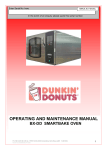
Convection Ovens Model BXC Smartbake 4-Tray & 10-Tray Belshaw Bros., Inc. 1750 22nd Ave. S. Seattle, WA 98144 Phone: 206-322-5474 Fax: 206-322-5425 Toll Free: 1-800-578-2547 E-mail: [email protected] http://www.belshaw.com If you accept the machine from the shipping company, you are, in effect, saying that the machine is in good condition, and you must pay for the machine. Belshaw cannot pay for shipping damage, because the freight company has accepted the machine from Belshaw in good condition, and is responsible for its safe delivery. For your protection, inspect the machine to see that no parts are bent, scratched, or otherwise damaged. If any damage has occurred in shipping, file a freight claim with the shipping company immediately. WARNING Keep this manual available at all times for use. EQUIPMENT RECORD Please provide the information below when you correspond with us about your machine. Purchased by _____________________________________________________________________ Installed by ______________________________________________________________________ Date of Installation ________________________________________________________________ Model number ___________________________________________________________________ Serial number 0303 MN-1881EN Belshaw Bros., Inc. 1750 22nd Ave. S. Seattle, WA 98144 Phone: 206-322-5474 Fax: 206-322-5425 Toll Free: 1-800-578-2547 E-mail: [email protected] http://www.belshaw.com Contents Sections 1 Installation 1 Unpacking the oven Dimensions and Specifications Installation Initial Cleaning Programming the control panel 1 1 2 2 3 2 5 Operation Operating conditions Operating using programmed settings 5 5 3 7 Cleaning and Maintenance Daily cleaning Weekly cleaning Maintenance Lubrication 4 7 7 8 8 Troubleshooting 10 Troubleshooting Oven 5 9 Diagrams 33 Limited Warranty Insert Belshaw Bros., Inc. 1750 22nd Ave. S. Seattle, WA 98144 Phone 206-322-5474 Fax 206-3225425 BXC Smartbake Oven MN-1881EN iii Preface The Belshaw BX Smartbake convection oven is a computerized, compact, electric oven with a capacity for either four or 10 trays. Each tray is 26” x 18”. The convection oven is made of stainless steel and is fitted with a removable tray rack, allowing easy cleaning of its internal surfaces. The 4-tray oven is designed to be stackable without separate support, allowing the system to grow with your business without taking up a large area. The 10-tray oven is equipped with an integral, energy efficient steam system. A double glazed door also helps to increase energy efficiency, and the oven base is supplied with locking castors. The high-speed fan and ring element provides efficient air circulation, helping produce a range of high-quality products. To help ensure safe and efficient operation of the oven, the operator must work safely at all times, read this manual, and follow its instructions and warnings. A thorough understanding of how to install, maintain, and safely operate the convection oven will help prevent production delays and injuries. Electrical access panels must not be opened unless the main supply to the oven is isolated. Any chimneys or ducts fitted above the ovens should be insulated. All connections must be made in accordance with the regulations of the country where the oven is installed. Do not touch the oven, its windows, or immediate surroundings during or shortly after use, as these surfaces may be hot. Use only Belshaw parts in this oven. Do not change the construction of this oven. The owner of the oven is legally obligated to instruct staff using the oven in its operation and in these safety regulations. The instructions must stay in the oven’s working area. This oven uses a steam generator. Hard water must be properly treated before use. To use the convection oven safely, heed the following warnings and all other warnings that appear in this manual. Use the oven only for baking bread, confectionery, and savory products. Do not use for any other items without consulting Belshaw. All repairs and maintenance of electrical units must be done by authorized electricians. Belshaw Bros., Inc. 1750 22nd Ave. S. Seattle, WA 98144 Phone 206-322-5474 Fax 206-3225425 iv MN-1881EN BXC Smartbake Oven Installation 1 4. Inspect the machine to see that no parts have been damaged during shipping. If any damage has occurred, file a freight claim with the shipping company immediately. Unpacking the oven 1. Move the crate containing the oven to the workstation. 2. Remove the machine from the shipping crate, being careful not to lose, loosen or damage any parts. IMPORTANT Keep this manual available for future reference. 3. Remove all packing materials from the machine. Dimensions and Specifications 2618 4 tray oven 2618 10 tray oven Height 21 inches 74 inches Depth, door closed, including handle 44 inches 53.5 inches Width 33.5 inches 33.5 inches Operational clearance* 2” back and sides, 10” top 2” back and sides, 10” top Total power 7. 5 kW 17 kW Electric 220 V, 3-phase + N + E, 60Hz, fused at 35A 208 V, 3-phase +N + E, 60Hz, fused at 45A Supply cable 6 feet of cable provided 6 feet of cable provided Loading 7 kW ring element 16 kW (2 - 8 kW concentric ring) Fan drive Direct to motor Direct to motor Tray size 26” x 18” 26” x 18” Tray capacity 4 5, 9, or 10 Damper Butterfly type Butterfly type Noise level Less than 85 dB Less than 85 dB * Operational clearance is the amount of space required at the back, sides, and top of the oven to allow adequate air circulation. Belshaw Bros., Inc. 1750 22nd Ave. S. Seattle, WA 98144 Phone 206-322-5474 Fax 206-3225425 BXC Smartbake Oven MN-1881EN 1 IMPORTANT Water Supply The BX Smartbake oven is fitted with a steam generator. In areas with hard water, the water supply to the oven must be treated with an appropriate protecting water treatment device. It is the sole responsibility of the customer to provide and maintain an appropriate water treatment system. For stacked ovens, the water supply should be shut off by closing the shut-off valves. (See Figure 1-1) For non-stacked ovens, the water supply should be shut off at the nearest shut-off point. When cleaning the inside of the 4-tray oven, be careful not to damage the control probe protruding from the upper corner of the chamber’s rear wall. WARNING Do not allow water to enter the control panel or rear access panel. The BX Smartbake oven needs the following for the water supply: ¾” BSP female thread on the oven. 3 foot-long hose with ¾” B.S.P. female fittings at both ends (included) Inline stop cock (customer must provide and fit) 15-60 p.s.i. water pressure Installation The BX oven should be connected to a local means of isolation. To stop the oven in an emergency, switch off at the wall isolator. Figure 1-1. Turning off the water supply. Initial Cleaning Carefully wipe the interior of the oven and all accessories with a clean cloth soaked in warm soapy water and allow the oven to dry completely. Belshaw Bros., Inc. 1750 22nd Ave. S. Seattle, WA 98144 Phone 206-322-5474 Fax 206-3225425 2 MN-1881EN BXC Smartbake Oven Programming the control panel The BX Smartbake oven is capable of storing several preset bake settings. To program these settings into the oven, follow these instructions. 1. Press the Stop button to get to the first screen (see Figure 1-2). Figure 1-3 3. Enter the pass code using the numbered buttons (default is 111111). The following screen will appear (see Figure 1-4). Figure 1-2 2. Press button 2 for the pass code screen (see Figure 1-3). Figure 1-4 4. Press button 1 for full bake set-up or button 4 for ½ bake set-up. All parameters for the program can now be set. Belshaw Bros., Inc. 1750 22nd Ave. S. Seattle, WA 98144 Phone 206-322-5474 Fax 206-3225425 BXC Smartbake Oven MN-1881EN 3 5. The oven is capable of six different phases per bake, and if fewer are required, the time can be left at 0 to leave that phase inoperative. To move across the screen, press button 4. To move back, press button 1. To increase the value of the parameter, press button 3. To decrease the value of the parameter, press button 2. 6. Program Title: To set the program title, press button 6 to go up the alphabet and button 5 to go down the alphabet. When all parameters are complete, press Stop three times to save the setting. Repeat this process for each program required. Belshaw Bros., Inc. 1750 22nd Ave. S. Seattle, WA 98144 Phone 206-322-5474 Fax 206-3225425 4 MN-1881EN BXC Smartbake Oven Operation Operating conditions For the most efficient operation, the following instructions must be followed. Failure to comply with these guidelines may affect the warranty. The ambient temperature around the oven must not exceed 115 F (40 C). The ventilation around the oven should be enough to ensure that there is no condensation on or around the oven from steam. It is the customer’s responsibility to arrange for adequate ventilation and operational clearance at the back and sides of the oven to allow circulation of air. Running Pre-set programs 1. Connect water ensuring there are no leaks. 2. Connect the power to a suitable outlet. 3. Turn on the oven by pressing the green button and the following screen will appear (Figure 2-1): 2 4. Press Button 4 (which corresponds to the “select product” option in Figure 2-1) and the program list will appear (Figure 2-2). If the oven has not been programmed, see the section on programming on page 3. Figure 2-2 5. Highlight the desired program by pressing buttons 2, 3, 5, or 6 to scroll down, up, 10 down, or 10 up, respectively. 6. Start heating the oven by pressing button 4 for a ½ load bake or button 1 for a full load bake. The following screen will appear (Figure 2-3). To stop heating, press the stop/Back button at any time. Figure 2-1 Figure 2-3 Belshaw Bros., Inc. 1750 22nd Ave. S. Seattle, WA 98144 Phone 206-322-5474 Fax 206-3225425 BXC Smartbake Oven MN-1881EN 5 WARNING Stand clear of the oven door when opening to avoid the hot steam and vapor. Hot steam or vapor may cause severe burns. WARNING Always preheat the oven to required temperature. Do not place product directly into a cold oven. 7. When the oven is ready, the following screen will appear (Figure 2-4). Load the product and press the button corresponding to the Start option (button 4). Figure 2-5 9. Upon pressing the Stop button, the screen will revert to the program screen (Figure 22). 10. To bake in a preheated oven, select a new program with keys 2 and 3. Then follow instructions 6-8. NOTE During heating, button 1 can be pressed at any time to check the settings. Press button 1 again or wait 10 seconds to return to the previous screen. NOTE Figure 2-4 8. When the bake time is over, the buzzer will sound and the screen will read “Bake Over” (Figure 2-5). Press stop and remove the product or press button 4 to extend the bake time by two minutes. The Stop button may be pressed at any time to stop the bake. Until the oven is up to the target temperature, the display will show “Heating;” then the display will show “Ready” and the oven will stay at the target temperature until baking starts or another program is selected. Belshaw Bros., Inc. 1750 22nd Ave. S. Seattle, WA 98144 Phone 206-322-5474 Fax 206-3225425 6 MN-1881EN BXC Smartbake Oven Cleaning and Maintenance 3 Daily Cleaning 1. Isolate the oven from main power supply and allow to cool completely before cleaning. 2. Use only approved chloride-free cleaning fluid for daily cleaning. 3. Sweep any debris (after the oven has been allowed to cool) onto removable oven trays and remove for cleaning. 4. Open the oven door and remove the internal racking from the sides of the oven by lifting and unlatching the racking. This allows access to hidden areas in the oven, which can be wiped with a damp cloth. 5. Open the inner door glass by removing two screws shown in Figure 3-1. The glass is hinged to allow a more thorough cleaning. 4. Brush down and wipe oven front, back, and sides. 5. Carefully clean the oven with a damp cloth that has been soaked in a solution of mild detergent and hot water, being extra careful around control switches. In the 4-tray oven, be sure the control probe protruding from the upper rear corner inside the oven is not damaged (see page 9). 6. Do not let any liquid enter the control panel or rear access panel. 7. Do not remove the rear paneling inside the oven. This allows access to the fan assembly, which is not safety interlocked and could cause injury. 8. Dry completely. Weekly Cleaning 1. Complete the daily cleaning. 2. Carefully clean off any burnt-on debris using an appropriate oven cleaner, following the manufacturer’s instructions. Do not allow the oven cleaner to get in the control panel. 3. Scrub the cabinet wheels (if fitted) with a mild detergent and hot water, using a nylon cleaning brush. Figure 3-1. Removing the inner door glass. 6. Clean the glass with a suitable glass cleaner. 7. Wipe down the oven and clean the racking with a damp cloth. 8. Reassemble all parts back in the oven after cleaning. WARNING In the 4-tray oven, do not damage the control probe protruding from the upper corner of the inside rear wall of the oven chamber. Belshaw Bros., Inc. 1750 22nd Ave. S. Seattle, WA 98144 Phone 206-322-5474 Fax 206-3225425 BXC Smartbake Oven MN-1881EN 7 Lubrication This machine does not require special lubrication. WARNING Make sure water does not enter the control panel or rear access panel. WARNING Do not remove the rear paneling inside the oven. This allows access to the fan assembly and could cause injury. Maintenance Check for frayed or bare cables. The machine must not be used if there are frayed or bare cables. Follow cleaning instructions exactly. Check condition of the rubber door seal. Repair or replace if necessary. If the light bulb burns out, use the following instructions to replace it. a. Isolate the oven from the main power supply and allow to cool. b. Remove the glass front from the lamp unit. c. Remove the bulb by unscrewing counterclockwise and replace with a new bulb. d. Refit the glass front. e. Reconnect the oven to the main power supply and test the lights. If the steaming operation deteriorates, clean the pipe aperture with a pin to remove any build-up. Belshaw Bros., Inc. 1750 22nd Ave. S. Seattle, WA 98144 Phone 206-322-5474 Fax 206-3225425 8 MN-1881EN BXC Smartbake Oven Belshaw Bros., Inc. 1750 22nd Ave. S. Seattle, WA 98144 Phone 206-322-5474 Fax 206-3225425 BXC Smartbake Oven MN-1881EN 9 Troubleshooting 4 The following pages contain troubleshooting/ fault analysis charts for the Classic convection oven. Belshaw Bros., Inc. 1750 22nd Ave. S. Seattle, WA 98144 Phone 206-322-5474 Fax 206-3225425 10 MN-1881EN BXC Smartbake Oven Diagrams 5 This section contains diagrams detailing the electrical components of the 4-tray and 10-tray BXC convection ovens. 4-tray BXC Oven (starts on page 30) Electrical Components, M189E25-01000 PCB Connections, M158E25-21000 PCB Outputs, M189E25-01100 Power Circuit Diagram, M189E25-00100 Control Circuit & 24V DC Power Supply, M189E25-00400 Fan Motor Connections & Heating Element Wiring, M189E25-00500 10-tray BXC Oven (starts on page 37) Electrical Components, M150E25-55000 Main Control Panel Layout, M150E25-20200 PCB Connections, M150E25-51400 PCB Outputs, M150E25-20400 Interior Light & Power Supply Circuit, M150E25-20500 Motor Power Circuit Diagram, M150E25-20600 Heating Power Circuit Diagram, M150E25-20700 Fan Motor Connections & Heating Element Wiring, M150E25-20300 Belshaw Bros., Inc. 1750 22nd Ave. S. Seattle, WA 98144 Phone 206-322-5474 Fax 206-3225425 BXC Smartbake Oven MN-1881EN 33 Belshaw Bros., Inc. 1750 22nd Ave. S. Seattle, WA 98144 Phone 206-322-5474 Fax 206-3225425 34 MN-1881EN BXC Smartbake Oven Belshaw Bros., Inc. 1750 22nd Ave. S. Seattle, WA 98144 Phone 206-322-5474 Fax 206-3225425 BXC Smartbake Oven MN-1881EN 35 Belshaw Bros., Inc. 1750 22nd Ave. S. Seattle, WA 98144 Phone 206-322-5474 Fax 206-3225425 36 MN-1881EN BXC Smartbake Oven Belshaw Bros., Inc. 1750 22nd Ave. S. Seattle, WA 98144 Phone 206-322-5474 Fax 206-3225425 BXC Smartbake Oven MN-1881EN 37 Belshaw Bros., Inc. 1750 22nd Ave. S. Seattle, WA 98144 Phone 206-322-5474 Fax 206-3225425 38 MN-1881EN BXC Smartbake Oven Belshaw Bros., Inc. 1750 22nd Ave. S. Seattle, WA 98144 Phone 206-322-5474 Fax 206-3225425 BXC Smartbake Oven MN-1881EN 39 Belshaw Bros., Inc. 1750 22nd Ave. S. Seattle, WA 98144 Phone 206-322-5474 Fax 206-3225425 40 MN-1881EN BXC Smartbake Oven Belshaw Bros., Inc. 1750 22nd Ave. S. Seattle, WA 98144 Phone 206-322-5474 Fax 206-3225425 BXC Smartbake Oven MN-1881EN 41 Belshaw Bros., Inc. 1750 22nd Ave. S. Seattle, WA 98144 Phone 206-322-5474 Fax 206-3225425 42 MN-1881EN BXC Smartbake Oven Belshaw Bros., Inc. 1750 22nd Ave. S. Seattle, WA 98144 Phone 206-322-5474 Fax 206-3225425 BXC Smartbake Oven MN-1881EN 43 Belshaw Bros., Inc. 1750 22nd Ave. S. Seattle, WA 98144 Phone 206-322-5474 Fax 206-3225425 44 MN-1881EN BXC Smartbake Oven Belshaw Bros., Inc. 1750 22nd Ave. S. Seattle, WA 98144 Phone 206-322-5474 Fax 206-3225425 BXC Smartbake Oven MN-1881EN 45 Belshaw Bros., Inc. 1750 22nd Ave. S. Seattle, WA 98144 Phone 206-322-5474 Fax 206-3225425 46 MN-1881EN BXC Smartbake Oven Belshaw Bros., Inc. 1750 22nd Ave. S. Seattle, WA 98144 Phone 206-322-5474 Fax 206-3225425 BXC Smartbake Oven MN-1881EN 47 4 TRAY & 10 TRAY SMARTBAKE FAULT ANALYSIS CHART START Is the oven plugged in and supply switched on? Plug in machine to power supply and switch on. No Is control M.C.B. (PT-3/ PT-2) tripped? Yes Reset control M.C.B. (PT-3/PT-2). Will on/off switch (PT-18/PT-26) illuminate? No Yes No Is the main On/ Off switch (PT18/PT-26) switched on and illuminated? Press the button to switch on supply. Will button illuminate? No No Check wires on On/Off switch. Check customer’s power supply to oven, and check circuit through reset M.C.B. Is there 115VAC between neutral and both sides of control M.C.B. (PT-3/PT-2) when reset? No Yes Yes Is display indicating “Power Fail”? No Yes Is there a minimum 12VDC across terminals J3-terminal 3 on main P.C.B. (PT-17/PT-24) and J3-terminal 3 on main P.C.B. Check main power supply (PT1/PT-14) and/or replace. No Yes Yes No Faulty main P.C.B. (PT-17/PT-24). Replace and retry oven. When J3 connector is disconnected from main P.C.B., is there 24VDC across terminals J3 terminal 1 and J3 terminal 3 on the removed connector? 1 *Note: Part (PT) numbers are indicated in parentheses; 4-tray oven PT numbers are listed first, then 10-tray oven PT numbers unless otherwise indicated. 11 4 TRAY & 10 TRAY SMARTBAKE FAULT ANALYSIS CHART 1 Is the display illuminated? POWER SUPPLY FAULT CIRCUIT No Is there 115VAC across red and blue (AC input) wires on SKT1 on (PT-1/PT14) main power supply unit? Is there 24VDC across pins 1 & 6 on SKT-2 on main power supply (PT1/PT-14) with connector disconnected? Then reconnect plug to power supply. No Yes Is fuse FS-1 (3.15AMP) on power supply unit (PT-1/PT-14) O.K.? Yes No Is there 24VDC across terminals J3-Terminal 1 on main P.C.B. (PT-17/PT-24) and J3-Terminal 3 on main P.C.B.? Check wires from J3-3 to SKT2-6 on power supply unit (PT-1/PT-14), and wire from J3-1 to TB2 terminal block on 4-tray and from J3-1 to TB2-1 on 10-tray ovens. Also, check wire from SKT2-1 on power supply unit to TB2 on 4-tray or TB2-1 on 10-tray. No Check FS1 3.15 Amp fuse on main P.C.B. (PT-17/PT24). Replace and retry oven; if fuse blows again, replace main P.C.B. Yes Change fuse and retry. Change power supply unit (PT-1/ PT-14) and retry. No Yes Yes Check wire between the main on/off switch (PT-18/ PT-26), terminal 1B on 4tray, terminal 5 on 10 tray, to SKT1-L on power supply unit (PT-1/PT-14). THERMOCOUPLE FAULT CIRCUIT Does the display indicate “Thermocouple 1 O/C”? No Yes Faulty main P.C.B. (PT-17/ PT-24). Replace and retry. Place link across terminals J2-1 and J2-2. Will display “Thermo O/C” disappear? Yes Faulty thermocouple (PT-16/PT-23). Replace and retry. No 1 12 *Note: Part (PT) numbers are indicated in parentheses; 4-tray oven PT numbers are listed first, then 10-tray oven PT numbers unless otherwise indicated. 4 TRAY & 10 TRAY SMARTBAKE FAULT ANALYSIS CHART 1 Does display indicate “fan overload”? FAN MOTOR OVERLOAD FAULT CIRCUIT Yes Is fan motor overload (PT-5A/ PT-4A, 5A) tripped out? No Yes Fit link across terminals J4-12 & J5-3 on main P.C.B. (PT-17/PT-24). Retry oven. Will “Fan Overload” message disappear? Yes for 4-tray ovens Check wires between terminals J4-12 & J5-3 on main P.C.B. (PT17) to (PT-5B) terminals 34 & 33. Yes for 10tray ovens Is auxiliary contact block contact (PT5B/PT-4B, 5B) and terminals 33 & 34 indicating 0 ohms when overload has been reset? No Push black button on overload to reset overload. Will “Fan Overload” message disappear when the oven is retried? No Yes Does display indicate “Overheat”? No Press “green” start button, select a program, and press green Full Load icon. No Check wires between terminals J4-12 to PT5B-33 and from PT-5B34 to PT-4B-33 and from PT-4B-34 to J5-3 on main P.C.B. (PT-24). No Faulty main P.C.B. (PT17/PT-24). Replace and retry. Change auxiliary contact block (PT5B/PT-4B, 5B). Retry oven. OVERHEAT THERMOSTAT TRIPPED FAULT CIRCUIT Yes Is link fitted between J5-4 & J4-1 on main P.C.B. (PT-17/ PT-24) Check for loose wires on terminals J5-4 & J4-1, and fit link if required. Yes Faulty main P.C.B. (PT-17/PT-24). Replace and retry. No 1 *Note: Part (PT) numbers are indicated in parentheses; 4-tray oven PT numbers are listed first, then 10-tray oven PT numbers unless otherwise indicated. 13 4 TRAY & 10 TRAY SMARTBAKE FAULT ANALYSIS CHART 1 “CLOSE DOOR”/DOOR SWITCH FAULT CIRCUIT Does display indicate “Close Door”? Is oven door securely closed, and operating door switch (PT13/PT-27). Yes Yes No Faulty main P.C.B. (PT-17/ PT-24). Replace and retry. Close oven door and secure door switch. No Plug connector together and retry oven. Yes Is SKT-2 connector on door switch plugged together? No Yes No Fit link between J5-1 and J5-2 on main P.C.B. (PT-17/Pt-24). Will “Close Door” message disappear? Disconnect the SKT-2 connector on door switch. On the plug part, does resistance indicate 0 ohms when the door switch is operated? Yes Reconnect SKT-2 on door switch. Disconnect the two wires from connector J5-1 & J5-2 on main P.C.B. (PT-17/PT-24). Does resistance indicate 0 ohms across the two wires when the door switch is operated? No No Faulty door switch (PT-13/PT-27). Replace and retry. Check wires and wire crimps between J5-1 & J5-2 to SKT-2 terminals N’1 & 3 on door switch connector. 1 14 *Note: Part (PT) numbers are indicated in parentheses; 4-tray oven PT numbers are listed first, then 10-tray oven PT numbers unless otherwise indicated. 4 TRAY & 10 TRAY SMARTBAKE FAULT ANALYSIS CHART 1 INTERIOR LIGHT FAULT CIRCUIT Is interior light illuminated (PT-14/PT-28)? No Is there 24VDC across terminals 7 & 8 on interior light relay (PT-2/ PT-8), and relay energized? Is there 24VDC across terminals J4-7 on main P.C.B. (PT17/PT-24) and J3-1 on main P.C.B. No Yes for 10-tray ovens Is there 115VAC across neutral and terminal N’5 on internal light relay (PT-2)? Yes No Check internal light MCB (PT-4) has not been tripped, and wire from (PT-4) to internal light relay terminal 5. Is there 115VAC across neutral and terminal 3 on interior light relay (PT-2/PT-8)? Faulty contact on interior light relay (PT-2). Replace and retry oven. Replace internal light relay (PT-2/ PT-8). Will relay energize? Yes Check for loose wires on interior light bulb holder and check for faulty bulb. No Is there a circuit through interior light relay (PT-2/PT-8) coil of approx. 622 ohms across terminals 7 & 8? No for 10-tray oven No for 4-tray oven Yes Faulty main P.C.B. (PT17/PT-24). Change and retry oven. No Yes for 4-tray ovens Check wires and wire crimps between J4-7 on main P.C.B. (PT17/PT-24) to terminal 7 on interior light relay (PT-2/PT-8). Will relay energize? Check interior light M.C.B. (PT-1) has not tripped out. Reset and retry. No Faulty contact on interior light relay (PT-8). Replace and retry oven. No Check that the SKT3 4-way connector to the interior lights is plugged together. Yes Is there 240VAC across neutral and terminal 3 on interior light relay (PT-8)? 1 *Note: Part (PT) numbers are indicated in parentheses; 4-tray oven PT numbers are listed first, then 10-tray oven PT numbers unless otherwise indicated. 15 4 TRAY & 10 TRAY SMARTBAKE FAULT ANALYSIS CHART 1 FAN MOTOR COUNTER-CLOCKWISE ROTATION FAULT CHART Is the fan motor (PT-10/ PT-18,19) running in a counterclockwise direction? No Is there 220VAC across TB3 terminal block terminals 1 & 2, 2 & 3, and 1 & 3? No for 10-tray oven Yes Yes Yes for 4-tray or 10-tray top motor No for 4-tray oven With fan reverse contactor (PT-7) energized, is there 115VAC neutral and the following terminals: 1) T1 on reverse contactor (PT-7) 2) T2 on reverse contactor (PT-7) 3) T3 on reverse contactor (PT-7) If no to any, check wires between TB3-1 and T1, TB3-2 and T2, and TB3-3 and T3. With fan motor contactor (PT-10a) energized, is there 220VAC across the following terminals: 1) T1-T2 on motor contactor 2) T2-T3 on motor contactor 3) T3-T1 on motor contactor If no to any, check wires between TB3-1 and T1, TB3-2 and T2, and TB3-3 and T3. With oven switched off, is there a resistance across TB3 terminal block terminals 1&2, 2&3, and 1&3 of 50 ohms? Faulty fan motor (PT-10/PT-18). Replace and retry oven. Is there 24VDC across terminals A1 & A2 on the 4-tray reverse motor contactor (PT-7) or 10-tray motor contactor (PT-10a, 11a) and energized? Yes for 10-tray With fan motor contactor (PT-10a) energized, is there 220VAC across the following terminals: 1) T1-T2 on fan overload (PT-4A) 2) T2-T3 on fan overload (PT-4A) 3) T3-T1 on fan overload (PT-4A) If yes to any, check wires between T1 on (PT-4A) to L1 on (PT-10a), between T2 on (PT-4A) to L2 on (PT-10a), and between T3 on (PT-4A) to L3 on (PT-10a). If no to any, check fan overload (PT-4A) and main power supply. Yes for 4-tray 2 3 With fan motor contactor (PT-7) energized, is there 220VAC across the following terminals: 1) T1-T2 on fan overload (PT-5A) 2) T2-T3 on fan overload (PT-5A) 3) T3-T1 on fan overload (PT-5A) If no to any, check wires between T1 on (PT-5A) to L1 on (PT-6) contactor and link from (PT-6)-L, between T2 on (PT-5A) to L2 on (PT-6) contactor and link from (PT6)-L2 to (PT-7)-L2, and between T3 on (PT-5A) to L3 on (PT-6) contactor. Also check for 220V across terminals L1, L2, & L3 on fan motor overload. If supply lost on any phase, check incoming supply. 1 16 No Yes for 10-tray bottom motor *Note: Part (PT) numbers are indicated in parentheses; 4-tray oven PT numbers are listed first, then 10-tray oven PT numbers unless otherwise indicated. 4 TRAY & 10 TRAY SMARTBAKE FAULT ANALYSIS CHART 1 2 3 FAN MOTOR COUNTER-CLOCKWISE ROTATION FAULT CHART Is there 24VDC across terminals J3-1 & J4-3 on main P.C.B. (PT-17/PT-24) Faulty main P.C.B. (PT-17/ PT-24). Change and retry oven. No Yes for 10-tray top motor Yes for 4-tray motor Check wires from J4-3 on main P.C.B. to terminal 22 on (PT-6B). No Is there 24VDC across terminal 22 on auxiliary contact (PT6B) which is the mechanical/electrical interlock between fan contactors (PT-6A) & (PT-7A), and J3-1 on main P.C.B. (PT-17)? Is there 24VDC across terminal N’2 on the TB2 and PT10C-A-21? No Check the wire from J4-3 on main P.C.B. (PT-24) to PT-10C-A-21. Yes Check auxiliary contact (PT-6B) on forward contactor (PT-6A) is closed. Check mechanical/electrical interlock between forward/ reverse contactor is working correctly. Yes No Is there a circuit through the reverse contactor (PT-7A) coil of 65 ohms? 10-tray bottom motor Yes Faulty reverse contactor (PT7A). Change and retry oven. 1 2 *Note: Part (PT) numbers are indicated in parentheses; 4-tray oven PT numbers are listed first, then 10-tray oven PT numbers unless otherwise indicated. 3 17 4 TRAY & 10 TRAY SMARTBAKE FAULT ANALYSIS CHART 1 2 3 10-TRAY TOP FAN MOTOR COUNTER-CLOCKWISE ROTATION FAULT CIRCUIT Is there 24VDC across terminal N’2 on TB2 and PT-11C-A-21? Check wire between PT-10C-A-22 and PT11C-A-21. Check if contact 21-22 of PT10C-A is closed when PT-10a is energized. If not, replace PT-10c. No Yes Is there 24VDC across terminal N’2 on TB2 and PT-11C-A-22? Check if contact 21-22 of PT-11C-A is closed when PT-11a is energized. If not, replace PT-11c. No 10-tray bottom motor Yes Is there 24VDC across terminal N’2 on TB2 and PT-10a-A1? Check wire from PT-11c-A-22 to PT-10a-A1. No Yes Is there a circuit through the top fan motor contactor (PT10a) coil of 65 ohms and bottom fan motor contactor (PT-11a) of 65 ohms? No Faulty top or bottom fan motor contactors (PT10a, PT-11a). Change faulty contactor and retry oven. 1 18 2 *Note: Part (PT) numbers are indicated in parentheses; 4-tray oven PT numbers are listed first, then 10-tray oven PT numbers unless otherwise indicated. 4 TRAY & 10 TRAY SMARTBAKE FAULT ANALYSIS CHART 1 2 10-TRAY BOTTOM FAN MOTOR COUNTER-CLOCKWISE ROTATION FAULT CIRCUIT 10-tray bottom fan motor No Is there 220VAC across TB4 terminal block terminals 1&2, 2&3, and 1&3? Yes With oven switched off, is there a resistance across TB4 terminal block terminals 1&2, 2&3, 1&3 of 50 ohms? With bottom fan contactor (PT-11a) energized, is there 220VAC across the following terminals: 1) T1-T2 on bottom fan motor contactor (PT-11a) 2) T2-T3 on bottom fan motor contactor (PT-11a) 3) T3-T1 on bottom fan motor contactor (PT-11a) If no to any, check wire between TB3-1 to T1, TB32 to T2, and TB3-3 to T3. With bottom fan motor contactor (PT-11a) energized, is there 220VAC across the following terminals: 1) T1-T2 on bottom fan overload (PT-5A) 2) T2-T3 on bottom fan overload (PT-5A) 3) T3-T1 on bottom fan overload (PT-5A) If yes to any, check wires between T1 on (PT-5A) and L1 on (PT-11a), between T2 on (PT-5A) and L2 on (PT-11a), and between T3 on (PT-5A) and L3 on (PT-11a). If no, check fan overload (PT-5A) and main power supply. Faulty bottom fan motor (PT-19). Replace and try oven. 1 *Note: Part (PT) numbers are indicated in parentheses; 4-tray oven PT numbers are listed first, then 10-tray oven PT numbers unless otherwise indicated. 19 4 TRAY & 10 TRAY SMARTBAKE FAULT ANALYSIS CHART 1 Is the fan motor running in a clockwise direction? FAN MOTOR CLOCKWISE ROTATION FAULT CIRCUIT No Yes for 4-tray and 10-tray top motor Is there 220VAC across TB3 terminal block terminals 1&2, 2&3, 1&3 Yes No Is there 24VDC across terminals A1 & A2 on 4-tray forward and on 10-tray top and bottom fan motor contactors and energized? With 4-tray forward fan motor or 10-tray top fan motor contactor (PT-6/PT-10a) energized, is there 220VAC across the following terminals: 1) T1-T2 on motor contactor (PT-6/PT-10b) 2) T2-T3 on motor contactor (PT-6/PT-10b) 3) T3-T1 on motor contactor (PT-6/PT-10b) If no to any, check wires between TB3-1 to T1, between TB3-2 to T2, and between TB3-3 to T3. Yes for 10-tray bottom motor No Yes With oven switched off, is there a resistance across TB3 terminal block terminals 1&2, 2&3 and 3&1 of 10 ohms for 4-tray or 50 ohms for 10tray top motor? Faulty main motor (PT10/PT-18). Replace and retry oven. With 4-tray fan forward motor or 10-tray top fan motor contactor energized, is there 220VAC between neutral and the following terminals: 1) T1-T2 on fan overload (PT-5A/PT-4A) 2) T2-T3 on fan overload (PT-5A/PT-4A) 3) T3-T1 on fan overload (PT-5A/PT-4A) 4-Tray Oven: If yes to any, check wire between T1 to T1, T2 to T2, and T3 to T3 on (PT-5A) and (PT-6) contactors. If no to any, fan overload (PT-5A) and main power supply. 10-Tray Oven: If yes to any, check wires between T1 to L1 , between T2 to L2, and between T3 to L3 on (PT-4A) and (PT-10A). If no to any, check fan overload (PT-4A) and main power supply. 1 20 2 *Note: Part (PT) numbers are indicated in parentheses; 4-tray oven PT numbers are listed first, then 10-tray oven PT numbers unless otherwise indicated. 3 4 TRAY & 10 TRAY SMARTBAKE FAULT ANALYSIS CHART 1 3 2 FAN MOTOR CLOCKWISE ROTATION FAULT CHART No Faulty main P.C.B. (PT17/PT-24). Change and retry oven. Is there 24VDC across terminals J3-1 & J4-4 on main P.C.B. (PT17/PT-24). No Is there 24V DC across terminal N’2 on TB2 and PT-11C-B-21? Is there 24VDC across terminal N’2 on TB2 and PT-10C-B-21? Yes No Yes Is there 24V DC across terminal N’2 on TB2 and PT-11C-B-22? No Yes Yes Yes No Check wire from J4-4 on main P.C.B. (PT-24) to PT-10C-B-21. Check wire between PT10C-B-22 and PT-11CB-21. Check if contact 21-22 of PT-10C-B is closed when PT-10a is energized. If not, replace PT-10c. Yes Is there 24V DC across terminal N’2 on TB2 and PT-11a-A1? Yes for 10-tray No Yes for 4-tray Yes for bottom motor Check if contact 21-22 of PT-11C-B is closed when PT-11a is energized. If not, replace PT-11c. Check wire from PT-11CB-22 to PT10a-A1. Is there a circuit through top fan motor contactor (PT10A) coil of approx. 65 ohms and bottom fan motor contactor (PT-11A) of 65 ohms? No Faulty top or bottom fan motor contactors (PT10A or PT-11A). Replace and retry oven. 1 2 *Note: Part (PT) numbers are indicated in parentheses; 4-tray oven PT numbers are listed first, then 10-tray oven PT numbers unless otherwise indicated. 3 21 4 TRAY & 10 TRAY SMARTBAKE FAULT ANALYSIS CHART 1 3 2 FAN MOTOR CLOCKWISE ROTATION FAULT CIRCUIT Yes for 4-tray oven No Is there 24VDC across terminal 22 on auxiliary contact (PT-7B) which is the mechanical/electrical interlock between fan contactors (PT-6A) & (PT7A), and J3-1 on main P.C.B. (PT-17)? Check wires from J4-4 on main P.C.B. to terminal 22 on (PT-7B). Is there a circuit through forward contactor (PT-6A) coil of 65 ohms? Yes Check auxiliary contact (PT-7B) on forward contactor (PT6A) is closed. Check that mechanical/ electrical interlock between forward/ reverse contactor is working correctly. With bottom fan motor contactor (PT-11a) energized, is there 220VAC across the following terminals: 1) T1-T2 on bottom fan motor contactor (PT-11a) 2) T2-T3 on bottom fan motor contactor (PT-11a) 3) T3-T4 on bottom fan motor contactor (PT-11a) If no to any, check wires between TB3-1 to T1, TB3-2 to T2, and TB3-3 to T3. No Yes Faulty forward contactor (PT6A). Change and retry oven. Is there 220VAC across TB4 terminal block terminals 1&2, 2&3, 1&3? No Yes With bottom fan motor contactor (PT-11a) energized, is there 220VAC between neutral and 1) T1-T2 on bottom fan overload (PT-5A) 2) T2-T3 on bottom fan overload (PT-5A) 3) T3-T1 on bottom fan overload (PT-5A) If yes to any, check wires between T1 on (PT5A) to L1 on (PT-11a), T2 on (PT-5A) to L2 on (PT-11a), and T3 on (PT-5A) to L3 on (PT-11a). If no to any, check fan overload (PT-5A) and main power supply. With oven switched off, is there a resistance across TB4 terminal block terminals 1&2, 2&3, 1&3 of 50 ohms? Faulty bottom fan motor (PT19). Replace and retry oven. 1 22 Yes for 10-tray bottom fan motor *Note: Part (PT) numbers are indicated in parentheses; 4-tray oven PT numbers are listed first, then 10-tray oven PT numbers unless otherwise indicated. 4 TRAY & 10 TRAY SMARTBAKE FAULT ANALYSIS CHART 1 OVEN TEMPERATURE FAULT CIRCUIT Is the temperature display (9) flashing, indicating the oven is heating? Yes Is the oven temperature increasing, and when the oven is at set temperature, does the display stop flashing? Yes or No clockwise rotation for 10-tray oven Is baking temperature setting for program set above oven temperature? No for 4-tray and No counter-clockwise fan rotation for 10-tray ovens Yes Yes Change appropriate heating element contactor (PT-8/PT15, 16) and retry oven. No No Set baking temperature higher for program. Faulty main P.C.B. (PT-17/ PT-24). Change and retry oven. No Is there a circuit across the heating element contactor coils terminals A1 &A2 of 65 ohms? Is there 24VDC across A2 on any heating element contactor (PT8/PT-15, 16) and terminal J4-2 on main P.C.B. (PT-17/PT-24) when calling for heat? For 4-tray and 10-tray top oven, check wire between J1-2 on main P.C.B. (PT-17/PT-24) and terminal N’43 on (PT-5B/PT-4B). For 10-tray bottom oven, check wire between terminal N’44 on (PT-4B) on top oven and terminal N’43 on (PT-5B) on bottom oven. Check auxiliary contact (PT-5B/PT-4B) on fan overload (PT-5A/PT-4A) across terminals N’43 & N’44 is closed (0 ohms) when overload is reset. 1 Is there 24VDC across terminals A1 & A2 on heating element contactors (PT-8/PT-15, 16)? No Yes Is there 24VDC across A2 on any heating element contactor (PT-8/PT-15, 16) and terminal N’43 on (PT-5B/PT4B)-auxiliary contact on 4-tray motor overload (PT-5A) or 10-tray top and bottom fan motors overload (PT4A) when calling for heat? No Is there 24VDC across A2 on any heating element contactor (PT-8/PT-15, 16) and terminal N’44 on (PT-5B/PT-4B)-auxiliary contact on 4-tray motor overload (PT-5A) or 10-tray top and bottom fan motor overload (PT4A) when calling for heat? Yes for 4-tray counter-clockwise direction and 10-tray oven Yes for 4-tray clockwise direction 2 3 *Note: Part (PT) numbers are indicated in parentheses; 4-tray oven PT numbers are listed first, then 10-tray oven PT numbers unless otherwise indicated. Yes 23 4 TRAY & 10 TRAY SMARTBAKE FAULT ANALYSIS CHART 1 2 3 OVEN TEMPERATURE FAULT CIRCUIT Yes Is there 24VDC across any heating element contactor (PT-8/PT-15, 16) and terminal N’13 on 4-tray forward contactor or 10-tray top and bottom fan motor contactors (PT-7A/PT-10a, 11a)? No for 10-tray Check wire between (PT-5B)-44 and (PT-10a, 11a) terminal N’13, and between top fan contactor (PT-10a) terminal N’14 and bottom fan contactor (PT-11a) terminal N’13. Faulty contact on reverse contactor (PT7). Replace and retry. No for 4-tray Yes No for 4-tray Yes or No clockwise rotation for 10-tray oven Check wire between (PT-5B)44 and (PT-6)-13 and the link between (PT-6)13 and (PT-7)-13. No Check wire between terminal N’1 on overheat thermostat (PT-22/pt-21) and 4-tray (PT-7A)-14 or on terminal N’14 on 10tray bottom fan contactor (PT-11A). Is there 24VDC across A2 on any heating element contactor (PT-8/PT-15,16) and terminal N’14 on 4tray reverse contactor or 10-tray top and bottom fan motor contactors (PT-7A/ PT-10a, 11a)? No for 10-tray Faulty contact on top or bottom fan motor contactor (PT-10a, PT-11a). Replace and retry. Yes Is there 24VDC across any heating element contactor (PT-8/PT-15, 16) and terminal N’1 on overheat thermostat (PT-22/PT-21)? Yes Is there 24VDC across any heating element contactor (PT-8/PT-15, 16) and terminal N’2 on overheat thermostat (PT-22/PT-21)? No Check if overheat thermostat (PT-22/PT21) has tripped. Reset and retry. If no 24VDC on terminal N’2 replace overheat thermostat. 1 24 Yes for 4-tray clockwise direction Yes 2 *Note: Part (PT) numbers are indicated in parentheses; 4-tray oven PT numbers are listed first, then 10-tray oven PT numbers unless otherwise indicated. 3 4 TRAY & 10 TRAY SMARTBAKE FAULT ANALYSIS CHART 1 3 2 OVEN TEMPERATURE FAULT CIRCUIT Yes 4-tray oven Check wire between A1 on any heating element (PT-8/PT-15, 16) to overheat thermostat (PT-22/PT21) terminal N’2, and on the 10tray, link between A1 on top heat contactor (PT-15) and bottom heat contactor (PT-16). No Yes or No clockwise rotation for 10-tray oven 10-tray oven Is there 220VAC across heating element (PT-30, 31)? Is there 220VAC across the following points on the heating element contactors (PT-15, 16) on top and bottom: 1) L1-L2, L2-L3, & L3-L1 on heating element contactor (PT-15, 16) 2) T1-T2, T2-T3, & T3-T1 on heating element contactor (PT-15-16) Yes Yes for 4-tray clockwise direction If no to any points on 1), check wires from L1, L2, & L3 on contactors to main terminal block (TB1) and customer supply to oven. If no to any points on 2), check heater contactoe contacts, or replace contactor. Check each heating element (PT-30, 31) for open circuit. Approx. 18.5 ohm. Replace heating element of the unit. 1 2 *Note: Part (PT) numbers are indicated in parentheses; 4-tray oven PT numbers are listed first, then 10-tray oven PT numbers unless otherwise indicated. 25 4 TRAY & 10 TRAY SMARTBAKE FAULT ANALYSIS CHART 2 1 10-TRAY OVEN TEMPERATURE FAULT CIRCUIT Set baking temperature higher for program. Does display indicate “Heating” and is oven temperature rising? Change appropriate heating element contactor and retry oven. No No No for 10-tray Is baking temperature setting for program set above oven temperature? Yes Is there 24VDC across top and bottom heating element contactor (PT-15, 16) terminals A1 & A2? Yes Is there a circuit across each top and bottom heating element contactors coils (PT-15, 16) terminals A1 & A2 of approximately 65 ohms? Yes for 4-tray clockwise direction No Yes Yes Faulty main P.C.B. (PT-24). Change and retry oven. No Is there 24VDC across A2 on any heating element contactor (PT-15, 16) and terminal J1-2 on main P.C.B. (PT-24) when calling for heat. Yes 1 26 2 *Note: Part (PT) numbers are indicated in parentheses; 4-tray oven PT numbers are listed first, then 10-tray oven PT numbers unless otherwise indicated. 3 4 TRAY & 10 TRAY SMARTBAKE FAULT ANALYSIS CHART 1 2 3 10-TRAY OVEN TEMPERATURE FAULT CIRCUIT Yes Is there 24VDC across A2 on any heating element contactor (PT-15, 16) or terminal N’43 on (PT-4B, 5B) auxiliary contact on top or bottom fan motor overload (PT-4A, 5-A) when calling for heat? No Check wire between J4-2 on main P.C.B. (PT-24) and terminal N’43 on (PT-4B), and check wire between terminal N’44 on (PT-4B) on top fan motor overload auxiliary contact and terminal N’43 on (PT-5B) on bottom fan motor auxiliary contact block. Yes Yes Check that auxiliary contact (PT-4B, 5B) on top and bottom fan overload (PT-4A, 5A) across terminals N’43 & N’44 is closed (0 ohms) when overload is reset. No Is there 24VDC across A2 on any heating element contactor (PT-15, 16) and terminal N’44 on (PT-4B, 5B) auxiliary contact on top or bottom fan motor overload (PT-4A, 5A) when calling for heat? Yes for 4-tray clockwise direction Yes 4-TRAY AND 10-TRAY OVEN TEMPERATURE FAULT CIRCUIT Check wire between (PT-5B)-44 and (PT-6A)-13 on 4-tray oven, between (PT-10a)-13 and (PT10b) terminal N’13 on 10-tray oven, and between the top fan contactor (PT-10b) terminal N’14 and bottom fan contactor (PT-11b) terminal N’13 on 10-tray oven. No Is there 24VDC across A2 on any heating element contactor (PT-8/PT-15, 16) and terminal N'13 on 4-tray forward contactor (PT-5A) or on 10-tray top or bottom fan motor contactor (PT-10b, 11b)? Yes 1 2 *Note: Part (PT) numbers are indicated in parentheses; 4-tray oven PT numbers are listed first, then 10-tray oven PT numbers unless otherwise indicated. 27 4 TRAY & 10 TRAY SMARTBAKE FAULT ANALYSIS CHART 1 2 4-TRAY AND 10-TRAY OVEN TEMPERATURE FAULT CIRCUIT Is there 24VDC across A2 on any heating element contactor (PT-8/PT-15, 16) and terminal N’14 on 4-tray forward contactor (PT-6A or PT-7) or on 10tray top or bottom fan motor contactor (PT-10b, 11b)? Yes Faulty contact on 4tray forward contactor or 10-tray top or bottom fan motor contactor (PT-6/PT-10b, 11b). Replace and retry. Yes No Is there 24VDC across A2 on any heating element contactor (PT-8/PT-15, 16) and terminal N’1 on overheat thermostat (PT22/PT-21)? Check wire between terminal N’14 on bottom fan contactor (PT-11A) and wire link between bottom contactor (PT-11A) and terminal N'14 on bottom contactor (PT-11B) and terminal N’1 on overheat thermostat (PT-21). No for 10-tray 1 28 No for 4-tray Yes Is there 24VDC across A2 on any heating element contactor (PT8/PT-15, 16) and terminal N’2 on overheat thermostat (PT-22/PT21)? Check if overheat thermostat (PT-22/PT21) has tripped out. Reset and retry. If no 24VDC on terminal N’2, replace overheat thermostat. Check wire between terminal N’14 on reverse contactor (PT-7A) and terminal N’1 on overheat thermostat (PT-22). Yes for 4-tray Is there 24VDC across A2 on heating element contactor (PT-8) and terminal N’A1 on heating element contactor (PT-8)? Yes for 10-tray No Check wire between A1 on (PT-8/ PT-15) to overheat thermostat (PT22/PT-21) terminal N’2 and the link between A1 on 10-tray top heater contactor (PT-15) to A1 on bottom heat contactor (PT-16). 2 *Note: Part (PT) numbers are indicated in parentheses; 4-tray oven PT numbers are listed first, then 10-tray oven PT numbers unless otherwise indicated. 4 TRAY & 10 TRAY SMARTBAKE FAULT ANALYSIS CHART 1 2 OVEN TEMPERATURE FAULT CIRCUIT Is there 220VAC across each heating element (PT-11/PT-30, 31) Yes Check each heating element (PT-11/PT-30, 31) for open circuit. Approximate resistance of 18.5 ohms. Replace heating element unit if necessary. No Is there 220VAC across the following points on heating element contactors (4-tray, 10-tray top and 10-tray bottom): Yes 1) L1-L2, L2-L3, & L3-L1 on heating element contactor (PT-8/PT-15, 16) 2) T1-T2, T2-T3, & T3-T1 on heating element contactor (PT-8/PT-15, 16) If no to any points on 1), check wires from L1, L2, & L3 on contactor to main terminal block (TB1), and customer power supply to oven. If no to any points on 2), check heater contactor contacts or replace contactor. 1 *Note: Part (PT) numbers are indicated in parentheses; 4-tray oven PT numbers are listed first, then 10-tray oven PT numbers unless otherwise indicated. 29 4 TRAY & 10 TRAY SMARTBAKE FAULT ANALYSIS CHART 1 STEAMING FAULT CIRCUIT Open oven door and load product, then close door. Then press “start” button (3) to start bake cycle. Will water run into the tray in the oven to create steam? When oven calls for steam, is there 24VDC across terminals J3-1 & J4-6 on main P.C.B. (PT-17/PT-24) when steaming occurs? Non-steaming cycle Check for open circuit through water solenoid (PT-12/PT20), approximate resistance is 58 ohms. Yes Check if water supply is connected to oven, and not blocked, and turned on. No Yes Faulty main P.C.B. (PT-17/PT-24). Change and retry oven. Is there 24VDC across water solenoid (PT-12/PT20), when steaming is required? No Check for loose wire between solenoid (PT-12/ PT-20) and J4-6 on main P.C.B. (PT-17/PT-24). 1 30 *Note: Part (PT) numbers are indicated in parentheses; 4-tray oven PT numbers are listed first, then 10-tray oven PT numbers unless otherwise indicated. 4 TRAY & 10 TRAY SMARTBAKE FAULT ANALYSIS CHART 1 Will damper (PT-9/PT-17) solenoid open when required? DAMPER OPENING FAULT CIRCUIT No Is there 24VDC across terminals J3-1 on main P.C.B. (PT-17/PT-24) and J1-6 on main P.C.B. (PT-17/PT-24) when damper should open? Yes Disconnect damper connecting plug & socket (SKT-4/SKT-1). Is there 24VDC across terminals N’1 & 3 on socket connection when damper solenoid should operate? No Faulty main P.C.B. (PT-17/PTPT-24). Replace and retry oven. Check wire between J1-6 on main P.C.B. (PT-17/ PT-24) and SKT-4 terminal 3. Is a circuit through damper solenoid (PT-9/ PT-17), across damper connecting socket SKT4/SKT-1 across pins N’1 & 3. Resistance is approximately 46 ohms. No Faulty damper solenoid (PT-9/PT17). Replace and retry oven damper operation. Yes Yes Yes No Check damper operation by hand rotating to ensure it rotates and returns when released. BUZZER FAULT CIRCUIT Will buzzer (PT15/PT-29) sound at the end of baking cycle? No Is there 24VDC across terminals J3-1 on main P.C.B. (PT-17/PT-24) and J4-8 on main P.C.B. when buzzer should sound? Yes Is there 24VDC across + & - terminals on the buzzer (PT-15/ PT-29) when the buzzer should sound? Yes No Yes Faulty main P.C.B. (PT-17/ PT-24). Change and retry oven. Faulty buzzer (PT15/PT-29). Replace and retry oven. No Check wire between J4-8 on main P.C.B. (PT17/PT-24) and buzzer (PT-15/PT29) terminal. Press stop button to stop buzzer, remove baked product, and oven is ready for the next bake cycle. *Note: Part (PT) numbers are indicated in parentheses; 4-tray oven PT numbers are listed first, then 10-tray oven PT numbers unless otherwise indicated. 31