1
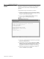
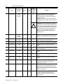
Allen-Bradley
Smart
Self-powered
Serial
Converter
Cat. No. 1203-SSS
Firmware 1.xx
User Manual
Important User Information
Because of the variety of uses for the products described in this publication, those responsible for the application and use of this control
equipment must satisfy themselves that all necessary steps have been
taken to assure that each application and use meets all performance
and safety requirements, including any applicable laws, regulations,
codes and standards.
The illustrations, charts, sample programs and layout examples
shown in this guide are intended solely for purposes of example.
Since there are many variables and requirements associated with any
particular installation, Rockwell Automation does not assume responsibility or liability (to include intellectual property liability) for actual
use based upon the examples shown in this publication.
Rockwell Automation publication SGI-1.1, Safety Guidelines for the
Application, Installation, and Maintenance of Solid-State Control
(available from your local Rockwell Automation office), describes
some important differences between solid-state equipment and electromechanical devices that should be taken into consideration when
applying products such as those described in this publication.
Reproduction of the contents of this copyrighted publication, in
whole or in part, without written permission of Rockwell Automation, is prohibited.
Throughout this manual we use notes to make you aware of safety
considerations:
!
ATTENTION: Identifies information about practices
or circumstances that can lead to personal injury or
death, property damage or economic loss.
Attention statements help you to:
•
Identify a hazard.
•
Avoid the hazard.
•
Recognize the consequences.
Important: Identifies information that is critical for successful application and understanding of the product.
Summary of Changes
Summary of Changes
The information below summarizes the changes made to the company
wide templates since the last release.
Updated Information
No changes have been made to this manual.
Publication 1203-5.14 – September 1998
Summary of Changes
Notes:
Publication 1203-5.14 – September 1998
Table of Contents
Using This Manual
Preface
Objectives . . . . . . . . . . . . . . . . . . . . . . . . . . . . . . . . . . . . . . . . . . . . . . . . . . . . . . . . . .P-1
Who Should Use This Manual?. . . . . . . . . . . . . . . . . . . . . . . . . . . . . . . . . . . . . . . . . .P-1
Purpose of this Manual . . . . . . . . . . . . . . . . . . . . . . . . . . . . . . . . . . . . . . . . . . . . . . . .P-1
Contents of this Manual . . . . . . . . . . . . . . . . . . . . . . . . . . . . . . . . . . . . . . . . . . . . .P-2
Safety Precautions . . . . . . . . . . . . . . . . . . . . . . . . . . . . . . . . . . . . . . . . . . . . . . . . . . .P-2
Terms and Abbreviations . . . . . . . . . . . . . . . . . . . . . . . . . . . . . . . . . . . . . . . . . . . . . .P-3
Conventions Used in this Manual . . . . . . . . . . . . . . . . . . . . . . . . . . . . . . . . . . . . . . . .P-3
Rockwell Automation Support . . . . . . . . . . . . . . . . . . . . . . . . . . . . . . . . . . . . . . . . . . .P-3
Local Product Support . . . . . . . . . . . . . . . . . . . . . . . . . . . . . . . . . . . . . . . . . . . . . .P-3
Technical Product Assistance . . . . . . . . . . . . . . . . . . . . . . . . . . . . . . . . . . . . . . . . .P-4
Overview
Chapter 1
Chapter Objectives . . . . . . . . . . . . . . . . . . . . . . . . . . . . . . . . . . . . . . . . . . . . . . . . . . . 1-1
Overview of the 1203-SSS Converter. . . . . . . . . . . . . . . . . . . . . . . . . . . . . . . . . . . . . 1-1
What Hardware Is Included?. . . . . . . . . . . . . . . . . . . . . . . . . . . . . . . . . . . . . . . . . . . . 1-2
Overview of Setting Up the 1203-SSS Converter . . . . . . . . . . . . . . . . . . . . . . . . . . . . 1-2
Required Tools and Equipment. . . . . . . . . . . . . . . . . . . . . . . . . . . . . . . . . . . . . . . . . . 1-2
Installation
Chapter 2
Chapter Objectives . . . . . . . . . . . . . . . . . . . . . . . . . . . . . . . . . . . . . . . . . . . . . . . . . . . 2-1
Required Tools and Equipment. . . . . . . . . . . . . . . . . . . . . . . . . . . . . . . . . . . . . . . . . . 2-1
Selecting Cables . . . . . . . . . . . . . . . . . . . . . . . . . . . . . . . . . . . . . . . . . . . . . . . . . . . . . 2-1
Installing Your 1203-SSS Converter . . . . . . . . . . . . . . . . . . . . . . . . . . . . . . . . . . . . . . 2-2
Removing the 1203-SSS Converter . . . . . . . . . . . . . . . . . . . . . . . . . . . . . . . . . . . . . .2-3
Configuring the
1203-SSS Converter
Chapter 3
Chapter Objectives . . . . . . . . . . . . . . . . . . . . . . . . . . . . . . . . . . . . . . . . . . . . . . . . . . . 3-1
Factory-Default Settings for the 1203-SSS Converter’s Parameters . . . . . . . . . . . . . 3-1
Required Tools and Equipment. . . . . . . . . . . . . . . . . . . . . . . . . . . . . . . . . . . . . . . . . . 3-1
Establishing a Serial Connection with the 1203-SSS Converter. . . . . . . . . . . . . . . . . 3-1
Using a PC Running Terminal Emulation Software. . . . . . . . . . . . . . . . . . . . . . . . . 3-2
Using a VT100-Compatible Terminal . . . . . . . . . . . . . . . . . . . . . . . . . . . . . . . . . . . 3-6
Navigation Techniques . . . . . . . . . . . . . . . . . . . . . . . . . . . . . . . . . . . . . . . . . . . . . . . . 3-7
Editing Parameters in the 1203-SSS Converter . . . . . . . . . . . . . . . . . . . . . . . . . . . . . 3-8
Displaying and Clearing the Event Queue in the 1203-SSS Converter . . . . . . . . . . . 3-9
Publication 1203-5.14 – September 1998
ii
Table of Contents
Specifications
Appendix A
Appendix Objectives . . . . . . . . . . . . . . . . . . . . . . . . . . . . . . . . . . . . . . . . . . . . . . . . . A-1
Specifications . . . . . . . . . . . . . . . . . . . . . . . . . . . . . . . . . . . . . . . . . . . . . . . . . . . . . . A-1
1203-SSS Converter
Parameters
Appendix B
Appendix Objectives . . . . . . . . . . . . . . . . . . . . . . . . . . . . . . . . . . . . . . . . . . . . . . . . . B-1
Factory-Default Settings . . . . . . . . . . . . . . . . . . . . . . . . . . . . . . . . . . . . . . . . . . . . . . B-1
Parameters . . . . . . . . . . . . . . . . . . . . . . . . . . . . . . . . . . . . . . . . . . . . . . . . . . . . . . . . B-1
Publication 1203-5.14 – September 1998
Preface
Using This Manual
Objectives
Who Should Use This Manual?
Read this preface to become familiar with the rest of the manual. In
this preface, you will read about the following:
•
Who should use this manual.
•
The purpose of this manual.
•
Terms and abbreviations.
•
Conventions used in this manual.
•
Rockwell Automation support.
Use this manual if you are responsible for using the 1203-SSS
converter to install, wire, program, or troubleshoot control systems.
This manual is intended for qualified service personnel responsible
for using the 1203-SSS converter. You must have previous experience
with and a basic understanding of electrical terminology,
programming procedures, required equipment, required software,
networking, and safety precautions.
Purpose of this Manual
This manual is a learning and reference guide for the Smart
Self-powered Serial converter. It describes the procedures needed to
install, configure, and troubleshoot the converter. Before you install,
operate, or configure the converter, you should read this manual in its
entirety.
Publication 1203-5.14 – September 1998
P-2
Using This Manual
Contents of this Manual
This manual contains the following information:
Chapter
Safety Precautions
Contents
Preface
Preface
Describes the purpose, background, and
scope of this manual. Also provides
information on safety precautions and
technical support.
1
Overview
Provides an overview of the 1203-SSS
converter.
2
Installation
Provides procedures for installing the
1203-SSS converter.
3
Configuring the 1203-SSS
Converter
Provides procedures for configuring the
1203-SSS converter, including how to set
up a serial connection to the converter,
navigate in the converter’s software, edit
its parameters, and view its event queue.
A
Specifications
Provides specifications for the 1203-SSS
converter.
B
1203-SSS Converter
Parameters
Provides detailed information on the
1203-SSS converter’s parameters.
Please read the following safety precautions carefully.
!
!
Publication 1203-5.14 – September 1998
Title
ATTENTION: Only personnel familiar with
SCANport devices and the associated machinery should
plan or implement the installation, start-up,
configuration, and subsequent maintenance of the
product using a 1203-SSS converter. Failure to comply
may result in personal injury and/or equipment damage.
ATTENTION: Risk of severe bodily injury or
equipment damage exists. The Comm Flt Action (4)
parameter allows the user to change the default
configuration that would allow the converter and
associated drive to continue to operate if I/O
communication is lost. Precautions should be taken to
assure that your settings for these parameters and your
application do not create a hazard of bodily injury or
equipment damage.
Using This Manual
Terms and Abbreviations
The following terms and abbreviations are specific to this product.
For a complete listing of Allen-Bradley terminology, refer to the
Allen-Bradley Industrial Automation Glossary, Publication AG-7.1.
Term:
Conventions Used in this Manual
P-3
Definition
SCANport™
A standard peripheral communications interface for various
Allen-Bradley drives and power products.
SCANport
Peripheral
A device that provides an interface between SCANport and a
network. It is often referred to as an adapter. For example, the
1203-SSS converter is a SCANport peripheral.
SCANport
Product
A device that uses the SCANport communications interface to
communicate with one or more peripheral devices. For example, a
motor drive such as a 1336 PLUS is a SCANport product.
Smart Selfpowered Serial
converter
In this manual, it is also referred to as the “1203-SSS converter” and
“converter.”
The following conventions are used throughout this manual:
•
Bulleted lists provide information, not procedural steps.
•
Numbered lists provide sequential steps or hierarchical
information.
•
Italic type is used for chapter names and for parameter names.
•
Bold type is used for names of menus, menu options, screens, and
dialog boxes.
Important: This type of paragraph contains tips or notes that have
been added to call attention to useful information.
Rockwell Automation Support
Rockwell Automation offers support services worldwide, with over
75 sales/support offices, over 500 authorized distributors, and over
250 authorized systems integrators located through the United States
alone. In addition, Rockwell Automation representatives are in every
major country in the world.
Local Product Support
Contact your local Rockwell Automation representative for:
•
Sales and order support.
•
Product technical training.
•
Warranty support.
•
Support service agreements.
Publication 1203-5.14 – September 1998
P-4
Using This Manual
Technical Product Assistance
If you need to contact Rockwell Automation for technical assistance,
please review the information in the Troubleshooting chapter first. If
you are still having problems, then call your local Rockwell
Automation representative.
Refer to http://www.ab.com for updates and supporting
documentation.
Publication 1203-5.14 – September 1998
Chapter
1
Overview
Chapter Objectives
Overview of the 1203-SSS
Converter
Chapter 1 provides an overview of your 1203-SSS converter. In this
chapter, you will read about the following:
•
How the 1203-SSS converter works.
•
Parts of the 1203-SSS converter.
•
Required equipment and tools.
The 1203-SSS converter provides a temporary electronic
communications interface between a personal computer with a serial
port and any single SCANport product.
The serial connection to the 1203-SSS uses a full-duplex RS-232 DF1
protocol. This protocol is used by various software packages,
including DriveTools32™ and DriveExplorer™, to connect to
SCANport products.
Figure 1.1
Example of a 1203-SSS Converter Connecting a PC to a SCANport Product
1336 PLUS
1202-C10
SCANport Cable
1203-SFC
Serial Cable
A SCANport cable connects the converter to a SCANport product
through a SCANport port on the SCANport product. A serial cable
connects the converter to the PC through a serial port on the PC.
The 1203-SSS converter receives its power from the connected
SCANport product, so it requires no external power source.
Publication 1203-5.14 – September 1998
1-2
Overview
What Hardware Is Included?
Figure 1.2 and the table below illustrate and list the main parts of the
1203-SSS converter:
Figure 1.2
Parts of the Converter
3
4
2
1
Number
Part
Description
1
RS-232 Serial Port
Provides a connector for a 1203-SFC serial cable.
2
SCANport Connection
Provides a standard SCANport 8-pin circular mini-DIN connector for the SCANport cable.
3
RX LED
Illuminates when data is sent from the host computer to the 1203-SSS.
4
TX LED
Illuminates when data is sent from the 1203-SSS to the host computer.
Not
Shown
1202-C10 SCANport
Cable
SCANport cable (1 m) with male-to-male connections. (Included with the converter.)
Not
Shown
1203-SFC Serial
Cable
Serial cable (2 m) with a locking low profile connector to connect to the converter and a 9-pin
sub-miniature D female connector to connect to the personal computer. (Included with the
converter.)
Overview of Setting Up the
1203-SSS Converter
To set up the 1203-SSS converter, you must perform the following
tasks:
1. Install the converter. Refer to Chapter 2, Installation.
2. If desired, configure the converter’s parameters. Refer to
Chapter 3, Configuring the 1203-SSS Converter.
Required Tools and Equipment
Publication 1203-5.14 – September 1998
To install and configure a 1203-SSS converter, you need the following
equipment:
•
1203-SSS converter.
•
Appropriate cables for SCANport and serial connections. Refer to
Chapter 2, Installation, for more information.
•
A PC running a Windows™ terminal emulation program (e.g.,
HyperTerminal) or DriveExplorer™, or a VT100-compatible
terminal.
Chapter
2
Installation
Chapter Objectives
Required Tools and Equipment
Selecting Cables
Chapter 2 provides the information that you need to install the
1203-SSS converter. In this chapter, you will read about the
following:
•
Tools and equipment needed for the installation.
•
Selecting cables for SCANport and serial connections.
•
Installing the converter.
•
Removing the converter.
To install your 1203-SSS converter, you will need the following:
•
1203-SSS converter.
•
Appropriate cables for SCANport and serial connections. Refer to
the “Selecting Cables” section in this chapter.
To connect the 1203-SSS converter to the SCANport product and
computer, you must use the appropriate SCANport and serial cables.
The 1203-C10 SCANport cable and 1203-SFC serial cable that are
shipped with each converter are all you should need to connect any
SCANport product to a computer.
Important: If you are connecting the converter to a hand-held
personal computer (HPC) or PalmPC running Windows CE™, you
must purchase an additional null cable converter (1203-SNM) or any
standard PC null cable with two male 9-pin sub-miniature D
connectors.
Important: To provide proper termination of the 1203-SFC cable
shield, the chassis of the PC should be properly grounded. If this is
not possible or practical, then a ground wire should be connected to
the 1203-SFC shield at the shell of the 9-pin sub-miniature D
connector.
Publication 1203-5.14 – September 1998
2-2
Installation
Installing Your 1203-SSS Converter
The following instructions explain how to physically install your
1203-SSS converter.
1. Connect the 1203-C10 SCANport cable to the SCANport product
and the converter.
To connect the cable to the converter, align the pins on the cable
with the holes in the SCANport connection and then insert the
SCANport cable. The cable will click into a locked position.
Important: Because the converter receives its power from the
SCANport product, the SCANport product must be powered for the
converter to work.
Figure 2.1
Connecting the SCANport Cable to the Converter
2. Connect the 1203-SSS serial cable to the converter and then to
your PC’s serial port. The cable will click into a locked position.
Figure 2.2
Connecting a Serial Cable to the Converter
Publication 1203-5.14 – September 1998
Installation
2-3
3. While a PC is communicating with the 1203-SSS converter,
verify the converter is sending and receiving data. Refer to the
following table:
Important: You must be transmitting data to a drive for the LEDs to
blink.
LED(s) Viewed:
If:
Cause:
Action:
LEDs are off
The converter is inactive.
1. Ensure data is being transmitted.
2. Ensure that cables are properly connected to the
PC, SCANport product, and converter.
LEDs are blinking
green
The converter is providing an interface between
the PC and the SCANport product.
No action.
LED is off
The converter is not powered.
1. Ensure data is being transmitted.
2. Ensure the SCANport cable is properly
connected and the SCANport product is
powered.
LED is blinking green
Data is flowing from the PC to the converter.
No action.
LED is off
There is a communications problem.
Ensure that the serial port parameters (e.g., data
rate) are properly configured in the PC.
LED is blinking green
Data is flowing from the converter to the PC.
No action.
Both
RX
TX
The converter is now installed. If you wish to configure its parameters
and change its default settings (e.g., baud rate), refer to Chapter 3,
Configuring the 1203-SSS Converter.
Removing the 1203-SSS Converter
If you want to disconnect the 1203-SSS converter, you need to:
!
ATTENTION: Risk of severe bodily injury or
equipment damage exists. If the software application
using the 1203-SSS converter is providing control to the
SCANport product, the SCANport product may fault
when you remove the 1203-SSS converter. Make sure
the application can handle this situation before
removing a 1203-SSS converter that is used for control
purposes.
1. Disconnect the 1203-C10 SCANport cable from the product and
then from the converter.
2. Disconnect the 1203-SFC serial cable from the converter and then
the PC.
Important: To disconnect the SCANport cable, gently push in the
cable and then pull it out.
Publication 1203-5.14 – September 1998
2-4
Installation
Notes:
Publication 1203-5.14 – September 1998
Chapter
3
Configuring the 1203-SSS Converter
Chapter Objectives
Factory-Default Settings for the
1203-SSS Converter’s Parameters
Chapter 3 provides information that you need to configure the
1203-SSS converter. In this chapter, you will read about the
following:
•
1203-SSS converter’s default setting.
•
Equipment needed to make a serial connection to the converter.
•
Connecting either a PC running terminal emulation software or a
VT100-compatible terminal to the converter.
•
Navigating in the converter’s software.
•
Editing the converter’s parameters.
•
Viewing and clearing the converter’s event queue.
The factory-default settings of the 1203-SSS converter enable the
following functions:
•
Node address of 1.
•
Baud rate of 9600.
•
If control data is being transmitted and a time-out occurs, the
SCANport product will be faulted by the converter.
If you wish to change any of these functions you must connect to the
converter and edit its parameters. To do so, refer to:
Required Tools and Equipment
Establishing a Serial Connection
with the 1203-SSS Converter
•
Appendix B, 1203-SSS Converter Parameters, for detailed
information about each of the converter’s parameters.
•
Instructions in this chapter on establishing a serial connection.
•
Instructions in this chapter on how to edit the parameters.
To make a serial connection to the converter, you need the following:
•
1203-SFC serial cable.
•
1203-C10 SCANport cable.
•
A PC running a Windows terminal emulation program
(e.g., HyperTerminal) or DriveExplorer, or a VT100-compatible
terminal.
The converter’s software lets you edit the converter’s parameters and
view its event queue. To access its software, you must make a serial
Publication 1203-5.14 – September 1998
3-2
Configuring the 1203-SSS Converter
connection between the converter and either a PC running terminal
emulation software or a terminal. Refer to the following table:
If Using:
Refer to:
PC running terminal emulation software
page 3-2 in this manual
VT100-compatible terminal
page 3-6 in this manual
DriveExplorer Software
DriveExplorer User Manual, Publication
9303-5.0
Using a PC Running Terminal Emulation Software
A variety of terminal emulation programs can be used to establish a
serial connection to the converter. The following instructions describe
how to establish the initial serial connection to the converter using a
PC running Windows 95 HyperTerminal software. Future connections
to the converter can use this same configuration by clicking the icon
added to the initial screen when the configuration is saved.
Important: If you are not using Windows 95 HyperTerminal, steps to
establish a serial connection may vary from the following steps.
1. Install the 1203-SSS converter by connecting it to the personal
computer and SCANport product. Refer to Chapter 2,
Installation, for more information.
2. In Windows, click Start, select Programs, Accessories, and then
HyperTerminal. A HyperTerminal dialog box appears.
Figure 3.1
Example HyperTerminal Dialog Box
Publication 1203-5.14 – September 1998
Configuring the 1203-SSS Converter
3-3
3. Double-click HyperTrm.exe. The Connection Description
dialog box appears.
Figure 3.2
Example Connection Dialog Box
4. Enter a name in the Name field and select any icon in the Icon
field. In this example, we enter “1203-SSS” in the Name field.
5. Click OK. The Phone Number dialog box appears.
Figure 3.3
Example Phone Number Dialog Box
6. In the Connect Using field, select the appropriate
communications port (usually COM1 or COM2).
Publication 1203-5.14 – September 1998
3-4
Configuring the 1203-SSS Converter
7. Click OK. The Comm Properties dialog box appears.
Figure 3.4
Example Comm Properties Dialog Box
8. Select the following settings:
•
9600 in the Bits per second field.
If you have previously set the converter’s Serial Port Rate (3)
parameter to enable 19200 bps, set the bps to 19200 in this
field.
•
8 in the Data bits field.
•
None in the Parity field.
•
1 in the Stop bits field.
•
None in the Flow Control field.
9. Click OK. A blank HyperTerminal screen appears.
Publication 1203-5.14 – September 1998
Configuring the 1203-SSS Converter
3-5
10. In the File menu, select Properties. The Properties dialog box
appears.
Figure 3.5
Properties Dialog Box
11. Click the Settings tab.
12. In the Function, arrow, and ctrl keys act as box, verify
Terminal keys is selected.
13. In the Emulation field, verify VT100 is selected.
14. Click OK.
15. In the File menu, select Save. The configuration is saved and the
icon you selected will appear in the initial HyperTerminal
window next time you start HyperTerminal.
Important: Next time you need to make a connection to the converter,
double-click the icon just created.
16. Press the Enter key. The main menu of the1203-SSS Serial
Self-powered Serial Converter application appears. Refer to
Figure 3.6.
Publication 1203-5.14 – September 1998
3-6
Configuring the 1203-SSS Converter
Figure 3.6
Main Menu
You now have access to the converter’s software. Refer to the
“Navigation Techniques” section on page 3-7 for more information
on using it.
Using a VT100-Compatible Terminal
Important: If you are using a PC, skip this section.
The following instructions describe how to establish a serial
connection to the converter using a VT100-compatible terminal.
1. Install the 1203-SSS converter by connecting it to the VT100compatible terminal and SCANport product. Refer to Chapter 2,
Installation, for more information.
2. Start your terminal.
3. Select the following settings:
Publication 1203-5.14 – September 1998
•
9600 in the Bits per second field.
If you have previously set the converter’s Serial Port Rate (3)
parameter to enable 19200 bps, set the bps to 19200.
•
8 in the Data bits field.
•
None in the Parity field.
•
1 in the Stop bits field.
•
None in the Flow Control field.
Configuring the 1203-SSS Converter
3-7
4. Press the Enter key. The main menu of the 1203-SSS Smart
Self-powered Serial Converter application appears.
Figure 3.7
Main Menu
You now have access to the converter’s software. Refer to the
“Navigation Techniques” section on page 3-7 for more information
on using it.
Navigation Techniques
To perform any of the functions in the software (e.g., editing
parameters), you need to know the following navigation techniques:
Press:
To
1, 2, 3, 4, 5, 6, 7, 8, 9, 0
Select an option in the Main Menu (1 – 2) or enter a value
for a parameter in the Parameter screen (0 – 9).
Escape
Return to Main Menu or abort changes to a parameter.
Down Arrow
View the next parameter.
Up Arrow
View the previous parameter.
Right Arrow
View the next value for a parameter.
Left Arrow
View the previous value for a parameter.
Enter
Save a value for a parameter.
Publication 1203-5.14 – September 1998
3-8
Configuring the 1203-SSS Converter
Editing Parameters in the 1203-SSS
Converter
The 1203-SSS converter has some configurable parameters. Refer to
Appendix B, 1203-SSS Converter Parameters, for a detailed list. If
you do not want to use the converter’s default settings, edit its
parameters.
To edit parameters using a serial connection, you need to:
1. Establish a serial connection to access the converter’s software.
Refer to the “Establishing a Serial Connection with the 1203-SSS
Converter” section earlier in this chapter.
2. Press 1 to select 1> Display Setup Parameters. The first
parameter appears on the bottom of the screen.
Figure 3.8
Example Display Parameters Screen
3. If necessary, scroll through the list of parameters by pressing the
Up Arrow or Down Arrow key.
4. Edit parameters as necessary using the Left Arrow and Right
Arrow keys. Refer to the “Navigation Techniques” section earlier
in this chapter for information on changing values. Refer to
Appendix B, 1203-SSS Converter Parameters, for valid values.
5. Reset power to the converter by setting the Reset Adapter (5)
parameter to Enable and pressing Enter.
Publication 1203-5.14 – September 1998
Configuring the 1203-SSS Converter
Displaying and Clearing the Event
Queue in the 1203-SSS Converter
3-9
If an unexpected problem occurs with the converter, you may need to
check the event queue to view events that have happened in the
converter. Follow these instructions:
1. Establish a serial connection to access the converter’s software.
Refer to the “Establishing a Serial Connection with the 1203-SSS
Converter” section earlier in this chapter.
2. Press 2 to select 2> Display event queue. The event queue
appears.
Figure 3.9
Example Event Queue
3. Scroll through the list of Event Queue parameters by pressing the
Up Arrow or Down Arrow key.
Number
1
2–7
Name
Description
Clr Event Queue
Enable = Clears the event queue.
Ready = Leaves the event queue as is.
Event Queue 1 – Event Queue 6
Event in the event queue. Most recent event is listed in Event Queue 1.
4. If desired, clear the event queue in the adapter by setting Clr
Event Queue (1) to Enable and pressing the Enter key.
5. Press the Escape key to return to the main menu.
Publication 1203-5.14 – September 1998
3-10
Configuring the 1203-SSS Converter
Notes:
Publication 1203-5.14 – September 1998
Appendix
A
Specifications
Appendix Objectives
Appendix A provides the specifications that you may need to install
or use your 1203-SSS converter.
Specifications
The following table gives the specifications for the 1203-SSS
converter.
Category
Specifications
Dimensions
4.08 x 2.89 x 0.93 in (103.5 x 73.4 x 23.6 mm)
Weight
2.5 oz. (0.09 g)
Operating Temperature
0 to +50°C (32 to 122°F)
Storage Temperature
-40 to +85°C (-40 to 185°F)
Relative Humidity (Operating)
5 to 95% non-condensing
Relative Humidity (Non-Operating)
5 to 95% non-condensing
Shock (Operating)
30g peak acceleration, 11(+/-1)ms pulse width
Shock (Non-Operating)
50g peak acceleration, 11(+/-1)ms pulse width
Vibration (Operating)
2.5g @5Hz-2KHz
Vibration (Non-Operating)
5g @5Hz-2KHz
Power Consumption
60mA at +12V DC
Regulatory Compliance
UL 508C and CUL
The 1203-SSS converter is a non-repairable unit.
Publication 1203-5.14 – September 1998
A-2
Specifications
Notes:
Publication 1203-5.14 – September 1998
Appendix
B
1203-SSS Converter Parameters
Appendix Objectives
Appendix B provides information on the 1203-SSS converter’s
parameters. In this appendix, you will read about the following:
Factory-Default Settings
•
Factory-default settings for the converter.
•
Parameters in the converter.
The factory-default settings of the 1203-SSS converter enable the
following functions:
•
Node address of 1.
•
Baud rate of 9600.
•
If control data is being transmitted and a time-out occurs, the
SCANport product will be faulted by the converter.
If you wish to change any of these functions you must connect to the
converter and edit its parameters. To do so, refer to:
Parameters
•
The “Parameters” section in this chapter for detailed information
about each of the converter’s parameters.
•
Instructions in Chapter 3, Configuring the 1203-SSS Converter,
on establishing a serial connection.
•
Instructions in Chapter 3, Configuring the 1203-SSS Converter,
on how to edit parameters.
The following table provides information on the parameters for the
1203-SSS converter.
Default
Writable
Reset or
Power Cycle
to Take
Effect
#
Name
Valid Values/
Settings
1
SCANport Adapter
0–7
0
No
No
Identifies the port number to which the converter is
connected on the SCANport product.
2
DF-1 Address
0 – 254
1
Yes
Yes
Provides the node address for the 1203-SSS converter.
3
Serial Port Rate
9600
19200
9600
Yes
Yes
Sets the baud rate for the 1203-SSS converter’s serial/DF1
port.
Important: If you change the baud rate in the converter, you
must also change it in your terminal emulation software or
terminal.
Description
Important: For information on editing parameters, refer to Chapter 3, Configuring the 1203-SSS Converter.
Publication 1203-5.14 – September 1998
B-2
1203-SSS Converter Parameters
#
Name
4
Comm Flt Action
Valid Values/
Settings
Fault
Zero Data
Hold Last
Default
Writable
Reset or
Power Cycle
to Take
Effect
Fault
Yes
No
!
Description
Determines the action the converter should instruct the
SCANport product to take if the converter detects a
communication problem. This parameter is active only if
control I/O is enabled.
Important: If you change the value of this parameter, the
user application may not be able to control the product after
a fault.
ATTENTION: Risk of severe bodily injury or equipment
damage exists. The Comm Flt Action (4) parameter allows
the user to change the default configuration that would allow
the converter and associated drive to continue to operate if
communication is lost. Precautions should be taken to
assure that your settings for these parameters and your
application do not create a hazard of bodily injury or
equipment damage.
5
Reset Adapter
Ready
Enable
Set Defaults
Ready
Yes
No
Enable = Resets the converter.
Set Defaults = Sets all parameters to their default values.
6
Clear DF1 Counts
Ready
Enable
Ready
Yes
No
Ready = No action.
Enable = Clears all DF-1 statistical parameters.
7
DF1 Packets Sent
0 – 65535
0
No
No
Reports the number of DF-1 packets sent by the converter.
8
DF1 Packets Rcvd
0 – 65535
0
No
No
Reports the number of DF-1 packets received by the
converter.
9
Undelivered Msgs
0 – 65535
0
No
No
Reports the total number of DF-1 messages that were sent
but never acknowledged.
10
ENQs Sent
0 – 65535
0
No
No
Reports the number of ENQ characters sent by the
converter.
11
ENQ Received
0 – 65535
0
No
No
Reports the number of ENQ characters received by the
converter.
12
NAKs Received
0 – 65535
0
No
No
Reports the number of NAK characters received by the
converter.
13
NAK Bad Packet
0 – 65535
0
No
No
Reports the number of NAKs sent by the converter because
of corrupt packets (improper protocol messages) as
determined by the converter.
14
NAK No Memory
0 – 65535
0
No
No
Reports the number of NAKs sent by the converter because
the converter ran out of memory to buffer the incoming
messages. The converter will run out of memory when the
previous command has not completed and there is no place
to save the new commands.
15
Duplicate Msgs
0 – 65535
0
No
No
Reports the number of duplicate messages sent by the
converter. This value contains the total number of
consecutive messages received by this device with the
same TNS number.
Important: For information on editing parameters, refer to Chapter 3, Configuring the 1203-SSS Converter.
Publication 1203-5.14 – September 1998
Index
Numerics
1203-SSS converter
editing parameters 3-8
event queue 3-9
function 1-1
hardware 1-2
illustration 1-2
installation 2-1 to 2-3
parameters 3-1, 3-8, B-1 to B-2
removal 2-3
resetting B-2
serial connection to 3-1
setting up 1-2
software 3-7
E
equipment required 1-2
installation 2-1
serial connection 3-1
event queue 3-9
H
HyperTerminal 3-2
I
installing the 1203-SSS converter 2-1 to 2-3
M
A
audience for this manual P-1
B
baud rate
parameter B-1
setting in converter using a terminal 3-6
setting in converter using terminal emulation
software 3-4
manual
audience P-1
contents P-2
conventions P-3
purpose P-1
N
navigation techniques in software 3-7
P
C
cables
SCANport
connecting to the converter 2-2
disconnecting from the converter 2-3
serial
connecting to the converter 2-2
disconnecting from the converter 2-3
Publication 1203-5.14 - September 1998
I–1
parameters
default settings 3-1
editing 3-8
list of B-1 to B-2
R
removing the 1203-SSS converter 2-3
resetting the 1203-SSS converter B-2
I–2
Index
S
safety precautions P-2
SCANport
cables 2-2, 2-3
definition P-3
peripherals P-3
products P-3
serial cables 2-2, 2-3
serial connection
cable 3-1
using a PC running terminal
emulation software 3-2 to 3-5
using a VT100-compatible
terminal 3-6 to 3-7
serial port rate, refer to baud rate
specifications A-1
Publication 1203-5.14 - September 1998
T
technical support P-3
terminal 3-6
terminal emulation software 3-2
terms and abbreviations P-3
tools, refer to equipment
We Want Our Manuals to be the Best!
You can help! Our manuals must meet the needs of you, the user. This is your opportunity to make sure they do just that.
By filling out this form you can help us provide the most useful, thorough, and accurate manuals available. Please take a
few minutes to tell us what you think - then mail this form or FAX it.
FAX: your local Allen-Bradley Sales Office or 414/512-8579
PUBLICATION NAME _________________________________________________________________________________________________
PUBLICATION NUMBER, DATE AND PART NUMBER (IF PRESENT) __________________________________________________________
✔ CHECK THE FUNCTION THAT MOST CLEARLY DESCRIBES YOUR JOB.
❏ SUGGEST/RESPONSIBLE FOR THE PURCHASE OF EQUIPMENT
❏ MAINTAIN/OPERATE PROGRAMMABLE MACHINERY
❏ DESIGN/IMPLEMENT ELECTRICAL SYSTEMS
❏ TRAIN/EDUCATE MACHINE USERS
❏ SUPERVISE FLOOR OPERATIONS
✔ WHAT LEVEL OF EXPERIENCE DO YOU HAVE WITH EACH OF THE FOLLOWING PRODUCTS?
NONE
LITTLE
MODERATE
EXTENSIVE
PROGRAMMABLE CONTROL
❏
❏
❏
❏
AC/DC DRIVES
❏
❏
❏
❏
PERSONAL COMPUTERS
❏
❏
❏
❏
NC/CNC CONTROLS
❏
❏
❏
❏
DATA COMMUNICATIONS/LAN
❏
❏
❏
❏
✔ RATE THE OVERALL QUALITY OF THIS MANUAL BY CIRCLING YOUR RESPONSE BELOW. (1) = POOR (5) = EXCELLENT
HELPFULNESS OF INDEX/TABLE OF CONTENTS
1
2
3
4
5
CLARITY
1
2
3
4
5
EASE OF USE
1
2
3
4
5
ACCURACY AND COMPLETENESS
1
2
3
4
5
QUALITY COMPARED TO OTHER COMPANIES’ MANUALS
1
2
3
4
5
QUALITY COMPARED TO OTHER ALLEN-BRADLEY MANUALS
1
2
3
4
5
✔ WHAT DID YOU LIKE MOST ABOUT THIS MANUAL?
✔ WHAT DID YOU LIKE LEAST ABOUT THIS MANUAL?
CUT ALONG DOTTED LINE
✁
✔ PLEASE LIST ANY ERRORS YOU FOUND IN THIS MANUAL (REFERENCE PAGE, TABLE, OR FIGURE NUMBERS).
✔ DO YOU HAVE ANY ADDITIONAL COMMENTS?
✔ COMPLETE THE FOLLOWING.
NAME __________________________________________________________________________ COMPANY_____________________________________________________________________________
TITLE _________________________________________________ DEPARTMENT________________________________________________
STREET _______________________________________________ CITY _______________________ STATE ______ ZIP
____________________
TELEPHONE ___________________________________________ DATE _______________________________________________________
FOLD HERE
FOLD HERE
NO POSTAGE
NECESSARY
IF MAILED
IN THE
UNITED STATES
BUSINESS REPLY MAIL
FIRST CLASS
PERMIT NO. 413
MEQUON, WI
POSTAGE WILL BE PAID BY ADDRESSEE
ALLEN-BRADLEY
Attn: Marketing Communications
P.O. Box 760
Mequon, WI 53092-9907
1336 FORCE, 1336 IMPACT, DriveExplorer, DriveTools32, and SCANport are trademarks of Rockwell International, Inc.
Windows 95, Windows CE, Windows NT, and Microsoft are either registered trademarks or trademarks of Microsoft Corporation.
Allen-Bradley, a Rockwell Automation Business, has been helping its customers improve
productivity and quality for more than 90 years. We design, manufacture and support a broad range
of automation products worldwide. They include logic processors, power and motion control devices,
operator interfaces, sensors and a variety of software. Rockwell is one of the world’s leading
technology companies.
Worldwide representation.
Argentina • Australia • Austria • Bahrain • Belgium • Brazil • Bulgaria • Canada • Chile • China, PRC • Colombia • Costa Rica • Croatia • Cyprus • Czech Republic • Denmark •
Ecuador • Egypt • El Salvador • Finland • France • Germany • Greece • Guatemala • Honduras • Hong Kong • Hungary • Iceland • India • Indonesia • Ireland • Israel • Italy •
Jamaica • Japan • Jordan • Korea • Kuwait • Lebanon • Malaysia • Mexico • Netherlands • New Zealand • Norway • Pakistan • Peru • Philippines • Poland • Portugal • Puerto
Rico • Qatar • Romania • Russia-CIS • Saudi Arabia • Singapore • Slovakia • Slovenia • South Africa, Republic • Spain • Sweden • Switzerland • Taiwan • Thailand • Turkey •
United Arab Emirates • United Kingdom • United States • Uruguay • Venezuela • Yugoslavia
Allen-Bradley Headquarters, 1201 South Second Street, Milwaukee, WI 53204 USA, Tel: (1) 414 382-2000 Fax: (1) 414 382-4444
Publication 1203-5.14 – September 1998
PN 191166 (01)
Copyright 1998 Allen-Bradley Company, Inc.
Printed in USA