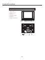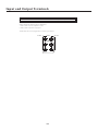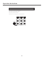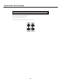
1
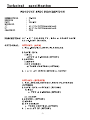
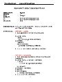
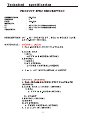
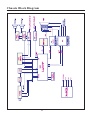
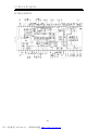
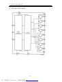
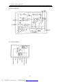
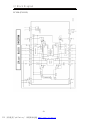
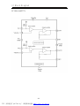
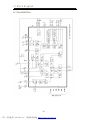
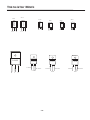
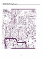
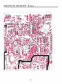
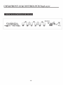
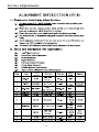
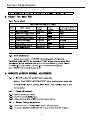
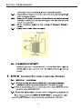
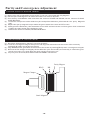
SERVICE MANUAL
3Y18 CHASSIS
Design and specifications are subject to change without prior notice.
( ONLY REFERRENCE)
_____
ENGINEER BY:
_____
CHECKED BY:
PPROVED BY:
_____
Contents
Safety Notice--------------------------------------------------------2
Technical specification--------------------------------------------3-8
Chassis Block Diagram--------------------------------------------9
IC Block Diagram -------------------------------------------------10-15
Transistor mark ----------------------------------------------------16
PCB Top/Bottom layer -------------------------------------------17-19
Service Adjustments ------------------------------------------- 20-24
Purity and Convergence Adjustment ----------------------------25
Control Location ---------------------------------------------------26
Input and Output Terminals----------------------------------------27
Operation Instructions------------------------------------------28-35
Mechanical Disassemblies----------------------------------------36
Circuit Diagram-----------------------------------------------------37
Safety Notice
SAFETY PRECAUTIONS
1:An isolation transformer should be connected in the power line between the receiver and
the AC line when a service is performed on the primary of the converter transformer of the
set.
2:Comply with all caution and safety-related notes provided on the cabinet back, inside the
cabinet, on the chassis or the picture tube.
3:When replacing a chassis in the cabinet, always be certain that all the protective devices
are installed properly,such as,control knobs, adjustment covers or shields, barriers,isolation resistor-capacitor networks etc.. Before returning any television to the customer,the
service technician must be sure that it is completely safe to operate without danger of
electrical shock.
X-RADIATION PRECAUTION
The primary source of X-RADIATION in television receiver is the picture tube. The picture
tube is specially constructed to limit X-RADIATION emissions. For continued X-RADIATION
protection, the replacement tube must be the same type as the original including suffix
letter. Excessive high voltage may produce potentially hazardous X-RADIATION. To avoid
such hazards, the high voltage must be maintained within specified limit. Refer to this
service manual, high voltage adjustment for specific high voltage limit. If high voltage exceeds specfied limits, take necessary corrective action. Carefully follow the instructions for
+B1 volt power supply adjustment, and high voltage check to maintain the high voltage
within the specified limits.
PRODUCT SAFETY NOTICE
Product safety should be considered when a component replacement is made in any area
of a receiver. Components indicated by mark ! in the parts list and the schematic diagram
designate components in which safety can be of special significance. It is particularly
recommended that only parts designated on the parts list in this manual be used for component replacement designated by mark ! . No deviations fromresistance wattage or voltage ratings may be made for replacement items designated by mark ! .
-2-
-3-
-4-
-5-
-6-
-7-
-8-
Chassis Block Diagram
-9-
IC B lock D iagram
IC 201 (LA7693*)
-10PDF 文件使用 "pdfFactory" 试用版本创建 www.fineprint.com.cn
IC B lock D iagram
IC 702 & 802 (HEF 4052B)
-11PDF 文件使用 "pdfFactory" 试用版本创建 www.fineprint.com.cn
IC B lock D iagram
IC500 (CQ0765)
IC 301(LA7804* )
-12PDF 文件使用 "pdfFactory" 试用版本创建 www.fineprint.com.cn
IC B lock D iagram
IC 801 (LV1115)
-13PDF 文件使用 "pdfFactory" 试用版本创建 www.fineprint.com.cn
IC B lock D iagram
IC 901 (LA42***)
-14PDF 文件使用 "pdfFactory" 试用版本创建 www.fineprint.com.cn
IC B lock D iagram
IC 701(AN5832SA)
-15PDF 文件使用 "pdfFactory" 试用版本创建 www.fineprint.com.cn
Transistor Mark
NPN
PNP
PNP
L7809
INPUT
B
C
E
E C
B
E C
C27 17
D2499
C18 15
E C
B
A1015
C21 20
C24 82
A966
E C B
E C
B
NPN
NPN
PNP
B
B E C
L7812
OUTPUT
GND
INPUT
OUTPUT
GND
-16-
L7805
INPUT
OUTPUT
GND
Service Adjustments
-20-
Service Adjustments
-21-
Service Adjustments
-22-
Service Adjustments
-23-
Service Adjustments
-24-
Purity and Convergence Adjustment
COLOR PURITY ADJUSTMENT
(1) Before color purity adjustment,warm up the TV set over 15 minutes and fully degauss.
(2) Receive pure white signal in AV status and set the TV receiver dynamic.
(3) Go to factory mod MENU2. After write down the values of R-BIAS and B-BIAS, set the values of R-BIAS
and B-BIAS zero.
(4) Loosen the clamp screw of the deflection yoke and pull the deflection yoke towards color purity Magnetic
loop.
(5) Adjust color purity magnetic loop to make the green area at the center of CRT screen.
(6) Slowly push the deflection yoke toward the front of CRT and set it where a uniform green field is obtained.
Tighten the clamp screw of the deflection yoke.
(7) Restore the values of R-BIAS,G-BIAS AND B-BIAS.
CONVERGENCE ADJUSTMENT
(1) Receive a dotted pattern. Set the TV receiver dynamic.
(2) Loose the convergence magnet clamperrrrr and align red with blu dots at the center of the screen by
rotating(R,B) static convergence magnets.
(3) Align Red/Blue with green dots at the center of the screen by rotating(RB-G) static convergence magnet.
(4) Remove the DY wedges and slightly tilt the deflection yoke horizontally and vertically to obtain the good
overall convergnce. Fix them after the goob overall convergence got.
(5) Fix purity error is found,follow PURITY ADJUSTMENT instructions.
Purity Magnet
RB-G
Magnet Clamper
Static Magnet
-25-
RB
Control Location
CONTROL LOCATION
1.
2.
3.
4.
5.
6.
7.
8.
9.
10.
11.
12.
Power (Standby) Button
Standby Indicator
Remote Control Sensor
Speakers
Side AV In (Option)
Menu Button
Channel Down / Up Button
Volume Down / Up Button
AV/TV Button
AC Power Cord
Audio/Video - In/Out (Option)
Antenna Input Socket (75 ohm)
5
4
7
7 8
8
6 9
11
10
-26-
3
2 1
12
4
Input and Output Terminals
INPUT AND OUTPUT TERMINALS (OPTION)
VIDEO AND AUDIO INPUT/OUTPUT TERMINALS
1. Video / Audio input for playback for VCR.
2. Video / Audio output for TV program.
*Please keep AC cord unplugged when connecting TV system.
AV OUT
VIDEO
AUDIO
LEFT
LEFT
RIGHT
RIGHT
-27-
AV IN 2
Operation Instructions
INPUT AND OUTPUT TERMINALS (OPTION)
VIDEO AND AUDIO INPUT/OUTPUT TERMINALS
1. Video / Audio input for playback for VCR.
2. Video / Audio output for TV program.
*Please keep AC cord unplugged when connecting TV system.
YCbCr IN
AV OUT
AV IN 2
Y
VIDEO
VIDEO
Cb
LEFT
LEFT
Cr
RIGHT
RIGHT
S-VIDEO
-28-
Operation Instructions
INPUT AND OUTPUT TERMINALS (OPTION)
VIDEO AND AUDIO INPUT/OUTPUT TERMINALS
1. Video / Audio input for playback for VCR.
2. Video / Audio output for TV program.
*Please keep AC cord unplugged when connecting TV system.
AV OUT
AV IN 2
AUDIO
AUDIO
VIDEO
VIDEO
-29-
Operation Instructions
OPERATION INSTRUCTIONS
Turn the TV set on, then power indicator will light up. Press the program up or down button on the TV
set,or press the on/off button on the remote control.The picture will appear after a few seconds . (If tuned
on) The program number is displayed on the top right-hand corner of the screen.
MENU BUTTON
1.Press this button to select menu. PICTURE, SOUND, PRESET, TIME and SYSTEM can be selected
cyclically.
Picture Menu
Sound Menu
Features Menu
Timer Menu
Install Menu
Exit
2.After enters each menu, you can select the item which you will adjust by PROG.+/- buttons, and adjust
this item by VOL. +/- buttons.
*The item which you select will change blue.
Picture menu
PICTURE
CONTRAST
BRIGHTNESS
COLOR
SHARPNESS
TINT
54
55
60
50
00
Sound menu (Option)
SOUND
VOLUME
TREBLE
BASS
BALANCE
SURROUND
SOUND MODE
10
00
00
00
OFF
USER
You can select CONTRAST, BRIGHTNESS, COLOR, SHARPNESS, and TINT
item by PROG.+/- Buttons , and adjust the item which you select by
VOL.+/- Buttons.
*TINT is displayed only for NTSC and is not available for PAL or SECAM.
In this menu you can adjust the tone of the TV output.
1. VOLUME
In this item,you can control the magnitude of the speakers output.
2.TREBLE
You can change the treble of thespeakers output.
3. BASS
You can change the bass of the speakers output.
4.BALANCE
You can control the balance of the two speakers output.
5.SURROUND
You can get the surround effect by turning this item on.
6. SOUND MODE
You can select present sount mode in this item.
-30-
Operation Instructions
OPERATION INSTRUCTIONS
Features menu
FEATURES
LANGUAGE
ENGLISH
COLOUR SYS
AUTO
C.C
OFF
PARENTAL CTRL ON
CALENDAR
GAME
Timer menu
TIMER
TIME
START TIME
STOP TIME
CH SWITCH
SWITCH TO
_ _:_ _
_ _:_ _
_ _:_ _
_ _:_ _
___
Install menu
INSTALL
PROG NO
SKIP
RECEPTION
FINE
AFT
AUTO STORE
01
ADD
AIR
ON
1. LANGUAGE
You can change language menu in this item.
2. COLOUR SYS
You can change present color system in this item.
3.C.C
Set the CCD OFF or ON.
4.PARENTAL CTRL
Input the password 1980 to call up V-CHIP, MPAA and TVPG item.
5.CALENDAR
(1)press VOL+ button to enter into CALENDAR menu.
(2)press VOL+ button to select YEAR. MONTHOR DATE, and press VOL+/button to adjust them.
6.GAME(Option)
You can play the game on TV.
1. TIME
You can adjust the currently time by this item. Press the VOL+button set
hour , and the VOL-button set minute .
2. START TIME
Set the time when the TV set turn on .
3.STOP TIME
Set the time when the TV set turn off .
4.CH SWITCH
Set the time when channel replace.
5.SWITCH TO
Set the program to switch to when the switch timer expires.
1. PROG NO
In this item, you can store the channel number which are watching, and change
the channel number by VOL.+/- Buttons (or number keys).
2. SKIP
You can set "ON" by VOL.+/- Buttons if you want to cancel the channel number
which you are watching.
3.RECEPTION
You can select AIR¡¢CATV-STD¡¢CATV-IRC or CATV-HRC.
4. FINE
If fine item is selected, frequency data is fine tuned in upward or downward by
the VOL.+/-buttons.
5. ATF
You can select on or off.
6. AUTO STORE
Press VOL.+/- Buttons, then the TV set will automatically search from V-L band
to band.
-31-
Operation Instructions
OPERATION INSTRUCTIONS
SELECTING PROGRAM
Use 0-9 digit buttons to call directly on the program number that you want. If you want to select a double digits
program number , firstly press "- / - -" button, then input the two digits.
Program number can also be changed by "PROGRAM DOWN" and "PROGRAM UP" buttons. Press
"PROGRAM UP" button, program number will increase. Press "PROGRAM DOWN" button, program number
will decrease.
CHILD LOCKED
The TV set can provide the locked key for control or prevent your children from watching the program.
SET CHILD LOCKED:
Press the "LOCK" button on remote unit.The key locked (
) is displayed on the screen. Then the
symbol will disappear after five seconds and enter child locked mode. You can't use any key on the TV set.
RELEASE CHILD LOCKED:
You can cancel this mode by pressing the 'LOCK" button again.
-32-
Operation Instructions
LOCATION OF CONTROL (REMOTE HANDSET UNIT)
STAND BY BUTTON (
)
Press this button to turn the TV on/off. Press any Number
Button or Program Up/Down Button, picture and sound will
come on within a few seconds.
2
3
4
5
6
7
8
9
--/---
0
AV/TV
MUTE BUTTON (
)
Press once to mute the sound, press again to return to
previously set sound level.
SOUND SYSTEM BUTTON (SYS.)
Press this button to select the correct sound system.
5.5M
4.5M
6.5M
6.0M
PROG.+
VOL.-
MENU
VOL.+
PROG.CCD
V-CHIP
Q.VIEW
P.P.
PROGRAM SELECTION BUTTONS (0-9, -/--)
Push the number for your desired program and the
program indicator will be displayed on the screen.
Press -/-- key to select one digit or two digit entry, to select
program 0-9, use one digit entry, to select 10-99 use two
digits entry.
Press number key 0-99 for program selection.
MTS
LOCK
SCAN
PROGRAM UP/DOWN BUTTON (PROG. +/-)
Press the Program Up Button to select the program
forwards.
Press the Program Down Button to select the program
backwards.
-33-
Operation Instructions
LOCATION OF CONTROL (REMOTE HANDSET UNIT)
VOLUME UP/DOWN BUTTONS (VOL.+/-)
Press Volume Up/Down Buttons to adjust sound level.
PERSONAL PRESETS BUTTON (P.P.)
You can select DYNAMIC, MILD, COLORFUL, STANDARD and CUSTOM by pressing this button.
RECALL BUTTON (
)
Press this button sequentially to recall for the program number, color system and sound system on the
screen.
SLEEP BUTTON (
)
This key is used to set the sleep timer in 15 minutes step up to two hours. When the preset time runs to 0.
TV set will go into stand by mode. To switch off this function, press this key step by step until " --" is
displayed on the screen.
LOCK BUTTON
The key is to prevent a child watching the TV, please refer to page 5 for the details.
QUICK VIEW BUTTON (Q.VIEW)
Press this button to return to the previously viewed program.
AV/TV BUTTON
Press this button to display external video signal such as VCR or CD video player. AV will be displayed on
the screen. Press this button again to switch back to TV signal from AV.
MENU BUTTON (MENU)
Use "MENU" button for tuning procedure, please refer to page 4-5 for the details.
SCAN BUTTON
Press this button , you can automatically browse the every channels which you have .
MTS BUTTON
Press the MTS button, you can select MONO¡¢STEREO¡¢SAP if this
Program signal hare been STEREO and SAP sigal.
CCD BUTTON
Press the "CCD" button you can enter the CCD menu.
V-CHIP BUTTON
Press the "V-CHIP" button you can enter the V-CHIP menu.
-34-
Operation Instructions
BATTERY INSTALLATION (REMOTE CONTROL UNIT)
1. Remove the battery cover.
2. Insert the 2 UM4-AAA 1.5V batteries making sure the polarity (+ or -) of the batteries matches the
polarity marks inside the unit.
3. Replace the battery cover.
Replace with new batteries when the TV set begins to show the following symptoms:
Operation is unsteady or erratic. Sometimes the TV set does not function with Remote Control
Unit.
Remark:
1) Alkaline Batterie Recommended
2) Remove batteries when they are exhausted or if the remote control is not to be used for a long time.
THE CAUSES OF INTERFERENCE
Incorporated in your TV receiver are the most upto-date devices to eliminate interference. Local
radiation however, can create disturbances which
visibly affect your picture. Proper installation, a
good aerial are your best safe-guards against
these disturbances.
RF INTERFERENCE
Moving ripples across the screen are caused by
nearby transmitting or receiving-short-wave radio
equipment.
DIATHERMY
Herringbone pattern and partial picture loss can
result from the operation of diathermy equipment
from a nearby doctor's surgery or hospital.
SNOW
Weak TV signals from long distant stations result
in an instead picture and give the effect of falling
snow. An antenna adjustment or antenna
amplifier may be needed.
GHOST
Multiple image caused by TV signals reflected
back from surrounding buildings, hills, aircraft, etc.
is minimized by correct aerial positioning.
CAR IGNITION
Nearby cars and electrical motors can cause small
streaks across the picture or make the picture roll.
-35-
Mechanica
l Disassemblies
CABINETBACKREMOVAL
CHASSISREMOVAL
1.Refert o Figure 1,remove7screws.
2.Pulloffcabine t back andremove.
1.Removecabinetback.
2.Dischargethepicturetubeanode(2ndanodelead)tothe
dagcoating(picturetubegroundinglead).
3.DisconnectDegaussingcoilsocket(KE),Picturetubesocket,
D eflectionyokeconnector(KDY),Speakerconnectors(KL
andKR),and2ndanodelead.
4.Removechassiscompletelybyslidingitstraightback.
PICTURE
TUBE
REMOVAL
CAUTION:
Donotdisturbthedeflectionyoke
ormagnetassemblyo n th e pictur e tube
Neck.Car e mus t be takentokee p these
assembliesintact,unles
s pictur e tub e is
beingreplaced.Dischargethepicturetube
tothecoatingbeforehandingth
e Tube.
Figure1.CabinetBackRemovel
1.Removechassis,referringtoChassisRemovalinstructions.
2.Placecabinetfron t facedownonthesoftsurface.
3.Removethescrewoneachcornerofthepicturetubeand
GENTLYliftthepicturetubeoutofthecabinet.
4.Installareplacementpictur e tubeinreverseorder.
Properl y instal l thedegaussingcoilandpicturetube
groundin g leadonthepicturetube.SeeFigure2.
Note:IfthePictureTubeisbeingreplaced,mountthe
DegaussingCoi l onthepicturetube.Seefollowing..
DEGAUSSING
COIL
DEGAUSSING
COILHOLDER
PICTURETUBE
GROUNDINGLEAD
DEGAUSSING
COILSOCKET
ToCRTUnit
ground
-36-
A
B
C
D
C101
1 50V
14
XS502
XS502
AGC
6
13
10u
C601
1K
R605
10u
75
AV-IN
10u
C606
FU501
T2.5A 250V~
R501
2.2M
2
SDA
*
8
7
6
5
4
3
2
1
1
2
3
TV
AV2
GND
C609
16V 1u
3
C504
4n7
REM
Q601
C
AV1
GND
C508
560 1KV
1
9V
AV2
GND
*
YUV
L
AV1
AV2
AV1
TV
R
VCC
IC501
L502
L502
C607
10u/16V
R608
470
C608
16V 1u
9
10
11
12
13
14
15
9V
16
C612
16V 10u
YUV
IC601
SDA
C506
4n7
D501
D501
C505
C525 4n7
470pF 250V~
1
3
4
R502
4.5
2
C503
4n7
C501
0.1
1
L501
C524
470pF 250V~
2
PTC
C502
0.1
V1
IR
GND
RPM
R
AV1/AV2
E
Q602
*
C613
16V 10u
VCC
Cb
Cr
DR
SCL
75
RT501
R607
DL
R1
DR
DL V1
R1
AS
L1
SCL
Y-DVD
R606
75
R604
75
V1
L1
S-Y
R603
C605
10u
C604
10u
C603
10u
C602
12
10
8
2
4
16
18
20
C526
0.1
7
14
11
9
3
5
17
19
21
75
R602
R101
47K
S-C
3
XS501
12
1
15
13
XS601
75
R601
7
C611
10u
C510
0.022
D503
3.6V
C509 C512
47u 50V 0.1
R610
SW-2
SW-2
A?
SW-2
A?
SW-2
A?
SW-2
A?
C507
150uF 400V
KACQ0565RT
5V-1
CH+
CH-
VOL+
VOL-
MENU
SW-2
A?
A?
C511
3300
D502
IN4148
R505
330
R506
680
D504
4148
1
1
D505
IN4148
R507
10
R503
1/2W 110K
R504
1/2W 110K
C202 C203 C204
0.022 39pF 1u
R201
39K
3
4
*
3
1
5
7
6
*
8
*
10
*
C101
220
T501
T501
C523
2n2 400V~
R509
8M2
IC502
12V R101
L201
22uH
C201
18P
Z201
*
Q101
C2717
C108
0.01
L101 R107
56uH 220
C107
0.01
R240
560
R239
680
*
15
*
12
16
1
1
C
C209
100u
1
5V-2
R508 1K
C517
100u 160V
C514
1n 1KV
C519
220u 35V
12V
R230 R229
24K 24K
R231
560
Q202
A1015
R247
2M2
R208
220
R527
100K
R512
30K
R522
3K9
IC503
7805
R513
180K
1
RP501
1K
2
12V
C234
10V 47u
C229
18p
Cb
G202 C230
0.1
*
R516
5K1 1/4W
R104
2W 10K
R514
10K
B
Q507
C1815
C215
0.47u
C214
0.47
R515
5K6
R514
10K
C246
0.1
R526
5K1 1/4W
B
R510
24K
B+
B
Q507
C1815
3
5V-1
27V
IC302
7812
IC504
D510
TL431
R511 TBY56J
4K7 1/4W
2
R517 C527
5K6 10n
R521
10K
Q501
966
R521
10K
Q501
966
1
1
R207
1K
R522
3K9
A IN
C228
0.1
C231 R232
0.047 100
C210 C211
C212
0.01 100u 16V 10V 100u
5V-2
L203
68uH
C213
10u
JUMPERC
IC503
7805
A OUT
D508
FR103
D509
TBY56J
1
C513
680
C239
50V 1u
C208
1500
R204
10K
C207
0.01
C515
680
Q201
2SC1815
C236
0.47
D507
FR103
C521
470u 16V
E
*
9
13
2
R236
10K
R203 C206
330 0.022
10
1
12V
23
24
9
L2
R2
V2
G
150K
R609
560
R
DL2
5V-1
AV/TV
10u
C610
1
2
3
4
5
B
11
R108
560
5V-2
C226
47pF
LA76938
IC201
32V
R211
C218 220
10V 330u
C216
0.015
21
BT/LOCK
32V
XS604
R110
100
R105
5K6
C106
0.01
22
2
5V-2
2
C225 C222
10V 100u
0.033
R212
3K
C217
1u
FBP
R224
100
R225
47K
C227
1u
C224 C223 R223
0.01 50V 2.21M
R215
4K7
R214
4K7
IC802
LA42352
C822 100
R220
4K7
FIL
R
R 2W
2
2
1
XS602
1
1
3
3
4
4
V
L
R
OUT
L
IN
R
Cr
Cb
Y
V
4
R102
100
R622
270
KEY
5
R103
100
TV-R
B
R618
10k
R619
1K
RO
R621
1K
1
4
6
R620
10k
1
BP
3
3
1
C102
220
TV-L
R623
75
4
R106
1K2
C
IF1
3
VIF IN 1 64
1
2
LO
2
4
AV1
5
R109
27
1 SIF OUT
2
1
4 64
E
1
VIF IN 2 63
2 VIF AGC
5 63
AGC
2
59
AV2
2
2 1
1
0.01
62
IF GND 62 C237
3 SIF IN
0.022
C205
61
RF AGC 61
4 FM FIL
4
3
R202
1K
FM
60
5 FM/A OUT
5
AFT FIL 59
6 A OUT
6
V OUT 60
R237
47K
R238
47K
POWER OFF MUTE
B
R234
1K
C238
50V 2.2u
57
B L D FIL 57
8 IF VCC
AV-IN
9
56 R233 680K
10V 470u C233
V IN/S-C IN 56
58
APC FIL 58
7 SIF APC FIL
7
R616 R617
1.5K 680
R611 R612 R613 R614 R615
27K 8.2K 4.7K 3.9K 2.7K
1
2
2
8
C243
50V 1u
9 VM
1
3
2
22uH L202
0.01
C232
55
V/C/D VCC 55
10 ABL
10
53
C APC 53
12 R OUT
12
R
54
AV IN 54
11 RGB VCC
D507
4148
Cr
14
B
11
1
50
V OUT
C235
0.47
52
V OUT/FSC 52
13 G OUT
51
CR 51
14 B OUT
13
C
E
Q505
C1815
R405 1.5K
VD101
upc574
G
C
E
C528
47u 160V
49
16
4.43M 50
15 E/W
15
CB 49
16 V RAMPOSC
4K7R210
C242
10V 220u
C
E
17
FAST 48
R406 1.5K
L IN R806
FAST
3.9K
R
47
1
17 V OUT
48
LV1115
IC801
R213 1/4W 5K1
R242
68K 18
3
R406 1.5K
C801 1
C802 4.7
4
C803
B
45
B-IN 45
3.9K
20
5
20 H AFC
R IN R807
19
6
20
G
18
7
R227
20K
FBP IN 44
R405 1.5K
R-IN 47
18 VCO IREF
17
8
C804
C805
C806
C807
R801
3.6K
R228
100
CCD VCC 43
22 GND
21 H OUT
21
46
G-IN 46
19 H VCC
19
16
44
15
42
CPU GND 42
23 AV1/AV2
23
43
14
C813 4.7
C812 1
R804 100
R803 100
13
10
47
9
AV1
41
5600P
0.01
2700P
0.1
0.1
4.7
11
47
C811
C810
12
1
C808
C809
22
SCL
40
RESET 40
25 POW
25
PLL 41
24 TV/AV
24
TV/AV
SDA
KEY
39
1K
C244
0.01
R241
15K
1K
R802
R705
IN1
AV2
R243
10K
R217
4K7
R216
4K7
R245
10K
37
1
AV1
38
27
KEY 39
2
C823 1
GND
04-12-23
IN2
5V-1
R246 C245
10K 0.1
L204
68uH
C253
R221 10V
100u
10k
AV2
SDA1
LA42352
3
C221
15p
G201
*
R222
A?
390K
*
C220
15p
20V
R219
100
R218
100
3
X-RAY
5 SDA
6 SCL
7 TEST
8 VCC
A2
A1
A0
IC202
24C08
4
3
2
1
B
Q301
2SC2383
GND
C240
0.01
C250
10V 100u
36
SCART 36
29 TUNER
29
BAND1 37
28 X-RAY
28
VOL2
35
VDD 35
P16 PWM3
30 MUTE
30
BAND2 38
27 VOL
3
STB
5
R407
1K
4
C824 1
SCART
R414
1K
6
C826
470
C825
470
34
SDA1 31
NC
9
GND
10
NC
5V-2
9V
B
PIN5
R
G
B
R
SPEAK
Q403
C1815
27V
C307
35V 10
C306
390p
5
4
3
2
1
12V
2
SPEAK
S801
S802
16V 470u
1
C828
2
1
16V 470u
C827
NPN2
1015
R302
2K7
C305
820
OUT1
12
VOL1
13
VCC
7
XT2 34
31 P12/SDA1
1
R330
5.1K
C333
1000
27V
1
*
2
1
1
VCC
V302
TT2140
9V
PUMP
R311
8K2
R324
1/ 1W
R513
8.6K
B
D903
4148
R907
150
2
1
Q901
2482
R902
1.5K
1
R905
1.5K
R908
1.5K
Q903
2482
B
D313
S5295G
C324
10u 50V
R327
33K
C332
1
*
1
2
2
2
R319
10K
R309
10
C332
2200
D301
S5295J
C338
250V 4u7
C303
22u 250V
R301
22K
C339
400V 0.33
D306
4148
C323
680p
1
OUTPUT OUT VCC NON IN
2
B
B
R910
10K
Q904
C1815
GND
G
R
Q902
2482
2
C310 C311
3n3 5n6
C309
470 2KV
R312
C325
100u 16V 4K3
B
D902
4148
R904
150
1
2
IC301
LA78040
C904
470
D901
4148
R901
150
VD308 C332
BA158 220U 35V
R327
12K
INV IN
D307
HZ7C2
Q303
B
C1815Y
R313
4K7
T302
XR0961
VD510
4148
4
3
1
2
3
4
9V
5
XS901
R
D904
4148
B
1
1
1
C
R903
390
C
2E
1
C
OUT2
8
33
XT1 33
SCL1
26 PO3/INT3
REM
26
REM
C
E
32 P13/SCL1
32
VD202
5C1
VD203
5C1
R416
10K
R417
10K
R911
270
R407
1K
SCL1
3
E2
1
4
R327
2.2K
11
C
E
R332
220
2
R327
12K
C901
470
C902
470
C903
470
5
4
4
XS902
B+
Date:
File:
D
Size
Title
C302
680p
2
10
1
9
4
3
5
6
7
*
2
8
6
3
5
C326
100n
R305
1k
1
3
5
6
HV
8
*
200V
XS302
*
Revision
1
2
3
4
SCREEN
FOCUS
HV
G901
CRT
XS301
C304
56n
*
L303
L302
T301
R316
1W 1K
1W
R315
1W 1K
1W
10
C905
1000
7
*
A
B
C
D
11-Mar-2006
Sheet of
By: UOC\SANYO UOC电原理图\SANYO UOC 电原理图(LA1115).DDB
F:\F 盘\机芯系列\三洋(sanyo)\SANYODrawn
OUC\保迪
Number
R1
R >3W
R304
10 1W
R308
1 1W
12V
R
G
2 B
2
2
R914 2.7K
R913 2.7K
R912 2.7K
1
1
1
1
E
2
1
C
E
2
1
6
2W
R906
390
R909
390
7
C327
1u 16V
VD204
HZ5C1
R418
1.8K
3W
C
E
2W
R915
12K
R916
12K
R917
12K
2W
R320
3K
9
3
R317
180 1/2W
2
1
10
4
C821 1
C820 1
C819 4.7
C818 0.068
C817 0.1
C816 2700P
C815 0.1
R805
3.6K
C814 0.1
C104
4u7/50V
C
E
R415
4.7K
R514 R515
8.2K 2K
2
1
1
3
2W
t
1
3W
1W
1W