1
J
J
SERVICE
MANUAL
MODEL 1080 A MONITOR
PN 314041-02
,
TM
4}
IT
MODEL 1080 A MONITOR
PN 314041-02
n
n
n
n
n
Commodore-Amiga, Inc.
1200 Wilson Drive, West Chester, Pennsylvania 19380 U.S.A.
Commodore-Amiga makes no expressed or implied
warranties with regard to the information contain
ed herein. The information is made available sole
ly on an as is basis, and the entire risk as to quality
and accuracy is with the user. Commodore-Amiga
Inc. shall not be liable for any consequential or in
cidental damages in connection with the use of the
information contained herein. The listing of any
available replacement part herein does not con
stitute in any case a recommendation, warranty or
guaranty as to quality or suitability of such replace
ment part. Reproduction or use without express
ed permission, of editorial or pictorial content, in
any matter is prohibited.
n
This manual contains copyrighted and proprietary information. No part
of this publication may be reproduced, stored in a retrieval system, or
transmitted in any form or by any means, electronic, mechanical,
photocopying, recording or otherwise, without the prior written permis
sion of Commodore-Amiga Inc.
Copyright © 1986 by Commodore-Amiga Inc.
All rights reserved.
u
TABLE OF CONTENTS
PAGE
1.
SPECIFICATIONS
1
2.
X-RAY RADIATION PRECAUTION
2
3.
SAFETY PRECAUTION
2
4.
PRODUCT SAFETY NOTICE
2
5.
SERVICE NOTES . . .
2
6.
LOCATION FOR USER CONTROLS
3
7.
CHASSIS VIEW
8.
MECHANICAL DISASSEMBLY
9.
10.
u
4
5, 6
BLOCK DIAGRAM
7
PARTS LAYOUT
8, 9
11.
INSTALLATION AND SERVICE ADJUSTMENTS
12.
HIGH VOLTAGE CHECK
10~13
13
13.
FS CIRCUIT CHECK
14.
TROUBLESHOOTING CHARTS
14~21
15.
CHASSIS REPLACEMENT PARTS LIST
22-27
13
16.
PRINTED CIRCUIT BOARD VIEW
28, 29
17.
SCHEMATIC DIAGRAM
30,31
CRT
13", 90°, 0.39 mm Dot (Nonglare, grey)
Power Input
AC 120V, 60 Hz
Power Consumption
70W Typ.
Input Signals
NTSC Comp./Sep. video/Digital RGBI/
Analog RGB
Input Levels
Comp.: 1Vp-p , 75 ohms, Termination
Digital RGBI
:
TTL levels
Analog RGB
:
0.7Vp-p
1.0Vp-p
Audio Output
LOW
Video Bandwidth
NTSC
:
4.2 MHz
Scanning Frequency
Display Format
Display Size
Digital RGBI
:
15.32 MHz
Analog RGB
:
10 MHz
Horizontal
15.75 KHz
Vertical
60 Hz
U
LJ
Q
RGBI mode
: 2000 Characters
(80 col. x 25 I ines, 6 x 7 dot array)
Video mode
: 1000 Characters
(40 col. x 25 I ines, 6x7 dot array)
RGBI mode
250 mm
Horizontal
Vertical
Resolution
u
U
1. SPECIFICATIONS
Audio Input
0
182 mm
RGBI mode
:
Horizontal
2000 Characters
640 dots
400 lines (interlaced)
Vertical
Video mode
Horizontal
Vertical
:
1000 Characters
320 dots
Dimensions
400 lines (interlaced)
360 (W) x 327.5 (H) x 376 (D) mm
Weight
11.5 kg
—
1
—
U
U
U
u
2. X-RAY RADIATION PRECAUTION
1. Excessive high voltage can produce potentially hazard
ous X-RAY RADIATION. To avoid such hazards, the
n
increases abnormally. Each time the color monitor is
serviced, the FS circuit must be checked to determine
that the circuit is properly functioning, following the
FS CIRCUIT CHECK procedure on page 13 of this
high voltage must not be above the specified limit. The
nominal value of the high voltage of this color monitor
is 26.5 kV at zero beam current (minimum brightness)
under a 120V AC power source. The high voltage must
not, under any circumstances exceed 27.5 kV.
Each time a color monitor requires servicing, the high
voltage should be checked following the HIGH VOLT
manual.
3. The only source of X-RAY RADIATION in this color
monitor is the picture tube. For continued X-RAY
RADIATION protection, the replacement tube must
be exactly the same type tube as specified in the parts
list.
4. Some parts in this color monitor have special safetyrelated characteristics for X-RAY RADIATION protec
tion. For continued safety, parts replacement should
be undertaken only after referring to the PRODUCT
SAFETY NOTICE below.
AGE CHECK procedure on page 13 of this manual. It
is recommended that the reading of the high voltage be
recorded as part of the service record. It is important
to use an accurate and reliable high voltage meter.
2. This color monitor is equipped with a Fail Safe (FS)
circuit which prevents the color monitor from produc
ing an excessively high voltage even if the B+ voltage
3. SAFETY PRECAUTION
n
Connect a 1500 ohm 10 watt resistor, paralleled by a
0.15 mfd, AC type capacitor, between a known good
earth ground (water pipe, conduit, etc.) and the ex
posed metallic parts, one at a time. Measure the AC
voltage across the combination of 1500 ohm resistor
and 0.15 mfd capacitor. Reverse the AC plug at the
AC plug at the AC outlet and repeat AC voltage mea
surements for each exposed metallic part. Voltage
measured must not exceed 1.5 volts RMS. This corre
sponds to 1.0 milliamp, AC. Any value exceeding this
limit constitutes a potential shock hazard and must be
corrected immediately.
WARNING: Service should not be attempted by anyone
unfamiliar with the necessary precautions on this color
monitor. The following are the necessary precautions to
be observed before servicing this chassis.
1. Always discharge the picture tube anode to the CRT
conductive coating before handling the picture tube.
The picture tube is highly evacuated and if broken,
glass fragments will be violently expelled. Use shatter
n
n
proof goggles and keep picture tube away from the un
protected body while handling.
2. When replacing a chassis in the cabinet, always be cer
tain that all the protective devices are put back in place,
such as: non-metallic control knobs, insulating covers,
shields, isolation resistor-capacitor network etc.
3. Before return ing the set to the customer, always perform
an AC leakage current check on the exposed metallic
parts of the cabinet, such as terminals, screwheads,
metal overlays, control shafts etc., to be sure the set is
safe to operate without danger of electrical shock. Plug
AC VOLTMETER
the AC line cord directly into a 120V AC outlet (do
not use a line isolation transformer during this check).
Use an AC voltmeter having 5000 ohms per volt or
more sensitivity in the following manner:
Place this probe on
each exposed
Good earth ground
metallic part.
such as a water
pipe, conduit, etc.
n
n
1500 ohm
10 watts
4. PRODUCT SAFETY NOTICE
Many electrical and mechanical parts in this chassis have special safety-related characteristics. These characteristics are
often passed unnoticed by a visual inspection and the protection afforded by them cannot necessarily be obtained by
using replacement components rated for higher voltage, wattage, etc. Replacement parts which have these special safety
characteristics are identified in this manual and its supplements; electrical components having such features are identified
by shading on the schematic diagram and the parts list.
n
n
Before replacing any of these components, read the parts list in this manual carefully. The use of substitute replacement
parts which do not have the same safety characteristics as specified in the parts list may create shock, fire, X-ray radia
tion or other hazards.
5. SERVICE NOTES
1. When replacing parts or circuit boards, clamp the lead wires to terminals before soldering.
2. When replacing a high wattage resistor (oxide metal film resistor) on circuit board, keep the resistor 10 mm (1/2 in.) away
from circuit board.
3. Keep wires away from high voltage or high temperature components.
n
—
2
—
6. LOCATION FOR USER CONTROLS
u
Q
Front View
im^^^i^m^m^i^^^J^^^^^^
Q
H. Position
V. Hold
0
Color
Tint
Bright
Contrast
Volume
Video Mode Switch (Comp./Sep./RGB)
0
Q
Rear View
0
a
Q
Q
Audio/Video/Chroma IN
0
—
3
Q
n
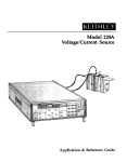
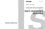
7. CHASSIS VIEW
n
n
n
n
n
CRT DRIVE
BOARD
n
VIDEO BOARD
HEADPHONE
JACK BOARD
/ AC RECEPTACLE
n
n
Figure 1. Chassis View
—
4
—
CZJ
EH
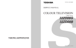
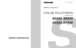
REAR COVER REMOVAL
2. Remove the screws "B" and "C".
3. Slightly open the rear cover, then remove
the speaker connecting socket (a) .
1. Remove the screws "A".
Figure 2-1. Mechanical Disassembly
CD
m
C/>
O
m
■
00
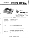
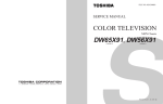
Figure 2-2. Mechanical Disassembly
(Video Terminal Board)
P101
9. BLOCK DIAGRAM
u
BUFFER
2SC752GYorO
2SCl8l5Yor 0x4
CRT
E297IB22
GTHT(MIYZ)
u
u
u
0
0
LJ
D
0
BUFFER
2SCI8l5Yor 0
0
CONVERTER
AC
120V
TRANS
TPW3055A
u
2SA I0I5Y
—
7
ERROR AMP
—
u
10. PARTS LAYOUT
n
H
n
r
n
MAIN BOARD PW5253
Figure 3.
n
n
—
8
—
TERMINAL BOARD PW5252-3
Figure 4.
CRT DRIVE BOARD PW5252-2
Figure 5.
HEADPHONE BOARD PW5252-4
Figure 7.
P820 LED
VIDEO BOARD PW5252-1
Figure 6.
LED BOARD PW5252-5
Figure 8.
—
9
—
0
n
WARNING: BEFORE SERVICING THIS CHASSIS, READ THE "X-RAY RADIATION PRECAUTION," "SAFETY
PRECAUTION" AND "PRODUCT SAFETY NOTICE" ON PAGE 2 OF THIS MANUAL.
n
11. INSTALLATION AND SERVICE ADJUSTMENTS
H
n
n
n
HORIZONTAL HOLD ADJUSTMENT
HORIZONTAL AMPLITUDE ADJUSTMENT
(1)
(2)
Connect the color monitor to a white pattern signal.
Set the brightness control to maximum.
[NOTE] This adjustment must always be preceded by
horizontal hold adjustment, horizontal position
main board to terminal Q^Q.
(1)
(3) Using a short jumper, connect terminal (J) of the
(4) Turn the H. HOLD control (R451) and set it where
the white pattern picture stops (i.e. there is no hori
zontal bar).
(5)
Remove the short jumper.
Connect the color monitor to a white pattern signal.
(2) Set the brightness control to click point.
(3) Turn V. HOLD control (R351) and set it to the center
of vertical hold range.
n
HORIZONTAL POSITION ADJUSTMENT
n
(1) Connect the color monitor to a white pattern signal.
(2) Set the brightness control to click point.
[NOTE] This adjustment must always be preceded by
horizontal hold adjustment.
n
n
(3) Turn the H. POSITION control (R452) to ensure that
an equal space can be obtained on the right and left
sides of the screen.
VERTICAL POSITION ADJUSTMENT
[NOTE] This adjustment must always be preceded by
vertical hold adjustment.
(1) Connect the color monitor to a white pattern signal.
(2) Set the brightness control to click point.
(3) Turn the V. POSITION control (R353) to ensure that
an equal space can be obtained at the top and bottom
of the screen.
n
n
n
signal.
(2) Set the brightness control to click point.
(3) Turn the H. WIDTH coil (L403) until H =250±6mm.
VERTICAL AMPLITUDE ADJUSTMENT
VERTICAL HOLD ADJUSTMENT
(1)
adjustment.
Connect the color monitor to an "H" character pattern
— 10 —
[NOTE] This adjustment must always be preceded by
vertical hold adjustment and vertical picture
position adjustment.
(1) Connect the color monitor to a white pattern signal.
(2) Set the brightness control to click point.
(3) Turn the V. HEIGHT control (R352) until the picture
height equals 182±5 mm.
FOCUS ADJUSTMENT
SUB-BRIGHTNESS ADJUSTMENT
(1) Connect the color monitor to an "H" character signal.
(2) Turn the focus control to obtain the best focus in the
portion between the center and the left top corner of
2. Set the CONTRAST and BRIGHTNESS controls to
1. Connect the monitor to a black pattern signal.
click position.
the display area.
■ NTSC Composite
1. Set the switch (S201) to COMP.
2. Set the COLOR control to minimum.
WHITE BALANCE ADJUSTMENT
3. Adjust the COMPO SUB-BRIGHTNESS (R255) so that
■ NTSC Composite
1. Set the switch (S201) to COMP.
2. Connect the monitor to a white pattern signal of
the raster is slightly visible.
■ RGB
composite.
1. Set the switch (S201) to RGB and (S101) to Analog
3. Set the COLOR control to minimum.
RGB.
4. Turn the SCREEN control (on T461) fully counter
2. Adjust the RGB SUB-BRIGHTNESS (R256) so that
clockwise.
the raster is slightly visible.
5. Set the service switch at SERVICE.
6. Turn the RGB CUTOFF controls (R556, R558, R559)
to obtain each CRT cathode voltage (KR, KG, KB)
will be 100V DC using a high impedance voltmeter.
7. Slowly turn the SCREEN control clockwise until any
two horizontal coldr bars appear.
8. Turn the CUTOFF controls counterclockwise so that
two horizontal color bars of RGB (in the statement 7)
3. Connect the monitor to an "H" character signal (2000
cha.).
4. Mount a brightness meter to the center of display area.
5. Adjust the SUB CONTRAST control (R252) to obtain
38 ft-L.
6. Set the switch (S101) to Digital RGBI.
7. Connect the monitor to an "H" character signal (2000
cha.).
disappear.
8. Mount a. brightness meter to the center of display area.
9. Adjust the SUB CONTRAST control (R250) to obtain
9. Turn the SCREEN control clockwise again until the
third horizontal color bar appears.
10. Adjust the first and second color CUTOFF controls
so that the horizontal color bar will be white.
11. If the white horizontal bar is glittering, turn the
SCREEN control counterclockwise until the bar glit
38 ft-L.
CONVERGENCE MAGNET ASSEMBLY
POSITIONING
Convergence magnet assembly and rubber wedges need
ters slightly.
12. Set the service switch at NORMAL position.
13. Set the BRIGHTNESS and CONTRAST controls to
maximum.
14. Adjust the GREEN and BLUE DRIVE controls
(R555, R557) to obtain proper white balanced picture
in high light area.
15. Rotate the BRIGHTNESS and CONTRAST controls
to obtain dark gray raster. Then check the white
balance in low brightness. If the white balance is not
mechanical positioning. Refer to figure 9.
COLOR PURITY ADJUSTMENT
1. Allow the system to receive a white pattern signal.
2. Turn the CONTRAST and BRIGHTNESS controls to
the maximum.
3. Preheat more than 30 minutes.
4. Using the degausser coil, degauss the picture tube.
5. Loosen the clamp screw of the yoke and slide the
proper, adjust the CUTOFF controls (only two CUT
OFF controls in the statement 10.) to obtain proper
6.
7.
8.
9.
white balanced picture in low light area.
16. Check the white balance again. If it's not good, re
touch the CUTOFF controls and DRIVE controls to
obtain a good white balance in both low and high
light areas.
yoke backward.
Remove the Rubber Wedges.
Slide yoke toward the picture tube.
Receive green raster pattern signal.
Rotate and spread the tabs of the purity magnet (See
Figure 11.) around the neck of the picture tube until
impurity area at four corners are equal.
10. Viewing the screen, slide the yoke backwards until
the complete screen presents a uniform green color.
11. With the yoke remaining in the position (10), check
that the screen presents a uniform red color and a
■ RGB
1. This adjustment must always be preceded by white
balance adjustment of composite.
2. Set the switch (S201) to RGB and (S101) to Analog
uniform
blue color, respectively by Red and Blue
raster pattern signal.
12. Viewing the screen, turn the yoke and tighten the
RGB.
3. Connect the monitor to a white pattern signal of Analog
RGB.
4. Adjust the GREEN and BLUE CUTOFF controls
(R253, R251) so as a good white balance in both low
and high light areas.
clamp screw of the yoke, when the picture becomes
horizontal.
13. Proceed with convergence adjustment.
Differential
coil
Deflection yoke
-Temporary
mounting
Glass cloth tape
mm
Rubber wedge
CRT base
t Rubber wedge
location
Purity convergence
Figure 9.
magnet assembly
Figure 10.
— ■11
—
Adhesive
n
CONVERGENCE ADJUSTMENTS
[NOTE] Before attempting any convergence adjustments,
■ Circumference Convergence Adjustment
the color monitor should be operated for at least
fifteen minutes.
[NOTE] This adjustment requires Rubber Wedges and
Glass Cloth Tapes.
■ Center Convergence Adjustment
1. Place a wedge as shown in figure 10 temporarily.
1. Allow the system to receive a crossbar pattern signal.
2. Adjust the BRIGHTNESS and CONTRAST controls
2. Tilt front of the deflection yoke up or down to obtain
better convergence of YH on top and bottom then ad
just differential coil of deflection yoke to obtain better
convergence of XV on left and right. (See figure 13.)
Push the mounted wedge into the space between the
picture tube and the yoke to hold the yoke temporarily.
for well defined pattern.
3. Adjust two tabs of the 4-Pole Magnets to change the
angle between them (See figure 12) and superimpose
^>ed and blue vertical lines in the center area of the pic
ture screen. (See figure 13.)
4. Turn both tabs at the same time keeping the constant
3. Place other wedge into bottom space.
4. Tilt front of the yoke right or left to obtain better con
angle to superimpose red and blue horizontal lines at
vergence in circumference. (See figure 13.)
the center of the screen. (See figure 12.)
5. Adjust two tabs of 6-Pole Magnets to superimpose red/
blue line with green one. Adjusting the angle affects
the vertical lines and rotating both magnets affects the
horizontal lines.
6. Repeat adjustments 3, 4, 5, keeping in mind red, green
and blue movement, because 4-Pole Magnets and 6-Pole
Magnets interact and make dot movement complex.
5. Hold
the yoke position and put another wedge in
either upper space. Place the wedge on the picture
tube to hold the yoke.
6. Detach the temporarily mounted wedge and put it in.
another upper space. Place it on the picture tube to
fix the yoke.
7. After placing three wedges, recheck overall conver
gence. Tighten the screw firmly to hold the yoke tightly
in place.
8. Stick three glass cloth tapes on wedges as shown in
figure 10.
6-Pole magnets
Adjust the angle
(Vertical lines)
4-Pole magnets
Fixed
Rotate two tabs
at the same time
(Horizontal lines)
Purity magnet
Convergence magnet assembly
Adjustment of magnets
Figure 12.
Figure 11.
BLU
BLU
1—
RED/BLU
RED
—*
GRN
RED/BLU
-»^_W ^ ~ -1
GRN
RED-
4-Pole Magnets Movement
'\
6-Pole Magnets Movement
•R G
BTilt the Yoke up (or down)
Tilt the Yoke right (or left)
Circumference Convergence by DEF Yoke
Center Convergence by Convergence Magnets
Figure 13. Dot Movement Pattern
— 12 —
u
COLOR SYNC. ALIGNMENT
1. Apply a color bar signal and warm up for five minutes.
2. Connect a capacitor (0.47 mfd) between terminal TP-42
and the junction of C204 and C205.
3. Connect a resistor (1k ohm) between pin 13 of IC501
6. Remove the capacitor and the resistor.
7. Check that the color sync, is stable with signal and
power on-off operation. If the color is slow to appear or
the color sync, is out of order, retouch the color sync,
variable capacitor (C551) for proper color monitor.
and +11 volt source line.
4. Set the controls as follows:
CONTRAST: Minimum
u
0
SUB COLOR-SUB TINT ADJUSTMENT
TINT: Click
COLOR: Maximum
5. Adjust the color sync, variable capacitor (C551) on the
Main Board so that the color bar pattern stands still or
drifts slowly across the picture screen.
1. Apply a rainbow color signal of composite.
2. Set the CONTRAST, COLOR and TINT controls to
click position.
3. Adjust the SUB TINT (R553) and SUB COLOR (R554)
controls to obtain a good tint and color respectively.
12. HIGH VOLTAGE CHECK
3. High voltage shall be below 27.5kV.
4. Rotate the BRIGHTNESS control to both extremes
to be sure the high voltage does not exceed the limit
CAUTION: There is no HIGH VOLTAGE ADJUSTMENT
on this chassis. The +115 volt power supply must be
properly adjusted to insure the correct high voltage.
1. Connect an accurate high voltage meter to the second
anode of the picture tube.
2. Turn on the color monitor. Set the BRIGHTNESS and
U
13. FS CIRCUIT CHECK
0
The Fail Safe (FS) circuit check is indispensable for the
final check in the servicing. Checking should be done
2. Temporarily short TP-@ and TP-© on Main board
with a jumper wire. Raster and sound will disappear.
Q
(27.5kV) under any conditions.
CONTRAST controls to minimum (zero beam current).
following the steps below.
1. Turn the power switch on and adjust customer controls
for normal operation.
Q
Check that the monitor returns to normal operation
when pin 23 of IC501 on the Main Board is grounded
with jumper wire.
3. The color monitor must remain in this state even after
removing the jumper wire. This indicates that the FS
circuit is functioning properly.
4. To obtain a picture again, temporarily turn the color
monitor off and allow the FS circuit more than 30
U
Yes
No
seconds to reset. Then turn the power switch on to
Check if the voltage across capacitor
produce a normal picture.
C407 exceed 24V
Faulty
Power Circ uit
or Horizon tal
FS circuit
Circuit
The FS circuit samples horizontal pulses should the high
voltage rise above normal limits. The FS circuit activates
and prevents excessive anode voltage from being developed.
Yes
Defective Fail Safe Circuit
— 13 —
0
No
14. TROUBLESHOOTING CHARTS
n
POWER CIRCUIT
Measure voltage of
115V on power board
n
Too low or too high
r
OV
Check Error Amp
circuit Q804, D814
OK
Check fuse F802
etc.
n
n
NG
NG
Check AC fuse and
R803
ReDlace fuse and
turn power switch on
OK
n
Check Horizontal
circuit
OK
NG
Check/Replace
D801 ~ D804, Q801
End
Check if v<Dltage of
C809 is ap prox. 160V
No
Yes
Check Rectifier
circuit and wiring
Voltage
Take away D806 and
checkc voltage
appears
OV
n
:1
Check over voltage
protector D806
D813,etc.
— 14 —
Check> D818and PWM
circui t Q802, Q803 etc
u
NO RASTER
Check if heater of
CRT is lighting?
1Mo
No
Yes
Is pulse of approx.
25Vp-p presented
at #9 of FBT?
Yes
Check R920
DT
andC RT
Is voltage of CRT
G2 approx. 600V?
No
Is voltage at #2
of FBT 115V?
Yes
Yes
J
lsHosc&
H drive
normal?
No
No
No
Is voltage of CRT
G3 approx. 7kV?
Is R427 open?
Yes
u
Yes
u
Yes
No
Check focus pack
and CRT
Check CRT
Check power circuit
Check
Hout Tr
and FBT
Check H osc
and H drive
u
u
NO VERTICAL SYNC.
u
No
Is picture stabilized
by rotating R351?
u
LJ
Yes
1
Check V. HOLD
circuit and Q501
Check sync,
circuit and Q501
U
LJ
— 15
U
NO HORIZONTAL SYNC.
Is picture stabilized
by rotating R451?
n
No
Check Hold
circuit and
Q501
Yes
Is sync, pulse
lOVp-p presented
at #37 of Q501 ?
n
n
Yes
No
Check Sync.
Circuit and
Q501
Check AFC
circuit and
Q501
NO VERTICAL SWEEP
No
Is power +■ 42V
applied?
Yes
Is sawtooth
waveform presented
at #30 of Q501?
n
No
Check V. HOLD
circuit and
Yes
0501
Is sawtooth wave
No
form presented
at#28ofQ501?
i
Check Height
circuit and
Q501
Yes
r
Check Vert, out
circuit
n
n
n
— 16 —
u
u
NO RASTER (SOUND OK) - NTSC COMPOSITE
0
Heater Elements of CRT
are lit?
Yes
No
Check H.V. at 2nd
Anode of CRT
Check Heater pulse at
#9 of T461
u
No
OK
c leek the DC voltages
at
+ 16.5V line
No
,
OK
Check/Replace Horiz.
Output Trans. T461
Check/Replace
Horiz. Output
Trans 461
No
Check/Re place
Wiring an d Fusible
Resistor F3920
OK
Check the DC voltage
at the pin 19 20 21 of
Q501 (TYP. 7V)
Check/Replace
D403, D409,
R428, R438
Still no raster
I
Replace CRT
V901 (heater open)
u
0
u
No
OK
Check/Replace
Q505, Q506, Q507,
Q508, Q509, Q510,
Q511,Q512,Q513,
Q514,Q515f Q516
Check/Replace
Q501
u
LJ
U
LJ
LJ
U
— 17 —
U
n
n
NO PICTURE AND NORMAL SOUND - NTSC COMPOSITE
Touch ground lead of volt/ohm meter (Rx2 ohm range)
for very short time to pin 6 of Q501
A click noise appears?
(Connect positive lead to chassis ground)
Yes
n
No
\
Turn contrast control:
Screen brightness varies?
n
Check/Replace
Signal Input Board Circuit
Q124,Q125#Q126
No
Yes
n
n
Short for* a moment between
emitter and base of Q208
Raster appears?
Measure voltage at pin 6 of
Q501
2-3V?
No
Yes
i
n
No
Check/Replace
Q126,D122
Yes
Check/Replace
Video amp circuit
Q208
i
Connect capacitor (CT.047 juF)
between pin 6 and pin 4 of Q501
Picture appears?
No
n
Yes
Check/Replace
Q501
Connect capacitor (0.047./iF)
between pin 7 and pin 4 of
Q501
Picture appears?
No
Yes
n
Check/Replace
X201
Check/Replace
Q501
n
n
n
— 18 —
Check/FReplace
Q501
0
NO PICTURE - RGB (NTSC COMPO OK)
Check the DC voltages
at 5V line
NG
OK
Check/Replace
Check the DC voltages
at the emitter of Q104
0
0
Q105, Q106
4~6V?
NG
OK
Check/Replace
Check the DC voltages
at #8, #10, #12 of Q108
Changing the input signal
from White to Black,
change the voltages?
Q104,Q105,Q106
NG
OK
0
D
U
Check/Replace
Q101
Lead Wire (M108, M109)
Check/Replace
Q109,Q114,Q115,
Q116
D
U
NO RASTER - RGB (NTSC COMPO OK)
0
Turn RGB
Sub-Brightness
(R256)
OK
NG
Check the DC
voltages at 12V
line
Adjust RGB
Sub-Brightness
(R256)
NG
OK
Check/Replace
Q118, D112, D124
D125, D126, D127
Check the DC voltages
at #14, #17, #20 of
Q121,6~7V?
NG
Check/Replace
Q121,Q119,
Q120
— 19 —
n
i
NO COLOR
•—
NTSC COMPOSITE
Short between Pin 13
of Q501 and + 12V line
Normal color
Abnormal
n
r
]
i
Check the voltage at
each Pin of Q501
Connect capacitor
(0.047 juF) between
TP41 and TP42
Normal
\
Abnormal
\
Replace Q501
r
Check Color Sync.
Circuit
Check/Replace
Horiz. Pulse
Circuit
r
No signal
No color
\ 1
Normal
Check/Replace
R239, C204,
C215, L204,
Q122, Q123
Check/Replace
Color Control
Circuit
r
Abnormal
\
Replace Q501
Check/Replace
Color Sync. Circuit
{Adjust Color Sync.)
with C551
Replace Q501
n
SPECIFIC TINTED COLOR - NTSC COMPOSITE
n
Check the voltages at
Pins 19, 20 and 21 of Q501
Normal
Abnormal
Detach the connection
of Demod
Output Leads
Adju rt C551
Normal
n
'
Adjustment of C551
was not proper
\
f
Adjustment
cannot be done
'
Check/Replace Q121 and the
Check/Replace
X501,C551
parts in CRT DRIVE Circuit
and adjustment of it.
(Cut off and Drive)
n
\
n
r
Check/Replace
Q501
— 20 —
U
U
NO SOUND (NORMAL PICTURE)
u
Check W661
No
OK
u
Connect capacitor
Defective
W661
(0.047 mF) between
pin 30 of Q501 and the
base of Q605 Sound OK?
u
Yes
No
Faulty sound
output circuit
Defective Q604, Q605
Connect capacitor
T601,R619
Sound OK ?
(0.047 /uF) between pin 30 of
Q501 and the base of Q 602
No
Defective
Q602, Q603
u
Yes
Defective
u
Sound VR (R651)
Connector P602, M111,
Q601
u
u
u
u
u
— 21
—
I
I
I
I
I
I
I
I
I
I
I
I
I
I
I
I
I
I
15. CHASSIS REPLACEMENT PARTS LIST
WARNING: BEFORE SERVICING THIS CHASSIS, READ THE "X-RAY RADIATION PRECAUTION," "SAFETY
PRECAUTION" AND "PRODUCT SAFETY NOTICE" ON PAGE 2 OF THIS MANUAL
ABBREVIATIONS:
Capacitors __ .... . . CD: Ceramic Disk, PF: Plastic Film, EL: Electrolytic.
Resistors ... . ......_CF: Carbon Film, CC: Carbon Composition, MF: Metal Film, OMF: Oxide Metal Film,
VR: Variable Resistor, FR: Fusible Resistor.
(All CD and PF capacitors are ±5%, 50V and all resistors, ±5% unless otherwise noted.)
LOCATION
NUMBER
COMMODORE VENDOR
PART NUMBER PART NUMBER
LOCATION
NUMBER
DESCRIPTION
COMMODORE VENDOR
PART NUMBER PART NUMBER
DESCRIPTION
MAIN BOARD
U902A 602083-42
CAPACITORS
C201
602081-86
C202
602081-55
C203
602080-43
C204
602081-44
602081"52
C205
C206
602081-88
C207
602082-25
C208
602081-42
C209
602081-95
C212
602082-32
C213
602081-86
C214
602082-39
602081-39
C215
C216
602083- 78
C301
602081-95
C302
602082-42
602081-43
C303
C304
602082-35
C305
602081-93
C306
602081-37
602080-34
C307
C308
602081-81
602082-43
C309
C310
602082-27
C311
602080-41
C312
602081-77
C313
C314
C315
C316
C317
C318
C319
C320
C325
C401
C402
C403
C404
C405
C406
C407
602082-19
602082-24
602081-81
602082-41
602080-39
602080-43
C409
C410
C411
C412
C418
C419
C420
C421
23331519
Main Board Assembly, PW5253
24633100
24436910
24232103
24436300
24436680
24633220
24636479
24436220
24636010
24692103
24633100
24794221
24436120
247951 01
24636010
24797331
24436271
24692563
24635100
24435181
24212152
24617981
24828153
24640989
24214392
24577228
EL, lO",F, 16V
CD,91pF
CD, 0.01 ",F, +80%, -20%
CD,30pF
CD,68pF
EL, 22,uF, 16V
EL,4.7,uF,50V
CD,22pF
EL, l",F, 50V
PF,O.Ol",F
EL, 10",F, 16V
EL, 220",F, 16V
CD,12pF
EL, 100",F, 25V
EL, l",F, 50V
EL, 330",F, 50V
CD,270pF
PF,0.056",F
EL, 10",F, 35V
CD, 180pF, 500V
CD, 1500pF, ±10%
EL, 2.2",F, ±10%, 50V
PF, 0.015",F, 200V
EL, 4.7",F, 160V
CD,3900pF,±10%,500V
EL (Tantalum),0.22",F, ±10%,
35V
EL, 10,uF, 50V
EL, 0.47",F, 50V
EL, 2.2",F, ± 10%, 50V
E L, 220",F, 50V
CD, 330pF, ± 10%, 500V
CD,Onl",F,+80%,-20%
24636100
24635478
24617981
24797221
24214331
24232103
602082-22 24636339
EL, 3.3",F, 50V
602081-52
602082-46
602082-24
602082-45
602081-82
602081 -80
602082-29
602082-25
24436680
24867682
24636478
24867562
24617992
24598242
24642220
24636479
CD,68pF
PF,6800pF
EL, 0.47,uF, 50V
PF,5600pF
EL, 2.2",F, ±20%, 50V
PF,2400pF
EL, 22",F, 160V
EL, 4.7",F, 50V
602081-94
602081-85
602082-44
602081-79
602080-40
602081-41
602080-34
602082-37
24635479
24632470
24828223
24598122
24214391
24436151
24212152
24792222
EL, 4.7",F, 35V
EL, 47",F, 10V
PF, 0.022",F, 200V
PF,1200pF
CD, 390pF,±10%,500V
CD,150pF
CD, 1500pF, ±10%
EL, 2200,uF, 6.3V
C425
C426
C427
C428
C429
C430
C503
C504
C505
C506
C509
C510
C514
C515
C516
C521
C522
C530
C541
C542
C543
C551
602081-92
602082-30
602082-40
602081-91
602081-78
602082-38
602082-24
22-
EL,
,25V
EL, 33",F, 160V
EL,470",F,25V
E L, 22",F, 25V
PF,1500pF
EL, 1000",F, 16V
EL, 0.47",F, 50V
602080-43 24232103
CD, O.Ol",F, +80%, -20%
602080-33
602081-45
602081-38
602082-24
602080-43
602082-47
602081-54
602081-56
602081-39
CD, 1OOOpF, ± 10%
CD,33pF
CD, 10pF, ±0.25pF
EL, 0.47",F, 50V
CD, O.Ol",F, +80%, -20%
PF,0.039",F
CD,82pF
CD,910pF
CD,12pF
24212102
24436330
24436100
24636478
24232103
24868393
24436820
24436911
24436120
}
602081-46 24436331
CD,330pF
602080-23 24094541
Variable Capacitor, 2.5 - 23pF,
250V
602080-22
C809
C810
602080-30
602082-23
C811
C812
602081-59
C813
602081-83
C814
602080-43
C815
602082-34
C816
602082-25
C817
602080-33
C818
602081-95
C819
602081-80
C820
602080-42
C821
602082-26
C822
602082-28
C823
C824
602080-24
RESISTORS
R220
602081-20
R221
R222
602081-16
602081-04
R223
R224
602081-07
R225
602082-10
R226
602081-07
-
24634470
24642330
24795471
24634220
24591152
24794102
24636478
24086961
24095977
24636470
24538474
24630991
24232103
24692303
24636479
24212102
24636010
24598142
24215181
EL, 470",F, 200V
PF, 3300pF, 1.6kV
EL, 47",F, 50V
PF,0.47",F
EL,47",F,25V
CD, O.Ol",F, +80%, -20%
PF,0.03",F
EL,4.7",F,50V
CD, 1000pF, ±10%
EL, l",F, 50V
PF,2400pF
CD, 180pF, ±10%, lkV
24640972
EL, 33",F, 160V
24622101
24094819
EL, 100",F, 160V
CD,4700pF,±20%,AC125V
24366223
CD, 22k ohm, 1/6W
24366202
24366103
24366123
24366472
24366123
CF,
CF,
CF,
CF,
CF,
2000 ohm, 1/6W
10k ohm, 1/6W
12k ohm, 1/6W
4700 ohm, 1/6W
12k ohm, 1/6W
LOCATION
NUMBER
COMMODORE VENDOR
PART NUMBER PART NUMBER
R227
R228
R229
R230
R231
R232
R233
R234
R235
R236
R237
R238
R239
R240
R241
R242
R243
R244
R245
R246
R247
R248
R249
R254
602081-13 24366182
DESCRIPTION
CF, 1800 ohm, 1/6W
}602081-20
24366223
CF, 22k ohm, 1/6W
602081-04
602081-11
602081-09
602081-12
602082-00
602082-01
602081-14
602081-12
602082-06
602081-03
602080-92
602080-64
602082-14
602081-08
602081-03
602082-15
24366103
24366161
24366152
24366162
24366332
24366333
24366183
24366162
24366392
24366102
24360623
24360124
24366562
24366151
24366102
24366563
CF,
CF,
CF,
CF,
CF,
CF,
CF,
CF,
CF,
CF,
CF,
CF,
CF,
CF,
CF,
CF,
} 602081-20
24366223
602080-74 24360224
602081-64 24552471
602080-07 24060353
R255
R256
R259
602080-18 24066890
602080-19 24066891
602080-09 24060498
R260
R261
R262
R263
R264
R265
R266
R267
R269
R270
R301
R302
R303
R304
R305
R306
R307
R308
R309
R310
R311
R312
R313
R314
R315
R316
R317
602080-84
602081-10
602082-48
602081-24
602082-06
602081-67
602082-13
602082-12
602080-69
602081-09
602081-06
602081-15
602081-16
602081-99
602082-10
602081-66
602081-23
602082-01
602081-66
602081-74
602081-17
602081-74
602082-15
602081-14
602081-22
602081-03
602081-98
24360471
24366153
24941562
24366682
24366392
24552911
24366561
24366560
24360202
24366152
24366112
24366201
24366202
24366331
24366472
24552821
24366244
24366333
24552821
24554472
24366203
24554472
24366563
24366183
24366243
24366102
24366303
R319
602081-73
r']
602082-10
602081-71
602081-07
602082-10
24554162
10kohm, 1/6W
160 ohm, 1/6W
1500 ohm, 1/6W
1600 ohm, 1/6W
3300 ohm, 1/6W
33k ohm, 1/6W
18k ohm, 1/6W
1600 ohm, 1/6W
3900 ohm, 1/6W
1000 ohm, 1/6W
62k ohm, 1/8W
120k ohm, 1/8W
5600 ohm, 1/6W
150 ohm, 1/6W
1000 ohm, 1/6W
56k ohm, 1/6W
R321
R322
R323
R324
R325
R326
R327
R328
R329
R330
602082-08 24366434
602080-08 24060427
602082-10 24366472
CF, 430k ohm, 1/6W
VR, 10k ohm, 2W
CF, 4700 ohm, 1/6W
602081-04 24366103
CF, 10k ohm, 1/6W
R420
R421
R422
R423
602081-18
602081-96
602080-14
602080-13
602080-02
602080-52
24366204
24366273
24063990
24061768
24003989
24327273
602082-03 24366362
CF, 200k ohm, 1/6W
CF, 27k ohm, 1/6W
VR, 200k ohm, 0.15W
VR, lOOk ohm, 0 .3W
MF, 3900 ohm, ± 2%, 1/4W
MF, 27k ohm, ± 1 %, 1/4W
CF, 3600 ohm, 1/6W
24366363
} 602081-26 24366822
CF, 8200 ohm, 1/6W
CF,
CF,
CF,
CF,
..
602080-56 24327562
602080-57 24327682
802018-47 XJ22I88
R431
R432
R451
R452
R501
R502
R503
R504
R506
R507
R508
R509
R510
R514
R517
R518
R525
R526
R541
R542
R543
R544
R545
R546
R551
R552
R553
R554
R651
1/ZW
CF, 4700 ohm, 1/6W
OMF, 820 ohm, lW
CF, 12k ohm, 1/6W
CF, 4700 ohm, 1/6W
602081-34
602081-28 24367121
602081-65 24552561
602080-53 24327303
tIO:Z08Ni6
R425
R426
OMF, 1600 ohm, 2W
- · MI"A ·~",,",'
24360123
24366123
24366472
24366102
R331
R332
R333
R334
R336
R341
R342
R351
R352
R401
R402
R403
R404
R405
R406
DESCRIPTION
CF, 22k ohm, 1/6W
CF, 220k ohm, 1/8W
OMF,470ohm,1/2W
VR, 500 ohm, 0.15W,
Center CI ick
VR, 5000 ohm, 0.3W
VR, 2000 ohm, 0.3W
VR, 10k ohm, 0.15W,
Center Click
CF,470ohm,1/8W
CF, 15k ohm, 1/6W
CC, 5600 ohm, 1/4W
CF, 6800 ohm, 1/6W
CF, 3900 ohm, 1/6W
OMF,910ohm,1/2W
CF, 560 ohm, 1/6W
CF, 56 ohm, 1/6W
CF, 2000 ohm, 1/8W
CF, 1500 ohm, 1/6W
CF, 1100 ohm, 1/6W
CF, 200 ohm, 1/6W
CF, 2000 ohm, 1/6W
CF, 330 ohm, 1/6W
CF,4700ohm, 1/6W
OMF, 820 ohm, 1/2W
CF, 240k ohm, 1/6W
CF, 33k ohm, 1/6W
OMF, 820 ohm, 1/2W
OMF, 4700 ohm, 2W
CF, 20k ohm, 1/6W
OMF, 4700 ohm, 2W
CF, 56k ohm, 1/6W
CF, 18k ohm, 1/6W
CF, 24k ohm, 1/6W
CF, 1000 ohm, 1/6W
CF, 30k ohm, 1/6W
24366472
24553821
24366123
24366472
602080-63
602081-07
602082-10
602081-03
COMMODORE VENDOR
PART NUMBER PART NUMBER
R408
U\II"''';;' 011111,;' ' "
-'
LOCATION
NUMBER
12k ohm, 1/8W
12k ohm, 1/6W
4700 ohm, 1/6W
1000 ohm, 1/6W
-
23 -
602081 -70
602082-06
eo
602080-17
602080-16
602081-25
602081-27
602082-13
602081-07
602081-49
602081-03
602081-09
602082-11
602081-21
602082-06
602081-10
602081-03
602082-17
602082-09
24063996
24366683
24366913
24366561
24366123
24941565
24366102
24366152
24366473
24366224
24366392
24366153
24366102
24366681
24366471
VR, 10k 0 m,
VR, 2k ohm, 0.15W
CF, 68k ohm, 1/6W
CF,91kohm,1/6W
CF, 560 ohm, 1/6W
CF, 12k ohm, 1/6W
CC, 5.6M ohm, 1/4W
CF, 1000 ohm, 1/6W
CF, 1500ohm, 1/6W
CF, 47k ohm, 1/6W
CF, 220k ohm, 1/6W
CF, 3900 ohm, 1/6W
CF, 15k ohm, 1/6W
CF, 1000 ohm, 1/6W
CF, 680 ohm, 1/6W
CF,470ohm,1/6W
}
602081-19 24366222
CF, 2200 ohm, 1/6W
}
CF, 390 ohm, 1/6W
602082-05 24366391
} 602080-09
24060498
VR, 10k ohm, 0.15W,
Center Click
} 602080-10
24061656
VR, 10k ohm, 0.125W
602080-15 24063994
VR, 10k ohm, 0.15W
I
I
I
I
I
I
I
I
I
I
I
I
I
I
I
I
I
I
I
I
I
I
I
I
I
I
I
I
I
I
I
I
I
I
I
I
I
I
I
LOCATION
NUMBER
COMMODDRE VENDOR
PART NUMB£R PART NUMBER
R801
602082-52 24942335
CC, 3.3M ohm, 1/2W
R804
R805
R807
R808
R809
R810
R811
R812
R813
602080-06
602081-75
602082-03
602081-60
602082-02
602081-02
602082·55
602080-49
602081-31
24007942
24554563
24366362
24552100
24366361
24366100
24982159
24327154
24378334
Cement, 180 ohm, 5W
OMF, 56k ohm, 2W
CF, 3600 ohm, 1/6W
OMF, 10 ohm, 1/2W
CF, 360 ohm, 1/6W
CF,10ohm,1/6W
MF, 1.5 ohm, 1/2W
MF, 150k ohm, ± 1%, 1/4W
CF, 330k ohm, ±2%, 1/8W
R815
R816
R817
R818
602080·05
602082-02
602081-03
602082-10
24007842
24366361
24366102
24366472
Cement, 12 ohm, 5W
CF, 360 ohm,1/6W
CF, 1000 ohm, 1/6W
CF, 4700 ohm, 1/6W
R827
R828
R830
R831
DESCRIPTION
602080-55 24327561
602081-69 24553473
MF, 560 ohm, ± 1%, 1/4W
OMF, 47k ohm, lW
602082-50 24942182
CC, 1800 ohm, 1/2W
COILS AND TRANSFORMERS
L202
602083-40 23283300
L203
602083-41 23283820
L204
602083-37 23237977
Coil, TRF4300JG, Peaking
Coil, TRF4820JG, Peaking
Coil, TRF4680AC
L406
L801
L802
T401
Coil, AZ9004Y, Choke
Coil, TLN1015F, Choke
Coil, TLN2026
Transformer, TLN 1032, H. Drive
602083 -27 23221026
602083-28 23221061
602083-31 23222694
602083-32 23224988
.".
,
-,,~
"
-
-. '
-
~ --'~," ;:¥~~'_:~L~~"-~
£
SEMICONDUCTORS
Q201
602082-61 A6317440
Q202
Q203
Q204
Q205
)
Q206
Q207
Q208
Q301
Q302
Q303
Q304
Q305
Q306
Q307
Q403
Q404
} 602082-61
602082-61 A6317440
A6317440
602082- 70 A6509140
__
~
~
"'"0)',',,:
., .-< -$;
-
_-.: __ ~.~~~
602082-65
602082-71
602082-77
602082-61
602082-69
602082-79
23114544
A6325010
A6319550
A6532320
A6734590
A6317440
A6330000
A6868700
Transistor,2SC1815-Y
TranSistor, 2SC1815-Y
Transistor,2SC1815-Y
602082-75 A6534125
602082-74 A6534040
Transistor,2SA1015-Y
602082-87 A7246711
Oiode,lS1555
602082-86 A7246602
Diode, 1S1553
602082-87 A7246711
Oiode,lS1555
602082-86 A6246602
602082-89 A7568475
602083-0023115888
Diode, 1S1553
Diode, TVR-20
Oiode,RU-1A
DESCRIPTION
0201 }
0202
0203
0204
0205
0209
0212
0213
0214 }
0215
0216
0301
0302
0303
0304
0305
0306
0307
0308
0310
0401
0402
0403
602082-87 A7246711
Oiode,lS1555
602082-82
602082-87
602082-87
602082-93
602082-87
602082-93
A7110116
A7246711
A7568475
A 7978850
A7246711
A7978850
Zener Oiode,05Z6.8Z FA-l
Oiode,lS1555
Diode, TVR-20
Diode, S5295G
Oiode,lS1555
Diode, S5295G
0405
0409
0501
0504
0505
602082-88
602082-93
602082-87
602082-84
602082-87
A7568460
A7978850
A7246711
A7110411
A7246711
Diode, TVR-l B
Diode, S5295G
Oiode,lS1555
Zener Diode, 05Z12Y
Oiode,lS1555
0805
0806
602082-94 A7978855
602082-92 A7800720
Diode, S5295J
Thyristor, SFOR 1 B41
602082-94 A7978850
Diode, S5295G
602082-86 A7246602
Oiode,lS1553
602083- 74 A 7568300
Diode, 1S1835
602082-81 A7110018
602082-99 23115774
Zener Diode, 05Z5.6Z
Zener Diode, R06.2E FA-l
~...
Transistor, 2SA562TM-Y
}
..
r
_
A7246711
Oiode,lS1555
A7246602
A7580660
Oiode,lS1553
Oiode,3JH61
23250990
23153961
23145452
23145682
Coil, TRF2015
Crystal
Slide Switch, 2C3P
Switch Lever, 1C3P
'."."
"
.'
~
.
::'
_
..'
•• ' }
J
TranSistor, 2SA 1206
,"
r' .~.,;"
Transistor,2SC2230-Y
Transistor,2SC2073
Transistor, 2SA940
Transistor,2SC752GTM-Y
Transistor,2SC1815-Y
Transistor,2SC2482 FA-l
Transistor, 2S01427 FA-l
. "-'
-
./
1-
A""-JI"'- _ .
""~
_...
J.
."
_ .......
_
...
602083-43 23331518
Video Board Assembly,
PW5252-1
CAPACITORS
Cl04
Cl05
Cl06
Cl07
Cl08
Cl09
Transistor, 2SC1959-Y
Transistor, 2SA 1020-Y
-
24 -
'.'
•
. ." ~~~;,,:.~~\{~;;:..~.r, .~..;.
VIDEO BOARD
U901
•
,
!c-
nsistor, 2SC752G TM-Y
TA7644CP
Q803
Q804
0815 } 602082-87
0816
0817
602082-86
0818
602082-91
MISCELLANEOUS
X201
602083-39
602083-13
X501
602083-08
S201
602083-11
S202
I
602082-98
1 602082-67
COMMODORE VENDOR
PART NUMBER PART NUMBER
0807
0808
0809
0810
0811
0812
0813
0814
- .-
. . "
LOCATION
NUMBER
}
602081-90 24633470
EL, 47J-1F, 16V
602081-40 24436121
602081-86 24633100
602082-24 24636478
CD, 120pF
EL,10J-lF,16V
EL,0.47J-1F : '50V
~-
~
LOCATION
NUMBER
COMMOOORE VENOOR
PART NUMBER PART NUMBER
C110
602083-88
C111
C112
602081-39
C113
602082-24
C114
602080-43
C115
602081-94
C116
602080-43
C117
602081-94
C118
602082-24
C119
602081-86
C120
602082-25
C121
602081-95
C122
602080-43
C123
602081-95
C124
602081-88
C125
602081-95
C126
602081-86
C127
602081-84
C128
602081-86
C129
602082-21
C130
602081-88
C131
602081-95
C132
602081-89
C133
602080-43
C134
602083-89
C135
C136
602081-41
C137
602081-90
C142
602081-86
C603
602080-37
C604
602081-87
C605
602082-36
C606
602081-95
C607
602082-29
C608
602080-21
C609
602080-33
C610
RESISTORS
R114
602081-00
R115
602083-81
R 116
602080-68
R117 }
R118
R119
R120
R121
R122
R123
R124
R125
R126
R127
R128
R129
R130
R131
R132
R133
R134
R135
R136
R137
R138
R139
R140
}
CD, 24pF, ±0.25pF
24436120
24636478
24232103
24635479
24232103
24635479
24636478
24633100
24636479
24636010
24232103
CD,12pF
EL,0.47~F,50V
EL,4.7~F,35V
CD,0.D1~F,+80%,-20%
EL,4.7~F,35V
EL, 0.47~F, 50V
EL,10~F,16V
EL,4.7~F,50V
EL,
CD,
1~F,
24636010
EL,
1~F,
24633220
24636010
24633100
24632221
24633100
24636229
24633220
24636010
24633221
24232103
24436201
.fL,
EL,
22~F,
24436151
CD,150pF
24633470
24633100
24212682
24633101
24693123
24636010
24642220
24085040
24212102
EL,47~F,16V
50V
+80%, -20%
O.D1~F,
1~F,
16V
50V
220~F,
10V
EL,10~F,16V
EL,
EL,
2.2~F,
50V
22~F,16V
EL,1~F,
50V
EL, 220~F,16V
CD, 0.01~F, +80%, -20%
CD,200pF
EL,1O~F,16V
CD, 6800pF, ± 10%
EL,100~F, 16V
PF,O.012~F,100V
EL, 1~F, 50V
EL, 22~F,160V
EL, 2.2~F, 250V, NP
CD,1000pF, ±10%
602080-78 24360331
CF, 330 ohm, 1/8W
602080-84 24360471
CF, 470 ohm, 1/8W
2436091 0
CF, 750 ohm, 1/8W
CF,1000 ohm, 1/8W
602080-69 24360202
CF, 2000 ohm, I/BW
602080-78
602080-71
602080-59
602080-75
602080-69
602080-59
602080-71
602080-75
CF, 330 ohm, 1/8W
CF, 220 ohm, 1/8W
CF,1000 ohm, 1/8W
CF, 270 ohm, 1/8W
CF, 2000 ohm, 1/8W
Cf', 1000 ohm, 1/8W
CF' 220 ohm, 1/8W
CF, 270 ohm, 1/8W
24360331
24360221
24360102
24360271
24360202
24360102
24360221
24360271
602080-91 24360621
R213
R214
R215
R217
R250
-
25-
CF, 680 ohm, 1/8W
24360472
CF, 4700 ohm, 1/8W
} 602080-75
24360271
CF, 270 ohm, 1/8W
602081-61
602080-78
602080-89
602080- 73
602081- 72
602080-66
24552101
24360331
24360562
24360223
24554151
24360152
OMF, 100 ohm, 1/2W
CF, 330 ohm, 1/8W
CF, 5600 ohm,1/8W
CF, 22k ohm, 1/8W
OMF,150 ohm, 2W
CF, 1500 ohm, 1/8W
CF, 2000 ohm, 1/8W
CF, 220 ohm, 1/8W
CF,470ohm,1/8W
OMF,470ohm,1/2W
CF, 8200 ohm, 1/8W
CF, 2200 ohm,1/8W
CF, 8200 ohm, 1/8W
CF, 2200 ohm, 1/8W
CF,100 ohm, 1/8W
CF,1000ohm,1/8W
CF, 680 ohm,1/8W
CF, 1000 ohm, 1/8W
CF, 4700 ohm, 1/8W
CF, 330 ohm, 1/8W
CF, 680 ohm, 1/8W
CF, 820 ohm, 1/8W
CF, 56 ohm, 1/8W
CF, 1500 ohm, 1/8W
CF, 5100 ohm, 1/8W
CF, 10k ~hm, 1/8W
CF, 3600-ohm, 1/8W
CF, 2200 ohm, 1/8W
CF, 3300 ohm, 1/8W
CF,10k ohm, 1/8W
CF, 750 ohm, 1/8W
CF, 4700 ohm, 1/8W
CF, 2200ohm, 1/8W
CF, 3300 ohm, 1/8W
CF, 100k ohm, 1/8W
CF, 2200 ohm, 1/8W
OMF,470ohm,1/2W
OMF, 3600 ohm, 1/2W
}
602080-59 24360102
CF, 1000 ohm, 1/8W
602083-91 24552112
602080-19 24066891
OMF, 1100 ohm, 1/2W
VR, 2000 ohm, 0.3W
R251 }
R252
602080-11 24061668
R253
R271
602080-63 24360123
R606
602080-92 24360623
R607
602080-59 24360102
R608
602080-89 24360562
R609
602080-85 24360472
CF, 620 ohm,1/8W
OESCRIPTION
} 602080-85
}
CF,91 ohm, 1/8W
602080-96 24360751
602080-59 24360102
602080-94 24360681
R157 }
R158
602080-69 24360202
R159
R160
R161 } 602080-71 24360221
R162
R163
R164 } 602080-84 24360471
R165
R167
602081-64 24552471
R168
602080-99 24360822
602080-72 24360222
R169
602080-99 24360822
R170
R171
602080- 72 24360222
R172
602080-58 24360101
R173
R176
602080-59 24360102
R177
602080-94 24360681
R178
602080-59 24360102
R179
602080-85 24360472
R180
602080-79 24360331
R183
602080-94 24360681
R184 }
602080-98 24360821
R185
R186
R187
602080-87 24360560
R188
R190
602080-66 24360152
R191
602080-86 24360512
R192
602080-60 24360103
R193
602080-81 24360362
R194
602080-72 24360222
R195
602080-79 24360332
R196
602080-60 24360103
R197
602080-96 24360751
R198
602080-85 24360472
R199
602080-72 24360222
R200
R201
602080-79 24360332
R202
602080-61 24360104
R203
602080-72 24360222
R204
602081-64 24552471
R212
602083-90 24552361
50V
EL,10~F,16V
EL,
COMMOOORE VENOOR
PART NUMBER PART NUMBER
R144 }
R145
R146
R147
R148
R149
R150
R151
R152
R153
R154
R155
R156
CD, O.D1~F, +80%, -20%
CF,91ohm,1/8W
CF, 910 ohm, 1/8W
CF, 200 ohm, 1/8W
j
R141 }
R142
R143
24436240
24360910
24360911
24360201
} 602081 -00
LOCATION
NUMBER
OESCRIPTION
VR, 10k ohm, 0.125W
CF,12k ohm, 1/8W
CF, 62k ohm, 1/8W
CF' 1000 ohm, 1/8W
CF, 5600 ohm, 1/8W
CF, 4700 ohm, 1/8W
I
I
I
I
I
I
I
I
I
I
I
I
I
I
I
I
I
I
I
LOCATION
COMMODORE
NUMBER
PART NUMBER PART NUMBER
R610
602080-61
24360104
CF, 100k ohm, 1/8W
R611
602080-94 24360681
CF, 680k ohm, 1/8W
R612
602081-32 24381112
OMF, 1100 ohm, 1/2W
R613
602081-68
R614
602080-82 24360394
CF, 390k ohm, 1/8W
R615
602080-95 24360683
CF,68kofim, 1/8W
CAPACITORS
' R616
602080-65
24360151
CF, 150 ohm, 1/8W
C589
602080-38
24214103
R617
602080-72
24360222
CF, 2200 ohm, 1/8W
C590
602081-87
24633101
R618
602080-59 24360102
CF, 1000 ohm, 1/8W
C591
602080-36 24212471
R619
602081-58 24532471
FR, 470 ohm, 1W
C592
602082-33
R620
602081-63 24552330
OMF,33ohm,1/2W
C593
602080-36 24212471
C594
602083-92 24436431
CD,430pF, ±10%
602083-36 23237975
Coil,TRF4101AC
C595
602080-36 24212471
CD,470pF,±10%
C5.96
602082-33 24692104
PF,0.1mF
C597
602083-92
CD,430pF, ±10%
VENDOR
24553363
npcrmpTinN
UCOOnlr 1IUIM
J 602082-77
Q103
A6734590
PART NUMBER PART NUMBER
D601
602082-86 A7246602
U901
602083-44
VENDOR
DESCRIPTION
Diode, 1S1553
23331518
CRT Drive Board Assembly,
PW5252-2
SEMICONDUCTORS
Q102
COMMODORE
NUMBER
CRT DRIVE BOARD
OMF,36kohm, 1W
COIL
L104
LOCATION
Transistor, 2SC752GTM-Y
24692104
24436431
CD,0.01mF,±10%,500V
EL, 100mF, 16V
CD,470pF,±10%
PF,0.1mF
CD,470pF,±10%
C598
602082-33 24692104
PF,0.1mF
Q104
C599
602083-92 24436431
CD,430pF, ±10%
Q105
C902
602080-31
24095989
PF, 1000pF,1.6kV
C903
602082-31
24642479
EL,4.7mF, 160V
[ 602082-61
Q106
)
Q107
Q108
RESISTORS
R531
602083-04 23119784
IC, HD7407P
B0470532
IC, TC4053BP
602082-77
A6734590
Transistor, 2SC752GTM-Y
602082-61
A6317440
Transistor, 2SC1815-Y
[ 602082-74
A6534040
Transistor, 2SA1015-Y
[ 602082-78
A6848520
Transistor, 2SD880-Y
| 602082-74
A6534040
Transistor, 2SA1015-Y
602083-03
23119723
IC/AN5352
R561
602082-61
A6317440
Transistor, 2SC1815-Y
R563
602082-74 A6534040
Transistor, 2SA1015-Y
R566
Q11O 'I
Q111
■
Q112
,•
Q113
R532
I
Q116
Q117
Q118
Q119
Q120
Q121
f
602080-59 24360102
CF, 1000 ohm, 1/8W
602080-88 24360561
CF, 560 ohm, 1/8W
R533
R534
R535
R536
R537
)
Q115
Q122
Transistor, 2SC1815-Y
602082-96
Q109
Q114
A6317440
602080-70
R538
24360220
CF,22ohm, 1/8W
R539
R555
602080-12 24061673
VR,200ohm,0.125W
R556
602080-11
24061668
VR, 10k ohm, 0.125W
R557
602080-12 24061673
VR,200ohm,0.125W
602080-11
VR, 10k ohm, 0.125W
R558
R559
R562
602080-87 24360560
CF,56ohm, 1/8W
602080-62 24360105
CF, 1Mohm, 1/8W
R590
602080-83 24360430
CF,43ohm, 1/8W
R591
602080-93 24360680
CF,68ohm, 1/8W
R592
602081-36 24384332
OMF, 3300 ohm, 3W
R593
D1O1
602080-93
CF,68ohm, 1/8W
R594
D102
602081-36 24384332
OMF, 3300 ohm, 3W
R595
602080-93
CF,68ohm, 1/8W
R596
602081-36 24384332
OMF, 3300 ohm, 3W
602082-53 24942681
CC, 680 ohm, 1/2W
Q123
■
i
Q124
Q125
602082-61
A6317440
602082-68 A6325120
Q6O5
Transistor, 2SA1815-Y
Transistor, 2SC2231-O
D103
D104
D105
>
I .
R567
Q603
Q604
)
R565
Q126
Q602
■
24061668
24360680
24360680
R901
k
602082-87
A7246711
Diode, 1S1555
R902
D106
R903
D1O7
AR920
D108
COILS
D109
L591
D110 )
L592
:602Q80-0t, 24000888.-
'
602083-38
23237983
Coil, TRF4220AC, Peaking
D111
602082-81
A7110018
Zener Diode, 05Z5.6Z
D112
602083-77
A7110311
Zener Diode, 05Z1 OX
SEMICONDUCTORS
602082-87
A7246711
Diode, 1S1555
Q505
602082-76 A6708870
Transistor, 2SC388ATM
Q506
602082-64 A6319400
Transistor, 2SC-2068
Q507
602082-76 A6708870
Transistor, 2SC388ATM
Q508
602082-64 A6319400
Transistor, 2SC-2068
Q509
602082-76 A6708870
Transistor, 2SC388ATM
Q510
602082-64 A6319400
Transistor, 2SC-2068
D124
Q511
602082-66 A6324940
Transistor, 2SC2229-Y
D125
Q512
602082-72 A6532840
Transistor, 2SA949-Y
D126
Q513
602082-66 A6324940
Transistor, 2SC2229-Y
Q514
602082-72 A6532840
Transistor, 2SA949-Y
D128
Q515
602082-66 A6324940
Transistor, 2SC2229-Y
D510
Q516
602082-72 A6532840
Transistor, 2SA949-Y
D114
D115
L593
D119
■
D120
602082-83
A7110410
Zener Diode, 05Z12X
D121
D122 \
D127
>•
602082-87 A7240711
Diode, 1S1555
D511
D512 )
— 26 —
LOCATION
COMMODORE
NUMBER
PART NUMBER PART NUMBER
VENDOR
DESCRIPTION
LOCATION
COMMODORE
NUMBER
PART NUMBER PART NUMBER
MISCELLANEOUS
VENDOR
DESCRIPTION
CRT BLOCK
COILS
TERMINAL BOARD
U901
602083-45
23331518
MISCELLANEOUS
Terminal Board Assembly,
PW5252-3
CAPACITORS
C101
602081-86 24633100
C102
602081-87
C103
602082-24 24636478
EL,0.47mF, 50V
602083-80 24436301
CD,300pF
602080-33 24212102
CD, 1000pF
C601
602081-95 24636010
EL, 1mF,50V
C602
602081-86 24633100
EL, 10//F, 16V
24633101
V901M
E901
602082-97 23102989
602083-94 23198812
Purity Magnet, MAG 1006
CRT Earth Lead
E912
602083-60 23848937
Rubber Wedge
EL, 10juFf 16V
EL, 100juF, 16V
OTHERS
C138
C139
C140
C141
W661
RESISTORS
R101
R102
R103
R104
R105
R106
R107
R108
R109
R110
602080-72 24360222
CF, 2200 ohm, 1/8W
602080-97 24360820
CF,82ohm, 1/8W
602080-90
24360563
CF, 56k ohm, 1/8W
602080-67 24360153
CF, 15k ohm, 1/8W
602080-73 24360223
CF, 22k ohm, 1/8W
R111
602080-89 24360562
CF, 5600 ohm, 1 /8W
R112
602081-61
OMF, 100 ohm, 1/2W
R113
602080-89 24360562
CF, 5600 ohm, 1/8W
602080-78 24360331
CF, 330 ohm, 1 /8W
24552101
R205
R206
R207
R208
602080-84 24360471
CF,470 ohm, 1/8W
R601
602080-77
CF, 30k ohm, 1/8W
R602
602080-78 24360331
R604
602080-77 24360303
CF, 30k ohm, 1/8W
R605
602080-79 24360332
CF, 3300 ohm, 1/8W
602083-79 23103929
Ferrite Choke
R209
24360303
CF, 330 ohm, 1/8W
COILS
L105
L106
L107
L108
L109
SEMICONDUCTORS
Q101
602082-96
B0470532
IC, TC4053BP
Q601
602082-61
A6317440
Transistor, 2SC1815-Y
MISCELLANEOUS
P101
602083-64 23901787
Plug,9P
P102
602083-19 23166235
Phono Jack, Red
P103
602083-17 23166233
Phono Jack, Yellow
P601
602083-18 23166234
Phono Jack, White
S101
602083-09 23145453
Slide Switch, 6C3P
U901
602083-46 23331518
HEADPHONE JACK BOARD
Headphone Jack Board
Assembly, PW5252-4
MISCELLANEOUS
LED BOARD
U901
602083-47 23331518
LED Board Assembly, PW5252-5
SEMICONDUCTOR
D820
602083-02 23118477
LED
— 27 —
602083-12 23151534
Speaker, SPK1079
16. PRINTED CIRCUIT BOARD VIEW
MAIN BOARD PW5253
n
— 28 —
u
U
VIDEO BOARD PW5252-1
0
HEADPHONE JACK
BOARD PW5252-4
u
u
u
u
LED BOARD
PW5252-5
CRT DRIVE BOARD PW5252-2
TERMINAL BOARD PW5252-3
— 29 —
n
n
Commodore Business Machines. Inc.
1200 Wilson Drive • West Chester. PA 19380
Commodore Business Machines. Ltd
3470 Pharmacy Avenue • Agincourt, Ontario M 1 \V JG3