1
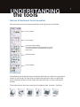
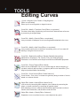
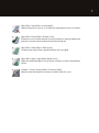
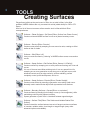
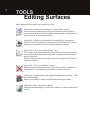
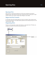
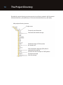
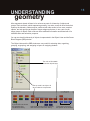
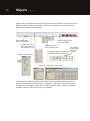
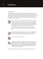
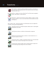
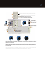
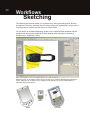
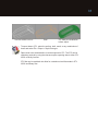
Autodesk Alias 2011
Transition Guide for
Users of Rhino Software
March 2010
2
Copyright and trademarks
© 2010 Autodesk, Inc. All Rights Reserved. Except as otherwise permitted by Autodesk, Inc., this publication, or parts thereof, may
not be reproduced in any form, by any method, for any purpose.
Certain materials included in this publication are reprinted with the permission of the copyright holder.
Trademarks
The following are registered trademarks or trademarks of Autodesk, Inc., and/or its subsidiaries and/or affiliates in the USA and
other countries:
3DEC (design/logo), 3December, 3December.com, 3ds Max, Algor, Alias, Alias (swirl design/logo), AliasStudio, Alias|Wavefront
(design/logo), ATC, AUGI, AutoCAD, AutoCAD Learning Assistance, AutoCAD LT, AutoCAD Simulator, AutoCAD SQL Extension,
AutoCAD SQL Interface, Autodesk, Autodesk Envision, Autodesk Intent, Autodesk Inventor, Autodesk Map, Autodesk MapGuide,
Autodesk Streamline, AutoLISP, AutoSnap, AutoSketch, AutoTrack, Backburner, Backdraft, Built with ObjectARX (logo), Burn,
Buzzsaw, CAiCE, Civil 3D, Cleaner, Cleaner Central, ClearScale, Colour Warper, Combustion, Communication Specification,
Constructware, Content Explorer, Dancing Baby (image), DesignCenter, Design Doctor, Designer’s Toolkit, DesignKids, DesignProf,
DesignServer, DesignStudio, Design Web Format, Discreet, DWF, DWG, DWG (logo), DWG Extreme, DWG TrueConvert, DWG
TrueView, DXF, Ecotect, Exposure, Extending the Design Team, Face Robot, FBX, Fempro, Fire, Flame, Flare, Flint, FMDesktop,
Freewheel, GDX Driver, Green Building Studio, Heads-up Design, Heidi, HumanIK, IDEA Server, i-drop, ImageModeler, iMOUT,
Incinerator, Inferno, Inventor, Inventor LT, Kaydara, Kaydara (design/logo), Kynapse, Kynogon, LandXplorer, Lustre, MatchMover,
Maya, Mechanical Desktop, Moldflow, Moonbox, MotionBuilder, Movimento, MPA, MPA (design/logo), Moldflow Plastics Advisers,
MPI, Moldflow Plastics Insight, MPX, MPX (design/logo), Moldflow Plastics Xpert, Mudbox, Multi-Master Editing, Navisworks,
ObjectARX, ObjectDBX, Open Reality, Opticore, Opticore Opus, Pipeplus, PolarSnap, PortfolioWall, Powered with Autodesk
Technology, Productstream, ProjectPoint, ProMaterials, RasterDWG, RealDWG, Real-time Roto, Recognize, Render Queue,
Retimer,Reveal, Revit, Showcase, ShowMotion, SketchBook, Smoke, Softimage, Softimage|XSI (design/logo), Sparks,
SteeringWheels, Stitcher, Stone, StudioTools, ToolClip, Topobase, Toxik, TrustedDWG, ViewCube, Visual, Visual LISP, Volo, Vtour,
Wire, Wiretap, WiretapCentral, XSI, and XSI (design/logo).
All other brand names, product names or trademarks belong to their respective holders.
Disclaimer
THIS PUBLICATION AND THE INFORMATION CONTAINED HEREIN IS MADE AVAILABLE BY AUTODESK, INC. “AS IS.”
AUTODESK, INC. DISCLAIMS ALL WARRANTIES, EITHER EXPRESS OR IMPLIED, INCLUDING BUT NOT LIMITED TO ANY
IMPLIED WARRANTIES OF MERCHANTABILITY OR FITNESS FOR A PARTICULAR PURPOSE REGARDING THESE
MATERIALS.
Published by:
Autodesk, Inc.
111 McInnis Parkway
San Rafael, CA 94903, USA
Contents
Autodesk Alias 2011
Transition Guide for users of Rhino software
Resources ii
Understanding the tools 1
Curves 2
Editing surves 4
Creating surfaces 6
Editing surfaces 8
Evaluating surfaces 10
Understanding data management 12
The project directory 14
Understanding geometries 15
selections and transforms 17
duplicating 21
geometry display 22
construction history 24
Construction options 25
Workflows: Visualizing 26
Sketching 28
Animating 29
Exporting to CAD and STL 30
3
Resources
To familiarize yourself with Alias, we recommend you read the Getting Started guide
(provided as a booklet and available as a PDF file at http://aliasdesign.autodesk.com), and
watch the seven one-minute Learning Movies (available from Help > Learning Movies)
before reading this guide.
The Learning Alias Tutorials teach you some of the Alias philosophies, so it is worth while
for you to review these tutorials. The front of the book provides additional information about
resources to get help and learn more about Alias.
The Online Documentation (Help > Alias Help) is also a great source of information which
is worth getting familiar with. It is linked up with the Alias product to provide you with
context-sensitive information about tool and menu options.
The Autodesk community website provides great information to get up to speed: go to
http://aliasdesign.autodesk.com/. Bronze membership is free.
UNDERSTANDING
the tools
Curves & Surfaces Tools Location
Alias curves and surfaces creation and editing tools are all located in the Palette:
Curve creation
Curve editing
Curve and surface editing
This area contains all the tools that work on both
curves and surfaces, and sometimes, groups of
these items.
Surface creation
Surface editing
Primitives
Alias primitives can be placed using a manipulator while they are created or by typing their
location in the Prompt Line. After they are created, Alias primitives can be re-positioned
and re-scaled via the Move, Rotate, Scale and Nonp-Scale tools, or via the Information
Window.
The surface primitive tools are located in the tool palette under Surfaces > Primitives:
Sphere
Torus
Cylinder
Cone
Cube
Plane
1
2
TOOLS
Curves
Alias has three types of curves: NURBS Curves, Blend Curves, and Keypoint Curves.
NURBS - this is the most used curve type in Alias. It is
also described as a freeform curve.
NURBS curves can be drawn by placing Control
Vertices (CVs) or Edit Points (EPs) or by drawing them
freehand (Curves > New Curve > New Sketch Curve).
Blend Curve – is a NURBS Curve with special
constraint points (blend points) that provide different
manipulation tools for curve placement, and alignment
with construction history. These curves display in green
by default with crosshair anchor points.
Blend Curves have their own toolbox.
Blend Points can either be edited through the Blend
Tools toolbox or with Pick > Point Types > Blend Point
and Transform tools
Keypoint Curve – is a NURBS Curve with special
constraints to generate CAD-like lines and arcs. These
curves display in blue by default with square anchor
points.
Keypoint curves have their own toolbox.
The extra CAD-like information is accessible in the
Information Window.
Keypoints can only be moved interactively using the
Drag Keypoints tool in Curves > Keypoint Curve
Toolbox.
3
The simpler the curve, the better. Curves are the foundation of surface creation. Poor
quality curves result in poor quality surfaces.
Do not hesitate to rebuild curves to clean or simplify them as you work, especially if the
curves have been edited by inserting points, connecting curves, etc.
Curves > New Curves > New CV Curve [Rhino: Curve]
Creates new NURBS curves by placing CVs. Curves of degree 1, 2, 3, 5 or 7
can be generated. The default is 3. By default the curve starts displaying after
the minimum number of CVs based on the curve degree are set. To see the
curve build as CVs are laid down, select the Progressive Degree option.
Curves > New Curves > New Edit Point Curve [Rhino: InterpCrv]
Creates new NURBS curves in the scene by placing edit points. Curves of
degree 1, 2, 3, 5 or 7 can be generated. The default is 3.
Curves > Primitives > Circle [Rhino: Circle]
Creates a NURBS curve in the form of a planar circle.
The circle diameter is driven by the object’s scale.
Curves > Keypoint Curve Toolbox > Circular Arc [Rhino: Circle]
Creates basic shape using keypoint curves. This tool enables you to specify a
circle by first placing its centerpoint, and then clicking to indicate a point that
lies on the curve. The circle’s radius can then be edited in the Information
Window.
Curves > Keypoint Curve Toolbox > Lines > Line
Allows you to create a single keypoint line. The line’s length can then be edited
in the Information Window.
4
TOOLS
Editing Curves
Curves > Keypoint Curve Toolbox > Drag Keypoints
[Rhino: no equivalent]
Allows you to move keypoints on keypoint curves.
Curve Edit > Modify > Transform Curve [Rhino: no equivalent]
Provides a direct way of positioning a curve so that it intersects two rail curves
by conserving its original shape.
Curve Edit > Modify > Stretch [Rhino: no equivalent]
Lets you stretch or reshape a curve by moving handles attached to the curve.
Curve Edit > Modify > Add Points [Rhino: no equivalent]
Lets you add control points to the end of an existing curve, as if you were still
drawing it using the new curve tools.
Curve Edit > Rebuild Curve [Rhino: Rebuild, RebuildCrvNonUniform,
MakeUniform, SimplifyCrv, Fair, Smooth, FitCrv and ChangeDegree]
Recreates a curve with the same shape but different mathematical properties.
Curve Edit > Project Tangent [Rhino: Match]
Allows for the modification of a curve or surface edge to achieve tangency or
curvature continuity with a surface, or tangency with a curve intersection. [The
Align tool provides similar functionality.]
Curve Edit > Curve Section [Rhino: Delete Subcurve]
Curve Section - Cuts, trims, or creates new geometry along a number of curves
based on a chosen criterion.
Object Edit > Attach > Attach [Rhino: Match Curve]
Joins curves by connecting their endpoints, joins surfaces by connecting the
edges, or closes a surface by connecting its opposite edges.
Note: attaching curves or surfaces with coincident edges can lead to nodes or
tension at the intersection, and should be used with care.
Object Edit > Attach > Detach [Rhino: Subcurve]
Separates a curve or surface into two or more objects at any point.
5
Object Edit > Insert [Rhino: no equivalent]
Adds an edit point to a curve, or an edit point isoparametric curve to a surface.
Object Edit > Extend [Rhino: Extend Curve]
Extends a curve or surface beyond its current endpoint or edge by adding new
geometry. A precise value can be entered at the prompt line.
Object Edit > Offset [Rhino: Offset Curve]
Creates a new object offset a specific distance from an original.
Object Edit > Align > Align [Rhino: Match Curve]
Aligns the endpoints/edges of curves and/or surfaces, or interior isoparametric
curves.
Locators > Curve Curvature [Rhino: Curvature Graph]
Adds a locator that shows the curvature or radius comb of a curve.
6
TOOLS
Creating Surfaces
Polysurfaces (solids) as they are known in Rhino, do not exist in Alias. In the Alias
workflow, NURBS surfaces are only converted into solids (called shells) for CAD or STL
Export.
Here is a list of the most common surface creation tools in Alias with their Rhino
correspondences:
Surfaces > Planar Surfaces > Set Planar [Rhino: Surface from Planar Curves]
Creates a trimmed NURBS surface from a set of planar boundary curves.
Surfaces > Revolve [Rhino: Revolve]
Creates a new surface by sweeping a curve around an axis, creating an effect
similar to that of a lathe.
Surfaces > Skin [Rhino: Loft]
Lets you create a surface by “skinning” a NURBS surface across cross-section
curves.
Surfaces > Swept Surface > Rail Surface [Rhino: Sweep 1 & 2 Rail(s)]
Creates a surface by sweeping one or more profile curves along one or two rail
curves.
It is one of the most used Alias surfacing tools. It is a very powerful tool for
sweeping one or more generation curves along one or two path curves, with
advanced controls such as edge continuity, surface rebuilding, surface
complexity control, profile development, and so on.
Surfaces > Swept Surfaces > Extrude [Rhino: Extrude Straight]
Creates a new surface by extruding a generation curve along a path curve.
Normally used to make tubular objects with symmetrical cross sections.
Surfaces > Boundary Surfaces > Square [Rhino: no equivalent]
Create surfaces by blending four boundary curves (or curve segments), while
maintaining continuity with adjacent surfaces.
Square generates a “patch” that is “stretched” between opposite edges.
Surfaces > Surface Fillet [Rhino: Fillet Surface and Variable Radius Fillet
Surface]
Creates a transition surface between two sets of tangent continuous surfaces
of constant, variable, radius, chord length or tangent length (many other
advanced options are available).
7
Surfaces > Round [Rhino: Fillet Edge and Variable Radius Fillet Surface]
Creates constant or variable rounded surfaces along any number of pairs of
edges, with different corner handling options. Initial surfaces must intersect
before using Round.
Surfaces > Multi-Surface Blend > Freeform Blend [Rhino: Blend Surface]
Creates a transitional surface based on two input contact lines.
Surfaces > Multi-Surface Blend > Profile Blend [Rhino: no equivalent]
Creates one or many transitional surface(s) between multiple continuous
surface boundaries, by specifying any number of cross-sections (profile curves)
between the primary surfaces.
This tool is similar to Freeform Blend but allows the selection of one or more
profile curves to control the transitions.
Surfaces > Draft Surfaces > Draft/Flange [Rhino: ExtrudeCrvTaper]
Creates ruled surfaces by pulling a surface from a curve or surface
curve in a given direction, or by pulling a surface curve at an angle
to the surface normal. This tool generates draft surfaces from
curves or surfaces edges with a given angle based on the XYZ axis
or a given vector; or flange surfaces from surface edges based on
the surface normal.
Surfaces > Rolled Edge > Tubular Offset [Rhino: no equivalent]
Create a tube and intersect the tube with input surfaces to generate offset
curves.
Generates tubular surfaces from Curves On Surfaces, isoparms, or surface
edges. This is very useful to mark parting lines in visual models.
Surfaces > Curve Network [Rhino: NetworkSrf]
Curve networks let you build surfaces very quickly from a network of
intersecting curves.
Builds a network of surfaces from a network of curves. This is good for building
quick conceptual models, or models that can be refined later if needed.
Surfaces > Tube Surface [Rhino: Pipe]
Creates a tube using free curves as a path. These tube surfaces can have a
variable radius.
No Alias equivalent [Rhino: Patch]
8
TOOLS
Editing Surfaces
After building primary surfaces, the next task is to refine.
Surface Edit > Create CurvesOnSurface > Project [Rhino: Project]
Create curves-on-surface from existing curves and surfaces by projecting
curves onto surfaces based on the modeling view selected, an axis direction, a
projection vector, or the surface normals.
Surface Edit > Create CurvesOnSurface > Intersect [Rhino: Intersection]
Creates a Curve-on-surface at the intersection of two surfaces. The curve-onsurface can be generated on the first surface selected, or on both.
Surface Edit > Trim > Trim Surface [Rhino: Trim]
Trims or splits surfaces based on the position of the trim locator which can be
used to define either the discard or kept surface. Clicking Divide keeps both
parts of the surface.
Multiple surfaces can be trimmed while in the tool by using the SHIFT key to
select new surfaces.
Surface Edit > Trim > Untrim [Rhino: Untrim]
Restores the trimmed part of a surface. There are two options: undo the last
trim operation, or undo all trims on a surface or a group of surfaces.
Surface Edit > Rebuild Surface [Rhino: Rebuild, MakeUniform, Smooth, FitSrf
and ChangeDegree]
Allows you to simplify or modify a surface while preserving its shape.
Object Edit > Align > Align [Rhino: Match]
Aligns the endpoints/edges of curves and/or surfaces, or interior isoparametric
curves.
9
Object Edit > Attach > Detach [Rhino:Split]
Separates a curve or surface into two or more objects at any point.
Object Edit > Insert [Rhino: no equivalent]
Adds an edit point to a curve, or an isoparametric curve to a surface.
Use to gain control over the shape definition of a surface. This is especially
useful in Direct Modeling. Insert displays the new CV distribution to help place
new isoparms interactively (CVs/hulls must be turned on to use this feature).
Object Edit > Extend [Rhino: ExtendSrf]
Extends a curve or surface beyond its current endpoint or edge by adding new
geometry.
A precise extend value can be entered in the Prompt Line.
Surfaces can be extended, or generate a new surface from the original surface
edge. Trimmed surfaces need to be un-trimmed before Extend can work.
Surface Edit > Stitch > Shell Stitch [Rhino: Join & CreateSolid are similar tools]
Creates a special object called a shell from a group of surfaces, in preparation
for export to a CAD package or STL (see Export to CAD & STL). To avoid any
data loss or deformation, work with the original data in Alias; save the file, and
in a new copy, stitch the data required for CAD or STL export.
Surface Edit > Stitch > Shell Unstitch [Rhino: Explode (similar)]
Converts a shell object back to normal surfaces.
Stitching and unstitching Alias data de-natures the original NURBS data. To
avoid any data loss or deformation, always work with the original NURBS data
in Alias, and use the stitched models (shells) for CAD or STL export only.
10
Tools
Evaluating surfaces
Alias offers very powerful visual aid tools to evaluate surface quality or surface continuity
that can be used while in the modeling tools (for example, while in a tool such as Rail,
Continuity Check can be toggled on/off).
Surface Continuity Evaluation
(Evaluate > Continuity > Surface
Continuity)
Checks the positional, tangent plane,
and curvature continuity between and
inside surfaces.
If the tool is set to curvature:curvature
continuous edges are displayed in
green with a C symbol;
noncurvature continuous but tangent
continuous edges display in red with
a C symbol,
non-tangent continuous but position
continuous edges display in red with
a T symbol,
and non-positional continuous edges
display in red with a P symbol.
Diagnostic Shade
The different tools for visual
evaluation are conveniently
placed in the Control Panel
or Object Display >
Diagnostic Shading. The
options for the selected tool
are displayed below the
tools by expanding the
white arrow. The quality of
the shading can be refined
via the tolerance parameter.
tessellation quality
diagnostic shading tools
tool options
11
These diagnostic shading tools can be selected in the Control Panel or by choosing Object
Display > Diagnostic Shading.
Multi Color
Each surface can have its own color
defined. A Reflection option increases its
usefulness for evaluation purposes.
Random color
Assigns random colors temporarily. Helps evaluate patch layout of
a model.
Horizontal/vertical stripes
Displays zebra stripes that help evaluate surface highlights
and transitions
Draft angle evaluation
Helps evaluate models for molding purposes. Requires that
surface normals be set correctly to provide useful results.
Shade-sky
Also Double-Horizon or User-Defined
texture. Assign reflective maps to evaluate
highlights and flaws.
Hidden line display
Although not strictly an evaluation tool,
Window Display > Hidden Line is a usefufl
modeling and evaluation aid.
Iso-angle
This lets you visually evaluate continuity across surface boundaries.
You can also use this tool to create iso-angle curves-on-surface.
(not available in all products)
Curvature evaluation
Shows a map that relates the curvature to a color. You can scale
the radius ramp to show finer details of curvature variation.
not available in all products)
12
UNDERSTANDING
Data management
Unlike with Rhino, you can open multiple files in a single Alias session. When multiple files
are opened, they are referred to as Stages. Stages are useful to copy or compare data
between different files.
When creating a file, Alias usually asks whether to delete or not the previously opened or
created file(s). Answering Yes deletes the previously opened or created file(s) and creates
a unique file in the session. Answering No keeps the previously opened or created files and
creates a New Stage.
To switch between stages, select the stage name in the pull-down menu or change the
Working Level in the Stage Editor.
To switch between stages AND change the Modeling Window Source, hide other stages,
press the Ctrl key when selecting the stage name in the pull-down menu or Stage Editor.
Saving Files
The first time you save a file, File > Save opens a dialog asking for a file name. On
subsequent occurrences of File > Save, that file is overwritten. To not overwrite a file, or to
save a file under a new name, use File > Save As.
Files should always be saved in Alias Wire format to save all the Alias features. Saving
(File > Save) or exporting active geometry (File > Export > Active As) in other formats which is required for data transfer for instance –only saves the features supported for the
selected format.
Supported file formats can be selected in the File > Save As and File > Export > Active As
option dialogs. Each format has its own set of options.
Opening files
Opening Files
Alias can open or import many different type of files such as Alias Wire and industry
standard formats. Some file formats offer some options that can be set during File > Open
or Import. See the File > Open or Import option dialogs for more details.
Supported File Formats
For information about file formats supported for import and export in Alias, please refer to
the online documentation in the Data Transfer manual and in the Reference section for File
> Open and File > Save.
Organizing Data
To keep your data organized, create a New Project on a per project basis. This helps you
manage your projects with all the files associated with them.
13
14
The Project Directory
By default the project directory structure required to run Alias is created in My Documents\
Autodesk\Alias\user_data (Windows) or Documents/Autodesk/Alias/user_data (Mac).
Alias projects directory structure
Project name
Frequently used directories
Canvases and sketches storage
Rendered images, QTVRs and the
like stored here
Scene description language (SDL) files for
command line rendering
STL and SLC files for export to CAD systems
File textures storage
Wire files storage
15
UNDERSTANDING
geometry
Alias represents almost all items in its universe as parts of a hierarchy of objects and
groups. Each end block, which represents geometry, is a node, as are all other blocks that
make up the hierarchy. Nodes may be combined with other nodes to form more complex
objects, and sub-groups can be part of larger subgroups that are, in turn, part of even
larger groups of objects. Each node can have additional information associated with it for
transformation and animation purposes.
You can see how this hierarchy of objects is represented in the Object Lister and the Scene
Block Diagram (SBD) window.
The Object Lister and the SBD window are very useful for selecting data, organizing,
grouping, ungrouping, and assigning to layers or assigning shaders.
The color of this swatch
shows the object’s layer.
The top node is an object. All
other nodes are components.
A green leaf node shows
the geometry has
construction history.
A blue leaf node shows the geometry
does not have construction history
These three leaf nodes
are specific to the camera.
16
Objects continued
Objects can be organized by layers to help you work more efficiently. Layers can be set to
Reference (data is visible but grayed out, and can be snapped to) or Inactive (data is
grayed out but cannot be snapped to).
Active Construction
Layer is highlighted
Invisible layer. Click
layer color swatch to
turn visibility on or off.
Windows > Object lister
Click and hold to open
layer color palette
Click layer name to
open pull-down menu
Drag middle
mouse button
on layer to
To organize layers in the layer bar move it.
(for example, moving layer L4)
Windows > Information > Layer stats
Layer Symmetry enables display of the second half of symmetric models you build. To
change the symmetric plane use Layers > Symmetry > Set Plane. To turn the symmetry
into geometry, use Layers > Symmetry > Create Geometry. This is useful for creating a
complete model for CAD or STL export, for example.
UNDERSTANDING
17
selections and transforms
The way you select and transform items in Alias is different from Rhino. Although the
Transform tools (Move, Rotate, Scale and Nonp-Scale) are common to all entity types
(Objects, Object Components such as Curves, Surfaces, CVs, Edit Points, Templates, and
so on), each type has its own selection, or pick tool.
The process of applying transforms to the different entity types is to enter the selection
mode first. So to move control vertices (similar to Rhino’s Control Points), choose Pick >
Point Types > CV and then Transform > Move. The CV selection can be made before
selecting the Move tool, or edited after by pressing the Shift key, which temporarily
suspends the transform tool.
In any selection or transform mode, picking an object or component with the left mouse
button adds or removes objects from the selection. The right mouse button removes
objects from the selection. The middle mouse button starts a new selection. [Tip: While in a
selection mode, pressing the middle mouse button in empty space makes sure nothing at
all is picked: it’s like using the Pick > Nothing tool]. These three picking modes can be
assigned to any of the mouse buttons through Preferences > Selection Options.
Grouping
Grouping and ungrouping is an important part of the Alias workflow. While surfaces may be
joined in Rhino to create polysurfaces that act like solids, in Alias, you work with NURBS
surfaces to ensure the integrity of the data during the entire modeling process. It is why
you might find yourself grouping and ungrouping surfaces into objects in Alias rather than
joining and exploding in Rhino. The only time objects are turned into solids in Alias is to
generate data for CAD or STL export. Solids in Alias are called shells, and are created
using the Surface Edit > Stitch > Shell Stitch tool. (see Export CAD & STL Data at the end
of this booklet).
Edit > Group
Groups the picked objects into a single object, allowing you to pick and apply
transformations to all the components at once.
Edit > Ungroup
Separates the components of a group into individually pickable objects.
18
Transforms continued
Transforms
Transforms in Alias differ from Rhino because the transforms are applied to the group of
objects, objects, or object components (like surfaces, CVs, and such) based on their
position in space and the position of their pivot point. The transform tools do not require the
origin of the transforms to be set like in Rhino. When needed, the Pivot Point can be
moved first to accommodate the desired transforms. Transform tools are located on the
“Transform” tab on the tool palette.
Move – moves objects in XYZ with the aid of the mouse. In the Perspective
window, the left mouse button constrains movement to the X dimension, the
middle mouse button to Y, and the right mouse button to Z. In Orthographic
windows, the left mouse button moves freely on the orthographic plane, the
middle mouse button constrains movement horizontally, and the right mouse
button constrains movement to the vertical direction. XYZ location.
The default Perspective View transform constrains can be changed in
Preferences > General Preferences Input: Mouse Mapping For Perspective
Move.
Rotate – rotates objects in XYZ with the aid of the mouse. In all windows, the
left mouse button constrains rotations about the X axis, the middle mouse
button about the Y axis, and the right mouse button about the Z axis.
Scale – scales objects uniformly in XYZ.
Nonp-Scale – scales object non-proportionally in XYZ. In the Perspective
window, the left mouse button constrains operations to the X dimension, the
middle mouse button to Y, and the right mouse button to Z. In Orthographic
windows, the left mouse button moves freely on the orthographic plane, the
middle mouse button constrains scaling horizontally, and the right mouse
button constrains scaling vertically.
The Move and Rotate tools have an option to set their transform axis local or global.
Transforms continued
Transform values can be edited in the Information Window (Windows > Information >
Information Window):
Transform values can also be entered at the Prompt Line:
At the Prompt Line, values are entered in the form X Y Z for the Move, Rotate, and
Nonp-Scale tools. The Scale prompt only allows one value to be set.
The Prompt Line also allows for Absolute (ABS) or Relative (REL) values. To switch
between ABS and REL, type an A or R in the prompt, either by itself, or with the values (for
example, R2 0 1 sets relative values, and moves an object two units in the positive X
direction from where it currently is, keeps the same relative position on the Y axis, and
moves one unit in the positive Z direction).
Pivot Point – Pivot Points are an important component of Alias workflow. They can be
placed appropriately to accommodate the desired transforms. Each node has its own Pivot
Point. Sometimes nodes or groups of nodes are grouped to offer different transforms, or
multi-level transforms.
The way these objects scale depends on the position of their pivot points.
19
20
Transforms continued
Zero Transform – Applies any scaling, translation (movement), and rotation to
the picked objects at the geometry level, so the transform values on the object
nodes are reset to zero.
Set Pivot – enables you to move a Pivot Point. Pivot Points can be snapped to
the grid, other objects, or object elements.
Center Pivot - centers the Pivot Point of a group of objects, an object, or object
components based on a cubic volume that contains all the selected items (their
bounding box).
Other Transform Tools – Alias also provides a set of Deformation tools in the Object Edit
tool palette, under Dynamic Shape Modeling.
Lattice Rig: provides a box-shaped manipulator called a lattice to enable global
modifications to the model.
Twist Rig: twist a surface or collection of surfaces about a single axis.
Bend Rig: bend selected geometry to conform to a user-created curve; or a
continuous sequence of curves.
Conform Rig: deform or “badge” an otherwise flat feature onto a curved surface
so that the output conforms to the shape of the curved surface.
Transformer Rig: transform shapes made of multiple surfaces to explore and
communicate large shape changes with custom modifiers.
UNDERSTANDING
duplicating
Duplicate Object – The Duplicate tools in Alias offer similar functionality to the Array tools in
Rhino. Again, pivot point placement and grouping help provide the desired results.
Edit > Duplicate > Object [Rhino: Array]
Choose from the Edit menu to make copies of existing objects.
Edit > Duplicate > Mirror [Rhino: Mirror]
mirrors object based on the XY, YZ, or ZX planes selected via the option box.
Transform > Object Placement > Duplicate Place Toolbox
[Rhino: no equivalent tool]
This tool takes an input set of targets and automatically duplicates and places
the copies along curves (free curves, curves on surface, isoparms, trim edges
and patch precision curves), continuous sequences of curves, or locator points
(currently restricted to locator points on surfaces). The tool also enables you to
specify how these copies are positioned along the selected curves and points.
Snapping
Alias offers similar snapping tools to those found in Rhino
press:
Ctrl (Windows), Control (Mac)
or
Alt (Windows), Command (Mac) or
or
Ctrl + Alt (Windows),
Control + Command (Mac)
to snap to:
CVs,Edit points, Keypoints, or Blend points
Grid
Curve, Surface, edge, or Isoparm
opens Snap Options
21
22
UNDERSTANDING
geometry display
Display
While modeling, the way models are displayed is important. Alias offers many choices.
Control the display within a
modeling window through
its embedded Show menu.
The same controls are
available by choosing
WindowDisplay > Show or
one of the WindowDisplay
> Toggles menu items.
Press the Shift key to
toggle more than one item
at a time. Select All
Windows to apply the
settings to all windows.
(This is the default.)
The Control Panel offers
display controls on a per
curve or surface basis.
These controls are also
available by choosing
Object Display > Control.
The display of new curves
and surfaces can also be
set in the Display Control
window.
Geometry display
continued
You can adjust the visibility of individual objects or groups of
objects using Object Display > Invisible, Toggle Visibility, or
Hide Unselected.
All objects can be redisplayed by choosing Object Display >
Visible. To re-display only some objects, change the Object
Display > Visible option All to Pick before picking the objects in
the Object Lister or the SBD Window.
Objects can also be
shaded through the
diagnostic Shading tools
located in the Control
Panel or Object Display
> Diagnostic Shading.
The diagnostic Shading
tools apply to the
selected objects if any,
or to all the visible
objects when none are
selected.
Hardware Shade and
Diagnostic Shade are
independent tools that
do not share their color
information.
Orthographic windows can be
synchronized with WindowDisplay >
Window Sync. This is very useful for
keeping the proportions of the
orthographic modeling windows
proportional. (This is the default.)
Hardware Shade or Hidden Line display
can also be switched on via the Window
Display menu.
23
24
UNDERSTANDING
construction history
Alias offers solid Construction History support. There are two areas of Construction History
to understand in Alias.
Geometric dependency and association. If a curve upon which a surface is based is
modified, the surface is modified. the surface updates interactively when the Preferences >
Performance Options > Construction History Updates During Transform option is set ON.
Moving the
CVs on the
original
curve
updates the
revolved
surface.
Tool options and parameters. Some tools offer options that are editable after the object
is created, either with locators, or by changing information in an option window.
Query Edit the Surface
Fillet.
The Surface Fillet option
window reopens.
Turn on the Variable Fillets
option. Add a radius
locator and size it. Click
Recalc.
25
Construction options
(called “Tolerances” in Rhino)
Set the appropriate construction options (Preferences > Construction Options) to ensure
the quality of your models reflects your construction criteria. Construction options change,
depending on the CAD application the data will be sent to downstream (if any). The presets
available are good starting points. You can duplicate and customize the settings for your
specific needs.
Construction options only apply to surfaces created after the construction options are set.
Changing construction options in a file with existing geometry won’t re-generate the
existing geometry to fit the new construction options; it only affects new surfaces. Old
surfaces that need to fit the new construction options may need to be rebuilt.
presets
custom presets
units
tolerances
26
Workflows
Visualizing
Alias offers high quality hardware and software rendering. Both rendering methods share a
material system.
Hardware Shade mode can be used for real-time model evaluation, live visual
presentations, or snapshots for presentations.
Hardware Shade provides fast visual feedback (real time or close to real time results
depending on model size, functionality selected, etc.) and supports advanced technologies
such as Anti-Aliasing, Bump and Specular Mapping, Cube Map and Environment
Reflections, Ground Plane Shadows, Reflections, Ambient Occlusion, and Image Based
Lighting.
File > Export > Current Window enables you to save Hardware Shade images. For live
presentations, hide the Alias interface using Layouts > Full Screen; use Bookmarks
(Windows > Bookmark Lister) to move between previously defined views.
Hardware Shade can be chosen from the Window Display menu. The Render menu holds
all the other render menus (software renderers, the material manager, and so on).
Software Render offers raycasting and raytracing technologies. Raytracing technology
provides more realistic results because of advanced features such as refraction, object
reflections, and soft shadows. Both software render raycasting and raytracing technologies
support and share Hardware Shade, Ambient Occlusion, and Image Based Lighting (IBL is
not available in all products).
The Multi-lister offers tools to manage lights, materials, and the environment. It provides
you with the ability to set colors, textures, lighting effects like glows, and use image-based
lighting for reflections in your scene.
The materials library available in the Visualize Control Panel is a good starting point to
understand or construct materials. More materials are available at the Autodesk Design
Community website.
You can choose and assign materials using either the Multi-lister or the Control Panel.
27
These two menu items render pictures of the scene.
Default lights are automatically created when
Hardware Shade is turned ON.
You can create other types of lights.
Double-click a
shader in the
library to bring it
into your scene.
Select a
shader
Select a shader
Assign a shader
Select
Shading > Assign to
assign the shader
Create a
new shader
Hardware shade
Hardware shade with
ambient occlusion
Software render with
ambient occlusion
All shader parameters can be edited in the Multi-lister; the most common parameters can also be
edited in the Control Panel.
Double-click a shader in either the Multi-lister or the Control Panel to open the shader editor
window. Single-click a shader in the Control Panel to display the common shading parameters in
the Control Panel.
Image quality (tessellation, anti-aliasing), image file format and resolution (for batch render), and
other parameters, are all set in the Render Globals window (Render > Globals).
28
Workflows
Sketching
The sketching environment allows you to sketch freely with high-quality pencils, brushes
and markers. Geometry elements (curves, surface edges and isoparametric curves) can be
used as guides to generate precise lines or to create masks.
You can sketch in the default application mode, but the optimized Paint workflow reduces
screen clutter and provides a special 2D Paint window used especially for sketching
(Preferences > Workflows > Paint).
Sketching tools can be used to make notes to yourself, or to communicate with team members or
clients. Sketches can be drawn over or mapped to 3D geometry for quickly adding details, or
evaluating design alternatives.
Sketch
Model
Concept
29
Workflows
Animating
Alias offers animation tools to present products in the form of movie files. These can go
from turntable presentations, to more advanced functional presentation, exploded view,
camera flies, etc.
All Alias animation tools are located under the Animation menu.
One commonly used type of animation is called keyframe animation. Object transforms are
set at a certain point in time and recorded, then at another, etc. and the application
interpolates between the transforms to build the animation.
Before animating, display the Time Slider (Animation > Show > Toggle Time Slider):
This example shows the basic principles of keyframe animation to open a box.
The box is a
cube primitive.
Pick the top
surface (it’s a
component of
the cube).
Move the pivot Set a keyframe
point to the
at frame 0.
rotation axis to
make a hinge.
Move the
current frame
to 30 on the
time slider.
Rotate the lid.
Set a keyframe
at frame 30.
The lid has now
been animated.
The animation
can be played
back by
scrubbing or
clicking the
playback button
in the time
slider.
Real-time turntable animations can be created using Animation > Turntable.
QuickTime VR files can be created using Render > Render to QuickTime VR: create
walk-around scenes, rotisserie, or turntable mode files by setting a few options. Alias gives
you the ability to output movies in many different formats.
For more information on animating in Alias, go to the online Help section, Animating > How
do I?.
30
Workflows
Exporting to CAD & STL
CAD - it is usually recommended to stitch data before exporting it to CAD (this may vary,
depending on the target CAD application or the file format chosen).
In this process, stitch the data to generate a shell. Then with only the shells selected,
choose File > Export > Active As. The option dialog enables you to select different file
formats and appropriate setting options that are based on the selected format.
Surface Edit > Stitch > Shell Stitch
Creates a special object called a shell from a group of surfaces, in preparation
for export to a CAD package or STL.
Gaps in a shell are highlighted in yellow (or in pink when the shell is not
selected). These gaps are usually the result of gaps in the original NURBS
model. User-defined stitching tolerance can be set by unmarking the Use
Construction Options in the Stitch tool to try coping with these gaps.
Sometimes the NURBS geometry itself will need to be fixed.
Evaluate > Check Model
Checks all, visible, or picked objects for common problems that may prevent
data transfer.
It is useful to check the data before shelling or exporting via Check Model. The
tool can identify short edges, multiple knots, internal tangent discontinuities,
and so on. It includes check boxes for G0, G1 and G2 continuity.
Selected NURBS model
Shell
31
Selected NURBS surfaces
Shell
STL data pre-visualization
before export
To export data to STL, select the surface, shell, mesh, or any combination of
these and select File > Export > Rapid Prototype.
Data needs to be stitched before it can be exported to STL. The STL can be
refined as required by using the tolerance option exporting data to either STL
ASCII or Binary formats.
STL files can be read back into Alias for evaluation since Alias reads in STL
ASCII and Binary files.