1
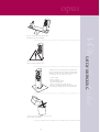
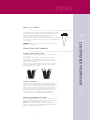
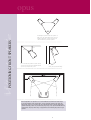
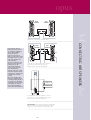
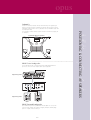
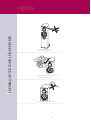
opus
USER MANUAL
Opus 1
Opus 2
Opus 3
Tri-centre
Tri-surround
opus
CONTENTS
User Warnings
Quick Start Guide
About Your Loudspeaker
Specifications
Quality Assurance
WITHIN THIS PACK
Certificate of Quality Assurance
Systems and Driver Unit Test Reports
4 x White Cotton Gloves
Accessories
2
opus
USER WARNINGS
Please read the following notes carefully. They will help you to install your loudspeakers correctly and safely.
Switch off the amplifier and all sources before making connections to your sound system. When you switch on
the system or change sources, set the volume control to minimum and turn up the level gradually.
The position of your Volume Control is NOT a reliable guide as to the maximum capabilities of your system.
Playing the system with extreme settings of volume and tone controls may damage the amplifier and loudspeakers.
Do not connect loudspeaker terminals to the mains supply.
Ensure that your loudspeakers are correctly wired and are in phase.
Do not subject your loudspeakers to excessive cold, heat or sunlight.
WARNING: To reduce the risk of fire or electrical shock do not expose this product to rain or moisture.
The product must not be exposed to dripping and splashing and no object filled with liquids – such as a vase
of flowers – should be placed on the product.
No naked flame sources – such as candles – must be placed on the product.
Do not place heavy objects on top of loudspeaker cabinets. If you play them with the grilles removed be
careful to protect the drive units from children and pets.
Do not use makeshift stands. Always fit a manufacturer’ approved stand using the instructions and the
fixings provided. Your dealer will advise you.
Do not attempt to dismantle the loudspeaker. There are no user serviceable parts inside and you will
invalidate the warranty.
Site your loudspeaker at least 0.5m away from TV sets and magnetic storage media.
3
opus
QUICK SETUP GUIDE
(Opus Series)
4
opus
Setting Up the Opus Series
Safely unpacking
Check you have
Loudspeaker preparation
Positioning stereo Hi-fi speakers
Connecting stereo Hi-fi speakers
Positioning AV speakers
Connecting AV speakers
Setting up AV systems
Looking after your loudspeakers
5
opus
Your Opus speakers are heavy. Take care when
removing them from their packaging.
Carefully remove each loudspeaker from its packing carton.
Be especially careful when removing the polythene bag. The
speakers come with the plinth complete and already fitted.
The carton top says, “Open other end”. So you,
– Open the bottom
– Remove polystyrene
– Open bag containing speaker
– Tape the carton flaps back
– Turn over carton with loudspeaker still inside
– Lift carton off, leaving loudspeaker standing on the floor
– Be careful not to damage soft floor surfaces with spikes
If possible, keep the packaging in case you need to
move or return your speakers.
6
SAFELY UNPACKING
Always take care when lifting heavy objects.
Lift the speakers out by their sides.
CHECK YOU HAVE
opus
Opus 1, 2, 3
Opus Tri-Centre
User Pack
User Pack
User Pack
Accessories:
Accessories:
Accessories:
•
•
•
•
•
• 2 Gloves
• Rubber Feet
• Bi-wire Links
• 2 Gloves
• Rubber Feet
4 Gloves
Long spike set (4)
Soft floor spike seats
Foam pad (4)
Bi-wire Links (4)
7
Opus Tri-Surround
opus
OPUS 1, 2 & 3 SPIKES
Your floor standing Opus speakers are delivered with the plinth and spikes already
fitted. Levelling/seating the speaker is best achieved by adjusting either of the rear
spikes until the speaker is stable without rocking. Release the top knob, on the
underside. Turn spike out and down to level. Re-lock top knob.
For wood or soft floors 8 metal spike seats and self-adhesive pads are provided for
use as required. A set of extra long spikes for deep carpets are provided and may be
used as required.
CONNECTIONS AND TERMINALS
Choosing and Preparing Cables
Specialist audio cable usually offers better performance than general purpose
‘bell’ or ‘zip’ wire.
Choose a cable of suitable diameter – cable that is too thin will limit the
dynamics of the sound and may impair the bass response. Audio cable is
polarised, with two cores of different colours, or often a raised rib of coloured
tracer in the case of twin cable.
Split the twin cores to a depth of about 40mm. Carefully strip the insulation
from each end, leaving about 10mm of bare wire. If the cable is stranded,
lightly twist to gather any loose strands.
10mm
40mm
Crossover Networks
OPUS front and centre loudspeakers use a specially designed bi-wireable
crossover panel with six terminal binding posts. Please follow the drawing carefully to see the correct orientation of the loudspeaker terminals. The upper terminals connect to the treble unit, the middle pair to the mid-range and the
lower pair to the bass units. As supplied, the treble terminal pair is connected
to the mid-range pair and bass terminal pair via removable metal straps.
These should be left in place for standard single cable installations.
The OPUS surround uses a conventional twin terminal crossover panel.
Connecting Loudspeaker Terminals
Unscrew the terminal. Thread the bored end of each cable through the hole in
the bottom of the terminal post. Ensure that there are no loose strands which
may touch adjacent terminals. Retighten the terminal securely.
NOTE: When connecting loudspeakers, the cables to left and right channels
should be of equal length, regardless of the distance of the speakers from the
amplifier. This applies to front and rear channels.
8
LOUDSPEAKER PREPARATION
WARNING: Opus speakers are heavy and the spikes can penetrate softer floors
materials over extended periods.
Positioning the speakers. Place the speakers so
that you are the same distance from each. The
distance between the speakers should be the
same as between you and the speakers.
20cm
70cm
0
5º - 3
º
Angle speakers inward by 5º to 30º for a
clearer, more tuneful mid range.
º
For best results the speakers should be at best
10 inches (20cm) in front of a wall and at least
30 inches (70cm) from any corner.
40
POSITIONING FRONT SPEAKERS
opus
15º
-
If the loudspeakers are placed too close to the walls the bass will increase but may be
boomy and indistinct. If the loudspeakers are placed further away from the walls, the
inward angle may be increased by upto 40%, although this may restrict the width of the
optimum listening position. As personal taste plays a large role, experiment with different
configurations and play a wide range of programme before finalising the position of your
speakers.
9
opus
RIGHT
SPEAKER
LEFT
SPEAKER
L.SPKR
R.SPKR
Single wired a single amplifier, tri-link bar is fitted
Using separate cables for
treble, mid and bass units in
Tri or Bi-wiring configuration
reduces intermodulation
effects and improves
headroom and clarity. To
Bi-wire, you will need to install
two lengths of twin core cable
between the amplifier and
each loudspeaker.
Unscrew each terminal a few
turns and remove the metal
tri-link straps. Use the
bi-link straps (supplied in
accessories) to connect the
treble and mid-range
terminals. Connect the cables
between the amplifier and the
loudspeakers as indicated and
re-tighten all the terminals
securely.
Note: Some amplifiers have
two pairs of output terminals
to facilitate bi-wiring but this is
not essential. The advantages
of bi-wiring are fully retained if
your amplifier has only one
pair of output terminals per
channel (as in the illustration).
LEFT
SPEAKER
AMPLIFIER
R.SPKR
L.SPKR
Tri or Bi-wired – a single amplifier, with separate wires
to drive the bass/mid unit and the treble unit.
Additional links are supplied to allow Bi-wiring.
Amp
Amp
Tri or Bi-amplified – two or three amplifiers. One drives
each section or 2 sections with Bi-wire link e.g mid/hf.
(Remove all link sections when Tri-Amping)
Important Note, please make sure that heavy multi-standard
cables are well connected and clamped. Single loose strands
arcing can cause noise in the woofers like a faulty speaker.
10
CONNECTING HIFI SPEAKERS
RIGHT
SPEAKER
opus
THE HOME THEATRE ENVIRONMENT
POSITIONING AV SPEAKERS
Front and Effects Channels
The front loudspeakers are placed on either side of the television screen, 2 to 3 metres apart. The speakers
should be angled slightly so they are aimed towards the listeners.
As the rear surround channels are the ‘effects’ channels the reproduced sound should be as room filling as
possible. We recommend placing the speakers in a high position, behind the listeners head. If the rear wall is
more than 1 metre behind the listening seat, position the units on the side walls. If the walls are a long way
from the listening seat, consider stand mounting the loudspeakers.
Most of the dialogue comes from the centre loudspeaker. Speech should appear to originate from the actors
mouths. Operating height is important. Ideally the front and centre channel speakers should be at the same
height. For this reason the centre channel speaker is best operated above the television monitor.
The OPUS Tri-Centre Loudspeaker
The loudspeaker should be positioned centrally between the loudspeakers close to the television and mounted
either above or below the screen.
The loudspeaker should be located on a stable flat surface to avoid any danger of the cabinet moving when it
is vibrated by high sound levels. If you mount the unit on top of the television, move it forward so that the
front grilles are level with or slightly in front of the screen. This will reduce reflections from the screen and the
top of the cabinet.
Although you can place the centre channel loudspeaker under the TV monitor, this should be regarded as a
second best. The preferred position is always above the monitor.
The OPUS Tri-Surround Loudspeaker
Connect the cable to the speaker. The speaker should ideally be sited 600mm – 1.5 metres above the listening position and 2.5 - 3.5 metres apart, central to the listener and behind the listening position, preferably on
a rear wall. If the listening position is some distance from a rear wall, the loudspeakers may be mounted on
opposite side walls but always behind the listening position.
Ensure that the wall is strong and can support the product. Drill two 5mm holes in the wall 160mm apart and
horizontally aligned. Fix a suitable No 8 round head screw firmly into each hole using appropriate wall plugs.
Leave a stub of 5mm protruding from the wall. Align the holes in the mounting brackets over the screw heads
and carefully lower the unit onto the screws. The speaker can now be securely attached with the spacers resting against the wall. Now connect the speakers to the amplifier before final mounting of the surrounds.
System with Side Mounted Tri Surrounds
System with Rear Mounted Tri Surrounds
11
opus
Subwoofer
System with Subwoofer Speakers
OPUS Centre Loudspeaker
A set of self adhesive pads is provided. Peel off the backing material and fix a
pad close to each corner of the bottom surface of the loudspeaker.
Single wiring shown
SUB
WOOFER
RIGHT
RIGHT
LEFT
REAR
CENTRE
LEFT
FRONT
Single wiring shown
RIGHT
LEFT
OPUS Surround Loudspeaker
Four self adhesive spaces are provided with each unit. Attach one close to each
rear corner of the cabinet. This speaker is designed primarily for wall mounting –
please see separate section for this topic.
12
POSITIONING & CONNECTING AV SPEAKERS
As the ear is unable to detect the direction from which deep bass originates, this
allows you freedom to position a subwoofer according to the level of bass required.
Placing the subwoofer near a corner or particularly close to a wall will boost the bass
but may impair clarity.
The performance of Home Theatre systems can often be enhanced by using a pair
of subwoofers.
SETTING UP AV SYSTEMS
opus
Setting Loudspeaker Sizes
Many digital AV Processors require you to specify the size of speakers in all channels. These are usually
‘Large or small’. For Opus set the front speakers to ‘large’, set the centre to ‘large’ and the surrounds to
small. The subwoofer then will reproduce only the LFE bass signals.
If you are not using a subwoofer: Set the front speakers to set the subwoofer option on the processor to
‘Off’ or ‘No’. The front channels will now receive all the system bass.
(If you are using a subwoofer: When front speakers are set to small the bass for these channels will
pass into the subwoofer. If you choose large for the front channels, bass will be reproduced from the
front speakers and the sub will just control the LFE channel).
Setting Levels
Once the loudspeaker settings have been finalised, put the AV amplifier into its “test” mode (see
instructions supplied with your processor). Adjust the level of each channel in turn until all channels are
reproduced at equal loudness.
On some programme material the surround channel may seem lower than the front. Do not readjust
this level. You may, however, need to adjust the subwoofer output level. Avoid setting too high a level or
you will swamp the sound with bass. This can be tiring to listen to, and may limit the subwoofer’s ability to respond to large bass transients. You should also set a sensible level going into the subwoofer
from the AV processor.
13
opus
Delay Settings
LFE
In the cinema the low frequency effects channel is an extra bass channel with its own subwoofer and
not a regular subwoofer channel. In domestic systems the LFE channel typically feeds into the subwoofer. Where no subwoofer is used, the LFE signal is combined with front channel information and sent
to the front speakers. When you set the LFE level at your AV processor, use care as the powerful low frequencies can overload domestic loudspeakers.
If you hear popping or thumping noises coming from the front loudspeakers or subwoofer, immediately
turn the AV Processor’s volume level down and then lower the LFE level. This should cure the problem. If
it does not, lower the volume level at the subwoofer (if you are using one) until the problem disappears.
Please read the relevant sections of your AV amplifier manual and familiarise yourself with the various
issues. If you are unsure, consult your dealer for help.
Phase
A home theatre system should have a precise front stage, a diffuse rear stage and good localisation of
dialogue. If the colours on the loudspeaker terminals do not correspond with those on the amplifier, the
sound will appear poorly focussed or ‘Out of phase’. For this reason it is essential that the speakers are
connected accordingly to the wiring diagrams in this manual.
14
SETTING UP AV SYSTEMS
Many AV processors feature delay settings. The purpose of delay is to enable surround and dialogue
information to arrive at the listener’s ears at the same time as the front channels, even when the listening seat is in a non-ideal position. On some processors, this can be achieved by setting the distance
from the listening position to each speaker in turn, but other systems allow only a time delay setting.
Rear Delay: If the listening position is equidistant from the front and rear speakers, a low
delay setting should be set. The closer the listener is to the rear speakers the higher the
delay setting used should be.
Centre Delay: If the centre speaker is level with (or slightly behind) the front speakers, set
the delay to zero. If the centre speaker is forward of the front speakers, increase the delay.
LOOKING AFTER YOUR LOUDSPEAKER
opus
Do not open the speakers; there are
no user serviceable parts inside.
Remove marks from the cabinet and polish it
with a soft, slightly damp cloth.
Avoid getting any liquid behind the grille.
15
opus
TECHNICAL SUPPORT AND INFORMATION
For technical support, servicing or product queries and information please contact either
your local retailer or the offices below.
UK
USA
ASIA
Wharfedale International Ltd.
IAG America, Inc.
Room 2310 - 2311 Press Building,
IAG House, Sovereign Court,
15 Walpole Park South,
Shennan Road C,
Ermine Business Park,
Walpole,
Shenzhen,
Huntingdon. PE29 6XU
MA 02081
China
England
USA
Tel: +86-755-82091200
Tel : +44 (0) 1480 447700
Tel: +1 (0) 508 8503950
Fax: +86-755-82091205
Fax : +44 (0) 1480 431767
Fax: +1 (0) 508 8503905
www.wharfedale.co.uk
www.iagamerica.com
16
opus
ABOUT YOUR LOUDSPEAKER
17
opus
‘THE OPUS SERIES’
The OPUS is a new series of loudspeakers. They are large format loudspeakers, utilising multiple drive units.
The loudspeaker meets the demands of the most discerning audiophile.
These 3 way loudspeakers exhibit exceptional performance characteristics based upon the following concepts.
Very low distortion across the entire audio band.
Low excursion requirement of the cone drivers.
High flux magnet systems enabling good dynamic response and impulse control.
Broadband dispersion for excellent stereo image and staging.
Careful attention to component design, operation, integration and acoustics.
THE CABINET
The enclosure of your speaker is finished to a high-quality furniture standard. Real wood
veneers have been selected and carefully patterned matched by hand. Over a period of several
days a high gloss ‘Piano’ finish has been achieved. This involves several coatings of lacquers
being applied, each being cut and polished before the next coat is applied. Only through this
time-consuming and skilled technique, can we achieve the necessary depth and lustre of gloss.
Instead of the usual cuboid shape of speaker cabinet, Opus is built with a beautiful curvaceous
design, with a special purpose:- to reduce to negligable levels any internal cabinet standing
waves and reflections. Parallel-sided tall boxes promote the creation of acoustic wave formation
within the box by reflection up and down the length, these can add and subtract creating
anomalies in the forward response. The multiple curved and braced interior of the Opus cabinet prevents this and results in a much clearer, more precise sound.
Skilfull engineering in ‘MDF’ or Medium Density Fibre Board, universally known to be one of
the best enclosures materials, has resulted in an ideally shaped, very strong, internally multiple
braced, low resonance structure.
18
opus
THE DRIVE UNITS
THE BASS DRIVERS
The bass driver(s) incorporates a new design of cone utilising our own new bi-carbon weave process.
Carbon fibre has immense longitudinal strength and is used in many structures where high strength
and light weight are key attributes. Carbon fibre can be found liberally used in Formula 1 Racing Cars,
Aeroplanes, Boats, Spacecraft and even Golf Clubs.
These bundles are woven and impregnated with special bonding resins that are subsequently pressure
formed and heat cured. The resulting material is stiff, rigid and exhibits very low levels of internal
resonance. Consequently, energy losses in the cone transfer mechanism are very low.
Similarly, lateral voice coil strength is very high. We use a combination of half hard aluminium and
resin bonded glass fibre. This, in turn, contributes towards some of the lowest distortion figures ever
seen in conventional drivers. The dust cap/cover is of the same material as the cone.
The bass drivers operate only over the low frequency range. They are only used over their true pistonic
range. The cone is terminated with a conventional large half roll of synthetic butyl rubber with excellent
inherent damping qualities.
A high performance traditional ferrite magnet system is used. Motional noise can be a problem with
high output bass systems. We address this by moving air through vents in the voice coil. The magnet
systems is also fully vented throughout.
19
opus
THE 75mm 3” SOFT DOME MIDRANGE
A studio monitor quality large dome mid-range is used to cover the crucial midband frequencies. The key feature of this driver
is exceptionally low distortion over its entire working range, typically less than 1% when producing 100dB at 1 metre. It is
mounted in a custom matched fascia plate to provide partial horn loading and giving a broad angle of dispersion to its upper
crossover point. The fascia plate is constucted from die cast aluminium, designed to place the units as close as possible for
optimum integration and to create a point source effect. It has a large 75mm 3” voice coil again based on a rigid half hard
aluminium former. The dome is pressure equalised by an underside baffle and chamber.
THE 25mm 1” SOFT DOME TWEETER
The highest frequencies are also handled by a soft dome driver. Our extensive research has proven these are a better choice
than the metallic based domes that typically add their own character to the treble.
A feature of the tweeters, as with the mids, is wide dispersion and very low distortion, again typically less than 1% at 100dB
at 1 metre. The unit features a high flux neodymium magnet structure, producing a typical efficiency of 93dB 1W@1m. This
unit has a frequency response extending far beyond audible frequencies to around 45kHz.
THE CROSSOVER AND WIRING
Monster Cable XP is used throughout the internal wiring (USA only - other countries use alternative brands of high-quality
OFC cable). High quality printed circuit boards are used, and all connections are made to audiophile standards.
All inductors used are air-cored and use large gauge wire for very low insertion loss.
All capacitors used are either, low loss, low ERC polypropylene or high quality audio grade reversable electrolytics.
20
opus
SPECIFICATIONS
OPUS 1
OPUS 2
3 Way
3 Way
8” 200mm
8” 200mm x 2
Soft Dome Mid-Range
3” 75mm
3” 75mm
Soft Dome Tweeter
1” 25mm
1” 25mm
Transducer Complement
Cone Bass driver
Nominal impedance
6Ω
6Ω
Impedance variation (ohms)
4.2–40
4.5–37
Frequency response +/- 3dB
37Hz–44kHz
33Hz–44kHz
Low frequency limit -10dB
26Hz
24Hz
Upper frequency limit -10dB
45Hz
45Hz
SPL 1W @ 1m
89dB
90dB
Distortion 20 – 600Hz 100dB@1m
>3%
>3%
600 – 50kHz
>1%
>1%
Continuous Programme
150 Watts
250 Watts
Recommended Amplifier Power
60–300W
100–500W
109dB
115dB
Nominal coverage horizontal
90 to 14kHz
90 to 14kHz
Nominal coverage vertical
70 to 12kHz
70 to 12kHz
Enclosure type bass/mid
ported / sealed
ported / sealed
44 / 10 litres
54 / 10 litres
Power Handling
Max Peak SPL
Volumes bass/mid
System Fb
40Hz
38Hz
Crossover frequencies
700Hz, 4kHz
700Hz, 4kHz
Construction material
18 & 33mm MDF
18 & 33mm MDF
Finish
Real wood veneers of Birds Eye Maple, Rosewood, Black, all in deep gloss piano finish
Component part numbers
Bass driver
2096
2097
Midrange speaker
0723
0723
Tweeter
0326
0334
995 x 260 x 410
1120 x 260 x 410
25.5kg
29.5kg
1120 x 380 x 550
1240 x 380 x 550
30.8kg
35.3kg
Product dimensions H x W x D
Net weight
Crate dimensions H x W x D
Gross weight
21
opus
OPUS 3
TRI-CENTRE
TRI-SURROUND
3 Way
3 Way
3 Way
10” 250mm x 2
6.5” 170mm x 2
6.5” 170mm
3” 75mm
3” 75mm
3” 75mm x 2
1” 25mm
1” 25mm
1” 25mm x 2
6Ω
6Ω
6Ω
4.0–28
4.5–24
–
30Hz–44kHz
75Hz–44kHz
60Hz–44kHz
23Hz
70Hz
50Hz
45Hz
45Hz
45Hz
91dB
89dB
89dB
>3%
20–200 >5%
>3%
>1%
200–45k>1%
>1%
300 Watts
200 Watts
100 Watts
100–600W
70–400W
40–200W
116dB
113dB
110dB
90 to 14kHz
80 to 12kHz
180 to 10kHz
70 to 12kHz
30 to 12kHz
90 to 12kHz
ported / sealed
sealed
ported
71 / 13 litres
25 litres
12 litres
35Hz
75Hz
60Hz
700Hz, 4kHz
900Hz, 4kHz
700Hz, 3.5kHz
18 & 34mm MDF
15 & 25mm MDF
15mm MDF
2542
17104 x 2
17105
0723
0719
0723 x 2
0334
0334
0326 x 2
1195 x 315 x 440
232 x 575 x 320
280 x 460 x 180
34.4kg
13.3kg
9.2kg
1310 x 510 x 600
730 x 370 x 480
445 x 560 x 581
42.2kg
16.2kg
22.2kg (pair)
22
opus
Frame material
Cone & dome material
Surround
Spiders
Coil size & type
Winding spec
Magnet (D1 x D2 x H)
Magnet weight
Gap flux density
Top plate thickness
Optimum working range
Venting
Thiele Small parameters
Effective cone diameter
Re
Fs
Qms
Qes
Qts
Mms
Cms
Vas
BL
250mm 10”
200mm 8”
170mm 6.5”
Aluminium/Steel
Woven carbon fibres
s r b p Single roll
Single
38mm Aluminium
2 layer round cu x 15mm
115 x 56 x 20 ferrite
760gm
1.1T
6mm
25Hz – 500Hz
Coil, pole
Aluminium/Steel
Woven carbon fibres
s r b p Single roll
Single
38mm Aluminium
2 layer round cu x 10mm
115 x 56 x 20 ferrite
760gm
1.1 T
6mm
25Hz–800Hz
Coil, pole
Aluminium/Steel
Woven carbon fibres
s r b p Single roll
Single
25mm Aluminium
2 layer round cu x 11mm
80 x 32 x 15 ferrite
300gm
0.77 T
6mm
40Hz–1000Hz
Coil, pole
200mm
8Ω
39Hz
3.12
1.08
0.8
38gm
0.43mm/N
59L
8.38f/m
165mm
4.5Ω
39Hz
2.31
0.57
0.45
29gm
0.55mm/N
34L
7.64t/m
140mm
15.5Ω
54Hz
3.33
1.35
0.96
17gm
0.49mm/N
16L
8.26
23
opus
MIDRANGE SPECIFICATIONS
Part number
Dome material & size
Coil size & type
Magnet d1 x d2 x h
Magnet weight
SPL 1w @ 1m
Fs
Frequency range -3dB
Distortion at 100dB @ 1m
0719 & 0723
75mm textile
75mm aluminium
70 x 32 x 15
248gm
93dB
500Hz
400Hz–5kHz
typically < 1%
TWEETER SPECIFICATIONS
Part number
Dome material & size
Coil size & type
Magnet d1 x h
Magnet weight
SPL 1w @ 1m
Fs
Frequency range -3dB
Upper frequency limit -10dB
Distortion at 100dB @ 1m
0326 & 0334
25mm textile
25mm aluminium
25.4 x 4mm Neodynium
14gm
92dB & 94dB
1 kHz
800Hz–40kHz
45kHz
typically < 1%
CROSSOVER SPECIFICATIONS
Crossover sections
Type
Wiring
Connections
Crossover points at -6dB
Bass
mid low
mid high
Tweeter
3 way
Butterworth
Monster cable XP (USA only)
Amp/solder
400 & 900Hz
1000–1400Hz
3300–4000Hz
3300–4000Hz
24
opus
R=1Ω/5W
C=50uF/50V
R=10Ω/10W
C=4.7uF/250V
C=4.7uF/250Vx2
L=3mH/OI 1.0
R=2.2Ω/25W
L=0.3mH/OI 0.54
L=0.9mH/OI 1.2
C=4-7uF/250V
2096
0723
R=1.5Ω/5W
R=1.8Ω/25W
C=32uF/50V
R=15Ω/10W
C=4.7uF/250V
C=4.7uF/250Vx2
L=4.4mH/OI 1.2
C=4uF/50F
L=0.23mH/OI 0.53
L=0.68mH/OI 1.2
0326
2097x2
0723
0334
C=4uF/250F
C=110uF/50V
L=2.4mH/OI 1.2 L=0.8mHOI 5.2
R=15Ω/15W
C=4.7uF/250V
C=10uF/250F
L=0.23mH/OI 0.53
L=0.6mH/OI 0.74
2542x2
0723
R=1Ω/5W
0334
C=4.7uF/250F
C=32uF/160V
L=1.65mH/OI 1.2
17104x2
R=8Ω/30W
C=6.8uF/250V
C=8.2uF/250F
L=0.3mH/OI 0.74
L=0.6mH/OI 1.2
0719
0334
C=4.7uF/250F C=10uF/250F
17105
R=15Ω/10W
L=3mF/OI 1.0
C=32uF/50V
L=1.5mH/OI 1.2
C=6.8uF/250V
C=10uF/250F
R=2.2Ω/25W
L=0.25mH/OI 0.53
L=0.5mH/OI 1.2
0723x2
25
0326x2
opus
QUALITY MANAGEMENT
Your Opus loudspeakers have been constructed to the highest standards of quality
throughout.
The acoustic components and the whole system have been manufactured to very tight
tolerances of +/- 1 decibel of sound pressure level for each driver throughout the operation
range of the unit.
All drive unit components are serially numbered and the original test record set for your
loudspeakers is retained on file in our factory quality control department.
This enables us to give a extended guarantee of identical replacement parts should they ever
be required.
A copy of these test reports is included in the back of this manual. These should be retained
for future reference.
A certificate of conformance to the original prototype specification, confirmed by the Opus
designer and engineering director is included in this pack.
26
Wharfedale International Ltd.
IAG House, Sovereign Court, Ermine Business Park, Huntingdon. PE29 6XU. England.
Tel : 0845 458 0011 / +44 (0) 1480 447700 Fax : +44 (0) 1480 431767
www.wharfedale.co.uk