1
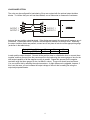
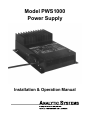
Model PWS1000
Power Supply
Installation & Operation Manual
INTRODUCTION
All new Current Mode switching design offers increased power and reliability in a compact package.
Extra input and output filtering reduce EMI to extremely low levels. Reliability features include an
input fuse, thermal shutdown, current limiting and output short circuit shutdown with automatic
recovery. The output voltage is easily adjusted 0.5 volts above or below the standard output voltage.
The model PWS1000 Power Supply supplies either 12, 24 or 48 VDC from a 110 or 220 VAC power
source. 1 or 2 high quality analog meters can be added (factory option) to allow monitoring of
charging current and charging voltage. Other output voltages up to 72 volts are also available by
special order.
SPECIFICATIONS
PWS1000-ip-op
Input Voltages
Nominal (ip)
Actual
Input Amps (max)
Output Voltages
Nominal (op)
Actual
Adjust
Output Crowbar
Output Amps (cont)
Output Amps (max)
General
Input Frequency
Noise on Input
Noise on Output
Transient Response
Efficiency
Temp. Range
Isolation
Isolation
Length
Width
Height
Clearance
Material
Finish
Fastenings
Weight
110Vac
105 - 125Vac
11.3(12V) / 14.6(24/48V)
12Vdc
13.6 ± 0.05Vdc
16.0 ± 0.5 Vdc
60
70
220Vac
210 - 250Vac
5.7(12V) / 7.3(24/48V)
24Vdc
27.2 ± 0.05Vdc
± 0.5
32.0 ± 1.0 Vdc
40
45
48Vdc
54.4 ± 0.10Vdc
63.9 ± 2.0 Vdc
20
22.5
45 - 65 Hz
< 50 milli-Volts
< 50 milli-Volts
< 1 V for 30A 12Vdc Out < 1 V for 20A 24Vdc Out < 1 V for 9.5A 48Vdc Out
> 80 % @ maximum output
0 – 40 deg. C @ maximum output
Input-Output & Input-Case 1500VDC
Output-Case 500VDC
14.5 in / 36.8 cm
10.2 in / 25.9 cm
5.5 in / 14.0 cm
1 Inch (2.5 cm) all around
Marine Grade Aluminum
Black Powder Epoxy
18-8 Stainless
12 lb / 5.5 kg
designed and manufactured by:
ANALYTIC SYSTEMS WARE (1993) LTD.
#207 12448 82 Ave. Surrey, B.C., V3W 3E9, Canada
phone (604) 543-7378
fax (604) 543-7354
toll free 800-668-3884 US/Canada
email: [email protected]; web site: www.analyticsystems.com
Specifications subject to change without notice.
1
Revised Oct 2000
IMPORTANT SAFETY INSTRUCTIONS
1) SAVE THESE INSTRUCTIONS — This manual contains important safety and operating
instructions for power supply.
2) Do not expose power supply to rain or snow.
3) Use of an attachment not recommended or sold by the power supply manufacturer may
result in a risk of fire, electric shock, or injury to persons.
4) Do not disassemble power supply; take it to a qualified serviceman when service or repair
is required. Incorrect reassembly may result in a risk of electric shock or fire.
5) To reduce risk of electric shock, unplug power supply from outlet before attempting any
maintenance or cleaning. Turning off controls will not reduce this risk.
6) Never place marine power supply directly above battery; gases from battery will corrode
and damage power supply.
7) Never allow battery acid to drip on power supply when reading gravity or filling battery.
GROUNDING AND AC POWER CORD CONNECTION INSTRUCTIONS — The plug must be
plugged into an outlet that is properly installed and grounded in accordance with al local codes and
ordinances.
DANGER — Never alter AC cord or plug provided — if it will not fit outlet, have proper cord installed
by a qualified electrician. Improper connection can result in a risk of an electric shock.
Analytic Systems does not recommend the use of the PWS1000 Series Power Supplies in life
support applications where failure or malfunction of this product can be reasonably expected to cause
failure of the life support device or to significantly affect its safety or effectiveness. Analytic Systems
does not recommend the use of any of its products in direct patient care.
Examples of devices considered to be life support devices are neonatal oxygen analyzers, nerve
stimulators (whether used for anesthesia, pain relief, or other purposes), autotransfusion devices,
blood pumps, defibrillators, arrhythmia detectors and alarms, pacemakers, hemodialysis systems,
peritoneal dialysis systems, neonatal ventilator incubators, ventilators for both adults and infants,
anesthesia ventilators, and infusion pumps as well as any other devices designated as "critical" by the
U.S. FDA.
2
INSTALLATION
MOUNTING
Mount the unit in a DRY location. Allow at least 4 inches of clearance around the heat sink fins for
adequate cooling.
POWER CONNECTION
The unit is supplied with a 5 foot power cable. This should normally be adequate to connect to a
source of power. If you must extend the power cable be sure to use a 3 conductor grounded type
extension cable. For hard wiring to a source of power, cut off the plug, and strip the wires as
necessary. The wire colours are
110 VAC
220 VAC
Black - AC Hot
White - AC Neutral
Green – Ground
Brown - AC Hot
Light Blue - AC Neutral
Green – Ground
All connections should be made inside an appropriate junction box. The maximum current draw from
the 110 VAC supply is 14.6 amps, so a 20 amp circuit breaker should be used in the circuit panel and
for a 220 VAC supply, 7.3 amps is the maximum current draw, so a 10 amp circuit breaker should be
used in the circuit panel to feed power to the PWS1000.
OUTPUT CONNECTIONS
Two Positive output terminals and two Negative output terminals are provided. Connect only one wire
to each terminal. Ensure that the total average load connected does not exceed the continuous
current rating of the unit.
OPERATION
Turn the switch on the top of the unit on to energize the outputs. The green indicator light will glow to
indicate the proper operation of the unit.
OUTPUT ADJUSTMENT
As shipped from the factory, the unit is preset to 13.6, 27.2 or 54.4VDC. You may check this voltage
at the output terminals of the unit with a good digital voltmeter. If you wish to adjust the output
voltage, remove the cover plate (secured by 2 screws) to expose the output adjust potentiometer.
Reach in with a very small flat blade screwdriver to rotate the potentiometer. Clockwise increases the
output voltage, and counter clockwise decreases it. When you are done, replace the cover plate and
securely tighten the screws.
METERS
1 or 2 high quality 2 ½ inch analog meters can be added to the charger (factory installed only). 1
ammeter allows monitoring of total output current. 2 ammeters allow independant monitoring of the
current into each of the output terminals. 1 ammeter and 1 voltmeter allow monitoring of total output
current and output voltage.
3
LOAD SHARE OPTION
The units may be configured for load sharing if they are equiped with the optional output isolation
diodes. To confirm that your unit has these diodes, use an ohmmeter to measure the resistance
OUTPUT 1
OUTPUT 2
OUTPUT 1
OUTPUT 2
between the two positive output terminals. If the diodes are present the terminals will measure as not
connected. If the diodes are NOT present, the terminals will measure as a short circuit. Assuming
the output isolation diodes are present, connect one 4 foot piece of red wire of the appropriate gauge
(as shown in the table below)
Output Voltage (Vdc)
Wire Gauge (AWG)
12
#8
24
#12
48
#14
to each positive output terminal. Connect all the positive wires to a distribution bus, or connect them
together, and then connect from the common point to the load using the correct gauge of wire for the
total output capability of all the supplies running in parallel. Repeat this process for the negative
terminals using the same gauges of wire, but black in colour. These units should now load share.
You can confirm this by watching the output ammeters. A slight difference is negligable, however, if
this is not the case, you can increase the output voltage of the unit that is reading low using the
output adjust potentiometer.
4
TROUBLE SHOOTING
This unit provides LED indicators and a buzzer to help diagnose any problems. The unit should
sound the buzzer to alert you prior to shutting itself down. You should immediately check the
indicators to determine the cause of the shutdown.
•
LOW OUTPUT
Indicates that the output voltage is below normal because:
• The current demanded by the devices connected to the unit exceeds the
maximum output current rating, thereby causing the output voltage to drop
to maintain the current at the maximum level,
• The input voltage is not high enough for unit to operate,
•
LOW INPUT
Indicates that the input voltage is below normal because:
• The input voltage is not in the correct range for proper operation of the unit.
•
OVERHEAT
Indicates that the power supply is running too hot because:
• Too much power is being drawn, turn off or unplug some devices.
• The power supply is located in a poorly ventilated area.
•
OVERLOAD
Indicates that the load it trying to draw to much current because:
• Too much power is being drawn, turn off or unplug some devices.
If the load exceeds the continuous rating for too long a period, the temperature sensor inside the unit
will turn off the outputs. After the unit cools sufficiently, it will automatically come back on. If this
happens frequently, remount the unit for increased airflow so it cools better.
5
Dry Contact Relay
To use your dry contact output fail relay you must connect a 9-pin D connector to the unit. You must
use pins one and six as is indicated on page 7 in the remote connector diagram.
The relay is factory preset to fail in the closed position when the low output LED and buzzer
come on. If you wish to have the relay fail in the open position when the low output LED and
buzzer come on, you must take the cover off the unit and move the jumper to the other
position on J22. J22 is located next to the relay.
To change the position of the jumper, first turn the unit off and disconnect the unit from both the
power and batteries. Next, turn the unit on for 30 seconds to discharge the capacitors, then turn it off
again. Turn the unit upside down and remove the four screws. Remove the cover and locate J22. It
will be next to the relay as is shown in the above diagram. Simply move the jumper to the desired
position as is shown in the above diagram. Replace the cover and re-install the four screws.
Reconnect the unit to the power and batteries.
6
REMOTE CONNECTOR
This connector is located on the side of the unit.
DRY CONTACT
ALARM RELAY
1
(OPTIONAL)
DRY CONTACT
ALARM RELAY
6
(OPTIONAL)
REMOTE OFF
2
CONNECT TO 5 TO FORCE
POWER SUPPLY TO OFF
OVER TEMP
7
NORMALLY HIGH (+12V)
GOES LOW ON
OVER TEMPERATURE
LOW BATTERY
3
NORMALLY HIGH (+12V)
GOES LOW ON
LOW BATTERY
NOT CONNECTED
8
LOW OUTPUT
4
NORMALLY HIGH (+12V)
GOES LOW ON
LOW OUTPUT
+12 VDC
9
GROUND
5
COMMON FOR SWITCHES
REFERENCE VOLTAGE
FOR REMOTE OFF
Note: All switches are electronic (solid state) not mechanical relays.
REMOTE CONTROL
A remote control panel may be connected to the
converter using a 9-pin D-connector which attaches to
the side of the converter. The remote control panel and
D connector are part of the remote control option. The
remote control panel allows the unit to be operated
remotely as well as duplicating all the diagnostic
indicators and audible alarm.
7
This page left intentionally blank.
8
Limited Warranty
1.
The equipment manufactured by Analytic Systems Ware (1993) Ltd. (the “Warrantor”) is
warranted to be free from defects in workmanship and materials under normal use and
service. This warranty is in effect for 3 years from the date of purchase by the user (the
“Purchaser”).
2.
In case any part of the equipment proves to be defective, the Purchaser should do the
following:
a)
Prepare a written statement of the nature of the defect to the best of the Purchasers
knowledge, and include the date of purchase, the place of purchase, and the
Purchasers name, address and telephone number.
b)
Call Analytic Systems at 1-800-668-3884 or (604) 543-7378 and request a return
material authorization number (RMA).
c)
Return the defective part or unit along with the statement at the Purchasers expense to
the Warrantor; Analytic Systems Ware (1993) Ltd., #207 12448 82nd Ave., Surrey,
B.C., V3W 3E9, Canada.
3.
If upon the Warrantor’s examination the defect proves to be the result of defective material or
workmanship, the equipment will be repaired or replaced at the Warrantor’s option without
charge, and returned to the Purchaser at the Warrantor’s expense.
4.
No refund of the purchase price will be granted to the Purchaser, unless the Warrantor is
unable to remedy the defect after having a reasonable number of opportunities to do so.
5.
Warranty service shall be performed only by the Warrantor. Any attempt to remedy the defect
by anyone else shall render this warranty void.
6.
There shall be no warranty for defects or damages caused by faulty installation or hook-up,
abuse or misuse of the equipment including exposure to excessive heat, salt or fresh water
spray, or water immersion except for equipment specifically stated to be waterproof.
7.
No other express warranty is hereby given and there are no warranties which extend beyond
those described herein. This warranty is expressly in lieu of any other expressed or implied
warranties, including any implied warranty of merchantability, fitness for the ordinary purposes
for which such goods are used, or fitness for a particular purpose, or any other obligations on
the part of the Warrantor or its employees and representatives.
8.
There shall be no responsibility or liability whatsoever on the part of the Warrantor or its
employees and representatives for injury to any person or persons, or damage to property, or
loss of income or profit, or any other consequential or resulting damage which may be claimed
to have been incurred through the use or sale of the equipment, including any possible failure
of malfunction of the equipment, or part thereof.
9.
The Warrantor assumes no liability for incidental or consequential damages of any kind.
9