1
"EEE Yönetmeliğine Uygundur"
"This EEE is compliant with RoHS"
RD@@@HHXG_IM_E_33140-4.indd 60
2012-01-26 오후 1:14:40
DVM PLUS IV
RD✴✴✴HHXG Series
RD✴✴✴HRXG Series
Air Conditioner
installation manual
imagine the possibilities
Thank you for purchasing this Samsung product.
To receive more complete service, please
register your product at
www.samsung.com/register
E S F I P D G Ne Po Hu R DB98-33140A(4)
RD@@@HHXG_IM_E_33140-4.indd 61
2012-01-26 오후 1:14:40
safety information
SAFETY INFORMATION
Before installing an air conditioner, please read this manual thoroughly to ensure that you know how to
safely and efficiently install a new appliance.
DVM PLUS IV air conditioner uses R410A refrigerant.
- When using R410A, moisture or foreign substances may affect the capacity and reliability of the product.
Safety precautions must be taken when installing the refrigerant pipe.
- The designed maximum pressure of the system is 4.1MPa. Select appropriate material and thickness according
to the regulations.
- R410A is a quasi-azeotrope of two refrigerants.
Make sure to charge with liquid phase when filling refrigerant.
If you charge vapour refrigerant, it may affect the capacity and reliability of the product as a result of a change in
the blend of the refrigerant.
Connect the indoor units for R410A refrigerant. Check whether the indoor units can be connected with the
product’s catalogue. (When incorrect indoor units are connected, they cannot operate normally.)
SEVERE WARNING SIGNS
If you don’t follow the safety precautions, there may be a risk of injury or death.
The installation must be done by the manufacturer or its service agent or a
qualified person in order to avoid a hazard.
• Installation by an unqualified person may cause a water leakage, electric shock or fire and so on.
Install the outdoor unit correctly according to the installation manual.
• An incorrect installation may cause a water leakage, electric shock or fire and so on.
Manufacturer is not responsible for accidents due to incorrect installation.
When installing the unit in a small room, take measures in order to keep the refrigerant
concentration from exceeding allowable safety limits in the event of a refrigerant leak.
• Excessive refrigerant concentration in a closed room can lead to oxygen deficiency.
Use certified parts in the market and supplied parts from the factory.
• If you don’t use the certified parts and tools, it can cause trouble to the air conditioner and injury.
If any gas or impurities except R410A refrigerant come into the refrigerant
pipe, serious problem may occur and it may cause injury.
Make sure that there is no leakage after installation.
• Toxic gas may generate when refrigerant gas contacts with fire.
Leak test must be done using Oxygen Free Nitrogen (OFN) gas.
Use the supplied accessories, specified components and tools for the installation.
• Do not use the pipe and the installation product used for the R22 refrigerant.
• Failure to use the specified components can cause the product fall, water leakage, electrical shock,
and fire. (The pipe and flare components used for R22 refrigerant must not be used)
Install the outdoor unit on a hard and even place that can support its weight.
• If the place cannot support its weight, the outdoor unit may fall down and it may cause injury.
Check the following before installation and service work.
• Before welding, remove dangerous and inflammable things that may cause an explosion
and fire around the work.
• Before welding, remove the refrigerant from inside the pipe or the product.
- Leakage of the refrigerant in the pipe while welding could make the pressure of the refrigerant
rise causing the pipe to burst. The explosion could cause severe injury to the installer.
• When welding, use the OFN gas to eliminate oxidation inside the pipe.
02_ safety information
RD@@@HHXG_IM_E_33140-4.indd 2
2012-01-26 오후 1:14:15
Fix the outdoor unit securely on foundation to resist strong wind or earthquake.
• If the outdoor unit is not properly fixed, it turns over and accidents may occur.
The electric work must be done by service agent or qualified persons according to
national wiring regulations and use only rated cable.
• Use certified power cable in the market suggested here and do electric work according
to installation manual otherwise, electric shock or fire may occur.
Make sure of a earthing.
Fix power cable on fixture of outdoor unit securely not to be pulled out by
external force.
• If fixing is incomplete, it can cause trouble with a heat generation, electric shock or fire and so on.
ENGLISH
• Do not connect the earth wire to the gas pipe, water pipe, lighting rod or telephone wire.
If earthing is incomplete, electric shock or fire may occur.
Arrange the cables between the indoor and outdoor unit after connecting.
Attach the cover securely so that the electrical component box cover does
not get loosen.
• If the cover is attached incompletely, it can cause trouble with a heat generation, electric
shock or fire of the terminal board.
Install MCCB and ELB according to installation manual.
• If you do not install the MCCB and ELB, electric shock or fire may occur.
The unit must be plugged into an independent circuit if applicable or
connect the power cable to the auxiliary circuit breaker. An all pole
disconnection from the power supply must be incorporated in the fixed
wiring with a contact opening of >3mm.
When installing, you should turn off the power supply before you control or
adjust power supply.
• Otherwise, this may result in electrical shock.
If the refrigerant gas leaks during the installation, you should ventilate the room.
• Contact of the refrigerant gas with flammable things can cause toxic gas.
This appliance is not intended for use by persons (including children) with
reduced physical, sensory or mental capabilities, or lack of experience and
knowledge, unless they have been given supervision or instruction concerning
use of the appliance by a person responsible for their safety. Children should be
supervised to ensure that they do not play with the appliance.
When the product operates in heat mode during winter time, it operates
protection mode when the outdoor temperature drops below 0°C. Therefore,
supply the power during winter time. If the power is not supplied, compressor
protection mode will not operate and cause product malfunction.
Do not modify the product on your own.
• Potential risk of electric shock, fire, product failure or injury.
CAUTION SIGNS
If you don’t follow the safety precautions, you may get the risk of injury or loss of property.
Do not connect the heater to the outdoor unit and do not install altered duct
as you please.
• The capacity may reduce, electric shock or fire may occur.
Make sure that the condensed water dripping from the drain hose runs out
properly and insulate the drain pipe so that frost does not generate.
• Household goods may get wet if the drain pipe is not properly installed.
safety information _03
RD@@@HHXG_IM_E_33140-4.indd 3
2012-01-26 오후 1:14:15
safety information
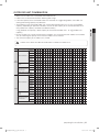
CAUTION SIGNS
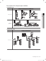
Install the power cable and communication cable of the indoor and outdoor
unit at least 1.5m away from the electric appliances and install it at least 2m
away from the cable from the lightning rod.
• Noise may heard depending on the electric wave though the cables.
• Recommend that use a screened or shielded communication cable.
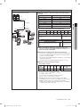
Install the outdoor unit within the angle of 25~55˚ depending on the building
height as below table.
Building height Protective angle
Below 20m
55˚
Remarks
Lightning rod
Protective angle: 25~55˚
Below 40m
35˚
Below 60m
25˚
Building
Install the indoor unit away from lighting apparatus using the ballast.
• If you use the wireless remote control, it may not operate normally.
Do not install the air conditioner in following places.
• T
he place where there is mineral oil or arsenic acid.
Those parts may get damaged due to burned resin.
The efficiency of the heat exchanger may reduce or the air conditioner may be out of order.
• The place where corrosive gas such as sulfurous acid gas generates from the vent pipe
or air outlet.
The copper pipe or connection pipe may corrode and refrigerant may leak.
• The place where there is a machine that generates electromagnetic waves.
The air conditioner may not operate normally due to control system.
• T
he place where there is a danger of existing combustible gas, thinner or gasoline is handled.
• The place where carbon fiber or flammable dust is.
• The place where like spa and shore.
Changes in DVM PLUS IV comparing with conventional models(DVM PLUS III)
• U
se R410A refrigerant.
• Check indoor units, MCU, distributor kits, etc which are connected with DVM PLUS IV
are compatible with DVM PLUS IV or not.
• Version of AVXE and higher is available.
• Make sure the combination method of outdoor units is different from DVM PLUS III.
• The length of maximum piping, level difference, the quantity of connectable indoor units,
the installation at the outdoor joints and the outdoor unit combinations are different from
the conventional models.
• Outdoor joint of gas side pipe should be installed horizontally due to the combination of
variable units when the height of the main pipe is lower than the outlet of the pipe of the
outdoor unit. The Installation of the liquid pipe and high pressure gas pipe are the same.
• If the pipe length between outdoor units becomes 2m or more, install vertical pipe trap to
prevent oil stagnation in the pipes of the outdoor unit in the end of the module, in case of
the outdoor unit in the end of the module stops operating while part loading operation in
system. (Refer to page 26 for details.)
04_ safety information
RD@@@HHXG_IM_E_33140-4.indd 4
2012-01-26 오후 1:14:15
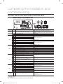
contents
PREPARING THE INSTALLATION
6
15
COMPLETING THE INSTALLATION AND
COMMISSIONING
51
Shape of the outdoor unit
Accessories
Optional accessories
Outdoor unit combination
Selecting appropriate location for installation
Space requirements
When installing 1 outdoor unit
When installing more than 1 outdoor unit
Moving the outdoor unit
Installing the outdoor unit
Anchor specifications
Installing duct for horizontal exhaust discharge
Installing the outdoor unit in harsh environments
Installing the drain pipe
ENGLISH
INSTALLING THE UNIT
6
6
6
7
8
9
9
9
10
11
12
12
13
14
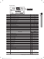
15 Refrigerant piping works
15
Selecting the refrigerant pipe
16
Pipe selection for DVM PLUS IV
18
Pipe selection for DVM PLUS IV HR
20Temper grade and minimum thickness of the
refrigerant pipe
20
Keeping refrigerant pipe clean and dry
20
Brazing the pipe
21
Cutting or flaring the pipes
22
Aligning the pipes
23
Free piping & wiring directions
24
Connecting the outdoor unit pipe
26
Piping works among outdoor units
27The examples of the refrigerant pipe installation
28
Piping examples
30
Installing the branch joints
33
Installing MCU
33
Connecting the pipe
34 Wiring work
34Specifications of the circuit breaker and power
cable
36Power supply and communication cable
configuration
36Specifications of the cable tube
37
Power wiring diagram
40
Selecting solderless ring terminal
41
Connecting the power terminal
42
Power cable arrangement
43
Ground cable arrangement
43
Taking wires out of the outdoor unit
44
Grounding work
45 Performing the refrigerant gas leak test
46 Vacuum drying
47 Insulating the refrigerant pipe
47
Insulating the refrigerant
47Selecting the insulation of the refrigerant pipe
48
Insulating the refrigerant pipe
49
Insulating the branch joint
51 Charging refrigerant
51Important information regulation regarding the
refrigerant used
52
Service valve work for gas pipe
54 Setting the option switches & function keys
54
Option switch of the outdoor unit
55
Key function
56
MCU option switch
57 Completing the installation
58 Final checks and trial operation
58
Inspection before trial operation
59
Trial operation
contents _05
RD@@@HHXG_IM_E_33140-4.indd 5
2012-01-26 오후 1:14:15
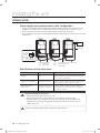
preparing the installation
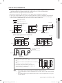
SHAPE OF THE OUTDOOR UNIT
Small size
Large size
RD080/100/120HHXG
RD080/100/120HRXG
RD140/160/180/200HHXG
RD140/160/180/200HRXG
Classification
Shape
Applicable model
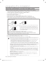
CAUTION
Disposal of packaging material
• Store the packaging material safely or dispose of them.
- Sharp things such as nails and broken wooden packaging material can cause damage to humans.
- Make sure that you keep the vinyl packaging material out of the reach of the children.
Otherwise, placing vinyl material over the face can cause suffocation.
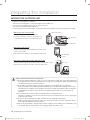
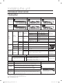
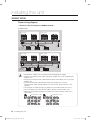
ACCESSORIES
• Keep supplied accessories until the installation is finished.
• Hand the installation manual over to the customer after finishing installation.
• The quantities are indicated in parentheses.
Drain plug
Drain cap
Installation manual
Model
RD080/100/120HHXG
2
2
RD080/100/120HRXG
EA
RD140/160/180/200HHXG
3
3
RD140/160/180/200HRXG
for connecting of drain pipe for closing the drain hole
Remarks
1
1
-
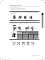
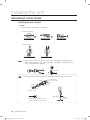
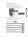
Optional accessories
• The following accessories are needed when installing the outdoor and indoor unit.
Type
Y-joint
Y-joint
(Only for DVM PLUS IV HR module)
Header joint
Outdoor joint
Outdoor joint
(Only for DVM PLUS IV HR module)
Model
MXJ-YA1509
MXJ-YA2512
MXJ-YA2812
MXJ-YA2815
MXJ-YA3119
MXJ-YA3819
MXJ-YA4422
MXJ-YA1500
MXJ-YA2500
MXJ-YA3100
MXJ-YA3800
MXJ-HA2512
MXJ-HA3115
MXJ-HA3819
MXJ-T3819
MXJ-T4422
MXJ-T3100
MXJ-T3800
Total capacity
15.0kW below
15.0~40.6kW
40.6~46.4kW
46.4~69.6kW
69.6~98.6kW
98.6~139.2kW
139.2kW and over
23.2kW and below
23.2~69.6kW
69.6~139.2kW
139.2kW and over
46.4kW and below (For 4 rooms)
69.6kW (For 8 rooms)
69.6kW and over (For 8 rooms)
48HP and below
50HP and over
48HP and below
50HP and over
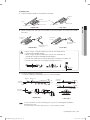
• W
hen the indoor units without EEV such as wall mounted and ceiling type are installed, it is
necessary to install distribution kits.
• It is necessary to install MCU when HR units are installed.
• Distribution kits and MCU should be purchased from the factory.
06_ preparing the installation
RD@@@HHXG_IM_E_33140-4.indd 6
2012-01-26 오후 1:14:15
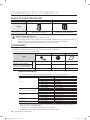
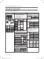
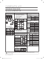
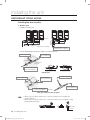
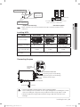
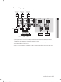
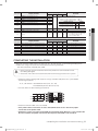
OUTDOOR UNIT COMBINATION
ENGLISH
• Make sure an indoor unit is compatible with DVM PLUS IV
• Indoor units can be connected within following table range.
• If the total capacity of the connected indoor units exceeds the suggested guideline, the indoor unit
cooling and heating capacity may decrease.
• Total capacity of the connected indoor units can be allowed to be from 50% to 130% over outdoor
capacity. (Depending on operation condition, the ratio of total capacity of the connected indoor units
over outdoor unit capacity should be considered carefully.)
0.5x∑ (Outdoor unit capacity) ≤ Total capacity of the connected indoor units ≤ 1.3x∑ (Outdoor unit
capacity)
• Up to 64 indoor units can be connected to an outdoor unit. The communication address of the indoor
unit sets following the quantity of the maximum indoor unit connected.
• The minimum capacity of the indoor unit is 2.2kW.
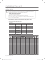
• Make sure to follow the table for combination installation of outdoor units.
CAUTION
Type
Outdoor unit capacity (HP)
8
10
12
14
16
RD080HHXG
1
RD080HRXG
RD100HHXG
RD100HRXG
Outdoor unit combination
RD120HHXG
RD120HRXG
1
Total capacity of the connected
indoor units (cooling)
22
24
26
28
30
32
1
1
2
1
34
36
38
2
1
40
42
44
2
1
1
46
48
50
52
1
1
54
56
58
60
1
2
1
RD160HHXG
RD160HRXG
Nominal
capacity
20
1
1
RD140HHXG
RD140HRXG
High
efficiency
18
1
1
1
1
1
1
1
1
1
1
2
1
1
1
1
1
1
2
2
3
Cooling[kW]
22.4 28.0 33.6 39.2 44.8 50.4 56.0 61.6 67.2 72.8 78.4 84.0 89.6 95.2 100.8 106.4 112.0 117.6 123.2 128.8 134.4
Heating[kW]
25.2 31.5 37.8 44.1 50.4 56.7 63.0 69.3 75.6 81.9 88.2 94.5 100.8 107.1 113.4 119.7 126.0 132.3 138.6 144.9 151.2
Minimum[kW] 11.2 14.0 16.8 19.6 22.4 25.2 28.0 30.8 33.6 36.4 39.2 42.0 44.8 47.6 50.4 53.2 56.0 58.8 61.6 64.4 67.2
Maximum[kW] 29.1 36.4 43.7 51.0 58.2 65.5 72.8 80.1 87.4 94.6 101.9 109.2 116.5 123.8 131.0 138.3 145.6 152.9 160.2 167.4 174.7
Maximum number of connectable indoor
unit
13
17
20
23
26
30
33
36
40
43
46
50
53
2
1
1
1
1
56
60
63
64
64
64
64
64
2
1
1
RD080HHXG
1
RD080HRXG
RD100HHXG
RD100HRXG
1
RD120HHXG
RD120HRXG
Outdoor unit combination
1
1
RD140HHXG
RD140HRXG
1
1
RD160HHXG
RD160HRXG
1
1
RD180HHXG
RD180HRXG
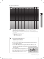
Compact
Total capacity of the connected
indoor units (cooling)
1
1
1
1
RD200HHXG
RD200HRXG
Nominal
capacity
1
1
1
1
1
1
1
1
1
1
1
1
1
1
2
1
1
1
1
1
1
2
2
2
2
3
Cooling[kW]
22.4 28.0 33.6 39.2 44.8 50.4 56.0 61.6 67.2 72.8 78.4 84.0 89.6 95.2 100.8 106.4 112.0 117.6 123.2 128.8 134.4 140.0 145.6 151.2 156.8 162.4 168.0
Heating[kW]
25.2 31.5 37.8 44.1 50.4 56.7 63.0 69.3 75.6 81.9 88.2 94.5 100.8 107.1 113.4 119.7 126.0 132.3 138.6 144.9 151.2 157.5 163.8 170.1 176.4 182.7 189.0
Minimum[kW] 11.2 14.0 16.8 19.6 22.4 25.2 28.0 30.8 33.6 36.4 39.2 42.0 44.8 47.6 50.4 53.2 56.0 58.8 61.6 64.4 67.2 70.0 72.8 75.6 78.4 81.2 84.0
Maximum[kW] 29.1 36.4 43.7 51.0 58.2 65.5 72.8 80.1 87.4 94.6 101.9 109.2 116.5 123.8 131.0 138.3 145.6 152.9 160.2 167.4 174.7 182.0 189.3 196.6 203.8 211.1 218.4
Maximum number of connectable indoor unit
13
17
20
23
26
30
33
36
40
43
46
50
53
56
60
63
64
64
64
64
64
64
64
64
64
64
64
preparing the installation _07
RD@@@HHXG_IM_E_33140-4.indd 7
2012-01-26 오후 1:14:16
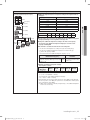
preparing the installation
SELECTING APPROPRIATE LOCATION FOR INSTALLATION
Decide the installation location based on the following condition and obtain the user’s approval.
• Avoid a place that may disturb your neighbor. Noise may occur from the outdoor unit and the discharged air may
run into the neighborhood. (Be careful of the operation time in a residential area)
• Install the outdoor unit on a hard and even area that can support its weight.
• Choose a flat place that rainwater does not settle or leak.
• Choose a place avoiding strong winds.
• Maintain sufficient space for repairs and service.
• Choose a place where you can easily connect the pipes and cables to the indoor unit.
• Make sure that the condensed water dripping from the drain hose runs out properly and safely.
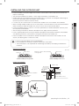
• When installing the outdoor unit near seashore, make sure it is not directly exposed to sea breeze.
If you can not find a adequate place without direct see breeze, protection wall should be constructed.
- Install the outdoor unit in a place (such as near buildings etc.) where it can be prevented from sea breeze which can
damage the outdoor unit.
Outdoor
unit
Sea
breeze
Sea
Sea
breeze
Outdoor
unit
Sea
- If you cannot avoid installing the outdoor unit by the seashore, construct a protection wall around to block the sea
breeze.
Protection wall should be constructed with a solid material such as
Protection
Outdoor
wall
unit
concrete to block the sea breeze and the height and the width of the
wall should be 1.5 times larger than the size of the outdoor unit. Also,
Sea
breeze
secure over 700mm between the protection wall and the outdoor unit
Sea
for exhausted air to ventilate.
- Install the outdoor unit in a place where water can drain smoothly.
If you cannot find a place satisfying above conditions, please contact manufacturer.
Make sure to clean the sea water and the dust on the outdoor unit heat exchanger and spread
corrosion inhibitor on heat exchanger. (At least one time per one year.)
• Choose a place where there is no direct sunlight.
• Choose a place where it could not come into contact with snow and rain.
• Choose a place where flammable gas does not leak.
• Choose a place where the indoor and outdoor unit can be connected with a pipe.
• Install the indoor unit away from any interfering sources such as radio, computer, stereo equipment and
CAUTION
also select the place where the electrical wiring work can be possible.
- Especially keep the unit at least 3m away from the electrical equipment in an area electromagnetic waves
generated and install the protection tube to protect the main power cable and communication cable.
- Make sure that there is no equipment electromagnetic waves generate.
If not, malfunction of the control system may occur due to the effect of the electromagnetic wave.
(For example: The remote control sensor of the indoor unit may not be received well of electronic lighting
style fluorescent lamps, such as fluorescent lamps are in the same space when using a remote control.)
• Make sure to install the outdoor unit in a safe place where snowfall will not be obstructed. The frame should
be installed in a place where the air inlet and heat exchanger of the unit are not buried in the snow.
• A
ventilation system may be required in the case the outdoor unit is installed in a closed space or room,
even though R410a is not poisonous or flammable.
• Install the railing around the outdoor unit to prevent falling when the unit is installed at high place of roof on
the building.
• D
o not install the units in places where corrosive gases such as sulfur oxides, ammonia, and sulfurous gas
are produced. e.g. Toilet outlet, ventilation opening, sewage works, dyeing complex, cattle shed, sulfuric
hot spring, nuclear power plant, ship etc. When installing the units in those places, contact an installation
specialty store as the copper pipe and brazing part will need additional corrosion proof or anti-rust additive
to prevent corrosion.
• Make sure to install MCU when using HR products.
• W
hen you select the location to install MCU, the location is far away from indoor rooms because the
refrigerant running of MCU may create noise.
• A
ccording to the condition of power supply, electric noise or unstable voltage can occur malfunction of
electric parts or control system.
(At the ship or places using power supply from electric generator… etc)
08_ preparing the installation
RD@@@HHXG_IM_E_33140-4.indd 8
2012-01-26 오후 1:14:16
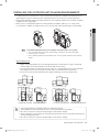
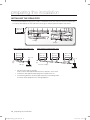
SPACE REQUIREMENTS
Wall height restricted
Wall height unrestricted
When installing 1 outdoor unit
50 or more
300 or
more
100 or
more
Front
50 or more
The height
of the wall is
unlimited
200 or more
< Case 2 >
< Case 1 >
< Case 3 >
When installing more than 1 outdoor unit
10 or more
20 or
more
Front
20 or
more
10 or more
500 or more
100 or more
300 or more
(Unit : mm)
100 or
more
50 or more
< Case 1 >
400 or
more
100 or
more
50 or more
< Case 2 >
The height of the wall
is unlimited
300 or more
200 or more
Front
500 or more
10 or more
500 or
more
Front
200 or more
500 or
more
300 or
more
(Unit : mm)
ENGLISH
• The space suggested below is based on operating condition of outdoor temperature of 35°C.
If operating condition of outdoor temperature is higher than 35°C, try to have more space.
• Make sure to clear a passage for a person and air flow.
• Observe the clearances and dimensions as seen below when installing the outdoor unit.
• If you install several outdoor units at the same place, observe the space for ventilation and free airflow.
• If the space for ventilation is insufficient, the air conditioner may not generate performance designed.
Keep in mind that SAMSUNG logo is located on the front side of outdoor unit.
400 or
more
< Case 3 >
Air inlet
S2+h2/2
500
Front side
S1+h1/2
h2
(Unit : mm)
h1
• The height of the wall should be 1500mm or less in the front
side.
• The height of the wall should be 500mm or less in the air inlet
side.
• The height of the wall is unlimited in the side. • If the height of the wall exceeds the above value, the
additional height (h1)/2, (h2)/2 should be added to the
service space(S1), (S2) individually.
1500
In case of ‘Case 1’ and ‘Case 2’
Note • The installation space mentioned above is minimum suggested clearance.
• To secure enough service space and performance of system, take account of more sufficient
space.
• The required minimum space between outdoor units for service and performance of system
is at least 100mm.
preparing the installation _09
RD@@@HHXG_IM_E_33140-4.indd 9
2012-01-26 오후 1:14:16
preparing the installation
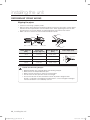
MOVING THE OUTDOOR UNIT
• Select the moving route in advance.
• Be sure that moving route is safe from weight of the outdoor unit.
• Do not slant the product more than 30˚ when carrying it.
(Do not lay the product down sideways.)
• The surface of the heat exchanger is sharp. Be careful not to be get injury while moving and installing.
When moving with a crane or straps
Wire rope/straps
• Fasten the wire rope as seen in the picture.
• To protect damage or scratches, insert a piece of
cloth between the outdoor unit and the wire rope.
Plate protection
cloth
Wooden pallet
When moving with a fork lift
• Insert the fork into the wooden pallet at the bottom of the
outdoor unit carefully.
• Be careful that the fork does not damage the outdoor unit.
When moving without using wooden pallet with a crane
• Connect the wire rope to the outdoor unit as you move it with a crane.
• Attach the wire rope to the fork lift to move the outdoor unit.
CAUTION
Wooden pallet
Fork lift
Fork lift
Wire rope
Safety information before the trial operation.
• When the outdoor temperature is low, turn on the main power supply four hours before operating
- If you operate the machine immediately after turning on the main power supply, severe damage
can be caused to parts inside the machine.
• Do not touch the refrigerant pipe during the operation or immediately after the operation.
- While the outdoor unit is operating and immediately after the operation, the pipe is hot or cold
according to the condition of the refrigerant that flows through the refrigerant pipe, compressor,
and refrigerant cycle parts and if you touch the pipe during this time, it can cause burns or
frostbite.
• Do not operate the machine without the product panel and protective net.
- Otherwise, accidents can result from the contact with the components that are hot, spinning or
under the high-voltage.
• Do not turn off the main power supply immediately after stopping the operation.
- Before turning off the main power supply, you should wait at least 5minutes. Otherwise, water
leaks and other problems can be caused.
• Execute the auto address setting while the power supply to all the indoor units and outdoor units
is connected. Set the auto address after changing indoor unit PCB as well.
10_ preparing the installation
RD@@@HHXG_IM_E_33140-4.indd 10
2012-01-26 오후 1:14:16
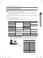
INSTALLING THE OUTDOOR UNIT
CAUTION
ENGLISH
• Install the outdoor unit 200mm higher than the base surface and install the drain hole to connect the
pipe to the drainage.
• The concrete foundation should be 1.5 times larger than bottom of the outdoor unit.
• Condensed water may be generated in heating operation. Pay attention to waterproof and drainage of
the concrete foundation where the outdoor unit is installed.
(An ice may form on the base surface in winter.)
• It is necessary to install wire mesh or steel bar when outdoor units are installed at soft foundation.
• When installing multiple outdoor units at the same place, install the H beam on the concrete foundation.
(When installing a number of outdoor unit, you can install it on the concrete foundation.)
• Install the H beam(150mm x 150mm x t10 : basic specification) or vibration absorption frame to jut out
from the concrete foundation.
• After installing the H beam or vibration absorption frame, apply corrosion protection.
• Install a square pad(t=20mm or more) or vibration absorption frame to prevent vibration of the outdoor
unit delivering to the base surface when installing the concrete for the outdoor unit.
• Place the outdoor unit on the H beam or vibration absorption frame and fix it with the bolt, nut and
washer. (The bearing force is more than 3.5kN)
• Do not install the outdoor unit on a wood palette.
• Fix the outdoor unit securely to the base surface with anchor bolts.
• The manufacturer is not responsible for the damage occurred by not keeping standard of the
installation.
Base mount construction
Drain hole
(Unit : mm)
200 or more
Install the outdoor unit horizontally
on the ground
< When installing on the ground >
200 or more
< When installing on the roof >
Outdoor unit installation
Outdoor unit
Anchor bolt
Nut, Spring
washer
Concrete foundation
H beam or vibration
absorption frame
20mm
A
Square pad
H beam
50mm
A+10~20mm or more
200mm or more
preparing the installation _11
RD@@@HHXG_IM_E_33140-4.indd 11
2012-01-26 오후 1:14:17
preparing the installation
Outdoor unit base mount and anchor bolt position
(Unit:mm)
A
Classification
B
765
745
Applicable
model
Small size
RD080/100/120HHXG
RD080/100/120HRXG
Large size
RD140/160/180/200HHXG
RD140/160/180/200HRXG
A
880
1,295
B
740
1,150
Anchor bolt
CAUTION
• When tightening the anchor bolt
- Tighten the rubber washer to prevent the outdoor unit bolt connection part from corroding.
Rubber washer
• When connecting the pipes
- Check the strength of the roof to install the outdoor unit and make sure to have a waterproof
floor of the roof.
- Make sure that a proper drainage system has been put in place around the outdoor unit.
- To protect the internal components of the outdoor unit, secure the pipework entrance to the
unit.
Close the part.
(When the pipe is projected to the front side)
Liquid side pipe
Gas side pipe
Anchor specifications
c
b
m
Size
Diameter of Anchor
drill bit (a) length (b)
M10
14mm
75mm
Sleeve
length (c)
Insert
depth
Fastening
torque
40mm
50mm
30N·m
a
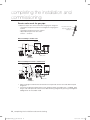
INSTALLING DUCT FOR HORIZONTAL EXHAUST DISCHARGE
• It is necessary to install an air-discharge duct(field supply) to direct exhaust from the fan horizontally
if it is difficult to provide a minimum space of 2m between the air-discharge duct outlet and a nearby
obstacle as shown in the figure.
Discharged air
Upper floor
Gill/Louver
Discharged air
Suction air
Ex) Balcony
Ex) Mechanical room
12_ preparing the installation
RD@@@HHXG_IM_E_33140-4.indd 12
2012-01-26 오후 1:14:17
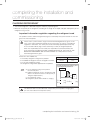
INSTALLING THE OUTDOOR UNIT IN HARSH ENVIRONMENTS
• In abnormally harsh environments such as cold and/or windy areas, sufficient countermeasures to
guard against excessive wind and snow should be taken to ensure the unit’s correct operation.
• Snow-proof duct(field supply) should be fitted to the unit and direct exposure to the wind should be
avoided as much as possible.
• When the unit is expected to operate in cooling mode in condition under 10℃, in snowy areas,
in environments subject to strong winds or rain, install air inlet and outlet ducting as shown below.
ENGLISH
Note
T
he following problems may occur if proper countermeasures are not taken.
• The fan in the outdoor unit may stop running, causing the unit to be damaged.
• There may be no air flow.
• The condenser pressure may drop because of strong wind, and the indoor unit may
freeze.
When installing ducts
•Height of frame/foundation for snow damage prevention shall be twice as high as expected
snowfall, width of frame/foundation shall not exceed that of the unit.
•The frame/foundation shall be made of angle steel, etc., and designed so that snow and wind
slip through the structure. (If frame base is too wide, snow will be accumulated on it.)
•Install unit so that wind will not directly lash against openings of inlet and outlet ducts.
< RD080/100/120HHXG, RD080/100/120HRXG >
CAUTION
< RD140/160/180/200HHXG, RD140/160/180/200HRXG >
•
•
•
•
The frame/foundation should be higher than expected snowfall.
The foundation must be solid and the unit must be secured with anchor bolts.
Be sure to install unit in a place strong enough to withstand its weight.
When installing on a roof subject to strong wind, countermeasures must be taken to prevent the
unit from being overturned.
• Be sure to install unit in a place strong enough to withstand its weight.
preparing the installation _13
RD@@@HHXG_IM_E_33140-4.indd 13
2012-01-26 오후 1:14:18
preparing the installation
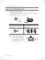
INSTALLING THE DRAIN PIPE
• Insert the provided drain plug at the 2 sides of the bottom of the unit and then connect the drain pipe.
• Install the drain pipe at the rear side of the unit to get a sufficient space for repairs and service.
Outdoor unit
(Rear side)
Drain plug
Drain pipe
When installing single outdoor unit
When installing multiple outdoor units
Outdoor unit
(Rear side)
Outdoor unit
(Rear side)
Outdoor unit
(Rear side)
Open to air
Drain
plug
More than
1/50 slope
Outdoor unit
(Rear side)
Open to air
Drain
plug
More than 1/50 slope
• Do not install a trap on the pipe.
And, install the drain pipe horizontally with a slope of 1/50 or more.
• Insulate the drain pipe and drain plug with insulation over 10t.
• Install heating device to the drain pipe to prevent it from being frozen.
Install the safety equipment for a heating appliance.
14_ preparing the installation
RD@@@HHXG_IM_E_33140-4.indd 14
2012-01-26 오후 1:14:18
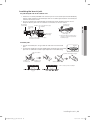
installing the unit
REFRIGERANT PIPING WORKS
WARNING
• The piping length between the outdoor unit and the indoor unit may not exceed the allowable piping
length.
• The pressure of the R410A is high.
Use only certified refrigerant pipe and follow the installation method.
• Use clean refrigerant pipe which there is no harmful ion, oxide, dust, iron content or moisture inside pipe.
• Use tools and accessories fit on R410A.
Tool
Work
Pipe cutter
Flaring tool
Refrigerant oil
Torque wrench
Pipe bender
Nitrogen gas
Brazing tool
Gauge manifold
Refrigerant pipe work
Air tightening test
ENGLISH
When installing, make sure there is no leakage. When recovering the refrigerant, ground the
compressor first before removing the connection pipe.
If the refrigerant pipe is not properly connected and the compressor works with the service valve
open, the pipe inhales the air and it makes the pressure inside of the refrigerant cycle abnormally
high. It may cause explosion and injury.
If compatible with conventional tool
Pipe cutting
Pipe flaring
Apply refrigerant oil on flared
part
Connect flare joint with pipe
Pipe bending
Inhibition of oxidization
Pipe brazing
Refrigerant charging hose
Air tightening test ~ additional Vacuuming, charging and
refrigerant charging
checking operation
Vacuum pump
Vacuuming unit
Electronic scale
Gas leak detector
Flare joint
Use indoor unit’s only
Gas leak test
Compatible
Ester series oil, alkali
benzene oil or synthetic oil
Compatible
Exclusive
Use one which has a check
valve and 5 torr degree of
vacuum.
Compatible
Exclusive
Selecting the refrigerant pipe
• When the equivalent pipe length from outdoor unit to the farthest indoor unit is over 90m,
the main pipe (both liquid and gas pipe) has to be increased with 1 size like below table.
The pipe length between outdoor
and the farthest indoor unit
Below 90m
Main pipe First branch Equivalent pipe length between outdoor
joint
unit and the farthest indoor unit
Main pipe : from outdoor unit to the first branch joint.
90m and over
ø9.52
ø12.70
ø12.70
ø15.88
ø15.88
ø19.05
ø19.05
ø22.23
ø22.23
ø25.40
ø25.40
ø28.58
ø28.58
ø31.75
ø31.75
ø38.10
ø38.10
ø44.45
ø44.45
ø50.80
installing the unit _15
RD@@@HHXG_IM_E_33140-4.indd 15
2012-01-26 오후 1:14:19
installing the unit
REFRIGERANT PIPING WORKS
Pipe selection for DVM PLUS IV
12HP
14HP
(A1)
(A1)
(A1)
(A2)
Outdoor unit connection pipe size : (A1), (A2), (A3)
A1 : Select the pipes according to the outdoor
unit capacity with following table.
A2 : Select the pipes according to sum of
outdoor unit capacities behind the outdoor
joint with following table.
A3 : Select the main pipe of outdoor units with
the following table.
16HP
(E)
(B)
(A3)
(D)
(F)
(C)
• Example) 42HP of compact
combinations
Pipe size
(O. D.mm)
HP Mark
Liquid Gas
12
(A1)
Ø12.70
Ø25.40
14
(A1)
Ø12.70
Ø25.40
16
(A1)
Ø12.70
Ø28.58
26
(A2)
Ø19.05
Ø31.75
42
(A3)
Ø19.05
Ø38.10
Outdoor
unit
8HP
10HP
12HP
14HP
16HP
18HP
20HP
22HP
24HP
26~30HP
32~34HP
36~48HP
50~60HP
Pipe size (O.D. mm), (A)
Liquid
Gas
Ø9.52
Ø12.70
Ø15.88
Ø19.05
Ø22.23
Oil
balancing
pipe size
Ø19.05
Ø22.23
Branch joint : (D), (E), (F)
Branch joint of outdoor unit’s multi
connection (D)
Outdoor multi
Model
connection
branch joint MXJ-T3819
(D)
MXJ-T4422
Y-joint
(E)
Ø6.35
Ø31.75
Ø38.10
Ø44.45
*A1 : Pipes to the outdoor unit (Liquid, Gas)
*A2 : Pipes between outdoor joint kits (Liquid, Gas)
*A3 : Main pipes (Liquid, Gas)
Pipe size between branch joints : (B)
Select the pipe size according to the capacity sum of
indoor units which are connected below this pipe.
Total indoor unit’s Pipe size (O. D. mm)
capacity
Liquid
Gas
Below 48 HP
Above 50 HP
First branch joint (E)
Select branch joint according to the outdoor
unit’s capacity.
Ø25.40
Ø28.58
Capacity of
outdoor
Outdoor unit
Model
8~14HP
MXJ-YA2512
16HP
MXJ-YA2812
18~24HP
MXJ-YA2815
26~34HP
MXJ-YA3119
36~48HP
MXJ-YA3819
50~60HP
MXJ-YA4422
Branch joint (F)
Select the pipe size according to the
capacity sum of indoor units which are
connected below this pipe.
1) Y-joint
Model
Total indoor unit’s
capacity
MXJ-YA1509 15.0kW and below
MXJ-YA2512 Over 15.0~40.6kW and below
Y-joint MXJ-YA2812 Over 40.6~46.4kW and below
(F)
MXJ-YA2815 Over 46.4~69.6kW and below
Ø15.88
MXJ-YA3119 Over 69.6~98.6kW and below
Ø19.05
MXJ-YA3819 Over 98.6~139.2kW and below
Over 23.2~29.0kW and below
Ø22.23
MXJ-YA4422 Over139.2kW
Over 29.0~40.6kW and below
Ø25.40
15.0kW and below
Over 15.0~23.2kW and below
Over 40.6~46.4kW and below
Over 46.4~69.6kW and below
Over 69.6~98.6kW and below
Over 98.6~139.2kW and below
Over 139.2kW
Ø9.52
Ø12.70
Ø15.88
Ø19.05
Ø22.23
Ø31.75
Ø38.10
Ø44.45
Pipe size between branch joints and
indoor unit (C)
Select the pipe size according to the indoor
unit’s capacity.
Indoor unit’s
capacity
2) Header joint
Ø28.58
Model
Total
The
indoor connectable
unit’s
quantity of
capacity indoor units
Header
0~46.4kW
joint MXJ-HA2512 and below
(F)
Over 46.4kW
4
MXJ-HA3115 ~ 69.6kW
and below
8
MXJ-HA3819 Over 69.6kW
8
Pipe size (O. D. mm)
Liquid
Gas
2.0~5.6kW
Ø6.35
Ø12.70
7.2∼14.5kW
Ø9.52
Ø15.88
16_ installing the unit
RD@@@HHXG_IM_E_33140-4.indd 16
2012-01-26 오후 1:14:19
Additional refrigerant charging
• Example) Additional refrigerant charging
Additional refrigerant has to be charged according to the length and size of
liquid pipe.
Liquid pipe size (O.D. mm)
50.4kW
Ø12.70(1m)
Ø12.70(5m)
Ø19.05(5m)
Ø9.52(10m)
Ø15.88(10m)
Ø9.52(10m)
7.1kW
Ø6.35(5m)
7.1kW
0.18
ø19.05
0.27
ø22.23
0.35
ø25.40
0.53
Standard
Ø6.35(10m)
7.1kW
0.125
ø15.88
Classification
7.1kW
Ø6.35 Ø6.35
(10m) (5m)
0.06
ø12.70
The amount of the refrigerant that is already placed in
5.6kW Ø9.52(10m) Ø12.70(15m)
5.6kW
0.02
ø9.52
ENGLISH
Ø15.88(10m)
5.6kW
Additional refrigerant charging (kg/m)
ø6.35
8HP 10HP 12HP 14HP 16HP 18HP 20HP
5.0
5.0
5.0
7.0
7.0
8.5
8.5
For the indoor unit connected to the distribution kit, the additional refrigerant
charging is 0.01kg per meter regardless of the pipe size.
Charge the additional refrigerant according to the indoor unit capacity.
The amount of the additional refrigerant charging for each indoor unit
capacity = 0.046kg/kW
The method to calculate the total amount of the refrigerant.
- The amount of the refrigerant according to the pipe size and length (ⓐ)
- The amount of additional refrigerant charging for each indoor unit (ⓑ) =
∑ (Indoor unit capacity) x 0.046
- The total amount of the additional refrigerant charging = ⓐ+ⓑ
Additional refrigerant charging of
distribution kit (kg/m)
Regardless of the liquid pipe size, additional
refrigerant charging is 0.01 kg per meter after
distribution kit
Remarks
0.01
For wall-mounted & ceiling
indoor unit
E
xample of additional refrigerant charging.
Pipe length is as below.
Liquid pipe size
(O.D. mm)
Ø6.35
Ø9.52
Ø12.70
Ø15.88
Ø19.05
Length (m)
30
30
21
20
5
❈ ⓐ = 30x0.02 +30x0.06 + 21x0.125 + 20x0.18 + 5x0.27 = 9.975kg
ⓑ = (7.1x4 + 5.6x3)x0.046 = 2.079kg
The total amount of the additional refrigerant charging :
ⓐ+ⓑ = 9.975 + 2.079 = 12.054kg
❈ Total refrigerant amount of the system must be less than 100kg. If total refrigerant
amount of system is over 100kg, the system has to be divided into smaller system,
each containing less than 100kg.
ex) 20HP outdoor refrigerant is already charged 8.5kg, so the additional refrigerant
must not be over 91.5kg.
installing the unit _17
RD@@@HHXG_IM_E_33140-4.indd 17
2012-01-26 오후 1:14:19
installing the unit
REFRIGERANT PIPING WORKS
Pipe selection for DVM PLUS IV HR
12HP
14HP
(A1)
(A1)
(A1)
(A2)
Outdoor unit connection pipe size : (A1), (A2), (A3)
A1 : Select the pipes according to the outdoor
unit capacity with following table.
A2 : Select the pipes according to sum of
outdoor unit capacities behind the outdoor
joint with following table.
A3 : Select the main pipe of outdoor units with
the following table.
16HP
(E)
(A3)
(B)
(F)
(D)
(C)
• Example) 42HP of compact
combinations
Pipe size
(O. D.mm)
HP Mark
High
Liquid Low
gas gas
Pipe size (O.D. mm), (A)
Oil
Outdoor
balancing
High
unit
Liquid Gas
gas pipe size
8HP
10HP
12HP
14HP
16HP
18HP
20HP
22HP
24HP
26~30HP
32~34HP
36~48HP
50~60HP
Ø19.05 Ø15.88
Ø9.52
Ø22.23 Ø19.05
Ø12.70
Ø15.88
Ø19.05
Ø25.40
Ø28.58
Ø22.23
Ø25.40
Ø6.35
Branch joint of outdoor unit’s multi
connection (D)
Model
Liquid & Low MXJ-T3819
gas pipe
MXJ-T4422
High gas pipe
Ø38.10 Ø31.75
Ø22.23 Ø44.45 Ø38.10
*A1 : Pipes to the outdoor unit (Liquid, Gas, High pressure gas)
*A2 : Pipes between outdoor joint kits
(Liquid, Gas, High pressure gas)
*A3 : Main pipes (Liquid, Gas, High pressure gas)
(A1)
Ø12.70
Ø25.40 Ø22.23
14
(A1)
Ø12.70
Ø25.40 Ø22.23
16
(A1)
Ø12.70
Ø28.58 Ø22.23
Pipe size between branch joints : (B)
26
(A2)
Ø19.05
Ø31.75 Ø28.58
42
(A3)
Ø19.05
Ø38.10 Ø31.75
Select the pipe size according to the capacity sum of
indoor units which are connected below this pipe.
Total indoor unit’s
capacity
Pipe size (O.D. mm)
Liquid Gas High
gas
Ø15.88
15.0kW and below
Over 15.0~23.2kW and below
Ø9.52 Ø19.05
Ø15.88
MXJ-T3100
MXJ-T3800
Capacity of
outdoor
Below 48 HP
Above 50 HP
Below 48 HP
Above 50 HP
First branch joint (E)
Select branch joint according to outdoor
unit’s capacity.
Liquid
& Low
pressure
gas Y-joint
(E)
Ø31.75 Ø28.58
12
High
pressure
gas Y-joint
(E)
Outdoor unit
Model
8~14HP
16HP
18~24HP
26~34HP
36~48HP
50~60HP
MXJ-YA2512
MXJ-YA2812
MXJ-YA2815
MXJ-YA3119
MXJ-YA3819
MXJ-YA4422
Outdoor unit
Model
8HP
10~24HP
26~48HP
50~60HP
MXJ-YA1500
MXJ-YA2500
MXJ-YA3100
MXJ-YA3800
Branch joint (F)
Model
Liquid
& low
pressure
gas Y-joint
(F)
Total indoor unit’s
capacity
MXJ-YA1509 15.0kW and below
MXJ-YA2512 Over 15.0~40.6kW and below
MXJ-YA2812 Over 40.6~46.4kW and below
MXJ-YA2815 Over 46.4~69.6kW and below
MXJ-YA3119 Over 69.6~98.6kW and below
Over 23.2~29.0kW and below
Ø22.23 Ø19.05
MXJ-YA3819 Over 98.6~139.2kW and below
Over 29.0~40.6kW and below
Over 40.6~46.4kW and below
Over 46.4~69.6kW and below
Ø12.70
Ø25.40
MXJ-YA4422 Over 139.2kW
Over 69.6~98.6kW and below
Ø19.05
Over 98.6~139.2kW and below
Over 139.2kW
Ø15.88
Ø28.58
Ø22.23
Ø25.40
Ø31.75 Ø28.58
Ø38.10 Ø31.75
Ø22.23 Ø44.45 Ø38.10
Pipe size between branch joints and indoor unit : (C)
Select the pipe size according to the indoor
unit’s capacity.
Indoor unit’s
capacity
2.2~5.6kW
7.1~14.0kW
CAUTION
Branch joint : (D), (E), (F)
Total indoor unit’s
Model
capacity
High
pressure MXJ-YA1500 23.2kW and below
gas Y-joint MXJ-YA2500 Over 23.2~69.6kW and below
MXJ-YA3100 Over 69.6~139.2kW and below
(F)
MXJ-YA3800 Over 139.2kW
Pipe size (O. D. mm)
Liquid
Gas
Ø6.35
Ø9.52
Ø12.70
Ø15.88
The sum of the total capacity of the indoor units connected to a MCU should not be over
the max. 44.8kW.
18_ installing the unit
RD@@@HHXG_IM_E_33140-4.indd 18
2012-01-26 오후 1:14:20
Additional refrigerant charging
Additional refrigerant is charged according to the length and size of
liquid pipe.
• Example) Additional refrigerant charging
61.6kW
Ø12.70(1m)
Ø12.70(5m)
Ø19.05(10m)
MCU
Ø9.52
(10m)
Ø6.35(2m)
Ø9.52
(15m)
7.1kW
Ø9.52
(25m)
7.1kW
11.2kW
Ø9.52(15m)
0.125
Ø15.88
0.18
Ø19.05
0.27
Ø22.23
0.35
Ø25.40
0.53
Standard
5.0
5.0
5.0
7.0
7.0
Additional refrigerant charging of MCU kit
Additional refrigerant charging of MCU is 0.5kg for
every MCU kit
8.5
8.5
(kg/unit)
0.5
7.1kW
7.1kW
Ø9.52(18m)
Ø9.52(18m)
0.06
Ø12.70
Classification 8HP 10HP 12HP 14HP 16HP 18HP 20HP
Ø6.35(10m)
2.8kW
11.2kW
0.02
Ø9.52
The amount of the refrigerant that is already placed in
MCU
Ø6.35(15m)
Additional refrigerant charging (kg/m)
Ø6.35
ENGLISH
Ø15.88(10m) Ø15.88(10m)
Liquid pipe size (O.D. mm)
7.1kW
Additional refrigerant charging of
distribution kit (kg/m)
Regardless of the liquid pipe size, additional
refrigerant charging is 0.01kg per meter after
distribution kit
Remarks
0.01
For wall-mounted &
ceiling indoor unit
Charge the additional refrigerant according to the indoor unit
capacity. The amount of the additional refrigerant charging for each
indoor unit capacity = 0.046kg/kW
The method to calculate the total amount of the refrigerant.
- The amount of the refrigerant according to the pipe size and length (ⓐ)
- The amount of additional refrigerant charging for each indoor unit (ⓑ) =
∑ (Indoor unit capacity) x 0.046
- The amount of other additional refrigerant charging (ⓒ) = ∑(The number
of MCU Kit installed) x 0.5
- The total amount of the additional refrigerant charging = ⓐ+ⓑ+ⓒ
E
xample of additional refrigerant charging.
Pipe length is as below.
Liquid pipe
Pipe length after
size Ø6.35 Ø9.52 Ø12.70 Ø15.88 Ø19.05 MCU distribution kit
(O.D. mm)
(m)
2 Ea
2
6
20
10
Length (m) 25 101
❈ ⓐ = 25x0.02 +101x0.06 + 6x0.125 + 20x0.18 + 10x0.27 = 13.61kg
ⓑ = (11.2x2 + 7.1x5 + 2.8x1)x0.046 = 2.7922kg
ⓒ = 2x0.01 + 2x0.5 = 1.02
The total amount of the additional refrigerant charging :
ⓐ+ⓑ+ⓒ = 13.61 + 2.792 + 1.02 = 17.422kg
❈ Total refrigerant amount of the system must be less than 100kg.
If total refrigerant amount of system is over 100kg, the system has to be
divided into smaller system, each containing less than 100kg.
ex) 20HP outdoor refrigerant is already charged 8.5kg, so the additional
refrigerant must not be over 91.5kg.
installing the unit _19
RD@@@HHXG_IM_E_33140-4.indd 19
2012-01-26 오후 1:14:20
installing the unit
REFRIGERANT PIPING WORKS
Temper grade and minimum thickness of the refrigerant pipe
Outer diameter [mm]
Minimum thickness [mm]
Ø6.35
Ø9.52
Ø12.70
Ø15.88
Ø19.05
Ø22.23
Ø25.40
Ø28.58
Ø31.75
Ø38.10
Ø44.45
Ø50.80
CAUTION
Temper grade
0.7
0.7
0.8
1.0
0.9
0.9
1.0
1.1
1.1
1.35
1.6
2.0
C1220T-O
C1220T-1/2H
or
C1220T-H
Make sure to use C1220T-1/2H (Semi-hard) pipe for more than Ø19.05mm. In case of using
C1220T-O (Soft) pipe for Ø19.05mm, pipe may be broken, which can result in an injury.
Keeping refrigerant pipe clean and dry
To prevent foreign materials or water from entering the pipe, it is important to keep the refrigerant
pipe clean and dry and to seal it during installation.
Exposure place
Outside exposure
Inside exposure
Exposure time
Sealing type
Longer than one month
Shorter than one month
-
Pipe pinch
Taping
Taping
Brazing the pipe
•
•
•
•
Make sure that there is no moisture inside the pipe.
Make sure that there are no foreign materials and impurities in the pipe.
Make sure that there is no leak.
Make sure to follow the instruction when brazing the pipe.
The use of Nitrogen gas
1.Use Nitrogen gas when brazing the pipes as shown
in the picture.
2.If you do not use Nitrogen gas when brazing the
pipes, oxide may form inside the pipe. It can cause
the damage of the compressor, valves.
3.Adjust the flow rate of the Nitrogen gas with a
pressure regulator to maintain 0.05m3/h or less.
Brazing part
1/4" copper pipe
Nitrogen gas
Pressure regulator
Stop valve
Taping
Flowmeter
Direction of the pipe when brazing
• Performing the brazing of the pipe should be headed downward or horizontally.
Downward
Note
Side
Upward
Avoid brazing the pipe upward.
20_ installing the unit
RD@@@HHXG_IM_E_33140-4.indd 20
2012-01-26 오후 1:14:20
Cutting or flaring the pipes
To prevent foreign materials or water from entering the pipe, it is important to keep the refrigerant pipe clean
and dry and to seal it while installing.
1. Make sure that you prepared the required tools.
(pipe cutter, reamer, flaring tool and pipe holder)
Oblique
Rough
Burr
ENGLISH
2. If you want to shorten the pipe, cut it using a pipe cutter ensuring that the cut edge remains
at 90° with the side of the pipe. There are some examples of correctly and incorrectly cut
edges below.
3. To prevent a gas leak, remove all burrs at the cut edge of the pipe using a reamer.
4. Carry out flaring work using flaring tool as shown below.
Flaring tool
A
York
Flaring bar
Flaring bar
Clutch type
Wing nut type
Outer diameter
(mm)
Copper pipe
Flare tool for
R410A clutch type
Flare joint
Copper pipe
A(mm)
Conventional flare tool
Clutch type
Wing nut type
ø6.35
0 ~ 0.5
1.0 ~ 1.5
1.5 ~ 2.0
ø9.52
0 ~ 0.5
1.0 ~ 1.5
1.5 ~ 2.0
ø12.70
0 ~ 0.5
1.0 ~ 1.5
1.5 ~ 2.0
ø15.88
0 ~ 0.5
1.0 ~ 1.5
1.5 ~ 2.0
5. Check if you flared the pipe correctly. There are some examples of incorrectly flared pipes
below.
Correct
Inclined
Damaged
surface
Cracked
Uneven
thickness
installing the unit _21
RD@@@HHXG_IM_E_33140-4.indd 21
2012-01-26 오후 1:14:21
installing the unit
REFRIGERANT PIPING WORKS
Aligning the pipes
• Check that the flaring is properly made.
• Align the center of the piping and sufficiently tighten the flare nut with fingers. Finally, tighten
the flare nut with torque wrench until the wrench clicks. When tightening the flare nut with
torque wrench, ensure the direction for tightening follows the arrow on the wrench.
• Make sure to use ester oil to coat the flare connection section.
Pipe
Flare joint
Connection torque (kgf•cm)
Flare dimension (mm)
ø6.35
145~175
8.70 ~ 9.10
ø9.52
333~407
12.80 ~ 13.20
ø12.70
505~615
16.20 ~ 16.60
ø15.88
630~769
19.30 ~ 19.70
Flare shape (mm)
45° ± 2°
Outer diameter (mm)
90° ± 2°
Flare connection section
R 0.4~0.8
Caution for connecting the pipe
CAUTION
•
•
•
•
•
lowing Nitrogen gas should be done when brazing the pipe.
B
Make sure to use the provided flare joint.
Make sure that there are any cracks on the bent pipe.
Do not fasten the flare joint with excessive strength.
Use ester oil to coat the flare connection section to prevent refrigerant leak.
R410A is a high pressure refrigerant therefore there is a risk of refrigerant leakage if
the flare connection is not coated by ester oil.
22_ installing the unit
RD@@@HHXG_IM_E_33140-4.indd 22
2012-01-26 오후 1:14:21
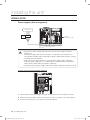
Free piping & wiring directions
DVM PLUS IV is easy to install as its piping can be connected from front, right, left and bottom
side. Wiring hole (Conduits) adds convenience as it allows power and communication lines to be
connected in various ways and directions.
ENGLISH
Front side
Left side
Right side
Caution for using knock-out hole
CAUTION
• M
ake sure not to damage the exterior of the outdoor unit.
• Remove all burrs at the edge of the knock-out hole and apply the paints it to prevent
rust.
• Use a cable tube and bushing to prevent a cable from being damaged when passing
through a knock-out hole.
Knock-out hole
installing the unit _23
RD@@@HHXG_IM_E_33140-4.indd 23
2012-01-26 오후 1:14:21
installing the unit
REFRIGERANT PIPING WORKS
Connecting the outdoor unit pipe
Heat Pump
Connection from front side
Connection from bottom at the
left/right side
• First, remove the cover from unit.
• Separate the knock-out hole at the
• Separate the knock-out hole to use.
bottom side of the unit and install
If the hole is open, small animals such as the pipe.
squirrels and rats may get into the unit
• After installing and insulating the pipe,
Working process
through the hole and the unit may be
close up the remaining gap. If the gap is
damaged.
remain open, small animals such as rats
• Fix the pipe cover of bottom side and fix
and squirrels may get inside the unit and
the pipe cover of upper side thereafter.
cause damage to the unit.
Single
installation
Combination
installation
Gas side
pipe
Gas side
pipe
Liquid
side
pipe
Oil
balancing
valve
Liquid
side
pipe
Gas side
pipe
Gas side
pipe
Liquid
side
pipe
Oil
balancing
valve
Liquid
side
pipe
24_ installing the unit
RD@@@HHXG_IM_E_33140-4.indd 24
2012-01-26 오후 1:14:22
Heat Recovery
Gas pipe
Liquid
pipe
Oil
balancing
valve
High
pressure
gas pipe
Gas pipe
Combination
installation
Liquid
pipe
Oil
balance
pipe
Oil
balancing
valve
Connection from bottom at the
left/right side
Oil
balancing
valve
Gas pipe
Liquid
pipe
High
pressure
gas pipe
Gas pipe
Oil
balancing
pipe
Liquid
pipe
Oil
balancing
valve
ENGLISH
Single
installation
Connection from front side
High
pressure
gas pipe
High
pressure
gas pipe
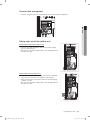
Caution for connecting the pipe
CAUTION
• When connecting the pipe to the unit, the unit may get
damaged by a welding fire and a flame. Use a flame proofing
cloth to protect the unit from a welding fire or flame.
Ambient air temperature sensor for detecting outside
temperature is located on the left side of the welding part.
Make sure not to damage the temperature sensor when welding it.
• The O-ring and Teflon packing inside service valve may get
damaged by a welding fire. Wrap the bottom side of the service
valve with a wet cloth and weld it as shown above. Make sure
not to interrupt the welding with the drops of the wet cloth.
• The connecting pipes of liquid side and gas side should not
contact each other.
Vibration may cause a damage to the pipes.
Service valve
Filling port
Wet towel
Temperature sensor
installing the unit _25
RD@@@HHXG_IM_E_33140-4.indd 25
2012-01-26 오후 1:14:24
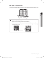
installing the unit
REFRIGERANT PIPING WORKS
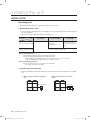
Piping works among outdoor units
• The additional branch joints are needed for module installation of the outdoor units.
• When outdoor units are installed in module, there is no designation of outdoor unit’s location
according to capacity.
• The connected piping should be positioned at the same level with pipe cover hole or lower.
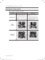
✴Note the changes of DVM PLUS III, IV by comparing to DVM PLUS II
Cautions
Correct piping work
Wrong piping work
The refrigerant piping
should be the
same level or lower
than connecting
position of piping to
outdoor units.
Piping work should
be run with side
direction for better
uniform distribution
of refrigerant and oil
like next diagram.
Outdoor joint kits
should be installed in
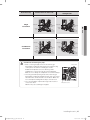
a horizontal direction,
even it is a low
pressure pipe.
When the piping
length between
outdoor and branch
joints is 2m or
more, a vertical trap
has to be installed
like right diagram.
Horizontal length
= over 100mm
Minimum 100mm
200~300mm
Less than 1m
2m or over
2m or over
26_ installing the unit
RD@@@HHXG_IM_E_33140-4.indd 26
2012-01-26 오후 1:14:25
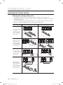
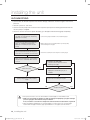
The examples of the refrigerant pipe installation
Heat Pump model
Example of piping layouts for DVM PLUS IV
ENGLISH
Using Y- joint
Using
Header joint
Do not use Y-joint between Header joint and indoor units.
Heat Recovery model
Example of piping layouts
MCU
MCU
MCU
Using Y- joint
MCU
MCU
MCU
installing the unit _27
RD@@@HHXG_IM_E_33140-4.indd 27
2012-01-26 오후 1:14:27
installing the unit
REFRIGERANT PIPING WORKS
Piping examples
Heat Pump model
Branch with Y-joint
One outdoor
unit installed
b
a
h
c
d
e
i
j
k
f
F
l
g
Branch with Header joint
p
G
m
Branch with Y and Header joint
a
n
b
c
d
e
f
g
h
i
Multiple
outdoor units
installed
b
a
h
c
d
e
i
j
k
f
F
l
g
m
p
G
n
Items
Piping
(Equivalent
piping)
Max.
piping
length
Branch with Y-joint
200m below
(220m below)
Outdoor ~
Indoor unit
Branch with Y-joint and
Header joint
Branch with header joint
Branch with Y-joint
Piping
Equivalent
piping
Outdoor ~
Piping
Indoor unit
Indoor ~ Indoor
Piping
unit
Outdoor ~
Piping
Outdoor unit
The first branch
Allowable
~
length after
Piping
the farthest
branch
indoor unit
10m below
13m below
r ≤ 13, s ≤ 13, t ≤ 13m
110m / 40m*2)
H1 ≤ 110m/40m
15m below
H2 ≤ 15m
15m below
H3 ≤ 5m
45m below
b+c+d+e+f+g+p ≤ 45m, i ≤ 45m
90m below *1)
It needs to satisfy required conditions
Distribution kit
From distribution kit to indoor unit
Allowable
From distribution kit to indoor unit
Remarks
a+b+c+d+e+f+g+p ≤ 200m
(220m)
a+i+k ≤ 200m (220m)
a+b+h ≤ 200m (220m)
a+i ≤ 200m (220m)
a+b+c+d+e+f+g+p+h+i+j+k+l+m+n
≤ 1000m
a+b+c+d+e+f+g+p+h+i+j+k ≤
1000m
a+b+c+d+e+f+g+p+h+i ≤
1000m
Branch with Y-joint and
Header joint
Branch with
Header joint
r ≤ 10, s ≤ 10, t ≤ 10m
Total piping 1000m below
Outdoor ~
Outdoor unit
Level
difference
Examples
Model
MEV-A13SA / MEV-A16SA ( For 1 indoor unit)
MXD-A13K116A / MXD-A13K200A / MXD-A16K200A /
MXD-A22K200A ( For 2 indoor units)
20m
MXD-A13K216A / MXD-A13K300A / MXD-A16K213A /
MXD-A16K300A ( For 3 indoor units)
Equivalent pipe
length
Y-joint : 0.5m,
Header : 1m
Only apply to
DVM PLUS IV
(DVM PLUS IV
HR exclusion)
Remarks
3m
For wall-mounted &
ceiling indoor unit
*1) Required condition
Required condition
Example
The first branch joint ~ If the sum of pipe length (b+c+d+e+f+g+p) is over 45m,(but not exceed : 90m)
the farthest indoor unit Increase pipe size of b, c, d, e, f, g. (b, c, d, e, f, g : pipe 1 size up)
If main pipe size is not increased,
a+bx2+cx2+dx2+ex2+fx2+gx2+h+i+j+k+l+m+n+p ≤ 1000m
Total pipe
length size
If main pipe size is increased,
ax2+bx2+cx2+dx2+ex2+fx2+gx2+h+i+j+k+l+m+n+p ≤ 1000m
Each Y-joint ~
h, i, j,...p ≤ 45m
each indoor
The difference between the distance of the outdoor unit to the farthest indoor
Between indoor
unit and the distance of the outdoor unit to the nearest indoor unit ≤ 45m
units
(a+b+c+d+e+f+g+p) - (a+h) ≤ 45m
*2) As an outdoor unit is located in a lower position than indoor unit, level difference is 40m. If outdoor unit is located in a higher position than indoor unit, level difference
is 110m or under. (If the level difference is higher than 50m, make a decision simulating by PDM kit installation Guide software whether the PDM kit should be
installed or not.) *PDM kit: Pressure Drop Modulation kit
The refrigerant amount of the system must be less than 100kg.
28_ installing the unit
RD@@@HHXG_IM_E_33140-4.indd 28
2012-01-26 오후 1:14:28
Heat Recovery model
Branch with Y-joint
Using MCU
only
ENGLISH
MCU
Using Y- joint
and MCU
MCU
Items
Piping
(Equivalent
piping)
Max.
piping
length
Outdoor ~
Outdoor unit
Outdoor ~
Indoor unit
Indoor ~ Indoor
Level
unit
difference
Outdoor ~
Outdoor unit
MCU~MCU
The first branch ~
the farthest
Allowable
length after Indoor unit
branch
MCU(Included
EEV)
Examples
200m below
(220m below)
Total piping 1000m below
Allowable
Using MCU only
Using Y-joint and MCU
a+g+m ≤ 200m (220m)
Using MCU only
a+b+c+d+e+f+g ≤ 1000m
a+b+c+d+e+f+g+p+h+i+j+k+m
≤ 1000m
Using Y-joint and MCU
Piping
Equivalent
piping
10m below
r ≤ 10, s ≤ 10, t ≤ 10m
13m below
r ≤ 13, s ≤ 13, t ≤ 13m
Piping
110m / 40m*2) H1 ≤ 110m/40m
Piping
15m below
H2 ≤ 15m
Piping
5m below
H3 ≤ 5m
Piping
15m below
Piping
45m below
H4 ≤ 15m
Using MCU only
45m
Using Y-joint and MCU
g+m ≤ 45m
Piping
20m below
Distribution kit
From distribution kit to indoor unit
3m
Remarks
a+b+c+d+e+f+g ≤ 200m
(220m)
Equivalent pipe
length.
Y joint : 0.5m,
Header : 1m,
MCU : 1m
m ≤ 20m
Model
Remarks
MEV-A13SA/MEV-A16SA (For 1 indoor unit)
For wall-mounted &
ceiling Indoor unit
*2) As an outdoor unit is located in a lower position than indoor unit, level difference is 40m. If outdoor unit is located in a higher position than indoor
unit, level difference is 110m or under. (If the level difference is higher than 50m, make a decision simulating by PDM kit installation Guide software
whether the PDM kit should be installed or not.) *PDM kit: Pressure Drop Modulation kit
The refrigerant amount of the system must be less than 100kg.
installing the unit _29
RD@@@HHXG_IM_E_33140-4.indd 29
2012-01-26 오후 1:14:29
installing the unit
REFRIGERANT PIPING WORKS
Installing the branch joints
Y-joint
• Install the Y-joint ‘horizontally’ or ‘vertically’.
Install horizontally
Install vertically
Note • When using A~J type of Y-joint, connect the Y-joint to the pipe with provided reducer.
• When using K~Z type of Y-joint, connect the Y-joint to the pipe by cutting the inlet of the
Y-joint or provided reducer properly.
10~15mm
or more
• Keep a minimum distance of 500mm or more before connecting a branch joint.
CAUTION
To other branch
joint or indoor unit
Rear
Reducer
Pipe
Pipe
Reducer
Rear
±15°
Front
To outdoor unit
Install the Y-joint within ±15° on
Main pipe
500mm
or more
the horizontal or on the vertical.
30_ installing the unit
RD@@@HHXG_IM_E_33140-4.indd 30
2012-01-26 오후 1:14:29
Header joint
1. Select the reducer fitted on the diameter of the pipe.
Reducer
Pipe
Reducer
Pipe
Pipe
To indoor unit
To indoor unit
To outdoor unit
To outdoor unit
< Gas side >
2. Braze the pipes ends with caps if the number of connected indoor unit is fewer than header
joint ports.
Connection
in order
Connection
in order
Reducer
< Liquid side >
CAUTION
ENGLISH
< Liquid side >
Blocked the port of
header joint
Blocked the port of
header joint
Reducer
< Gas side >
• W
hen using A~J type of header joint, connect the header joint to
the pipe with provided reducer.
• When using K~Z type of header joint, connect the header joint to
the pipe by cutting the provided reducer properly.
• Connect the header joint in order respecting the number of the indoor unit. • Connect the indoor unit as the highest capacity comes first.
10~15mm
or more
3. Install the header joint horizontally.
- Install the header joint horizontally so that it is not facing down.
Reducer Branch joint
±10°
or less
Should be
horizontal
±15°
or less
< Liquid side >
Note
±15°
or less
Should be
horizontal
Pipe
Should be
horizontal
Should be
horizontal
±10°
or less
Should be
horizontal
< Gas side >
Incorrect installation of Y-joint and header joint cause poor oil and refrigerant distribution
between indoor units.
It may decrease the system’s performance or cause compressor failure.
installing the unit _31
RD@@@HHXG_IM_E_33140-4.indd 31
2012-01-26 오후 1:14:29
installing the unit
REFRIGERANT PIPING WORKS
Installing the branch joints
Outdoor joint
Installation of outdoor joint
Oil balancing
pipe
Gas pipe Liquid pipe
High pressure gas pipe
Do not install the outdoor
joint like the above diagram.
Use the attached reducer properly according to the selected pipe size.
To other outdoor unit
To other outdoor
joint or outdoor unit
Pipe
Reducer
Reducer at the
liquid side
Pipe
To other outdoor joint or
Y-joint of the main pipe
<Liquid pipe>
To other outdoor unit
Pipe
Reducer
To other outdoor
joint or outdoor unit
To other outdoor unit
Reducer
Pipe
To other outdoor joint or
Y- joint of the main pipe
To other outdoor
joint or outdoor unit
<Gas pipe, High pressure gas pipe>
Note • W
hen using A~J type of Outdoor joint, connect the Outdoor joint to the pipe with
provided reducer.
• When using K~Z type of Outdoor joint, connect the Outdoor joint to the pipe by cutting
provided reducer properly.
10~15mm
or more
32_ installing the unit
RD@@@HHXG_IM_E_33140-4.indd 32
2012-01-26 오후 1:14:30
Pipe
To other outdoor unit
To the other
outdoor joint or
outdoor unit
Pipe
Oil balancing
pipe
T-joint (Field supply)
Install the oil balancing pipe without T-joint
To the other outdoor
joint or outdoor unit
when connecting 2 outdoor units.
Note
ENGLISH
<T-joint for oil balancing>
<Oil balancing pipe>
Keep in mind that T-joint must be installed horizontally to have best oil return to each
compressor.
Installing MCU
Model
MCU-Y6NEE
MCU-Y4NEE
MCU-Y4NEE1
Up to 6 units
Up to 4 units
Up to 2 units
Only for large capacity
duct (20.0kW)
44.8kW
44.8kW
44.8kW
The exterior of MCU
Number of connectable
indoor units
The maximum capacity
of the connectable indoor
units
Not included
Cannot connect indoor unit without internal EEV.
Internal EEV
Connecting the pipe
70mm
Protect with
wet towel when
brazing
70mm
Pipe connection from outdoor unit
Low pressure gas pipe connection (Brazing)
High pressure gas pipe connection (Brazing)
Liquid pipe connection (Flare)
Pipe connection to indoor unit
Liquid pipe(Flare)
CAUTION
Gas pipe (Flare)
• U
se the provided installation pattern when installing the MCU.
• Use a welding curtain to prevent the unit to get damaged from a welding fire or flame
when the welding for a high pressure gas pipe & low pressure gas pipe is made.
• Wrap the high pressure gas pipe & low pressure gas pipe with wet cloth when
brazing it.
installing the unit _33
RD@@@HHXG_IM_E_33140-4.indd 33
2012-01-26 오후 1:14:30
installing the unit
WIRING WORK
CAUTION
• Install a circuit breaker. For safety and maintenance, we strongly recommend that
MCCB+ELB or ELCB have to be installed every outdoor unit.
- ELCB : Earth Leakage Circuit Breaker
- MCCB : Molded Case Circuit Breaker
- ELB : Earth Leakage fuse Breaker
• Operate the unit after the refrigerant piping work must be done.
• Do not disassemble or alter the wiring of the unit during the electrical wiring work.
If not, the unit may be damaged.
Specifications of the circuit breaker and power cable
Heat-Pump / Heat-Recovery model
1. SINGLE
Capacity(HP)
Model
MCA
MFA
8
RD080HHXG✴
RD080HRXG✴
RD100HHXG✴
RD100HRXG✴
RD120HHXG✴
RD120HRXG✴
RD140HHXG✴
RD140HRXG✴
RD160HHXG✴
RD160HRXG✴
RD180HHXG✴
RD180HRXG✴
RD200HHXG✴
RD200HRXG✴
23.0
30
26.9
30
35.5
40
36.8
40
47.9
50
53.1
60
55.1
60
10
12
14
16
18
20
2. HIGH EFFICIENCY COMBINATION
Combination
Capacity
(HP) RD080HHXG✴ RD100HHXG✴ RD120HHXG✴ RD140HHXG✴ RD160HHXG✴
RD080HRXG✴ RD100HRXG✴ RD120HRXG✴ RD140HRXG✴ RD160HRXG✴
18
1
20
22
MCA
MFA
1
49.9
50
2
53.8
60
59.8
60
71.0
75
72.3
75
1
84.6
75
1
84.6
75
2
95.8
100
1
1
24
2
26
1
28
1
30
1
1
32
34
1
1
36
2
38
1
1
1
40
2
42
1
44
1
46
48
1
1
97.8
100
101.6
100
1
110.3
100
1
118.9
125
1
120.1
125
2
131.3
125
2
132.5
125
3
143.6
150
34_ installing the unit
RD@@@HHXG_IM_E_33140-4.indd 34
2012-01-26 오후 1:14:30
3. COMPACT COMBINATION
Combination
Capacity
RD080HHXG✴
RD100HHXG✴
RD120HHXG✴
RD140HHXG✴
RD160HHXG✴ RD180HHXG✴ RD200HHXG✴
(HP)
RD080HRXG✴ RD100HRXG✴ RD120HRXG✴ RD140HRXG✴ RD160HRXG✴ RD180HRXG✴ RD200HRXG✴
22
1
1
2
26
1
28
1
30
1
32
1
1
62.4
75.0
71.0
75.0
72.3
75.0
83.4
75.0
88.6
100.0
1
90.6
100.0
1
91.9
100.0
1
103.0
100.0
1
108.3
100.0
2
110.3
100.0
1
1
117.5
125.0
44
2
1
126.1
125.0
46
1
1
127.4
125.0
48
1
1
138.5
125.0
50
1
1
143.8
150.0
52
1
2
145.8
150.0
2
147.0
150.0
2
158.1
150.0
2
163.4
150.0
3
165.4
150.0
34
1
MFA
1
1
36
1
38
1
40
42
1
54
1
1
1
1
56
1
58
1
60
ENGLISH
24
MCA
Note • P
ower supply cords of parts of appliances for outdoor use shall not be lighter polychloroprene
sheathed flexible cord. (Code designation IEC : 60245 IEC66 / CENELEC : H07RN-F)
• Select power supply cord based on MCA.
• MFA is used to select the circuit breaker and the ground fault circuit interrupter (earth leakage
circuit breaker).
• MCA represents maximum input current.
❈Abbreviations
- MCA : Min. Circuit Amps. (A)
- MFA : Max. Fuse Amps. (A)
CAUTION
Safety information for electrical work
• You should install the ELCB or MCCB + ELB
- ELCB(Earth Leakage Circuit Breaker)
- MCCB(Molded Case Circuit Breaker)
- ELB(Earth Leakage fuse Breaker)
• Do not operate the outdoor unit before completing refrigerant pipe work.
• Do not disconnect or change the cable inside the product during the electrical work since it
can cause damage to the product.
• The power supply cable specification is selected according to the condition of air culvert
installation / ambient temperature 30°C/ single multi conductor cables. If the condition is
different from those above consult the installation expert and reselect the power supply cable.
- If the length of power supply cable is longer than 50m, reselect the power supply cable in
light of voltage drop.
• Use incombustible material for the insulator (inner cover)
and sheath (outer cover) for power supply cable.
Insulator
The part
(Inner cover)
• When removing the sheath of the cable, do not use the the core
wire is
Sheath
power supply cable which has scratches on the insulator exposed
(Outer cover)
and the core wire is exposed. When the core wire is
<The example of exposed core wire>
exposed, it can cause fire.
installing the unit _35
RD@@@HHXG_IM_E_33140-4.indd 35
2012-01-26 오후 1:14:31
installing the unit
WIRING WORK
Power supply and communication cable configuration
• Install the main power cable and grounding cable through the knock-out hole that is in the
middle (or in the bottom) of the side of the unit and at the bottom of the front of the unit.
• Install the power and communication cable using the cable tube separately.
• Fix a cable tube using a CD connector(Wire conduit) and bushing at the knock-out hole of the
outdoor unit.
Main unit
Sub unit
Sub unit
or
ELCB MCCB+
ELB
Cable tube
Communication cable
Power∙
Earth cable
High/Low
pressure pipe
Oil balancing pipe
Front side
(Only for module installation)
Earth
Earth
Power Communication
cable among
cable
outdoor units
Earth
Power
cable
Communication cable Power cable
between indoor and
outdoor units
Specifications of the cable tube
Name
Material
CD tube
PVC
Single power cable tube
Galvanized steel sheet
Single vinyl tube for a
power cable
CAUTION
Description
- When the unit is installed indoors
- When the unit is not exposed outdoors because
of concrete construction
- When the unit is installed indoors
- When the unit is exposed outdoors and then the
protection for a power cable is needed
- When the unit is installed indoors
Galvanized steel sheet + - When the unit is exposed outdoors and then
Soft PVC compound
the protection for a power cable or waterproof
function is needed
Caution for knock-out punching
• Make a knock-out hole by driving in a nail.
• After making a knock-out hole, apply rust resisting paint around the hole.
• Remove all burrs at the edge of the knock-out hole and secure the cable to the
outdoor knock-out using lining and bushing with an electrical insulation such as
rubber and so on.
Connect the power cable using the compressed ring terminal.
CAUTION
36_ installing the unit
RD@@@HHXG_IM_E_33140-4.indd 36
2012-01-26 오후 1:14:31
Power wiring diagram
External connection diagram of DVM PLUS IV
3 phase 4 wires
(380-415V~)
3 phase 4 wires
(380-415V~)
3 phase 4 wires
(380-415V~)
MCCB+
ELB
or
ELCB
MCCB+
ELB
or
ELCB
MCCB+
ELB
or
ELCB
Earth
1 phase 220V-240V~
Sub unit 1
Earth
Communication cable
among outdoor units
MCCB+
ELB
or
ELCB
Sub unit 2
Earth
Main unit
Main unit
Sub unit
ENGLISH
Main unit
Sub unit
Communication cable
among outdoor units
Communication cable
(Outdoor unit~Indoor unit)
Earth
Wired remote
controller
Earth
Earth
Communication cable
(Outdoor unit~Indoor unit)
Communication cable
(Outdoor unit~Outdoor unit)
Wired remote Wired remote
controller
controller
• C
onnect the power cable of the outdoor unit after checking that R-S-T-N(3 phase 4 wire) is
properly connected. Even if 380~415V power cable is connected to phase N, PCB and other
components are protected by an electric protection system.
• The communication cable between indoor and outdoor units has no polarity.
• Arrange the cables using cable ties.
❈When you use the 3phase-3wire power supply, contact the local Samsung staff to take extra
steps.
installing the unit _37
RD@@@HHXG_IM_E_33140-4.indd 37
2012-01-26 오후 1:14:31
installing the unit
WIRING WORK
Power wiring diagram
External connection diagram of DVM PLUS IV HR
3 phase 4 wires
Indoor Outdoor
OF1 OF2
Indoor Outdoor
R
S
T
N
OF1 OF2
R
S
T
N
MCU
Earth
Communication
cable between
indoor and outdoor units
Indoor Outdoor
OF1 OF2
Indoor Outdoor
R
S
T
N
OF1 OF2
R
S
T
N
MCU
Earth
Communication
cable between
indoor and outdoor units
CAUTION
• Indoor power supply must be separated from outdoor power supply.
• Connect the communication cable among the outdoor units when combining the
outdoor units.
• Connect the communication cable between indoor and outdoor units to the main
outdoor unit.
• If the communication cable between indoor and outdoor units and the
communication cable among outdoor units are crossed, communication is not
available.
• The length of the cable among the outdoor units should be under 30m or less.
• Do not multiplex the communication cable to prevent communication error.
• Maximum wiring length between the outdoor unit and the farthest indoor unit is
1000 meters.
Communication cable
Communication cable
38_ installing the unit
RD@@@HHXG_IM_E_33140-4.indd 38
2012-01-26 오후 1:14:32
MCU
CASE 1
A
Indoor
unit
B
ELB
MCCB
Indoor
unit
Outdoor
unit
ENGLISH
220-240V~
CASE 2
A
Indoor
unit
Indoor
unit
Indoor
unit
B
ELB
MCCB
220-240V~
Outdoor
unit
• Supply the 220-240V power to L, N of MCU separately from outdoor unit.
• B Connect the communication cable from the outdoor unit to F1, F2 of MCU.
A
Connect the power cable using the compressed ring terminal.
CAUTION
MCU
MCU
Note
Indoor
unit
Indoor
unit
Indoor
unit
Indoor
unit
Indoor
unit
Indoor
unit
MCU
MCU
Indoor
unit
Indoor
unit
Indoor
unit
Indoor
unit
Indoor
unit
Indoor
unit
Communication cables are connected as shown above when installing MCU.
installing the unit _39
RD@@@HHXG_IM_E_33140-4.indd 39
2012-01-26 오후 1:14:33
installing the unit
WIRING WORK
Selecting solderless ring terminal
• S
elect a solderless ring terminal of a connecting power cable based on a nominal dimensions
for cable.
• Cover a solderless ring terminal and a connector part of the power cable and then connect it.
Silver solder
B
D
d1
E
F
L
d2
t
Nominal Nominal dimensions dimensions Standard Standard Standard Standard for cable for screw dimension Allowance dimension Allowance dimension Allowance Min. Min. Max. dimension Allowance Min.
(mm)
(mm)
(mm)
(mm)
(mm2)
(mm)
(mm)
(mm)
(mm)
(mm)
4
9.5
8
15
10
8
15
±0.2
7.1
16
8
16
±0.2
9
8
8
8
8
12
16.5
16
22
50
8
70
8
4/6
25
35
±0.2
5.6
+0.3
-0.2
+0.3
-0.2
+0.3
-0.2
±0.3
11.5
+0.5
-0.2
±0.3
13.3
+0.5
-0.2
22
±0.3
13.5
24
±0.4
17.5
+0.5
-0.2
+0.5
-0.4
3.4
±0.2
5
20
4.3
9
28.5
8.4
6
4.5
±0.2
7.9
9
30
8.4
5.8
±0.2
9.5
13
33
8.4
7.7
±0.2
9.4
±0.2
11.4
±0.3
13.3
±0.4
15
11
13
13
12.5
13
38
43
8.4
8.4
8.4
8.4
17.5 14
50
8.4
18.5 20
51
8.4
34
+ 0.2
0
+0.4
0
+0.4
0
+0.4
0
0.9
1.15
1.45
+0.4
0
1.7
+0.4
0
1.8
+0.4
0
+0.4
0
1.8
2.0
40_ installing the unit
RD@@@HHXG_IM_E_33140-4.indd 40
2012-01-26 오후 1:14:33
Connecting the power terminal
•
•
•
•
onnect the cables to the terminal board using the solderless ring terminal.
C
Connect the certified and rated cables only.
Connect using a driver which is able to apply the rated torque to the screws.
If the terminal is loose, fire may occur caused by arc.
If the terminal is connected too firmly, the terminal may be damaged.
• External force should not be applied to the terminal block and wires.
• The cable ties to fasten the wire should be an incombustible material, V0 or above.
(The cable ties should be used to fasten the power wire and they are supplied with the unit.)
ENGLISH
Solderless
terminal
Cable tie
Thin cable
Thick cable
When connecting two cables to one terminal,
separate the solderless terminal up and down to
prevent it being get loosen. Place the thin
cable upward and the thick cable
downward. Secure the power cable
with the cable tie.
Connector
Tightening Torque (kgf • cm)
12.0~14.7 1 phase 220V
M4
56.1~74.4 3 phase 380V
M8
The place where the sheath of the
power supply cable is removed.
Power supply cable
protective tube
CAUTION
• W
hen removing the outer sheath of the power supply cable, be careful not to scratch
the inner sheath of the cable.
• Make sure that more than 20mm of the outer sheath of the indoor unit power supply
cable and communication cable are inside the electrical component box.
• Install the communication cable separately from power cable and other
communication cables.
Examples to use cable striper
<Cable striper>
1. A
djust the blade position by coin(the controller is at the bottom side of the
tool). Fix the blade position according to the outer sheath thickness of the
power cable.
2. Fix the power cable and tool by using the hook at the top side of the tool.
3. C
ut out the outer sheath of the power cable by revolving the tool in the
direction of the arrow, two or three times.
4. A
t this situation, cut out the outer sheath of the power cable by moving
the tool toward the arrow direction expressed.
5. Slightly bend the wire and pull out the cut part of the outer sheath.
installing the unit _41
RD@@@HHXG_IM_E_33140-4.indd 41
2012-01-26 오후 1:14:34
installing the unit
WIRING WORK
Power supply cable arrangement
3 phase 380V
or
MCCB+
ELB
ELCB
Sub unit
communication cable
Sub unit 3phase 380V
CAUTION
• D
o not let the power supply cable come into contact with the pipes inside the
outdoor unit.
If the power supply cable touches the pipes, the vibration of the compressor is
transferred to the pipes and can damage the power supply cables or pipes, creating
the danger of fire or explosion.
• Make sure that the place where the sheath of power supply cable is removed is
inside the power supply box. If it is impossible, you should connect the protective
tube of power supply cable to the power supply box.
• After positioning the power supply cable into the power supply box, tighten the cover.
Connect the ring terminal of 3phase cable (CV)
Earth
1. Tailor the power cable according to its length and connect it with the solderless terminal.
2. After connecting the power cable to the terminal as seen in the picture, fix it with cable tie.
3. Fix the housing which has an insulator to the terminal board.
42_ installing the unit
RD@@@HHXG_IM_E_33140-4.indd 42
2012-01-26 오후 1:14:34
Ground cable arrangement
• Connect the ground wire to the grounding hole inside the power supply box.
ENGLISH
Earth
Taking wires out of the outdoor unit
Power cable wiring to front side of unit
• C
onnect the cable protection tube into the power supply
box as shown picture.
• Be sure that the power supply cable is not damaged by burr
of knock-out hole.
Power cable wiring to side of unit
• C
onnect the cable protection tube to the power supply box
after knock out the hole in the middle of side cabinet.
• When knocking out the hole, be careful to avoid damaging
to pipes, sensors.
• Be sure that the power supply cable is not damaged by burr
of knock-out hole.
installing the unit _43
RD@@@HHXG_IM_E_33140-4.indd 43
2012-01-26 오후 1:14:35
installing the unit
WIRING WORK
Grounding work
• Grounding must be done by a qualified installer for your safety.
Grounding the power cable
• The standard of grounding may vary according to the rated voltage and installation place of
the air conditioner.
• Ground the power cable according to the following.
Power
condition
Installation
place
High humidity
Average humidity
Low humidity
Perform the grounding
work 2 if possible for your
safety. Note 2)
Voltage of lower than 150V
Perform the
grounding work 3. Note 1)
Voltage of higher than 150V
Must perform the grounding work 3. Note 1)
(In case of installing circuit breaker)
Note 1) Grounding work 3
Grounding must be done by your installation specialist.
Check if the grounding resistance is lower than 100Ω.
When installing a circuit breaker that can cut the electric circuit in case of a short
circuit, the allowable grounding resistance can be 30~500Ω.
Note 2) Grounding at dry place
The grounding resistance is should be lower than 100Ω.
(It should not be higher than 250Ω)
Performing the grounding work
• Use the grounding wire by referring to the specification of the electric cable for the outdoor
unit.
When using the terminal for grounding
only
Grounding terminal
When using grounding of the switch
board
Switch board
44_ installing the unit
RD@@@HHXG_IM_E_33140-4.indd 44
2012-01-26 오후 1:14:35
PERFORMING THE REFRIGERANT GAS LEAK TEST
• Use tools for R410A to prevent the inflow of foreign substances and resist against the internal pressure.
• Do not remove the core of filling port.
• Use dry Nitrogen gas as doing an airtight test like below.
Gauge manifold
Filling port
ENGLISH
Low pressure side
High
pressure
side
Service Valve
Liquid side
pipe
Gas side pipe
Nitrogen gas
Apply pressure to the liquid side pipe, gas
side pipe and oil balancing pipe(only for
module) with Nitrogen gas of 4.1MPa.
If you apply pressure more than 4.1MPa, the pipes may
be damaged.
Apply pressure using pressure regulator.
Keep it for minimum 24 hours to check if
the pressure drops.
After applying Nitrogen gas, check the change of
pressure using pressure regulator.
If the pressure drops, check if there is gas
leak.
If the pressure is changed, apply soapy water to check
the leak. Check the pressure of the gas again.
Maintain 1.0MPa of the pressure before
performing vacuum drying and check
further gas leak.
After checking first gas leak, maintain 1.0MPa to check
further gas leak.
CAUTION
• P
erform a Nitrogen gas leak test the service valve of the outdoor unit closed.
• Charge with nitrogen gas across all three pipe connections.
• If the pipe is filled in a short time with a highly excessive pressure of Nitrogen gas, the
pipes may be damaged. Make sure to use a regulator to prevent the high pressure
Nitrogen gas over 4.1MPa into the pipe.
installing the unit _45
RD@@@HHXG_IM_E_33140-4.indd 45
2012-01-26 오후 1:14:36
installing the unit
VACUUM DRYING
• Use the tools for R410A to prevent the inflow of foreign substances and resist against the internal
pressure.
• Vacuum system to -100.7kPa.
• Use the vacuum pump with the check valve to prevent pump oil from flowing backward while the
vacuum pump is stopped.
• Close the service valve of the liquid side pipe, gas side pipe and oil balancing pipe completely.
Connect the gauge manifold to the liquid
side pipe, gas side pipe and oil balancing
pipe(only for module).
Connect the gauge manifold to the oil balancing pipe.
Perform vacuum drying of the liquid side
pipe, gas side pipe and oil balancing
pipe(only for module) using the vacuum
pump.
Make sure that check is installed valve to prevent pump
oil from flowing into the pipe.
While the vacuum gauge pressure is less
than 5Torr, perform the vacuum drying for
more than 1 hour and then close the valve.
Check the vacuum pressure using the vacuum gauge.
After vacuum pump stops, check whether
the pressure is maintained within 5Torr for
an hour.
More than 5Torr
Check the gas leak again.
- The pressure rises because water is
remaining in the pipe.
Yes
Vacuum destruction
- Apply pressure with Nitrogen gas of
0.05MPa.
No
Adding refrigerant according to piping
length
Perform the vacuuming work again.
No
CAUTION
The pressure rises.
Yes
• If the pressure rises in an hour, water remains inside the pipe or there will be a leak.
• Make sure to perform the airtight test and vacuuming for liquid pipe, gas pipe and high
pressure gas pipe after Heat Recovery installation.
If not, a trouble is caused in the airtight test and vacuum due to obstruction of gas flow.
• When the ambient temperature of vacuuming pipe is low (less than 0°C), moisture might
remain within the pipe. Therefore, pay special attention to the pipe seal in the winter.
46_ installing the unit
RD@@@HHXG_IM_E_33140-4.indd 46
2012-01-26 오후 1:14:36
INSULATING THE REFRIGERANT PIPE
Insulating the refrigerant
• Y
ou must check if there is a gas leak before completing all the installation process.
• Use EPDM insulation which meets the following condition.
Item
Unit
Standard
g/cm3
%
g/cm3
kcal/m·h·˚C
ng/(m²·s·Pa)
g/(m²·24h)
mg/L
%
0.048~0.096
-5 or less
0.005 or less
0.032 or less
15 or less
15 or less
25 or less
ENGLISH
Density
Dimension change route by heat
Water absorption rate
Thermal conductivity
Moisture transpiration factor
Moisture transpiration grade
Formaldehyde dispersion
Oxygen rate
Selecting the insulator of refrigerant pipe
• Insulate the gas pipe and liquid pipe by referring to the thickness of insulator for each pipe size.
• The standard condition is 30°C, less than humidity 85%. If the condition is in high humidity, use
one grade thicker.
Insulator(Cooling, Heating)
Pipe
Pipe size (mm)
Standard
[30°C, 85%]
High humidity
[30 °C, 85% or more]
Remarks
EPDM, NBR
Liquid pipe
Gas pipe
Ø6.35~Ø9.52
Ø12.70~Ø50.80
Ø6.35
Ø9.52~Ø25.40
Ø28.58~Ø44.45
Ø50.80
9t
13t
13t
19t
25t
19t
25t
32t
Heat resisting
temperature is more
than 120°C
38t
• W
hen installing insulation in places and conditions below, use the same insulation that is used
for high humidity conditions.
<Geological condition>
- High humidity places such as shoreline, hot spring, near lake or river, and ridge (when the part
of the building is covered by earth and sand.)
<Operation purpose condition>
- Restaurant ceiling, sauna, swimming pool etc.
<Building construction condition>
- The ceiling frequently exposed to moisture and cooling is not covered.
e.g. The pipe installed at a corridor of a dormitory and studio or near an exit that opens and
closes frequently.
- The place where the pipe is installed is highly humid due to the lack of ventilation system.
installing the unit _47
RD@@@HHXG_IM_E_33140-4.indd 47
2012-01-26 오후 1:14:36
installing the unit
INSULATING THE REFRIGERANT PIPE
Insulating the refrigerant pipe
• Be sure to insulate the refrigerant pipe, joints and connections with class ‘o’ material.
• If you insulate the pipes, the condensed water does not fall from the pipes and the capacity
of the air conditioner is improved.
• Check if there are any insulation cracks on the bent pipe.
Insulation
Gas side pipe
Clamp
Insulation
Liquid side pipe
Indoor
unit
Indoor unit
Install the insulation
to be overlapped
Pipe insulation
Pipe insulation after insulating EEV kit
• Insulation of the gas and liquid pipes can be in contact with • When installing the gas side and liquid side pipes,
each other but they should not be pressing each other.
leave 10mm of space.
• When contacting the gas side and liquid side pipe,
• When contacting the gas side and liquid side pipe,
use thicker insulation.
use thicker insulation.
Insulation
Insulation
10mm
10mm
10mm
Liquid pipe
Gas pipe
CAUTION
• Install the insulation not to be get wider
and use the adhesives on the connection
part of it to prevent moisture entering.
• Wind the refrigerant pipe with insulation
tape if it is exposed to outside sunlight.
• Install the refrigerant pipe respecting that
the insulation does not get thinner on the
bent part or hanger of pipe.
Gas pipe
Liquid pipe
Hanger
Additional
insulation
a
ax3
Insulation for
refrigerant pipe
48_ installing the unit
RD@@@HHXG_IM_E_33140-4.indd 48
2012-01-26 오후 1:14:36
Insulating the branch joint
Y-joint & liquid side of the outdoor unit
• A
ttach the insulation provided with a branch joint to the insulation purchased individually
without a gap. Wrap the connected part with an insulation (purchased in the market) of a
thickness of at least 10mm.
• Use an insulation that should be able to handle the interior temperature over 120°C.
Wrap the branch joint with an insulation of a thickness of at least 10mm.
Pipe insulation
(Field supply)
150mm
Provided
Insulation tape
(Field supply)
Fix securely without any gap.
Pipe insulation
ENGLISH
Fix securely
without any
gap.
Pipe
Branch
joint
Pipe insulation
(Field supply)
A thickness of the insulation (Field supply)
should be at least 10mm.
Pipe insulation
(Field supply)
A
ttach the adhesive insulation tape to
the pipe as shown in the picture after
insulating the pipe.
Header joint
• F
asten the header joint using a cable tie and cover the connected
part.
• Insulate the header joint and the welding part and wrap the connected
part with an adhesive insulation tape to prevent it from defrosting.
Adhesive insulation
tape
Insulation for
the header joint
Insulation for the
refrigerant pipe
Insulation
Insulation after welding a stopper
Adhesive insulation tape
F ix the header joint after insulating it.
installing the unit _49
RD@@@HHXG_IM_E_33140-4.indd 49
2012-01-26 오후 1:14:36
installing the unit
INSULATING THE REFRIGERANT PIPE
Insulating the branch joint
Outdoor joint & gas side of the outdoor unit
• U
se an insulation that should be able to handle the interior temperature over 120°C.
• Wrap the branch joint with an insulation of a thickness of at least 10mm as shown in the
picture.
• Wrap the connected part between the Outdoor joint and the gas side of the outdoor unit
to prevent it from defrosting.
Wrap here with a
vinyl tape
Pipe
Use EPDM insulation.
90°
Pipe insulation
(Purchased individually)
øD
Pipe insulation
(Purchased individually)
Insulation
(Purchased
individually)
Cut the insulation
at the proper angle.
øD
Cut the insulation at the
proper angle.
90°
m
0m
10
re
mo
or
Insulating the interior of the outdoor unit pipe
• Insulate the whole service valve of the outdoor unit with a pipe insulation.
• Seal the gap between the outdoor unit pipe and the insulation.
Rainwater and dewdrops may soak through the gap between the pipe and the insulation
of the outdoor unit installed on the outside.
• Separate the cover of the pipe and close it after insulation work.
Remove a knock-out hole cover that installed the pipe and use it.
If the extra knock-out hole is open, small animals such as squirrels and rats may get into
the unit through the hole and the unit may be damaged.
DVM PLUS IV
DVM PLUS IV HR
50_ installing the unit
RD@@@HHXG_IM_E_33140-4.indd 50
2012-01-26 오후 1:14:37
completing the installation and
commissioning
CHARGING REFRIGERANT
Important information regulation regarding the refrigerant used
ENGLISH
• The R410A refrigerant is blended refrigerant. Add only liquid refrigerant.
• Measure the quantity of the refrigerant according to the length of the liquid side pipe. Add quantity of the
refrigerant using a scale.
This product contains fluorinated greenhouse gases covered by the Kyoto Protocol. Do not vent
gases into the atmosphere.
Inform user if system contains 3kg or more of fluorinated greenhouse gases. In this
case, it has to be checked for leakage at least once every 12 months, according to
regulation n°842/2006. This activity has to be covered by qualified personnel only.
CAUTION
In case situation above (3kg or more of R410A), installer (or recognized person
which has responsibility for final check) has to provide a maintenance book, with
all the information recorded according to REGULATION (EC) N° 842/2006 OF THE
EUROPEAN PARLIAMENT AND OF THE COUNCIL of 17 May 2006 on certain
fluorinated greenhouse gases.
Please fill in with indelible ink,
- the factory refrigerant charge of the product.
- the additional refrigerant amount charged in the field.
-
+ the total refrigerant charge.
The refrigerant charge label supplied with the product.
Note
a
. F
actory refrigerant charge of the product:
see unit name plate.
b. Additional refrigerant amount charged in the field.
(Refer to the above information for the quantity of
refrigerant replenishment.)
c. Total refrigerant charge.
d. Refrigerant cylinder and manifold for charging.
Refrigerant type
GWP value
R410A
1975
GWP=Global Warming Potential
Contains fluorinated greenhouse gases
covered by the Kyoto Protocol.
Indoor unit
d
a
= (
= (
b
CAUTION
) kg
) kg
Outdoor unit
+ = (
) kg
c
he filled-out label must be adhered in the proximity of the product charging port.
T
(ex. onto the inside of the stop valve cover.)
completing the installation and commissioning _51
RD@@@HHXG_IM_E_33140-4.indd 51
2012-01-26 오후 1:14:37
completing the installation and
commissioning
Service valve work for gas pipe
• Block the cap of the service valve after charging the refrigerant.
- Connection torque of the cap for the refrigerant charging port :
6.0N·m
- Connection torque of the stem : 25N·m.
- Adjustable torque of the valve stem.
ø19.05~ : 10.0N·m
Cap for the valve stem
Cap for the refrigerant
charging port
When installing 1 outdoor unit
Outdoor unit
Liquid side
Gas side
R410A
Gauge manifold
Service valve
Scale
Vacuum pump
When installing more than 1 outdoor unit
Outdoor unit
Gauge manifold
Liquid side
Gas side Oil equalization
R410A
Service valve
Scale
Vacuum pump
• O
pen the gauge manifold valve connected to the liquid side service valve and add the liquid
refrigerant.
• If you cannot add the whole quantity of the refrigerant while the outdoor unit is stopped, open
the gas side and liquid side service valve. Add remaining refrigerant by pressing the refrigerant
adding button of the outdoor PCB.
52_ completing the installation and commissioning
RD@@@HHXG_IM_E_33140-4.indd 52
2012-01-26 오후 1:14:37
CAUTION
ENGLISH
• O
pen the gas side and liquid side service valve completely after charging the
refrigerant. (If you operate the air conditioner with the service valve closed, the
important parts may be damaged.)
• When using the modular outdoor unit, open the service valve of the oil balancing
pipe.
• Put on safety equipment when charging refrigerant.
• When the refrigerant is being charged, do not perform any other work such as
insulation, dip switch setting etc.
• Make sure not to get damaged from the fan when operating the unit while the front
panel is being opened.
• Do not heat the refrigerant vessel for fast refrigerant charging when the outside
temperature is low during winter season. There is a potential risk of explosion.
• Make sure that the refrigerant does not emit while connecting the gauge manifold to
the charging port for heating.
• Close the valve of the refrigerant vessel rapidly after charging refrigerant.
If not, a change in the whole refrigerant quantity may occur.
completing the installation and commissioning _53
RD@@@HHXG_IM_E_33140-4.indd 53
2012-01-26 오후 1:14:37
completing the installation and
commissioning
SETTING THE OPTION SWITCHES & FUNCTION KEYS
Option switch of the outdoor unit
Switch
Setting
SW03
SW04
SW05
K5
K9
ON
ON
OFF
OFF
K11
ON
ON
OFF
OFF
K13
ON
ON
OFF
OFF
K15
ON
ON
OFF
OFF
ON
OFF
K10
ON
OFF
ON
OFF
K12
ON
OFF
ON
OFF
K14
ON
OFF
ON
OFF
K16
ON
OFF
ON
OFF
ON
K17
OFF
ON
SW06
K18
OFF
K19
K20
K21
K22
SW07
K23
K24
SW08
Function
Remarks
Setting is available only with the main outdoor unit(sub unit :
setting is unnecessary)
Ex) When the 12 indoor units are installed : [SW01:1, SW02: 2]
Factory default
Setting the total number of indoor unit installation
SW01 : The tens digit, SW02 : The units digit
SW01/
SW02
ON
OFF
ON
OFF
ON
OFF
ON
OFF
ON
OFF
ON
OFF
-
Manual ADDRESS setting
Auto ADDRESS setting
Target evaporating temperature(°C)
7~9
5~7
9~11
10~12
Cooling capacity adjustment
Target high pressure (kg/cm2)
No high pressure target value adjustment
31.5 kg/cm2
25.0 kg/cm2
27.0 kg/cm2
Outdoor unit’s address : No 1
Outdoor unit’s address : No 2
Outdoor unit’s address : No 3
Outdoor unit’s address : No 4
Heating capacity adjustment
Selecting the outdoor units address
Main unit, Factory default
Sub unit 1
Sub unit 2
Sub unit 3
Current limit function
Factory default
Use standard value of current limit
Apply standard value of current limit x 90%
Apply standard value of current limit x 80%
Non use of the standard value of current limit
Standard value (5 hours interval after turning on the outdoor
unit, and then 7 hours interval.)
2 hours interval after turning on the outdoor unit and then 2
hour interval.
Defrosting temperature integer ( ) = MID,
Not using the function to remove snowdrift on the top.
Defrosting temperature integer ( ) = LOW2,
Using the function to remove snowdrift on the top.
Standard value
Fan step compensation (Maximum step)
Standard value
Use night quiet mode
Use anti-dew function mode (in cooling operation)
Non use anti-dew function mode (in cooling operation)
Setting total number of MCU installation
Oil collecting interval
Standard value of defrosting start time
Reduce the defrosting start time
Maximum fan step compensation
Select night’s quiet mode
Select anti-dew function mode
Setting is available only with the main outdoor unit (sub unit : setting is
unnecessary)
When the 12MCU are installed : [SW08:C]
❈ Applicable to HR model only
Factory default setting
SW01/02, SW08 : 0
SW03~07 : On
54_ completing the installation and commissioning
RD@@@HHXG_IM_E_33140-4.indd 54
2012-01-26 오후 1:14:37
Key function
1
2
3
4
5
6
7
8
9
10
11
12
KEY operation
Heating refrigerant charging
Heating trial operation
Heating Pump Out (Outdoor unit address 1)
Heating Pump Out (Outdoor unit address 2)
Heating Pump Out (Outdoor unit address 3)
Heating Pump Out (Outdoor unit address 4)
Vacuum mode (Outdoor unit address 1)
Vacuum mode (Outdoor unit address 2)
Vacuum mode (Outdoor unit address 3)
Vacuum mode (Outdoor unit address 4)
Vacuum mode (All outdoor units)
End KEY operation
K2 (Push time)
1
2
3
4
5
6
KEY operation
Cooling refrigerant charging
Cooling trial operation
Cooling Pump Down (All outdoor units)
Pipe checking
Checking the amount of refrigerant
End KEY operation
K3 (Push time)
1
7-Segment Display
“K” “1” “BLANK” “BLANK”
“K” “2” “BLANK” “BLANK”
“K” “3” “BLANK” “1”
“K” “3” “BLANK” “2”
“K” “3” “BLANK” “3”
“K” “3” “BLANK” “4”
“K” “4” “BLANK” “1”
“K” “4” “BLANK” “2”
“K” “4” “BLANK” “3”
“K” “4” “BLANK” “4”
“K” “4” “BLANK” “A”
-
7-Segment Display
“K” “5”
“K” “6”
“K” “7”
“K” “8”
“K” “9”
KEY operation
Initializing(Reset)operation
K4 (Push time)
ENGLISH
K1 (Push time)
“BLANK”
“BLANK”
“BLANK”
“BLANK”
“BLANK”
“BLANK”
“BLANK”
“BLANK”
“BLANK”
“BLANK”
7-Segment Display
The same as initializing operation
KEY operation
Display
SEG 1
SEG 2, 3, 4
Ex) 16 HP Off, 1, 6
Ex) Loading 13 sec Off, 1, 3
Ex) High pressure 15.2 (kg/cm2) 1, 5, 2
Ex) Low pressure 4.3 (kg/cm2) 0, 4, 3
Ex) 87˚C 0, 8, 7
Ex) 87˚C 0, 8, 7
Ex) 87˚C 0, 8, 7
Ex) 2A 0, 2, 0
Ex) 2A 0, 2, 0
Ex) 2A 0, 2, 0
Ex) -5 ˚C -, 0, 5
Ex) 35˚C 0, 3, 5
Ex) 35˚C 0, 3, 5
Ex) 35˚C 0, 3, 5
Ex) 35˚C 0, 3, 5
Ex) 35˚C 0, 3, 5
Ex) 35˚C 0, 3, 5
Ex) 35˚C 0, 3, 5
Ex) 2000 steps 2, 0, 0
Ex) 2000 steps 2, 0, 0
Ex) 300 steps 3, 0, 0
Ex) 300 steps 3, 0, 0
Ex) 13 steps 0, 1, 3
-42˚C -, 4, 2
-42˚C -, 4, 2
NUL: no result
NG: Failure
80%: or less
120 or more%:
80~120: Display number
Ex) 87˚C 0, 8, 7
Month, day
(ex: 2010. 11. 20 0B20)
1
2
3
4
5
6
7
8
9
10
11
12
13
14
15
16
17
18
19
20
21
22
23
24
25
Outdoor capacity
Digital COMP Loading Time
High pressure (kg/cm2)
Low pressure (kg/cm2)
Discharge temperature COMP1
Discharge temperature COMP2
Discharge temperature COMP3
CT sensor value COMP 1
CT sensor value COMP 2
CT sensor value COMP 3
Suction 1 temperature
Cond Out temperature
Liquid pipe temperature
Oil temperature
Sump temperature COMP 1
Outdoor temperature
EVI inlet temperature
EVI outlet temperature
Main EEV 1 step
Main EEV 2 step
EVI EEV step
HR EEV step
Fan step (SSR or BLDC)
Sump temperature COMP 2
Sump temperature COMP 3
1
2
3
4
5
6
7
8
9
A
B
C
C
C
F
G
H
I
J
K
L
M
N
O
P
26
Result of checking the amount of refrigerant
Q
27
Suction2 temperature
R
28
S/W version
S
completing the installation and commissioning _55
RD@@@HHXG_IM_E_33140-4.indd 55
2012-01-26 오후 1:14:37
completing the installation and
commissioning
SETTING THE OPTION SWITCHES & FUNCTION KEYS
MCU option switch
Indoor unit’s activating switch (ON : Use, OFF : Not use)
�
�� �
����
����
����
Rotary switch for indoor unit address
How to set up
Set the rotary switch located at outdoor
unit PCB to match the number of
connected indoor units (8).
Set the rotary switch located at outdoor
unit PCB to match the number of
connected MCU (2).
When installing more than 2 MCUs, set
each rotary switch of MCU differently.
Set rotary switch located at MCU PCB to
match indoor unit address.
Set the DIP switch of MCU to “OFF”
position for the indoor units that is not
connected.
Key operation
Display MCU
status
Rotary switch for MCU address
MCU PCB
MCU address
Setting the
number of
indoor unit
Setting the
number of
MCU
Outdoor
unit PCB
MCU PCB
MCU address
Indoor unit address
Indoor unit
Indoor unit address
Indoor unit
Display indoor
unit's address
K1
Display Contents
(Pushed time)
1
1
MCU address
1
2
3
MCU EEV step
Subcooler-in EEV step
2
3
4
Subcooler-in sensor temperature
4
5
Subcooler-out sensor temperature
5
Display segment
2
3
Blank
Blank
Blank
Blank
Blank
1
4
Blank
Blank
0
0
0
1
1
4
8
0
1
0
1
4
0
1
2
1
5
0
0
1
0
1
0
Remarks
MCU address 0
MCU address 1
MCU address 2
MCU address 11
MCU address 15
Ex) 1400 steps 140 (Actual steps/10)
Ex) 480 steps
Ex) -1°C
Ex) 10°C
Ex) -1°C
Ex) 10°C
56_ completing the installation and commissioning
RD@@@HHXG_IM_E_33140-4.indd 56
2012-01-26 오후 1:14:38
K1
Display Contents
(Pushed time)
6
7
8
9
10
1
On/Off for solenoid valve A_C, A_H
On/Off for solenoid valve B_C, B_H
On/Off for solenoid valve C_C, C_H
On/Off for solenoid valve D_C, D_H
On/Off for solenoid valve E_C, E_H
On/Off for solenoid valve F_C, F_H
A
B
C
D
E
11
Display segment
2
3
• _C : Cooling solenid valve of port
• _H : Heating solenid valve of port
• 3rd segment : Cooling solenid valve On : 1 / Off : 0
• 4th segment : Heating solenid valve On : 1 / Off : 0
Display contents
-
On/Off for liquid by pass solenoid valve
On/Off for main heating solenoid valve
G
H
Blank
0
0
F
N
F
14
Version
8
A
2
0
15
End of K1 display
Display Contents
1
2
3
4
5
6
7
Indoor unit main address for matching with port A
Indoor unit main address for matching with port B
Indoor unit main address for matching with port C
Indoor unit main address for matching with port D
Indoor unit main address for matching with port E
Indoor unit main address for matching with port F
End of K2 display
1
A
B
C
D
E
F
Display segment
2
3
-
0
0
0
0
1
1
4
0
3
6
9
1
5
On
Off
On
Off
-10
-01
On
Off
Ex) October 20, 2008 8A 20
• 1st segment : Year (ex: 2008 8)
• 2nd segment : Month (1~C)
• 3rd, 4th segment : Day
ENGLISH
12
13
K2
Display
Cooling solenid valve of port B
Heating solenid valve of port B
Cooling solenid valve of port B
Heating solenid valve of port B
F
(Pushed time)
Remarks
4
Remarks
Indoor unit main address of port A : 0
Indoor unit main address of port B : 3
Indoor unit main address of port C : 6
Indoor unit main address of port D : 9
Indoor unit main address of port E : 11
Indoor unit main address of port F : 15
COMPLETING THE INSTALLATION
• Measure the power cable terminal (3-phase: R, S, T, N and 1 phase: L, N) and the grounding of the
outdoor unit using a DC 500V ohm meter before connecting the power.
- The measured value should be over 30㏁.
CAUTION
• N
ever measure the communication terminal to prevent the communication circuit
from being damaged.
• Check the short-circuit of the communication terminal using the circuit test system.
• Check the terminal voltage and the phase using a voltmeter and phase test system before
connecting the power.
- R, S, T, N terminal : 4
00V between wires (R-S, S-T, T-R)
230V between phases (R-N, S-N, T-N)
• Turn the switch on after checking the terminal.
230V
400V
400V
400V
230V 230V
N
T
S
R
<ELB>
• Check the R410A indoor unit is connected.
• If the power cables, R,S and T, are cross wired, E425 error occurs. Check for proper
connection of the power cable.
• Protection system cuts power of the PCB for overvoltage when N phase is cross wired to the
R,S,and T. Check the power connection from N phase if the PCB is not turned on.
completing the installation and commissioning _57
RD@@@HHXG_IM_E_33140-4.indd 57
2012-01-26 오후 1:14:38
completing the installation and
commissioning
COMPLETING THE INSTALLATION
• Check the following after the installation is completed.
• Check the external surface and the inside of the outdoor unit.
• Is there any possibility of short circuit?
Outdoor unit • Is the place well-ventilated and ensures space for service?
• Is the outdoor unit fixed securely?
Installation
Indoor unit
Refrigerant pipe work
• Check the external surface and the inside of the indoor unit.
• Is the place well-ventilated and ensures space for service?
• Check if the center of the indoor unit is ensured and it is installed horizontally.
• Is total number of connecting indoor units in the allowable range?
• Are the length and the difference between the refrigerant pipes within the allowable range?
• Is the Y-joint properly installed?
• Is the pipe properly insulated?
• Is the quantity of the additional refrigerant correctly weighed in?
Installing the drain pipe
• Check the drain pipe of the outdoor unit and the indoor unit.
• Have you completed the drain test?
• Is the drain pipe properly insulated?
Installing the wiring
• Have you performed the earthing work 3 to the outdoor unit?
• Is 2-core cable used?
• Is the length of the wire is in the limited range?
• Is the wiring route correct?
Setting ADDRESS
• Are the ADDRESSES of the indoor and outdoor units properly set?
• Is the switch setting of the indoor units for centralized control properly made?
FINAL CHECKS AND TRIAL OPERATION
Inspection before trial operation
1. Check the power cable and communication cable of the indoor and outdoor unit.
2. Turn the circuit breaker(3 phases and 1 phase) on 4 hours before initial operation so that the
crank case heater can be heated.
3. Check the power supply between the outdoor unit and the cabinet panel.
• Check the 3 phase power of the compressor {L1(Red), L2(White), L3(Black)} by the
3 phase tester.
• Check the 220V power with the voltage meter.
4. Once the outdoor unit is turned on, it performs the tracking to check the connected indoor
unit and options.
5. Write down the details about the installation on the card attached on the front side of the
control box.
CAUTION
• T
urn the circuit breaker on 4 hours before initial operation so the crank case heater
can be heated enough to start the system.
• If the heater is not heated, the air conditioner does not operate for 2 hours and
30 minutes to protect the compressor.
(‘CH’ is displayed on the PCB display of the outdoor unit)
58_ completing the installation and commissioning
RD@@@HHXG_IM_E_33140-4.indd 58
2012-01-26 오후 1:14:38
Trial operation
1. Run the unit by KEY MODE or controller.
• 1st- Operate all indoor units by KEY MODE located outdoor PCB.
2nd- Operate each indoor unit run separately by controller.
• Inspect the compressor sound during the initial operation.
If roaring sound is heard, stop operation.
ENGLISH
• If roaring sound is heard and the pressure does not change, the back-lashing of the
compressor may occur.
Check the power supply of the compressor. If the problem occurs continuously, check
the compressor power cable.
3 phase: T1(L1)(R)-Red, T2(L2)(S)-White, T3(L3)(T)-Black
2. Check the indoor and outdoor units’ running status.
• Check indoor unit cooling and heating air flow
• Each indoor unit controls: air flow direction, air velocity
• Indoor and outdoor unit’s abnormal running noise
• Proper drainage from indoor unit in cooling mode
• Check detail running status using S-NET program.
3. If error occurs during trial operation, check the error code of the unit and follow the
instruction.
4. Explain to the customer how to use the air conditioner according to the user’s manual.
5. Give the installation manual to the user.
CAUTION
Make sure top and bottom cabinets of the outdoor unit are closed before operating.
The unit may not work properly and fail to get S-NET data if the cabinets are open.
completing the installation and commissioning _59
RD@@@HHXG_IM_E_33140-4.indd 59
2012-01-26 오후 1:14:39