1
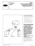
Product
Data
VVT® (Variable Volume and
Temperature) Zoning System
3V™ Control System
The VVT zoning system provides the
following features and benefits:
• New, easy-to-use System Pilot
interface
• Flexible architecture
• Simplified installation and
commissioning
Features/Benefits
The VVT zoning system
provides an effective balance
between flexible zone comfort,
diverse system application
requirements, and efficient
high-performance unit
operation.
User interface
The VVT zoning system is designed to
allow a service person or building owner to configure and operate the VVT
bypass controller and zone controllers,
linkage compatible air source and all
other networked devices through the
System Pilot user interface. The System Pilot’s backlit, alphanumeric Liquid Crystal Display (LCD) and rotary
knob design allow the user to navigate
through the menus, select desired options and modify data with ease. All
VVT zoning system maintenance, configuration, setup and diagnostic information is available through the Level II
communications port to allow data access by the System Pilot or an attached
computer running Network Service
Tool or ComfortVIEWTM software.
Flexibility for every application
The VVT zoning system maintains precise temperature control in the space
by regulating the flow of conditioned
Copyright 2004 Carrier Corporation
Form 33ZC-1PD
air into the space using Carrier’s
VVT® Zone and Bypass Controllers.
Buildings with diverse loading conditions can be supported by controlling
reheat applications, including two-position hot water, modulating hot water,
up to 3-stage electric heat or combination baseboard and ducted heat.
Carrier’s VVT zoning system offers
zone level flexibility with its expanded
range of compatible zone sensors.
Now select the zone level of control required for every application. Carrier’s
sensor offering includes simple space
temperature sensors up to full network
compatible devices.
→ Carrier Linkage System
compatibility
When linked to a Carrier Linkage System, the VVT zoning system components provide numerous features and
benefits such as weighted average demand for system operation, reference
zone temperature and set points, set
point averaging, global set point schedule, and occupancy scheduling.
Additional control features
The VVT zoning system components
provide additional control features such
as Occupied/Unoccupied scheduling
initialized via the network. The VVT
zone controller offers override invoked
from a wall sensor during unoccupied
hours from 1 to 1440 minutes in
→ Ease of installation
1-minute increments. Optional Demand Controlled Ventilation (DCV)
The VVT zoning system components
control or relative humidity monitoring are provided with removable connecare also available.
tors for power, communications, and
damper output. Non-removable screw
Simple actuator connection
type connectors are used for inputs.
The VVT zone controller control asThe VVT zone controller also provides
sembly contains an integral actuator
an RJ-14 modular phone jack for the
assembly that is field mounted to the
Network Service tool connection to the
VVT terminal damper shaft, similar to
module via the Carrier communicating
the mounting of a standard actuator.
network.
The actuator is rated at 35 lb-in.
Table of contents
Features/Benefits . . . . . . . . . . . . . . . . . . . . . . . . . . . . . . . . . . . . . . . . . . 1,2
VVT System Key Components . . . . . . . . . . . . . . . . . . . . . . . . . . . . . . . . 3,4
Dimensions . . . . . . . . . . . . . . . . . . . . . . . . . . . . . . . . . . . . . . . . . . . . . . 5-7
Performance Data . . . . . . . . . . . . . . . . . . . . . . . . . . . . . . . . . . . . . . . . 8-10
Application Data . . . . . . . . . . . . . . . . . . . . . . . . . . . . . . . . . . . . . . . . 11-14
Guide Specifications — 3V Control System . . . . . . . . . . . . . . . . . . . . . 15-22
2
(3.95 N-m) torque, a 45, 60, or
90-degree stroke, and provides
90-second nominal timing at 60 Hz.
The actuator is suitable for mounting
onto a 3/8-in. (9.5 mm) square or
round VVT box damper shaft, or onto
a 1/2-in. (13 mm) round damper shaft.
The minimum VVT box damper shaft
length is 13/4-in. (45 mm). The VVT
zone controller is designed for vertical
or horizontal mounting.
105
VVT® system key components
Terminal control
Bypass controller (33ZCBC-01) — The VVT bypass
controller is a component of Carrier’s 3V™ control system
and is used to regulate the supply duct static pressure for
Variable Volume and Temperature Applications. The
bypass Controller is an essential system component that
allows constant volume HVAC equipment to provide zone
level temperature control.
VVT zone controller (33ZCVVTZC-01) — The VVT
Zone Controller is a component of Carrier’s 3V control
system and is used to provide zone level temperature and
air quality control for Variable Volume and Temperature
Applications. The VVT zone controller is a pressure dependent device that maintains space temperature by modulating the amount of supply airflow through its primary
damper. An integrated 35 in.-lb actuator is standard on all
VVT zone controllers.
VVT zone controllers are available factory mounted to
Carrier’s round and rectangular dampers. Round dampers
are available in 6, 8, 10, 12, 14, and 16-in. sizes. Rectangular dampers are available in 8x10, 8x14, 8x18, and
8x24-in. sizes. All damper assemblies are equipped with an
integrated duct temperature sensor.
Zone controllers are available for field retrofit applications.
VAV zone controller (33ZCVAVTRM, 33ZCFANTRM) —
Carrier’s 3V control system provides seamless integration
of pressure independent zones for use with VVT systems.
Simply use Carrier’s family of VAV zone controllers
(ComfortID™) to regulate the flow of conditioned air into
the space. The VAV zone controllers provide dedicated
control functions for single duct terminals with modulating
heat (up to 2-stages of heat), series fan or parallel fan powered terminals, or as a primary controller for dual duct or
zone pressurization applications. Refer to Carrier’s ComfortID literature for additional information.
Linkage compatible unit controls and auxiliary
controls
Carrier’s 3V control system provides optimized equipment
control through airside linkage. Linkage allows the air
source to adjust its supply air temperature set points and
occupancy schedules to run in the most efficient manner.
The 3V control system linkage compatible controllers
include ComfortLink™, PremierLink™ and the Universal
Controller.
ComfortLink™ controls — The factory-integrated controls are available on Carrier’s 2 to 25 ton Centurion
rooftop product line. The ComfortLink controller is a
component of Carrier’s 3V system and provides: optimum
performance of the rooftop’s refrigeration circuits, an
easy to read English scrolling marquee display and user
interface, and unparalleled diagnostic information with
factory-mounted sensors.
→ PremierLink™ control (33CSPREMLK) — The
PremierLink communicating controller is available as a factory-installed option on 3 to 25 ton rooftop units and as a
field-installed accessory. The control is DCV (Demand
Controlled Ventilation) compatible and internet ready.
3
Universal controller (33UNIVCTRL-01) — The Universal Controller provides auxiliary building control to
interface with lighting, fans, pumps and other HVAC
equipment in a stand-alone or Carrier-networked environment using closed-loop, direct digital controls. The Universal Controller’s pre-engineered algorithms provide simple
building integration for small-to-medium commercial
applications with 16 field point capability (8 inputs and
8 outputs).
→ Interface devices
System Pilot (33PILOT-01) — The System Pilot is a
component of Carrier’s 3V control system and serves as
the user-interface and configuration tool for all Carrier
communicating devices. The System Pilot can be used to
install and commission a 3V zoning system, linkage compatible air source, universal controller and all other devices
operating on the Carrier communicating network.
ComfortVIEW™ software (CEPL130548-01) —
ComfortVIEW software can be installed on a PC and is
used to configure and monitor the 3V system.
Remote
monitoring
capability
device
(33CSCCNWEB-01) — The remote monitoring device
installs on the Carrier network and provides a connection
for a phone line or ethernet connection, allowing the user
to view and change information using a standard web
browser. The user will also have access to the point displays, set point schedules, and operating schedules.
Field-installed accessories
Option board (33ZCOPTBRD-01) — Carrier’s optional relay board may be used with VVT zone controllers to
provide control functions for heat and fan air terminals.
Heating capabilities include modulating heat, up to 3 stages of ducted heat or combination baseboard and ducted
heat control.
Mounting kit — Mounting kits are used to field install the
VVT zone controllers onto Carrier 33CS dampers. Mounting kits come in packages of 10. The 33ZCMBRC-01 kit is
used when mounting on rectangular dampers. The
33ZCMBRD-01 kit is used when mounting on round
dampers.
Sensors
Outdoor-air sensor (HH79NZ039) — The outdoor-air
sensor reads temperatures between 0° and 150 F and is
used to report the outdoor-air temperature to the communication bus. The information can be used to lock out heating or cooling modes when the temperature is not within
user-configured limits. The outdoor-air sensor is needed
when an economizer is used.
Supply air temperature sensor (33ZCSENSAT) —
The supply air temperature sensor is required for heating
applications or stand-alone operation. The sensor has an
operating range of –40 to 245 F (–40 to 118 C) and includes a 6-in. stainless steel probe and cable.
→ Duct temperature sensor (33ZCSENDAT) — The
duct temperature sensor is required for use with a bypass
controller and must be installed in the supply air duct.
105
VVT® system key components (cont)
For bypass systems, the duct temperature sensor should
be moved to a location which will provide the best sensing
of the supply-air temperature during heating and cooling.
For bypass systems, the duct temperature sensor should
be located in the main supply duct downstream of the discharge of the air source and before the bypass damper to
allow good mixing of the supply airstream.
Primary air temperature sensor — The primary air
temperature (PAT) sensor (part number 33ZCSENPAT) is
used on a zone controller which is functioning as a Linkage
Coordinator for a non-communicating or Linkage compatible air source.
Space temperature sensor — A space temperature
(SPT) sensor must be installed for each zone controller.
There are 3 types of SPT sensors available from Carrier:
the 33ZCT55SPT space temperature sensor with
timed override button, the 33ZCT56SPT space temperature sensor with timed override button and set point adjustment, and the 33ZCT59SPT space temperature sensor
with timed push button override button, set point adjustment and digital readout display.
4
The space temperature sensor is used to measure the
building interior temperature and should be located on an
interior building wall.
→ Demand Controlled Ventilation sensor (CO2) — An
indoor air quality sensor is required for optional
Demand Controlled Ventilation. The 33ZCT55CO2 and
33ZCT56CO2 CO2 sensors are indoor, wall-mounted sensors without display.
NOTE: The relative humidity sensor and CO2 sensor cannot be used on the same zone controller.
Humidity sensors — The relative humidity sensor is required for zone humidity control (dehumidification) for
pressure independent zones only. The indoor wallmounted relative humidity sensor (33ZCSENSRH-01) or
duct mounted relative humidity sensor (33ZCSENDRH-01)
can be used.
NOTE: The relative humidity sensor and CO2 sensor cannot be used on the same zone controller.
105
Dimensions
→
BYPASS CONTROLLER
→
VVT ZONE CONTROLLER
(PRESSURE DEPENDENT)
105
5
Dimensions (cont)
→
SYSTEM PILOT
6-in.
(152 mm)
3 1/2-in.
(89 mm)
→
6
PREMIERLINK™ COMMUNICATING CONTROLLER
105
→
RECTANGULAR DAMPERS WITH VVT ZONE CONTROLLER
A
DIMENSIONS (Inches)
PART
NUMBER
33ZCD1008ZC-01
33ZCD1408ZC-01
33ZCD1808ZC-01
33ZCD2408ZC-01
B
D
E
→
C
A
B
C
D
E
101/4
101/4
131/
101/4
101/4
211/4
271/4
8
8
8
8
10
14
18
24
131/2
131/2
131/2
131/2
4
171/4
PART
NUMBER
DUCT SIZE
(in.)
WEIGHT
(lb)
33ZCD1008ZC-01
33ZCD1408ZC-01
33ZCD1808ZC-01
33ZCD2408ZC-01
8 x 10
8 x 14
8 x 18
8 x 24
10.0
11.5
13.0
16.0
CFM AIRFLOW RANGE
Min
Max
410
610
560
825
725
1075
925
1175
ROUND DAMPERS WITH VVT ZONE CONTROLLER
DIMENSIONS (Inches)
PART
NUMBER
33ZCDR06ZC-01
33ZCDR08ZC-01
33ZCDR10ZC-01
33ZCDR12ZC-01
33ZCDR14ZC-01
33ZCDR16ZC-01
B
C
A
B
C
6
8
10
12
14
16
18
18
18
24
24
24
9.0
11.0
13.0
15.0
17.0
19.0
A
PART
NUMBER
33ZCDR06ZC-01
33ZCDR08ZC-01
33ZCDR10ZC-01
33ZCDR12ZC-01
33ZCDR14ZC-01
33ZCDR16ZC-01
105
DUCT
DIAMETER
(in.)
6
8
10
12
14
16
WEIGHT
(lb)
7.0
9.0
10.5
14.0
16.0
17.5
CFM AIRFLOW RANGE
Min
Max
160
280
440
630
850
1125
240
420
660
950
1275
1575
7
Performance data
→
APPLICATION NC* LEVELS (RADIATED SOUND) — ROUND ZONE DAMPERS
DAMPER
CFM
160
200
33ZCDR06ZC-01
240
360
280
350
33ZCDR08ZC-01
420
630
440
514
33ZCDR10ZC-01
584
659
990
630
700
770
33ZCDR12ZC-01
860
950
1425
STATIC PRESSURE
(in. wg)
0.02
0.52
1.00
0.04
0.50
1.00
0.06
0.50
1.00
0.10
0.50
1.00
0.03
0.50
1.00
0.04
0.50
1.00
0.06
0.50
1.00
0.10
0.50
1.00
0.01
0.50
1.00
0.02
0.50
1.00
0.03
0.50
1.00
0.04
0.50
1.00
0.09
0.50
1.00
0.01
0.50
1.00
0.03
0.50
1.00
0.02
0.50
1.00
0.04
0.50
1.00
0.05
0.50
1.00
0.11
0.50
1.00
NC LEVEL
Exceeds recommended NC.
*Noise Criteria.
NOTE: The NC values are based on ARI (Air Conditioning and Refrigeration Institute) Standard 885-90 application assumptions.
8
105
<20
<20
25
<20
22
24
<20
24
28
28
32
35
<20
<20
22
<20
22
22
25
25
27
28
28
30
22
25
27
22
28
29
25
27
32
30
32
34
35
35
37
22
35
38
22
37
38
22
38
39
27
39
40
32
40
40
40
44
45
→
APPLICATION NC* LEVELS (RADIATED SOUND) — ROUND ZONE DAMPERS (cont)
DAMPER
CFM
852
976
1074
33ZCDR14ZC-01
1175
1275
1910
1125
1175
1275
1376
33ZCDR16ZC-01
1475
1574
1676
2512
STATIC PRESSURE
(in. wg)
0.02
0.50
1.00
0.01
0.50
1.00
0.01
0.50
1.00
0.01
0.50
1.00
0.06
0.50
1.00
0.13
0.50
1.00
0.02
0.50
1.00
0.04
0.50
1.00
0.05
0.50
1.00
0.05
0.50
1.00
0.06
0.50
1.00
0.07
0.50
1.00
0.03
0.50
1.00
0.18
0.50
1.00
NC LEVEL
22
30
35
25
32
36
30
32
27
30
35
38
30
36
39
41
45
47
27
39
41
30
39
41
31
40
42
35
41
44
35
42
45
36
44
46
38
45
46
50
51
54
Exceeds recommended NC.
*Noise Criteria.
NOTE: The NC values are based on ARI (Air Conditioning and Refrigeration Institute) Standard 885-90 application assumptions.
105
9
Performance data (cont)
→
APPLICATION NC* LEVELS (RADIATED SOUND) — RECTANGULAR ZONE DAMPERS
DAMPER
CFM
410
509
33ZCD1008ZC-01
610
914
561
625
33ZCD1408ZC-01
725
825
1237
725
775
874
33ZCD1808ZC-01
974
1075
1611
925
974
1075
33ZCD2408ZC-01
1175
1275
1375
2062
STATIC PRESSURE
(in. wg)
0.01
0.50
1.00
0.03
0.50
1.00
0.07
0.50
1.00
0.16
0.50
1.00
0.02
0.50
1.00
0.02
0.50
1.00
0.03
0.50
1.00
0.05
0.50
1.00
0.11
0.50
1.00
0.01
0.50
1.00
0.01
0.50
1.00
0.02
0.50
1.00
0.02
0.50
1.00
0.03
0.50
1.00
0.06
0.50
1.00
0.01
0.50
1.00
0.01
0.50
1.00
0.01
0.50
1.00
0.02
0.50
1.00
0.02
0.50
1.00
0.03
0.50
1.00
0.06
0.50
1.00
NC LEVEL
Exceeds recommended NC.
*Noise Criteria.
NOTE: The NC values are based on ARI (Air Conditioning and Refrigeration Institute) Standard 885-90 application assumptions.
10
105
<20
30
45
<20
30
40
23
31
40
35
37
45
<20
36
47
22
37
45
25
38
45
32
40
46
40
45
54
22
38
48
22
38
48
28
40
48
30
42
48
33
44
50
40
50
60
26
38
48
27
38
50
32
40
50
35
41
50
37
43
50
38
44
50
47
50
55
Application data
Typical VVT® system overview
dependant system that adjusts damper position based on
space temperature variation from set point.
Typical VVT applications include medical and dental
offices, 1 to 3 story commercial buildings, and strip mall
and retail stores.
The VVT system is a control system designed to provide
multiple zones of temperature control using a single,
constant volume heating and cooling packaged unit. Traditionally, the VVT system has been primarily a pressure
→
VVT PRESSURE DEPENDENT SYSTEM
Supply Air
Sensor
Carrier Communicating RTU
(Use PremierLink Retrofit Control for non Carrier communicating RTU)
Communication Bus
20/3/Shielded cable
(See Notes 1,2)
120 vac
(See Note 2)
24vac
40va
24vac
40va
Bypass
VVT Linkage
Coordinator
(See Note 3)
Comm Bus
—
—
—
—
—
24vac
40va
(See Note 5)
20/2/Shielded cable
(See Note 2)
CCN
DCV
PAT
RTU
VVT
24vac
40va
Primary Air
Sensor
Duct Sensor
(Located in main supply duct)
System Pilot
(See Note 6)
24vac
40va
VVT Zone
20/3/Shielded Cable
(See Note 2)
(Optional
for Linkage
Coordinator)
T55/56
LEGEND
Carrier Comfort Network
Demand Controlled Ventilation
Primary Air Temperature Sensor
Rooftop Unit
Variable Volume and Temperature
VVT Zone
Comm Bus
32 zones max
including Linkage
Coordinator
T55/56
T55/56
CO2/T55/56
(Optional for DCV)
See Note 2,4)
NOTES:
1. 239 devices maximum per bus. Repeater required every 1000 ft or 60 devices. Maximum of 3 repeaters per bus.
2. Communication bus and sensor wiring MUST be separate from AC power wiring.
3. Up to 32 total zones per system. Maximum of 8 Linkage Coordinators with a total of 128 devices per single bus.
4. Combination CO2/T55/T56 sensor may be used in place of T55/T56/T59 on any zone requiring DCV. RTU must be capable of controlling
economizer for DCV conditions.
5. Locate PAT in supply air duct from air source unit.
6. System Pilot can share power with Bypass Controller or VVT Zone Controller.
TYPICAL VVT SYSTEM
PRESSURE DEPENDENT CONTROL ONLY
REQUIRED COMPONENTS
Part Number
Usage
1
per
pressure
VVT Zone Controller
33ZCVVTZC-01 dependent zone
Devices
Bypass Controller
Devices
PremierLink™
Controller
Supply Air
Temp Sensor
33ZCBC-01
1 per system
System Pilot
33PILOT-01
1 per system on com bus.
Optional for space sensors
Space Sensor
33ZCT55SPT
33ZCT56SPT
33ZCT59SPT
1 per zone
Relative Humidity
Sensor
Primary Air Temp Sensor
33ZCSENPAT
1 per Linkage
Coordinator
Outside Air Temp
Sensor
CO2 Sensors
OPTIONAL COMPONENTS
Part Number
Usage
1
required
per
if non33CSPREMLK communicatingsystem
air source.
1 required for bypass
33ZCSENSAT
Option for zones
33ZCT55CO2
as required per zone for DCV
33ZCT56CO2
33ZCSENSRH-01 Optional to Monitor RH
33ZCSENDRH-01 only (if no DCV sensor).
HH79NZ039
Required with field-installed
PremierLink control
LEGEND
DCV — Demand Controlled Ventilation
RH — Relative Humidity
105
11
Application data (cont)
VVT® pressure dependent and independent
system overview
control system both forms of control are available. Simply
use Carrier’s VAV Zone Controller, to provide pressure independent control for critical airflow zones.
In many applications VVT Systems require both pressure
dependent and independent zone control. With 3V™
→
VVT PRESSURE DEPENDENT AND INDEPENDENT SYSTEM
Carrier Communicating RTU
Supply Air
Sensor
(Use PremierLink Retrofit Control for non Carrier communicating RTU)
120 vac
Communication Bus
20/3/Shielded cable
(See Notes 1,2)
(See Note 2)
24vac
40va
24vac
40va
VVT Linkage
Coordinator
(See Note 3)
Bypass
VVT Zone
Comm Bus
LEGEND
ComfortID Zone
20/3/Shielded cable
(See Note 2)
(Optional for Linkage
Coordinator)
—
—
—
—
—
24vac
40va
(See Note 5)
20/2/Shielded cable
(See Note 2)
CCN
DCV
PAT
RTU
VVT
24vac
40va
Primary Air
Sensor
Duct Sensor
(Located in main supply duct)
System Pilot
(See Note 6)
24vac
40va
T55/56
T55/56
Comm Bus
32 zones max
including Linkage
Coordinator
T55/56
CO2/T55/56
(Optional for DCV)
See Note 2,4)
Carrier Comfort Network
Demand Controlled Ventilation
Primary Air Temperature Sensor
Rooftop Unit
Variable Volume and Temperature
NOTES:
1. 239 devices maximum per bus. Repeater required every 1000 ft or 60 devices. Maximum of 3 repeaters per bus.
2. Communication bus and sensor wiring MUST be separate from AC power wiring.
3. Up to 32 total zones per system. Maximum of 8 Linkage Coordinators with a total of 128 devices per single bus.
4. Combination CO2/T55/T56 sensor may be used in place of T55/T56/T59 on any zone requiring DCV. RTU must be capable of controlling
economizer for DCV conditions.
5. Locate PAT in supply air duct from air source unit.
6. System Pilot can share power with Bypass Controller or VVT Zone Controller.
VVT PRESSURE DEPENDENT AND INDEPENDENT SYSTEM
Devices
REQUIRED COMPONENTS
Part Number
VVT Zone Controller
Usage
33ZCVVTZC-01 1 per pressure
dependent zone
1 per pressure
independent zone
OPTIONAL COMPONENTS
Part Number
Usage
1
required
per
system if
PremierLink™
33CSPREMLK
non-communicating air
Controller
source.
1 required for bypass
Supply Air Temp Sensor
33ZCSENSAT
Option for zones
33ZCT55CO2
as required per zone for
CO2 Sensors
33ZCT56CO2
DCV
Devices
VAV Zone Controller
(ComfortID)
33ZCVAVTRM
Bypass Controller
33ZCBC-01
1 per system
System Pilot
33PILOT-01
1 per system on
com bus.
Optional for space
sensors
Relative Humidity Sensor
Space Sensor
33ZCT55SPT
33ZCT56SPT
33ZCT59SPT
1 per zone
Outside Air Temp Sensor
Primary Air Temp Sensor
33ZCSENPAT
1 per Linkage
Coordinator
LEGEND
DCV — Demand Controlled Ventilation
12
105
33ZCSENSRH-01 Optional to Monitor RH only
33ZCSENDRH-01 (if no DCV sensor).
HH79NZ039
Required with field-installed
PremierLink control
Fan powered and reheat VVT® system overview
and your system is ready. New reheat flexibility offers
floating-point control for hot water valves and combination
2-position baseboard with ducted staged heat.
Adding supplemental heat and fan-powered terminals has
never been simpler than with 3V™ control system. Simply
add a stackable option board to any VVT zone controller
→
VVT PRESSURE DEPENDENT/PRESSURE INDEPENDENT WITH
FAN POWERED ZONES AND/OR REHEAT SYSTEM
Carrier Communicating RTU
Supply Air
Sensor
(Use PremierLink Retrofit Control for non Carrier communicating RTU)
Communication Bus
20/3/Shielded cable
(See Notes 1,2)
120 vac
24vac
(See Note 2)
40va
Duct Sensor
(Located in main supply duct)
Supply Air
Sensor
(See Note 6)
20/2/Shielded cable
(See Note 2)
24vac
40va
Primary Air
Sensor
24vac
40va
24vac
40va
24vac
40va
(See Note 5)
H
Pipe Sensor
12
C
Opt
Brd
Opt
Brd
System Pilot
(See Note 8)
Bypass
Comm Bus
CCN
DCV
PAT
RTU
VVT
—
—
—
—
—
LEGEND
Carrier Comfort Network
Demand Controlled Ventilation
Primary Air Temperature Sensor
Rooftop Unit
Variable Volume and Temperature
VVT Linkage
Coordinator w/
Modulating HW
(See Note 3,7)
ComfortID Zone
w/Series FP and
2 Stage Electric Heat
(See Note 7)
VVT Zone w/2
Position HW
Baseboard Heat
(See Note 7)
(Optional
for Linkage
Coordinator)
Comm Bus
20/3/Shielded Cable
(See Note 2)
T55/56
T55/56
32 zones max
including Linkage
Coordinator
T55/56
CO2/T55/56
(Optional for DCV)
See Note 2,4)
NOTES:
1. 239 devices maximum per bus. Repeater required every 1000 ft or 60 devices. Maximum of 3 repeaters per bus.
2. Communication bus and sensor wiring MUST be separate from AC power wiring.
3. Up to 32 total zones per system. Maximum of 8 Linkage Coordinators with a total of 128 devices per single bus.
4. Combination CO2/T55/T56 sensor may be used in place of T55/T56/T59 on any zone requiring DCV. RTU must be capable of controlling
economizer for DCV conditions.
5. Locate PAT in supply air duct from air source unit.
6. Locate downstream of ducted reheat.
7. Option Board required for all VVT zones with heat and/or fan powered mixing box.
8. System Pilot can share power with Bypass Controller or VVT Zone Controller.
FAN POWERED AND REHEAT VVT SYSTEMS
PRESSURE DEPENDENT AND INDEPENDENT CONTROL CAPABILITY
REQUIRED COMPONENTS
Part Number
Usage
1
per
pressure
VVT Zone Controller
33ZCVVTZC-01 dependent zone
1 per pressure
VAV Zone Controller
33ZCFANTRM independent zone
(ComfortID)
with fan or reheat
Devices
Devices
PremierLink™
Controller
Supply Air
Temp Sensor
33ZCSENSAT
1 required for bypass
Option for zones
33ZCT55CO2
as required per zone for DCV
33ZCT56CO2
Relative Humidity 33ZCSENSRH-01 Optional to Monitor RH only
Sensor
33ZCSENDRH-01 (if no DCV sensor).
CO2 Sensors
Bypass Controller
33ZCBC-01
1 per system
System Pilot
33PILOT-01
1 per system on com bus.
Optional for space sensors
Space Sensor
33ZCT55SPT
33ZCT56SPT
33ZCT59SPT
1 per zone
1 per Linkage
Coordinator
1 required per
Fan/Reheat Option Board 33ZCOPTBRD-01 VVT Zone
with Reheat
Primary Air Temp Sensor
OPTIONAL COMPONENTS
Part Number
Usage
1
required
per
system
if non33CSPREMLK
communicating air source.
33ZCSENPAT
Strap-on Pipe
Temp Sensor
33ZCSENCHG
Outside Air
Temp Sensor
HH79NZ039
Optional if baseboard heat ONLY.
(Not required with zone ducted heat)
Required with field-installed
PremierLink control
LEGEND
DCV — Demand Controlled Ventilation
PD — Pressure Dependent
RH — Relative Humidity
105
13
Application data (cont)
Compatibility of Carrier systems
The following chart shows the compatibility of Carrier’s
3V™ Control System and GEN-III VVT® products.
VVT Gen II conversion (manufactured prior to July
1995) — There is no compatibility between VVT Gen II
systems and 3V control systems. A complete change of
system components is required with the exception of
physical dampers which may remain in place. The existing
5-wire control wiring from the thermostat to the damper
may be used for the System Pilot communication wire or
for a T55, T56, or T59 space sensor. The wiring must be
18 to 20 AWG (American Wire Gage) stranded, shielded
cable and conform to 3V control system and Carrier communicating network wiring guidelines. Any wiring that
does not conform to these guidelines must be replaced.
3V AND GEN-III VVT PRODUCT COMPATIBILITY CHART
GEN III PRODUCT
→
DESCRIPTION
COMPATIBLE FOR USE
WITH 3V CONTROL SYSTEM
TEMP SYSTEMS
Working Gen-III TEMP systems may reside on same bus with a 3V control system. If an existing Gen-III TEMP system needs component replacement,
refer to the components below.
33CSTM(T)-01
TEMP Monitor
No. Replace with PremierLink™ control
33CSUCE-06
TEMP System Relay Pack
No. Replace with PremierLink control
VVT GEN-III SYSTEM COMPONENTS
Working Gen-III VVT systems may reside on same bus with a 3V control system. If an existing Gen-III system needs component replacement,
refer to the components below.
33CSVM(T)-32
VVT Monitor Thermostats
Yes for a 3V Zone(s)*
33CSBC-00
Bypass Controllers
Yes. †
33CSZC-01
Pressure Dependent Zone Controller
No. Use 33ZCVVTZC-01.**
33CSZC-PI
Pressure Independent Zone Controller
No. Use 33ZCVAVTRM-01.††
DAMPERS
33CSDCDR
Round or Rectangular
Yes – sheet metal only
33CASDCARPL, M08
Damper Actuators
No
33CSDCA060,090
High Torque Damper Actuators
No
RELAY PACKS
33CSZRP-06
Universal Damper Relay Pack
No
33CSUCE-06
Monitor-only Relay Pack
No
SENSORS
920238 (HS)
Humidity Sensor
No, 3V system uses 2 to 10 vdc humidity sensor.
920247 (RAS)
Refrigerated Air (DX) Sensor
No. 3V system uses standard 10K sensors.
920076 (RDS)
Remote Duct Sensor
No. 3V system uses standard 10K sensors.
920077 (RDS)
Remote Room Sensor
No. 3V system uses standard 10K sensors.
920089 (OAS)
Outside Air Sensor
No. 3V system uses standard 10K sensors.
Pressure Sensor
No, 3V static pressure sensor is integrated into Bypass
33CSPS-01
Controller. For PI zones, velocity pressure sensor is
integrated into the VAV (ComfortID™) controller.
Pressure Sensor
No, 3V static pressure sensor is integrated into Bypass
33CSPS-02
Controller. For PI zones, velocity pressure sensor is
integrated into the VAV (ComfortID) controller.
Yes — vdc type
33ZCSENCO2
CO2 Sensor
EXISTING WIRING
Non-Shielded device, bus or sensor wiring
No
Shielded device, bus or sensor wiring
Yes
24 VAC power wiring
Yes
LEGEND
DX — Direct Expansion
PI
— Pressure Independent
VVT — Variable Volume/Variable Temperature
*A Gen-III VVT Monitor will scan new 3V zones. No special configuration is
required. Address 3V zone within the Gen-III Monitor’s scanning range. If
the Gen-III VVT monitor needs replacement and components are not
available, 3V zone controller(s) may be substituted for all zones with compatible sensors. Existing damper may be re-used, but with new 3V actuator(s).
†An Integrated Gen-III Bypass Controller and damper may remain in 3V
system, but must be re-addressed out of the 3V system’s scanning range,
and must be configured for Standalone operation. If the Gen-III Bypass
14
105
Controller needs replacement and components are not available, 3V
bypass controller may be substituted with compatible sensors. Existing
damper may be re-used, but with new 3V actuator.
**A Gen-III Pressure Dependent Zone Controller is not compatible in 3V
system. However, a 3V zone controller is compatible in a Gen-III system.
If the Gen-III Zone Controller needs replacement and components are not
available, 3V zone controller may be substituted with compatible sensors.
Existing damper may be re-used, but with new 3V actuator.
††A Gen-III Pressure Independent Zone Controller is not compatible with 3V
systems. If the Gen-III PI Zone Controller needs replacement and components are not available, ComfortID controller may be substituted when
configured for Standalone only out of Gen-III Monitors scanning range,
and with compatible sensors. Existing damper may be re-used, but with
new ComfortID actuator.
Guide specifications — 3V™ control system
Variable Volume/Variable Temperature (VVT®)
Multiple Zone HVAC Control System
Model Number:
33ZCVVTZC-01 Zone Controller
33ZCBC-01 Bypass Controller
33PILOT-01 System Pilot
Part 1 — General
1.01 SYSTEM DESCRIPTION
The 3V™ control system shall consist of programmable, multiple communicating Zone Controllers;
and a Bypass Controller. The system shall also
include a complete array of input and output
devices. The system shall provide full control of
HVAC heating and cooling equipment in a multiple
zone application. The 3V system shall be capable of
operating as a stand-alone system or networked with
multiple systems connected on a communications
bus to communicating air source controllers.
1.02 DELIVERY, STORAGE AND HANDLING
The products shall be stored and handled per manufacturer’s recommendations.
Part 2 — Products
2.01 EQUIPMENT
A. General:
The control system shall be available as a complete
package with the required input sensors and devices
readily available. The system shall be capable of providing complete control of HVAC functions; variable
air zone control, bypass air control in both pressure
dependent and pressure independent applications.
Airside controls shall be capable of operating 3V system dampers as well as VAV (variable air volume) terminal boxes and Fan Powered terminal boxes with
and without supplemental heat sources at the zone.
All temperature sensors shall be capable of being read
and displayed in 0.1° F increments. Controllers shall
support either a local dedicated or remote System
Pilot capable of displaying sensor and input information applicable to the controller in degrees Fahrenheit
or Celsius. The System Pilot shall be capable of displaying the following information as a minimum:
System Pilot Linkage Coordinator Zone Controller Display:
1. Space Temperature
2. Primary Air Temperature
3. Damper Position Desired
4. Damper Position Actual
5. Cfm (Pressure Independent Controllers Only)
6. Average Temperature from multiple remote
Room Sensor(s)
7. Zone Indoor Relative Humidity
8. Zone Indoor CO2 concentration
9. Zone Supply Air Temperature
10. Outside Air Temperature
11. Air Source Mode
System Pilot Zone Controller Display:
1. Space Temperature
2. Damper Position Desired
3. Damper Position Actual
4. Cfm (Pressure Independent Controllers Only)
5. Average Temperature from multiple remote
Room Sensor(s)
6. Zone Indoor Relative Humidity
7. Zone Indoor CO2 concentration
8. Zone Supply Air Temperature
9. Outside Air Temperature
10. Air Source Mode
System Pilot Bypass Controller Display:
1. System Pressure in hundredths of an inch
2. System Pressure Set Point
3. Damper Position Desired
4. Damper Position Actual
5. Air Source Supply Air Temperature
6. Air Source Mode
7. All applicable sensors shall be accessed for calibration at the controller display.
B. Rooftop Controller Interface:
The VVT zone controller shall be capable of zone
demand data coordination with a communicating
rooftop. Set point and temperature information
from the zones shall be shared with the rooftop controller so that the rooftop controllers error reduction
calculations can determine the proper number of
heating or cooling stages to operate in order to balance the system load.
C. Memory and Timeclock:
The system shall not require the use of batteries for
any data storage. The VVT zone controller and
Bypass Controller shall have a Non-Volatile Memory
providing indefinite storage of configuration data.
The VVT zone controller shall have a 365-day software clock with built in daylight savings time and
leap year adjustment. In the event of power failure,
the timeclock may be automatically updated with
current time and date from a network Time Sync
device. The network time sync device shall update
all software and Hardware clocks on the communications network twice a day. The System Pilot shall
be capable of sharing time information with other
3V system controls or any other General Purpose
Electronic Controller existing on the communications bus with timeclock capabilities. The VVT zone
controller shall also have the capability of changing
occupancy mode by reading a set of discrete, dry
contacts controlled by an external timeclock.
D. Set Points:
1. The VVT zone controller shall utilize and store
the following set points:
a. Occupied Heating Set Point
15
Guide specifications — 3V™ control system
(cont)
b. Occupied Cooling Set Point
c. Unoccupied Heating Set Point
d. Unoccupied Cooling Set Point
e. Ventilation CO2 Set Point
2. The Linkage Coordinator shall utilize and store
these additional set points:
a. Space Temperature Occupied Hysteresis
b. Unoccupied Space Temperature Low Limit
c. Unoccupied Space temperature High Limit
d. Heating OAT Lockout Set Point
e. Cooling OAT Lockout Set Point
3. VAV Zone Controllers with the pressure independent control feature shall utilize and store
these additional set points:
a. Heat Minimum Airflow Set Point
b. Heat Maximum Airflow Set Point
c. Cool Minimum Airflow Set Point
d. Cool Maximum Airflow Set Point
e. Reheat Airflow Set Point
4. Bypass Controllers shall utilize and store these
set points:
a. System Pressure Set Point
b. Heat Leaving Air Temperature Limit
c. Cool Leaving Air Temperature Limit
d. Leaving Air Temperature Pressure Delta
5. All set points shall be capable of being modified
at the controller display or through a communication network with a System Pilot or PC and
EMS (Energy Management System) software.
E. Scheduling:
The system shall be capable of operating in an occupied or unoccupied mode with up to 8 period
changes per day including holidays. All 3V™ zone
controllers shall have the capability to follow independent local schedules or receive the schedule from
other Application specific controllers as well as all
General Purpose Electronic Controllers (GPECs)
existing on the communications bus with scheduling
capabilities. All schedules shall be adjustable in oneminute increments.
The VVT® zone controller shall be capable of utilizing up to 16 holiday schedules with up to 99 days
per schedule for overriding the occupancy schedule.
The VVT zone controller shall have built-in override
capabilities for unoccupied schedule override from 0
to 24 hours in 1-minute increments. Schedule overrides and schedules shall be flexible enough to allow
individual zones to become occupied without the
rest of the system becoming occupied or allow some
or all zones of an associated piece of equipment, or
from several pieces of equipment to become occupied together. When scheduled to become occupied
together, all zones from that group should participate in a single occupancy override from any single
16
F.
G.
H.
I.
request. When scheduled to operate independently
only the zone where the Occupancy override was
requested should become occupied.
Security Level:
The System Pilot(s) shall have four levels of security
for access of control tasks and decisions with level
one providing full access and level four providing
read access only from the controller. Levels two and
three provide limited access.
HVAC Equipment Protection:
The air sources controller shall be capable of monitoring the leaving air temperature to control stages
in both the heating and cooling modes. It shall have
the capability to shut down stages based on a rise or
fall in leaving air temperature above or below adjustable or calculated values. Calculated supply air temperature requirements shall be based on error
reduction calculations from reference zone data to
determine the optimum supply air temperature to
satisfy space requirements. The system and shall
provide protection from short cycling of heating and
cooling by utilizing time guards and minimum run
time configurations.
Sensor Calibration:
All applicable sensors shall be accessed for calibration at the controller or through a communicating
network with a System Pilot device or PC and EMS
software.
Energy Conservation:
The system shall incorporate the following features
for the provision of energy conservation:
1. Load balancing from error reduction calculations that optimize staging.
2. The locking out of mechanical heating or cooling modes based on configurable outside air
temperature limits.
3. The system shall intelligently start all equipment
in a stagger start manner after a transition from
unoccupied to occupied modes as well as power
failure to reduce high peak power consumption
on start-up.
4. 3V controllers shall have the capability of being
overridden by a Peak Demand Limiting Option
Module existing on the communications bus
with demand limiting functions to reduce overall
energy consumption and control on and off
peak time kW usage.
5. Temperature compensated start. The zone controller shall be capable of supporting temperature compensated start with the air source.
Prior to occupancy the zone controllers and Air
Source shall work together to provide zone-byzone temperature compensated conditioning.
The air source will track the time required for
recovery report the optimal start bias time to
the zones prior to each occupied period so that
the zone can start conditioning the space prior
to occupancy.
J. Stand-Alone Capability:
The controllers shall be capable of providing all control functions of the HVAC system without the use
of a computer. All configuration selections shall be
capable of being performed at a System Pilot display via push button access.
The controllers shall include the inherent capability
to access the system control selections as well as
to monitor system performance by means of a communicating network with a PC and EMS software
program.
K. DDC Control Networking:
The 3V™ system controllers shall be capable of
sharing the same communication network as
General Purpose Electronic Modules and option
modules.
The System Pilot shall be capable of broadcasting
time and date. The air source controller shall be
capable of broadcasting outside air temperature,
outside air enthalpy status, or outside air CO2 concentration on the communications bus to other
Application Specific Controllers, and General Purpose Electronic Controllers existing on the network.
The VVT® zone controllers shall also be able to
receive this information and more from the same
type of controllers on the network communications
bus.
The VVT zone controllers shall also be capable of
receiving commands from General Purpose Electronic Controllers (GPEC) existing on the communications bus. This information shall be used in a
variety of ways to control the HVAC system as well
as other building functions and applications.
L. VVT Zone Controller as a Linkage Coordinator:
1. The VVT zone controller shall be capable of
controlling space demand in a variable volume
application by monitoring space temperature
and determining the heating or cooling
demand. The space temperatures shall be controlled to maintain individual heating and cooling setpoints. The VVT zone controller shall
have the capability of scanning up to 32 linked
zones including itself and determining system
heating and cooling requirements. Individual
zones may be configured so that they do not
participate in system mode determination for
heating and cooling or just for the heating if
zone supplemental heat is installed.
The zone controller shall include adjustable system mode lockouts for Cooling, Heating and a
configuration for intermittent fan when occupied. These settings shall be accessible from a
System Pilot or from a PC with EMS software.
The system fan shall be capable of operating in
a continuous or automatic mode during occupied hours and in an automatic mode during
unoccupied hours. The zone controller shall be
capable of operating the system in manual or
automatic changeover mode.
2. The zone controller shall include a heating/
cooling mode temperature changeover cycle to
eliminate zone thermal shock during periods of
system mode change.
3. The zone controller shall have a system commissioning mode whereby the installer may easily command all dampers to the maximum or all
dampers to the minimum positions or position
individual dampers. While this mode is active,
maximum and minimum damper settings may
be set. The system static pressure reading may
be viewed from the same screen while performing the operations above and the Bypass pressure set point adjusted as required. The screen
data for this mode may be displayed from the
System Pilot or from a PC with EMS software.
4. The Zone Controller shall be capable of providing a communication check of all associated
controls and display device type as well as error
conditions.
M. VVT Zone Controller:
1. The VVT zone controller shall be capable of
independent zone control.
2. The zone controller shall operate all 3V
VVT zone dampers as well as VAV and fan
powered terminal boxes equipped with VVT
zone controllers.
3. The zone controller shall be capable of controlling supplemental heat or auxiliary heat
sources, including fan control, when required at
the zone level. Conversion to supplemental
heat shall not require replacement of the control system.
4. The zone controller shall operate in a pressure
dependent mode. Damper inlet area shall be
adjustable in increments of one square inch.
The zone controller shall be capable of reading
zone airflow in cfm and controlling zone airflow
based upon this information when operating in
pressure independent mode.
5. The zone controller shall have the capability to
support adjustable minimum and maximum
damper positions.
N. 3V Bypass Controller:
1. The 3V bypass controller shall be capable of
reading supply static pressure and controlling
the bypass damper to maintain the supply static
set point. This operation shall be provided
when operating within a 3V system application
or in a stand-alone mode.
2. The bypass controller shall include a prepositioning mode for opening the damper prior
to fan operation. The bypass controller shall
provide configurable minimum and maximum
damper position settings.
17
Guide specifications — 3V™ control system
(cont)
3. The bypass controller shall have the capability of
displaying system static pressure, duct temperature, pressure set point and damper position.
4. The bypass controller shall provide the capability of increasing the maintained supply static
pressure when the system supply-air temperature exceeds adjustable high and low duct
temperature set point limits.
O. Demand Controlled Ventilation (DCV):
The 3V™ zone controller shall be capable of reading
an analog signal from a CO2 sensor or other sensor
measuring volatile contaminants, or relative humidity and provide DCV at the zone by calculating a
DCV damper position and participate in system
DCV operation with the air source.
1. System DCV (System Level):
The zone controller when operating as a Linkage Supervisor shall have the ability to collect
the DCV value from any or all of the zone controllers it is configured to scan. These values
may be averaged or the high or low sensor
value may be transmitted to an air source controller’s analog DCV sensor input. The air
sources configured DCV routine may perform
the appropriate actions to reduce CO2 concentration at the reporting zones. If not being used
for DCV this system composite value collection
may be used to collect zone relative humidity
readings or another type of analog sensor values to be reported to the air source.
2. Local DCV (Zone Level):
All VVT® Comfort System Zone Controllers
shall be capable of reading an analog signal
from a CO2 sensor or other sensors measuring
volatile contaminants at the zone level, for
independent DCV mode operation. The zone
controller shall calculate a DCV damper position for the zone based on an error reduction
calculation. When the DCV damper position
value is greater than temperature control
damper position the DCV damper position shall
be used to position the damper.
3. System heating and cooling and zone supplemental heat shall be allowed to operate.
4. Pre-Occupancy Purge:
The 3V system shall be capable of providing a
pre-occupied purge to flush the building of contaminants up to one hour before the occupancy
period.
5. The CO2 sensor shall be available in wall-mount
as well as duct-mount with or without an LED
display of parts per million of measured contaminant. The set point shall be adjustable.
P. Zone Dampers:
Each Zone Damper shall include:
1. A motorized damper assembly constructed of
24 gage galvanized iron with blade of 20 gage.
18
2. Blade operation providing full modulation from
open to closed position.
3. The ability to operate in a controlling/link
arrangement, where the controlling damper is
operated by the zone controller. The controlling
damper shall have the capability to have up to
4 linked dampers tracking its position. The
linked dampers shall modulate to the same position as the controlling damper.
4. Round dampers shall have elliptical blades with
a seal around the entire damper blade edge.
Rectangular dampers shall have fully sealed
edges.
5. A duct temperature sensor shall be an integral
part of the damper assembly.
Q. Diagnostics:
The Zone and Bypass controllers shall provide selftest, on board diagnostics and alarm conditions, and
shall be capable of performing diagnostics on its
critical components as well as all hard-wired sensors
and inputs. The controllers shall display any alarm
messages on the System Pilot until the alarm condition has been corrected. The controllers shall store
at a minimum the last five alarm conditions. The
controllers may be configured to report alarms on a
network or to not report alarms. All alarms shall be
capable of being read from the controller through
the use of a communicating network with a PC and
EMS software.
R. Monitoring:
The 3V system controllers shall be capable of providing the following information for monitoring of
system parameters:
1. Space temperatures
2. Filter status
3. CO2 status
4. Space temperature averaging
5. Space temperature sharing
6. Occupancy mode
7. Supply air temperatures
8. Leaving air temperature conditions
9. Air source supply temperature
10. Heat/Cool mode conditions
11. Error reduction optimized staging
12. Indoor relative humidity
13. Fan run time
14. Compressor run time
15. Compressor starts
16. Outside air temperature
17. Fan status
2.02 SOFTWARE
A. Access Capability:
Access capability to the system, whether local or
remote, shall be accomplished using a communications bus, modem or AutoDial Gateway/TeLINK (as
applicable) and PC with EMS software.
B. Information Retrieval:
The software shall be capable of, but not limited to,
listing all current system sensor readings, listing and
modifying configuration parameters such as set
point, occupancy schedules, alarm options, temperature limits and functional configuration data. System temperature and input information shall be
available for local or remote site trending.
Part 3 — ADS Requirements
3.01 AIR DISTRIBUTION SYSTEM (ADS)
A. Multiple zone controllers being serviced by the same
air handler shall be networked together.
B. Each zone controller shall include an occupancy
schedule or may share a global occupancy control
for an entire designated group.
C. Each zone controller shall be capable of supporting
holiday periods.
D. Each zone controller shall include the capability to
monitor one space temperature sensor and CO2
sensor or Relative Humidity sensor.
E. The zone controller shall monitor primary damper
position, space temperature, air handler status and
mode, supply-air temperature (as applicable) and
shall position its terminal damper based on its PID
(Proportional, Integral, Derivative) temperature
control algorithm to maintain the desired zone
temperature set point.
F. Each zone controller shall include the inherent ability
to override the temperature control loop and modulate the terminal’s damper with a PID loop, based
on a ventilation sensor with its associated set point
schedule, in conjunction with the normal temperature control loop.
G. The zone controller shall be capable of maintaining
an air quality set point through a Demand Controlled Ventilation algorithm in conjunction with the
Air Handler to fulfill the requirements of ASHRAE
standard, 62-1989 “Ventilation For Acceptable
Indoor Air Quality” (including addendum 62a-1990).
The algorithm shall also be capable of modulating
the heat to keep the space temperature between the
heating and cooling set points. The IAQ algorithm
shall be temporarily suspended if the space temperature falls below the heating set point or the system
mode is Heat or Morning Warmup. The system shall
also include the capability for a maximum primary
damper position limit to protect the zone from over
cooling for those units that do not include local
heating.
H. Depending upon the type of terminal, the zone controller shall sequence the terminal’s fan, hot water
valve or auxiliary heat as required.
I. Depending on the equipment mode of operation,
separate heat/cool, minimum/maximum, damper
position set points shall be used to help protect the
equipment from insufficient airflow during heating
(minimum heating damper position) or overload
(maximum heating and maximum cooling damper
position).
J. Auxiliary heating for IAQ applications shall be of the
modulating hydronic type. Two-position actuator
or staged heat shall not be acceptable for IAQ
applications.
K. All parallel fan powered terminals with local auxiliary heat shall include a heat on delay timer (unless
in the commissioning mode) to ensure that the
use of plenum air is insufficient before any heat
stage is enabled. All ducted heat shall be controlled
so as not to exceed a user defined maximum duct
temperature.
All fan powered terminals with local auxiliary heat
shall also include a fan off delay value, to ensure that
the heat has been sufficiently dispersed before
disabling the fan. All timers shall be provided in
software.
L. Each space temperature sensor shall include an
override button as an integral part of the sensor.
Whenever the button is pushed during the unoccupied mode, the zone shall be indexed to control to
its occupied set points, the air source shall start, and
the zone shall stay in its Occupied mode for the
duration of the override period. The timed override
duration shall be operator configurable from one
minute to 24 hours in one-minute increments.
3.02 SYSTEM TERMINAL MODES
A. Each air terminal mode shall be based on the current air handler mode, terminal type, space temperature, and the current temperature set points.
B. All zone controller’s servicing Series fan terminals
shall include a Series Fan Terminal Precheck
(SFTP) algorithm before starting its fan and control
sequence. The SFTP algorithm shall ensure proper
fan rotation whenever the fan is commanded on, by
closing its damper, waiting for a short time delay,
and then enabling its fan. Actual damper position
shall be required for this algorithm. After the fan
starts the zone controller shall modulate its damper.
Each zone controller servicing Series terminals shall
include a unique time delay to prevent all dampers
from closing at once, and to prevent all the fans
from starting at the same time.
C. The terminal operation depends upon the air source
operation and zone requirements as follows:
1. Off:
a. All terminal dampers will maintain a 70%
open position. Both Parallel and Series fans
shall be disabled.
b. If the zone requirement is heating, all single
duct terminals shall maintain their damper
position at 70%. Any zone controller servicing
19
Guide specifications — 3V™ control system
(cont)
a parallel or series box shall fully close their
dampers while the fan is operating. If local
heat is available, the series and parallel fans
shall start and local heat shall be enabled to
maintain its unoccupied heating set point. The
damper shall be modulated open to 70% after
heating is no longer required.
2. Cooling and Night Time Free Cooling (NTFC):
a. If the zone requirement is none, then the
zone controllers shall modulate their dampers to maintain their minimum cooling
damper position or damper ventilation position if the supply air temp is between 65 and
75 F. Any zone controllers servicing Series
terminals shall also modulate their dampers
to maintain their minimum cooling damper
position or damper ventilation position if the
supply air temp is between 65 and 75 F
after completing their SFTP cycle. During
the NTFC mode the zone controller shall
control between its heating and cooling set
points. During the other modes the zone
controller shall modulate its damper to its
occupied cooling set point.
b. If the zone requirement is cooling, then the
zone controllers shall modulate their air
dampers between their minimum and maximum cooling damper position to maintain
their cooling set point. Parallel fans shall be
disabled. Series fans shall start and control
after completing their SFTP cycle.
c. If the zone requirement is heating, then the
zone controllers shall modulate their dampers to maintain their minimum cooling
damper position. Any zone controllers servicing Series fans shall complete their SFTP
cycle before modulating their dampers. Any
zone controllers servicing single duct units
with reheat capability shall maintain the
greater of either the minimum cooling
damper position or the minimum reheat
damper position. Zone controllers servicing
parallel units shall enable their fans. Zone
controllers servicing Series terminals shall
complete their SFTP cycle before modulating their dampers. After the fan starts, the
damper shall be modulated to maintain its
minimum cooling damper position.
3. Heat:
a. If the zone requirement is none, then the
zone controller shall maintain its minimum
heating damper position. Parallel fans shall
be disabled and their air damper shall be
modulated to maintain their minimum heating damper position. Series units shall complete their SFTP cycle checks and then
modulate its damper to maintain its minimum heating damper position.
20
b. If the zone requirement is cooling, then the
zone controller shall modulate its damper to
maintain its minimum heating damper position. Parallel fans shall be disabled. Zone
controllers servicing Series units shall complete their SFTP cycle and then shall modulate their primary damper to maintain their
minimum heating damper position.
4. Pressurization:
a. If the zone requirement is none or cooling,
then the zone controller shall maintain its
maximum cooling damper position. Parallel
fans shall be disabled. The damper for series
fans, after successfully completing its SFTP
cycle, shall modulate to maintain the maximum cooling damper position.
b. If the zone requirement is heating, and the
zone controller has been enabled to provide
local heating, then the zone controller shall
modulate its damper to its maximum cooling
damper position and enable its auxiliary
heat. If local heat is not available, the
damper shall be modulated to maintain its
maximum cooling damper position.
c. For series fan operations, the SFTP cycle
shall be completed before modulating the
primary air damper to its maximum cooling
damper position.
5. Evacuation:
During the Evacuation mode all terminal fans
shall be disabled and all dampers shall close.
Part 4 — Abnormal Conditions
4.01 The proposed system shall include the ability to
detect abnormal conditions, and to react to them
automatically.
A return to normal conditions shall also generate a
return to normal notification and the system shall
revert back to its original control scheme before the
abnormal condition existed.
The following abnormal terminal conditions shall
automatically generate an alarm and the system
shall take the following actions:
A. If a space temperature sensor is determined by the
zone controller to be invalid, the zone controller
shall generate an alarm, default to its Ventilation
mode and maintain its configured ventilation
damper position.
B. If a relative humidity sensor (monitor only function)
is determined by the zone controller to be invalid,
the zone controller shall generate an alarm.
C. If an indoor air quality sensor is determined by the
zone controller to be invalid, the zone controller
shall generate an alarm, and disable its IAQ
algorithm.
D. If a zone controller loses communication with its
associated coordinator, it shall generate an alarm. If
the zone controller does not have a supply-air sensor installed, then the zone controller shall assume it
is in a Cooling mode and modulate its primary air
damper between its minimum and maximum
damper position. If the zone includes a reheat coil, it
shall not allow reheat to function unless the zone has
a valid supply air sensor.
E. If a linkage master loses communications with the
equipment controller and it has a primary air temperature sensor installed, the linkage master zone
controller shall determine the equipment operating
mode based on the temperature of the primary air,
and the system pressure measured at the bypass
controller. If no bypass controller exists, the air
source will be determined to be always on.
F. If a linkage master loses communication with an
associated zone controller, the linkage master shall
alarm and remove that zone temperature from its
weighted averages. The zone controller shall continue to operate in a stand-alone mode.
Part 5 — System
5.01 The system shall include the ability to configure and
display up to 32 zones for each air source. A zone
shall be defined as a space temperature sensor wired
to a zone controller.
A. Configuration:
Each zone shall have the ability to configure and display the following:
1. Minimum/Maximum damper position limits
used by the terminal control when the air
source is in the Cooling mode.
2. Minimum/Maximum damper position limits
used by the terminal control when the air
source is in the Heating mode.
3. Reheat damper position limit (single duct units
only) used when local heat is required and the
air source is in Cooling mode.
4. Ventilation damper position when air source is
in cooling or free cooling mode.
5. Terminal Inlet size (diameter or square inches).
6. Heating type.
7. Central Heating caller.
8. Heat on delay.
9. Fan off delay (parallel terminal fans only).
10. Maximum duct temperature.
11. Alarm set points.
12. Occupancy Override value.
13. Heating and cooling Occupied/Unoccupied
temperature set points.
14. Ventilation set point (CO2) and maximum
damper position limit.
15. Heat enable/disable.
B. Zone Display:
Zones shall have the capability to display the following as a minimum:
1. Terminal operating mode and terminal type.
2. Zone space temperature.
3. Actual damper blade position (0 to 100%
open).
4. Primary air temperature (if applicable).
5. Terminal fan status (if applicable).
6. Leaving temperature (heating only).
7. Zone CO2 (if applicable).
8. Zone Relative Humidity (if applicable).
C. Maintenance Display:
Maintenance screens shall be provided to ease and
expedite the task of troubleshooting. The screens
shall have the capability to display the following as a
minimum:
1. The current calculated damper reference.
2. Occupancy and override status.
3. Current user set point offset value.
4. Current heating and cooling set points.
5. Heat Status (if applicable).
6. Ducted heating reference temperature.
7. Current Air Source operating mode and supply
temperature.
8. Average zone temperature, average occupied
zone temperature, and the next occupied/
unoccupied day and time for all terminals
serviced by each respective air handler (linkage
master only).
9. Occupancy maintenance screens shall display
such information as timed override status and
duration and current occupied and unoccupied
time (Local schedule only).
10. Position of the open primary air damper of all
terminals serviced by their respective air handler (coordinator only).
Part 6 — Linkage
6.01 Each zone controller shall have the capability to
directly communicate to a factory supplied air
source microprocessor to provide a totally linked
and coordinated Air Distribution System.
A. The linkage shall include the following air source
modes for use by the Coordinator as a minimum:
Off, Cooling, Heating, Night Time Free Cooling,
Pressurization, and Evacuation.
B. The linkage shall also provide system data to the air
source controller for use in its algorithms.
C. The coordinator shall periodically poll its assigned
zones to acquire their updated values.
D. Space temperature and space temperature set
points acquired by the coordinator for use by the air
handler controller shall include a weighted factor,
proportional to the size of the zone.
21
Guide specifications — 3V™ control system (cont)
E. Only those zones with valid temperature readings
shall be included.
F. The system data shall include average zone temperature, average occupied zone temperature, average
occupied and unoccupied heat/cool set points,
occupancy status, and the next occupied zones terminal time and day.
G. Maximum CO2 or space relative humidity shall be
supplied to the air source through other networking
means.
H. The system shall provide the capability of using the
above data in the air source algorithms for adaptive
optimal start, Night Time Free Cooling, dehumidification and Demand Controlled Ventilation adjustments to the mixed air damper routine.
22
I. The air handler controller shall, through the Air
Distribution System, bias its occupancy time schedules to provide optimization routines and occupant
override.
J. For those systems that do not include inherent linkage software, the Coordinator shall determine the
operational mode of the equipment through its associated bypass controller pressure sensor and a temperature sensor mounted in the supply ductwork. If
there is no bypass controller then the system will
assumed to be always on.
K. The vendor shall make it clear in the bid/proposal if
linkage software is not going to be part of their
offering.
23
Carrier Corporation • Syracuse, New York 13221
105
9-04
Manufacturer reserves the right to discontinue, or change at any time, specifications or designs without notice and without incurring obligations.
Book 1
4
New Book 1
Pg 24
Catalog No. 523-349
Printed in U.S.A.
PC 111
Form 33ZC-1PD
Replaces: New
Tab 1CS1
Tab 11a 13a