1
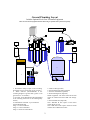
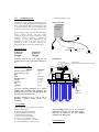
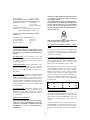
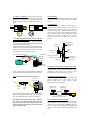
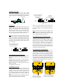
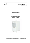
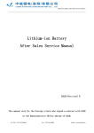
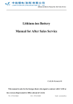
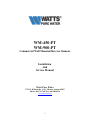
WM-450-PT
WM-900-PT
Commercial Wall Mounted Reverse Osmosis
Installation
And
Service Manual
Watts Pure Water
1725 W. Williams Dr. C-20., Phoenix, Arizona 85027
Phone : 888-774-7405 Fax: 602-588-0356
www.wattspurewater.com
1
General Plumbing Layout
Includes Optional Pre & Post Treatment Equipment
All Pre-& Post treatment equipment shown in this drawing are optional and are purchased separately.
9
9a
4
8
3
7
6
2
22
1
5
1: Pre -Booster Pump (require if the incoming
feed water pressure is less than 35 psi (2.2 bars).
2: Water Softener (Recommended if the
incoming hardness is greater than 7 grains or 120
ppm of CaCo 3 as hardness)
3: Pre -Ultra Violet Disinfection (Recommended
if the incoming feed water is microbiologically
unsafe)
4: WM-900-PT with built –in pre -treatment
(Shown WM-900-PT)
Stage 1: 5-micon sediment
Stage 2: 1-micron sediment
Stage 3: 10-micron carbon block
5: Tank Tee Kit (Optional)
6: Pressurized Storage tank (Optional)
7: Post-UV disinfection (Optional)
8: Final Polishing final (Optional)
Steam Equipment: The final GAC/Calcite filter
would be installed between WM and Storage
tank.
9: Ozone disinfection (Optional)
Note: WM-450 & 900 require a floor drain
within 20 feet of unit.
Note: WM-450 & 900 require electrical outlet
within 8 feet of WM-Control box.
2
1.0
(1) Brass Hex Nipple ¼” FPT
INTRODUCTION:
WM-Control Box
This manual contains important information on the
installation, operation and maintenance of Watts WM Series. Watts WM -PT-Series is designed for use with
a pressurized storage tank. Proper installation and
maintenance will prevent costly equipment downtime.
Watts Water
Systems
Before installing and/or operating Watts WM -Series
Reverse Osmosis System, read this manual
completely. Keep this manual available for future
reference.
Further information is available by
contacting your local Watts Distributor or STS
Department at Watts Pure Water, Inc.-1725 W.
Williams Dr. C-20.- in Phoenix, Arizona-U.S.A.
85027-Phone (888)774-7405, Fax: (602)588-0356.
Power supply
2.0 Specifications:
Motor
Solenoid
WM-450-PT
Production:
WM-900-PT
Production:
450 gpd
900 gpd
TSO switch
WM-Module
Production based on 77o F water temperature and
operating pressure of 150 psi with TDS of 2000 ppm of
Na.
Feed
Back
PressureSolenoi
Pressure
d
Gauge Valve
Gauge
Motor
To Drain
Recovery
Valve
2.1General Guide Lines:
Minimum
Inlet water pressure:35 psi
Water temperature: 36oF
pH:
3
TDS:
Hardness CaCO 3:
Iron Fe:
Chlorine:
Silt:
Turbidity:
Maximum
100 psi
100o F
11
5000 ppm
256 ppm
0.1 ppm
0.1 ppm
0.1
1NTU
Low Pressure
Switch
Low Pressure
Switch is located behind inlet pressure gauge
WM-450-PT
Membrane
TSO
Switch
1/2” or 1”
Inlet port
1/2” Flush
Valve
Permeate
Water Line
The above operating parameters are a general
guideline only. Incoming water chemistry, pretreatment and recovery rate will effect the life and
operation of the RO Membranes.
Warning; Warranty may be void if unit is
improperly operated without proper pretreatment.
Stage 1
Stage 2
Stage 3
3.0 Unpacking:
Check for shipping damage. Report any shipping
damage to freight carrier.
Identify the following components:
(1) WM -Control Box (See drawing)
(1) WM -Module (See drawing)
(15) Feet of 3/8” ID Poly tubing
(15) Feet of ¼” ID Blue Poly tubing
(1) Plastic Connector 3/8”C x ¼” MPT
(1) PVC Bell Reducer ½” FPT x ¼” FPT
Note: Depending on the Pre- & Post treatment
equipment package that was order from Premier.
They may be packed in the same shipping
container as the WM-System.
4.0 Specifications:
3
Warning: The WM-Module must be firmly secured
to a wall that can support the weight of the WMunit during operation.
The mounting bracket of the WM-Module has (3)
slotted keyholes for mounting the WM-Module to
the wall. The head of the screws or bolts should be
of a size that can pass through the larger part of
the slotted keyhole but not the smaller slotted area
that it will slide into.
Inlet connection:
½” FPT or 1” FPT
Water supply line must be at least ½” service.
Incoming water pressure must be greater than 35 psi.
Drain Line connection:
3/8” Tubing or
¼” FTP, ½” FPT
Permeate:
¼” OD Plastic Tubing
M aximum Recovery rate:
1:1
Electrical: 110v/7.2 amps/60Hz (15-amp service)
220v/4.3amps/60Hz (10-amp service)
Electrical supply outlet must be with in 8’ of WMcontrol box.
Mounting weights: of WM -Module with:
10” filter housing
135-lbs. wet
20” filters housing
175-lbs. wet
WM -Control Box:
8-lbs.
WM-Module should be anchored and mounted to a
wall according to local building codes.
5.0 Equipment location:
6.1 Anchoring WM-Module to Block or concrete
walls:
The drawing in the front of the manual is to be
used as a general reference guideline for placement
of any pre & post treatment equipment that you
may have.
Molly bolt or anchoring insert devices should be used
on all brick, concrete block, or concrete walls.
Anchoring devices should be installed according to the
manufacturer instructions.
5.1 WM-Module: To be mounted to a flat wall
surface. WM -Module should be located and mounted
in a location that allows for easy access for future
servicing of pre-filter.
6.2 Anchoring WM-Module to Sheet-rock walls:
The (2) outside mounting Slotted Keyholes on the
WM -Module bracket are on 16” centers to allow
anchoring into wall studs that are on 16” centers.
5.2 WM-Control Box: To be mounted within 5 ft of
WM -Module for the connection of the electrical.
Note: The WM-Control Box should not be located
directly below the WM -Module. See Section 7.0 for
more details.
6.4 If wall studs are not on 16” centers, or the location
of the WM does not allow it be anchored into wall
studs, an additional support brace may be required.
Support brace should be at least 1” thick by 6” wide
and no less than 24 inches in length. Support braces
must be secured into the at least (2) wall studs. The
brace may be glued and additional screws used to
ensure a solid mounting surface for the WM -module
as shown below.
5.3 Pre-Treatment: Depending on the incoming feed
water chemistry, additional pre-treatment may be
needed to address specific water chemistry and to
protect the WM -membranes. Placement of other pretreatment equipment should allow for future access to
the WM -pre-filter. Installation of any additional pretreatment equipment to be done in accordance, with
it’s own manual.
5.4 Post-Treatment: Depending on application, all or
some of post-treatment may be needed and the
location may vary from the general layout. All posttreatment equipment should be installed accordance to
it’s own manual.
7.0 Mounting WM-Control Box:
7.1 The WM -Control box should be located off to the
side or above the WM -Module. Do not install the
WM -Control box below the WM -Module. Water may
spill out of the filter-housing sump during filter
changes.
6.0 Mounting WM-Module:
Locate and mount WM-Module before making any
connection. Premier Manufactured Systems, Inc
assumes no responsibility or liability in mounting
WM-Module to a wall. Use the following as a
guideline only.
7.2 WM -Control box must be mounted within 5 ft. of
the WM -Module, for connection of electrical wires to
the WM -module. The WM -control box come with an
8-ft power cord and require electrical outlet within 8ft.
4
7.3 The WM -Control box has (4) mounting holes.
WM -Control Box weighs only 8 pounds. #12 screws
should hold the WM -Control Box in place. A wall
anchor device should be used to ensure the mounting
screws do not pull out of a wall.
0-100Pressure
Gauge
SS Check
Valve
8.0 Drain line connection:
The drain line should be installed accordance to the
local and state plumbing codes.
8.1 The
3/8” ID
adapted
reducer.
unit may be plumbed to the drain using the
plastic tubing (which is included) or can be
for a hard plumbed using the PVC bell
See drawing below for the correct parts.
Connector Plastic
3/8”C x 1/4” MPT
Drain Control
Needle Valve
1/4” ID Blue
Tubing
Tank Pressure
Switch
TSO
Settings: 40-60 psi
To Pressurized Storage tank
Recycle
Needle Valve
Note: For future servicing of equipment down
stream a ball valves maybe plumbed before and
after pressurized storage tank.
SS Check Valve
To Drain
9.1 Pressurized Storage Tank. For proper operation
of the WM -PT the recommended air pressure setting
in the pressurized storage tank then empty of water is
as follows:
Back Pressure Gauge 0-300 psi
1/4” Brass Hex Nipple
PVC Bell Reducer
1/2” FTP x 1/4” FPT
2 to 10 gallon size tanks:
23 to 46 gallon size tanks:
8.2 Soft plumbed drain line. The WM has been
tested at the factory with soft drain line. You will find
the plastic connector already installed on the outlet
port of the Drain Control Needle Valve. Loosen the
compression nut on the plastic connector and insert the
3/8” OD tubing through the nut and into the connector.
Hands tighten compression nut then tighten with a
wrench. Run 3/8” tubing to a floor drain or sink drain
securing it along the way. Note: Air Gap is required
in the United States for all drain connections.
5 psi
12 psi
USE only pressurized storage tank designed for
RO water.
10.0 Connection of feed water to WM-PT unit.
The water supply feeding into the WM-PT unit
must have a minimum feed water pressure of 35 psi
or 2.4 bars with a flow rate of 2.33 GPM for proper
operation.
10.1 Inlet connection port size.
WM -PT unit inlet port has been reduced to ½” Female
pipe threads at the factory. This bushing may be
removed for plumbing greater than ½” in size. The
maximum inlet port size for the WM -PT unit is 1”
female pipe, threads. Only use Teflon plumbing
tape on all connections into the WM-PT.
8.3 Hard plumbed drain line. Remove the plastic
connector from the outlet port of Drain Control Needle
Valve. Teflon tape the male pipe thread of the ¼”
Brass Hex Nipple and thread into the outlet port of
Drain Control Needle Valve.
Thread PVC Bell Reducer on to the ¼” Brass Hex
Nipple. The Hard drain line maybe run in either ½”
PVC or Copper pipe. Secure drain line according to
local and state plumbing codes.
NOTE: Use back up wrench then tighten all
connections or fittings.
10.2 Pre-Ball Valve.
The WM -unit does not include a ball valve on the
inlet. It is recommend that a ball valve be installed on
the inlet of pre-filters for future servicing.
9.0 Permeate line connecti on: The WM -PT-series
comes with 15 feet of ¼” OD Blue Poly Tubing.
Additional tubing can be added if needed.
11.0 Electrical connection of WM-Module to WMcontrol box.
All electrical connection between module and
control box are color-coded. Do not connect WMcontrol box into power source at this time.
5
11.1 Motor Connection: The electrical connection
between the WM -module and control box for the RO
pump motor is with the self-locking female and male
plugs. Push Male Plug into Female Plug and turn to
lock.
12.0 START UP:
All pre-treatment equipment should have been started
up and be in service before starting up the WM System.
Control
Motor
Female
Male
Box
11.2 Connecting Inlet Solenoid and Low Pressure
Switch (LLP) to control box:
The pink female spade connector RED and BLACK
wires plug into the male terminals of the inlet solenoid
coil as shown in drawing below.
The Blue color female spade connectors WHITE and
GREEN wires plug into the male terminals of the LLP
Switch that are marked COM (common) and N/O
(normally open) as shown in drawing below.
Grey Cable from control box
Black wire
Red wire
Green wire
White
wire
Tee
Brass
1/2” FTP
WM-pre-filter
stage 3
Normally open
1” MPT x 1/2” FPT
terminal
Bushing
Brass Hex
Common
Nipple 1/2”
terminal
If any of the 2 wires to the LPP switch are installed on
the terminal marked N/C the WM -PT will not operate.
11.3 TSO (Tank Pressure switch) connection:
Flush Valve
1/2” FPT Brass
Ball Valve
12.2 Disconnect Permeate Line from Storage Tank
For start up disconnect RO Blue ¼” Poly Tubing from
the storage tank. This way you will be able to see the
production of RO water and be able to adjust
production of the unit and set the recovery rate.
12.3 Drain Control Needle Valve .
Fully open the Drain Control Needle Valve by turning
counter clockwise until it stops. Make sure the
Recycle Needle Valve is fully closed by turning
clockwise. (See Drawing below)
TSO Tank
Pressure Switch
Molex
Female
Plug
Stainless Steel
Braided Flexible
Tubing
Outlet of
Pre-filters
Low Pressure
Safety switch
Solenoid coil 24 volts
12.1 Flush valve
The WM has a built in flush valve after the pretreatment. The flush valve allows to purge both air
and carbon fines out of the pre-filters. A water line
should be attached to the outlet of the flush valve and
run to a drain or into a pail. Open flush valve and turn
on water supply to WM -System. Flush water through
pre-filter for 5 minute or until water run clear of
carbon fines and air. Turn flush valve to the off
position.
Molex
Male
Plug
Drain Control
Needle Valve
turn to open
Male Molex Plug on the TSO (Tank Pressure Switch)
plugs into the Female Molex Plug from the control
box. The Yellow and Brown wire are for the TSO.
Recycle
Needle Valve
turn to close
Back Pressure Gauge 0-300
The TSO is pre-set at the factory with a setting of
40 / 60 psi. The WM will shut down when the
pressure in the pressurized storage tank reaches 60
psi and will start up then the pressure in the tank
drop to 40 psi or below.
12.4 Connecting to electrical supply.
The toggle switch on the WM -control box must be in
the off position. Plug the power cord of the WM control box into electrical outlet. NOTE if wired for
220 volts at connector plug will need to be installed on
the power cord or hard wired into electrical disconnect
box.
6
12.5Inlet pressure gauge.
The Inlet pressure gauge before the Inlet solenoid
valve will be indicating the feed water pressure
reading of the inlet water supply after the built-in prefilter. This pressure reading should be greater than 35
psi.
Inlet pressure
Drain Control Needle Valve
turn to set drain flow
feed pressure into
membrane
gauge
Recycle
Needle Valve
turn to increase recovery
To
Drain
Back Pressure Gauge 0300
Inlet Solenoid
Valve
12.6 Start-up
Turn on WM by putting toggle switch into the “ON”
position. The inlet solenoid will open and the RO
pump will start running. Water will start flowing to
the drain. Allow water to run to the drain for 5
minutes. If there is low water flow to the unit at this
time the unit may osculate off and on at this point in
start-up. Turn off the power and go to section 14.
NOTE: At no time should the Drain Needle Valve
ever be completely closed. RO system must have
some water running to the drain during production of
RO water.
12.9 Shut off the WM by placing the toggle switch
into the off position. Reconnect the permeate ¼” OD
blue tubing to the pressurized storage. Open all valves
down steam of RO on all post treatment.
12.7 After 5 minutes slowly start turning the drain
needle valve clockwise. Watching the feed pressure
gauge on the outlet of the RO pump. Turn the drain
needle valve until the feed pressure gauge reads 150
psi. NOTE the back pressure gauge on the Drain
Assembly will read less than 150 psi. Allow unit to
run for 5 minutes.
12.10 Purging air out of system down stream
At the furthest point down stream of RO unit
including all Post-treatment open a valve or break
open RO water line. Turn on WM by placing toggle
switch into the on position. Allow unit to operate,
until water start to flowing. Close the valve or
reconnect water line. Allow unit to start filling up the
pressurized storage tank. The pressure gauge next to
the TSO will indicate the pressure as it builds up in the
storage tanks. The unit should shut down wants the
pressure in the tank reaches 60-psi.
Drain Control Needle Valve
turn to set drain flow feed
pressure into membrane
To
Drain
13.0 Tank pressure switch adjustment.
The tank pressure switch has been pre-set at the
factory for a 40-60 setting. Due to shipping, the
pressure setting may need to be re-adjusted. Remove
the Grey plastic cover off of the pressure switch.
There will be (2) 3/8 nuts. The center adjustment nut
will increase or decrease the off and on set points
without change the pressure differential between the
two settings. The 3/8-adjustment nut that is offset will
change the pressure differential between OFF and ON
mode of the pressure switch.
Back Pressure Gauge 0-300
12.8 Calculating production of RO water
Using a measuring device that is marked in ounces.
Measure the amount of RO water produced in 15
seconds.
Multiply amount of ounces by 4 = ounces per minute
Multiply ounces per minute by 1440 = ounces per day
Divide ounces per day by 128 = gallons per day.
Repeat same steps for computing concentrate water
flowing to the drain.
Log information into log sheet.
12.8 Setting recovery rate
Very carefully open the 50% recovery needle valve by
turning counter clock-wise and at the same time very
carefully turn the drain needle valve clockwise
keeping the feed pressure into the membrane at 150
psi. See drawing below Do this until the water flow to
the drain and the RO flows are equal in volume and
flow.
Repeat steps 12.8 to make sure the flow rate are
equal for both permeate and concentrate.
7
Turn nut clockwise to
increase both Shut-OFF and
Turn On pressure setting
Turn nut counter clockwise
to lower both shut -off pressure
and turn on pressure settings
14.0 Testing low water pressure safety switch
The low pressure shut down switch has been pre-set at
the factory to shut down the production of the WM
unit if the incoming feed water pressure drops below
18 psi. To provide protection that the RO pump is not
operated in a dry mode.
(h) Any hydrogen peroxide still in storage tank or in
the water lines will be removed by the final
polishing. Or break down to oxygen and water
over 24-hour period.
14.1 To test the LPP the WM must be in operation and
producing RO water. With the unit operating turn off
the incoming feed water supply into the WM. The
WM inlet solenoid valve should close and motor will
shut down and stop producing RO.
At least once a month review operation of unit and
fill in the information required in operational
chart.
MAINTENANCE Schedule
WM-unit pre-filters should be changed once every
3 to 6 months or even sooner depending on
incoming feed water conditions.
14.2 Turn on the incoming feed water supply into the
WM unit and the unit will start up and start producing
RO water automatically.
1.
SPECIAL NOTE: Low water pressure caused by
inadequate water flow from source or by clogged
pre-filter will cause the RO unit to osculate
between off and on. The low-pressure switch
sensing low pressure then the unit is operating
causes the unit to shut down. Then as soon as the
unit shut down the low-pressure switch senses the
correct water pressure and re-starts up. If the unit
is osculating because of this condition, this will
cause major damage to the unit. Turn off unit
immediately. If the condition is cause due to the
lack of water flow increase water line size or add
low water pressure pre-booster pump. Contact
Watts Pure Water STS department.
2.
3.
4.
5.
6.
7.
If osculation is caused by clogged pre-filter, change
pre-filter.
See maintenance schedule filter
changing
8.
9.
Changing Pre-filters
Turn off the unit by placing the toggle switch into
the off position.
Turn off incoming feed water supply to WM unit.
Open flush ball valve to de-pressurize the prefilter housing and drain the water into a pail or
drain.
Remove the filter housing by turning to the left.
Note: A filter-housing wrench may be need.
Drain and remove filter cartridge from housing.
Discard used filter cartridge. DO NOT discard
filter-housing o-ring.
Clean filter housing with warm soapy water.
Rinse with clean water.
Clean and lubricate filter-housing o-ring with KY Jelly or silicone grease. Do not use petroleumbased lubricant.
Inserts filter cartridges into the appropriate filter
housing and reinstall filter housing back into
place turning to the right (hand tight only).
Follow normal start up procedures.
System Disinfecting for consumable water
WM-membrane may need to be replaced once
every 12 to 24 months or sooner depending on the
incoming feed water chemistry and how the unit is
operated:
If System is used to supply RO drinking water for
human consumption disinfection is recommended.
System should be disinfected at least once every 12
months.
(a) Allow system to fill storage tank before
disinfecting post treatment down stream of WM.
(b) Close a ball valve down stream of delivery pump
and open a faucet or line to relief water pressure
from the RO water lines.
(c) Remove all filter cartridges from any post
treatment housing down stream of delivery
pump.
(d) Add 1 teaspoon of hydrogen peroxide to all filter
housings down stream of delivery pump and
reconnect to filter housings without the cartridge.
(e) Add 12 oz. of hydrogen peroxide for every 50
gallons of water in storage tank and wait for 30
minutes.
(f) Open ball valve down stream of delivery pump
and flush 5 to 10 gallons RO water from every
dispensing port.
(g) Replace any post filter cartridge back into their
housings.
Watts Pure Water
Sales and Technical Support Department Toll free
within the United States (1-888-774-7405). Outside
the United States (623 505-1512).
Monday Thurs Friday: 8:00 AM – 5:00 PM
Mountain Standard Time
8