1
INSTALLATION AND
OPERATION MANUAL
LazerData Series 9000E
BARCODE SCANNER/DECODER
PSC Automation, Inc.
675 Basket Road
Webster, New York 14580-9787
(800)-828-6489
(716) 265-1600
(716) 265-6400 (Fax)
INSTALLATION AND OPERATION
MANUAL
LazerData Series 9000E
BARCODE SCANNER/DECODER
Part No. 7902033
Revision E
August 1997
FOREWORD
The purpose of this manual is to provide sufficient information and data
to install, program, operate, and maintain the LazerData Series 9000E
Bar Code Reading System. PSC Automation, Inc. has made every
effort to ensure that the information in this manual is both accurate and
adequate. It is recommended, in the interest of safety and efficiency,
that each section be carefully read before installing or servicing this
system. Special attention should be given to the items outlined in
Section 1, READ THIS FIRST, before proceeding further.
This manual may not be copied or reproduced, in whole or in part,
without the express written consent of PSC Automation, Inc.
Copyright 1997 PSC Automation, Inc.
All Rights Reserved
August 1997
TABLE OF CONTENTS
1 Read This First
Introduction
FCC Class A Statement
NCDRH Compliance Statement
Safety Precautions
Optical Safety
Electrical Safety
1-1
1-1
1-1
1-3
1-3
1-3
2 Introduction
System Description
Technical Specification
Principals of Operation
2-1
2-1
2-3
3 Installation
Introduction
Unpacking and Inspection
Mounting Provision
Power Requirements
Specular Reflection
Mounting Orientation
Raster
3-1
3-1
3-2
3-5
3-5
3-5
3-9
4 Signal Interfaces
Introduction
Local Port
Host Port
I/O Port
Power Connector
Mating Connectors
4-1
4-1
4-2
4-6
4-10
4-11
i
TABLE OF CONTENTS
5 Local Formatting
Introduction
Startup
Terminal Selection
Main Menu
Gate Parameters
Field Definition Summary
Field Definition Detail
Host Port Formatting
Local Port Formatting
Output Pulse Configuration
Save Data/Base Configuration
Diagnostics
Compare String - Summary
Compare String - Detail
5-1
5-2
5-4
5-6
5-7
5-12
5-14
5-19
5-25
5-30
5-34
5-36
5-38
5-40
6 Host Programming
Introduction
Programming
Commands
6-1
6-2
6-3
A ppendix
Glossary of Terms
ii
READ THIS FIRST
INTRODUCTION
This section contains vital information necessary for proper installation,
operation and maintenance of the LazerData Series 9000E
Scanner/Decoder Bar Code Reading System. Each item in this section
should be read completely before proceeding to other sections of this
manual. If any questions arise please contact LazerData Applications
Engineering at 1-800-843-2700 for clarification.
FCC CLASS A STATEMENT
This equipment generates, uses, and can radiate radio frequency energy
and, if not installed and used in accordance with this manual, may cause
interference to radio communications. It has been tested and found to
comply with the limits for a class A computing device pursuant to
Subpart J of Part 15 of the Federal Communication Commission rules,
which are designed to provide reasonable protection against such
interference when operated in a commercial environment. Operation of
this equipment in a residential area is likely to cause interference, in
which case the user, at his own expense, will be required to take
whatever measures may be required to correct the interference.
NCDRH COMPLIANCE STATEMENT
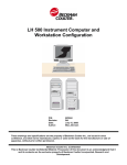
This laser bar code scanning system complies with Standard 21 CFR,
Subchapter J, for Class I and Class II laser products as set forth by the
National Center for Devices and Radiological Health. Any alteration or
adjustment that could result in emission of radiation in excess of the
level established for Class I or Class II laser products is not authorized,
and will void certification of the system as a Class I or Class II laser
product. Figure 1-1 on the following page shows the type and location of
warning labels affixed to the scanner in compliance to the NCDRH
standard. The Caution and Aperture labels do not apply to the Class I
Infrared scanners.
1-1
Series 9000E Scanner/Decoder
NOTE: A ^L (Control L) sent to the Local or Host Port of the Series
9000E Scanner/Decoder will turn the Laser Beam on or off.
Warning Label Placement
Figure 1-1
1-2
READ THIS FIRST
SAFETY PRECAUTIONS
CAUTION
Use of controls, adjustments or performance of
procedures other than those specified herein may
result in exposure to hazardous radiation or
electrical voltages.
The LazerData Series 9000E Bar Code Scanning System incorporates
features that provide for maximum safety. However, it must be
recognized that any equipment employing electrical voltage and emitting
direct or scattered radiation may cause serious damage and/or personal
injury if improperly handled.
The following are recommended
safeguards that should be observed at all times.
OPTICAL SAFETY
Never stare directly into the laser beam.
CAUTION:
Use of optical instruments with this product will
increase eye hazard.
ELECTRICAL SAFETY
Disconnect the main power line before working on any electrical
equipment.
Always use insulated tools.
1-3
Series 9000E Scanner/Decoder
1-4
INTRODUCTION
SYSTEM DESCRIPTION
The LazerData Series 9000E Scanner/Decoder offers scanning and
decoding functions in a single package measuring only 2.5" wide X 2.5"
high X 3.85" long. The durable extruded aluminum housing affords
maximum protection for the scanning optics and decoding circuitry.
Scanning at speeds from 100 to 1500 scans per second, it is ideal for
applications such as high speed packaging machines. The laser diode
light source offers the long operating life associated with solid state
devices. Systems configuration is accomplished through the use of an
ordinary computer terminal and a Series of menu screens assuring that
no special programming skills are necessary to setup the unit. The
scanner can communicate with peripheral devices using either RS-232,
RS-422 or RS-485 protocols. Using an external power supply keeps the
scanner size to a minimum and reduces the internal operating
temperature.
TECHNICAL SPECIFICATIONS
Light Source
Type:
Output Wavelength:
Safety Class:
Operating Life:
Scanning Parameters
Type:
Rate:
Laser Diode
670-680 nm--visible red,
840 nm--infrared or
1330 nm--infrared,
depending on model.
Class II
Greater than 50,000 hours
Rotating polygon, unidirectional scan
500 to 1000 sweeps per second,
depending on model. 1500 scan rate
available for special applications.
2-1
Series 9000E Scanner/Decoder
Decoding Capability
C11, C39, C93, C128, C49 (2 row
numeric only), Codabar, UPCE*,
UPCA*, EAN8*, EAN13*, I2/5, Binary,
AS10, Pharmacode, ISTR. (* with or
without supplemental.)
Host Port
Hardware Protocols:
Software Protocols:
Wiring:
Baud Rate:
Local Port
Hardware Protocol:
Software Protocol:
Wiring:
Baud Rate:
I/O Port
Inputs:
Outputs:
Wiring:
LED Indicators
BI-color LED:
Amber LED:
Power Requirements
Input Voltages:
Wiring:
RS-232C, RS-422 or RS-485
ACK/NAK, XON/XOFF, LazerData
Intermec Mult-idrop, or None.
DE9S Connector
User Programmable, 300 to 38,400
RS-232C
XON/XOFF, None
DE9P Connector
User Programmable, 300 to 38,400. Set
to 9600 at manufacture.
Gate, Push Button Compare
Good Read, No Read, Good Compare,
No Compare, Digitized Output.
DE15S Connector
Good Read-Blinks Green
No Read-Blinks Red
Not Functional on Infrared Scanners
Indicates Laser Emission
Not Functional on Infrared Scanners
+5 VDC +5%, 860 mA.
+12 VDC +5%, 300 mA.
5-pin keyed connector
2-2
INTRODUCTION
PRINCIPLES OF OPERATION
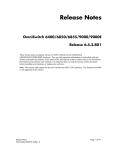
The LazerData Series 9000E bar code scanner/decoder uses a light
beam generated by a laser diode light source to illuminate bar code
labels. The laser beam is deflected in a fan shaped pattern across the
label. The reflected light of the laser beam, representing the light and
dark bars of the coded label, is then collected and focused by a lens
onto a photodiode, processed, then converted to a digital signal. The
signal is a close approximation of the bar code pattern as shown in
Figure 2-1.
This signal is then analyzed by a high speed
microprocessor. The bars and spaces in the code are converted to the
numeric or alphabetic characters represented by the bar code symbol.
After the label is decoded, the characters are transmitted via the Host
and Local Port to an external device or host computer.
Bar Code and Digital Signal
Figure 2-1
In addition to reading the code, the scanner can compare the code that
has been read to codes programmed into it's memory and output signals
indicating that a comparison has or has not occurred. The scanner can
also accept a gate input signal indicating that a code is in position to be
read. When the gating input is used, only one data transmission is made
for each bar code presented to the scanner. The scanner also outputs
separate logic level pulses when Good Read, No Read, Good Compare
and No Compare conditions occur.
2-3
Series 9000E Scanner/Decoder
2-4
INSTALLATION
INTRODUCTION
The LazerData Series 9000E Scanner/Decoder is designed for easy
installation in many diverse applications and, because of its small size
and light weight, can be mounted with common hardware. The user
may fabricate a custom mounting bracket or use the mounting holes
provided. The scanner can be mounted in any orientation, but label
position, and motion relative to the scanner dictate optimum position and
distance, as discussed in this section.
UNPACKING AND INSPECTION
Upon receipt of the Series 9000E Scanner/Decoder unit, it should be
carefully unpacked and inspected.
Remove all documentation (packing lists, manuals, etc.) from
shipping container.
Carefully remove the packing material from around the scanner,
and lift the unit from the shipping container.
Do not discard packing material. If your scanner ever needs repair,
you are requested to return the unit in its original container.
Check to ensure all items have been received. Standard package
content includes:
Series 9000E Scanner/Decoder
Local Port Cable (part # 1702076)
Host Port Mating Connector (part # Y260020)
I/O Port Mating Connector (part # Y259930)
Back shells (part # 7651021)
Power Connector (Some Models)
Power Supply (part # 1902032)
Manual (part # 7902033)
3-1
Series 9000E Scanner/Decoder
Inspect all items received for any visible damage that may have been
incurred during shipping. Of particular interest is the glass window at the
front of the scanner unit.
If any items are missing or damaged, immediately notify the carrier and
Customer Administration at PSC Automation, Inc. Call 1-800-843-2700.
Maintain all shipping documentation, containers, and packing materials
until discrepancies are cleared.
MOUNTING PROVISION
The fundamental mounting of the scanner is provided for by eight
through holes in the housing designed to accommodate #6 mounting
hardware. Mounting brackets may be fabricated by user if deemed
necessary. Figure 3-1 illustrates the overall dimensions of the scanning
unit as well as the position of the mounting holes relative to the scanning
beam location. The installation of the Series 9000E Scanner/Decoder is
straight forward and will be successful if some simple guidelines are
followed.
Install scanner unit in locations that are:
Protected from collisions with packages that may be passing close
to the scanner.
A reasonable operating environment with a temperature between 0
and 50 degrees centigrade (32 and 122 degrees Fahrenheit) and
away from extreme heat sources.
Not in a high electrical noise area; for example, near large AC
motors or solenoids.
Away from high vibration areas.
Easily accessible for service and adjustment.
3-2
INSTALLATION
Dimensions
Figure 3-1
3-3
Series 9000E Scanner/Decoder
POWER REQUIREMENTS
The Series 9000E Scanner/Decoder is powered from a multiple-voltage
DC power source. Voltages required are +5 VDC @860 mA. and +12
VDC @ 300 mA. These voltages are supplied to the unit through a
keyed 5-pin power connector. The I/O Port is an alternate connection
for input power. For connector wiring consult Section 4, Signal
Interfaces.
SPECULAR REFLECTION
Bar code reading scanners can be blinded by specular reflections from
mirror-like surfaces on the bar code label and make it difficult or
impossible to obtain an accurate reading. This occurs when code
symbols are printed on glossy material or a plastic coating is applied
over the code symbol for protection. In general, if the bar code looks
shiny to the eye, it should be treated as a specular code. Specular
reflection can be eliminated by mounting the scanner at an angle
relative to the code. Angles of 10 to 15 degrees are normally used. Do
not tilt the scanner in the direction of the sweep, but perpendicular to
that direction. Figure 3-2 illustrates proper scanner mounting for bar
codes with mirror-like surfaces.
Scanner Mounting for Bar Codes with Mirror-Like Surfaces
Figure 3-2
3-4
INSTALLATION
MOUNTING ORIENTATION
Optimum operation of the bar code scanner demands proper orientation
of the scanner relative to the bar code label it is to read. It is not
possible to cover all situations so general rules are provided here. The
Applications Engineering Group at PSC Automation, Inc. is available to
assist in establishing mounting parameters in unusual situations. Call
(800) 843-2700 for assistance.
The optimum distance from the scanner to the bar code label varies with
the printing density of the barcode. Printing density refers to the width of
the smallest bar or space in the code symbol. Higher density labels
(narrower bars and spaces) must be closer to the scanner to be read,
while lower density labels (wider bars and spaces) can be read further
away. Figure 3-3 illustrates typical reading distances for several widths
of bars and spaces. The closest distance from scanner to code is
usually, but not limited to, 2.0 inches. The distances shown are typical
and meant to illustrate the performance capabilities of the scanner.
If density or bar width information about the code symbol is not known,
the optimum operating distance can be determined experimentally.
Connect a terminal to the Local Port as outlined in Section 5, Local
Programming. Enter the Configuration Menu. Select Page 2, Field
Parameters. Select the correct algorithm for the barcode to be used.
Return to the Main Menu and select Page 7, Diagnostics. Select Read
Percentage Test. Adjust the distance from the scanner to the barcode
label while viewing the diagnostics display. Find the distance where the
values displayed for #Decodes is the largest. This is the optimum
distance for that particular label. For most applications the label will be
read reliably at a value of 95 or more decodes. This operating distance
will be the center of the operating range for the label. Type CFG
<enter> to return to the main menu and turn off diagnostics mode.
3-5
Series 9000E Scanner/Decoder
Operating Distance and Beam Sweep Width of Various Bar Sizes
Figure 3-3
3-6
INSTALLATION
In addition to being the correct distance from the scanner, the scan line
must pass through the entire code symbol including the quiet zone at the
beginning and end of the code. The quiet zone is a white area at least
ten times the width of a narrow bar in the code. This is illustrated in
Figure 3-4 below.
Scanning Beam Position
Figure 3-4
The more times the scanning beam passes through the entire code
symbol, the greater is the probability of successfully reading the code.
Figure 3-5 shows a method of calculating the number of passes the
scanning beam will make over the code symbol for two orientations. In
order to perform this calculation the user must know the speed,
orientation of the code symbol ("Ladder" or "Picket Fence"), the distance
from the scanner to the code and the dimensions of the bar code. In
addition, the sweep speed of the scanner and the scanning beam width
must be known. The scan speed was specified when the scanner was
ordered. The beam width can be determined using Figure 3-3. If the
user has a choice of mounting orientation, data for both orientations
should be calculated. The orientation yielding the most sweeps over the
code should be used.
3-7
Series 9000E Scanner/Decoder
Beam Sweeps Over Code
Figure 3-5
3-8
INSTALLATION
RASTER
Some models of the Series 9000E Scanner/Decoder are supplied with a
raster scan option. Not only does the beam scan horizontally but it is
also incremented vertically so as to sweep an area. The area covered
depends on the raster deflection and the distance from the scanner. The
unit is available with 5o, 10o, 20o, and 30o deflection. Figure 3-6 below
shows the area covered for various deflections and distances from the
scanner. For 500-scan/sec. models, six sweeps of the beam are equally
spaced over the raster height. For 1000-scan/sec. models, twelve
sweeps are equally spaced over the raster height.
Raster Width for Various Operating Distances
Figure 3-6
3-9
Series 9000E Scanner/Decoder
3-10
SIGNAL INTERFACES
INTRODUCTION
All interface signals are contained on three D-type subminiature
connectors at the rear of the scanner housing. Connectors are labeled
LOCAL, HOST, and USER I/O. The LOCAL Connector contains the RS232C signals for a serial terminal that can be used to program the
system parameters and monitor activity. The HOST Connector contains
the RS-232C, RS-422, or optional RS-485 signals that will be sent to the
host computer or other control device. The USER I/O Connector
provides logic level status pulse outputs, gating and push-button
compare inputs. A 5-pin circular connector supplies power to the
scanner. +5 VDC, and +12 VDC are required.
LOCAL PORT
This port is designed to accept a serial RS-232 terminal to configure the
system operating parameters and monitor scanner operation if desired.
It is set to 9600 baud, 1 start bit, 8 data bits, no parity bit, 1 stop bit
(9600 N81) at manufacture. A 50-foot maximum cable length is
suggested. Interface is through a DE9P connector as shown below.
DE9P Connector
PIN
NAME
DESCRIPTION
4-1
DIRECTION
Series 9000E Scanner/Decoder
1
N/C
No Connection
2
TXD
Transmit Data
Out
3
RXD
Receive Data
In
4
N/C
No Connection
5
GND
Common Ground
6
N/C
No Connection
7
N/C
No Connection
8
N/C
No Connection
9
N/C
No Connection
Pin 2
TRANSMIT DATA - Data Transmitted from the SERIES 9000E
SCANNER/DECODER to the local programming terminal.
Transmission format is serial ASCII, 1 Start Bit, 8 Data Bits, No
Parity Bit, 1 Stop Bit. Baud rate is set at 9600.
Pin 3
RECEIVE DATA - Data transmitted from the local programming
terminal to the Series 9000E Scanner/Decoder. Transmission
format is serial ASCII, as above.
Pin 5
COMMON GROUND - Ground terminal common to both
Transmit and Receive Data Lines.
HOST PORT
The Host Port is designed to provide RS-232, RS-422, or optional RS485 communications to a host computer or other intelligent peripheral
device. The type of communications used is user-programmable and is
selected on Page 3 of the Programming Menus. When selecting RS232
4-2
SIGNAL INTERFACES
communications, a 50-ft. maximum cable length is suggested. With
RS-422 or RS-485 communications, cable lengths up to 500 feet can be
used. Interface is made via a DE9S connector as shown below. Pin
assignments vary depending on the hardware protocol selected.
Connections for the various protocols are shown in the following tables.
DE9S Connector
RS-232 Connections
PIN
NAME
DESCRIPTION
DIRECTION
1
N/C
No Connection
2
TXD
Transmit Data
Out
3
RXD
Receive Data
In
4
DSR
Data Set Ready
In
5
GND
Common Ground
6
DTR
Data Terminal Ready
Out
7
CTS
Clear to Send
In
8
RTS
Request to Send
Out
9
N/C
No Connection
Pin 2
TRANSMIT DATA - Data transmitted from the Series 9000E
Scanner/Decoder to the host computer. Transmission is serial
ASCII. Format is user programmable.
Pin 3
RECEIVE DATA - Data transmitted from the Host Computer to
the Series 9000E Scanner/Decoder. Transmission is serial
ASCII. Format is user programmable.
Pin 4
DATA SET READY - A signal sent from the Host Computer to
the Series 9000E Scanner/Decoder to indicate that it is on-line.
4-3
Series 9000E Scanner/Decoder
Pin 5
lines.
COMMON GROUND - Ground terminal common to all signal
Pin 6
DATA TERMINAL READY - A signal sent from the Series 9000E
Scanner/Decoder to the Host Computer to indicate that it is online.
Pin 7
CLEAR TO SEND - A signal sent from the Host Computer to the
Series 9000E Scanner/Decoder as an acknowledgment to the
Request to Send signal, and giving permission to send data.
Configuration is user programmable.
Pin 8
REQUEST TO SEND - A signal sent from the Series 9000E
Scanner/Decoder to the Host Computer indicating that it has
data to send. Configuration is user programmable.
RS-422 Connections
Pin 1
PIN
NAME
DESCRIPTION
DIRECTION
1
RXD-
Receive Data -
In
2
TXD+
Transmit Data +
Out
3
N/C
No Connection
4
N/C
No Connection
5
GND
Common Ground
6
N/C
No Connection
7
N/C
No Connection
8
TXD-
Transmit Data -
Out
9
RXD+
Receive Data +
In
RECEIVE DATA (-) - Negative connection for data transmitted
from the Host Computer to the Series 9000E Scanner/Decoder.
4-4
SIGNAL INTERFACES
Pin 2
TRANSMIT DATA (+) - Positive connection for data transmitted
from the Series 9000E Scanner/Decoder to the Host Computer.
Transmission is serial ASCII. Format is user-programmable.
Pin 5
COMMON GROUND - Ground connection common to all
signals.
Pin 8
TRANSMIT DATA (-) - Negative connection for data transmitted
from the SERIES 9000E Scanner/Decoder to the Host
Computer.
Pin 9
RECEIVE DATA (+) - Positive connection for data transmitted
from the Host Computer to the Series 9000E Scanner/Decoder.
Transmission is serial ASCII. Format is user-programmable.
RS-485 Connections
PIN
NAME
DESCRIPTION
DIRECTION
1
RS-485 (-)
Data -
Bi-directional
2
N/C
No Connection
3
N/C
No Connection
4
N/C
No Connection
5
GND
Common Ground
6
N/C
No Connection
7
N/C
No Connection
8
N/C
No Connection-
9
RS-485 (+)
Data +
Bi-directional
Pin 1
RS-485 (-) - Signal for three wire Party Line configuration.
Pin 5
Common Ground - Ground common to all signals.
Pin 9
RS-485 (+) - Signal for three wire Party Line configuration.
4-5
Series 9000E Scanner/Decoder
I/O PORT
This port is designed to provide status output pulses and accept input
signals for gating and push button compare. Output pulses are provided
for Good Read, No Read, Good Compare, and No Compare Conditions.
Pins 1, 6 and 15 can be used as an alternate method of supplying
scanner power. If the scanner is powered using the power connector,
these pins may be used as a voltage source to power external hardware
such as a gate sensor. Connections are made through a DE-15S
connector as shown below.
DE-15S Connector
4-6
SIGNAL INTERFACES
PIN
NAME
DESCRIPTION
DIRECTION
1
-12VDC
-12VDC Power
Input/Output
2
GND
Common Ground
3
GC
Good Compare
Output
4
NC
No Compare
Output
5
Reserved*
6
+12VDC
+12VDC Power
Input/Output
7
GND
Common Ground
8
GND
Common Ground
9
GR
Good Read
Output
10
NR
No Read
Output
11
GND
Common Ground
12
O/D
Digital Output
Output
13
Gate
Gate Input
Input
14
PBC
Push Button Compare
Input
15
+5VDC
+5VDC Power
Input/Output
*NOTE: DO NOT MAKE ANY CONNECTION TO THIS PIN.
Pin 1
-12 VDC INPUT/OUTPUT - Alternate input power connection to
the Series 9000E Scanner/Decoder. -12 VDC + 5% @ 300 mA.
required. -12 VDC available at this pin when power connector is
used.
Pin 2
COMMON GROUND - Ground connection common to all
signals.
Pin 3
GOOD COMPARE - User programmable TTL level output pulse
from Series 9000E Scanner/Decoder on each code read that
compares with a compare buffer entry (open collector on some
models).
4-7
Series 9000E Scanner/Decoder
Pin 4
NO COMPARE - User-programmable TTL level output pulse for
each code read that does not compare with a compare buffer
entry (open collector on some models).
Pin 5
DO NOT MAKE
RESERVED.
Pin 6
+12 VDC INPUT/OUTPUT - Alternate input power connection to
the Series 9000E Scanner/Decoder. +12 VDC + 5% @ 300 mA.
required. +12 VDC available at this pin when power connector
is used.
ANY
CONNECTION
TO
THIS
PIN.
Pin 7,8 COMMON GROUND - Ground connection common to all
signals.
Pin 9
GOOD READ - User-programmable TTL level output pulse for
each code read by the Series 9000E Scanner/Decoder. (Open
collector on some models).
Pin 10 NO READ - User-programmable TTL level output pulse for each
code not successfully decoded. (Open collector on some
models).
Pin 11 COMMON GROUND - Ground connection common to all
signals.
Pin 12 DIGITAL OUTPUT - TTL level output. Bar = 1 Space = 0.
Refer to Section 2, Figure 2-1.
Pin 13 GATE INPUT - Input signal to the Series 9000E
Scanner/Decoder indicating that a code is present. Can be
supplied by a switch, a photoelectric sensor, or an input voltage.
The input voltage at this terminal is 30 VDC maximum.
Connecting this terminal to ground or applying a voltage less
than 0.8 V gates the scanner. See Figure 4-1.
Pin 14 PUSH BUTTON COMPARE - Shorting between this terminal
and ground will enter the next code read into the compare
buffer. Scanner will automatically be set to compare mode
when push button is used.
4-8
SIGNAL INTERFACES
Pin 15 5 VDC input/output - Alternate input power connection to Series
9000E Scanner/Decoder. 5 VDC+5% @ 860 mA required. 5
VDC available at this pin when power connector is used.
Note:
Open collector outputs are capable of switching up to 24 VDC at
currents of up to 100 mA.
Typical Gate Connection
Figure 4-1
4-9
Series 9000E Scanner/Decoder
POWER CONNECTOR
The Power Connector is used to supply input power to Series 9000E
Scanner/Decoder. Terminal locations are shown below. The I/O Port
can be used as an alternative method of supplying power. The table
below lists the voltages required and the minimum required current for
each voltage.
PIN
CONNECTION
1
Ground
2
+12 VDC, 300 mA. minimum
3
Ground
4
-12 VDC, 300 mA. minimum
5
+5 VDC, 860 mA. minimum
4-10
SIGNAL INTERFACES
MATING CONNECTORS
Mating connectors are available from LazerData for all connectors used
on the Series 9000E Scanner/Decoder. They can be ordered by the part
numbers listed below.
Call Customer Administration at (800) 843-2700.
MATES TO
PART No.
DESCRIPTION
LOCAL PORT
Y259600
7651021
Connector
Back for above
HOST PORT
Y260020
7651021
Connector
Back for above
I/O PORT
Y259930
7651021
Connector
Back for above
POWER
5601006
Connector
4-11
Series 9000E Scanner/Decoder
4-12
LOCAL FORMATTING
INTRODUCTION
The LazerData Series 9000E Bar Code Scanner/Decoder is capable of
being configured with a computer terminal or a computer programmed to
emulate a terminal. When power is first applied to the system, a Startup
screen appears on the terminal. Type CFG and press the ENTER key
on the terminal keyboard to display the Scanner Configuration Screen.
A terminal emulation must be chosen before displaying the Main Menu
Screen. The Main Menu screen provides access to eight unique screens.
These eight screens allow the user to configure the Series 9000E
Scanner/Decoder to meet the unique requirements of the application.
5-1
Series 9000E Scanner/Decoder
Downloading ...............................
Host Port RS232 9600 NONE EIGHT ONE
Local Port RS232 9600 NONE EIGHT ONE
LD9000E
AB-123
AB-123
AB-123
AB-123
AB-123
AB-123
AB-123
AB-123
STARTUP/SHOW BAR CODES
Purpose of Screen:
Indicates that power is on and the system is ready to read bar codes.
Displays enabled bar codes currently being scanned.
Field Descriptions:
When power is applied to the Series 9000E Bar Code Scanner/Decoder
a startup screen will appear on the terminal. The startup screen will
indicate that the scanner is downloading it’s program from memory and
is loading the database most recently saved. Once this is completed the
Host and Local Port comm-unication parameters will be displayed. The
scanner will then display LD9000E on the terminal screen.
Once loading is complete, the Series 9000E Bar Code Scanner/Decoder
will begin transmitting decoded bar codes to the terminal screen. If
5-2
LOCAL FORMATTING
there is no bar code label in front of the scanner, or the gate is not
enabled the terminal will remain blank.
Operator Actions:
1.
To display bar code values on the local terminal, put a bar code
label in front of the Series 9000E Bar Code Scanner/Decoder. If
the bar code type has been enabled it will be displayed when
decoded.
2.
To access the Setup Screen type CFG and press ENTER.
Note:
To return to the Display Bar code screen from the Main Menu
select the X = EXIT TO READ MODE option.
5-3
Series 9000E Scanner/Decoder
LazerData LD9000E SCANNER CONFIGURATION SYSTEM
LAZERDATA MODEL: LD9000E Revision 1.60 May 18, 1995
Please select one of the following terminal
types by entering the number indicated:
1 = DEC VT100, ANSI, LCDOS
2 = TELEVIDEO 912, 920
3 = WYSE 30
4 = LazerData SSDL
Enter 1-4 or <CR>: 1
TERMINAL SELECTION
Purpose of Screen:
Indicates the start of the Configuration Mode.
Displays the current scanner software version identification.
Allows user to select the type of terminal that will be used for
programming.
Field Descriptions:
The menu presents four choices of terminals. Select the choice that
represents the terminal being used. If a terminal emulation program is
being used, the program can be set to emulate any of the typical types
listed. All terminal types have screen formatting capabilities, so the
displays will look like those presented here.
Operator Actions:
5-4
LOCAL FORMATTING
Select the appropriate terminal type by typing in the corresponding
number. Press ENTER to confirm selection and move to the MAIN
MENU. Terminal #1 is the default option. If choosing this terminal, just
press ENTER to move to the MAIN MENU.
5-5
Series 9000E Scanner/Decoder
MAIN MENU
1 = GATE PARAMETERS
2 = FIELD DEFINITIONS
3 = HOST PORT PARAMETERS
4 = LOCAL PORT PARAMETERS
5 = INPUT/OUTPUT PULSE PARAMETERS
6 = SAVE/DEFAULT CONFIGURATION
7 = READ RATE DIAGNOSTICS
8 = COMPARE STRINGS
x = EXIT TO READ MODE
Enter selection: 1
MAIN MENU
Purpose of Screen:
This screen allows you to access eight setup and configuration screens.
Field Descriptions:
Menu items 1 through 8 provide access to detailed menus for setting the
configuration parameters to the specific requirement of your system. If
the system is being configured for the first time, the menus can be
accessed in order. If changes are desired under a particular menu, that
menu can be accessed directly.
The X = EXIT TO READ MODE selection returns you to a blank screen
to display the bar code currently being read.
Operator Action:
5-6
LOCAL FORMATTING
Type the number of the selection you wish to make. The screen for the
selection you make will be displayed.
GATE CONFIGURATION
LASER MODE OF OPERATION:
Continuous
LASER BEAM TRACKING:
NO
TRANSMIT AFTER:
GATE CLOSES
HOST START SCAN CHARACTER:
<SI>
HOST STOP SCAN CHARACTER:
<ETX>
ACK/NAK TIMEOUT VALUE:
0 msec
(0 - 9999 msec for host port only)
DATA CHANGE TIMEOUT VALUE:
0 msec
(0 - 30000 msec)
GATE INPUT DEBOUNCE TIME:
1 msec
(1 - 999 msec for the host port only)
GATE TIMEOUT VALUE:
0 msec
(0 - 30000 msec)
COMPARE MODE:
NO
(See Main Menu Option 8 for Setup)
MASTER/SLAVE MODE:
NO
(Send Gate Open/Close message to the multiplexor)
KEYS: SPACE=TOGGLE+ BKSPACE=TOGGLE- <CTRL-U>=LAST SCREEN
PAGE 1 - GATE PARAMETERS
Purpose of Screen:
This screen allows the user to set the mode of operation. The user may
select the method of signaling the Series 9000E Bar Code
Scanner/Decoder to read a bar code and assure that only a single
transmission is made for each bar code read.
The user can also control when that transmission is made, and program
the laser beam to follow the gate mode and turn on only when a bar
code is present.
Field Descriptions:
5-7
Series 9000E Scanner/Decoder
LASER MODE OF OPERATION
Choices are:
CONTINUOUS - The 9000E Scanner/Decoder reads, decodes
and transmits continuously. Data for every read is transmitted.
No gating is performed.
DATA CHANGE MODE BUFFERED - Once a bar code is read
and the data transmitted the 9000E Scanner/Decoder will not
recognize that bar code again until a different bar code has been
decoded.
HARDWARE GATE MODE - Using an external device (as
outlined on Page 4-8) the scanner is gated to read when a bar
code is present. Only a single data transmission is made for
each gate signal.
SOFTWARE GATE MODE - The Host computer may be
programmed to gate the 9000E Scanner/Decoder via an ASCII
start and stop signal.
HIGH SPEED MODE - Same as hardware gate mode but only
outputs are triggered. The label is not transmitted.
DATA CHANGE MODE WITH TIMEOUT - Allows the user to
specify a TIMEOUT value before 9000E Scanner/Decoder will
read the next bar code.
LASER BEAM TRACKING - Selecting NO will leave the laser beam on
at all times. Selecting YES will turn the laser beam on when a gate
signal is received and turn the beam off when the gate is closed. This
will insure that the beam is on only when necessary.
TRANSMIT AFTER - The two choices available are CLOSE and READ.
Selecting READ will cause the 9000E Scanner/Decoder to transmit the
bar code data immediately after a successful read. Selecting CLOSE
will cause the data transmission to be delayed until the close of the gate
signal.
HOST START SCAN CHARACTER - The host computer may be used
to gate the 9000E Scanner/Decoder . The start of each gate must be
5-8
LOCAL FORMATTING
specified as a character or string of characters. Any two character string
can be specified but normally ASCII control characters are used.
The default character string, SI (Shift In) has been programmed. It may
be changed by the user if desired. When these characters are used they
must be bracketed by < >.
HOST STOP SCAN CHARACTER - The host computer character to end
the gate period can also be specified as a character or string of
characters. The default string, <ETX> has been programmed. It may
be changed to any two character ASCII string if desired.
ACK/NAK TIMEOUT VALUE - If ACK/NAK software protocol is selected,
each time a label is read it is sent to the Host for confirmation. If the
host answers ACK (CTRL-F), the scanner can then immediately read the
next label. If the host answers NAK (CTRL-U) or gives no response in
the allotted time then the scanner will resend the label. The scanner will
resend the label to the host up to 5 times.
DATA CHANGE TIMEOUT VALUE - The data change mode can be
modified to recognize the same code again after a set period of time. In
Data Change timeout, once the label leaves the field, a timer is started.
If at the end of the set time the same bar code is presented to the
scanner again, it will be considered a new code. Values specified can
range from 0 to 30000 msec.
GATE INPUT DEBOUNCE TIME - If a switch or relay contact is used for
a gate signal, a debounce time may be necessary. Times will have to
be determined experimentally. Once a gate signal is detected, it must
be present for the set time before it is considered valid. Debounce time
may be specified from 1 to 999 msec.
GATE TIMEOUT VALUE - The Gate Timeout Value is used to simulate
a close gate signal. When the time set has expired the gate will close
and either transmit the bar code data or a No Read. The timer will
ignore all activity on the Gate line until it has timed out. When a new
open gate signal happens the timer starts counting down again.
COMPARE MODE - Activates the Compare String mode. (See Page 8 Compare Strings) for information on compare string options.
5-9
Series 9000E Scanner/Decoder
MASTER/SLAVE MODE - This option will send a multiplexor open
message, scanner label data and then a multiplexor close message.
The open message consists of STX SI CAN CR. The close message
consists of STX SO CAN CR.
Operator Action:
1.
When the cursor is positioned on the LASER MODE OF
OPERATION line, press SPACE to display the desired setting.
Press ENTER to select the choice and move the cursor to the next
line.
2.
Position the cursor on the LASER BEAM TRACKING line. Press
SPACE to change the settings from YES to NO. When the desired
setting is displayed press ENTER to enter the choice and move the
cursor to the next line.
3.
With the cursor positioned on the TRANSMIT AFTER line press
SPACE to change the settings from GATE CLOSES to READ and
back. When the desired setting is displayed, press ENTER to enter
the choice and move the cursor to the next line.
4.
Position the cursor at the end of the HOST START SCAN
CHARACTER line. To accept the currently selected character
string press ENTER. To change the character press BACK SPACE
to delete the present string and enter the new character string.
Press ENTER to proceed to the next line.
Position the cursor at the end of the HOST STOP SCAN
CHARACTER line. To accept the currently selected character
string press ENTER. To change the character press BACK SPACE
to delete the current string and enter the new character string.
Press ENTER to proceed to the next line.
5.
6.
With the cursor on the ACK/NAK TIMEOUT VALUE line enter the
desired value in milliseconds. This value can be between 0 and
9999 milliseconds. Press ENTER to enter the value and move to
the next line.
7.
With the cursor on the GATE CONTROL DEBOUNCE VALUE line,
enter the desired value in milliseconds.
5-10
LOCAL FORMATTING
8.
With the cursor on the GATE TIMEOUT VALUE line, enter the
desired value in milliseconds.
9.
With the cursor on the COMPARE MODE line use the SPACE BAR
to toggle between the choices; YES and NO. Press ENTER to
select.
10. With the cursor on the MASTER/SLAVE MODE line use the
SPACE BAR to toggle between the choices; YES and NO. Press
ENTER to select.
5-11
Series 9000E Scanner/Decoder
FIELD DEFINITION SUMMARY SCREEN
NO. CODE TYPES
01 C_39
LENGTHS
0
SELECT ACTION:
KEYS: SPACE=TOGGLE+ BKSPACE=TOGGLE- <CTRL-U>=LAST SCREEN
PAGE 2 - FIELD DEFINITION SUMMARY
Purpose of Screen:
Displays a summary of how each previously entered field is defined.
Also lets the user edit, delete or insert fields.
Field Descriptions:
A total of up to six fields can be listed. Each listing is a summary of how
a field is defined. Existing fields can be edited or deleted. New Fields
can be inserted.
Note:
Think of a field as an encapsulated object that grabs things. the
entries made in the Definition for Field Number screen (Page 2,
level 2) are simply a set of filters the field uses to filter out the
things it does not want to grab. Each field allows up to 10 code
5-12
LOCAL FORMATTING
type/length combinations (i.e., ten types of code each with their
own number of characters). More than one field turned on
means that the user is looking for more than one label on a
package.
Operator Actions:
Choose EDIT, DELETE, or INSERT by typing in E, D, or I at the
SELECT ACTION prompt.
If DELETE is chosen, the ENTER FIELD NUMBER TO DELETE: prompt
will appear. Enter the Field number 1 through 6. The entire Field will be
deleted from the display.
If a Field is to be edited or inserted, enter the number of the Field at the
prompt, and the next screen will be displayed.
DEFINITION FOR FIELD NO: 01
CODE TYPE
C-39
OFF
OFF
OFF
OFF
OFF
OFF
OFF
OFF
OFF
MIT S/S
XMIT CHK DGT
NO
NO
NO
NO
NO
NO
NO
NO
NO
NO
NO
NO
NO
NO
NO
NO
NO
NO
NO
NO
LENGTH
0
0
0
0
0
0
0
0
0
0
HOST GOOD READ XMIT FORMAT:
LOCAL GOOD READ XMIT FORMAT:
HOST NO READ XMIT FORMAT:
LOCAL NO READ XMIT FORMAT:
HOST READ CONFLICT XMIT FORMAT:
LOCAL READ CONFLICT XMIT FORMAT:
LABEL MASK:
READ CNTS
1
1
1
1
1
1
1
1
1
1
%D%
%D%
NR
NR
%D%
%D%
NO
KEYS: SPACE=TOGGLE+ BKSPACE=TOGGLE- <CTRL-U>=LAST SCREEN
5-13
Series 9000E Scanner/Decoder
PAGE 2 - LEVEL 2 FIELD DEFINITION
Purpose of Screen:
Allows the user to edit existing entries and insert new entries as well as
specify data that will be transmitted along with the bar code data.
Field Descriptions:
CODE TYPE - Any data previously entered will be displayed. If none, all
the entries in this column will read OFF.
XMIT S/S - (Transmit Start/Stop). This controls transmission of Start
and Stop characters with the bar code data. Not all bar codes have
start/stop characters. Not all start/stop characters are transmittable.
Length (number of characters) in field definition must be set long enough
to include start/stop characters if XMIT S/S is enabled.
XMIT CHK DGT - (Transmit Check Digit). It may or may not be
desirable to transmit the check digits contained in some bar codes. Not
all bar codes have check digits. Not all check digits are transmittable.
Length (number of characters) in field definition must be set long enough
to include check digits, if enabled.
LENGTH - Determines the number of characters in the code to be read,
including any check characters and start/stop characters if enabled.
UPC and EAN codes may not have the first and last digits printed. A 0
allows any length of code to be read.
READ COUNT - Number of times the same label must be decoded
before it’s transmitted.
HOST GOOD READ XMIT FORMAT - This entry determines what data
is transmitted from the Host Port when a Good Read occurs. The entry
can be a literal string such as GR, a formatted data string or a
combination of the two. See Data Formatting Codes page 5-17.
LOCAL GOOD READ XMIT FORMAT - This entry determines what data
is transmitted from the Local Port when a Good Read occurs. The entry
5-14
LOCAL FORMATTING
can be a literal string such as GR, a formatted data string or a
combination of the two. See Data Formatting Codes page 5-17.
HOST NO READ XMIT FORMAT - This entry determines what data is
transmitted from the Host Port if a No Read condition occurs. This is
usually a message string saying that there is no bar code label to
transmit. See Data Formatting Codes page 5-17.
LOCAL NO READ XMIT FORMAT - This entry determines what data is
transmitted from the Local Port if a No Read condition occurs. This is
usually a message string saying that there is no bar code label to
transmit. See Data Formatting Codes page 5-17.
HOST READ CONFLICT XMIT FORMAT - This entry determines what
data is transmitted from the Host Port if a Read Conflict occurs. A Read
Conflict occurs when the bar codes read on a particular package
exceeds the number of Field Definitions that have been entered. See
Data Formatting Codes page 5-17.
LOCAL READ CONFLICT XMIT FORMAT - This entry determines what
data is transmitted from the Local Port if a Read Conflict occurs. A
Read Conflict occurs when the bar codes read on a particular package
exceeds the number of Field Definitions that have been entered. See
Data Formatting Codes page 5-17.
LABEL MASK - This entry allows the user to define which fields the
decoded labels are inserted into. Five labels per field can be specified.
LABEL MASK EXAMPLES:
Label: "123456"
Label Mask String: 123*
123 match up so we have a good compare.
Label: "123456"
Label Mask String: 1?3?5?
1,3,5 match up so we have a good compare.
* - ignores all characters from that point on in the bar code.
? - ignores the character in that position in the bar code.
5-15
Series 9000E Scanner/Decoder
Operator Actions:
1.
With the cursor at the first CODE TYPE line, use the DOWN
ARROW key to select the desired line. Press the SPACE BAR to
review the code types available. When the correct choice is
displayed, press ENTER to move to the XMIT S/S line.
2.
With the cursor on the XMIT S/S line use the SPACE BAR to toggle
between the choices, YES and NO. When the desired choice is
displayed, press ENTER to make the selection and move to the
next line.
3.
With the cursor on the XMIT CHK DGT line use the SPACE BAR to
toggle between the YES and NO choices. Press ENTER to select
the appropriate choice and move to the next field.
4.
With the cursor positioned on the LENGTH line, enter the number
of characters in the code to be read including any check characters
and start/stop characters if enabled. Entering a zero will cause any
length to be read.
5.
With the cursor positioned on the READ COUNTS line, enter the
number of times the label must be read before it will be transmitted.
6.
When all the desired code types have been entered, use the
DOWN ARROW key to position the cursor next to the HOST
GOOD READ XMIT FORMAT line. This is the first of six entries
that format the Local and Host ports for the Good Read, No Read
and Read Conflict conditions.
7.
With the cursor positioned on the LABEL MASK line enter the
characters for the label mask string. This string will accept the *
and ? qualifiers. When the * is used everything from the asterisk till
the end of the letter is ignored. When the ? is used, the positions
selected are ignored.
DATA FORMATTING CODES:
The two types of entries are data formatting and literal formatting.
5-16
LOCAL FORMATTING
Data formatting information is always bracketed by % and controls how
the bar code data is transmitted. Data formatting information only
applies to the current field. Different fields can have different data
formatting.
The % symbol is used as a format place holder (any characters not
bracketed by % will transmit as literal messages).
D is label data. It indicates label data should be transmitted.
C is read count (how many times a label is seen on a package). It
indicates read count data should be transmitted. Any string following
this command must be preceded by a %.
N, S, and Z control fill characters. N = not fill, S = fill with spaces, and Z
= fill with zeros.
R, L, and M select right (or right justified), left (or left justified), or middle
(midstring characters). The entry for M is two numbers with a comma
between them. For example, an entry of 3,7 would mean that with a
string of eight characters such as 12345678 or ABCDEFGH the selection
would start at the third character (3 or C) and end with the seventh
character (7 or G).
For example, %DZR6% and %DR6% both mean transmit right six
characters. In the event that the data is passed on to a system (e.g. a
main frame computer) with a standard format of greater than six
characters, %DZR6% would be used and the blank spaces filled with
zeros. %DR6% would be used when the string is shorter than the bar
code.
DATA FORMATTING CODES EXAMPLES:
Example bar code: "012345678"
Format Control
%D%
%DR6%
Output
"012345678"
"345678"
5-17
Series 9000E Scanner/Decoder
%DL6%
%DM2,6%
%DZR11%
%DSL11%
"012345"
"12345"
"00012345678"
"012345678__"
(the label followed by two spaces)
Literal formatting information is transmitted from the port exactly as
entered. Literal messages have a maximum length of sixty characters.
%D% will send the message out to the port exactly like it was decoded.
HOST PORT PARAMETERS SCREEN
COM HARDWARE PROTOCOL:
COM BAUD RATE:
COM PARITY:
COM DATA BITS:
COM STOP BITS:
RTS/CTS FLOW CONTROL:
COM SOFTWARE PROTOCOL:
COM ECHO/PASS-THROUGH:
RS 232
9600
NONE
EIGHT
ONE
NO
NONE
NO_ECHO
TRANSMIT ON ANY NO READ:
TRANSMIT ON ALL NOREADS:
TRANSMIT ALGORITHM ID:
TRANSMIT READ DIRECTION:
YES
YES
NO
NO
START OF MESSAGE STRING:
END OF MESSAGE STRING:
GOOD COMPARE STRING:
NO COMPARE STRING:
SCANNER ID STRING:
FIELD DELIMETER STRING:
INTERCHARACTER DELAY:
<CR><LF>
GC
NC
+
0
(0 - 999 msec)
KEYS: SPACE=TOGGLE+ BKSPACE=TOGGLE- <CTRL-U>=LAST SCREEN
PAGE 3 - HOST PORT FORMATTING
Purpose of Screen:
Allows the user to set the data transfer parameters between the Series
9000E Bar Code Scanner/Decoder and the host computer available
through the Host Port.
5-18
LOCAL FORMATTING
Allows the user to format the data string which is sent from Series 9000E
Bar Code Scanner/Decoder to the host computer when a bar code is
read.
5-19
Series 9000E Scanner/Decoder
Field Descriptions:
COM HARDWARE PROTOCOL - Allows choice of one of three
hardware protocols: RS-232, RS-422, RS-485 2 wire*, RS-485 4 wire*.
* intended to be used with LazerData Multidrop only
COM BAUD RATE - The baud rate can be set using any of the following
values: 300, 600, 1200, 2400, 4800, 9600, 19200, 38400.
COM PARITY - Parity for this port can be set to none, even or odd. If
set to none there is no parity bit in the transmission.
COM DATA BITS - The number of data bits per character can be 7 or 8.
COM STOP BITS - The number of stop bits per character can be 1 or 2.
RTS/CTS FLOW CONTROL - This controls whether the RTS and CTS
handshake signals will be used for RS-232 or RS-422.
COM SOFTWARE PROTOCOL - Software protocols may be specified if
desired. If NONE is chosen, no software protocol will be used. Other
choices are: ACK/NAK (ACK/NAK Timeout is explained on page 5-9),
XON/XOFF (short cut keys are CTRL Q and CTRL S, respectively),
INTERMEC and LazerData MULTI-DROP.
COM ECHO/PASS THROUGH - Each transmission received on this port
can be echoed (repeated) to another port. The choices are NO ECHO,
HOST, LOCAL, or BOTH. Selecting NO ECHO will not echo any
transmission. Selecting HOST will re-transmit the input signal on this
port to the output on this port. Selecting LOCAL will echo the input
signal on this port to the output on the local port. Selecting BOTH will
echo the input signal on this port to the output on both ports.
TRANSMIT ON ANY NOREAD - User can determine whether a data
transmission will (YES) or will not (NO) be made when a No Read
condition occurs in ANY field.
5-20
LOCAL FORMATTING
TRANSMIT ON ALL NOREADS - User can determine whether a data
transmission will (YES) or will not (NO) be made when a No Read
condition occurs in ALL fields. TRANSMIT ON ANY NOREAD must be
set to YES.
TRANSMIT ON NO COMPARE - User can determine whether a data
transmission will (YES) or will not (NO) be made when a No Compare
condition occurs.
TRANSMIT ALGORITHM ID - User can determine if the Algorithm ID
will be part of the serial transmission. Will not transmit when multiple
fields have been selected.
TRANSMIT READ DIRECTION - User can determine if direction of bar
code read (FWD = Forward, REV = Reverse) is transmitted. Will not
transmit when multiple fields have been selected.
START OF MESSAGE STRING - User may select any character string
to signify the beginning of each data transmission. The length can be up
to 10 characters. If control characters are included they must be
bracketed, < >. For example: <STX>.
END OF MESSAGE STRING - User may select a string of characters to
signify the end of each data transmission. The length can be up to 10
characters. Default string is <CR><LF> (carriage return, line feed).
GOOD COMPARE STRING - User may select a string of characters to
be transmitted to signify a Good Compare. Default is GC. Maximum
length is 60 characters.
NO COMPARE STRING - User may select a string of characters to be
transmitted to signify No Compare. Default is NC. Maximum length is
60 characters.
SCANNER ID STRING - User may select a character string to identify
the scanner sending the message. In an installation with multiple
decoders connected to a host, this identification string may be
necessary. Maximum length is 10 characters.
5-21
Series 9000E Scanner/Decoder
FIELD DELIMITER STRING - When data for more than one bar code is
sent during a single transmission, a character or string of characters is
specified that separates the bar code data fields. This occurs if more
than one bar code label is on a single package. Default character is "+".
Control characters must be bracketed, < >. Maximum length is 2
characters.
INTERCHARACTER DELAY - Sets the delay between every character
sent to the port.
Operator Action:
1.
With the cursor positioned at the end of the HARDWARE
PROTOCOL line press SPACE to step through the choices. When
the desired choice is displayed press ENTER to enter it and
proceed to the next line.
2
With the cursor set to the BAUD RATE line press SPACE to step
through the choices. When the desired choice is displayed press
ENTER to select it and move to the next line.
3.
With the cursor set to the PARITY line press SPACE to step
through the choices, ODD, EVEN or NONE. When the desired
choice is displayed press ENTER to select it and move to the next
line.
4.
With the cursor set to the DATA BITS line press SPACE to step
through the choices. When the desired choice is displayed press
ENTER to select it and move to the next line.
5.
With the cursor set to the STOP BITS line press SPACE to step
through the choices. When the desired choice is displayed press
ENTER to select it and move to the next line.
6.
With the cursor set to the RTS/CTS FLOW CONTROL line press
SPACE to step through the choices. When the desired choice is
displayed press ENTER to select it and move to the next line.
7.
With the cursor set to the SOFTWARE PROTOCOL line press
SPACE to step through the choices. When the desired choice is
displayed press ENTER to select it and move to the next line.
5-22
LOCAL FORMATTING
8.
With the cursor set to the ECHO/PASS-THROUGH line press
SPACE to step through the choices. When the desired choice is
displayed press ENTER to select it and move to the next line.
9.
With the cursor positioned on the TRANSMIT ON ANY NO READ
line press SPACE to select YES or NO. When the desired choice
is displayed press ENTER to select it and move to the next line.
10. With the cursor positioned on the TRANSMIT ON ALL NO READS
line press SPACE to select YES or NO. When the desired choice
is displayed press ENTER to select it and move to the next line.
11. With the cursor positioned on the TRANSMIT ALGORITHM ID line
press SPACE to select YES or NO. When the desired choice is
displayed press ENTER to select it and move to the next line.
12. With the cursor positioned on the TRANSMIT READ DIRECTION
line press SPACE to select YES or NO. When the desired choice
is displayed press ENTER to select it and move to the next line.
Note: The BACK SPACE or DEL keys can be used to edit information
entered on the following lines.
13. With the cursor positioned on the START OF MESSAGE STRING
LINE type the message start string. Control characters must be
enclosed in < >.
14. With the cursor positioned on the END OF MESSAGE STRING
Line type in the message end string. Press ENTER to select new
string and move cursor to the next line. Control characters must be
enclosed in < >. Press ENTER to select default, <CR><LF>.
15. With the cursor positioned on the GOOD COMPARE STRING line
type in the Good Compare message. To accept the default (GC),
press ENTER.
16. With the cursor positioned on the NO COMPARE STRING line type
in the No Compare message. To accept the default (NC), press
ENTER.
5-23
Series 9000E Scanner/Decoder
17. With the cursor positioned on the SCANNER ID STRING line type
in the character string used to identify the scanner. Press ENTER
to select the string and move the cursor to the next line.
18. With the cursor positioned on the FIELD DELIMITER line type in
the character string used. Press ENTER to select the new string
and move the cursor to the next line. Control characters must be
enclosed in < >. Press ENTER to select default, "+".
19. With the cursor positioned on the INTERCHARACTER DELAY line
type in the value in milliseconds of the delay. Value must be
between 0 and 999 msec.
5-24
LOCAL FORMATTING
LOCAL PORT PARAMETERS SCREEN
COM HARDWARE PROTOCOL:
COM BAUD RATE:
COM PARITY:
COM DATA BITS:
COM STOP BITS:
COM SOFTWARE PROTOCOL:
COM ECHO/PASS-THROUGH:
RS 232
9600
NONE
EIGHT
ONE
NONE
NO_ECHO
TRANSMIT ON ANY NO READ:
TRANSMIT ON ALL NOREADS:
TRANSMIT ALGORITHM ID:
TRANSMIT READ DIRECTION:
YES
YES
NO
NO
START OF MESSAGE STRING:
END OF MESSAGE STRING:
GOOD COMPARE STRING:
NO COMPARE STRING:
SCANNER ID STRING:
FIELD DELIMETER STRING:
INTERCHARACTER DELAY:
<CR><LF>
GC
NC
+
0
(0 - 999 msec)
KEYS: SPACE=TOGGLE+ BKSPACE=TOGGLE- <CTRL-U>=LAST SCREEN
PAGE 4 - LOCAL PORT FORMATTING
Purpose of Screen:
Allows the user to set the data transfer parameters for the Local Port.
Allows the user to format the data string for the Local Port.
Field Descriptions:
COM HARDWARE PROTOCOL - Hardware protocol is set to RS-232.
COM BAUD RATE - The baud rate can be set using any of the following
values: 300, 600, 1200, 2400, 4800, 9600, 19200, 38400.
COM PARITY - Parity for this port can be set to none, even or odd. If
set to none there is no parity bit in the transmission.
5-25
Series 9000E Scanner/Decoder
COM DATA BITS - The number of data bits per character can be 7 or 8.
COM STOP BITS - The number of stop bits per character can be 1 or 2.
COM SOFTWARE PROTOCOL - Software protocols may be specified if
desired. Choices are NONE or XON/XOFF.
COM ECHO/PASS THROUGH - Each transmission received on this port
can be echoed (repeated) to another port. The choices are NO ECHO,
HOST, LOCAL, or BOTH. Selecting NO ECHO will not echo any
transmission. Selecting HOST will re-transmit the input signal on this
port to the output on the HOST port. Selecting LOCAL will echo the
input signal on this port to the output on the local port. Selecting BOTH
will echo the input signal on this port to the output on both ports.
TRANSMIT ON ANY NOREAD - User can determine whether a data
transmission will (YES) or will not (NO) be made when a No Read
condition occurs in ANY field. GOOD READ BASED ON must be set to
“ALL FIELDS”.
TRANSMIT ON ALL NO READS - User can determine whether a data
transmission will (YES) or will not (NO) be made when a No Read
condition occurs in ALL fields. TRANSMIT ON ANY NOREAD must be
set to YES.
TRANSMIT ON NO COMPARE - User can determine whether a data
transmission will (YES) or will not (NO) be made when a No Compare
condition occurs.
TRANSMIT ALGORITHM ID - User can determine if the Algorithm ID
will be part of the serial transmission. Will not transmit when multiple
fields have been selected.
TRANSMIT READ DIRECTION - User can determine if direction of bar
code read (F = Forward, R = Reverse) is transmitted. Will not transmit
when multiple fields have been selected.
START OF MESSAGE STRING - User may select any character string
to signify the beginning of each data transmission. The length can be up
to 10 characters. If control characters are included they must be
bracketed, < >.
5-26
LOCAL FORMATTING
END OF MESSAGE STRING - User may select a string of characters to
signify the end of each data transmission. Default string is <CR><LF>
(carriage return, line feed). Maximum length is 10 characters.
GOOD COMPARE STRING - User may select a string of characters to
be transmitted to signify a Good Compare. Default is GC. Maximum
length is 60 characters.
NO COMPARE STRING - User may select a string of characters to be
transmitted to signify No Compare. Default is NC. Maximum length is
60 characters.
SCANNER ID STRING - User may select a character string to identify
the scanner sending the message. In an installation with multiple
decoders connected to a host, this identification string may be
necessary. Maximum length is 10 characters.
FIELD DELIMITER STRING - When data for more than one bar code is
sent during a single transmission, a character or string of characters is
specified that separates the bar code data fields. This occurs if more
than one bar code label is on a single package. Default character is "+".
Control characters must be bracketed, < >. Maximum length is two
characters.
INTERCHARACTER DELAY - Sets the delay between every character
sent to the port.
Operator Action:
1.
2.
With the cursor set to the BAUD RATE line press SPACE to step
through the choices. When the desired choice is displayed press
ENTER to select it and move to the next line.
With the cursor set to the PARITY line press SPACE to step
through the choices, ODD, EVEN or NONE. When the desired
choice is displayed press ENTER to select it and move to the next
line.
5-27
Series 9000E Scanner/Decoder
3.
With the cursor set to the DATA BITS line press SPACE to step
through the choices. When the desired choice is displayed press
ENTER to select it and move to the next line.
4.
With the cursor set to the STOP BITS line press SPACE to step
through the choices. When the desired choice is displayed press
ENTER to select it and move to the next line.
5.
With the cursor set to the RTS/CTS FLOW CONTROL line press
SPACE to step through the choices. When the desired choice is
displayed press ENTER to select it and move to the next line.
6.
With the cursor set to the SOFTWARE PROTOCOL line press
SPACE to step through the choices. When the desired choice is
displayed press ENTER to select it and move to the next line.
7.
With the cursor set to the ECHO/PASS-THROUGH line press
SPACE to step through the choices. When the desired choice is
displayed press ENTER to select it and move to the next line.
8.
With the cursor positioned on the TRANSMIT ON ANY NO READ
line press SPACE to select YES or NO. When the desired choice is
displayed press ENTER to select it and move to the next line.
9.
With the cursor positioned on the TRANSMIT ON ALL NO READS
line press SPACE to select YES or NO. When the desired choice is
displayed press ENTER to select it and move to the next line.
10. With the cursor positioned on the TRANSMIT ALGORITHM ID line
press SPACE to select YES or NO. When the desired choice is
displayed press ENTER to select it and move to the next line.
11. With the cursor positioned on the TRANSMIT READ DIRECTION
line press SPACE to select YES or NO. When the desired choice is
displayed press ENTER to select it and move to the next line.
Note:
The BACK SPACE or DEL keys can be used to edit information
entered on the following lines.
12. With the cursor positioned on the START OF MESSAGE STRING
Line type the message start string. Control characters must be
enclosed in < >.
5-28
LOCAL FORMATTING
13. With the cursor positioned on the END OF MESSAGE STRING
Line type in the message end string. Press ENTER to select new
string and move cursor to the next line. Control characters must be
enclosed in < >. Press ENTER to select default, <CR><LF>.
14. With the cursor positioned on the GOOD COMPARE STRING line
type in the Good Compare message. To accept the default (GC),
press ENTER.
15. With the cursor positioned on the NO COMPARE STRING line type
in the No Compare message. To accept the default (NC), press
ENTER.
16. With the cursor positioned on the SCANNER ID STRING line type
in the character string used to identify the scanner. When the
message is typed in press ENTER to enter the string and move the
cursor to the next line.
17. FIELD DELIMITER - With the cursor positioned on the FIELD
DELIMITER line type in the character string used. Press ENTER to
select the new string and move the cursor to the next line. Control
characters must be enclosed in < >. Press ENTER to select
default, "+".
18. With the cursor positioned on the INTERCHARACTER DELAY line
type in the value in milliseconds of the delay. Value must be
between 0 and 999 msec.
5-29
Series 9000E Scanner/Decoder
INPUT/OUTPUT PULSE PARAMETERS SCREEN
OUTPUT #1 GOOD-READ:
(0-9999 msec)
OUTPUT #2 NO-READ:
(0-9999 msec)
OUTPUT #3 GOOD-COMPARE:
(0-9999 msec)
OUTPUT #4 NO-COMPARE:
(0-9999 msec)
10 msec
OUTPUT PULSES ARE ACTIVE WHEN:
GATE INPUT IS ACTIVE WHEN:
GOOD READ BASED ON:
TRANSMIT NOCOMPARE ON NOREAD:
LOW
LOW
ALL FIELDS
YES
10 msec
10 msec
10 msec
KEYS: UP DOWN LEFT RIGHT BACKSPACE DEL <CTRL-U>=LAST SCREEN
PAGE 5 - OUTPUT PULSE CONFIGURATION
Purpose of Screen:
This screen enables the user to select output pulse duration’s for various
read conditions. Duration’s up to 9999 milliseconds are possible.
Field Descriptions:
GOOD READ - The duration of the output pulse that occurs on a Good
Read condition can be programmed. Values up to 9999 milliseconds
may be entered.
NO READ - The duration of the output pulse that occurs on a No Read
condition can be programmed. Values up to 9999 milliseconds may be
entered.
5-30
LOCAL FORMATTING
GOOD COMPARE - The duration of the output pulse that occurs on a
Good Compare condition can be programmed. Values up to 9999
milliseconds may be entered.
NO COMPARE - The duration of the output pulse that occurs on a No
Compare condition can be programmed. Values up to 9999
milliseconds may be entered.
OUTPUTS ARE ACTIVE - Outputs can be made active high or active
low. An active high output would normally be low (logic 0) and go high
(logic 1) when activated. An active low output is the opposite.
GATE INPUT IS ACTIVE - Gate input can be made active high or active
low. An active high gate input would normally be low (logic 0) and go
high (logic 1) when activated. An active low gate input is the opposite.
GOOD READ BASED ON - When multiple fields are used this entry line
defines the criteria for Good Read Pulse Output.
a
All Fields - Every code type for each field must be identified for
Good Read Pulse. This is the default condition.
First Field - Good Read pulse asserted if first field contains data.
Any Field - Good Read pulse asserted if any field contains data.
TRANSMIT NOCOMPARE ON NOREAD - This option will allow the
user greater control over the No Compare output pulse.
If YES is selected the output of scanner will be one of the following:
bar code
GC text
GR pulse
GC pulse
bar code
NC text
GR pulse
NC pulse
NR
NC text
NR pulse
NC pulse
5-31
Series 9000E Scanner/Decoder
If NO is selected the output of scanner will be one of the following:
bar code
GC text
GR pulse
GC pulse
bar code
NC text
GR pulse
NC pulse
NR
No NC text
NR pulse
no NC pulse
If formatting is modified the Good Read Text will appear before or after
the bar code.
Operator Action:
1.
With the cursor positioned at the end of the GOOD READ line type
in the desired duration in milliseconds. Press ENTER to select this
value and move to the next line.
2.
With the cursor positioned at the end of the NO READ line type in
the desired duration in milliseconds. Press ENTER to select this
value and move to the next line.
3.
With the cursor positioned at the end of the GOOD COMPARE line
type in the desired duration in milliseconds. Press ENTER to select
this value and move to the next line.
4.
With the cursor positioned at the end of the NO COMPARE line
type in the desired duration in milliseconds. Press ENTER to select
this value and move to the next line.
5.
With the cursor positioned at the end of the OUTPUTS ARE
ACTIVE line use SPACE to display the choices; High or Low.
When the desired condition is displayed, press ENTER to select
this condition and move to the next line.
6.
With the cursor positioned at the end of the GATE INPUT IS
ACTIVE line use SPACE to display the choices; High or Low.
When the desired condition is displayed, press ENTER to select
this condition and move to the next line.
7.
With the cursor positioned at the end of the GOOD READ BASED
ON line use SPACE to display the choices; All Fields, First Field, or
Any Field. Press ENTER to select.
5-32
LOCAL FORMATTING
8.
With the cursor positioned at the end of the TRANSMIT
NOCOMPARE ON NOREAD line use SPACE to display the
choices; YES or NO. When the desired condition is displayed press
ENTER to select this condition and move to the next line.
5-33
Series 9000E Scanner/Decoder
CONFIGURATION SAVE/DEFAULT SCREEN
SAVE CONFIGURATION:
NO
DEFAULT CONFIGURATION: NO
LAZERDATA MODEL: LD9000E REVISION: 2.00 Date: August 23, 1995
KEYS: SPACE=TOGGLE+ BKSPACE=TOGGLE- <CTRL-U>=LAST SCREEN
PAGE 6 - SAVE DATA BASE CONFIGURATION
Purpose of Screen:
This screen enables the user to save a new configuration or load the
default data base configuration.
Field Descriptions:
SAVE CONFIGURATION - Saves current user configuration.
DEFAULT CONFIGURATION - Loads the factory default configuration
but does not automatically save. If scanner is powered down prior to
saving the
DEFAULT CONFIGURATION the scanner will return to its previously
saved configuration. Returns terminal type to 1 (“DEC VT100, ANSI,
LCDOS”).
Operator Action:
5-34
LOCAL FORMATTING
1.
With the cursor positioned at the end of the SAVE CURRENT
CONFIGURATION line use the SPACE key to toggle between the
choices, Yes or No. When the desired choice is displayed, press
ENTER to select choice.
2.
With the cursor positioned at the end of the DEFAULT
CONFIGURATION line use the SPACE key to toggle between the
choices, Yes or No. When the desired choice is displayed, press
ENTER to select choice.
5-35
Series 9000E Scanner/Decoder
LD9000E DIAGNOSTICS
READ PERCENTAGE:
NO
(# of decodes per 100 attempted decodes)
TOTALS COUNTER:
NO
(Gates/Good Reads/No Reads/Good Compares/No Compares)
SYNC COUNTS:
NO
(# of Sync Counts per Second)
KEYS: SPACE=TOGGLE+ BKSPACE=TOGGLE- <CTRL-U>=LAST SCREEN
PAGE 7 - LD9000E DIAGNOSTICS
Purpose of Screen:
Allows the user to access information about the bar code labels being
read. Only one diagnostic mode will be displayed at a time.
Field Description:
READ PERCENTAGE - Allows the user to select option which displays
the number of successful decodes per 100 attempted decodes. Only
displayed when in the CONTINUOUS Mode.
TOTAL GATE COUNTER - Allows the user to select option which
displays the number of Gates, Good Reads, No Reads, Good Compares
and No Compares. CNTS (Transmits Total Gate Counter string) or
CLRC (restest the counter to zero) can be entered on the Host Port
when TOTAL GATE COUNTER is selected.
5-36
LOCAL FORMATTING
SYNC COUNTS- Will output to the screen the number of Sync Counts
per second that have occurred.
Only displayed when in the
CONTINUOUS Mode.
Operator Action:
1.
With the cursor on the READ PERCENTAGE line press the SPACE
BAR to toggle between the choices; Yes and No. Select Yes if you
wish to have the Read Rate displayed.
2.
With the cursor on the TOTALS COUNTER line press the SPACE
BAR to select between the choices; Yes and No. Select Yes if you
wish to have the TOTALS information displayed on the local port.
The HOST port will continue to transmit data.
3.
To see the information displayed you must exit the MENU. First
select Ctrl U to return to the MAIN MENU. Next select X to exit the
menu and return to the run screen. The following screen and
information will be displayed.
Read Rate Diagnostics
Sweeps
100
Decodes
100
SYNC COUNT DIAGNOSTICS
-----------------------------------------syncs = 480
Gates
Good Reads No Reads Good Compares No Compares
00000000 00000000 0000000
00000000
00000000
5-37
Series 9000E Scanner/Decoder
COMPARE STRING DEFINITION SCREEN
NO.
01
02
03
04
05
06
07
08
09
COMPARE STRING
KEYS: E=EDIT D=DELETE I=INSERT
<CTL-U>=LAST SCREEN
SELECT ACTION: E
ENTER LINE NUMBER TO EDIT: 1
KEYS: UP DOWN LEFT RIGHT BACKSPACE DEL <CTRL-U>=LAST SCREEN
PAGE 8 - COMPARE STRING - SUMMARY
Purpose of Screen:
Allows the user to define compare values for bar code types previously
selected. This option must be turned on in PAGE 1 GATE
PARAMETERS.
Field Description:
Up to twenty fields can be selected. If no entries have previously been
made, all code types will be off. When multiple codes are being read in
a Gated Mode the Delimiter defaults to the Host Port Field Delimiter. Do
not use Read Count command when using Compare Strings.
SELECT ACTION - Allows the user to DELETE a field, INSERT a new
field or EDIT an existing field.
5-38
LOCAL FORMATTING
ENTER LINE NUMBER TO EDIT - Allows the user to select the field to
be changed.
Operator Actions:
1.
Type D to delete a selected field.
2.
Type I to insert a new field.
3.
Type E to edit an existing code type.
4.
If E is selected the user is then prompted to select the field they
wish to Edit. Type in the appropriate number and press ENTER.
This will take you to PAGE 8 LEVEL 2.
5-39
Series 9000E Scanner/Decoder
COMPARE STRINGS LINE NO: 01
KEYS: UP DOWN LEFT RIGHT BACKSPACE DEL <CTRL-U>=LAST SCREEN
PAGE 8 - LEVEL 2 COMARE STRING - DETAIL
Purpose of Screen:
Allows the user to enter the string that will be used for compare.
Field Descriptions:
1 compare string can be entered.
Operator Actions:
1.
Type the data that is to be used as the compare string (this must
include the Host Good Read Message, the label information and
the Host Delimiter information, when applicable) and <enter>.
5-40
LOCAL FORMATTING
CAUTION: Blank spaces are not visible at end of strings. If there
are any blank spaces they will be interpretted as part of
the string.
2.
Type Ctrl-U to return to page 8 level 1.
3.
If more entries are desired the operator can elect to add them now.
If not Ctrl-U to return to the main menu.
4.
Push button compare is another way of entering data into the
compare buffer. Once the contact is activated the scanner will
insert the next code read into the compare buffer. This will
automatically turn the compare mode on if it wasn’t already. This
should not be used with the Read Count command.
EXAMPLE:
If three labels are read: ab123, bc123, cd123.
When the push button compare mode is selected:
ab123+bc123+cd123 would be entered into compare
string number one.
* - ignores all characters from that point on in the bar code.
? - ignores the character in that position in the bar code.
Note:
The delimiter is automatically added to the string unless there is
nothing selected for the delimiter.
5-41
Series 9000E Scanner/Decoder
5-42
HOST PROGRAMMING
INTRODUCTION
In addition to having the capability of being programmed by a terminal
connected to the Local Port, the Series 9000E Bar Code
Scanner/Decoder can be programmed by commands from the host
computer. Since the host may be used for both data collection and
system configuration, a simple programming language is offered to allow
system tailoring or alteration based on the flow of barcode data from the
scanning system. All system parameters can be set or altered using the
host download commands.
6-1
Series 9000E Bar Code Scanner/Decoder
PROGRAMMING
Host commands are accessed via the host port of the Series 9000E Bar
Code Scanner/Decoder . A communications package such as Telix,
Procomm, SSDL or LCDOS can be used.
Type CTRL-R and the following prompt will appear ">:"
At this point the user has entered the Host Commands mode.
All Host Commands must be capitalized. Other text may be
upper or lower case.
END or EXIT will exit the Host Commands mode.
Control characters can be entered into text fields by bracketing the
command. Example: HSOM <STX> ENTER
The characters entered on the host port will not be echoed to the
terminal screen.
Host Command Prompt is defaulted as <CR><LF>>: . This prompt is
configurable by entering HCP plus the text. Example: HCP <STX>.
6-2
HOST PROGRAMMING
COMMANDS
Following is a list of commands and their functions.
COMMAND
FUNCTION
MODECONT
MODEDCB
MODEHARD
MODESOFT
MODEDCT
Continuous Read mode
Data Change buffered
Hardware Gate mode
Software Gate mode
Data Change with timer
Example: >:MODEHARD <enter>
Selects the Hardware Gate mode for scanning and transmitting code
data.
COMMAND
TRKON
TRKOFF
FUNCTION
Beam tracking turned on
Beam tracking turned off
Example: >:TRKON<enter>
Laser beam will turn on when a gate signal is received and turn off when
the gate is closed.
COMMAND
FUNCTION
GTXREAD
GTXCLOSE
Transmit on Read
Transmit on Close
Example: >:GTXCLOSE<enter>
Sets the data transmission to occur on a gate close or a good decode.
COMMAND
FUNCTION
6-3
Series 9000E Bar Code Scanner/Decoder
HSTARTCHR xx
HSTOPCHR xx
Host Start Character (open)
Host Stop Character (close)
Example: >:HSTARTCHR CTLO<enter>
>:HSTOPCHR CTLC<enter>
Character that specifies the start of software gate is CONTROL O.
Software gate stop is specified as CONTROL C.
COMMAND
FUNCTION
ACKT
DCT
GDT
GTV
ACK NAK timer (0-995 Msec)
Data Change timer (0-30000 Msec)
Gate Debounce timer (1-999 Msec)
Gate Timeout Value (1-30000 Msec)
Example: >: ACKT 100<enter>
Sets the time delay between resending codes at 100 milliseconds.
COMMAND
FUNCTION
MASTERON
MASTEROFF
Master/Slave option on
Master/Slave option off
Example: .:MASTERON
Turns on the Master/Slave option.
6-4
HOST PROGRAMMING
COMMAND
FUNCTION
CMP1 xxx
CMP2 xxx
...
CMP20 xxx
CCB
Compare String field one
Compare String field two
CMPON
CMPOFF
INR
Compare String field twenty
Clear compare buffers and turns off
compare mode
Turns compare mode on
Turns compare mode off
Inserts next read into compare buffer
only if compare mode is ON
Example: >:CMP1 xxxxx<enter>
Selects compare string for field one.
COMMAND
FUNCTION
HI232
HI422
HI4852
HI4854
Host port interface 232
Host port interface 422
Host port interface 485 2 wire
Host port interface 485 4 wire
Example: >:HI232<enter>
Use with caution since these commands will directly affecty
communications on this port and can not be saved by typing SAV.
Selects RS232 as the host port interface.
6-5
Series 9000E Bar Code Scanner/Decoder
COMMAND
FUNCTION
HB300
HB600
HB1200
HB2400
HB4800
HB9600
HB19200
HB38400
Host port Baud Rate 300
Host port Baud Rate 600
Host port Baud Rate 1200
Host port Baud Rate 2400
Host port Baud Rate 4800
Host port Baud Rate 9600
Host port Baud Rate 19200
Host port Baud Rate 38400
Example: >:HB300<enter>
Sets host port baud rate at 300
COMMAND
FUNCTION
HPRTYNONE
HPRTYEVEN
HPRTYODD
Host port Parity none
Host port Parity even
Host port Parity odd
Example: >:HPRTYNONE<enter>
Sets the host port parity at none.
COMMAND
FUNCTION
HDBTS7
HDBTS8
Host port Data Bits 7
Host port Data Bits 8
Example: >:HDBTS7<enter>
Sets the host port data bit stream at 7 bits.
6-6
HOST PROGRAMMING
COMMAND
FUNCTION
HSBTS1
HSBTS2
Host port Stop Bits 1
Host port Stop Bits 2
Example: >:HSBTS1<enter>
Sets the host port stop bits at 1 bit per character.
COMMAND
FUNCTION
HRTSON
HRTSOFF
Host port RTS on
Host port RTS off
Example: >:HRTSON<enter>
Selects the RTS handshake signal for the host port interface.
COMMAND
HPNONE
HPXON
HPACK
HPMULT
FUNCTION
Host port software protocol none
Host port software protocol XON/XOFF
Host port software protocol ACK/NAK
Host port software protocol LazerData
multi-drop
Example: >:HPNONE<enter>
No software protocol will be used.
6-7
Series 9000E Bar Code Scanner/Decoder
COMMAND
FUNCTION
HEHOST
HELOCAL
HEBOTH
HENONE
Host port Echo host
Host port Echo local
Host port Echo both
Host port Echo none
Example: >:HELOCAL<enter>
Each transmission received on the host port will be repeated to the local
port.
COMMAND
FUNCTION
HXNRON
HXNROFF
HXANRON
HXANROFF
HXALGOIDON
HXALGOIDOFF
HXDIRON
HXDIROFF
Host port transmit on ANY No Read on
Host port transmit on ANY No Read off
Host port transmit on ALL No Reads on
Host port transmit on ALL No Reads off
Host port transmit Algorithm ID on
Host port transmit Algorithm off
Host port transmit Read Direction on
Host port transmit Read Direction off
Example: >:HXNRON<enter>
Data transmission will be made when a No Read condition occurs.
6-8
HOST PROGRAMMING
COMMAND
FUNCTION
HSOM
HEOM
HGCT
HNCT
HIDT
HDEL
HICD
Host port Start of message
Host port End of message
Host port Good Compare text
Host port No Compare text
Host port Scanner ID text
Host port Delimiter
Host port Intercharacter Delay
(0-999 Msec)
Example: >:HSOMSTART<enter>
Start of message string will be sent at the beginning of each data
transmission.
COMMAND
FUNCTION
LB300
LB600
LB1200
LB2400
LB4800
LB9600
LB19200
LB38400
Local port Baud Rate 300
Local port Baud Rate 600
Local port Baud Rate 1200
Local port Baud Rate 2400
Local port Baud Rate 4800
Local port Baud Rate 9600
Local port Baud Rate 19200
Local port Baud Rate 38400
Example: >:LB300<enter>
Sets local port baud rate at 300
6-9
Series 9000E Bar Code Scanner/Decoder
COMMAND
FUNCTION
LPRTYNONE
LPRTYEVEN
LPRTYODD
Local port Parity none
Local port Parity even
Local port Parity odd
Example: >:LPRTYNONE<enter>
Sets the local port parity at none.
COMMAND
FUNCTION
LDBTS7
LDBTS8
Local port Data Bits 7
Local port Data Bits 8
Example: >:LDBTS7<enter>
Sets the local port Data Bit stream at 7 bits.
COMMAND
FUNCTION
LSBTS1
LSBTS2
Local port Stop Bits 1
Local port Stop Bits 2
Example: >:LSBTS1<enter>
Sets the local port Stop Bits at 1 bit per character.
COMMAND
FUNCTION
LPNONE
LPXON
Local port software protocol none
Local port software protocol XON/XOFF
Example: >:LPNONE<enter>
No software protocol will be used.
6-10
HOST PROGRAMMING
COMMAND
FUNCTION
LEHOST
LELOCAL
LEBOTH
LENONE
Local port Echo host
Local port Echo local
Local port Echo both
Local port Echo none
Example: >:LELOCAL<enter>
Each transmission received on the local port will be repeated to the local
port output.
COMMAND
FUNCTION
LXNRON
LXNROFF
LXANRON
LXANROFF
LXALGOIDON
LXALGOIDOFF
LXDIRON
LXDIROFF
Local port transmit on ANY No Read on
Local port transmit on ANY No Read off
Local port transmit on ALL No Reads on
Local port transmit on All No Reads off
Local port transmit Algorithm ID on
Local port transmit Algorithm ID off
Local port transmit Read Direction on
Local port transmit Read Direction off
Example: >LXNRON<enter>
Data transmission will be made when a No Read condition occurs.
6-11
Series 9000E Bar Code Scanner/Decoder
COMMAND
FUNCTION
LSOM
LEOM
LGCT
LNCT
LIDT
LDEL
LICD
Local port Start of message
Local port End of message
Local port Good Compare text
Local port No Compare text
Local port Scanner ID text
Local port Delimiter
Local port Intercharacter Delay
(0-999 Msec)
Example: >:LICD 400<enter>
Sets delay between characters transmitted at 400 milliseconds.
COMMAND
FUNCTION
GRDUR
Msec)
NRDUR
GCDUR
Good Read pulse duration
(0-9999
No Read pulse duration (0-9999 Msec)
Good Compare pulse duration (0-9999
Msec)
No Compare pulse duration (0-9999
NCDUR
Msec)
Example: >:GRDUR 500<enter>
Sets the duration of the output pulse that occurs on a Good Read
condition at 500 milliseconds.
COMMAND
FUNCTION
OLEVHIGH
OLEVLOW
Output Level high
Output Level low
Example: >:OLEVHIGH<enter>
Outputs are active high.
6-12
HOST PROGRAMMING
COMMAND
FUNCTION
GLEVHIGH
GLEVLOW
Gate Level high
Gate Level low
Example: >:GLEVHIGH<enter>
Gate input is active high.
COMMAND
FUNCTION
GRLOGALL
GRLOGFIRST
GRLOGANY
Good Read logic all fields
Good Read logic first field
Good Read logic any field
Example: >:GRLOGALL<enter>
Every code type for each field must be identified for a Good Read Pulse.
6-13
Series 9000E Bar Code Scanner/Decoder
COMMAND
FUNCTION
XNCON
XNCOFF
VER
SHOGATE
SHOHOST
SHOLOCAL
SHOIO
SHODIAG
SHOCMP
SHOFLD1
SHOFLD2
SHOFLD3
SHOFLD4
SHOFLD5
SHOFLD6
SHOALL
Transmit NoCompare on NoRead on
Transmit NoCompare on NoRead off
Shows software version
Shows all settings for menu page 1
Shows all settings for menu page 3
Shows all settings for menu page 4
Shows all settings for menu page 5
Shows all settings for menu page 7
Shows all settings for menu page 8
Shows all settings for menu field 1
Shows all settings for menu field 2
Shows all settings for menu field 3
Shows all settings for menu field 4
Shows all settings for menu field 5
Shows all settings for menu field 6
Dumps all the configuration setting out
host port
Example: >:VER<enter>
Shows software version currently running.
COMMAND
FUNCTION
SAV
LDF
Save settings
Loads and saves Default configuration
and automatically EXITS Host
Commands
Example: >:SAV<enter>
Saves changes made in setup.
6-14
HOST PROGRAMMING
COMMAND
FUNCTION
EXIT
Exit Host Commands
Example: >:EXIT<enter>
Exits Host Commands mode.
COMMAND
FUNCTION
ENB
Enable
6-15
Series 9000E Bar Code Scanner/Decoder
OPTIONS TO ENABLE
FLD (1-6)
LINE (1-10)
CODE TYPE:
SS
CD
LEN
RDC
HGRT xx
HNRT xx
HRCT xx
LGRT xx
LNRT xx
LRCT xx
LMS
C39
UPCA
UPCE
I25
C128
EA13
EAN8
CDBR
C93
C49
AS10
BINY
C11
SUPP5
PHRM
ISTR
SUPP2
Start/Stop transmit (on)
Check Digit transmit (on)
Set Length (0-60)
Set Read Count (0-99)
Host Good Read text (blank spaces
must be entered as <SP>)
Host No Read text (blank spaces must
be entered as <SP>)
Host Read Conflict text (blank spaces
must be entered as <SP>)
Local Good Read text (blank spaces
must be entered as <SP>)
Local No Read text (blank spaces must
be entered as <SP>)
Local Read Conflict text (blank spaces
must be entered as <SP>)
Label Mask String (on)
Example:
>:ENB FLD # LINE # CODE TYPE SS CD LEN#
RDC##<enter>
Example: >:ENB FLD 1 LINE 1 I25<enter>
Inserts Interleaved 2 of 5 in first field.
When enabling a code type the FLD and LINE number must be
specified.
6-16
HOST PROGRAMMING
SS will enable start/stop character transmission for the specified field
and line.
CD will enable check digit transmission for the specified field and line.
LEN will default to 0 if not specified.
RDC will default to 0 if not specified.
Example: >:ENB FLD # HGRT xx<enter>
Note: xx is text to insert
When enabling a text string the FLD (1-6) must be given.
Example:
>:ENB FLD # LINE # LMS CODE TYPE TEXT
STRING<enter>
When enabling the Label Mask String the FLD (1-6) and the LINE (1-5)
must be given. Code Type must be specified, followed by the text
string.
6-17
Series 9000E Bar Code Scanner/Decoder
COMMAND
FUNCTION
DSB
Disable
OPTIONS TO DISABLE
FLD (1-6)
LINE (1-10)
CODE
SS
CD
LEN
RDC
HGRT
HNRT
HRCT
LGRT
LNRT
LRCT
LMS
Disables any code type
Start/Stop transmit (off)
Check Digit transmit (off)
Set Length (0)
Set Read Count (0)
Host Good Read text
Host No Read text
Host Read Conflict text
Local Good Read text
Local No Read text
Local Resd Conflict text
Label Mask String (off)
Example: >:DSB FLD # LINE # CODE SS CD LEN RDC<enter>
When disabling a code type the FLD and LINE number must be
specified. If they are not, they will default to FLD 1 LINE 1.
6-18
HOST PROGRAMMING
SS will disable start/stop character transmission for the specified field
and line.
CD will disable check digit transmission for the specified field and line.
LEN will be set to 0 for the specified field and line.
RDC will be set to 0 for the specified field and line.
When disabling a text string the FLD (1-6) must be given. The text string
will be set back to the factory default setting when disabled.
Example: >:DSB FLD # HGRT<enter>
When disabling the Label Mask String the FLD (1-6) and the LINE (1-5)
must be given. Code Type will be set to off and the string will be set to
null.
Example: >:DSB FLD # LINE # LMS<enter>
LMS master switch will only turn off when Line 1 of the masks are
disabled. Otherwise it must stay enabled to check the other lines.
6-19
Series 9000E Bar Code Scanner/Decoder
6-20
APPENDIX
GLOSSARY OF TERMS
Alphanumeric Display - A display that presents the
alphabetic characters A thru Z as well as the numbers 0 thru
9.
Bar Code - An array of rectangular marks and spaces in a
predetermined pattern.
Bar Code Character - A single group of bars and spaces
which represent an individual number, letter, punctuation
mark or other symbol.
Baud - The signalling rate at which serial data
transmissions are sent. It is the switching speed, or number
of transitions (voltage or frequency changes) that are made
per second. Only at low speeds are bauds equal bits per
second; for example, 300 baud equals 300 bits per second
equals 30 characters per second.
Baud Rate - A redundant reference to baud, which is a rate.
See Baud.
Check Digit - A calculated character included in a barcode,
that is used for error detection.
Code Density - The number of characters per inch of length
that the bar code symbol contains.
Code Length - The number of characters contained in the
bar code symbol. Does not include start or stop patterns.
APPENDIX-1
SERIES 9000E
Decoder - A microprocessor based device that accepts a
digital input signal from a scanner, decodes that signal, and
transmits the barcoded data to another device.
Depth of Field - The distance between the maximum and
minimum plane from which a bar code symbol can be read.
EAN - European Article Numbering System, the international
standard bar code for retail food packages.
EIA - Electronic Industries Association.
Laser Diode - A semiconductor device that emits a highly
concentrated beam of light.
Misalignment - Misorientation of the code from its normal
position.
Non-Volatile Memory - Memory that will not lose its
contents with an interruption of power.
No Read - Inability to read a barcode because of a defective
code symbol, missing code symbol, or decoder failure.
Omni-Directional - A bar code reading system that can
read a code regardless of orientation. Usually this type of
scanner emits multiple scanning beams.
Pitch - Misalignment of the bar code symbol around the xaxis.
APPENDIX-2
APPENDIX
Photodetector - A semiconductor device who's output
changes in proportion to the amount of light striking its
sensing surface.
Quiet Zone - A clear space, containing no dark marks,
which precedes the start character of a bar code and follows
the stop character.
Resolution - The dimension of the smallest code element
which can be identified by an optical scanner. Normally
measured in thousandths of an inch.
Skew - Misalignment of the code symbol around the z-axis.
Specular Reflection - The mirror like reflection of light from
a surface.
Start/Stop Pattern - Patterns added to the bar code symbol
to indicate the direction that the symbol is being scanned.
UPC - Universal Product Code, the standard bar code
symbol for retail products in the United States.
APPENDIX-3
SERIES 9000E
APPENDIX-4
Australia
Hong Kong
Spain
PSC Asia Pacific Pty Ltd.
Sydney
Tel [61] 0 (2) 9878 8999
Fax [61] 0 (2) 9878 8688
PSC Hong Kong
Hong Kong
Tel [852]-2-584-6210
Fax [852]-2-521-0291
PSC S.A.R.L.
Madrid
Tel [34] (1) 656 7525
Fax [34] (1) 656 8485
Belgium
Italy
Sweden
PSC Belgium, Inc.
Bruxelles
Tel [32] (2) 414.74.09
Fax [32] (2) 410.11.63
PSC S.R.L.
Milan
Tel [39] (039) 629031
Fax [39] (039) 6859496
[39] (039) 6859497
PSC Scandinavia AB
Malmö
Tel [46] 0 (40) 10 84 90
Fax [46] 0 (40) 10 84 91
China
PSC Scanning, Inc.
Beijing
Tel [86] (1) 06 857 8699
Fax [86] (1) 06 857 8699
UK
Japan
PSC Japan K.K.
Tokyo
Tel [81] 0 (3) 3491-6761
Fax [81] 0 (3) 3491-6656
France
PSC S.A.R.L.
Paris
Tel [33] 0 (1) 64 86 71 00
Fax [33] 0 (1) 64 46 72 44
Germany
PSC GmbH
Darmstadt
Tel [49] (6151) 93 58-0
Fax [49] (6151) 93 58 58
KEY
[x] – country code
(x) – city/area code
To call a sales office from within
its country, begin with the city
code or the zero preceding it
(only if the zero is included). To
call an office from outside its
country, use the complete
number, but omit the zero
preceding the city code.
PSC Bar Code Ltd.
Watford
Tel [44] 0 (1923) 809500
Fax [44] 0 (1923) 809505
USA
Latin America
PSC Inc.
Miami, Florida (USA)
Tel [1] (305) 539-0111
Fax [1] (305) 539-0206
PSC Automation, Inc.
Webster, New York
Tel [1] (800) 828-6489
[1] (716) 265-1600
Fax [1] (716) 265-6400
PSC Scanning, Inc.
Eugene, Oregon
Tel [1] (800) 547-2507
[1] (541) 683-5700
Fax [1] (541) 686-1702
PSC Inc.
675 Basket Road
Webster, New York 14580-9787
USA
Tel. [1] (800) 828-6489
[1] (716) 265-1600
Fax [1] (716) 265-6400
E-mail: [email protected]
Internet: http://www.pscnet.com
Printed in USA