1
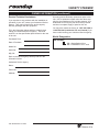
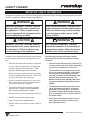
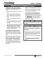
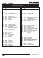
Manufacturing
Numbers:
9100210
9100212
9100218
9100220
9100222
9100224
9100230
L IS
T ED
US
Variety Steamer
I T A T IO
L IS
ERTEK
INT
N
S
C
AN
T ED
CM
C
L IS
T ED
US
Models VS-200asb & adb
P/N 1010649 Rev. G 03/12
Owner ’s Manual
Variety STeamer
Table of contents
Table of Contents........................................................2
Owner Information......................................................2
General.......................................................................2
Warranty Information..................................................2
Service/Technical Assistance.....................................3
Model Designation......................................................3
Important Safety Information.....................................4
Specifications..............................................................6
Electrical Ratings at Listed Supply Voltages..............6
Electrical Cord & Plug Configurations........................6
Capacities...................................................................6
Shipping Weight.........................................................6
Dimensions.................................................................6
Installation....................................................................7
Unpacking...................................................................7
Equipment Setup........................................................7
Operation......................................................................9
Operating Instructions................................................9
Maintenance...............................................................10
Daily Maintenance....................................................10
Monthly Maintenance...............................................11
Checking and Cleaning the Water Strainer..............11
Troubleshooting........................................................14
Replacement Parts....................................................16
Wiring Diagram..........................................................19
Limited Warranty.......................................Back Cover
Owner Information
General
Warranty Information
The Variety Steamer produces steam using plain tap
water for quick heating and reconstituting of food
items. Simple push-button action delivers an impulse
of steam. Because the amount of steam is consistent,
it removes the guesswork and produces an identically
finished product from one operator to the next.
Please read the full text of the Limited Warranty in this
manual.
If the unit arrives damaged, contact the carrier immediately and file a damage claim with them. Save all
packing materials when filing a claim. Freight damage
claims are the responsibility of the purchaser and are
NOT covered under warranty.
This manual provides the safety, installation, and operating procedures for the Variety Steamer. We recommend that all information contained in this manual be
read prior to installing and operating the unit.
The warranty does NOT extend to:
Your Variety Steamer is manufactured from the finest
materials available and is assembled to Roundup’s
strict quality standards. This unit has been tested at
the factory to ensure dependable trouble-free operation.
• Damages caused in shipment or damage as
result of improper use.
• Installation of electrical service.
• Normal maintenance as outlined in this manual.
• Malfunction resulting from improper maintenance.
• Damage caused by abuse or careless handling.
• Damage from moisture into electrical
components
• Damage from tampering with, removal of, or
changing any preset control or safety device.
Important! Keep these instructions for future reference. If the unit changes
ownership, be sure this manual accompanies the equipment.
2
A.J. Antunes & Co.
P/N 1010649 Rev. G 03/12
Variety Steamer
Owner information (continued)
Service/Technical Assistance
Use only genuine Roundup replacement parts in this
unit. Use of replacement parts other than those supplied by the manufacturer will void the warranty. Your
Authorized Service Agency has been factory trained
and has a complete supply of parts for this unit.
If you experience any problems with the installation or
operation of your unit, contact your Authorized Service
Agency. They can be found in the service agency
directory packaged with the equipment.
You may also contact the factory at 1-877-392-7854 or
1-630-784-1000 (outside the U.S and Canada) if you
have trouble locating your Authorized Service Agency.
Fill in the information below and have it handy when
calling your Authorized Service Agency. The serial
number is on the specification plate located on the rear
of the unit.
Model Designation
Purchased From:
VS-200AXX
Date of Purchase:
SB = Single Basket 20 oz.
DB = Dual Basket 10 oz. each
Model No.:
Serial No.:
Mfg. No.:
Refer to the service agency directory and fill in the
information below:
Authorized Service Agency
Name:
Phone No.:
Address:
P/N 1010649 Rev. G 03/12
3
A.J. Antunes & Co.
Variety STeamer
Important safety information
Throughout this manual, you will find the following safety words and symbols that signify important safety issues with
regards to operating or maintaining the Variety Steamer.
Warning
Warning
GENERAL WARNING. Indicates information important to the proper operation of
the equipment. Failure to observe may
result in damage to the equipment and/or
severe bodily injury or death.
ELECTRICAL WARNING. Indicates information relating to possible shock hazard.
Failure to observe may result in damage
to the equipment and/or severe bodily
injury or death.
Caution
Warning
GENERAL CAUTION. Indicates information important to the proper operation of
the equipment. Failure to observe may
result in damage to the equipment.
HOT SURFACE WARNING. Indicates
information important to the handling of
equipment and parts. Failure to observe
caution could result in personal injury.
In addition to the warnings and cautions in this manual,
use the following guidelines for safe operation of the
unit.
The following warnings and cautions appear
throughout this manual and should be carefully
observed.
• Read all instructions before using the equipment.
• For your safety, the equipment is furnished with
a properly grounded cord connector. Do NOT
attempt to defeat the grounded connector.
• Turn the unit off, disconnect the power source,
and allow unit to cool down before performing
any service or maintenance on the unit.
• The procedures in this chapter may include
the use of chemical products. These chemical products will be highlighted with bold
face letters followed by the abbreviated HCS
(Hazard Communication Standard). See
Hazard Communication Standard manual for
the appropriate Material Safety Data Sheets
(MSDS).
• The equipment should be grounded according to local electrical codes to prevent the
possibility of electrical shock. It requires a
grounded receptacle with separate electrical
lines, protected by fuses or circuit breaker of
the proper rating.
• All electrical connections must be in accordance with local electrical codes and any
other applicable codes.
• Install or locate the equipment only for its intended use as described in this manual. Do NOT use
corrosive chemicals in this equipment.
• Do NOT operate this equipment if it has a damaged cord or plug, if it is not working properly, or
if it has been damaged or dropped.
• This equipment should be serviced by qualified
personnel only. Contact the nearest Authorized
Service Agency for adjustment or repair.
• Do NOT block or cover any openings on the unit.
• Do NOT immerse cord or plug in water.
• Keep cord away from heated surfaces.
• Do NOT allow cord to hang over edge of table or
counter.
4
A.J. Antunes & Co.
P/N 1010649 Rev. G 03/12
Variety Steamer
Important safety information (continued)
• Warning electrical shock hazard.
Failure to follow these instructions
could result in serious injury or
death.
• Do NOT clean this appliance with a water jet.
-Electrical ground is required on this appliance.
• Do NOT use a sanitizing solution or abrasive
materials. The use of these may cause damage to the stainless steel finish.
• To ensure proper steaming characteristics,
some mineral deposits must be present on
generator casting. If, during cleaning, the
casting does become free of mineral deposits,
add plain tap water to casting and allow it boil
off. This will ensure proper steaming characteristics by creating a thin layer of mineral
deposits on the casting.
- Do NOT modify the power supply cord
plug. If it does not fit the outlet, have a
proper outlet installed by a qualified electrician.
- Do NOT use an extension cord with this
appliance.
Caution
All electrical connections must be in accordance
with local electrical codes and any other applicable codes.
-Check with a qualified electrician if you are
unsure whether the appliance is properly
grounded.
- The unit should be grounded according to
local electrical codes to prevent the possibility of electrical shock. It requires a
grounded receptacle with separate electrical lines, protected by fuses or circuit
breaker of the proper rating.
Warning
ELECTRICAL SHOCK HAZARD.
Failure to follow the instructions in
this manual could result in serious injury or death.
• This equipment is to be installed to comply with the basic plumbing code of the
Building Officials and Code Administrators,
Inc. (BOCA) and the Food Service Sanitation
Manual of the Food and Drug Administration
(FDA).
• Electrical ground is required on this appliance.
• Do NOT modify the power supply cord plug. If
it does not fit the outlet, have a proper outlet
installed by a qualified electrician.
• Do NOT use an extension cord with this appliance.
• Water pressure must not exceed 30 psi (2.1
kg/cm2 or 207 kPa). Higher water pressure
may cause poor performance or flooding.
To reduce water pressure, install a Water
Pressure Regulator and set between 20–25
psi (1.4–1.7 kg/cm2 or 138–172 kPa). To
order a Water Pressure Regulator from your
Authorized Service Agency, order Roundup
P/N 7000314.
P/N 1010649 Rev. G 03/12
• Check with a qualified electrician if you are
unsure whether the appliance is properly
grounded.
5
A.J. Antunes & Co.
Variety STeamer
Specifications
Electrical Ratings at Listed Supply
Voltages
Model &
Mfg. No.
Electrical Cord & Plug Configurations
Voltage
Watts
Amps
Hertz
VS-200ASB
9100210
208-240
3800
18.3-15.8
50/60
VS-200ASB
9100212
230
3490
15.2
50/60
VS-200ADB
9100218
240
3000
12.5
50/60
VS-200ADB
9100220
208-240
3800
18.3-15.8
50/60
VS-200ADB
9100222
230
3490
15.2
50/60
VS-200ADB
9100224
240
3800
15.8
50/60
VS-200ADB
9100230
208-240
3800
18.3-15.8
50/60
Model &
Mfg. No.
Description
VS-200ASB
9100212
VS-200ADB
9100222
CEE 7/7,
16 Amp., 250 VAC
(Assembly Only)
VS-200ADB
9100224
IEC-309, 16 Amp.,
250 VAC,
Pin & Sleeve
(Assembly Only)
VS-200ASB
9100210
VS-200ADB
9100220
9100230
NEMA 6-20P,
20 Amp., 250 VAC,
Non-Locking
(Assembly Only)
VS-200ADB
9100218
UK BS 1363,
13 Amp., 250 VAC
Configuration
Capacities
VS-200ADB
• 10 oz. of frozen or thawed product in each of two
baskets. Note: Pastas must be precooked.
VS-200ASB
• 20 oz. of frozen or thawed product in one basket.
Note: Pastas must be precooked.
Shipping Weight
• 42 lbs. (19 kg)
Dimensions
1
READY
2
13
3
12
4
11
STEAM
10”
(254 mm)
5
10
9
8
7
6
POWER
12”
(305 mm)
21-1/2”
(546 mm)
6
A.J. Antunes & Co.
P/N 1010649 Rev. G 03/12
Variety Steamer
Installation
Unpacking
Equipment Setup
1. Remove unit and all packing materials from shipping carton.
General
When placing the unit into service, pay attention to the
following guidelines:
2.The unit should ship with:
• Variety Steamer
• Basket Assembly (Single or Dual)
• Owner’s Manual
• Authorized Service Agency Directory
• Petro-Gel Lubricant
• Water Inlet Hose Assembly
• Black Drain Tubing
•
Make sure the power is off and the unit is at room
temperature.
•
Do NOT block or cover any openings on the unit.
•
Do NOT immerse cord or plug in water.
•
Keep cord away from heated surfaces.
NOTE: If any parts are missing or damaged, contact Antunes Technical Service IMMEDIATELY at
1-877 392-7854 or 630-784-1000 in the U.S. and
Canada.
•
Do NOT allow cord to hang over edge of table or
counter.
•
Raise the front legs so the unit is tilted slightly to
the rear (Figure 2).
3. Remove all packing materials and protective
coverings from the unit.
Electrical
1. Place the unit on a sturdy, level table or other
work surface. Turn the unit off before proceeding.
4. Remove and wash all removable parts (Baskets,
Top Housing, Drip Tray) in soap and water. Rinse with clean, hot water and allow to air dry.
2.Ensure that the line voltage corresponds to the
stated voltage on the units specification label and
power cord warning tag. Plug in the power cord.
5. Wipe all surfaces of the unit with a hot damp
cloth.
Caution
All electrical connections must be in accordance
with local electrical codes and any other applicable codes.
NOTE: Do NOT use a dripping wet cloth. Wring out
before use.
6. Reinstall all removed parts.
Top Cover Assy.
Basket Assy.
Drip Tray
RE
AD
Y
13
ST
EA
1
12
M
2
11
3
10
4
9
8
PO
WER
7
6
5
Lock Lever
Knob
Figure 1. Variety Steamer
P/N 1010649 Rev. G 03/12
7
A.J. Antunes & Co.
Variety STeamer
Installation (continued)
Warning
Be sure to follow all guidelines, procedures, and
precautions listed in the important safety information section of this manual.
5. Release the plastic tip and check the pressure on
the Water Pressure Regulator Gauge. It should
read 20 psi.
Caution
This equipment is to be installed to comply with
the basic plumbing code of the Building Officials
and Code Administrators, Inc. (BOCA) and the
Food Service Sanitation Manual of the Food and
Drug Administration (FDA).
a.) If it reads less, increase the water pressure by
pulling the black knob up and turning it clockwise.
b.) If it reads more, decrease the water pressure
by pulling the black knob up and turning it counter
clockwise.
NOTE: When adjusting the knob, you must relieve
the existing pressure by pressing the white plastic
tip on the Quick Disconnect insert for 3 seconds.
The gauge will then show the new pressure.
Plumbing
6. Once the gauge reads 20 psi, push the black
knob down to lock it in place.
NOTE: Variety Steamer models are designed to
use cold tap water.
7. Push the Quick Disconnect Insert into the fitting
at the rear of the unit until it clicks (Figure 2).
This unit requires a direct water hookup. A Water Inlet
Hose and Strainer Assembly (Figure 2) are supplied.
NOTE: Incoming water is controlled by a solenoid
valve inside the electrical housing of the steamer.
1. Turn off the Water Valve (not supplied) that provides water to the unit (Figure 2).
8. Connect the Black Drain Hose to the Drip Tray
(Figure 2). Place the other end of the hose in a
drain or collection pan.
2. Connect the 1/4” I.D. flexible tubing to the outlet
side of the Water Pressure Regulator and secure
with the Worm Clamp (Figure 2).
Caution
Water pressure must not exceed 30 psi (2.1
kg/cm2 or 207 kPa). Higher water pressure
may cause poor performance or flooding. To
reduce water pressure, install a Water Pressure
Regulator, and set the pressure between 20–25 psi
(1.4–1.7 kg/cm2 or 138–172 kPa). To order a Water
Pressure Regulator from your Authorized Service
Agency, order Roundup P/N 7000314.
NOTE: A Water Pressure Regulator (P/N 7000314)
must first be installed (Figure 2). Failure to do so
will result in poor steaming and possible flooding.
3.Turn on the Water Valve.
4. Hold the Quick Disconnect Insert over a bucket,
then press and hold the white plastic tip until
there’s a good, steady water flow. This will purge
all air out of the line.
Cold
Water
Flow
Flexible Nylon Braided
1/4 " I.D. Tubing (Not Supplied)
Shut Off Valve
(Not Supplied)
Connect Black
Drain Hose Here
Quick
Disconnect
Insert
Water Pressure Regulator
& Strainer Assy. P/N 7000314
(Not Supplied)
Connect Quick
Disconnect
Insert Here
Front Legs
Raised
Slightly
Inlet Hose &
Strainer Assy.
(Supplied)
Figure 2. Connecting Water Supply
8
A.J. Antunes & Co.
P/N 1010649 Rev. G 03/12
Variety Steamer
Operation
Operating Instructions
1. Make sure the Lock Lever is in the locked position
(Figure 4).
Operate
Button
Green
Light
2.Turn the power on and allow the unit to preheat for
approximately 20-30 minutes.
1
13
READY
12
11
10
STEAM
NOTE: The Ready Light turns on during warmup.
Yellow
Light
NOTE: Do NOT push the OPERATE button during
warmup.
4. Press and release the OPERATE button. The
Ready Light turns off and the Steam Light turns
on during steaming.
3
4
9 8 7 6
5
Lock Lever
Knob
POWER
Audio
Signal
3. Rotate the Control Knob to position 3.
2
Control
Knob
Power Switch
Figure 3. Operating Controls
Lock Lever Knob
NOTE: Allowing this first steaming cycle to finish
purges air from the water line and ensures proper
operation.
5. Place product into the Basket(s) and insert the
Basket(s) into the Top Housing.
6. Turn the Control Knob to the desired timing cycle
and press the OPERATE button.
Unlock
NOTE: Experiment by steaming product at different settings until correct cycle for that product is
found.
Locked Position
Figure 4. Lock Lever
Warning
To avoid injury, be careful when pulling basket
assembly out from unit. Be sure to allow steam
to escape before putting hands or face over the
steamer.
7. When the audio alarm sounds, remove and
empty the basket(s).
8.At the end of the serving day or shift, turn the unit
off and allow it to cool down before performing
the procedures under “Daily Maintenance” in the
Maintenance section of this manual.
P/N 1010649 Rev. G 03/12
9
A.J. Antunes & Co.
Variety STeamer
Maintenance
Daily Maintenance
Warning
Turn the power off, unplug the power cord, and
allow the unit to cool down before performing any
service or maintenance on the unit.
NOTE: Frequency of cleaning is determined by
water conditions, usage and water filter systems.
1.Turn the power off, unplug the power cord, and
allow the unit to cool down.
CAUTION
Chlories or phosphates in cleaning agents such
as bleach, sanitizers, degreasers, or detergents
could cause permanent damage to the stainless
steel equipment. The damage is ususally in the
form of discoloration, dulling of metal surface finish, pits, voids, holes, or cracks. This damage is
permanent and not covered by warranty. The following tips are recommended for maintenance of
your stainless steel equipment:
•
•
3. Remove the Basket(s), Top Cover Housing
Assembly, and Drip Tray. Wash them in hot soapy
water, rinse, and allow to air dry.
4. Move the Locking Lever to the unlocked position.
Remove the Black Manifold Plate, the large black
O-Ring from the plate, and the Diffuser Plate. Always use a soft, damp cloth for cleaning,
rinse with clear water, and wipe dry. When
required, always rub in the direction of the
metal polish lines.
5. Remove the Spray Tube by carefully lifting the
loose end and gently twisting and pulling it out of
the steam generator hole.
Routine cleaning should be done daily using
soap, ammonia detergent, and water.
•
Stains and spots should be removed using a
vinegar solution.
•
Finger marks and smears should be removed
using soap and water.
•
2.Check the rear water quick disconnect fitting and
all hose clamp connections for leaks. Tighten all
clamps or replace part(s) if necessary.
6. Use a suitable 1/16” punching tool (such as a
large paperclip) to clean all 12 holes in the Black
Manifold as well as the six holes in the Spray
Tube. Then wash all items in hot soapy water,
rinse, and allow them to air dry.
7. Reinstall the Spray Tube into the Steam
Generator hole and reinstall the Diffuser Plate.
Hard water spots should be removed using a
vinegar solution.
8. Lightly apply some Petro-Gel (supplied) onto the
large black O-ring and reinstall the O-ring onto
the Manifold Plate.
Caution
Do NOT use a sanitizing solution or abrasive
materials. The use of these may cause damage to
the stainless steel finish.
9. Hold the Manifold Plate up to a light and verify
that light is visible through all of the holes. If not,
use the punching tool to clean any clogged holes.
Caution
If a chemical cleaner is used, be sure it is safe to
use on cast aluminum. Observe all precautions
and warnings on product label.
10.Seat the Manifold Plate on the Generator and pull
the Locking Lever forward to lock the plate.
11.Check that the Water Pressure Regulator is
correctly set at 20–25 psi (1.4–1.7 kg/cm2 or
138–172 kPa.)
Caution
Failure to regularly and/or properly clean this
equipment may damage it or cause the user
bodily injury.
12. Re-install all parts and accessories. Plug power
cord into electrical outlet.
10
A.J. Antunes & Co.
P/N 1010649 Rev. G 03/12
Variety Steamer
Maintenance (continued)
Monthly Cleaning
7. Using a sponge or a dry towel, remove the
delimer solution from the Generator surface, then
rinse with clean water.
Your steamer utilizes an open steam generator. Water
sprayed onto the Generator surface flashes into
steam immediately, but the minerals in the water do
not steam; they stay on the Generator surface and
accumulate. A small amount of calcium/mineral
deposits are needed for proper operation, but a
build-up of excessive calcium/mineral deposits causes
poor steaming efficiency and excessive moisture (wet
steam), which will eventually hinder the steaming
action completely.
NOTE: To ensure proper steaming characteristics,
some calcium/mineral deposits must be present
on the Generator surface. If during cleaning, the
surface becomes free of calcium/mineral deposits,
add plain tap water to the surface and allow it to
boil off. If necessary, repeat this several times in
order to formulate a thin coating of calcium/mineral
deposits.
1.Turn the power off, unplug the power cord, and
allow the unit to cool down.
NOTE: In soft water areas, it may be necessary to
“season” the Generator surface with a small amount
of calcium deposits. This ensures proper steaming
characteristics by creating a thin coating of calcium/
mineral deposits. Seasoning mixture consists of
3/4 ounce (25ml/25cc) of baking soda, 3/4 ounce (25
ml/25cc) of lime, and 1 quart (950ml/950cc) of water.
Stir mixture and pour 1/4” deep onto hot Generator
surface. After mixture is converted to steam, the
remaining loose powder can be removed.
2. Perform the steps under Daily Cleaning, but do
NOT reassemble the unit.
3. Use a scraper or non-abrasive brush to loosen
and remove excessive calcium/mineral deposits
from the Generator surface.
4. Remove the loose build-up by wiping the
Generator with a clean, damp cloth.
8. Plug the power cord in, turn the power on, and
allow the unit to warm up for 30 minutes.
5. Reassemble the unit.
10. Set the Control Knob to “3” and push the
OPERATE button to run a 30-second cycle of
steam. This purges any remaining delimer residue from the Generator surface.
NOTE: If the deposits are still excessive and/or
difficult to remove, see Steps 6 through 8.
6. Pour delimer solution (not supplied) onto the
Generator surface. Be sure to follow the delimer
manufacturer’s instructions for proper mixture and
use.
11.Turn the power off and reassemble the unit.
CAUTION
If a chemical cleaner/delimer is used, be sure it is
safe to use on cast aluminum. Observe all precautions and warnings on the product label.
P/N 1010649 Rev. G 03/12
11
A.J. Antunes & Co.
Variety STeamer
Maintenance (continued)
Checking and Cleaning the Water Strainer
The Water Strainer protects your equipment by
preventing foreign debris from reaching the water line,
which could get into the food, damage the unit’s solenoid (causing the unit to leak or flood), or interfere with
the equipment’s proper and consistent operation.
To ensure proper and consistent steaming results,
inspect the Water Pressure Regulator and strainer cup
regularly. If the pressure is lower than 20 psi (1.4 kg/
cm2 or 138 kPa), check the clear, plastic strainer cup
and clean out the accumulated debris as follows:
1.Shut off the water supply valve to the unit,
unscrew the clear plastic strainer cup, and carefully remove the mesh strainer screen.
2.At the sink, gently flush all of the built-up debris
from the strainer cup and mesh strainer. Be careful not to damage the mesh strainer screen.
3 Place the mesh strainer screen into its seat at the
bottom of the clear, plastic cup and ensure the
orange O-ring is properly seated in place before
screwing the strainer cup and top back together.
4. Purge the air out of the strainer and tubing by disconnecting the male quick disconnect insert from
the equipment and, over a bucket, push the white
plastic tip in until there is steady water flow.
5. Replace damaged or worn parts as needed.
6. Verify that the Water Pressure Regulator is set to
20–25 psi (1.4–1.7 kg/cm2 or 138–175 kPa).
12
A.J. Antunes & Co.
P/N 1010649 Rev. G 03/12
Variety Steamer
Maintenance (continued)
Black Manifold Plate (2)
Black Manifold Orifices
O-ring (3)
Top Cover Assy. (1)
Drip Tray (4)
Diffuser (38)
Spray Tube (37)
Hi-Limit
Thermostat (35)
Control Panel
Screws (59)
Steam Generator
Control Panel (32)
Control Panel
Screws (59)
NOTE: Numbers in parenthesis
correspond with Replacement Parts list.
Figure 5. Variety Steamer Components
P/N 1010649 Rev. G 03/12
13
A.J. Antunes & Co.
Variety STeamer
Troubleshooting
Warning
To avoid possible personal injury and/or damage to the unit, qualified service personnel should inspect, test,
and repair all electrical equipment. The unit should be unplugged when servicing, except when electrical tests
are required. Use extreme care during electrical circuit tests. Live circuits will be exposed.
Problem
The unit is on, but the
Switch Indicator Light is
still off and the unit is not
heating up.
Possible Cause
Corrective Action
The power cord is not correctly plugged
in.
Plug the power cord in correctly.
The power cord and/or electrical plug is
damaged.
Inspect electrical wire, plug, and receptacle.
The main electrical panel circuit breaker
is off or has been tripped.
Reset circuit breaker. Contact your maintenance person or Authorized Service
Agency if it trips again.
Switch is inoperable.
Contact your maintenance person or
Authorized Service Agency for service.
The unit’s main electrical
panel circuit breaker trips.
Damaged receptacle, plug, or cord; a
loose connection or an internal component failure.
Turn the unit off, allow it to cool to room
temperature, and then restart the unit.
Contact your maintenance person or
Authorized Service Agency if condition
repeats.
The unit is on, the switch
indicator light is on, but
the unit is not heating up.
Hi-Limit Thermostat is tripped.
Loose/burnt wiring.
Reset the Hi-Limit according to the
Operation section of this manual. If it
requires continuous resetting or repair,
contact your maintenance person or
Authorized Service Agency for service.
Water Line Valve is closed.
Check that the Water Line Valve is open.
Filter Strainer is restricted.
Check and clean the Filter Strainer as
described in the Maintenance section of
this manual.
Unit heats but there is little or no steam produced
Inoperable Thermostat.
Inoperable Generator.
and/or
The product requires more Quick Disconnect is not fully engaged at
steaming than usual.
rear of unit or is damaged.
Low or no water pressure in water line.
Remove the Quick Disconnect Insert from
the rear of the unit. While holding over a
bucket, press the white plastic tip. Strong
water flow should be noted. If so, reconnect firmly into unit.
Spray Tube orifices are restricted.
Remove and clean the Spray Tube according to the Daily Maintenance procedures
found in this manual.
Black Manifold orifices are restricted.
Remove and clean the Black Manifold
according to the Daily Maintenance procedures found in this manual.
Unit is not being cleaned daily and/or
properly.
Clean unit daily according to the Daily
Maintenance procedures found in this
manual.
Improper water pressure to unit.
Verify that a Water Pressure Regulator is
installed and set to 20–25 psi.
14
A.J. Antunes & Co.
Remove and re-engage the Quick
Disconnect Insert firmly until a “click” is
heard. Replace if damaged.
P/N 1010649 Rev. G 03/12
Variety Steamer
Troubleshooting (continued)
Problem
Possible Cause
Unit heats but there is little Insufficient or excessive calcium/mineral
or no steam produced
buildup on Generator Surface.
and/or
Corrective Action
Verify that a thin layer of calcium/mineral deposits is present on the Generator
Surface. Refer to the Maintenance section
of this manual.
The product requires more Black Manifold O-ring is worn, damaged,
or missing.
steaming than usual.
Low Generator temperature.
(Continued)
Replace the Black Manifold O-ring if worn,
damaged, or missing.
Steam leaks out of the
sides of the unit.
Black Manifold O-ring is damaged or
missing.
Replace the Black Manifold O-ring if worn,
damaged, or missing.
Black Manifold is difficult
to remove or reinstall onto
the Generator.
Black Manifold not being removed and
cleaned daily as required.
Remove and clean the Black Manifold daily
according to the Maintenance section of
this manual.
Black Manifold O-ring is damaged or
worn.
Replace the Black Manifold O-ring if damaged or worn.
Black Manifold O-ring is not being
lubricated daily with Petro-Gel.
Lubricate the Black Manifold O-ring daily
according to the Maintenance section of
this manual.
Solenoid valve is being held open by
debris from the building’s water line
piping.
NOTE: Verify that there is a pre-strainer/
filter on the water line just before the unit.
Attempt to flush the debris out of the valve
by running the unit on a number of cycles
and then letting it rest. If the unit still
leaks, contact your maintenance person or
Authorized Service Agency.
Unit floods overnight
and/or continues to steam
even when just in ready
mode.
P/N 1010649 Rev. G 03/12
Verify Generator Surface temperature is at
least 380°F (193°C),
15
A.J. Antunes & Co.
Variety STeamer
Replacement Parts
Water Pressure Regulator Kit - Part No. 7000314
1
4
3
6
Item
1
2
2
3
4
5
6
7
5
Part
No.
0503849
2040130
See Below
2170113
7000306
2190129
211P104
Description
Bracket
Qty.
Male Adapter, Barbed 1/4”
For Strainer Parts Identification
Regulator, Pressure
Gauge, Water Pressure
Nipple, 1/4” NPT x 1/4” NPT
Clamp, Worm (not shown)
1
2
1
1
1
2
1/4
Item
NPT
2
NOTE: Item 1
is made up
of Items 2–4.
1
2
3
4
2
7000333
2040130
7000334
2110104
Description
Qty.
Water Line Strainer Kit
1
Male Adapter, Barbed 1/4”
2
Replacement Screen and O-ring Kit 1
Clamp, Worm (not shown)
2
3
16
A.J. Antunes & Co.
Part
No.
P/N 1010649 Rev. G 03/12
Variety Steamer
Replacement parts (continued)
43
2
17
67
3
18
38
44
37
39
63
40
5
4
40
1
42
63
74
36
6
12
68
9
69
70
34
8
13
11
71
66
60
64
C
65
51
35
59
73
72
8
10
21
16
15
19
53
14
7
55
58
54
22
33
49
32
57
58
20
31
56
23
30
29
28
27
P/N 1010649 Rev. G 03/12
57
24
25
26
17
A.J. Antunes & Co.
Variety STeamer
Replacement parts (continued)
Item
1
2
3
4
5
Part
No.
0021042
0100180
0200121
0010336
7000388
0100259
6
2020104
7
040K103
8
0501139
9
001K125
10 2100138
11 0021044
12 7000449
13 200K126
14 0020419
15 200K127
16 208K106
17 7000139
18 0010584
19 0700452
0700453
0700437
0700556
20 210K230
21 0020443
22 4050170
23 4020131
24 1000955
25 210K122
26 210K108
27 7000542
28 2100123
29 4010166
30 4060208
31 4060179
32 0021043
33 402K169
Description
Qty.
Item
Top Housing Assy.
1
Generator Manifold
1
O-ring
1
Drip Tray Assy.
1
Generator, 3800W (240V)
1
Generator, 3000W (240V)
(Mfg. No. 9100218 only)
Drain Tube
1
Insulation Kit
1
Retainer, Generator
2
Lock Lever and Support Assy. 1
Ball Knob
1
Lever Support
1
Tube 4 1/2”
1
Generator Tube Kit
1
Solenoid Valve with Fittings
1
Inlet Tube Kit
1
Quick Disconnect Body
1
Quick Disconnect Insert
1
Inlet Hose Assy. with Strainer
1
Power Cord 6-20P
1
(Mfg. No. 9100210, 220, & 230)
Power Cord CEE 7/7
1
(Mfg. No. 9100212 & 222)
Power Cord IEC-309
1
(Mfg. No. 9100224)
Power Cord UK BS 1363 250 V, 13 A 1
(Mfg. No. 9100218)
Leg Kit (Qty. 4)
1
Base
1
Pot. and Low Voltage
Wiring Harness
1
Audio Signal
1
Label, Control Panel
1
Adjustable Leg Kit (Qty. 4)
(Incl. No. 26)
1
Rubber Tip Kit (Qty. 4)
1
Power Switch
1
Adjusting Knob
1
Switch, Operate
1
LED Light, Yellow (Steam)
1
LED Light, Green (Ready)
1
Control Panel
1
Solid State Control
1
Description
Qty.
34 403K157
Thermostat
35 7000344
Hi-limit Thermostat
36 0021046
Main Housing
37 0020269
Spray Tube
38 0500625
Diffuser
39 2100119
Large Basket Handle
40 2100240
Handle Guard, Black
42 2100107
Small Basket Handle 43 0010550
Large Basket Assy. 20 oz.
44 0010551
Small Basket Assy. 10 oz.
45 0010570
Rice Basket Assy. 10 oz. (not shown)
(Mfg. No. 9100230 only)
46 001K717
Egg Poach Basket Kit (not shown)
47 0700523
Wire Set (not shown)
48 2140116
Petrol-Gel (not shown)
49 7000136
Terminal Block
50 306P104* Screw, Truss Hd., #6-32 x 1/4” SS
51 325P109* Bolt, Hex Hd., 1/4-20 x 1/2”
52 325P134* Setscrew, 1/4-20 x 3/4”
53 308P115* Screw, Pan Hd., #8-32 x 3/8” SS
54 040P112* Strain Relief
55 308P143* Nut, Hex, KEPS, #8-32
56 310P109* Screw, Pan Hd., #10-32 x 3/8” SS
57 306P113* Screw, Round Hd., #6-32 x 5/8”
58 306P116* Nut, Hex, #6-32
59 308P103* Screw, Truss Hd., #8-32 x 1/4” SS
60 308P128* Screw, Binder Hd., Brass,
#8-32 x 1/4”
61 020P117* O-ring, 5/16” I.D.
62 308P110* Screw, Binder Hd., Nickel,
#8-32 x 5/16”
63 338P102* Bolt, Carriage, 3/8-16 x 3/4” SS
64 040P111
Snap Bushing
65 325P104* Flat Washer 1/4”
66 0503989
Bracket, Hi-Limit
67 See page 16 for Strainer Parts identification
68 325P169* Bolt, Shoulder 5/16” x 1/2”
69 212P120* Spacer, St. Stl.
70 212P118* Flat, Washer St. Stl.
71 325P154* Wash, 1/4” Spring Lock
72 325P102* Nut, Hex 1/4” - 20
73 0021051
Lock Lever Weldment
* Only available in packages of 10.
18
A.J. Antunes & Co.
Part
No.
1
1
1
1
1
1
1
1
1
2
2
2
1
1
1
1
1
1
1
1
1
1
1
1
1
1
1
1
1
1
1
1
1
1
1
1
1
1
P/N 1010649 Rev. G 03/12
Variety Steamer
Wiring Diagram
P/N 1010649 Rev. G 03/12
19
A.J. Antunes & Co.
Limited Warranty
Equipment manufactured by Roundup Food Equipment Division of A.J. Antunes & Co. has been constructed of the finest materials available and manufactured to high quality standards. These units are
warranted to be free from electrical and mechanical defects for a period of one (1) year from date of
purchase under normal use and service, and when installed in accordance with manufacturer’s recommendations. To insure continued operation of the units, follow the maintenance procedures outlined in
the Owner’s Manual. During the first 12 months, electro-mechanical parts, non-overtime labor, and travel expenses up to 2 hours (100 miles/160 km), round trip from the nearest Authorized Service Center
are covered.
1.This warranty does not cover cost of installation, defects caused by improper storage or handling prior to
placing of the Equipment. This warranty does not cover overtime charges or work done by unauthorized
service agencies or personnel. This warranty does not cover normal maintenance, calibration, or regular
adjustments as specified in operating and maintenance instructions of this manual, and/or labor involved
in moving adjacent objects to gain access to the equipment. This warranty does not cover consumable/
wear items. This warranty does not cover damage to the Load Cell or Load Cell Assembly due to abuse,
misuse, dropping of unit/shock loads or exceeding maximum weight capacity (4 lbs). This warranty does
not cover water contamination problems such as foreign material in water lines or inside solenoid valves.
It does not cover water pressure problems or failures resulting from improper/incorrect voltage supply.
This warranty does not cover Travel Time & Mileage in excess of 2 hours (100 miles/160 km) round trip
from the nearest authorized service agency.
2.Roundup reserves the right to make changes in design or add any improvements on any product. The
right is always reserved to modify equipment because of factors beyond our control and government
regulations. Changes to update equipment do not constitute a warranty charge.
3.If shipment is damaged in transit, the purchaser should make a claim directly upon the carrier. Careful inspection should be made of the shipment as soon as it arrives and visible damage should be noted upon the carrier’s receipt. Damage should be reported to the carrier. This damage is not covered under this warranty.
4.Warranty charges do not include freight or foreign, excise, municipal or other sales or use taxes. All such
freight and taxes are the responsibility of the purchaser.
5.this warranty is exclusive and is in lieu of all other warranties, expressed or implied, including any implied warranty or merchantability or fitness for a particular purpose, each of which is hereby expressly disclaimed. the remedies described above are exclusive and in no event shall roundup be liable for special consequential or incidental damages for the breach or delay in performance of this warranty.